JP6774356B2 - Surveillance camera - Google Patents
Surveillance cameraDownload PDFInfo
- Publication number
- JP6774356B2 JP6774356B2JP2017038647AJP2017038647AJP6774356B2JP 6774356 B2JP6774356 B2JP 6774356B2JP 2017038647 AJP2017038647 AJP 2017038647AJP 2017038647 AJP2017038647 AJP 2017038647AJP 6774356 B2JP6774356 B2JP 6774356B2
- Authority
- JP
- Japan
- Prior art keywords
- tilt
- housing
- pan
- surveillance camera
- axis
- Prior art date
- Legal status (The legal status is an assumption and is not a legal conclusion. Google has not performed a legal analysis and makes no representation as to the accuracy of the status listed.)
- Active
Links
Images


Landscapes
- Closed-Circuit Television Systems (AREA)
- Studio Devices (AREA)
- Camera Bodies And Camera Details Or Accessories (AREA)
- Accessories Of Cameras (AREA)
Description
Translated fromJapanese本開示は、監視対象のエリアを撮像する監視カメラに関する。 The present disclosure relates to a surveillance camera that captures an area to be monitored.
従来、旋回、チルト、ズームの動作(PTZ(Pan Tilt Zoom)の各種動作)が可能なPTZカメラが監視カメラの一例として使用されている。PTZ型の監視カメラは、パン旋回がエンドレス回転となることにより、全方位の撮像情報を遠隔操作で得ることが可能である。撮像情報の収集性能に優れたPTZ型の監視カメラは、防犯、防災等の広範囲での用途があり、特に日射風雨降雪等に対する耐候性能を高めたい要請がある。 Conventionally, a PTZ camera capable of turning, tilting, and zooming (various PTZ (Pan Tilt Zoom) operations) has been used as an example of a surveillance camera. The PTZ type surveillance camera can obtain omnidirectional imaging information by remote control because the pan rotation is endless rotation. PTZ type surveillance cameras with excellent imaging information collection performance have a wide range of applications such as crime prevention and disaster prevention, and there is a demand to improve the weather resistance performance against sunlight, wind, rain and snow.
一般的に、監視カメラの耐候性を高めたい場合には、監視カメラの撮像部分を含む筐体本体をドームカバーで覆うことが多い。ところが、ドームカバーは、半球面のカバーであることから設置面側の撮像が行えない。そこで、パン回転部、チルト回転部に防水構造を有することで、ドームカバーを使用せずに、設置面側の撮像を可能にしつつ、耐候性を高めたPTZ型の監視カメラの例が提案されている(例えば特許文献1等参照)。 Generally, when it is desired to improve the weather resistance of a surveillance camera, the housing body including the imaging portion of the surveillance camera is often covered with a dome cover. However, since the dome cover is a hemispherical cover, it is not possible to take an image on the installation surface side. Therefore, an example of a PTZ type surveillance camera with improved weather resistance has been proposed while enabling imaging on the installation surface side without using a dome cover by having a waterproof structure for the pan rotating part and the tilt rotating part. (See, for example, Patent Document 1 and the like).
しかし、例えば監視カメラを寒冷地で使用する際、特許文献1の構成を用いてもカメラレンズの前方に氷柱(つらら)が付着する場合がある。カメラレンズの前方に付着した氷柱は、撮像画像の一部分として映ることがあり、所望の被写体の撮像画像の視認性を劣化させる。一方、監視カメラにヒータ又は氷柱溶解用噴射装置等の氷柱除去装置を装備すれば、イニシャルコスト及びランニングコストの双方が増大する。そのため、大掛かりな装置を付設することなく、氷柱を除去したい要請があるが、依然として特許文献1の構成ではその要請を満たすことは困難である。 However, for example, when a surveillance camera is used in a cold region, icicles may adhere to the front of the camera lens even if the configuration of Patent Document 1 is used. The icicles attached to the front of the camera lens may appear as a part of the captured image, which deteriorates the visibility of the captured image of the desired subject. On the other hand, if the surveillance camera is equipped with an icicle removing device such as a heater or an icicle melting injection device, both the initial cost and the running cost increase. Therefore, there is a request to remove the icicle without attaching a large-scale device, but it is still difficult to satisfy the request with the configuration of Patent Document 1.
本発明は、上記状況に鑑みて案出され、付属部品の増加を抑制しつつ、撮像用のレンズの前面に付着する氷柱を除去できる監視カメラを提供することを目的とする。 The present invention has been devised in view of the above circumstances, and an object of the present invention is to provide a surveillance camera capable of removing icicles adhering to the front surface of an imaging lens while suppressing an increase in accessories.
本開示は、パン軸を中心に旋回駆動されるパンハウジングと、前記パンハウジングの側部に、基端が支持される支持アームと、前記支持アームの先端に、前記パン軸に直交するチルト軸により回転駆動自在に支持され、前記チルト軸に直交する方向が光軸となるレンズを有するチルトハウジングと、前記チルトハウジングに、前記光軸に沿う方向で延出して設けられ、前記レンズへの外乱光の入射を抑制する庇部と、前記チルト軸の少なくとも一方を中心とした前記チルトハウジングのチルト回転駆動に基づく前記庇部の接近に応じて、前記庇部に付着した障害物を除去する前記パンハウジングの前側外表面部と、を備える、監視カメラを提供する。 In the present disclosure, a pan housing that is swiveled around a pan axis, a support arm whose base end is supported on a side portion of the pan housing, and a tilt axis orthogonal to the pan axis at the tip of the support arm. A tilt housing having a lens that is rotatably supported by the tilt housing and whose optical axis is perpendicular to the tilt axis, and a tilt housing that extends in a direction along the optical axis and disturbs the lens. The obstruction attached to the eaves is removed in response to the approach of the eaves that suppress the incident of light and the eaves based on the tilt rotation drive of the tilt housing centered on at least one of the tilt axes. Provided is a surveillance camera comprising a front outer surface portion of a pan housing.
また、本開示は、パン軸を中心に旋回駆動されるパンハウジングと、前記パンハウジングの側部に、前記パン軸に直交する第1チルト軸により基端が回転駆動自在に支持される支持アームと、前記支持アームの先端に、前記第1チルト軸と同方向の第2チルト軸により回転駆動自在に支持され、前記第2チルト軸に直交する方向が光軸となるレンズを有するチルトハウジングと、前記チルトハウジングに、前記光軸に沿う方向で延出して設けられ、前記レンズへの外乱光の入射を抑制する庇部と、前記第1チルト軸及び前記第2チルト軸の少なくとも一方を中心とした前記チルトハウジングのチルト回転駆動に基づく前記庇部の接近に応じて、前記庇部に付着した障害物を除去する前記パンハウジングの前側外表面部と、を備える、監視カメラを提供する。 Further, the present disclosure discloses a pan housing that is swiveled around a pan shaft, and a support arm whose base end is rotatably supported by a first tilt shaft orthogonal to the pan shaft on a side portion of the pan housing. A tilt housing having a lens at the tip of the support arm, which is rotationally driven by a second tilt axis in the same direction as the first tilt axis and whose optical axis is in a direction orthogonal to the second tilt axis. The tilt housing is provided so as to extend in a direction along the optical axis, and is centered on an eaves portion that suppresses the incident of ambient light on the lens, and at least one of the first tilt axis and the second tilt axis. Provided is a surveillance camera including a front outer surface portion of the pan housing for removing obstacles adhering to the eaves in response to the approach of the eaves based on the tilt rotation drive of the tilt housing.
また、本開示は、レンズを有するチルトハウジングと、前記レンズを覆うカバーガラスと、前記カバーガラスを挟んで前記レンズと反対側に前記チルトハウジングから前記レンズの光軸に沿う方向で延出し、前記レンズへの外乱光の入射を抑制する庇部と、ワイパアームの移動に応じて、前記カバーガラスの外表面を拭くワイパと、前記ワイパアームから前記光軸に沿う方向で前記カバーガラスと反対側に突出し、前記ワイパアームの移動に応じて、前記庇部に付着した障害物を除去する障害物除去部材と、を備える、監視カメラを提供する。 Further, in the present disclosure, a tilt housing having a lens, a cover glass covering the lens, and a cover glass extending from the tilt housing to the opposite side of the lens in a direction along the optical axis of the lens are described. An eaves that suppresses the intrusion of ambient light onto the lens, a wiper that wipes the outer surface of the cover glass in response to the movement of the wiper arm, and a wiper that protrudes from the wiper arm toward the opposite side of the cover glass in the direction along the optical axis. Provided is a surveillance camera including an obstacle removing member for removing an obstacle adhering to the eaves in response to the movement of the wiper arm.
本発明によれば、付属部品の増加を抑制しつつ、撮像用のレンズの前面に付着する氷柱を除去できる。 According to the present invention, it is possible to remove icicles adhering to the front surface of an imaging lens while suppressing an increase in accessories.
以下、適宜図面を参照しながら、本開示に係る監視カメラの詳細を具体的に開示した各実施の形態を詳細に説明する。但し、必要以上に詳細な説明は省略する場合がある。例えば、既によく知られた事項の詳細説明や実質的に同一の構成に対する重複説明を省略する場合がある。これは、以下の説明が不必要に冗長になることを避け、当業者の理解を容易にするためである。なお、添付図面及び以下の説明は、当業者が本開示を十分に理解するために提供されるものであり、これらにより特許請求の範囲に記載の主題を限定することは意図されていない。 Hereinafter, each embodiment in which the details of the surveillance camera according to the present disclosure are specifically disclosed will be described in detail with reference to the drawings as appropriate. However, more detailed explanation than necessary may be omitted. For example, detailed explanations of already well-known matters and duplicate explanations for substantially the same configuration may be omitted. This is to avoid unnecessary redundancy of the following description and to facilitate the understanding of those skilled in the art. It should be noted that the accompanying drawings and the following description are provided for those skilled in the art to fully understand the present disclosure, and are not intended to limit the subject matter described in the claims.
以下の実施の形態では、2つのチルト軸を有する監視カメラを例示して説明するが、これに限定されない。なお、以下の実施の形態では、チルト軸には、物理的なチルト軸の他、仮想的な軸(チルト回転中心)が含まれてもよい。同様に、パン軸には、物理的なパン軸の他、仮想的な軸(パン回転中心)が含まれてもよい。 In the following embodiments, a surveillance camera having two tilt axes will be described as an example, but the present invention is not limited thereto. In the following embodiments, the tilt axis may include a virtual axis (tilt rotation center) in addition to the physical tilt axis. Similarly, the pan axis may include a virtual axis (pan rotation center) in addition to the physical pan axis.
(実施の形態1)
先ず、実施の形態1に係る監視カメラの例について説明する。(Embodiment 1)
First, an example of the surveillance camera according to the first embodiment will be described.
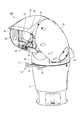
図1は、実施の形態1に係る監視カメラの斜視図である。なお、本実施の形態において、上下前後左右の方向は、図1に示した矢印の方向に従うものとする。 FIG. 1 is a perspective view of the surveillance camera according to the first embodiment. In this embodiment, the directions of up, down, front, back, left and right follow the direction of the arrow shown in FIG.
実施の形態1に係る監視カメラ100は、本体ハウジング11と、パンハウジング13と、チルトハウジング15と、を有する。本体ハウジング11は、取付台であり、下面(図1の下側の面)が取付面となる。本体ハウジング11は、例えば、取付面側がその反対側よりも若干大径となった略円柱形状に形成される。監視カメラ100は、本体ハウジング11の取付面がボルト17等の締結具によって、被固定面に固定される。 The
図2は、図1に示した監視カメラの正面図である。 FIG. 2 is a front view of the surveillance camera shown in FIG.
パンハウジング13の側部には、支持アーム19が取り付けられる。パンハウジング13は、本体ハウジング11の上面に、パン軸Pcを中心に、パン回転自在に支持され、旋回駆動される。パン軸Pcは、本体ハウジング11の軸線と一致する。 A
パンハウジング13には、パン駆動装置21が設けられる。パン駆動装置21は、パン軸Pcと、パンモータ23と、シャフト25と、中間ウォームホイール27と、中間ウォーム29と、を有する。 The
パンモータ23は、パンハウジング13に固定され、上側へ突出させた駆動軸を有する。パンモータ23の駆動軸には、駆動ウォーム31が固定される。パンハウジング13には、パンモータ23とパン軸Pcとの間に、パン軸Pcに直角に交差する方向のシャフト25が回転自在に支持される。シャフト25の一端には、駆動ウォーム31に噛合する中間ウォームホイール27が固定される。シャフト25の他端には、パンウォームホイール33に噛合する中間ウォーム29が固定される。 The
従って、パンモータ23が駆動され、駆動ウォーム31がシャフト25の中間ウォームホイール27に回転を伝達すると、シャフト25が回転する。シャフト25が回転することで、中間ウォーム29が、本体ハウジング11に固定されているパンウォームホイール33の外周を回る。つまり、中間ウォーム29は、パン軸Pcの回りを公転する。これにより、パンハウジング13は、パン軸Pcを中心にパン回転駆動される。 Therefore, when the
パンハウジング13は、側部に1本の支持アーム19の基端を支持する。即ち、支持アーム19は、パンハウジング13と一体にパン回転する。パンハウジング13は、支持アーム19の基端を、パン軸Pcから離れて直角に交差する第1チルト軸T1cによって回転自在に支持する。つまり、支持アーム19は、第1チルト軸T1cを中心に傾動可能となる。支持アーム19は、パンハウジング13から起立して、先端でチルトハウジング15を支持する。 The
側部に支持アーム19を支持したパンハウジング13は、前側に、前側外表面部35(図1参照)を有する。 The
チルトハウジング15には、チルト駆動装置37が設けられる。チルト駆動装置37は、第1チルト軸T1cと、支持アーム19と、第1チルトモータ39と、第1チルトモータ39と、第2チルト軸T2cと、を有する。 The
チルトハウジング15は、例えば、楕円の長軸を中心に回転させた略楕円回転体形状に形成される。チルトハウジング15は、略楕円回転体形状の一部分が切除されている。この一部分には、支持アーム19の先端が配置される。チルトハウジング15は、この支持アーム19の先端に、直径方向の一端が、第1チルト軸T1cと平行な第2チルト軸T2cを中心にチルト回転自在に支持される。つまり、チルトハウジング15は、第2チルト軸T2cにより回転駆動自在に支持される。 The
第2チルト軸T2cは、例えば、略楕円回転体形状に形成されたチルトハウジング15の中心を通る。チルトハウジング15は、パンハウジング13から上方に離間して支持アーム19に支持される。つまり、チルトハウジング15は、支持アーム上下端の第1チルト軸T1cと第2チルト軸T2cとの2つの軸によってチルト回転が可能となっている。これにより、チルトハウジング15は、パンハウジング13からせり出し(パン軸Pcから離反する方向に移動)可能となっている。 The second tilt axis T2c passes through the center of the
なお、本実施の形態に係る監視カメラ100は、支持アーム19の基端が、パンハウジングの側部に固定されてもよい。この場合、第1チルト軸T1cは、省略される。第1チルト軸T1cが省略された監視カメラでは、チルトハウジング15が、第2チルト軸T2cを中心にチルト回転駆動される。第2チルト軸T2cのみによりチルト回転駆動する監視カメラによれば、後述するように、前側外表面部35とチルト回転駆動とを利用して、付属部品を追加せずに氷柱69を最も経済的にかつ効率よく除去することができる上、部品点数を削減し、構造を簡素とし、装置を軽量化できる。 In the
支持アーム19は、ウォームホイール41と、第1チルトモータ39とを有する。ウォームホイール41は、第1チルト軸T1cと同軸となって、パンハウジング13に固定される。第1チルトモータ39は、支持アーム19に固定される。第1チルトモータ39は、駆動軸に固定されたウォーム43が、ウォームホイール41に噛み合う。第1チルトモータ39は、駆動軸の回転によって、パンハウジング13に対して、第1チルト軸T1cを中心に支持アーム19を回転させる。 The
また、支持アーム19の先端には、チルトハウジング15を回転させる第2チルトモータ45が設けられる。第2チルトモータ45は、駆動軸の回転によって、支持アーム19に対して、第2チルト軸T2cを中心にチルトハウジング15を回転させる。これにより、チルトハウジング15は、第1チルト軸T1c及び第2チルト軸T2cの何れか一方またはその双方を中心にチルト回転駆動される。 A
監視カメラ100には、コントローラ47が設けられる。コントローラ47は、第2チルトモータ45と、第1チルトモータ39と、を同期回転させることができる。この同期回転は、同じ角速度で、又は異なる角速度で、第1チルトモータ39と第2チルトモータ45とを同方向に回転できる。また、同期回転は、同じ角速度で、又は異なる角速度で、第1チルトモータ39と第2チルトモータ45とを逆方向にも回転できる。 The
監視カメラ100は、チルトハウジング15にカメラ49を収容する。監視カメラ100は、パン軸Pcが鉛直方向に沿い、パン軸Pc上にチルトハウジング15の中心が位置する図1、図2に示した姿勢が正置姿勢となる。このとき、カメラ49の光軸Ocは、パン軸Pcに直交する。このときの光軸Ocの方向は前方となる。 The
監視カメラ100では、支持アーム19の基端の第1チルト軸T1cが、パン軸Pcから前方に所定のオフセット距離だけ離れている。これにより、チルトハウジング15は、その離れた方向に傾動することで、パンハウジング13からの前方へのせり出し量を大きく確保できる。その結果、監視カメラ100は、特に真下を監視し易くできる。 In the
チルトハウジング15は、内部にカメラ49(図2参照)を収容する。カメラ49は、イメージセンサやレンズ51を有する撮像ユニットを含む。カメラ49は、第2チルト軸T2cから離れて直角に交差する方向に、カメラ49のレンズ51(図示略)の光軸Ocが沿うようにして配置される。 The
カメラ49のレンズ51は、チルトハウジング15に設けられた可視光及び赤外線を透過できるカバーガラス53により覆われる。カメラ49の光軸Ocと第2チルト軸T2cとは交わらない。即ち、カメラ49の光軸Ocは、図1に示す正置姿勢において、第2チルト軸T2cを挟んで第1チルト軸T1c(パンハウジング13)の反対側に配置される。カメラ49は、光軸Ocが、第2チルト軸T2cよりも上方(パンハウジング13と反対側)にずれた位置で配置される。つまり、監視カメラ100は、光軸Ocが第2チルト軸T2cから上方にオフセット距離A(図2参照)だけ離れている。 The
チルトハウジング15には、光軸Ocに沿う方向に延出して庇部の一例としてのひさし55が設けられている。ひさし55は、カバーガラス53及びレンズ51への外乱光(例えば直射日光)の入射を抑制する。チルトハウジング15は、上記のコントローラ47によりレンズ51に対して鉛直方向上側にひさし55が配置されるよう姿勢が設定される。例えば、監視カメラ100は、天井面等の水平下面に設置された場合、ひさし55が上側となるようにチルトハウジング15が回転される。 The
チルトハウジング15のカバーガラス53の近傍には、ワイパ57が設けられる。ワイパ57は、ワイパモータ(図示略)と、ワイパ駆動軸59と、平行クランク機構61と、ワイパアーム63と、ブレード(図示略)と、を有する。 A
ワイパ57は、ワイパ駆動軸59が、カメラ49の光軸Ocに沿う方向となる。ワイパ駆動軸59は、平行クランク機構61を介してワイパアーム63を左右方向に平行移動させる。平行クランク機構61は、同一長の一対のリンク杆65の基端がそれぞれワイパ駆動軸59に接続される。一対のリンク杆65の先端同士は、連接杆67により回り対偶で連結される。この連接杆67に、ワイパアーム63が固定される。ワイパ57は、一対のリンク杆65が同一長なので連接杆67が平行移動し、これに固定されたワイパアーム63が左右方向に平行移動する。即ち、ワイパ57は、ワイパモータによりワイパ駆動軸59が正逆回転されることで、揺動(往復運動)する。これにより、ワイパアーム63に取り付けられたゴム等からなるブレード(拭き取り材)がカバーガラス53の外表面に沿って移動し、カバーガラス53の外表面に付着した汚れ等が拭き取られる。 In the
監視カメラ100は、本体ハウジング11とパンハウジング13との間が、パン回転部となる。パンハウジング13と支持アーム19との間が、第1チルト回転部となる。支持アーム19とチルトハウジング15との間が第2チルト回転部となる。 In the
パン回転部、第1チルト回転部、及び第2チルト回転部における撮像情報やモータの制御信号のデータ伝送は、例えばアンテナを用いた非接触のPLC(PowerLineCommunication)通信によって行われる。 Data transmission of imaging information and motor control signals in the pan rotating unit, the first tilt rotating unit, and the second tilt rotating unit is performed by, for example, non-contact PLC (PowerLine Communication) communication using an antenna.
また、監視カメラ100は、パン回転部における電力の伝送が、例えばスリップリングによって行われる。また、第1チルト回転部及び第2チルト回転部における電力の伝送が、例えばよじれ線によって行われる。 Further, in the
監視カメラ100は、パン回転部、第1チルト回転部、及び第2チルト回転部が、水密構造を有する。パン回転部、第1チルト回転部及び第2チルト回転部は、例えば、軸と軸受との隙間が双方に接触する防水シール材により塞がれて防水構造を構成している。これにより、監視カメラ100は、ドームカバーで覆わずに屋外仕様とすることができ、高い耐候性能を有している。 In the
次に、本実施の形態の監視カメラ100の動作を説明する。 Next, the operation of the
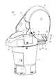
図3は、氷柱の付着した図1に示した監視カメラの斜視図である。 FIG. 3 is a perspective view of the surveillance camera shown in FIG. 1 to which an icicle is attached.
監視カメラ100は、第1チルト軸T1c及び第2チルト軸T2cの少なくとも一方を中心としたチルトハウジング15のチルト回転駆動により、ひさし55が前側外表面部35に接近して、ひさし55に付着した障害物の一例としての氷柱69を除去(例えば破砕)する。 In the
図4は、チルト回転駆動により氷柱を前側外表面部に当てた状態の監視カメラの斜視図である。 FIG. 4 is a perspective view of a surveillance camera in a state where the icicle is in contact with the front outer surface portion by tilt rotation drive.
監視カメラ100では、チルトハウジング15が、第1チルト軸T1c及び第2チルト軸T2cの少なくとも一方を中心としてチルト回転駆動されると、チルトハウジング15のひさし55がパンハウジング13の前側外表面部35に接近する。 In the
図5は、前側外表面部により氷柱が除去された監視カメラの斜視図である。 FIG. 5 is a perspective view of the surveillance camera from which the icicles have been removed by the front outer surface portion.
ひさし55が前側外表面部35に接近すると、ひさし55から突出する方向に付着していた氷柱69が、前側外表面部35に当接し、前側外表面部35からの反力により破砕される。この際、チルトハウジング15は、ひさし55が前側外表面部35へ接近離間するように、チルト回転駆動が正逆回転により繰り返されることがより好ましい。 When the
この監視カメラ100では、パンハウジング13の一部分(前側外表面部35)が、氷柱69を破砕するための構成部材として用いられる。この前側外表面部35とチルト回転駆動とを利用して、付属部品を追加せずに氷柱69を最も経済的にかつ効率よく除去することができる。 In this
特に、監視カメラ100では、チルトハウジング15が、第1チルト軸T1c及び第2チルト軸T2cにより前傾姿勢となるので、ほぼ直下位置となる前側外表面部35へもひさし55を近接させることができる。これにより、氷柱69の効率的な除去がより確実に可能となる。 In particular, in the
(実施の形態2)
次に、実施の形態2に係る監視カメラの例について説明する。(Embodiment 2)
Next, an example of the surveillance camera according to the second embodiment will be described.
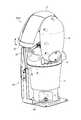
図6は、実施の形態2に係る監視カメラの斜視図である。 FIG. 6 is a perspective view of the surveillance camera according to the second embodiment.
実施の形態2に係る監視カメラ200は、前側外表面部35の前方に、パン旋回方向に沿って延在する当接棒71を有した門型の障害物除去部材の一例としての氷柱破砕部材73が配置される。氷柱破砕部材73は、上向き屈曲部を有するL型の平行な支持棒75が、本体ハウジング11に固定される。この一対の支持棒75の上向き屈曲部に当接棒71の両端が支持される。これにより、当接棒71は、前側外表面部35の前方に配置される。当接棒71は、パン旋回円に沿う円弧形状であってもよく、パン旋回円の接線に沿う直線形状であってもよい。 The
図7は、チルト回転駆動により氷柱を門型の氷柱破砕部材に当てた状態の監視カメラの斜視図である。 FIG. 7 is a perspective view of a surveillance camera in a state where the icicle is applied to the gate-shaped icicle crushing member by tilt rotation drive.
この監視カメラ200では、当接棒71が、前側外表面部35よりも更に前側へ離間して配置される。チルトハウジング15が、第1チルト軸T1c及び第2チルト軸T2cの少なくとも一方を中心としてチルト回転駆動されると、チルトハウジング15のひさし55が当接棒71に接近する。 In this
図8は、門型の氷柱破砕部材により氷柱が除去された監視カメラの斜視図である。 FIG. 8 is a perspective view of a surveillance camera in which an icicle is removed by a gate-shaped icicle crushing member.
ひさし55が当接棒71に接近すると、ひさし55から突出する方向に付着していた氷柱69が、当接棒71に当接し、当接棒71からの反力により破砕される。この際、チルトハウジング15は、ひさし55が当接棒71を上下方向で通過して往復動するように、チルト回転駆動が正逆回転方向に繰り返されることがより好ましい。つまり、チルトハウジング15をお辞儀動作させる。 When the
この監視カメラ200によれば、当接棒71が前側外表面部35よりも浮上しているので、氷柱69を前側外表面部35へ直接当てるよりも、小さいチルト回転角度で氷柱69を当接棒71へ当てることが可能となる。また、当接棒71は、パン旋回方向に沿うので、氷柱69に交差する方向で局所的に当てることができ、応力を集中させて氷柱69を破砕し易くできる。 According to this
(実施の形態3)
次に、実施の形態3に係る監視カメラの例について説明する。(Embodiment 3)
Next, an example of the surveillance camera according to the third embodiment will be described.
図9は、実施の形態3に係る監視カメラの斜視図である。 FIG. 9 is a perspective view of the surveillance camera according to the third embodiment.
実施の形態3に係る監視カメラ300は、本体ハウジング11に、パン軸Pcに沿って延在する当接棒77を有したL型の障害物除去部材の一例としての氷柱破砕部材79が突設される。当接棒77は、本体ハウジング11から半径方向外側に突出する支持棒81の突出先端に固定される。 In the
図10は、パン回転駆動により氷柱をL型の氷柱破砕部材に当てた状態の監視カメラの斜視図である。 FIG. 10 is a perspective view of a surveillance camera in a state where the icicle is applied to the L-shaped icicle crushing member by the pan rotation drive.
この監視カメラ300では、当接棒77が、前側外表面部35よりも更に前側へ離間して配置される。チルトハウジング15が、第1チルト軸T1c及び第2チルト軸T2cの少なくとも一方を中心としてチルト回転駆動されると、チルトハウジング15のひさし55が当接棒71に接近する。ひさし55が当接棒71に接近すると、ひさし55から突出する方向に付着していた氷柱69が、当接棒77と交差する向きに近接配置される。この状態で、パンハウジング13がパン回転駆動される。 In the
図11は、L型の氷柱破砕部材により氷柱が除去された監視カメラの斜視図である。 FIG. 11 is a perspective view of a surveillance camera in which an icicle is removed by an L-shaped icicle crushing member.
氷柱69は、パンハウジング13と共にチルトハウジング15がパン回転駆動されると、当接棒77に当接し、当接棒77からの反力により破砕される。この際、チルトハウジング15は、ひさし55が当接棒77を左右方向で通過して往復動するように、パン回転駆動が正逆回転方向に繰り返されることがより好ましい。つまり、チルトハウジング15を左右に首振りさせる。 When the
このL型の氷柱破砕部材79による氷柱69の破砕には、パン回転駆動が利用される。監視カメラ300において、パン駆動装置21は、最も大きな回転トルクを有する。従って、監視カメラ300は、最も強力な破砕力で氷柱69を除去することができる。 Pan rotation drive is used for crushing the
(実施の形態3の変形例)
次に、実施の形態3の変形例に係る監視カメラの例について説明する。(Modified Example of Embodiment 3)
Next, an example of a surveillance camera according to a modified example of the third embodiment will be described.
図12は、実施の形態3の変形例に係る監視カメラの斜視図である。 FIG. 12 is a perspective view of a surveillance camera according to a modified example of the third embodiment.
実施の形態3の変形例に係る監視カメラ300Aは、本体ハウジング11に沿う方向に起立する氷柱破砕部材83を有する。氷柱破砕部材83は、下部に形成された固定板85が、本体ハウジング11を被固定面に固定するボルト17に共締めされて固定される。氷柱破砕部材83は、上部に、パン軸Pcに略直交する方向の当接棒87を有する。また、氷柱破砕部材83は、上下方向の略中間位置が、補強棒89により本体ハウジング11に支持される。これにより、本体ハウジング11に、高強度に固定されている。なお、氷柱破砕部材83は、例えば監視カメラ300Aから、監視カメラ300Aが取り付けられる別体のポール(不図示)への取付部材(不図示)側からアーム(不図示)を延ばして監視カメラ300A(例えば監視カメラ300Aの本体ハウジング11)に固定されても構わない。 The
図13は、パン回転駆動により氷柱を補強材付きのL型の氷柱破砕部材に当てた状態の監視カメラの斜視図である。 FIG. 13 is a perspective view of a surveillance camera in a state where the icicle is applied to an L-shaped icicle crushing member with a reinforcing material by pan rotation drive.
この監視カメラ300Aでは、チルトハウジング15が、第1チルト軸T1c及び第2チルト軸T2cの少なくとも一方を中心としてチルト回転駆動されると、チルトハウジング15のひさし55が当接棒87に接近する。ひさし55が当接棒87に接近すると、ひさし55から突出する方向に付着していた氷柱69が、当接棒87と交差する向きに近接配置される。この状態で、パンハウジング13がパン回転駆動される。 In this
図14は、補強材付きのL型の氷柱破砕部材により氷柱が除去された監視カメラの斜視図である。 FIG. 14 is a perspective view of a surveillance camera in which an icicle is removed by an L-shaped icicle crushing member with a reinforcing material.
氷柱69は、パンハウジング13と共にチルトハウジング15がパン回転駆動されると、当接棒87に当接し、当接棒87からの反力により破砕される。この際、チルトハウジング15は、ひさし55が当接棒87を左右方向で通過して往復動するように、パン回転駆動が正逆回転方向に繰り返されることがより好ましい。つまり、チルトハウジング15を左右に首振りさせる。 When the
このL型の氷柱破砕部材83による氷柱69の破砕には、パン回転駆動が利用される。監視カメラ300Aにおいて、パン駆動装置21は、最も大きな回転トルクを有する。従って、監視カメラ300Aの場合も、最も強力な破砕力で氷柱69を除去することができる。また、氷柱破砕部材83は、パン軸Pcに略直交方向の当接棒87を有するので、パン軸Pcに沿う方向の当接棒77に比べ、小さいチルト回転角度で氷柱69を当接棒87に当てることができる。 Pan rotation drive is used for crushing the
(実施の形態4)
次に、実施の形態4に係る監視カメラの例について説明する。(Embodiment 4)
Next, an example of the surveillance camera according to the fourth embodiment will be described.
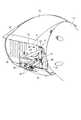
図15は、実施の形態4に係る監視カメラの斜視図である。 FIG. 15 is a perspective view of the surveillance camera according to the fourth embodiment.
実施の形態4に係る監視カメラ400は、ワイパ57に、障害物除去部材の一例としての氷柱破砕部材91が設けられる。氷柱破砕部材91は、ワイパアーム63から光軸Ocに沿う方向でカバーガラス53と反対側に突出する当接棒93を有する。氷柱破砕部材91の当接棒93は、ワイパアーム63の移動によりひさし55に付着した氷柱69を破砕する。 In the
図16は、ワイパアームに設けた当接棒により氷柱が除去される前の監視カメラの要部拡大図である。 FIG. 16 is an enlarged view of a main part of the surveillance camera before the icicles are removed by the contact rod provided on the wiper arm.
この監視カメラ400では、ワイパ57が駆動されると、ワイパアーム63が平行クランク機構61により平行移動される。このワイパアーム63を挟んでカバーガラス53の反対側に、ひさし55が配置される。監視カメラ400は、正置姿勢において、氷柱69がひさし55から鉛直方向下側へ垂下して付着する。 In this
なお、監視カメラ400において、ワイパ駆動軸59とワイパアーム63とは平行クランク機構61を介して接続されているが、平行クランク機構61は省略されても構わない。言い換えると、ワイパ57は、平行クランク機構61を介したワイパアーム63の左右方向の平行移動に基づいて駆動されなくてもよい。この場合には、ワイパ駆動軸59とワイパアーム63とが例えば直付けされ、ワイパ57はワイパ駆動軸59を回転軸とした円弧上に移動する。 In the
図17は、ワイパアームに設けた当接棒により氷柱が除去された後の監視カメラの要部拡大図である。 FIG. 17 is an enlarged view of a main part of the surveillance camera after the icicles have been removed by the contact rod provided on the wiper arm.
氷柱69が付着した状態でワイパアーム63が平行移動されると、ワイパアーム63から前方に突出した当接棒93が、氷柱69に交差する方向で当たり、氷柱69を破砕する。 When the
この監視カメラ400では、パン駆動装置21やチルト駆動装置37を駆動させることなく即座に氷柱69の除去が可能となる。このため、比較的小さな氷柱69を頻繁に除去する場合に好適となる。また、この監視カメラ400では、既存の監視カメラ本体構造は変更せずに、ワイパアーム63の交換のみで簡単に監視カメラに氷柱除去機能を付加することができる。 In this
従って、上述した各実施の形態に係る監視カメラ100、監視カメラ200、監視カメラ300、監視カメラ300A、監視カメラ400によれば、付属部品の増加を抑制しつつ、監視カメラの前面に付着する氷柱69を除去できる。 Therefore, according to the
以上、図面を参照しながら各種の実施の形態について説明したが、本発明はかかる例に限定されないことは言うまでもない。当業者であれば、特許請求の範囲に記載された範疇内において、各種の変更例又は修正例に想到し得ることは明らかであり、それらについても当然に本発明の技術的範囲に属するものと了解される。また、発明の趣旨を逸脱しない範囲において、上述実施の形態における各構成要素を任意に組み合わせてもよい。 Although various embodiments have been described above with reference to the drawings, it goes without saying that the present invention is not limited to such examples. It is clear that a person skilled in the art can come up with various modifications or modifications within the scope of the claims, which naturally belong to the technical scope of the present invention. Understood. Further, each component in the above-described embodiment may be arbitrarily combined as long as the gist of the invention is not deviated.
例えば、上記の構成例では、第1チルト軸及び第2チルト軸を備える構成を説明したが、本発明に係る監視カメラは、第2チルト軸のみによりチルトハウジングがチルト回転駆動されるものであってもよい。即ち、監視カメラは、支持アームが、前傾しなくても上記と同様の効果を奏する。 For example, in the above configuration example, the configuration including the first tilt axis and the second tilt axis has been described, but in the surveillance camera according to the present invention, the tilt housing is tilt-rotated driven only by the second tilt axis. You may. That is, the surveillance camera has the same effect as described above even if the support arm does not tilt forward.
なお、上記の実施の形態2,3において、氷柱破砕部材73,79の当接棒71,77は、それぞれ監視カメラ200,300の通常の旋回時(例えば、パン回転時やチルト回転時)に、監視カメラ200,300の他の部材(例えば、支持アーム19やチルトハウジング15)との衝突を回避可能な位置に設けられてよい。 In the above-described embodiments 2 and 3, the
本開示は、付属部品の増加を抑制しつつ、撮像用のレンズの前面に付着する氷柱を除去できる監視カメラとして有用である。 The present disclosure is useful as a surveillance camera capable of removing icicles adhering to the front surface of an imaging lens while suppressing an increase in accessories.
11…本体ハウジング
13…パンハウジング
15…チルトハウジング
19…支持アーム
35…前側外表面部
51…レンズ
53…カバーガラス
55…ひさし(庇部)
57…ワイパ
63…ワイパアーム
69…氷柱(障害物)
71…当接棒
73…氷柱破砕部材(障害物除去部材)
77…当接棒
79…氷柱破砕部材(障害物除去部材)
83…氷柱破砕部材(障害物除去部材)
87…当接棒
91…氷柱破砕部材(障害物除去部材)
93…当接棒
100、200、300、300A、400…監視カメラ
Oc…光軸
Pc…パン軸
T1c…第1チルト軸
T2c…第2チルト軸11 ...
57 ...
71 ...
77 ...
83 ... Icicle crushing member (obstacle removal member)
87 ...
93 ... Contact
Claims (5)
Translated fromJapanese前記パンハウジングの側部に、基端が支持される支持アームと、
前記支持アームの先端に、前記パン軸に直交するチルト軸により回転駆動自在に支持され、前記チルト軸に直交する方向が光軸となるレンズを有するチルトハウジングと、
前記チルトハウジングに、前記光軸に沿う方向で延出して設けられ、前記レンズへの外乱光の入射を抑制する庇部と、
前記チルト軸を中心とした前記チルトハウジングのチルト回転駆動に基づく前記庇部の接近に応じて、前記庇部に付着した障害物を除去する前記パンハウジングの前側外表面部と、を備える、
監視カメラ。A pan housing that is swiveled around the pan axis and
On the side of the pan housing, a support arm whose base end is supported and
A tilt housing having a lens at the tip of the support arm, which is rotationally driven by a tilt axis orthogonal to the pan axis and whose optical axis is in a direction orthogonal to the tilt axis.
An eaves portion provided in the tilt housing extending in a direction along the optical axis to suppress the incident of ambient light on the lens, and an eaves portion.
A front outer surface portion of the pan housing that removes obstacles adhering to the eaves portion in response to the approach of the eaves portion based on the tilt rotation drive of the tilt housing about the tilt axis.
Surveillance camera.
前記パンハウジングの側部に、前記パン軸に直交する第1チルト軸により基端が回転駆動自在に支持される支持アームと、
前記支持アームの先端に、前記第1チルト軸と同方向の第2チルト軸により回転駆動自在に支持され、前記第2チルト軸に直交する方向が光軸となるレンズを有するチルトハウジングと、
前記チルトハウジングに、前記光軸に沿う方向で延出して設けられ、前記レンズへの外乱光の入射を抑制する庇部と、
前記第1チルト軸及び前記第2チルト軸の少なくとも一方を中心とした前記チルトハウジングのチルト回転駆動に基づく前記庇部の接近に応じて、前記庇部に付着した障害物を除去する前記パンハウジングの前側外表面部と、を備える、
監視カメラ。A pan housing that is swiveled around the pan axis and
On the side of the pan housing, a support arm whose base end is rotatably supported by a first tilt axis orthogonal to the pan axis, and
A tilt housing having a lens at the tip of the support arm, which is rotationally driven by a second tilt axis in the same direction as the first tilt axis and whose optical axis is in a direction orthogonal to the second tilt axis.
An eaves portion provided in the tilt housing extending in a direction along the optical axis to suppress the incident of ambient light on the lens, and an eaves portion.
The pan housing that removes obstacles adhering to the eaves in response to the approach of the eaves based on the tilt rotation drive of the tilt housing centered on at least one of the first tilt axis and the second tilt axis. With the front outer surface of the
Surveillance camera.
請求項2に記載の監視カメラ。A gate-shaped obstacle removing member extending along the pan turning direction is arranged in front of the front outer surface portion.
The surveillance camera according to claim 2.
前記本体ハウジングに、前記パン軸に沿って延在するL型の障害物除去部材が突設される、
請求項2に記載の監視カメラ。The pan housing is rotatably supported around the pan shaft by a main body housing to which the pan shaft is fixed.
An L-shaped obstacle removing member extending along the pan shaft is projected from the main body housing.
The surveillance camera according to claim 2.
前記レンズを覆うカバーガラスと、
前記カバーガラスを挟んで前記レンズと反対側に前記チルトハウジングから前記レンズの光軸に沿う方向で延出し、前記レンズへの外乱光の入射を抑制する庇部と、
ワイパアームの移動に応じて、前記カバーガラスの外表面を拭くワイパと、
前記ワイパアームから前記光軸に沿う方向で前記カバーガラスと反対側に突出し、前記ワイパアームの移動に応じて、前記庇部に付着した障害物を除去する障害物除去部材と、を備える、
監視カメラ。A tilt housing with a lens and
The cover glass that covers the lens and
An eaves portion that extends from the tilt housing to the side opposite to the lens with the cover glass in the direction along the optical axis of the lens to suppress the intrusion of ambient light onto the lens.
With the wiper that wipes the outer surface of the cover glass according to the movement of the wiper arm,
It is provided with an obstacle removing member that projects from the wiper arm in a direction along the optical axis to the opposite side of the cover glass and removes obstacles attached to the eaves in response to the movement of the wiper arm.
Surveillance camera.
Priority Applications (1)
| Application Number | Priority Date | Filing Date | Title |
|---|---|---|---|
| JP2017038647AJP6774356B2 (en) | 2017-03-01 | 2017-03-01 | Surveillance camera |
Applications Claiming Priority (1)
| Application Number | Priority Date | Filing Date | Title |
|---|---|---|---|
| JP2017038647AJP6774356B2 (en) | 2017-03-01 | 2017-03-01 | Surveillance camera |
Publications (2)
| Publication Number | Publication Date |
|---|---|
| JP2018148277A JP2018148277A (en) | 2018-09-20 |
| JP6774356B2true JP6774356B2 (en) | 2020-10-21 |
Family
ID=63592438
Family Applications (1)
| Application Number | Title | Priority Date | Filing Date |
|---|---|---|---|
| JP2017038647AActiveJP6774356B2 (en) | 2017-03-01 | 2017-03-01 | Surveillance camera |
Country Status (1)
| Country | Link |
|---|---|
| JP (1) | JP6774356B2 (en) |
Families Citing this family (3)
| Publication number | Priority date | Publication date | Assignee | Title |
|---|---|---|---|---|
| CN111988503B (en)* | 2020-08-06 | 2021-11-23 | 杭州海康微影传感科技有限公司 | Deicing method and device applied to photoelectric turntable and electronic equipment |
| CN112637475B (en)* | 2021-01-08 | 2022-08-30 | 林青霞 | Outdoor monitoring device |
| CN113099085A (en)* | 2021-03-30 | 2021-07-09 | 襄阳市雄狮光电科技有限公司 | Million high definition pan-tilt monitoring camera lens |
Family Cites Families (5)
| Publication number | Priority date | Publication date | Assignee | Title |
|---|---|---|---|---|
| JP2004061737A (en)* | 2002-07-26 | 2004-02-26 | Matsushita Electric Ind Co Ltd | Outdoor camera device and hood movement control method provided in the outdoor camera device |
| JP4141771B2 (en)* | 2002-09-05 | 2008-08-27 | 松下電器産業株式会社 | Surveillance camera device |
| JP2006345060A (en)* | 2005-06-07 | 2006-12-21 | Canon Inc | Imaging device |
| GB201103367D0 (en)* | 2011-02-28 | 2011-04-13 | 360 Vision Technology Ltd | Security camera |
| JP6080065B1 (en)* | 2016-03-07 | 2017-02-15 | パナソニックIpマネジメント株式会社 | Camera device |
- 2017
- 2017-03-01JPJP2017038647Apatent/JP6774356B2/enactiveActive
Also Published As
| Publication number | Publication date |
|---|---|
| JP2018148277A (en) | 2018-09-20 |
Similar Documents
| Publication | Publication Date | Title |
|---|---|---|
| JP6774356B2 (en) | Surveillance camera | |
| JP6080061B1 (en) | Imaging device | |
| US8567963B1 (en) | System for a self-cleaning/wiping protective dome integrated into an outdoor camera housing | |
| US6343402B1 (en) | Mirror wiper assembly | |
| KR102294403B1 (en) | Cctv camera with the wiper | |
| CN110103892B (en) | Wiper system for vehicle | |
| KR20160071289A (en) | Apparatus for cleaning camera sight glass of security camera housing | |
| JP2017163227A (en) | Camera device | |
| JP2004329497A (en) | Spherical housing apparatus | |
| US20190113742A1 (en) | Viewing device for a motor vehicle | |
| CN112584019A (en) | Intelligent road inspection robot | |
| JP2007131300A (en) | Visual confirmation camera mounted vehicle equipped with transparent protector for video camera with fixed type wiper device on roof | |
| CN212980089U (en) | Automatic driving auxiliary device for automobile | |
| CN209756985U (en) | Vehicle-mounted wireless micro camera with retractable roof | |
| JP3471337B2 (en) | Camera housing | |
| US9308865B2 (en) | Vehicle side rear-view mirror assembly having a means for exposing a blind spot | |
| JPH09212758A (en) | Cleaning device for monitor device | |
| JP3010938U (en) | Surveillance camera storage case | |
| CN110525350B (en) | Perception sensor operating system and vehicle | |
| EP1619880A1 (en) | Improved mechanism for rotatable image-taking device | |
| JP2004061737A (en) | Outdoor camera device and hood movement control method provided in the outdoor camera device | |
| JP3352131B2 (en) | Wiper device | |
| CN114300828B (en) | Antenna bracket | |
| CN217135569U (en) | Intelligent building security device based on Internet of things | |
| JP3285183B2 (en) | Wiper device |
Legal Events
| Date | Code | Title | Description |
|---|---|---|---|
| A711 | Notification of change in applicant | Free format text:JAPANESE INTERMEDIATE CODE: A711 Effective date:20190731 | |
| A711 | Notification of change in applicant | Free format text:JAPANESE INTERMEDIATE CODE: A712 Effective date:20191205 | |
| A621 | Written request for application examination | Free format text:JAPANESE INTERMEDIATE CODE: A621 Effective date:20191227 | |
| A977 | Report on retrieval | Free format text:JAPANESE INTERMEDIATE CODE: A971007 Effective date:20200914 | |
| TRDD | Decision of grant or rejection written | ||
| A01 | Written decision to grant a patent or to grant a registration (utility model) | Free format text:JAPANESE INTERMEDIATE CODE: A01 Effective date:20200923 | |
| A61 | First payment of annual fees (during grant procedure) | Free format text:JAPANESE INTERMEDIATE CODE: A61 Effective date:20201002 | |
| R150 | Certificate of patent or registration of utility model | Ref document number:6774356 Country of ref document:JP Free format text:JAPANESE INTERMEDIATE CODE: R150 | |
| S111 | Request for change of ownership or part of ownership | Free format text:JAPANESE INTERMEDIATE CODE: R313111 | |
| R350 | Written notification of registration of transfer | Free format text:JAPANESE INTERMEDIATE CODE: R350 | |
| S531 | Written request for registration of change of domicile | Free format text:JAPANESE INTERMEDIATE CODE: R313531 | |
| S533 | Written request for registration of change of name | Free format text:JAPANESE INTERMEDIATE CODE: R313533 | |
| R350 | Written notification of registration of transfer | Free format text:JAPANESE INTERMEDIATE CODE: R350 | |
| R250 | Receipt of annual fees | Free format text:JAPANESE INTERMEDIATE CODE: R250 | |
| R250 | Receipt of annual fees | Free format text:JAPANESE INTERMEDIATE CODE: R250 | |
| R250 | Receipt of annual fees | Free format text:JAPANESE INTERMEDIATE CODE: R250 |