JP6773473B2 - Survey information management device and survey information management method - Google Patents
Survey information management device and survey information management methodDownload PDFInfo
- Publication number
- JP6773473B2 JP6773473B2JP2016149398AJP2016149398AJP6773473B2JP 6773473 B2JP6773473 B2JP 6773473B2JP 2016149398 AJP2016149398 AJP 2016149398AJP 2016149398 AJP2016149398 AJP 2016149398AJP 6773473 B2JP6773473 B2JP 6773473B2
- Authority
- JP
- Japan
- Prior art keywords
- point
- dimensional
- camera
- image data
- stereo image
- Prior art date
- Legal status (The legal status is an assumption and is not a legal conclusion. Google has not performed a legal analysis and makes no representation as to the accuracy of the status listed.)
- Active
Links
Images


Landscapes
- Length Measuring Devices By Optical Means (AREA)
- Measurement Of Optical Distance (AREA)
Description
Translated fromJapanese本発明は、測量情報管理装置および測量情報管理方法に関する。 The present invention relates to a survey information management device and a survey information management method.
従来、建物の位置を測量するためには、担当者が現場に行き、測量基材を用いて計測する必要があった。また、道路周辺設備の位置の測量には、MMS(Mobile Mapping System、モービルマッピングシステム)を利用した計測等がなされている。
ここで、MMSとは、高精度な3次元位置情報を取得するシステムである。MMSは、カメラ、レーザースキャナ、GPS(Global Positioning System)、オドメータおよびIMU(Inertial Measurement Unit、慣性計測装置)等の機器を搭載した車両を走行させながら、それぞれの機器を用いてデータを取得する。そして、MMSは、カメラで撮像した画像情報にレーザースキャナで取得した道路周辺設備の位置座標等を重ねあわせ、さらにGPSで等から取得した車両位置、進行方向等の情報を用いて補正等を行う。こうして取得されるMMS参照データは、誤差10cm程度という、高い精度をもつ。
特許文献1によれば、GPSの電波が届かない場合であっても、位置座標値が予め分かっている地物(ランドマーク)等を利用することで、精度を高く維持する。In the past, in order to measure the position of a building, it was necessary for the person in charge to go to the site and measure using a surveying base material. In addition, the position of the equipment around the road is measured by using MMS (Mobile Mapping System, mobile mapping system).
Here, MMS is a system that acquires highly accurate three-dimensional position information. The MMS acquires data using each device while traveling a vehicle equipped with devices such as a camera, a laser scanner, a GPS (Global Positioning System), an odometer, and an IMU (Inertial Measurement Unit). Then, the MMS superimposes the position coordinates of the road peripheral equipment acquired by the laser scanner on the image information captured by the camera, and further corrects the vehicle position, the traveling direction, etc. acquired from GPS or the like. .. The MMS reference data acquired in this way has a high accuracy of about 10 cm.
According to Patent Document 1, even when GPS radio waves do not reach, high accuracy is maintained by using a feature (landmark) whose position coordinate value is known in advance.
しかしながら、MMSは、高い精度を実現するために各種機器を用いるので、装置コストが高い。また、MMSは、多数の機材を搭載するだけでなく、これらの機材が情報を取得するタイミングを、厳密に管理し同期させることを要する。このため、高度なタイミング管理を実現させる制御装置も必要となる。
道路周辺設備の測量にあたっては、設備の保守・点検(メンテナンス)のために、定期的に測量を繰り返す必要がある。しかし、装置コストの高いMMSを利用した測量を、繰り返し行えば膨大な費用がかかってしまう。
一方、MMSを用いずに安価に測量を行うために、車載したGPSによる位置情報およびカメラで撮像した画像情報を用いて、位置合わせを行うことが考えられる。しかし、車載のGPSの位置情報の精度が、MMSの用いるGPSより大幅に低いために、測量精度が低下してしまう。However, since MMS uses various devices to realize high accuracy, the device cost is high. In addition, MMS is required not only to mount a large number of devices, but also to strictly manage and synchronize the timing at which these devices acquire information. Therefore, a control device that realizes advanced timing management is also required.
When surveying equipment around roads, it is necessary to repeat the survey on a regular basis for equipment maintenance and inspection (maintenance). However, if the survey using MMS, which has a high equipment cost, is repeated, a huge cost will be incurred.
On the other hand, in order to carry out the survey at low cost without using MMS, it is conceivable to perform the positioning by using the position information by the GPS mounted on the vehicle and the image information captured by the camera. However, since the accuracy of the position information of the in-vehicle GPS is significantly lower than that of the GPS used by the MMS, the survey accuracy is lowered.
本発明は、このような事情に鑑みてなされたもので、その目的は、MMSを用いずに取得した測量情報を、MMSを用いた場合と同等の精度の測量情報に補正する測量情報管理装置および測量情報管理方法を提供することにある。 The present invention has been made in view of such circumstances, and an object of the present invention is a surveying information management device that corrects surveying information acquired without using MMS to surveying information with the same accuracy as when using MMS. And to provide a survey information management method.
上述した課題を解決するために、本発明にかかる測量情報管理装置は、移動体に設けた2個の撮像装置の各々から得た視差を有する2枚の画像データから、移動体周辺における観察対象3次元形状を含む3次元空間であるステレオ画像を生成する画像生成部と、前記撮像装置の各々により撮像された位置を示す位置情報を取得する位置情報取得部と、前記ステレオ画像における3次元位置情報を示すステレオ画像データ、およびモービルマッピングシステムにより予め取得されたMMS参照データであって、前記位置情報に相当する位置の周辺の3次元位置情報を示すMMS参照データに、共通に存在する3次元形状の同一箇所を示す点を選択し、前記MMS参照データにおいて前記選択された点に対応する点を基準点とし、前記ステレオ画像データにおける前記選択された点の3次元座標が、前記基準点の3次元座標となるように補正する補正部と、を備えること。
In order to solve the above-mentioned problems, the survey information management device according to the present invention is an observation target around the moving body from two image data having a parallax obtained from each of the two imaging devices provided on the moving body. An image generation unit that generates a stereo image that is a three-dimensional space including a three-dimensional shape,a position information acquisition unit that acquires position information indicating a position imaged by each of the imaging devices, and athree-dimensional position in the stereo image. The stereo image data indicating the information and the MMS reference data previously acquired by the mobile mapping system, which are commonly present in the three-dimensional MMS reference data indicating the three-dimensional position information around the position corresponding to the position information. A point indicating the same location in the shape is selected, the point corresponding to the selected point in the MMS reference data is set as a reference point, and the three-dimensional coordinates of the selected point in the stereo image data are the reference points. Provided with a correction unit that corrects the coordinates so that the coordinates arethree-dimensional .
また、上述した課題を解決するために、この発明に係る測量情報管理方法は、移動体に設けた2個の撮像装置の各々から得た視差を有する2枚の画像データから、移動体周辺における観察対象3次元形状を含む3次元空間であるステレオ画像を生成するステップと、前記撮像装置の各々により撮像された位置を示す位置情報を取得するステップと、前記ステレオ画像における3次元位置情報を示すステレオ画像データ、およびモービルマッピングシステムにより予め取得されたMMS参照データであって、前記位置情報に相当する位置の周辺の3次元位置情報を示すMMS参照データに、共通に存在する3次元形状の同一箇所を示す点を選択し、前記MMS参照データにおいて前記選択された点に対応する点を基準点とし、前記ステレオ画像データにおける前記選択された点の3次元座標が、前記基準点の3次元座標となるように補正するステップと、を備える。Further, in order to solve the above-mentioned problems, the survey information management method according to the present invention is performed in the vicinity of the moving body from two image data having a parallax obtained from each of the two imaging devices provided on the moving body. The step of generating a stereo image which is a three-dimensional space including the three-dimensional shape of the observation target, the stepof acquiring the position information indicating the position imaged by each of the imaging devices, and thethree-dimensional position information in the stereo imageare shown. The stereo image data and the MMS reference data acquired in advance by the mobile mapping system, which have the same three-dimensional shape that are commonly present in the MMS reference data indicating the three-dimensional position information around the position corresponding to the position information. A point indicating a location is selected, the point corresponding to the selected point in the MMS reference data is used as a reference point, and the three-dimensional coordinates of the selected point in the stereo image data are the three-dimensional coordinates of the reference point. It is provided with a step of correcting so as to be.
以上説明したように、本発明にかかる測量情報管理装置によれば、MMSを用いずに取得した測量情報を、MMSを用いた場合と同等の精度に補正することができる。こうすることにより、少ないコストで高精度な測量情報を得られる。 As described above, according to the survey information management device according to the present invention, the survey information acquired without using MMS can be corrected with the same accuracy as when MMS is used. By doing so, highly accurate survey information can be obtained at low cost.
<第1の実施形態>
以下、本発明の第1の実施形態による測量情報管理装置について、図面を参照して説明する。
図1は、この発明の一実施形態による測量情報管理装置が用いられる状況の一例を示す概要図である。本発明にかかる測量情報管理装置は、例えば、移動体である車両13に設けられた取得部10と、データ管理センター16内に設けられる管理部20とを含んで構成される。
本発明にかかる測量情報管理装置は、例えば、車両13周辺における観察対象である、道路12および道路周辺設備から成る、道路周辺環境1の測量データの収集に用いられる。道路周辺設備は、例えば、マンホール14および、電柱15等である。道路12では、本発明にかかる測量情報管理装置に備えられる取得部10を搭載した車両13が、道路周辺環境1のマンホール14等の3次元形状を含む3次元空間であるステレオ画像データを撮像するために走行する。
取得部10は、車両13の走行中に、定期的に、道路12の周囲にある、マンホール14や電柱15等の道路周辺設備を含む、道路周辺環境1の画像データを取得する。
また、本発明にかかる測量情報管理装置に備えられる管理部20は、取得部10が取得した画像データを管理する。管理部20は、MMSを用いて取得した3次元位置情報(以下、MMS参照データと称する。)が記録されている。そして、管理部20は、MMS参照データを用いて、取得部10が取得した画像データに基づいて求められる3次元形状を含む3次元空間に関する情報を補正し管理する。<First Embodiment>
Hereinafter, the surveying information management device according to the first embodiment of the present invention will be described with reference to the drawings.
FIG. 1 is a schematic diagram showing an example of a situation in which a surveying information management device according to an embodiment of the present invention is used. The survey information management device according to the present invention includes, for example, an
The survey information management device according to the present invention is used, for example, to collect survey data of the road peripheral environment 1 composed of the
While the
Further, the
図2は、本実施形態における、測量情報管理装置の構成を示す概略ブロック図である。図2を用いて、本実施形態における測量情報管理装置の各構成要素について説明する。
本実施形態における測量情報管理装置は、取得部10および管理部20を備える。また、取得部10は、撮像制御部111と、カメラ112およびカメラ113と、GPS受信機114と、画像データ記録領域122とを備える。管理部20は、処理部201と、記録部202とを備える。FIG. 2 is a schematic block diagram showing the configuration of the survey information management device in the present embodiment. Each component of the surveying information management device according to the present embodiment will be described with reference to FIG.
The survey information management device in the present embodiment includes an
取得部10は、車両13に搭載される。
取得部10は、撮像制御部111に、GPS受信機114、カメラ112およびカメラ113制御させることで、車両13が走行している、道路周辺の画像データを取得する。
撮像制御部111は、カメラ112およびカメラ113に、道路周辺の画像を撮像させる。また、撮像制御部111は、GPS受信機114に、カメラ112およびカメラ113が画像データを取得した場所の位置情報を取得させる。
撮像制御部110は、GPS受信機114、カメラ112およびカメラ113から取得した、位置情報および画像データを、両者を関連付け、画像データ記録領域に記録させる。
撮像制御部111は、画像データを取得するタイミングを示す信号(以下、タイミング信号とも称する。)を、カメラ112およびカメラ113に、同時に送信する。これは、カメラ112およびカメラ113から得られる、2枚の画像データから、いわゆるステレオ画像を生成できるようにするためである。また、撮像制御部111は、GPS受信機114が位置情報を取得するタイミングが、カメラ112およびカメラ113が画像データを取得するタイミングと同時になるように制御する。このように、撮像制御部111は、道路周辺を撮像した画像データおよび撮像位置についての情報を取得する。The
The
The image
The image pickup control unit 110 associates the position information and the image data acquired from the
The image
撮像制御部111は、一定の距理を車両13が走行する毎に、GPS受信機114、カメラ112およびカメラ113に対して、タイミング信号を送信する。撮像制御部111は、例えば、GPS受信機114からの情報に基づいて、車両13が走行する距理を把握する。撮像制御部111は、例えば、マイコン(マイクロコンピュータ)または、中央処理装置(いわゆるCPU)等からなる。そして、撮像制御部111は、記憶領域(図示せず)に記録された制御プログラムを読み込んで実行することにより、上述した処理を実行する。
撮像制御部110は、カメラ112およびカメラ113を起動させ、同期して撮影させるトリガー信号として、例えば、CPUデバイスの処理クロックの所定回数毎に生成した一定間隔時間で発生する、ハードウェア的なタイミング信号を用いる。
また、車両には、トランスミッションの出力軸またはタイヤの回転速度に比例した時間間隔にて車速パルスを出力する車速センサが搭載され、この車速パルスが、通常GPS受信機114に取り込まれる。このことから、撮像制御部110は、車速パルスを取得して積分し、一定距離を走行したことを示すタイミング信号を生成する。撮像制御部110は、こうして生成したタイミング信号を、カメラ112およびカメラ113に対して送信し、これらカメラに対し同時に起動撮影を行わせる構成としても良い。The image
The image pickup control unit 110 activates the
Further, the vehicle is equipped with a vehicle speed sensor that outputs a vehicle speed pulse at a time interval proportional to the output shaft of the transmission or the rotation speed of the tire, and the vehicle speed pulse is usually taken into the
カメラ112およびカメラ113は、撮像装置であり、例えば、車両の上部やルームミラーを挟んだ両脇に並んで設置される。また、カメラ112およびカメラ113は、車両13の進行方向前方の景色にある道路付帯設備を含めた領域が撮像できるような方向で設置される。カメラ112およびカメラ113は、同じ領域を左右異なる位置から同時に撮像する。こうすることで、カメラ112およびカメラ113は、左右異なる位置から、道路周辺の画像データを取得する。
こうして得られる、カメラ112およびカメラ113からの2枚の画像データは、視差を有しており、同じ領域が撮像されている。この視差を用いることで、撮像された領域にある撮像対象物を立体視することができる。The
The two image data from the
また、カメラ112およびカメラ113は、撮像制御部111からタイミング信号を受信すると、それぞれの受信時の位置における画像を撮像する。そして、カメラ112およびカメラ113は、画像を撮像することで得られた画像データを、撮像制御部110に送信する。
また、カメラ112およびカメラ113は、ステレオカメラであってもよい。その場合、撮像制御部111は、カメラ112およびカメラ113の撮像タイミングを同期させる必要はない。この場合、撮像制御部111は、ステレオカメラに対して、定期的に撮像タイミングを通知する信号を送信する。When the
Further, the
画像データ記録領域122は、カメラ112およびカメラ113が撮像した画像の画像データと、その画像を取得した位置の情報とが記録される記憶領域である。
画像データ記録領域122は、可搬型記録媒体(例えば、SD(Secure digital)カード等)または、可搬型ではない記録媒体(例えば、ハードディスク等)を有して構成される。また、画像データ記録領域122は、管理部20内の記憶手段の一部であってもよい。この場合、撮像制御部111は、無線等の通信手段を介して、画像データ記録領域122に記録させる画像データ等を、管理部20に送信する。The image
The image
管理部20は、取得部10が取得した測量に関する情報の管理を行う。管理部20は、処理部201および、記録部202を備える。
処理部201は、例えば、ステレオ画像処理部210と、補正部211と、入力部212と、表示部213とを備える。
ステレオ画像処理部210は、取得部10が取得した2枚の画像の画像データから、撮像面の座標上の3次元情報(以下、ステレオ画像データと称する。)を算出する。
ステレオ画像処理部210は、それぞれの画像データにおける同一の撮像対象物の、それぞれの画像座標における位置の関係を求める。そうすることで、ステレオ画像処理部210は、その撮像された領域の3次元形状の立体的な空間情報(3次元座標系における位置情報)が算出できる。その結果、ステレオ画像処理部210は、カメラ112およびカメラ113が撮像した画像データから、それらの画像データに撮像された撮像対象物である、道路周辺環境1の3次元情報を得る。
ステレオ画像処理部210は、算出したステレオ画像データを、補正部211に送信する。
補正部211は、ステレオ画像データ210より、ステレオ画像データを受信する。また、補正部211は、参照データ記録領域222より、世界座標系で示されているMMS参照データを読み込む。そして、補正部211は、ステレオ画像データに対して、ステレオ画像データに撮像された撮像対象物の所定の箇所に対応する、地上面の座標点である3次元情報(以下、3次元情報と称する。)を算出する。補正部211は、算出した3次元情報を、3次元データ記録領域221に書き込み、記録させる。
補正部211は、ステレオ画像データに撮像された撮像対象物の所定の箇所以外の箇所について3次元情報を算出するために、MMS参照データおよび、カメラ撮像面と地表面の幾何学的な条件から、カメラの回転量等算出する。そして、補正部211は、算出したカメラの回転量等を用いて、3次元情報を補正する。補正部211が行う、3次元情報の算出および補正処理については、後述する。
補正部211は、上記3次元情報を得るために、入力部212より、ステレオ画像データ上の選択点情報を取得する。また、補正部211は、入力部より、ステレオ画像データ上の選択点に対応する、MMS参照データ上の対応点情報を取得する。
また、補正部211は、表示部213に、ステレオ画像データおよびMMS参照データを表示させる。こうすることで、例えば、操作者に、表示部213の表示を確認させた上で、上記ステレオ画像データ上の選択点およびMMS参照データ上の対応点を、入力部212から入力させることができる。The
The
The stereo
The stereo
The stereo
The
The
The
Further, the
入力部212は、例えば、マウスおよびキーボード等の外部入力装置を含んで構成される。そして、入力部212は、表示部213が表示する画像の、任意の地点を示す信号を、補正部211に送信する。 The
表示部213は、補正部211からの制御に基づいて、ステレオ画像データおよびMMS参照データに基づく画像をする。
表示部213は、例えば、液晶ディスプレイ、有機EL(Electroluminescence)ディスプレイ、等を有する。表示部213は、複数の表示装置で、ステレオ画像データおよび、MMS参照データを別々に表示するようにしてもよいし、1の表示装置で、これらの画像を並べて表示するようにしてもよい。The
The
記録部202は、内部の記録媒体に、3次元情報および、MMS参照データを記録させる。記録部202は、例えば、3次元データ記録領域221と、参照データ記録領域222とを備える。
3次元データ記録領域221は、補正部211が算出した、3次元情報を記録させるための記録領域である。参照データ記録領域222は、MMS参照データが記録されるための記録領域である。The
The three-dimensional
<3次元情報算出およびその補正処理>
ここでは、図3を用いて、補正部211が、ステレオ画像データおよび、MMS参照データを用いて、ステレオ画像データの3次元情報を算出および補正する方法について説明する。図3は、空中から地上を撮影した場合の位置関係を示す模式図である。
図3(a)は、カメラの撮像面(例えば、カメラ112で撮像した撮像面)と、地上面との位置関係を示す。主点Oはレンズの中心、地物Pは地上面にある任意の点、像点pは地物Pが撮像面に投影された像点、をそれぞれ示している。
図3(a)に示す通り、主点Oから、地上面と反対方向に、焦点距離f離れて、実際の撮像面がある。ここでは、説明を簡単にするために、主点Oから、地上面方向にf移動した座標を中心として撮像面があるとみなして(図3(a)において「見なし撮像面」と称している。)説明する。以下の説明では、みなし撮像面のことを、単に、撮像面と称する。
図3(b)は、図3(a)をXZ断面および、YZ断面からみた図を示す。
図3(c)は、図3(a)における各点の撮像面座標系(図3(c)において、カメラ座標系と称している。)および地上座標系における、それぞれの座標を示す。<Three-dimensional information calculation and its correction processing>
Here, a method in which the
FIG. 3A shows the positional relationship between the image pickup surface of the camera (for example, the image pickup surface imaged by the camera 112) and the ground surface. The principal point O is the center of the lens, the feature P is an arbitrary point on the ground surface, and the image point p is the image point where the feature P is projected on the imaging surface.
As shown in FIG. 3A, there is an actual imaging surface at a focal length f away from the principal point O in the direction opposite to the ground surface. Here, for the sake of simplicity, it is assumed that there is an imaging surface centered on the coordinates f-moved from the principal point O toward the ground surface (referred to as "deemed imaging surface" in FIG. 3A). .)explain. In the following description, the deemed imaging surface is simply referred to as an imaging surface.
FIG. 3B shows a view of FIG. 3A as viewed from an XZ cross section and a YZ cross section.
FIG. 3 (c) shows the coordinates of each point in FIG. 3 (a) in the imaging plane coordinate system (referred to as the camera coordinate system in FIG. 3 (c)) and the horizontal coordinate system.
まず、空中から地上を撮影した場合で、カメラの傾きがなく、地表面とカメラが平行であると仮定した、簡単なモデルについて、説明する。
図3(a)に示すように、主点Oから、鉛直方向下向きに引いた直線と、地上面との交点をO´とする。また、撮像面の中心を、o´とする。
図3(c)に示すように、地上座標系における、主点O、像点p、地物Pのそれぞれの座標を、(X0、Y0、Z0)、(Xp、Yp、Zp)、(X,Y、Z)とする。また、撮像面上の座標(以下、カメラ座標と称する。)における、主点O、像点p、地物Pのそれぞれの座標を、(0,0,0)、(x、y、-f)、(xP、yP、zP)とする。
このとき、図3(b)に示すように、図3(a)をXZ断面および、YZ断面からみた、三角形OO´Pおよび、三角形Oo´pは、相似する。このため、以下の(1)および(2)式で示す関係がある。First, a simple model will be described in which the ground is photographed from the air, the camera is not tilted, and the ground surface and the camera are assumed to be parallel.
As shown in FIG. 3A, the intersection of the straight line drawn downward in the vertical direction from the principal point O and the ground surface is defined as O'. The center of the imaging surface is o'.
As shown in FIG. 3C, the coordinates of the principal point O, the image point p, and the feature P in the horizontal coordinate system are set to (X0 , Y0 , Z0 ), (Xp , Yp , Zp ), (X, Y, Z). Further, the coordinates of the principal point O, the image point p, and the feature P in the coordinates on the imaging surface (hereinafter referred to as camera coordinates) are set to (0, 0, 0), (x, y, -f). ), (XP , yP , zP ).
At this time, as shown in FIG. 3B, the triangles OO'P and the triangles Oo'p as seen from the XZ cross section and the YZ cross section of FIG. 3A are similar. Therefore, there is a relationship shown by the following equations (1) and (2).
Z−Z0:f=X−X0:x …(1)
Z−Z0:f=Y−Y0:y …(2)ZZ0 : f = XX0 : x ... (1)
ZZ0 : f = YY0 : y ... (2)
上記(1)および(2)式により、xおよびyを求めると、xおよびyの各々は、以下の(3)および(4)式により表せる。 When x and y are obtained from the above equations (1) and (2), each of x and y can be expressed by the following equations (3) and (4).
x=f×(X−X0)/(Z−Z0) …(3)
y=f×(Y−Y0)/(Z−Z0) …(4)x = f × (XX0 ) / (Z-Z0 ) ... (3)
y = f × (Y−Y0 ) / (Z−Z0 )… (4)
次に、カメラの撮像方向が、Z軸と並行でない場合のモデルについて説明する。カメラの撮像方向が、X軸、Y軸、Z軸を中心として、それぞれ(ω、γ、φ)の角度で回転していたとする。この場合、カメラを逆の回転量(−ω、−γ、−φ)で回転させると、図3(a)に示すようなカメラと地表面が平行な関係となる。このとき、このカメラの逆の回転に伴って、撮像面も回転する。このため、xおよびyの各々は、以下の(5)および(6)式でそれぞれ表される。 Next, a model when the imaging direction of the camera is not parallel to the Z axis will be described. It is assumed that the imaging direction of the camera is rotated at angles (ω, γ, φ) about the X-axis, the Y-axis, and the Z-axis. In this case, when the camera is rotated by the opposite rotation amount (−ω, −γ, −φ), the camera and the ground surface are in a parallel relationship as shown in FIG. 3 (a). At this time, the imaging surface also rotates with the reverse rotation of the camera. Therefore, each of x and y is represented by the following equations (5) and (6), respectively.
x=f×A/B …(5)
y=f×C/D …(6)
ただし、上記(5)および(6)式における、A、B、C、Dの各々は、以下の(7)、(8)、(9)、(10)式でそれぞれ表される。
A=a11(X−X0)+a21(Y−Y0)+a31(Z−Z0) …(7)
B=a13(X−X0)+a23(Y−Y0)+a33(Z−Z0) …(8)
C=a12(X−X0)+a22(Y−Y0)+a32(Z−Z0) …(9)
D=a12(X−X0)+a22(Y−Y0)+a32(Z−Z0) …(10)x = f × A / B ... (5)
y = f × C / D ... (6)
However, each of A, B, C, and D in the above equations (5) and (6) is represented by the following equations (7), (8), (9), and (10), respectively.
A = a11 (XX0 ) + a21 (YY0 ) + a31 (ZZ0 ) ... (7)
B = a13 (XX0 ) + a23 (YY0 ) + a33 (ZZ0 ) ... (8)
C = a12 (XX0 ) + a22 (YY0 ) + a32 (ZZ0 ) ... (9)
D = a12 (XX0 ) + a22 (YY0 ) + a32 (ZZ0 ) ... (10)
ここで、上記(7)から(10)式における、a11からa33までの9つの変数は、カメラの回転(ω、γ、φ)の値に基づいて決まる変数である。(5)から(10)式において、既知数は、カメラ座標上の像点p座標(x、y、−f)および、焦点距離fである。また、(5)から(10)式における未知数は、地上座標上の地物P座標(X、Y、Z)、主点O座標(X0、Y0、Z0)およびカメラの回転(ω、γ、φ)の9つである。Here, the above (7) in(10), the nine variables froma 11 toa 33, the rotation of the camera (omega, gamma, phi) is a variable which is determined based on the value of. In the equations (5) to (10), the known numbers are the image point p coordinates (x, y, −f) on the camera coordinates and the focal length f. The unknowns in equations (5) to (10) are the feature P coordinates (X, Y, Z) on the ground coordinates, the principal point O coordinates (X0 , Y0 , Z0 ) and the rotation of the camera (ω). , Γ, φ).
本実施形態においては、車載したカメラから撮影している。このため、カメラは、車両13の進行方向に応じて向きを変えるが、地上からの高さ方向は変化しない。すなわち、X軸およびY軸方向に移動するがZ軸方向には移動しない。このためカメラの回転は(0、0、φ)で表すことができる。
そして、地表上の任意の2点、地物P座標(X、Y、Z)および地物P1座標(X1、Y1、Z1)について、MMS参照データを用いて既知の値を代入する。そして、それぞれに対して、(5)から(10)式で示す方程式を立てる。
そうすると、未知数4に対して、4つの方程式が立てられる。こうすることで、未知数を解くことができる。すなわち、主点O座標(X0、Y0、Z0)およびカメラの回転(0、0、φ)の値が明らかとなる。In this embodiment, the image is taken from an in-vehicle camera. Therefore, the camera changes its direction according to the traveling direction of the
Then, known values are substituted for any two points on the ground surface, the feature P coordinates (X, Y, Z) and the feature P1 coordinates (X1, Y1, Z1) using the MMS reference data. Then, for each, the equations shown by equations (5) to (10) are established.
Then, four equations are established for the unknown number 4. By doing this, the unknown can be solved. That is, the values of the principal point O coordinates (X0 , Y0 , Z0 ) and the rotation of the camera (0, 0, φ) become clear.
この上述した作業をもう一方のカメラ(例えば、カメラ113)に対しても同様に行い、それぞれのカメラの、主点O座標およびカメラの回転を求める。そして、ステレオ画像処理部210から得られるステレオ画像データにより、撮像面の座標上の3次元情報がえられる。
そのうえで、ステレオ画像処理部210から得られるステレオ画像のカメラ座標系での任意の地点の座標について、(5)から(10)式で示される方程式に代入し、ステレオ画像に映されている任意の地点に対応する地上座標(X、Y、Z)を求めることができる。
すなわち、ステレオ画像データの3次元情報を求めることができる。
以上説明したように、ステレオ画像を生成する2枚の画像の双方に共通に撮像されている像を2点抽出し、各々の像のカメラ座標に対応する地表上の位置座標(緯度経度)を特定する。こうすることで、ステレオ画像上に撮像された他の地点について、3次元情報を算出することができる。The above-mentioned work is performed in the same manner for the other camera (for example, camera 113), and the principal point O coordinate and the rotation of the camera of each camera are obtained. Then, three-dimensional information on the coordinates of the imaging surface can be obtained from the stereo image data obtained from the stereo
Then, the coordinates of an arbitrary point in the camera coordinate system of the stereo image obtained from the stereo
That is, it is possible to obtain three-dimensional information of stereo image data.
As described above, two images that are commonly captured in both of the two images that generate stereo images are extracted, and the position coordinates (latitude and longitude) on the ground surface corresponding to the camera coordinates of each image are obtained. Identify. By doing so, it is possible to calculate three-dimensional information about other points captured on the stereo image.
図4は、本発明における測量情報管理装置で、測量に必要な情報を取得する流れを示すフローチャートである。この図を用いて、測量情報を取得する処理の流れについて説明する。
本フローチャートを説明する前提として、取得部10は、車両13に搭載されている。また、車両13は、測量する道路周辺設備の周辺の道路を走行しているものとする。FIG. 4 is a flowchart showing a flow of acquiring information necessary for surveying in the surveying information management device of the present invention. The flow of the process of acquiring the survey information will be described with reference to this figure.
As a premise for explaining this flowchart, the
取得部10は、測量を開始する場所の付近に到達したら、データの取得を開始する。
まず、撮像制御部111は、GPS受信機114から、最初の位置情報を取得する(ステップS1)。以降、撮像制御部111は、定期的に位置情報を取得し、位置情報の差分から走行距離を算出する。撮像制御部111は、走行距離が所定の値(ここでは2.5m毎)となったら(ステップS2 YES)、情報を取得するためのタイミング信号を、GPS受信機114、カメラ112およびカメラ113へ送信する(ステップS3)。When the
First, the image
カメラ112およびカメラ113は、撮像制御部111からタイミング信号を受信し、それぞれカメラ前景の道路周辺の画像を撮像する。カメラ112および、カメラ113は、取得した画像データを、撮像制御部111に送信する。
また、GPS受信機114は、撮像制御部111からのタイミング信号を受けたら、位置情報を取得し、撮像制御部111に、この位置情報を送信する。
撮像制御部111は、カメラ112およびカメラ113から取得した画像データを、位置情報と関連づけ、画像データ記録領域122に書き込み、記録させる(ステップS4)。
取得部10は、車両13が測量を終了する地点に到着したら、測量に用いるデータの取得を終了する(ステップS5)。そして、本フローチャートは終了する。The
Further, when the
The image
When the
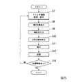
図5は、本発明における測量情報管理装置で取得した画像データから、3次元情報を算出する流れを示すフローチャートである。この図を用いて、3次元情報を取得する処理の流れについて説明する。
本フローチャートを説明する前提として、作業者は、画像データ記録領域122に記録させた画像データを、可搬型記録媒体等に記録させ、データ管理センター16の管理部20のドライブ装置(図示なし)に装着等している。すなわち、取得部10が画像データ記録領域122に記録させた画像データは、管理部20の記録部202から読み取り可能な状態にあるものとする。
まず、ステレオ画像処理部210は、カメラ112およびカメラ113が同時に撮像した2枚の画像の画像データから、ステレオ画像処理を行う。そして、ステレオ画像処理部210は、撮像面座標上の3次元情報である、ステレオ画像データを算出する。ステレオ画像処理部210は、算出したステレオ画像データを、補正部211に送信する。
ステレオ画像処理部210は、画像データに関連づけて記録させている、撮像場所の位置情報を、ステレオ画像データと関連付けて、補正部211に送信する。FIG. 5 is a flowchart showing a flow of calculating three-dimensional information from the image data acquired by the surveying information management device of the present invention. The flow of the process of acquiring the three-dimensional information will be described with reference to this figure.
As a premise for explaining this flowchart, the operator causes the image data recorded in the image
First, the stereo
The stereo
補正部211は、このステレオ画像データを、表示部213に表示させる(ステップS7)。また、補正部211は、ステレオ画像データと関連付けられて送付された、この画像データを取得した位置に関する情報に基づいて、その位置の周辺のMMS参照データを、参照データ記録領域222から読み取る。そして、補正部211は、読み取ったMMS参照データを、表示部213に表示させる(ステップS8)。
操作者は、ステレオ画像データおよびMMS参照データに基づいて表示部213に表示された、2つの画像を視認する。そして、両画像に共通に存在する像である3次元形状の同一箇所を示す点を、入力部212のマウス等を用いて、選択する。さらにもう一点、操作者は、両画像に共通に存在する像の同一箇所を示す点を、選択する。以下の説明では、この選択された点を、選択点とも称する。
入力部212のキーボードのENTERキーが操作者により押下されるなどして、選択点が指定されると、入力部212から、各々の選択点の、画像上の位置を示す信号が、補正部211へ入力される(ステップS9)。
補正部211は、入力部212から取得した選択点の緯度経度を、MMS参照データを用いて、特定する(ステップS10)。
また、補正部211は、ステップS10で算出した2つの選択点の緯度経度に基づいて、カメラ112およびカメラ113の各々の主点座標と回転量を算出する。そして、補正部211は、算出した主点座標および回転量を用いて、ステレオ画像データの選択点以外の任意の点の緯度経度を求める。こうすることで、ステレオ画像データに示されたあらゆる地点の3次元情報を補正する(ステップS11)。
補正部211は、ステップS11で求めた3次元情報を、3次元データ記録領域221に書込んで記録させる(ステップS12)。こうすることで、管理部20は、3次元情報を管理する。
補正部211は、取得部10が取得した画像すべてについて3次元情報を求めるまで、ステップS7に戻り、処理を繰り返す(ステップS13 NO)。The
The operator visually recognizes the two images displayed on the
When a selection point is specified by the operator pressing the ENTER key on the keyboard of the
The
Further, the
The
The
以上、説明したとおり、MMS参照データを用いることで、道路周辺のステレオ画像をから、その画像上に示される任意の設備について3次元情報を得ることができる。MMS参照データは、誤差10cm程度という、高い精度をもつ測量情報である。このため、汎用のGPS受信機およびカメラを用いて得られるステレオ画像の3次元情報も、同程度の精度となる。
こうして求めた3次元情報を用いることで、少ないコストで、道路周辺設備の位置の変化が容易に把握でき、かかる道路周辺設備の保守、点検を効率よく行うことができる。
本実施形態では、MMS参照データを用いて3次元情報を算出したが、これに限定されない。補正部211は、MMS参照データに代わって、地図の位置座標を用いることもできる。この場合、参照データ記録領域222には、その地図のデータが記録される。また、この場合、得られる3次元情報の精度は、その地図の精度に依存する。As described above, by using the MMS reference data, it is possible to obtain three-dimensional information about any equipment shown on the stereo image from the stereo image around the road. The MMS reference data is survey information with a high accuracy of about 10 cm. Therefore, the three-dimensional information of the stereo image obtained by using a general-purpose GPS receiver and a camera has the same accuracy.
By using the three-dimensional information obtained in this way, the change in the position of the road peripheral equipment can be easily grasped at a low cost, and the maintenance and inspection of the road peripheral equipment can be efficiently performed.
In the present embodiment, the three-dimensional information is calculated using the MMS reference data, but the present invention is not limited to this. The
<第2の実施形態>
第2の実施形態について説明する。本実施形態は、第1の実施形態と同様に、取得部10および管理部20を備える測量情報管理装置を用いる。
本実施形態では、補正部211は、GPS受信機114が取得した位置情報を用いて、撮像位置およびカメラの方向を算出する。そして、補正部211は、これらを用いて、3次元情報を求める。こうすることで、補正部211は、第1の実施形態で用いた、ステレオ画像データ上の選択点およびその選択点に対応する対応点の数を減らすことができる。<Second embodiment>
A second embodiment will be described. Similar to the first embodiment, the present embodiment uses a survey information management device including an
In the present embodiment, the
すでに説明した通り、(5)から(10)式に示される未知数は、地上座標上の地物P座標(X、Y、Z)、主点O座標(X0、Y0、Z0)およびカメラの回転(ω、γ、φ)である。
本実施形態においては、主点O座標(X0、Y0、Z0)は、GPS受信機114が取得した位置情報と、GPS受信機114とカメラ112およびカメラ113との位置関係から、求めることができる。さらに、カメラの回転(ω、γ、φ)は、GPS受信機114が取得した位置情報の差分により、求められる。これらの値を代入することにより、(5)から(10)式に示される未知数、主点O座標(X0、Y0、Z0)およびカメラの回転(ω、γ、φ)を算出できる。さらに、精度の高い測定点(基準点)がステレオ画像データ上にあれば、これを用いて、主点O座標およびカメラの回転量を、調整することができる。As already explained, the unknowns shown in equations (5) to (10) are the feature P coordinates (X, Y, Z) on the ground coordinates, the principal point O coordinates (X0 , Y0 , Z0 ) and The rotation of the camera (ω, γ, φ).
In the present embodiment, the principal point O coordinates (X0 , Y0 , Z0 ) are obtained from the position information acquired by the
本実施形態は、第1の実施形態と同様に、撮像制御部111は、GPS受信機114を用いて、カメラ112およびカメラ113が画像を撮像した場所の位置情報を取得する。 In the present embodiment, similarly to the first embodiment, the image
補正部211は、取得部10が取得した位置情報の差分を算出する。補正部211は、画像が撮像された位置の情報から、その前の画像が撮像された位置の情報を減算することで、前の画像が撮像された場所からの、移動距離および進行方向を算出する。カメラ112およびカメラ113は車両13の進行方向に対し垂直に設置されているため、補正部211は、この進行方向を、カメラの回転方向とすることができる。
また、補正部211は、ステレオ画像データを、表示部213に表示させる。そして補正部211は、表示部213に表示させたステレオ画像データに示される何らかの基準点を指定した信号を、入力部212から、入力させる。入力部212からの入力は、第1の実施形態と同様に、操作者等がマウスやキーボード等を用いて行う。補正部211は、入力部212から指定された基準点の情報に対し、参照データ記録領域222を参照する等により、その基準点の緯度経度を特定する。
そして、補正部211は、算出した、主点位置とカメラの方向と、特定した基準点の緯度経度とを用いて、ステレオ画像データのあらゆる地点の3次元情報を求める。補正部211は、求めた3次元情報を、3次元データ記憶領域221に書き込んで記録させる。The
Further, the
Then, the
ここでいう、何らかの基準点とは、例えば、位置情報が正確に測定されている距離標(キロポスト)等が考えられる。また、マンホールや道路がカーブする地点等について、例えば、これらの設備を設置した際の緯度経度が記された測量情報が記録されていれば、これらを用いることもできる。
また、補正部211は、1点の基準点の緯度経度について特定できればよく、第1の実施形態で説明したように2点の基準点の緯度経度を特定させる必要がない。これは、MMS参照データがなくとも、ステレオ画像データに、何かしら測量精度の高い地点が少なくとも1点示されていれば、3次元情報を取得できることを意味する。The reference point referred to here may be, for example, a distance marker (kilopost) in which the position information is accurately measured. Further, for manholes, points where roads curve, etc., for example, if survey information in which the latitude and longitude when these facilities are installed is recorded, these can be used.
Further, the
本実施形態においては、基準点の精度および撮像位置の情報の精度が、3次元データの精度に影響する。
基準点の精度は、より精度の高い場所の緯度経度情報を用いることで、3次元情報の精度を高く算出できる。
撮像位置の情報の精度は、GPS受信機の受信精度、受信状況および、情報取得のタイミングのずれ等に依存する。ここで、GPS受信機114は、例えば、汎用GPS受信機である。汎用GPS受信機は、衛星から送信される、周波数の異なった2つの送信波のうち、1波を受信するのみであり、測量用GPS受信機と比較して、誤差が大きい。また、トンネル内部や、高架下など、衛星からの信号が届きにくい場所を、車両13が走行している間、GPS受信機は、十分な台数の衛星からの信号を受信するできないことも考えられる。この場合、GPS受信機から取得する位置情報は、途絶する、または、相応の誤差が含まれることになる。In the present embodiment, the accuracy of the reference point and the accuracy of the imaging position information affect the accuracy of the three-dimensional data.
The accuracy of the reference point can be calculated with high accuracy of the three-dimensional information by using the latitude / longitude information of the place with higher accuracy.
The accuracy of the information of the imaging position depends on the reception accuracy of the GPS receiver, the reception status, the deviation of the information acquisition timing, and the like. Here, the
GPS受信機114から取得する位置情報が、途絶している、または、誤差が含まれている場合、補正部211は、位置情報を補間する。補正部211は、例えば、経路から大きく外れた地点を示す位置情報を用いない。そして、補正部211は、その代わりに前後の位置情報を滑らかにつないだ線上の中間点を位置情報として用いる。本実施形態では、撮像制御部111は、車両が2m走行するごとに位置情報を得る。車両の前後のタイヤの間隔(車軸間距離)は、普通車で2.5m程度である。このため、仮に1点が外れた位置を示した場合、その位置情報は前後の値を滑らかにつないだ線の中間にある位置とする方が、より確からしい。
補正部211は、経路から大きく外れた地点を抽出する処理として、例えば、車両13の走行ルート上に、GPS取新規114が取得した位置情報をプロットした図を、表示部213に表示させる。そして、補正部211は、その表示画面を操作者に視認させ、ルートから外れている部分を特定させ、その部分に関する情報を、入力部212から、入力させる。こうすることで、経路から大きく外れた地点を抽出する。または、補正部211は、位置の変化量を抽出し、しきい値を設け、変化量がしきい値より大きければ、経路から外れた誤差の含まれる位置情報であると認識してもよい。また、誤差が含まれる位置情報が連続する場合などは、走行ルートに沿った方向を、進行方向(カメラ方向)としてもよい。
補正部211は、このようにして、必要に応じて、より確からしいカメラ方向を用いることで、より精度の高い3次元情報を求めることが可能となる。When the position information acquired from the
As a process of extracting a point significantly deviated from the route, the
In this way, the
以上説明したように、仮に、MMS参照データがない場合であっても、ステレオ画像と、その撮像された位置の情報と、ステレオ画像上にある1点の緯度経度を特定することで、3次元情報を算出することができる。
例えば、ステレオ画像上に、キロポスト等の基準点の像があれば、その基準点の位置座標を用いることができる。測量用の基準点およびキロポストは、位置情報が正確に測定されており、キロポストであれば35cmの精度を有する。
基準点およびキロポストは通常、1km毎かそれ以上の間隔で設置されているため、本発明にかかる測量情報管理装置で取得する画像に、2点以上の基準点等が撮像されることは想定しにくい。それでも、第2に実施形態を用いれば、1点の基準点で、3次元情報を得ることができる。As described above, even if there is no MMS reference data, by specifying the stereo image, the information of the captured position, and the latitude and longitude of one point on the stereo image, it is three-dimensional. Information can be calculated.
For example, if there is an image of a reference point such as a kilometer post on a stereo image, the position coordinates of the reference point can be used. The position information of the reference point and the kilometer post for surveying is accurately measured, and the kilometer post has an accuracy of 35 cm.
Since the reference points and kilometer posts are usually installed at intervals of 1 km or more, it is assumed that two or more reference points or the like are captured in the image acquired by the surveying information management device according to the present invention. Hateful. Nevertheless, if the second embodiment is used, three-dimensional information can be obtained at one reference point.
第1の実施形態および第2の実施形態(以下、第1の実施形態および第2の実施形態をまとめて、実施形態と称する。)では、取得部10にGPS受信機114を備えているが、これに限定されない。取得部10は、適切なタイミングで、位置情報を取得できればよく、例えば、車両13に装備されている、カーナビゲーションシステム(いわゆるカーナビ)のGPS情報を、入力部212から入力するようにしてもよい。この場合、入力部は、GPS情報信号を入力させるためのインターフェースを備える。 In the first embodiment and the second embodiment (hereinafter, the first embodiment and the second embodiment are collectively referred to as an embodiment), the
また、取得部10がステレオ画像を生成する2枚の画像を撮像し、管理部20がその2枚の画像の画像データを用いてステレオ画像を生成しているが、これに限定されない。取得部10が、ステレオ画像を生成してもよい。この場合、取得部10は、ステレオ画像処理部210を備える。そして、撮像制御部111は、カメラ112およびカメラ113から画像データを取得すると、その画像データを、ステレオ画像処理部210へ送信する。ステレオ画像処理部210は、画像データを用いて、ステレオ画像データを生成する。そして、ステレオ画像処理部210は、生成したステレオ画像を、撮像制御部111に渡す。撮像制御部111は、受け取ったステレオ画像を、位置情報と関連付けて、画像データ記憶領域122に記録させる。カメラ112およびカメラ113に代えてステレオカメラを用いる場合なども考えられる。この場合、ステレオカメラから、3次元情報を示すステレオ画像データが、撮像制御部111に出力され、位置情報と関連付けて、画像データ記憶領域122に記録される。 Further, the
また、補正部211は、記憶部202にある、参照データ記録領域222に記録されたMMS参照データ等を参照し、ステレオ画像上の選択点の緯度経度を特定しているが、これに限定されない。補正部211は、例えば、インターネット通信網を介して、位置情報を参照し、緯度経度を特定してもよい。この場合、補正部211は、インターネット通信網にアクセスするためのインターフェースを備える。ここで、通信部211が参照する位置情報は、例えば、国土交通省国土地理院が公開する、電子国土基本図(地図情報)等である。 Further, the
さらに、補正部211は、3次元情報を求めるにあたり、第1の実施形態では2点、第2の実施形態では1点の、ステレオ画像上の選択点について緯度経度を特定している。この選択点の数は3次元情報を求めるために最低限必要な数であり、これに限定されるものではない。補正部211は、さらに、ステレオ画像上の別の選択点についても緯度経度を特定して微調整を行い、3次元情報の精度をさらに高めてもよい。
また、補正部211は、補正に用いた選択点についての情報を、記録部202に記録させてもよい。道路周辺設備においては、設備の保守点検のために測量を繰り返し行う。このため、ステレオ画像およびその3次元情報を取得する際に用いた選択点についての情報が蓄積されれば、次回の測定で選択点を、抽出しやすくなる。
さらに、補正部211は、入力部212から、ステレオ画像上の選択点に関する信号を、入力させているが、これに限定されない。補正部211は、例えば、ステレオ画像およびMMS参照データに共通する特徴ある点を、画像認識技術を用いて自動的に抽出してもよい。この場合、補正部211は、画像認識機能を有し、ステレオ画像およびMMS参照データに共通する特徴ある点を抽出する。そして、その選択点に応じた緯度経度をMMS参照データから特定する。Further, in obtaining the three-dimensional information, the
Further, the
Further, the
上述した実施形態における撮像制御、ステレオ画像処理および、補間処理をコンピュータで実現するようにしてもよい。その場合、この機能を実現するためのプログラムをコンピュータ読み取り可能な記録媒体に記録して、この記録媒体に記録されたプログラムをコンピュータシステムに読み込ませ、実行することによって実現してもよい。なお、ここでいう「コンピュータシステム」とは、OSや周辺機器等のハードウェアを含むものとする。また、「コンピュータ読み取り可能な記録媒体」とは、フレキシブルディスク、光磁気ディスク、ROM、CD−ROM等の可搬媒体、コンピュータシステムに内蔵されるハードディスク等の記憶装置のことをいう。さらに「コンピュータ読み取り可能な記録媒体」とは、インターネット等のネットワークや電話回線等の通信回線を介してプログラムを送信する場合の通信線のように、短時間の間、動的にプログラムを保持するもの、その場合のサーバやクライアントとなるコンピュータシステム内部の揮発性メモリのように、一定時間プログラムを保持しているものも含んでもよい。また上記プログラムは、前述した機能の一部を実現するためのものであってもよく、さらに前述した機能をコンピュータシステムにすでに記録されているプログラムとの組み合わせで実現できるものであってもよく、FPGA(Field Programmable Gate Array)等のプログラマブルロジックデバイスを用いて実現されるものであってもよい。 The imaging control, stereo image processing, and interpolation processing in the above-described embodiment may be realized by a computer. In that case, the program for realizing this function may be recorded on a computer-readable recording medium, and the program recorded on the recording medium may be read by the computer system and executed. The term "computer system" as used herein includes hardware such as an OS and peripheral devices. Further, the "computer-readable recording medium" refers to a portable medium such as a flexible disk, a magneto-optical disk, a ROM, or a CD-ROM, or a storage device such as a hard disk built in a computer system. Further, a "computer-readable recording medium" is a communication line for transmitting a program via a network such as the Internet or a communication line such as a telephone line, and dynamically holds the program for a short period of time. It may also include a program that holds a program for a certain period of time, such as a volatile memory inside a computer system that serves as a server or a client in that case. Further, the above program may be for realizing a part of the above-mentioned functions, and may be for realizing the above-mentioned functions in combination with a program already recorded in the computer system. It may be realized by using a programmable logic device such as FPGA (Field Programmable Gate Array).
以上、この発明の実施形態について図面を参照して詳述してきたが、具体的な構成はこの実施形態に限られるものではなく、この発明の要旨を逸脱しない範囲の設計等も含まれる。 Although the embodiments of the present invention have been described in detail with reference to the drawings, the specific configuration is not limited to this embodiment, and the design and the like within a range not deviating from the gist of the present invention are also included.
1…道路周辺環境、10…取得部、12…道路、13…車両、14…マンホール、15…電柱、16…データ管理センター、20…管理部、
111…撮像制御部、112…カメラ、113…カメラ、114…GPS受信機、122…画像データ記録領域、
201…処理部、210…ステレオ画像処理部、211…補正部、212…入力部、213…表示部、202…記録部、221…3次元データ記録領域、222…参照データ記録領域。1 ... Road environment, 10 ... Acquisition department, 12 ... Road, 13 ... Vehicle, 14 ... Manhole, 15 ... Utility pole, 16 ... Data management center, 20 ... Management department,
111 ... Imaging control unit, 112 ... Camera, 113 ... Camera, 114 ... GPS receiver, 122 ... Image data recording area,
201 ... Processing unit, 210 ... Stereo image processing unit, 211 ... Correction unit, 212 ... Input unit, 213 ... Display unit, 202 ... Recording unit, 221 ... Three-dimensional data recording area, 222 ... Reference data recording area.
Claims (6)
Translated fromJapanese前記撮像装置の各々により撮像された位置を示す位置情報を取得する位置情報取得部と、
前記ステレオ画像における3次元位置情報を示すステレオ画像データ、およびモービルマッピングシステムにより予め取得されたMMS参照データであって、前記位置情報に相当する位置の周辺の3次元位置情報を示すMMS参照データに、共通に存在する3次元形状の同一箇所を示す点を選択し、前記MMS参照データにおいて前記選択された点に対応する点を基準点とし、前記ステレオ画像データにおける前記選択された点の3次元座標が、前記基準点の3次元座標となるように補正する補正部と、
を備えることを特徴とする測量情報管理装置。An image generator that generates a stereo image that is a three-dimensional space including the three-dimensional shape of the observation target around the moving body from two image data having parallax obtained from each of the two imaging devices provided on the moving body. ,
A position information acquisition unit that acquires position information indicating a position imaged by each of the image pickup devices, and a position information acquisition unit.
Thestereo image data indicating the three-dimensional position information in the stereo image and the MMS reference data previously acquired by the mobile mapping system and indicating the three-dimensional position information around the position corresponding to the position information. , A point indicating the same location of the three-dimensional shape that exists in common is selected, the point corresponding to the selected point in the MMS reference data is used as a reference point, and the three-dimensional of the selected point in the stereo image data. A correction unit that corrects the coordinates so that they becomethe three-dimensional coordinates of thereference point ,
A surveying information management device characterized by being equipped with.
ことを特徴とする請求項1に記載の測量情報管理装置。The image pickup device is mounted on a vehicle which is a moving body that moves a position where the observation target can take an image.
The surveying information management device according to claim 1.
ことを特徴とする請求項1又は請求項2に記載の測量情報管理装置。The reference point is a coordinate point in theworld coordinate systemobtained by mobile mapping system,
The surveying information management device according to claim 1 or 2, wherein the survey information management device is characterized.
ことを特徴とする請求項1から請求項3のいずれか一項に記載の測量情報管理装置。The reference point is a coordinate value indicated by the latitude and longitude of a predetermined location on the map.
The surveying information management device according to any one of claims 1 to 3, wherein the survey information management device is characterized.
ことを特徴とする請求項1から請求項4のいずれか一項に記載の測量情報管理装置。The reference point is a coordinate value indicated by the latitude and longitude where the distance marker is installed.
The surveying information management device according to any one of claims 1 to 4, wherein the survey information management device is characterized.
前記撮像装置の各々により撮像された位置を示す位置情報を取得するステップと、
前記ステレオ画像における3次元位置情報を示すステレオ画像データ、およびモービルマッピングシステムにより予め取得されたMMS参照データであって、前記位置情報に相当する位置の周辺の3次元位置情報を示すMMS参照データに、共通に存在する3次元形状の同一箇所を示す点を選択し、前記MMS参照データにおいて前記選択された点に対応する点を基準点とし、前記ステレオ画像データにおける前記選択された点の3次元座標が、前記基準点の3次元座標となるように補正するステップと、
を備えることを特徴とする測量情報管理方法。A step of generating a stereo image, which is a three-dimensional space including a three-dimensional shape of an observation target around the moving body, from two image data having parallax obtained from each of two imaging devices provided on the moving body.
A step of acquiring position information indicating a position imaged by each of the image pickup devices, and
Thestereo image data indicating the three-dimensional position information in the stereo image and the MMS reference data previously acquired by the mobile mapping system and indicating the three-dimensional position information around the position corresponding to the position information. , A point indicating the same location of the three-dimensional shape that exists in common is selected, the point corresponding to the selected point in the MMS reference data is used as a reference point, and the three-dimensional of the selected point in the stereo image data. A step of correcting the coordinates so that they becomethe three-dimensional coordinates of thereference point, and
A surveying information management method characterized by being provided with.
Priority Applications (1)
| Application Number | Priority Date | Filing Date | Title |
|---|---|---|---|
| JP2016149398AJP6773473B2 (en) | 2016-07-29 | 2016-07-29 | Survey information management device and survey information management method |
Applications Claiming Priority (1)
| Application Number | Priority Date | Filing Date | Title |
|---|---|---|---|
| JP2016149398AJP6773473B2 (en) | 2016-07-29 | 2016-07-29 | Survey information management device and survey information management method |
Publications (2)
| Publication Number | Publication Date |
|---|---|
| JP2018017652A JP2018017652A (en) | 2018-02-01 |
| JP6773473B2true JP6773473B2 (en) | 2020-10-21 |
Family
ID=61075784
Family Applications (1)
| Application Number | Title | Priority Date | Filing Date |
|---|---|---|---|
| JP2016149398AActiveJP6773473B2 (en) | 2016-07-29 | 2016-07-29 | Survey information management device and survey information management method |
Country Status (1)
| Country | Link |
|---|---|
| JP (1) | JP6773473B2 (en) |
Families Citing this family (3)
| Publication number | Priority date | Publication date | Assignee | Title |
|---|---|---|---|---|
| JP7107392B2 (en)* | 2019-01-11 | 2022-07-27 | 三菱電機株式会社 | Self-positioning device for moving body |
| JP7122984B2 (en)* | 2019-02-22 | 2022-08-22 | 日立Astemo株式会社 | Data synchronizer, in-vehicle system |
| JP7179897B2 (en)* | 2021-03-31 | 2022-11-29 | 株式会社パスコ | Measurement system, information processing device and information processing method |
Family Cites Families (4)
| Publication number | Priority date | Publication date | Assignee | Title |
|---|---|---|---|---|
| US8264537B2 (en)* | 2007-09-28 | 2012-09-11 | The Mainz Group Llc | Photogrammetric networks for positional accuracy |
| JP5303613B2 (en)* | 2011-07-05 | 2013-10-02 | 株式会社五星 | Moving reference point photogrammetry apparatus and method |
| JP5466752B2 (en)* | 2012-11-29 | 2014-04-09 | 株式会社ゼンリンデータコム | Map display device, map display method, and computer program |
| CN104937648A (en)* | 2013-01-25 | 2015-09-23 | 丰田自动车株式会社 | Road Environment Recognition System |
- 2016
- 2016-07-29JPJP2016149398Apatent/JP6773473B2/enactiveActive
Also Published As
| Publication number | Publication date |
|---|---|
| JP2018017652A (en) | 2018-02-01 |
Similar Documents
| Publication | Publication Date | Title |
|---|---|---|
| US11477374B2 (en) | Three dimensional image capture system for imaging building facades using a digital camera, a near-infrared camera, and laser range finder | |
| US12292298B2 (en) | Methods and systems for generating route data | |
| JP6694395B2 (en) | Method and system for determining position relative to a digital map | |
| US9429438B2 (en) | Updating map data from camera images | |
| EP2132530B1 (en) | System and method for position determination | |
| KR101099484B1 (en) | Apparatus and method for generating 3D map modeling data through 3D terrain survey control module | |
| CN102338639B (en) | Information processing device and information processing method | |
| JP5389964B2 (en) | Map information generator | |
| KR100800554B1 (en) | 3D modeling method using laser scanner and camera image information in mobile photogrammetry system | |
| KR101444685B1 (en) | Method and Apparatus for Determining Position and Attitude of Vehicle by Image based Multi-sensor Data | |
| CA2762743C (en) | Updating map data from camera images | |
| US20090262974A1 (en) | System and method for obtaining georeferenced mapping data | |
| JP2019508677A (en) | Control of vehicle components using maps | |
| JP2010541016A (en) | How to capture linear features along a reference line across a surface for use in a map database | |
| KR100822814B1 (en) | Spatial information service method that combines surveying information, GPS geographic information, and real-time video information by using GPS / INS equipment | |
| KR20170094030A (en) | System and Method for providing mapping of indoor navigation and panorama pictures | |
| CN110986888A (en) | Aerial photography integrated method | |
| JP6773473B2 (en) | Survey information management device and survey information management method | |
| KR101409802B1 (en) | System for analysis space information using three dimensions 3d scanner | |
| US20190033487A1 (en) | Method of creating longitudinal section of three-dimensional point group data, and survey data processing device and survey system for the same | |
| KR100469801B1 (en) | System and Method for Real Time Surveying Ground Control Points of Aerial Photograph | |
| Zhao et al. | Updating a digital geographic database using vehicle-borne laser scanners and line cameras | |
| Gonçalves et al. | Mobile mapping system based on action cameras | |
| Chen et al. | Panoramic epipolar image generation for mobile mapping system | |
| Prieto | Road surface structure monitoring and analysis using high precision gps Mobile Measurement Systems (mms) |
Legal Events
| Date | Code | Title | Description |
|---|---|---|---|
| RD02 | Notification of acceptance of power of attorney | Free format text:JAPANESE INTERMEDIATE CODE: A7422 Effective date:20190315 | |
| A621 | Written request for application examination | Free format text:JAPANESE INTERMEDIATE CODE: A621 Effective date:20190415 | |
| A977 | Report on retrieval | Free format text:JAPANESE INTERMEDIATE CODE: A971007 Effective date:20200212 | |
| A131 | Notification of reasons for refusal | Free format text:JAPANESE INTERMEDIATE CODE: A131 Effective date:20200218 | |
| A521 | Request for written amendment filed | Free format text:JAPANESE INTERMEDIATE CODE: A523 Effective date:20200413 | |
| TRDD | Decision of grant or rejection written | ||
| A01 | Written decision to grant a patent or to grant a registration (utility model) | Free format text:JAPANESE INTERMEDIATE CODE: A01 Effective date:20200901 | |
| A61 | First payment of annual fees (during grant procedure) | Free format text:JAPANESE INTERMEDIATE CODE: A61 Effective date:20201001 | |
| R150 | Certificate of patent or registration of utility model | Ref document number:6773473 Country of ref document:JP Free format text:JAPANESE INTERMEDIATE CODE: R150 | |
| R250 | Receipt of annual fees | Free format text:JAPANESE INTERMEDIATE CODE: R250 | |
| R250 | Receipt of annual fees | Free format text:JAPANESE INTERMEDIATE CODE: R250 | |
| S533 | Written request for registration of change of name | Free format text:JAPANESE INTERMEDIATE CODE: R313533 | |
| R350 | Written notification of registration of transfer | Free format text:JAPANESE INTERMEDIATE CODE: R350 | |
| R250 | Receipt of annual fees | Free format text:JAPANESE INTERMEDIATE CODE: R250 |