JP6773028B2 - Blood pressure measuring device - Google Patents
Blood pressure measuring deviceDownload PDFInfo
- Publication number
- JP6773028B2 JP6773028B2JP2017511467AJP2017511467AJP6773028B2JP 6773028 B2JP6773028 B2JP 6773028B2JP 2017511467 AJP2017511467 AJP 2017511467AJP 2017511467 AJP2017511467 AJP 2017511467AJP 6773028 B2JP6773028 B2JP 6773028B2
- Authority
- JP
- Japan
- Prior art keywords
- pressure measuring
- anastomotic
- blood pressure
- blood
- pressure
- Prior art date
- Legal status (The legal status is an assumption and is not a legal conclusion. Google has not performed a legal analysis and makes no representation as to the accuracy of the status listed.)
- Active
Links
- 230000036772blood pressureEffects0.000titleclaimsdescription72
- 210000004204blood vesselAnatomy0.000claimsdescription41
- 230000000747cardiac effectEffects0.000claimsdescription30
- 238000000034methodMethods0.000claimsdescription18
- 230000008569processEffects0.000claimsdescription7
- 230000000737periodic effectEffects0.000claimsdescription3
- 206010005746Blood pressure fluctuationDiseases0.000claims1
- 210000001367arteryAnatomy0.000description19
- 230000003872anastomosisEffects0.000description12
- 210000004369bloodAnatomy0.000description9
- 239000008280bloodSubstances0.000description9
- 238000001631haemodialysisMethods0.000description9
- 230000000322hemodialysisEffects0.000description9
- 230000017531blood circulationEffects0.000description7
- 238000000502dialysisMethods0.000description7
- 230000004872arterial blood pressureEffects0.000description6
- 230000007423decreaseEffects0.000description6
- 210000000245forearmAnatomy0.000description6
- 239000007788liquidSubstances0.000description6
- 210000003462veinAnatomy0.000description6
- 210000001765aortic valveAnatomy0.000description5
- 210000000623ulnaAnatomy0.000description5
- 230000008321arterial blood flowEffects0.000description4
- 230000008602contractionEffects0.000description4
- 238000010586diagramMethods0.000description4
- 230000003836peripheral circulationEffects0.000description4
- 230000006378damageEffects0.000description3
- 239000004744fabricSubstances0.000description3
- 239000000463materialSubstances0.000description3
- 230000002093peripheral effectEffects0.000description3
- 239000004033plasticSubstances0.000description3
- 239000004065semiconductorSubstances0.000description3
- 230000035488systolic blood pressureEffects0.000description3
- 238000009530blood pressure measurementMethods0.000description2
- 210000000988bone and boneAnatomy0.000description2
- 230000008859changeEffects0.000description2
- 238000006243chemical reactionMethods0.000description2
- 230000035487diastolic blood pressureEffects0.000description2
- 230000010339dilationEffects0.000description2
- 239000002184metalSubstances0.000description2
- 239000005060rubberSubstances0.000description2
- 230000035945sensitivityEffects0.000description2
- 229920003002synthetic resinPolymers0.000description2
- 239000000057synthetic resinSubstances0.000description2
- 206010002329AneurysmDiseases0.000description1
- 206010019280Heart failuresDiseases0.000description1
- 208000027418Wounds and injuryDiseases0.000description1
- 210000000709aortaAnatomy0.000description1
- 230000002238attenuated effectEffects0.000description1
- 230000000740bleeding effectEffects0.000description1
- 230000036760body temperatureEffects0.000description1
- 230000037396body weightEffects0.000description1
- 230000004087circulationEffects0.000description1
- 238000004891communicationMethods0.000description1
- 230000000694effectsEffects0.000description1
- 208000014674injuryDiseases0.000description1
- 238000009434installationMethods0.000description1
- 210000003141lower extremityAnatomy0.000description1
- 238000005259measurementMethods0.000description1
- 210000003492pulmonary veinAnatomy0.000description1
- 230000010349pulsationEffects0.000description1
- 229920005989resinPolymers0.000description1
- 239000011347resinSubstances0.000description1
- 230000004044responseEffects0.000description1
- 210000002820sympathetic nervous systemAnatomy0.000description1
- 230000007704transitionEffects0.000description1
- 238000002604ultrasonographyMethods0.000description1
- 238000011144upstream manufacturingMethods0.000description1
- 238000010200validation analysisMethods0.000description1
- XLYOFNOQVPJJNP-UHFFFAOYSA-NwaterSubstancesOXLYOFNOQVPJJNP-UHFFFAOYSA-N0.000description1
Images


Classifications
- A—HUMAN NECESSITIES
- A61—MEDICAL OR VETERINARY SCIENCE; HYGIENE
- A61B—DIAGNOSIS; SURGERY; IDENTIFICATION
- A61B5/00—Measuring for diagnostic purposes; Identification of persons
- A61B5/02—Detecting, measuring or recording for evaluating the cardiovascular system, e.g. pulse, heart rate, blood pressure or blood flow
- A61B5/021—Measuring pressure in heart or blood vessels
- A61B5/022—Measuring pressure in heart or blood vessels by applying pressure to close blood vessels, e.g. against the skin; Ophthalmodynamometers
- A61B5/02233—Occluders specially adapted therefor
- A61B5/02241—Occluders specially adapted therefor of small dimensions, e.g. adapted to fingers
- A—HUMAN NECESSITIES
- A61—MEDICAL OR VETERINARY SCIENCE; HYGIENE
- A61B—DIAGNOSIS; SURGERY; IDENTIFICATION
- A61B5/00—Measuring for diagnostic purposes; Identification of persons
- A61B5/02—Detecting, measuring or recording for evaluating the cardiovascular system, e.g. pulse, heart rate, blood pressure or blood flow
- A61B5/021—Measuring pressure in heart or blood vessels
- A61B5/022—Measuring pressure in heart or blood vessels by applying pressure to close blood vessels, e.g. against the skin; Ophthalmodynamometers
- A—HUMAN NECESSITIES
- A61—MEDICAL OR VETERINARY SCIENCE; HYGIENE
- A61B—DIAGNOSIS; SURGERY; IDENTIFICATION
- A61B5/00—Measuring for diagnostic purposes; Identification of persons
- A61B5/02—Detecting, measuring or recording for evaluating the cardiovascular system, e.g. pulse, heart rate, blood pressure or blood flow
- A61B5/02007—Evaluating blood vessel condition, e.g. elasticity, compliance
- A—HUMAN NECESSITIES
- A61—MEDICAL OR VETERINARY SCIENCE; HYGIENE
- A61B—DIAGNOSIS; SURGERY; IDENTIFICATION
- A61B5/00—Measuring for diagnostic purposes; Identification of persons
- A61B5/48—Other medical applications
- A61B5/4848—Monitoring or testing the effects of treatment, e.g. of medication
- A—HUMAN NECESSITIES
- A61—MEDICAL OR VETERINARY SCIENCE; HYGIENE
- A61B—DIAGNOSIS; SURGERY; IDENTIFICATION
- A61B5/00—Measuring for diagnostic purposes; Identification of persons
- A61B5/68—Arrangements of detecting, measuring or recording means, e.g. sensors, in relation to patient
- A61B5/6801—Arrangements of detecting, measuring or recording means, e.g. sensors, in relation to patient specially adapted to be attached to or worn on the body surface
- A61B5/683—Means for maintaining contact with the body
- A61B5/6831—Straps, bands or harnesses
- A—HUMAN NECESSITIES
- A61—MEDICAL OR VETERINARY SCIENCE; HYGIENE
- A61B—DIAGNOSIS; SURGERY; IDENTIFICATION
- A61B5/00—Measuring for diagnostic purposes; Identification of persons
- A61B5/72—Signal processing specially adapted for physiological signals or for diagnostic purposes
- A61B5/7271—Specific aspects of physiological measurement analysis
- A61B5/7278—Artificial waveform generation or derivation, e.g. synthesizing signals from measured signals
- A—HUMAN NECESSITIES
- A61—MEDICAL OR VETERINARY SCIENCE; HYGIENE
- A61B—DIAGNOSIS; SURGERY; IDENTIFICATION
- A61B2562/00—Details of sensors; Constructional details of sensor housings or probes; Accessories for sensors
- A61B2562/02—Details of sensors specially adapted for in-vivo measurements
- A61B2562/0261—Strain gauges
Landscapes
- Health & Medical Sciences (AREA)
- Life Sciences & Earth Sciences (AREA)
- Engineering & Computer Science (AREA)
- Medical Informatics (AREA)
- Animal Behavior & Ethology (AREA)
- Physics & Mathematics (AREA)
- Veterinary Medicine (AREA)
- Biophysics (AREA)
- Pathology (AREA)
- Public Health (AREA)
- Biomedical Technology (AREA)
- Heart & Thoracic Surgery (AREA)
- General Health & Medical Sciences (AREA)
- Molecular Biology (AREA)
- Surgery (AREA)
- Vascular Medicine (AREA)
- Cardiology (AREA)
- Physiology (AREA)
- Ophthalmology & Optometry (AREA)
- Artificial Intelligence (AREA)
- Computer Vision & Pattern Recognition (AREA)
- Psychiatry (AREA)
- Signal Processing (AREA)
- Dentistry (AREA)
- Measuring Pulse, Heart Rate, Blood Pressure Or Blood Flow (AREA)
Description
Translated fromJapanese本開示は、血圧測定装置に関する。 The present disclosure relates to a blood pressure measuring device.
血液透析を行う際には、十分な体外循環血流量を確保するために患者の腕の深部にある動脈と、皮下にある静脈とを外科手術により接続(吻合)して、毛細血管を通らずに動脈から静脈に直接血液が流れるシャント血管を設ける。 When performing hemodialysis, the arteries deep in the patient's arm and the veins under the skin are surgically connected (anatomized) in order to ensure sufficient extracorporeal blood flow, and the blood vessels do not pass through the capillaries. A shunt blood vessel is provided in which blood flows directly from the artery to the vein.
一方、血液透析中には、血圧低下が発生する場合がある。このため、血液透析中には頻回に血液を測定することが好ましい。現在、血圧の測定には一般的に以下のような方法が用いられている。まず、シャント血管を有しない側の腕をカフで取り巻き、カフを膨らませて動脈を圧迫して完全に押し潰し、動脈血流を一旦止める。その後、カフの圧を徐々に弱め、動脈血流が再開する圧力を測定する。動脈血流の再開は、動脈血流に由来する雑音(コロトコフ音)又は動脈上の皮膚振動により検出する。この方法による血圧測定では、カフにより動脈を圧迫して一旦血流を止めるため、体外循環血流を確保するための血管であるシャント血管が設けられた腕で血圧を測定することはできない。このため、患者は、体外循環血流を確保するための血管であるシャント血管が設けられた側の腕と、血圧を測定するための反対側の腕の両方の腕を静止させた状態で血液透析を受けなければならず、これは患者にとって大きな苦痛である。また、この方法では連続的に血圧を測定することもできない。 On the other hand, blood pressure may decrease during hemodialysis. For this reason, it is preferable to measure blood frequently during hemodialysis. Currently, the following methods are generally used for measuring blood pressure. First, the arm on the side that does not have a shunt blood vessel is surrounded by a cuff, the cuff is inflated to compress the artery and completely crush it, and the arterial blood flow is temporarily stopped. Then, the pressure of the cuff is gradually reduced, and the pressure at which arterial blood flow resumes is measured. Resumption of arterial blood flow is detected by noise (Korotkoff sounds) derived from arterial blood flow or skin vibration on the arteries. In blood pressure measurement by this method, since the cuff presses the artery to temporarily stop the blood flow, it is not possible to measure the blood pressure with the arm provided with the shunt blood vessel, which is a blood vessel for ensuring extracorporeal circulatory blood flow. For this reason, the patient has blood in a state where both the arm on the side where the shunt blood vessel, which is a blood vessel for ensuring extracorporeal circulation, and the arm on the opposite side for measuring blood pressure are stationary. You have to undergo dialysis, which is a great pain for the patient. In addition, this method cannot continuously measure blood pressure.
血流を止めずに血圧を測定する方法として、感圧体を腕の動脈上の皮膚に設置し、更に、該感圧体の上に、内部に膨張収縮自由なチャンバを有する布、ゴム、合成樹脂等の材料から作られた可撓性袋を設置し、可撓性袋を布、ゴム、合成樹脂等の材料から作られた帯により固定し、動脈を潰さない程度の強さの圧が生じるように可撓性袋を膨らませ、この状態で圧感体に伝わる動脈圧(血圧)を測定するという連続血圧測定方法が検討されている(例えば、特許文献1を参照。)。 As a method of measuring blood pressure without stopping blood flow, a pressure-sensitive body is placed on the skin on the artery of the arm, and a cloth, rubber, or a cloth having an expansion / contraction-free chamber inside is placed on the pressure-sensitive body. A flexible bag made of a material such as synthetic resin is installed, and the flexible bag is fixed with a band made of a material such as cloth, rubber, or synthetic resin, and the pressure is strong enough not to crush the artery. A continuous blood pressure measuring method is being studied in which a flexible bag is inflated so as to cause blood pressure, and the arterial pressure (blood pressure) transmitted to the pressure sensitive body is measured in this state (see, for example, Patent Document 1).
しかし、この方法を用いてシャント血管が設けられている腕で血圧を測定しようとすると、帯及び可撓性袋で固定された感圧体は、収縮期血圧を最高値とし、拡張期血圧を最小値とする、約一秒周期の血圧の変動に伴って動揺する。このため、感圧体が検知する圧変動が減衰し、正確な血圧が測定できない。 However, when attempting to measure blood pressure in an arm with a shunt vessel using this method, the pressure-sensitive body fixed with a band and a flexible bag maximizes systolic blood pressure and diastolic blood pressure. It is agitated as the blood pressure fluctuates in a cycle of about 1 second, which is the minimum value. Therefore, the pressure fluctuation detected by the pressure sensitive body is attenuated, and accurate blood pressure cannot be measured.
一方、血圧は、心臓からの血液の拍出量である心拍出量と全身の血管の末端の収縮により形成される末梢循抵抗により決定される。このため、血液透析中に血圧が低下する場合には、心拍出量の低下又は末梢循抵抗の低下が生じる(例えば、非特許文献1を参照。)。このため、心拍出量及び末梢循抵抗を血液透析中に測定すれば、血液透析中における血圧低下を予知できる。実際には、末梢循抵抗は血圧を心拍出量で割ることにより算出するため、心拍出量が測定できれば、血液透析中における血圧低下を予知できることになる。 On the other hand, blood pressure is determined by cardiac output, which is the amount of blood pumped from the heart, and peripheral circulation resistance formed by the contraction of the ends of blood vessels throughout the body. Therefore, when the blood pressure decreases during hemodialysis, the cardiac output decreases or the peripheral circulation resistance decreases (see, for example, Non-Patent Document 1). Therefore, if the cardiac output and peripheral circulation resistance are measured during dialysis, a decrease in blood pressure during dialysis can be predicted. In reality, peripheral circulation resistance is calculated by dividing blood pressure by cardiac output, so if the cardiac output can be measured, it is possible to predict a decrease in blood pressure during hemodialysis.
しかし、心拍出量を測定するためには、大動脈を経て肺静脈内にまでカテーテルを挿入しなければならないため(例えば、非特許文献2を参照。)、血液透析中に血圧と共に心拍出量を連続して測定することは事実上不可能である。 However, in order to measure cardiac output, a catheter must be inserted into the pulmonary vein via the aorta (see, for example, Non-Patent Document 2), so that cardiac output is accompanied by blood pressure during hemodialysis. It is virtually impossible to measure quantities continuously.
心拍出量を測定するための別の方法として、動脈内にカテーテルを挿入し、これにより測定した動脈波形を解析する方法がある(例えば、非特許文献3を参照。)。しかし、この方法においても動脈内にカテーテルを直接挿入しなければならないため、血液透析中に血圧と共に心拍出量を連続して測定することは事実上不可能である。 Another method for measuring cardiac output is to insert a catheter into an artery and analyze the measured arterial waveform (see, for example, Non-Patent Document 3). However, even in this method, since the catheter must be inserted directly into the artery, it is practically impossible to continuously measure the cardiac output together with the blood pressure during dialysis.
本開示の血圧測定装置の一態様は、圧測定部と、圧測定部をシャント血管の吻合部を覆う皮膚の上に静止させて固定する固定具と、圧測定部からの信号が入力され、入力された信号を処理してシャント血管の吻合部内の圧を算出する制御回路とを備える。このような構成では、吻合部の拍動に伴って圧測定部が動揺しないので、正確に、連続的に吻合部内の圧を測定することができる。そして、吻合部内の圧は事実上、動脈圧に等しいので、この構成によれば、動脈波形を得ることができる。 In one aspect of the blood pressure measuring device of the present disclosure, a pressure measuring unit, a fixture for fixing the pressure measuring unit on the skin covering the anastomotic portion of the shunt blood vessel, and a signal from the pressure measuring unit are input. It is provided with a control circuit that processes the input signal and calculates the pressure in the anastomotic portion of the shunt blood vessel. In such a configuration, since the pressure measuring unit does not shake with the pulsation of the anastomotic portion, the pressure in the anastomotic portion can be measured accurately and continuously. And since the pressure in the anastomotic site is substantially equal to the arterial pressure, an arterial waveform can be obtained according to this configuration.
本開示の血圧測定装置の一態様では、固定具が、圧測定部と圧測定部とは反対側の皮膚表面との距離を、常に一定に保つようにしてもよい。通常、シャント血管の吻合部は前腕の橈骨と尺骨の直上に安定して存在するため、吻合部からみて橈骨と尺骨の方向を下方向とした時に、吻合部の下壁は吻合部の拍動に伴って動揺せず、一方、吻合部の上壁は上下に動揺する。したがって、圧測定部と、圧測定部とは反対側の皮膚表面との距離を、常に一定に保つことにより、圧測定部をシャント血管の吻合部を覆う皮膚の上に静止して固定して、正確に、連続的に吻合部内の圧を測定することができる。 In one aspect of the blood pressure measuring device of the present disclosure, the fixture may keep the distance between the pressure measuring unit and the skin surface on the opposite side of the pressure measuring unit always constant. Normally, the anastomotic part of the shunt blood vessel is stably located just above the radius and ulna of the forearm, so when the direction of the radius and ulna is downward when viewed from the anastomotic part, the lower wall of the anastomotic part beats the anastomotic part. On the other hand, the upper wall of the anastomotic part sways up and down. Therefore, by keeping the distance between the pressure measuring part and the skin surface on the opposite side of the pressure measuring part constant, the pressure measuring part is stationary and fixed on the skin covering the anastomotic part of the shunt blood vessel. The pressure in the anastomotic site can be measured accurately and continuously.
本開示の血圧測定装置の一態様では、固定具が、シャント血管の前記吻合部が存在する部位において腕を取り巻く、非伸縮性のバンドであってもよい。 In one aspect of the blood pressure measuring device of the present disclosure, the fixture may be a non-stretchable band that surrounds the arm at the site of the anastomotic portion of the shunt vessel.
本開示の血圧測定装置の一態様では、非伸縮性のバンドの圧測定部とは反対側の皮膚表面に接する部分の面積が、圧測定部と接する部分の面積よりも広くてもよい。この構成とすれば、非伸縮性のバンドの圧測定部とは反対側の皮膚表面に接する部分が腕に加える圧力は低くなる。したがって、腕を非伸縮性のバンドで取り巻いても、腕の静脈における血液の流通が阻害されない。 In one aspect of the blood pressure measuring device of the present disclosure, the area of the portion of the non-stretchable band in contact with the skin surface opposite to the pressure measuring portion may be larger than the area of the portion in contact with the pressure measuring portion. With this configuration, the pressure applied to the arm by the portion of the non-stretchable band in contact with the skin surface opposite to the pressure measuring portion is low. Therefore, wrapping the arm with a non-stretchable band does not impede blood flow in the veins of the arm.
本開示の血圧測定装置の一態様では、圧測定部が平板状であってもよい。圧測定部を平板状とすれば、吻合部を傷つけにくい。 In one aspect of the blood pressure measuring device of the present disclosure, the pressure measuring unit may have a flat plate shape. If the pressure measuring part is flat, the anastomotic part is not easily damaged.
本開示の血圧測定装置の一態様では、圧測定部が曲面状であってもよい。圧測定部を皮膚から隆起した吻合部に覆いかぶさるのに十分な面積をもつ曲面状とすれば、吻合部を保護しつつ、吻合部圧を測定することができる。 In one aspect of the blood pressure measuring device of the present disclosure, the pressure measuring unit may be curved. If the pressure measuring portion has a curved surface having a sufficient area to cover the anastomotic portion raised from the skin, the anastomotic portion pressure can be measured while protecting the anastomotic portion.
本開示の血圧測定装置の一態様では、圧測定部が歪センサを含む構成とすることができる。 In one aspect of the blood pressure measuring device of the present disclosure, the pressure measuring unit may be configured to include a strain sensor.
本開示の血圧測定装置の一態様では、制御回路が、圧測定部から入力される信号を連続的に処理して、吻合部内の圧の周期的な変化を連続波形として算出する制御回路であってもよい。 In one aspect of the blood pressure measuring device of the present disclosure, the control circuit is a control circuit that continuously processes a signal input from the pressure measuring unit and calculates a periodic change in pressure in the anastomotic portion as a continuous waveform. You may.
本開示の血圧測定装置の一態様では、制御回路が、連続波形の極大値から吻合部の最高圧を算出し、連続波形の極小値から吻合部の最低圧を算出する制御回路であってもよい。 In one aspect of the blood pressure measuring device of the present disclosure, even if the control circuit is a control circuit that calculates the maximum pressure of the anastomotic part from the maximum value of the continuous waveform and calculates the minimum pressure of the anastomotic part from the minimum value of the continuous waveform. Good.
本開示の血圧測定装置の一態様では、制御回路が、連続波形から心拍出量を算出してもよい。本開示の血圧測定装置では、動脈にカテーテルを挿入して測定したのと同程度か、あるいはそれよりも正確な動脈波形が得られるので、動脈波形を解析することにより心拍出量を算出ことが可能である。 In one aspect of the blood pressure measuring device of the present disclosure, the control circuit may calculate the cardiac output from a continuous waveform. Since the blood pressure measuring device of the present disclosure can obtain an arterial waveform that is as accurate as or more accurate than that measured by inserting a catheter into an artery, the cardiac output is calculated by analyzing the arterial waveform. Is possible.
本開示の血圧測定装置によれば、連続して正確な血圧測定と動脈波形の取得が可能となり、心拍出量の推移を推定することも可能となる。 According to the blood pressure measuring device of the present disclosure, it is possible to continuously and accurately measure the blood pressure and acquire the arterial waveform, and it is also possible to estimate the transition of the cardiac output.
図1においては、一例として前腕部にシャント血管が形成されている場合を示している。本実施形態の血圧測定装置は、圧測定部である歪センサ110と固定具であるバンド120を含み、図1に示すように、圧測定部である歪センサ110は、患者のシャント血管201の吻合部上の皮膚の上に、固定具であるバンド120により固定されている。シャント血管とは、患者の体から血液を取り出すために、動脈と直接接続された静脈をいう。吻合部とは、動脈との接続部付近のシャント血管をいう。吻合部における血管内圧(吻合部圧)は血圧に等しい。従って、吻合部圧を測定することにより血圧を測定することができる。吻合部における血管の厚さは動脈の1/10程度である。また、吻合部は解剖学的に皮膚の直下に位置している。このため、図2に示すように、吻合部は血管内圧により膨隆して他の部分よりも突出している。このため、吻合部は、動脈よりも血管内圧を体外から測定しやすい。 FIG. 1 shows a case where a shunt blood vessel is formed in the forearm as an example. The blood pressure measuring device of this embodiment includes a
一方、吻合部は動脈よりも遙かに外部からの力の影響を受けやすい。このため、血管内圧を測定するためのセンサの形状が吻合部上の皮膚および吻合部の血管壁を傷つけやすい形状であると、最悪の場合、吻合部が損傷し、大量出血が生じ、患者が死に至るおそれがある。このため、歪みセンサ形状は、平板状あるいは吻合部の形状に沿って湾曲しているものが望ましい。 On the other hand, the anastomotic site is much more susceptible to external forces than the artery. Therefore, if the shape of the sensor for measuring the intravascular pressure is a shape that easily damages the skin on the anastomosis and the blood vessel wall of the anastomosis, in the worst case, the anastomosis is damaged, massive bleeding occurs, and the patient It can be fatal. Therefore, the shape of the strain sensor is preferably a flat plate or curved along the shape of the anastomotic portion.
図1において固定具は、非伸縮性の素材で作られたバンド120である。シャント血管201が設けられた腕を、吻合部の位置で、バンド120で取り巻いて、シャント血管201の吻合部が、閉鎖せず、しかし押し潰された状態で、歪みセンサ110を吻合部上の皮膚に固定する。 In FIG. 1, the fixture is a
通常、シャント血管の吻合部は前腕の橈骨と尺骨の直上に安定して存在するため、吻合部からみて橈骨と尺骨の方向を下方向とした時に、吻合部の下壁は吻合部内の圧の変動に伴って動揺せず、一方、吻合部の上壁は上下に動揺する。したがって、吻合部と反対側の腕の皮膚表面からシャント血管上の皮膚表面(歪みセンサ110の底面)までの距離D1が変動しない、このような状態では、周期的に変動するシャント血管の吻合部内の圧は、直接、リアルタイムで歪みセンサ110に伝わり、以て、吻合部内の圧波形、すなわち、動脈波形が正確に測定される。 Normally, the anastomotic part of the shunt vessel is stably located just above the radius and ulna of the forearm, so when the direction of the radius and ulna is downward when viewed from the anastomotic part, the lower wall of the anastomotic part is the pressure in the anastomotic part. It does not sway as it fluctuates, while the upper wall of the anastomotic site sways up and down. Therefore, the distance D1 from the skin surface of the arm opposite the anastomosis to the skin surface on the shunt blood vessel (bottom surface of the strain sensor 110) does not fluctuate. In such a state, the inside of the anastomotic portion of the shunt blood vessel fluctuates periodically. The pressure is directly transmitted to the
シャント血管201の吻合部が、閉鎖せず、しかし押し潰された状態で、歪みセンサ110が吻合部上の皮膚に固定できるように、バンド120は長さが調整できるようにしてもよい。 The
図1において、バンド120は、歪みセンサ110と接する幅が狭い本体部121と、本体部よりも幅広の幅広部122とを有し、幅広部122が腕の吻合部と反対側の部分と接するようにしている。幅広部122を設けることにより、腕の吻合部と反対側の部分をバンド120が圧迫する力を分散することができ、腕の歪みセンサ110が固定される側と反対側を、バンド120が圧迫する力が弱くなる。これにより、バンド120の設置部位よりも上流にうっ血が生じにくくすることができ、患者がより快適に血圧測定装置を装着できる。なお、固定具は、シャント血管201の吻合部が、閉鎖せず、しかし押し潰された状態となり、且つ、腕の吻合部と反対側の皮膚表面と歪センサ110との距離が変動しないように、歪みセンサ110を固定できればよい。従って、バンドに限らず例えば図3に示すような断面コの字形状の保持部材123等とすることもできる。保持部材123は、樹脂又は金属等により形成することができる。 In FIG. 1, the
圧測定部である歪センサ110は、シャント血管201の吻合部の周期的な圧変動を検出できればどのようなものであってもよい。歪センサ110は、できるだけ高感度で低消費電力のものが好ましい。例えば、ゲージ率が2以上、好ましくは5以上、より好ましくは10以上、さらに好ましくは20以上の歪センサを用いることができる。例えば、金属抵抗歪センサ、半導体歪センサ、及び磁歪効果型歪センサ等を用いることができる。中でも、半導体ピエゾ抵抗を用いた半導体歪みセンサは高感度で低消費電力であり好ましい。また、歪センサ110は平板状のものがシャント血管201の吻合部上に容易に固定でき、且つシャント血管の吻合部を傷つける危険性が小さいので好ましい。特に、5mm角〜2cm角程度の小型の歪センサは、シャント血管201の吻合部の上に容易に固定でき、好ましい。 The
圧測定部は、歪みセンサ110と他の部材とが組み合わされていてもよい。この場合、圧測定部の形態は、皮膚から隆起した吻合部を覆ことができる、曲面を有する皿状であってもよい。血液透析中、シャント血管201の吻合部が曲面を有する皿状のカバーで覆われていれば、吻合部が外力により傷つけられる危険性を著しく低くできる。図4に示すように、曲面を有する皿状の圧測定部150は、外面がプラスチックカバー151、内面がゲル状液袋152で形成されており、ゲル状液袋152には歪センサ110が接着されている。ゲル状液袋152は容積が一定の可撓性袋であるが、変形しないプラスチックカバーで形成された空間に閉じ込められている。このため、事実上、一定幅の曲面を有する皿状となって、シャント血管201の吻合部を覆う。したがって、一定幅の曲面を有する皿状となったゲル状液袋152に接着された歪センサ110と腕の反対側の皮膚との距離D1は一定であり、ゲル状液袋152が吻合部を押し潰している限り、歪センサ110には吻合部から圧が直接伝わって来る。歪センサ110自体は平板状であるため、歪センサ110が吻合部を傷つけることはない。 The pressure measuring unit may be a combination of the
本実施形態の吻合部圧測定装置は、歪センサ110を駆動し、歪センサ110からの信号を受け取り、受け取った信号を処理して吻合部の圧を算出する制御回路130を備えている。制御回路130は、例えば、歪センサ110を駆動する駆動部132と、歪センサ110の出力信号を処理する処理部133とを有している。 The anastomotic portion pressure measuring device of the present embodiment includes a control circuit 130 that drives the
駆動部132は、使用する歪センサ110の種類に応じて適切な回路を選択すればよい。抵抗変化を生じる歪センサの場合には、例えば、ホイートストンブリッジ回路を用いることができる。 The
処理部133は、例えば、歪センサ110からの信号をデジタルデータに変換する変換回路、デジタルデータを演算処理して吻合部の圧を算出する演算回路等を有している。さらに、信号データ及び処理データを記憶する記憶回路、結果を表示する表示装置等を有していてもよい。表示装置を設ける場合、吻合部の圧の値のみを表示するようにしてもよく、歪センサ110の出力信号波形も合わせて表示するようにしてもよい。また、吻合部の圧以外の体温等のデータを合わせて表示するようにしてもよい。また、処理部133には表示部を設けず、コンピュータ等が組み込まれた集中管理装置等にデータを送り、他の情報と合わせて一括に処理し、表示するような構成とすることもできる。 The
図1において、制御回路130として駆動部132と処理部133とが一体となっている例を示したが、図5に示すように駆動部132と処理部133とを分離してもよい。この場合、駆動部132と処理部133との通信を無線により行えば、処理部133を患者から離れた場所に設置することが容易にできる。このようにすれば、センサと必要最小限の駆動及び通信回路だけを患者の体表面に固定することにより、血圧の連続したモニターが可能となる。このため、血圧測定の際に患者に与える負担を大きく低減できる。但し、駆動部132と処理部133とを有線で接続してもよい。 Although FIG. 1 shows an example in which the
図6は、歪センサ110の出力例を示している。図6において縦軸は歪(με)であり、横軸は時間(0.1s)である。動脈に静脈が吻合された部分であるシャント血管の吻合部は、心臓の収縮及び拡張に対応して拡張及び収縮する。シャント血管の吻合部は、体表面近くにあり、その壁は薄いため、吻合部からの脈波は皮膚表面にダイレクトに反映され、皮膚表面に微小な歪みが生じる。このため、吻合部上の皮膚に歪センサを配置して皮膚表面の歪みを検出することにより、シャント血管の吻合部の収縮に対応した信号を得ることができる。図2に示すように、シャント血管の吻合部上に配置された歪センサ110の出力信号は、基本的には極大値と極小値とを有する振幅波形を描く。この波形は動脈圧波形とみなすことができる。極大値は心臓の収縮によりシャント血管の吻合部に生じる歪みであり、極小値は心臓の拡張によりシャント血管の吻合部に生じる歪みである。このため、動脈圧波形の極大値はシャント血管の吻合部の最高圧(収縮期血圧に等しい)と相関し、極小値はシャント血管の吻合部の最低圧(拡張期血圧に等しい)と相関する。 FIG. 6 shows an output example of the
血圧測定装置を使用する前に、血圧測定装置の歪センサを平面上の台の上に置き、次に歪センサの上に一定の重さの分銅、たとえば底面が1cm2で重さが136gの分銅を置くことにより(この時に歪センサに加わる圧は100mmHg)、歪センサをキャリブレーションすることができる。このようにして、歪センサに分銅を置くことによる歪み及び大気圧下における歪みから、換算係数を求めることが可能となる。Before using the blood pressure measuring device, the strain sensor of the blood pressure measuring device is placed on a table on a flat surface, and then a weight of a certain weight, for example, a bottom surface of 1 cm2 and a weight of 136 g, is placed on the strain sensor. By placing a weight (the pressure applied to the strain sensor at this time is 100 mmHg), the strain sensor can be calibrated. In this way, it is possible to obtain the conversion coefficient from the strain caused by placing the weight on the strain sensor and the strain under atmospheric pressure.
このように、本実施形態の血圧測定装置は、動脈圧波形を連続で得ることができる。従って、本実施形態のシャント血圧測定装置により、非侵襲であるにもかかわらず血圧を持続的にモニタすることが可能となる。 As described above, the blood pressure measuring device of the present embodiment can continuously obtain the arterial pressure waveform. Therefore, the shunt blood pressure measuring device of the present embodiment makes it possible to continuously monitor the blood pressure even though it is non-invasive.
一般に測定されている血圧とは動脈内の圧のことである。しかし、動脈は高い内圧を有し得るという特性に適応するために、外からの物理的な力によって容易に障害されないように体表より比較的深い部分にある。そのため、動脈脈波を得るためには、強く圧迫したり侵襲型としたりすることが一般的である。 Generally, the measured blood pressure is the pressure in the artery. However, to adapt to the property that arteries can have high internal pressure, they are relatively deeper than the body surface so that they are not easily damaged by external physical forces. Therefore, in order to obtain an arterial pulse wave, it is common to press strongly or make it an invasive type.
一方、シャント血管の吻合部は、その位置が皮膚の直下であり、その壁の厚さも動脈の1/10程度と薄く、且つ著しく拡張している。このため、センサをシャント血管の吻合部の上に配置し、センサの位置がシャント血管の吻合部の膨張及び虚脱に伴って変動しないように固定すれば、動脈脈波に対応する波形が得られ、この波形から血圧に対応する吻合部の内圧が算出できる。しかし、構造上、シャント血管の吻合部は、外からの物理的な力で障害されやすく、一旦障害されると破裂等の危険性が高いため、吻合部に変動する圧を加えたり、突出部を有するセンサを押し付けることは好ましくない。そこで、本実施形態においては、突出部のない平板型のセンサを用いて吻合部の圧を測定している。また、本実施形態においては、曲面型の圧測定部位を吻合部に被せることにより、吻合部を保護しつつ、吻合部内の圧を測定している。 On the other hand, the anastomotic portion of the shunt blood vessel is located directly under the skin, and the wall thickness is as thin as about 1/10 of the artery and is significantly dilated. Therefore, if the sensor is placed on the anastomotic part of the shunt blood vessel and the position of the sensor is fixed so as not to fluctuate with the expansion and collapse of the anastomotic part of the shunt blood vessel, a waveform corresponding to the arterial pulse wave can be obtained. From this waveform, the internal pressure of the anastomotic site corresponding to the blood pressure can be calculated. However, due to its structure, the anastomotic part of the shunt blood vessel is easily damaged by an external physical force, and once it is damaged, there is a high risk of rupture, etc. Therefore, fluctuating pressure is applied to the anastomotic part or a protruding part. It is not preferable to press the sensor with. Therefore, in the present embodiment, the pressure at the anastomotic portion is measured by using a flat plate type sensor having no protruding portion. Further, in the present embodiment, the pressure in the anastomotic portion is measured while protecting the anastomotic portion by covering the anastomotic portion with a curved pressure measuring portion.
例えば前腕であれば、シャント血管は、橈骨および尺骨と皮膚表面側との間にある静脈を使用して作成される。これらの二つの骨がシャント血管の吻合部を乗せる硬いベッドの役割を果たすため、膨隆した吻合部を上から押さえても、シャント血管の吻合部は二つの骨に支えられて下の方には移動しない。歪センサを動脈瘤様に膨隆した吻合部が歪センサーを介しての圧迫により閉鎖せず、しかし歪センサーを介しての圧迫で押し潰された状態で、腕の吻合部と反対側の皮膚表面と歪センサとの距離が変動しないように歪みセンサを吻合部上の皮膚に固定すると、吻合部が下方に移動できないため、吻合部内の圧、すなわち血圧は素直に歪センサに伝わる。伸縮性のあるバンドを用いたり、カフを用いてたりして膨隆した吻合部を圧迫すると、シャント血管の吻合部の内圧の変動に伴って歪センサの位置が上下してしまうため、検出した血圧波動は実際の波動よりもなだらかになる。 For the forearm, for example, shunt vessels are created using the veins between the radius and ulna and the superficial side of the skin. Since these two bones act as a hard bed on which the anastomosis of the shunt vessel rests, even if the bulging anastomosis is pressed from above, the anastomosis of the shunt vessel is supported by the two bones and moves downward. Does not move. The skin surface opposite the anastomotic part of the arm, with the anastomotic part of the strain sensor bulging like an aneurysm not closed by pressure through the strain sensor, but crushed by pressure through the strain sensor. When the strain sensor is fixed to the skin on the anastomotic part so that the distance between the anastomotic sensor and the strain sensor does not fluctuate, the pressure in the anastomotic part, that is, the blood pressure is transmitted to the strain sensor obediently because the anastomotic part cannot move downward. When the bulging anastomotic part is pressed by using an elastic band or a cuff, the position of the strain sensor moves up and down as the internal pressure of the anastomotic part of the shunt blood vessel fluctuates. The wave motion becomes gentler than the actual wave motion.
本実施形態の血圧測定装置を用いることにより、血圧だけでなく心拍出量も持続的にモニタすることが可能となる。 By using the blood pressure measuring device of the present embodiment, it is possible to continuously monitor not only the blood pressure but also the cardiac output.
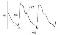
本発明の血圧測定装置で測定した吻合部内圧の圧波形(事実上、動脈波形に等しい)を解析して、心拍出量を求める方法を以下に記載する。まず、吻合部内圧の圧波形の収縮期開始点を時間t=0とする。吻合部内圧の圧波形上で、時間tにおける動脈血液量をV(t)、1回心拍出量(ストロークボリューム)をSV(t)、毛細血管へ流出する血流量をQ(t)とすると、収縮期(大動脈弁が開いている間であって、図7に示す圧波形上のノッチより前の相)においては、以下の式(1)が成り立つ。 A method for determining the cardiac output by analyzing the pressure waveform (substantially equal to the arterial waveform) of the intra-anastomotic pressure measured by the blood pressure measuring device of the present invention is described below. First, the systolic start point of the pressure waveform of the anastomotic site internal pressure is set to time t = 0. On the pressure waveform of the systolic pressure, the arterial blood volume at time t is V (t), the cardiac output (stroke volume) is SV (t), and the blood flow to the capillaries is Q (t). Then, in the systole (while the aortic valve is open and before the notch on the pressure waveform shown in FIG. 7), the following equation (1) holds.

一方、毛細血管へ流出する血液量Q(t)は血圧P(t)に比例し、総末梢循環抵抗値Rに反比例すると仮定すると、式(2)が成り立つ。 On the other hand, assuming that the amount of blood Q (t) flowing out to the capillaries is proportional to the blood pressure P (t) and inversely proportional to the total peripheral circulatory resistance value R, the equation (2) holds.
式(2)を式(1)に代入すると、式(3)となる。 Substituting equation (2) into equation (1) yields equation (3).
さらに、動脈血液量V(t)は血圧P(t)に比例すると仮定すると、式(4)が得られる。
V(t)=α×P(t)+Vconst ・・・ (4)
式(4)の両辺をtで微分すると、式(5)となる。Further, assuming that the arterial blood volume V (t) is proportional to the blood pressure P (t), the equation (4) is obtained.
V (t) = α × P (t) + Vconst ... (4)
When both sides of the equation (4) are differentiated by t, the equation (5) is obtained.
式(5)を式(3)に代入すると、式(6)となる。 Substituting equation (5) into equation (3) yields equation (6).
式(6)を書き換えると式(7)となる。 When equation (6) is rewritten, it becomes equation (7).
従って、1回拍出量SVは、式(8)のように表すことができる。但し、t1は図7においてノッチが生じた時、すなわち大動脈弁が閉じた時である。 Therefore, the stroke amount SV can be expressed as in the equation (8). However, t1 is when the notch occurs in FIG. 7, that is, when the aortic valve is closed.
一方、大動脈弁が閉じた後、すなわちノッチの後については、SV(t)=0なので、式(1)は、式(9)のように書き換えることができる。 On the other hand, after the aortic valve is closed, that is, after the notch, since SV (t) = 0, the equation (1) can be rewritten as the equation (9).
毛細血管へ流出する血液量Q(t)が血圧P(t)に比例し、総末梢循環抵抗値Rに反比例すると仮定すると、式(10)のように表すことができる。 Assuming that the amount of blood Q (t) flowing out to the capillaries is proportional to the blood pressure P (t) and inversely proportional to the total peripheral circulatory resistance value R, it can be expressed by the equation (10).
式(10)を式(9)に代入すると、式(11)となる。 Substituting equation (10) into equation (9) yields equation (11).
さらに、大動脈弁が閉じた後であっても、動脈血液量V(t)は血圧P(t)に比例すると考えられる。すなわち、式(5)は、大動脈弁が閉じた後であっても成り立つ。そこで、式(5)を式(11)に代入すると式(12)が得られる。 Furthermore, even after the aortic valve is closed, the arterial blood volume V (t) is considered to be proportional to the blood pressure P (t). That is, equation (5) holds even after the aortic valve is closed. Therefore, by substituting the equation (5) into the equation (11), the equation (12) is obtained.
式(12)の両辺をt1からt2間で積分すると、式(13)となる。 When both sides of the equation (12) are integrated between t1 and t2, the equation (13) is obtained.
式(13)をさらに書き換えると、式(14)が得られる。 Further rewriting the equation (13) gives the equation (14).
式(14)を式(8)に代入すると、式(15)が得られる。 Substituting equation (14) into equation (8) gives equation (15).
一方、式(15)に基づいて、透析前の一回拍出量SV0は、式(16)のように表すことができる。On the other hand, based on the formula (15), the stroke volume SV0 before dialysis can be expressed as the formula (16).
ここで、式(15)と式(16)からSV/SV0を算出する式(17)を導くことができる。Here, the equation (17) for calculating SV / SV0 can be derived from the equations (15) and (16).
式(17)を書き換えると、SVの初期値SV0から任意の時点のSVを求める式(18)が得られる。By rewriting the equation (17), the equation (18) for obtaining the SV at an arbitrary time point can be obtained from the initial value SV0 of the SV.
ここで、血液透析開始時のSV0を与える方法を説明する。まず、心拍出量CO(L/分)は、以下の式(19)により心係数から求めることができる。Here, a method of giving SV0 at the start of hemodialysis will be described. First, the cardiac output CO (L / min) can be obtained from the cardiac index by the following equation (19).
CO=CI×BSA ・・・ (19)
ここでBSAは、患者の体表面積(m2)であり、以下に式(20)として示す藤本式により求めることができる。CO = CI x BSA ... (19)
Here, BSA is the body surface area (m2 ) of the patient and can be obtained by the Fujimoto formula shown below as formula (20).
BSA=[88.83×HT0.663×BW0.444]/10000 ・・・ (20)
HTは身長(cm)であり、BWは体重(kg)であり、CIは心係数である。患者の心係数CIの値は、正常人の心係数4.0L/min/m2と等しいと考えて差し支えない。これは、患者にたとえ心不全があっても、体内の水分量を増やし、交感神経系の緊張度を増して心係数を正常値に保つっているからである。そこで、患者の心拍出量は以下の式(21)で求められる。BSA = [88.83 x HT0.663 x BW0.444 ] / 10000 ... (20)
HT is height (cm), BW is body weight (kg), and CI is cardiac index. It can be considered that the value of the cardiac index CI of the patient is equal to the cardiac index of 4.0 L / min / m2 of a normal person. This is because even if the patient has heart failure, it increases the amount of water in the body, increases the tension of the sympathetic nervous system, and keeps the cardiac index at a normal value. Therefore, the cardiac output of the patient is calculated by the following formula (21).
CO=4×BSA ・・・ (21)
心拍数をHRとすると、一回拍出量SV0(ml)は、以下の式(22)のように表すことができる。CO = 4 × BSA ・ ・ ・ (21)
Assuming that the heart rate is HR, the stroke volume SV0 (ml) can be expressed by the following equation (22).
SV0=1000×CO/HR ・・・ (22)
これに式(19)及び式(20)を代入すると式(23)が得られる。SV0 = 1000 x CO / HR ... (22)
By substituting Eqs. (19) and (20) into this, Eq. (23) is obtained.
SV0=4000×[88.83×HT0.663×BW0.444]/10000/HR ・・・ (23)
ここで、1回の心拍にかかる秒数をT2(sec)とすると、心拍数HRは、HR=60/T2と表すことができる。これを式(22)に代入すると、SVは1000×CO/(60/T2)となる。また、SV0は、1000×CO0/(60/T20)となる。これを式(18)に代入すると式(24)が得られる。SV0 = 4000 x [88.83 x HT0.663 x BW0.444 ] / 10000 / HR ... (23)
Here, assuming that the number of seconds required for one heartbeat is T2 (sec), the heart rate HR can be expressed as HR = 60 / T2. Substituting this into equation (22), SV becomes 1000 × CO / (60 / T2). Moreover, SV0 becomes1000 × CO 0 / (60 / T2 0). Substituting this into equation (18) gives equation (24).
式(24)を書き換えると、任意の時点の心拍出量を算出する式(25)が導かれる。By rewriting the equation (24), the equation (25) for calculating the cardiac output at an arbitrary time point is derived.
また、透析中の任意の時点における末梢循環抵抗SVR(mmHg/L/min)は、平均血圧MBP及び心拍出量COから以下の式(26)により求めることができる。 In addition, the peripheral circulatory resistance SVR (mmHg / L / min) at any time during dialysis can be calculated from the average blood pressure MBP and cardiac output CO by the following formula (26).
平均血圧MBPは、式(27)から求めることができる。 The average blood pressure MBP can be calculated from the formula (27).
図1において、シャント血管が患者の前腕部に形成されており、前腕部において血圧を測定する例を示した。しかし、上腕部又は下肢等にシャント血管が形成されている場合、これらの部位において同様に血圧を測定することができる。 FIG. 1 shows an example in which a shunt blood vessel is formed in a patient's forearm and blood pressure is measured in the forearm. However, when shunt blood vessels are formed in the upper arm or lower limb, blood pressure can be measured in the same manner at these sites.
なお、心拍出量を求める際の血液透析開始時の一回心拍出量(ストロークボリューム)は、心係数の標準値から算出した。しかし、血液透析開始時の一回心拍出量(ストロークボリューム)に胸部超音波検査で測定された個々の患者の値を用いてもよい。 The single cardiac output (stroke volume) at the start of hemodialysis when determining the cardiac output was calculated from the standard value of the cardiac index. However, individual patient values measured by chest ultrasonography may be used for the stroke volume at the start of hemodialysis.
本開示の血圧測定装置は、連続して正確な血圧測定ができ、治療又は処置の際の血圧測定において有用である。 The blood pressure measuring device of the present disclosure can continuously and accurately measure blood pressure, and is useful in blood pressure measurement during treatment or treatment.
110 歪センサ
111 歪センサ本体
112 ケース
113 開口部
114 上部
115 下部
120 バンド
121 本体部
122 幅広部
123 保持部材
130 制御回路
132 駆動部
133 処理部
150 圧測定部
151 プラスチックカバー
152 ゲル状液袋
201 シャント血管110 Strain sensor 111 Strain sensor body 112 Case 113 Opening 114 Upper 115
Claims (9)
Translated fromJapanese前記圧測定部をシャント血管の吻合部を覆う皮膚の上に静止させて固定する固定具と、
前記圧測定部からの信号が入力され、入力された信号を処理してシャント血管の吻合部内の圧を算出する制御回路とを備え、
前記固定具が、前記圧測定部と該圧測定部とは反対側の皮膚表面との距離を、常に一定に保つ、血圧測定装置。Pressure measuring unit and
A fixture that holds the pressure measuring part stationary on the skin covering the anastomotic part of the shunt blood vessel, and
It is provided with a control circuit in which a signal from the pressure measuring unit is input and the input signal is processed to calculate the pressure in the anastomotic portion of the shunt blood vessel.
A blood pressure measuring device in which the fixture always keeps a constant distance between the pressure measuring unit and the skin surface on the side opposite to the pressure measuring unit.
Applications Claiming Priority (3)
| Application Number | Priority Date | Filing Date | Title |
|---|---|---|---|
| JP2015079527 | 2015-04-08 | ||
| JP2015079527 | 2015-04-08 | ||
| PCT/JP2016/001697WO2016163093A1 (en) | 2015-04-08 | 2016-03-23 | Blood pressure measuring device |
Publications (2)
| Publication Number | Publication Date |
|---|---|
| JPWO2016163093A1 JPWO2016163093A1 (en) | 2018-02-01 |
| JP6773028B2true JP6773028B2 (en) | 2020-10-21 |
Family
ID=57071886
Family Applications (1)
| Application Number | Title | Priority Date | Filing Date |
|---|---|---|---|
| JP2017511467AActiveJP6773028B2 (en) | 2015-04-08 | 2016-03-23 | Blood pressure measuring device |
Country Status (5)
| Country | Link |
|---|---|
| US (1) | US11241160B2 (en) |
| EP (1) | EP3269299B1 (en) |
| JP (1) | JP6773028B2 (en) |
| CN (1) | CN107708534B (en) |
| WO (1) | WO2016163093A1 (en) |
Families Citing this family (2)
| Publication number | Priority date | Publication date | Assignee | Title |
|---|---|---|---|---|
| US11730487B2 (en)* | 2019-08-29 | 2023-08-22 | Mohammad Reza Rajebi | Vascular hemostasis system |
| GB2625368A (en)* | 2022-12-16 | 2024-06-19 | M G Electric Colchester Ltd | Monitoring device |
Family Cites Families (29)
| Publication number | Priority date | Publication date | Assignee | Title |
|---|---|---|---|---|
| US3124132A (en)* | 1964-03-10 | Dynamic fluid pressure transducer | ||
| JPS59181129A (en)* | 1983-03-31 | 1984-10-15 | 株式会社エー・アンド・ディ | Hemomanometer |
| US4993422A (en)* | 1986-05-02 | 1991-02-19 | The Hon Group | Apparatus for measuring blood pressure |
| US5351694A (en)* | 1992-11-16 | 1994-10-04 | Protocol Systems, Inc. | Noninvasive-blood-pressure (NIBP) monitoring apparatus with noninflatable, pressure-information-providing (PIP) structure |
| US5617867A (en)* | 1994-11-23 | 1997-04-08 | Ivac Medical Systems, Inc. | Tonometer mounting device |
| JPH09294730A (en)* | 1996-05-02 | 1997-11-18 | Hagiwara Denki Kk | Vibration detection sensor at shunt formation site |
| US5848970A (en)* | 1996-12-13 | 1998-12-15 | Vitalwave Corp. | Apparatus and method for non-invasively monitoring a subject's arterial blood pressure |
| JP3858379B2 (en)* | 1997-10-08 | 2006-12-13 | セイコーエプソン株式会社 | Cardiac output detection device and cardiac function diagnosis device |
| GB9714550D0 (en)* | 1997-07-10 | 1997-09-17 | Lidco Ltd | Improved method and apparatus for the measurement of cardiac output |
| US6176831B1 (en)* | 1998-07-20 | 2001-01-23 | Tensys Medical, Inc. | Apparatus and method for non-invasively monitoring a subject's arterial blood pressure |
| CN1163191C (en)* | 1999-04-21 | 2004-08-25 | 陆渭明 | Wound-less continuous blood pressure measuring method and device |
| JP2001087231A (en)* | 1999-09-20 | 2001-04-03 | Matsushita Electric Ind Co Ltd | Sphygmomanometer |
| JP2002172095A (en)* | 2000-12-06 | 2002-06-18 | K & S:Kk | Pulse measurement device |
| JP2002224064A (en) | 2001-02-02 | 2002-08-13 | Omron Corp | Pressure pulse wave sensor |
| US6730038B2 (en)* | 2002-02-05 | 2004-05-04 | Tensys Medical, Inc. | Method and apparatus for non-invasively measuring hemodynamic parameters using parametrics |
| JP2003333152A (en)* | 2002-03-05 | 2003-11-21 | Seiko Instruments Inc | Wearable electronic device |
| US20040073123A1 (en)* | 2002-10-11 | 2004-04-15 | Hessel Stephen R. | Apparatus and methods for non-invasively measuring hemodynamic parameters |
| WO2004069049A1 (en) | 2003-02-10 | 2004-08-19 | Sumio Sugahara | Blood pressure pulsation measuring device and mounting implement for measuring blood pressure and pulse wave |
| JP4306381B2 (en)* | 2003-09-17 | 2009-07-29 | オムロンヘルスケア株式会社 | Wrist fixing device for pulse wave measuring device and pulse wave measuring device |
| JP2008012230A (en)* | 2006-07-10 | 2008-01-24 | Omron Healthcare Co Ltd | Pulse wave output device and program |
| US8370549B2 (en)* | 2007-09-07 | 2013-02-05 | Nike, Inc. | Wearable device assembly having athletic functionality |
| JP5176880B2 (en)* | 2008-11-04 | 2013-04-03 | オムロンヘルスケア株式会社 | Blood pressure information measuring device |
| JP5401678B2 (en)* | 2009-02-09 | 2014-01-29 | 株式会社イデアルスター | Dialysis patient probe gauze and dialysis patient judgment device |
| JP5514990B2 (en)* | 2009-11-06 | 2014-06-04 | 株式会社イデアルスター | Shunt sound monitoring system |
| JP2012152372A (en)* | 2011-01-26 | 2012-08-16 | Omron Healthcare Co Ltd | Blood pressure measurement device and blood pressure measurement method |
| US9655530B2 (en) | 2011-04-29 | 2017-05-23 | Tensys Medical, Inc. | Apparatus and methods for non-invasively measuring physiologic parameters of one or more subjects |
| DE102011114666A1 (en) | 2011-09-30 | 2013-04-04 | Pulsion Medical Systems Se | Device for hemodynamic monitoring |
| CN104703552B (en)* | 2012-08-13 | 2018-03-30 | 莫尔研究应用有限公司 | radial artery device |
| WO2015126095A1 (en)* | 2014-02-21 | 2015-08-27 | 삼성전자 주식회사 | Electronic device |
- 2016
- 2016-03-23WOPCT/JP2016/001697patent/WO2016163093A1/ennot_activeCeased
- 2016-03-23USUS15/564,527patent/US11241160B2/enactiveActive
- 2016-03-23EPEP16776271.5Apatent/EP3269299B1/enactiveActive
- 2016-03-23JPJP2017511467Apatent/JP6773028B2/enactiveActive
- 2016-03-23CNCN201680020016.6Apatent/CN107708534B/enactiveActive
Also Published As
| Publication number | Publication date |
|---|---|
| EP3269299B1 (en) | 2019-05-22 |
| CN107708534B (en) | 2021-04-30 |
| JPWO2016163093A1 (en) | 2018-02-01 |
| US20180070838A1 (en) | 2018-03-15 |
| EP3269299A4 (en) | 2018-03-28 |
| EP3269299A1 (en) | 2018-01-17 |
| CN107708534A (en) | 2018-02-16 |
| US11241160B2 (en) | 2022-02-08 |
| WO2016163093A1 (en) | 2016-10-13 |
Similar Documents
| Publication | Publication Date | Title |
|---|---|---|
| US8211031B2 (en) | Non-invasive intracranial monitor | |
| US20100106016A1 (en) | Non-Invasive Blood Pressure Monitoring Device and Method | |
| US20170258344A1 (en) | Device and method for measurement of intracranial pressure | |
| US20190200879A1 (en) | Non-invasive system and method for measuring blood pressure variability | |
| JP2017510411A (en) | Method for determining blood pressure in a blood vessel and apparatus for performing the method | |
| US20160213332A1 (en) | Measuring apparatus and measuring method | |
| WO2013061765A1 (en) | Measuring device, evaluation method, and evaluation program | |
| JP6773028B2 (en) | Blood pressure measuring device | |
| JP5976558B2 (en) | Biological monitoring device and program | |
| EP3430983B1 (en) | Blood pressure/pulse wave measurement device | |
| US11219378B2 (en) | Method and device for continuous blood pressure monitoring and estimation | |
| CN113543701A (en) | Blood pressure measurement system and blood pressure measurement method using same | |
| WO2013061766A1 (en) | Measuring device, index calculation method, and index calculation program | |
| JP2008307307A (en) | Evaluation method and apparatus for vascular function | |
| Lacković | Inspection and testing of noninvasive blood pressure measuring devices | |
| EP3581104A1 (en) | Method, device and computer program product for estimating a compliance of a blood vessel in a subject | |
| Dubey | Non Invasive Blood Pressure Measurement Techniques: A Survey | |
| Sorvoja et al. | Systolic blood pressure accuracy enhancement in the electronic palpation method using pulse waveform | |
| CN116803339A (en) | Device and method for triggering blood pressure measurement |
Legal Events
| Date | Code | Title | Description |
|---|---|---|---|
| A621 | Written request for application examination | Free format text:JAPANESE INTERMEDIATE CODE: A621 Effective date:20181211 | |
| A131 | Notification of reasons for refusal | Free format text:JAPANESE INTERMEDIATE CODE: A131 Effective date:20191203 | |
| A521 | Request for written amendment filed | Free format text:JAPANESE INTERMEDIATE CODE: A523 Effective date:20200203 | |
| A131 | Notification of reasons for refusal | Free format text:JAPANESE INTERMEDIATE CODE: A131 Effective date:20200317 | |
| A521 | Request for written amendment filed | Free format text:JAPANESE INTERMEDIATE CODE: A523 Effective date:20200508 | |
| TRDD | Decision of grant or rejection written | ||
| A01 | Written decision to grant a patent or to grant a registration (utility model) | Free format text:JAPANESE INTERMEDIATE CODE: A01 Effective date:20200901 | |
| A61 | First payment of annual fees (during grant procedure) | Free format text:JAPANESE INTERMEDIATE CODE: A61 Effective date:20200914 | |
| R150 | Certificate of patent or registration of utility model | Ref document number:6773028 Country of ref document:JP Free format text:JAPANESE INTERMEDIATE CODE: R150 | |
| R250 | Receipt of annual fees | Free format text:JAPANESE INTERMEDIATE CODE: R250 |