JP6773024B2 - Recording device, recording method and computer program - Google Patents
Recording device, recording method and computer programDownload PDFInfo
- Publication number
- JP6773024B2 JP6773024B2JP2017504973AJP2017504973AJP6773024B2JP 6773024 B2JP6773024 B2JP 6773024B2JP 2017504973 AJP2017504973 AJP 2017504973AJP 2017504973 AJP2017504973 AJP 2017504973AJP 6773024 B2JP6773024 B2JP 6773024B2
- Authority
- JP
- Japan
- Prior art keywords
- data
- recording
- unit
- vehicle
- mobile terminal
- Prior art date
- Legal status (The legal status is an assumption and is not a legal conclusion. Google has not performed a legal analysis and makes no representation as to the accuracy of the status listed.)
- Active
Links
Images


Classifications
- G—PHYSICS
- G07—CHECKING-DEVICES
- G07C—TIME OR ATTENDANCE REGISTERS; REGISTERING OR INDICATING THE WORKING OF MACHINES; GENERATING RANDOM NUMBERS; VOTING OR LOTTERY APPARATUS; ARRANGEMENTS, SYSTEMS OR APPARATUS FOR CHECKING NOT PROVIDED FOR ELSEWHERE
- G07C5/00—Registering or indicating the working of vehicles
- G07C5/08—Registering or indicating performance data other than driving, working, idle, or waiting time, with or without registering driving, working, idle or waiting time
- G07C5/0841—Registering performance data
- G07C5/085—Registering performance data using electronic data carriers
- G07C5/0858—Registering performance data using electronic data carriers wherein the data carrier is removable
- G—PHYSICS
- G06—COMPUTING OR CALCULATING; COUNTING
- G06Q—INFORMATION AND COMMUNICATION TECHNOLOGY [ICT] SPECIALLY ADAPTED FOR ADMINISTRATIVE, COMMERCIAL, FINANCIAL, MANAGERIAL OR SUPERVISORY PURPOSES; SYSTEMS OR METHODS SPECIALLY ADAPTED FOR ADMINISTRATIVE, COMMERCIAL, FINANCIAL, MANAGERIAL OR SUPERVISORY PURPOSES, NOT OTHERWISE PROVIDED FOR
- G06Q40/00—Finance; Insurance; Tax strategies; Processing of corporate or income taxes
- G06Q40/08—Insurance
- G—PHYSICS
- G07—CHECKING-DEVICES
- G07C—TIME OR ATTENDANCE REGISTERS; REGISTERING OR INDICATING THE WORKING OF MACHINES; GENERATING RANDOM NUMBERS; VOTING OR LOTTERY APPARATUS; ARRANGEMENTS, SYSTEMS OR APPARATUS FOR CHECKING NOT PROVIDED FOR ELSEWHERE
- G07C5/00—Registering or indicating the working of vehicles
- G07C5/008—Registering or indicating the working of vehicles communicating information to a remotely located station
- G—PHYSICS
- G08—SIGNALLING
- G08G—TRAFFIC CONTROL SYSTEMS
- G08G1/00—Traffic control systems for road vehicles
- G08G1/01—Detecting movement of traffic to be counted or controlled
- G08G1/0104—Measuring and analyzing of parameters relative to traffic conditions
- G08G1/0108—Measuring and analyzing of parameters relative to traffic conditions based on the source of data
- G08G1/0112—Measuring and analyzing of parameters relative to traffic conditions based on the source of data from the vehicle, e.g. floating car data [FCD]
- G—PHYSICS
- G08—SIGNALLING
- G08G—TRAFFIC CONTROL SYSTEMS
- G08G1/00—Traffic control systems for road vehicles
- G08G1/01—Detecting movement of traffic to be counted or controlled
- G08G1/0104—Measuring and analyzing of parameters relative to traffic conditions
- G08G1/0125—Traffic data processing
- G08G1/0129—Traffic data processing for creating historical data or processing based on historical data
- G—PHYSICS
- G08—SIGNALLING
- G08G—TRAFFIC CONTROL SYSTEMS
- G08G1/00—Traffic control systems for road vehicles
- G08G1/20—Monitoring the location of vehicles belonging to a group, e.g. fleet of vehicles, countable or determined number of vehicles
- G08G1/205—Indicating the location of the monitored vehicles as destination, e.g. accidents, stolen, rental
Landscapes
- Physics & Mathematics (AREA)
- General Physics & Mathematics (AREA)
- Business, Economics & Management (AREA)
- Accounting & Taxation (AREA)
- Finance (AREA)
- Engineering & Computer Science (AREA)
- Chemical & Material Sciences (AREA)
- Analytical Chemistry (AREA)
- Development Economics (AREA)
- Economics (AREA)
- Marketing (AREA)
- Strategic Management (AREA)
- Technology Law (AREA)
- General Business, Economics & Management (AREA)
- Theoretical Computer Science (AREA)
- Traffic Control Systems (AREA)
- Telephonic Communication Services (AREA)
- Time Recorders, Dirve Recorders, Access Control (AREA)
- Navigation (AREA)
Description
Translated fromJapanese本開示は、記録装置、記録方法及びコンピュータプログラムに関する。 The present disclosure relates to recording devices, recording methods and computer programs.
自動車等の移動体を運転する運転者の運転内容に応じて、自動車保険の保険料を割り引いたり、保険料の一部を運転者に還元したりするサービスがある。そのようなサービスを提供する保険会社は、自動車の挙動を取得するための機器を運転者に送付して自動車に設置してもらう。そして保険会社は、保険の更新時期などの所定のタイミングで、その機器を運転者から返却してもらうことで、運転者の運転内容をチェックすることができる。 There is a service that discounts the insurance premium of automobile insurance or returns a part of the insurance premium to the driver according to the driving content of the driver who drives a moving body such as a car. The insurance company that provides such a service sends the driver a device to capture the behavior of the vehicle for installation in the vehicle. Then, the insurance company can check the driving contents of the driver by having the driver return the device at a predetermined timing such as the insurance renewal time.
しかし、自動車の挙動を取得するための機器を製造したり、機器を送付したりすることは保険会社にとってコストと手間が掛かる。また保険会社への機器の返却も、運転者によっては手間がかかる。 However, it is costly and time-consuming for insurance companies to manufacture and send equipment for acquiring the behavior of automobiles. Also, returning the equipment to the insurance company may be troublesome for some drivers.
そこで、本開示では、移動体の挙動に関する高精度の情報を簡易な構成で取得することが可能な、新規かつ改良された記録装置、記録方法及びコンピュータプログラムを提案する。 Therefore, the present disclosure proposes a new and improved recording device, recording method, and computer program capable of acquiring highly accurate information on the behavior of a moving object with a simple configuration.
本開示によれば、センシングによるデータを出力するセンシング部と、移動体からの記録指示に応じて前記センシング部が出力する前記移動体の挙動に関するデータの記録を開始し、前記移動体からの記録指示の途絶に応じて前記センシング部が出力する前記移動体の挙動に関するデータの記録を終了する記録部と、前記記録部が記録したデータを外部の装置に送信する送信部と、を備える、記録装置が提供される。 According to the present disclosure, a sensing unit that outputs data by sensing and a data relating to the behavior of the moving body output by the sensing unit in response to a recording instruction from the moving body are started to be recorded, and recording from the moving body is started. A recording unit including a recording unit that ends recording of data relating to the behavior of the moving object output by the sensing unit in response to interruption of instructions, and a transmission unit that transmits the data recorded by the recording unit to an external device. Equipment is provided.
また本開示によれば、センシングを行うことと、前記センシングにより得られる、移動体の挙動に関するデータを記録することと、記録された前記データを外部の装置に送信することと、前記移動体に備えられた信号発信装置からの無線信号に応じて前記センシングにより得られるデータの記録開始および記録停止を制御することと、を含む、記録方法が提供される。 Further, according to the present disclosure, sensing is performed, data on the behavior of the moving body obtained by the sensing is recorded, the recorded data is transmitted to an external device, and the moving body is subjected to sensing. A recording method is provided, which includes controlling recording start and recording stop of data obtained by the sensing according to a radio signal from a signal transmitting device provided.
また本開示によれば、コンピュータに、センシングを行うことと、前記センシングにより得られる、移動体の挙動に関するデータを記録することと、記録された前記データを外部の装置に送信することと、前記移動体に備えられた信号発信装置からの無線信号に応じて前記センシングにより得られるデータの記録開始および記録停止を制御することと、を実行させる、コンピュータプログラムが提供される。 Further, according to the present disclosure, sensing is performed on a computer, data on the behavior of a moving object obtained by the sensing is recorded, and the recorded data is transmitted to an external device. A computer program is provided that controls recording start and recording stop of data obtained by the sensing according to a radio signal from a signal transmitting device provided in the moving body, and executes the recording.
以上説明したように本開示によれば、移動体の挙動に関する高精度の情報を簡易な構成で取得することが可能な、新規かつ改良された記録装置、記録方法及びコンピュータプログラムを提供することが出来る。 As described above, according to the present disclosure, it is possible to provide a new and improved recording device, recording method and computer program capable of acquiring highly accurate information on the behavior of a moving object with a simple configuration. You can.
なお、上記の効果は必ずしも限定的なものではなく、上記の効果とともに、または上記の効果に代えて、本明細書に示されたいずれかの効果、または本明細書から把握され得る他の効果が奏されてもよい。 It should be noted that the above effects are not necessarily limited, and together with or in place of the above effects, any of the effects shown herein, or any other effect that can be grasped from this specification. May be played.
以下に添付図面を参照しながら、本開示の好適な実施の形態について詳細に説明する。なお、本明細書及び図面において、実質的に同一の機能構成を有する構成要素については、同一の符号を付することにより重複説明を省略する。 Preferred embodiments of the present disclosure will be described in detail below with reference to the accompanying drawings. In the present specification and the drawings, components having substantially the same functional configuration are designated by the same reference numerals, so that duplicate description will be omitted.
なお、説明は以下の順序で行うものとする。
1.第1の実施の形態
1.1.システム構成例
1.2.機能構成例
1.3.動作例
1.4.変形例
2.第2の実施の形態
3.まとめThe explanations will be given in the following order.
1. 1. First Embodiment 1.1. System configuration example 1.2. Functional configuration example 1.3. Operation example 1.4. Modification example 2.
<1.第1の実施形態>
[1.1.システム構成例]
まず、本開示の第1の実施形態に係るシステムの構成例について説明する。<1. First Embodiment>
[1.1. System configuration example]
First, a configuration example of the system according to the first embodiment of the present disclosure will be described.
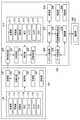
図1は、本開示の第1の実施形態に係るシステムの構成例を示す説明図である。図1に示したのは、スマートフォンなどのセンサを内蔵した携帯端末で、自動車の挙動をセンシングして、センシングの結果をサーバに送信するシステムの概略構成である。以下、図1を用いて本開示の第1の実施形態に係るシステムの構成例について説明する。 FIG. 1 is an explanatory diagram showing a configuration example of a system according to the first embodiment of the present disclosure. FIG. 1 shows a schematic configuration of a system in which a mobile terminal having a built-in sensor such as a smartphone senses the behavior of an automobile and transmits the sensing result to a server. Hereinafter, a configuration example of the system according to the first embodiment of the present disclosure will be described with reference to FIG.
図1に示したのは、車両10の内部に、ビーコン信号を出力する信号出力装置100が備えられており、信号出力装置100が出力するビーコン信号を、同じく車両10の内部に位置し、センサを内蔵した携帯端末200が受信している様子である。携帯端末200は、センサとして、例えば加速度センサ、角速度センサ、地磁気センサ、気圧センサ、カメラ、マイク、位置センサ等を含みうる。携帯端末200は、ビーコン信号を受信し、車両10が走行を開始したと判断すると、センサによるセンシングを開始して、センシングにより生じたデータをサーバ300に送信する。サーバ300は、車両保険を提供する保険会社が管理するサーバである。 As shown in FIG. 1, a
すなわち車両10の内部に位置する携帯端末200は、センシングの開始によって、加速、減速、停止といった車両10の挙動をセンシングすることになる。 That is, the
そして、車両保険を提供する保険会社が管理するサーバ300は、携帯端末200がセンシングしたデータを受信することで、車両10の挙動の様子を把握することが可能になる。そして車両保険を提供する保険会社は、車両10の挙動の様子をサーバ300で取得することで、サーバ300から、車両10を所有する運転者に対して運転内容のフィードバックを行ったり、車両保険の割引やキャッシュバックを行ったりすることが可能となる。 Then, the
以上、図1を用いて本開示の第1の実施形態に係るシステムの構成例について説明した。続いて、本開示の第1の実施形態に係る信号出力装置100及び携帯端末200の機能構成例について説明する。 The configuration example of the system according to the first embodiment of the present disclosure has been described above with reference to FIG. Subsequently, a functional configuration example of the
[1.2.機能構成例]
図2は、本開示の第1の実施形態に係る信号出力装置100及び携帯端末200の機能構成例を示す説明図である。以下、図2を用いて本開示の第1の実施形態に係る信号出力装置100及び携帯端末200の機能構成例について説明する。[1.2. Function configuration example]
FIG. 2 is an explanatory diagram showing a functional configuration example of the
図2に示したように、本開示の第1の実施形態に係る信号出力装置100は、センサ部110と、記憶部120と、電源部130と、測定部140と、ID読出部150と、送信部160と、を含んで構成される。 As shown in FIG. 2, the
また図2に示したように、本開示の第1の実施形態に係る携帯端末200は、センサ部210と、信号受信部220と、ID判別部222と、測定部224と、状態判定部226と、イベント検出部228と、データ記録部230と、UI部232と、表示部234と、関連情報収集部236と、通信部238と、記憶部240と、制御部800と、を含んで構成される。 Further, as shown in FIG. 2, the
なお、図2には信号出力装置100と携帯端末200との両方がセンサ部を有する構成が示されているが、本開示は係る例に限定されるものでは無い。例えば、信号出力装置100はセンサ部110を有していなくても良い。 Although FIG. 2 shows a configuration in which both the
まず信号出力装置100の機能構成を詳細に説明する。センサ部110は、信号出力装置100の挙動や周囲の状況などをセンシングするセンサの集合体である。本実施形態では、センサ部110は、加速度センサ111、角速度センサ112、地磁気センサ113、気圧センサ114、マイク115、カメラ116、GPSモジュール117を含んで構成される。もちろん、センサ部110を構成するセンサは係る例に限定されるものでは無く、すなわちこれらのセンサが全て含まれていなくても良い。 First, the functional configuration of the
加速度センサ111は、加速度をセンシングするセンサである。角速度センサ112は、角速度をセンシングするセンサである。地磁気センサ113は、地磁気の方向や強さをセンシングするセンサである.気圧センサは、気圧の大きさをセンシングするセンサである。マイク115は、信号出力装置100の周囲の音を記録するデバイスである。カメラ116は、信号出力装置100の周囲を撮像するデバイスである。GPSモジュール117は、信号出力装置100の現在位置をセンシングするデバイスである。 The
記憶部120は、例えばフラッシュメモリなどの不揮発性メモリで構成され、信号出力装置100の動作のためのプログラムや種々の情報を記憶する。例えば、記憶部120は、車両10を一意に識別するためのIDを記憶する。なお記憶部120は不揮発性メモリであるため、電源部130からの電源供給が途絶えてもプログラムや種々の情報を記憶できる。 The
電源部130は、例えば一次電池や二次電池で構成され、信号出力装置100の各部に電力を供給する。 The
測定部140は、センサ部110を用いて信号出力装置100の挙動を測定する。具体的には、測定部140は、センサ部110からセンシングデータを取得する。測定部140が取得したセンシングデータは送信部160から送信される。 The measuring
ID読出部150は、記憶部120が記憶している、車両10を一意に識別するためのIDを読み出す。ID読出部150が読み出したIDは送信部160からビーコン信号に含まれて送信される。 The
送信部160は、所定の間隔、例えば10秒間隔でビーコン信号を出力する。送信部160は、例えばWi−FiやBluetooth(登録商標)などの無線、磁気、音声、光、振動などによってビーコン信号を出力する。送信部160は、ID読出部150が記憶部120から読み出したIDをビーコン信号に含めて出力する。また送信部160は、測定部140が取得したセンシングデータを出力してもよい。 The
続いて携帯端末200の機能構成を詳細に説明する。センサ部210は、携帯端末200の挙動や周囲の状況などをセンシングするセンサの集合体である。本実施形態では、センサ部210は、加速度センサ211、角速度センサ212、地磁気センサ213、気圧センサ214、マイク215、カメラ216、GPSモジュール217を含んで構成される。もちろん、センサ部110を構成するセンサは係る例に限定されるものでは無く、すなわちこれらのセンサが全て含まれていなくても良い。 Subsequently, the functional configuration of the
センサ部210は、携帯端末200の挙動をセンシングするのはもちろんのこと、携帯端末200が車両10の中に置かれている状態では車両10の挙動、すなわち加速、減速、停止等の状態もセンシングすることが出来る。 The
信号受信部220は、信号出力装置100が出力するビーコン信号を受信する。信号受信部220は、ビーコン信号を受信すると、そのビーコン信号の内容をID判別部222に送る。信号受信部220が受信したビーコン信号に含まれる内容には、例えば、信号出力装置100に記憶されている、車両10を一意に識別するためのIDが含まれる。 The
ID判別部222は、信号受信部220が受信したビーコン信号に含まれる、車両10を一意に識別するためのIDと、記憶部240に記憶されているIDとが一致するかどうかを判別する。すなわち、携帯端末200のユーザが乗車した車両が、保険会社等との契約で決められた車両であるかどうかをID判別部222が判別する。 The
ID判別部222は、信号受信部220が受信したビーコン信号に含まれる、車両10を一意に識別するためのIDと、記憶部240に記憶されているIDとが一致していれば、センサ部210によるセンシングに基づいた、測定部224による車両10の動作の測定を開始させる。 The
測定部224は、ID判別部222による判別結果に応じて、センサ部210を用いて携帯端末200の挙動を測定する。具体的には、測定部224は、センサ部210からセンシングデータを取得することで携帯端末200の挙動を測定する。センサ部210は、携帯端末200の挙動を常に測定している。一方、測定部224は、センサ部210から常時センシングデータを取得するのでは無く、ID判別部222による判別結果に応じてセンサ部210からセンシングデータを取得する。測定部224は、ID判別部222による判別結果に応じてセンサ部210からセンシングデータを取得することで、携帯端末200のユーザが乗車した車両が、保険会社等との契約で決められた車両である場合において、その車両の挙動を測定することができる。 The
状態判定部226は、測定部224による測定結果を用いて車両10の状態を判定する。携帯端末200が車両10の中にある場合、センサ部210によるセンシング結果は常に車両10の挙動を現しているとは限らない。車両10の運転手や同乗者が、車両10の走行中や停止中に携帯端末200を操作する場合があるからである。そのような場合を鑑みて、状態判定部226は、測定部224による測定結果から、例えば車両10の走行中の携帯端末200の操作の有無を判定する。例えば、状態判定部226は、測定部224による測定結果を用いて携帯端末200が静止しているかどうかの判定を行う。状態判定部226は、携帯端末200の静止を、例えば加速度センサ211、角速度センサ212、地磁気センサ213、気圧センサ214等のセンシングデータから判定しても良い。 The
状態判定部226は、例えば、GPSモジュール217による位置情報の測位から得られる速度と、加速度センサ211がセンシングした加速度の積分による速度とに差が有れば、携帯端末200が運転手や同乗者によって操作されたと判定しても良い。また、携帯端末200が信号出力装置100からセンシングデータを取得できる場合、状態判定部226は、信号出力装置100が出力するセンシングデータと、センサ部210が出力するセンシングデータとの差分から、車両10の状態を判定してもよい。 In the
状態判定部226は、測定部224による測定結果を用いて車両10の状態を判定する際に、車両10の走行中や停止中に携帯端末200が操作されていると判定した場合は、携帯端末200を操作しているのが運転者なのか同乗者なのかを判別しても良い。状態判定部226は、例えば、測定部224による測定結果から車両10の走行中に携帯端末200が操作されていると判定した場合は、携帯端末200を操作しているのは同乗者であると判定しても良い。そして状態判定部226は、携帯端末200を操作しているのが運転者なのか同乗者なのかを判別すると、判別の結果に応じて表示部234に表示させる内容を変化させても良い。 When the
イベント検出部228は、測定部224による測定結果を用いて特定のイベントが発生したかどうかを検出する。イベント検出部228は、測定部224による測定結果を用いて、特定のイベントとして例えば車両10の衝突などを検出する。イベント検出部228は、車両10の衝突を、例えば急激な速度の低下や衝撃などの発生によって検出することが出来る。 The
イベント検出部228は、特定のイベントを検出すると、その検出したイベントの内容に応じた表示を表示部234に表示させるよう、UI部232に指示する。例えばイベント検出部228は、測定部224による測定結果を用いて、特定のイベントとして車両10の衝突を検出すると、保険会社に緊急連絡するためのUIを表示部234に表示させるよう、UI部232に指示する。 When the
データ記録部230は、測定部224による測定結果を記憶部240に記録する。データ記録部230が記録した測定部224による測定結果は、所定のタイミングでサーバ300に送信される。データ記録部230は、センサ部210にて測定されたセンシングデータを測定された時間と共に記録してもよいし、センシングデータを状態判定部226にて解析することにより、走行している車両10の車速、加減速に関する情報、アクセルまたはブレーキの有無、走行方向、高度、衝撃の有無、蛇行運転の有無、3次元上の各軸における傾き情報等を記録してもよい。 The
データ記録部230は、測定部224による測定結果を記憶部240に常時記録してもよいが、所定の条件、すなわち、車両10が走行を開始すると考えられる条件を満たした場合に限り測定部224による測定結果を記憶部240に記録しても良い。例えば、データ記録部230は、信号受信部220が受信するビーコン信号に含まれるセンシングデータの変化の発生や、信号受信部220によるビーコンの受信に応じて測定結果の記録を開始しても良い。また例えば、データ記録部230は、携帯端末200が静止したことを検出すると測定結果の記録を開始しても良い。携帯端末200の静止は、例えば加速度センサ211、角速度センサ212、地磁気センサ213、気圧センサ214等のセンシングデータから検知しても良い。また例えば、データ記録部230は、ドアの開閉、走行、空調による気圧変化など、所定の気圧の変化を検出すると測定結果の記録を開始しても良い。また例えば、データ記録部230は、車両の起動音、エンジンの始動音、走行音、風切り音、ドアの開閉音等の所定の音の発生を検出すると測定結果の記録を開始しても良い。また例えば、データ記録部230は、自宅や会社などの特定の位置からの移動等の位置の変化を検出すると測定結果の記録を開始しても良い。また例えば、データ記録部230は、駐車場からの移動等の方位や速度の変化を検出すると測定結果の記録を開始しても良い。 The
またデータ記録部230は、所定の条件、すなわち、車両10の走行が終了すると考えられる条件を満たした場合に測定部224による測定結果の記録を停止しても良い。例えば、データ記録部230は、信号受信部220が受信するビーコン信号に含まれるセンシングデータが変化しなくなったことや、信号受信部220によるビーコンを受信しなくなったことに応じて測定結果の記録を停止しても良い。また例えば、データ記録部230は、携帯端末200が操作されたことを検出すると測定結果の記録を停止しても良い。また例えば、データ記録部230は、ドアの開閉、走行、空調による気圧変化など、所定の気圧の変化を検出すると測定結果の記録を停止しても良い。また例えば、データ記録部230は、車両の起動音、エンジンの始動音、走行音、風切り音、ドアの開閉音等の所定の音がしなくなったことを検出すると測定結果の記録を停止しても良い。また例えば、データ記録部230は、自宅や会社などの特定の位置に移動したことを検出すると測定結果の記録を停止しても良い。また例えば、データ記録部230は、駐車場への駐車等の方位や速度の変化を検出すると測定結果の記録を停止しても良い。 Further, the
UI部232は、表示部234に表示するユーザインタフェースを生成する。UI部232は、本開示の表示制御部の一例として機能しうる。例えば上述したように、イベント検出部228が車両10の衝突を検出すると、UI部232は、保険会社に緊急連絡するためのUIを表示部234に表示させるユーザインタフェースを生成する。 The
その他にもUI部232は様々なユーザインタフェースを生成する。詳細は後述するが、例えば、UI部232は、車両10の運転に関する情報、車両保険の更新に関する情報、車両10から降車した際にその降車位置の近隣の施設で使用できるクーポンの情報、車両10の駐車位置や駐車時間に関する情報などを表示部234に表示する。 In addition, the
表示部234は、種々の情報を表示するデバイスであり、例えば液晶ディスプレイや有機ELディスプレイなどで構成される。表示部234は、例えばUI部232が生成したユーザインタフェースを表示する。 The
関連情報収集部236は、携帯端末200に関連する情報を収集する。関連情報収集部236は、例えば、携帯端末200のユーザが車両10から降車した際に、携帯端末200の位置情報に基づき、その降車位置の近隣の施設で使用できるクーポンの情報を収集する。関連情報収集部236は、携帯端末200の位置情報に基づいて、携帯端末200に関連する情報を収集すると、収集した情報をUI部232に渡す。UI部232は、関連情報収集部236から渡された情報に基づいて、降車位置の近隣の施設で使用できるクーポンの情報を表示部234に表示させるためのユーザインタフェースを生成することが出来る。 The related
もちろん関連情報収集部236が収集する情報は係る例に限定されるものでは無い。 Of course, the information collected by the related
通信部238は、有線または無線によって外部と通信する通信モジュールである。本実施形態では、通信部238は、例えば、データ記録部230が記録した測定部224による測定結果をサーバ300に送信する。 The
記憶部240は、例えばフラッシュメモリなどの不揮発性メモリで構成され、携帯端末200の動作のためのプログラムや種々の情報を記憶する。例えば、記憶部240は、保険会社との契約によって定められたIDを記憶する。このIDは、信号出力装置100で記憶されているIDと、ID判別部222によって一致しているかどうかの判定がなされる。なお記憶部240は不揮発性メモリであるため、バッテリ(図示せず)などからの電源供給が途絶えてもプログラムや種々の情報を記憶できる。制御部800は、携帯端末200の動作全般を制御する。例えば、制御部800は、図3を参照して説明するように、表示部234の表示、およびデータ記録部230によるデータの記録などを制御する。 The
本開示の第1の実施形態に係る信号出力装置100及び携帯端末200は、係る構成を有することで、移動体である車両10の挙動に関する高精度の情報を取得することが可能となる。 The
以上、図2を用いて本開示の第1の実施形態に係る信号出力装置100及び携帯端末200の機能構成例について説明した。続いて、本開示の第1の実施形態に係る携帯端末200の動作例について説明する。 As described above, the functional configuration example of the
[1.3.動作例]
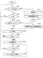
図3は、本開示の第1の実施形態に係る携帯端末200の動作例を示す流れ図である。図3に示したのは、センサ部210のセンシングにより車両10の挙動を記録する際の携帯端末200の動作例である。以下、図3を用いて本開示の第1の実施形態に係る携帯端末200の動作例について説明する。[1.3. Operation example]
FIG. 3 is a flow chart showing an operation example of the
携帯端末200は、信号出力装置100からのビーコン信号を受信したかどうかを判断する(ステップS101)。ステップS101の判断は、例えば信号受信部220が信号出力装置100からのビーコン信号を受信したかどうかを判断することにより行う。 The
携帯端末200は、信号出力装置100からのビーコン信号を受信した場合(ステップS101、Yes)、そのビーコン信号に含まれているIDと、携帯端末200が記憶部240で記憶しているIDとが一致しているかどうか判断する(ステップS102)。ステップS102の判断は、例えばID判別部222が行う。 When the
ステップS102の判断の結果、受信したビーコン信号に含まれているIDと、携帯端末200が記憶部240で記憶しているIDとが一致していなければ(ステップS102、No)、携帯端末200は、ステップS101のビーコン信号の受信判断処理に戻る。一方、ステップS102の判断の結果、受信したビーコン信号に含まれているIDと、携帯端末200が記憶部240で記憶しているIDとが一致していれば(ステップS102、Yes)、携帯端末200は、記憶部240に記憶している自動車保険の更新時期等を参照して特定のタイミングが来たかどうかを判断する(ステップS103)。ステップS103の判断は、例えばUI部232が行う。例えば、携帯端末200は、自動車保険の更新時期の特定のタイミングが来たかどうかを、記憶部240に記憶された自動車保険の更新時期やこれまでの走行距離に基づいて、例えば前回更新時から所定期間が経過したか、次回更新時期の所定期間前になったかどうか、あるいは、所定の距離を走行したかどうかで判断する。S102の結果、受信したビーコン信号に含まれているIDと、携帯端末200が記憶部240で記憶しているIDとが一致していなければ、制御部800は、携帯端末200の表示部に対して、IDが一致しない旨を表示するように制御してもよい。 As a result of the determination in step S102, if the ID included in the received beacon signal and the ID stored in the
ステップS103の判断の結果、特定のタイミングが来た場合は(ステップS103、Yes)、携帯端末200は、自動車保険の更新時期が近い旨の情報を表示部234に表示する(ステップS104)。ステップS104の処理は、例えばUI部232が行う。携帯端末200は、自動車保険の更新時期が近い旨の情報として、「自動車保険の更新時期が近づいています」等のメッセージと共に、オドメータの値の入力を促すメッセージとオドメータの撮像を促すメッセージを表示しても良い。 As a result of the determination in step S103, when a specific timing comes (step S103, Yes), the
続いて携帯端末200は、センサ部210による測定を実行する(ステップS105)。ステップS105の測定処理は例えば測定部224がセンサ部210より出力されたセンシングデータを取得することにより行う。 Subsequently, the
続いて携帯端末200は、ステップS105の測定結果により測定されたデータを用いて携帯端末20の状態を判定する(ステップS106)。ステップS106の判定処理は、例えば状態判定部226が行う。携帯端末200が車両10の中にある場合、センサ部210によるセンシング結果は常に車両10の挙動を現しているとは限らない。車両10の運転手や同乗者が、車両10の走行中や停止中に携帯端末200を操作する場合があるからである。そのような場合を鑑みて、携帯端末200は、ステップS105の測定結果を用いて、例えば車両10の走行中の携帯端末200の操作の有無を判定する。 Subsequently, the
ステップS106の判定の結果、携帯端末200が運転者や同乗者によって操作されていると判定した場合は、携帯端末200は、センサ部210による測定の実行に戻る。この場合、携帯端末200が運転者や同乗者によって操作されていると判定されている間は、後述S107の車両10の走行状態に関するデータの記録処理が行われないこととなる。一方、ステップS106の判定の結果、携帯端末200が運転者や同乗者によって操作されていない、すなわち、携帯端末200が車両10の中で静止していると判定した場合は、携帯端末200は、センサ部210より出力されたセンシングデータに基いた情報である、車両10の走行状態を記憶部240に記録する(ステップS107)。ステップS107の記録処理は、例えばデータ記録部230が実行する。S107において、データ記録部230は、制御部800の制御に基づいて、センサ部210にて測定されたセンシングデータを測定された時間と共に記録してもよいし、センシングデータを状態判定部226にて所定の演算を行うことにより識別された、走行している車両10の(1)車速、(2)加速または減速に関する情報、(3)アクセルまたはブレーキの有無、(4)走行方向、(5)高度、(6)車両10に対する衝撃の有無、(7)他の物体との衝突の有無、(8)蛇行運転の有無、(9)3次元上の各軸における傾き情報等を測定された時間と共に記録してもよい。例えば、上記(1)〜(9)のデータは、センサ部210に含まれる、加速度センサ、角速度センサより出力されるデータに基づいて判別される。上記ステップS106の判定の結果、携帯端末200が運転者や同乗者によって操作されていない、すなわち、携帯端末200が車両10の中で静止していると判定されたことに加えて、センサ部210より出力されたセンシングデータに基いて車両10が走行を開始したことを検知したことにより、ステップS107に移行して、車両10の走行状態を記憶部240に対する記録を開始してもよい。 As a result of the determination in step S106, when it is determined that the
携帯端末200は、上述したように、所定の条件を満たした場合に限り車両10の走行状態を記録しても良い。また携帯端末200は、上述したように、所定の条件を満たさなくなると、車両10の走行状態の記録を停止しても良い。 As described above, the
車両10の走行状態を記録している携帯端末200は、センサ部210より出力されたセンシングデータに基いて、記録中に所定のイベント、例えば車両10の衝突などが発生したかどうかを判断する(ステップS108)。ステップS108の判断処理は、例えばイベント検出部228が実行する。 The
所定のイベントが発生したと判断した場合は(ステップS108、Yes)、携帯端末200は、そのイベントに対応したユーザインタフェース、例えば、保険会社に緊急連絡するためのユーザインタフェースを表示部234に表示する(ステップS109)。表示部234に表示するユーザインタフェースは、例えばUI部232が生成する。一方、所定のイベントが発生していないと判断した場合は(ステップS108、No)、携帯端末200は、ステップS101のビーコン信号の受信判断処理に戻る。 When it is determined that a predetermined event has occurred (step S108, Yes), the
ステップS101のビーコン信号の受信判断処理において、信号出力装置100からのビーコン信号を受信していない場合(ステップS101、No)、携帯端末200は、車両10から離れたと判断して車両10の走行状態の記録を停止する(ステップS110)。そして携帯端末200は、現在位置の情報に基づき、現在位置の周辺の情報を検索して検索の結果に基づく情報を表示部234に表示する(ステップS111)。現在位置の周辺の情報の検索結果に基づく情報としては、例えば現在位置の近隣の施設で使用できるクーポンなどがある。また、ステップS101においては、ビーコン信号の受信判断処理に加えて、センサ部210より出力されたセンシングデータに基づいて、当該携帯端末を保持するユーザが車両10を降車したことを検出してもよい。この場合、例えば、信号出力装置100からのビーコン信号を受信していないことを検出し、かつ、携帯端末が静止状態ではない、あるいは、携帯端末が歩行するユーザに保持されている状態であることを検出して、ステップ110またはステップ111に移行してもよい。 In the beacon signal reception determination process of step S101, when the beacon signal from the
なお、ステップS102の判断の結果、受信したビーコン信号に含まれているIDと、携帯端末200が記憶部240で記憶しているIDとが一致していなければ、携帯端末200は、新たな自動車保険、例えば、1日限定での自動車保険の加入案内を表示部234に表示してもよい。 As a result of the determination in step S102, if the ID included in the received beacon signal and the ID stored in the
本開示の第1の実施形態に係る携帯端末200の一連の動作の例を、時間を軸とした図面を参照しながら説明する。図4は、本開示の第1の実施形態に係る携帯端末200の一連の動作の例を示す説明図である。 An example of a series of operations of the
図4の時刻t0からt1の区間では、携帯端末200は、センシングデータから時速4kmで移動していることが分かるが、信号出力装置100からのビーコン信号を受信していないので、車両10の中にいないと判断することが出来る。すなわち、時刻t1からt2の区間は、携帯端末200のユーザは歩行状態にあると携帯端末200は判断できる。 In the section from time t0 to t1 in FIG. 4, it can be seen from the sensing data that the
図4の時刻t1からt2の区間では、携帯端末200は、センシングデータから時速1kmで移動していることが分かる。そして携帯端末200は、信号出力装置100からのビーコン信号を受信し始めるので、車両10の中にいると判断することが出来る。 In the section from time t1 to t2 in FIG. 4, it can be seen from the sensing data that the
図4の時刻t2からt3の区間では、携帯端末200は、センシングデータから時速0kmであることが分かる。そして携帯端末200は、信号出力装置100からのビーコン信号を受信し始めるので、車両10の中にいると判断することが出来る。すなわち、携帯端末200は、図4の時刻t6からt7の区間では、車両10が停車している状態であると判断できる。また携帯端末200は、センシングデータからZ軸方向の加速度がほとんど変化していないので、車両10の中で静止している状態であると判断することが出来る。携帯端末200は、車両10の中で静止している状態であるので、センサ部210からのセンシングデータによる運転データの計測を開始する。 In the section from time t2 to t3 in FIG. 4, it can be seen from the sensing data that the
図4の時刻t3からt4の区間では、携帯端末200は、センシングデータから時速40kmで移動していることが分かる。そして携帯端末200は、信号出力装置100からのビーコン信号を受信し始めるので、車両10の中にいると判断することが出来る。すなわち、携帯端末200は、図4の時刻t3からt4の区間では、車両10が走行している状態であると判断できる。また携帯端末200は、センシングデータからZ軸方向の加速度がほとんど変化していないので、車両10の中で静止している状態であると判断することが出来る。携帯端末200は、車両10の中で静止している状態であるので、センサ部210からのセンシングデータによる運転データの計測を継続する。 In the section from time t3 to t4 in FIG. 4, it can be seen from the sensing data that the
図4の時刻t4からt5の区間では、携帯端末200は、センシングデータから時速40kmで移動していることが分かる。そして携帯端末200は、信号出力装置100からのビーコン信号を受信し始めるので、車両10の中にいると判断することが出来る。すなわち、携帯端末200は、図4の時刻t4からt5の区間では、車両10が停車している状態であると判断できる。しかし、携帯端末200は、センシングデータからZ軸方向の加速度が頻繁に変化しているので、車両10の中で静止していない状態であると判断することが出来る。携帯端末200は、車両10の中で静止していない状態であるので、運転者または同乗者によって操作されていると判断し、センサ部210からのセンシングデータによる運転データの計測を停止する。 In the section from time t4 to t5 in FIG. 4, it can be seen from the sensing data that the
図4の時刻t5からt6の区間では、携帯端末200は、センシングデータから時速60kmで移動していることが分かる。そして携帯端末200は、信号出力装置100からのビーコン信号を受信し始めるので、車両10の中にいると判断することが出来る。すなわち、携帯端末200は、図4の時刻t5からt6の区間では、車両10が走行している状態であると判断できる。また携帯端末200は、センシングデータからZ軸方向の加速度がほとんど変化していないので、車両10の中で静止している状態であると判断することが出来る。携帯端末200は、車両10の中で静止している状態であるので、センサ部210からのセンシングデータによる運転データの計測を再開する。 In the section from time t5 to t6 in FIG. 4, it can be seen from the sensing data that the
図4の時刻t6からt7の区間では、携帯端末200は、センシングデータから時速0kmであることが分かる。そして携帯端末200は、信号出力装置100からのビーコン信号を受信し始めるので、車両10の中にいると判断することが出来る。すなわち、携帯端末200は、図4の時刻t6からt7の区間では、車両10が停車している状態であると判断できる。また携帯端末200は、センシングデータからZ軸方向の加速度がほとんど変化していないので、車両10の中で静止している状態であると判断することが出来る。携帯端末200は、車両10の中で静止している状態であるので、センサ部210からのセンシングデータによる運転データの計測を継続する。 In the section from time t6 to t7 in FIG. 4, it can be seen from the sensing data that the
図4の時刻t7からt8の区間では、携帯端末200は、センシングデータから時速1kmで移動していることが分かる。そして携帯端末200は、信号出力装置100からのビーコン信号を受信しなくなるので、車両10の外にいると判断することが出来る。従って、携帯端末200は、センサ部210からのセンシングデータによる運転データの計測を停止する。そして携帯端末200は、図4の時刻t7からt8の区間において、時刻t2からt4まで、及び時刻t5からt7までの運転計測期間におけるセンシングデータから算出した運転スコアを表示部234に表示してもよい。 In the section from time t7 to t8 in FIG. 4, it can be seen from the sensing data that the
図4の時刻t8からt9の区間では、携帯端末200は、センシングデータから時速4kmで移動していることが分かるが、信号出力装置100からのビーコン信号を受信していないので、車両10の中にいないと判断することが出来る。すなわち、時刻t8からt9の区間は、携帯端末200のユーザは歩行状態にあると携帯端末200は判断できる。携帯端末200は、図4の時刻t8からt9の区間において、現在位置の近隣の施設で使用できるクーポンなどの関連情報を表示部234に表示してもよい。 In the section from time t8 to t9 in FIG. 4, it can be seen from the sensing data that the
続いて、本開示の第1の実施形態に係る携帯端末200の一連の動作の例を、積算走行距離を軸とした図面を参照しながら説明する。図5は、本開示の第1の実施形態に係る携帯端末200の一連の動作の例を示す説明図である。 Subsequently, an example of a series of operations of the
例えば、積算走行距離が10000kmの時点で、車両10の車両保険の契約者である携帯端末200のユーザがオドメータの値を所定のアプリに入力したとする。その後、当該ユーザが、携帯端末200を携帯したまま車両10を1000km運転する。その後、車両10の車両保険の契約者の家族が、携帯端末200を携帯したまま車両10を500km運転する。 For example, suppose that a user of a
その後、車両10の車両保険の契約者の家族が、車両10を500km運転するが、このときは携帯端末200を携帯するのを忘れていたとする。従って、実際の走行距離と、携帯端末200が測定する走行距離との間に500kmの差が生じる。 After that, it is assumed that the family of the vehicle insurance policyholder of the
その後、車両10の車両保険の契約者が、家族を同乗させて、携帯端末200を携帯したまま車両10を1500km運転する。そして、車両保険の更新時期が近づいてきたので、積算走行距離が13500kmの時点で、車両10の車両保険の契約者である携帯端末200のユーザがオドメータの値を所定のアプリに入力したとする。すると、実際の走行距離は3500kmであるが、携帯端末200が測定する走行距離は3000kmとなる。この3500km走行した期間での、携帯端末200を用いた測定の割合は距離比でおよそ86%である。この値が、例えば保険会社との契約でキャッシュバックを受けられる規定の範囲内であれば、車両10の車両保険の契約者は、保険会社からキャッシュバックを受けることが出来る。 After that, the vehicle insurance policyholder of the
携帯端末200で車両10の動作を測定する際に、契約者自身が運転する場合、契約者の家族が運転する場合、契約者に家族が同乗する場合、の3通りが考えられる。契約者自身が運転する場合は、携帯端末200に記憶されているIDが、信号出力装置100が出力するビーコン信号に含まれるIDと一致することになる。契約者の家族が運転する場合にも、その家族が携帯する携帯端末200に、予め、契約者が有する携帯端末200に記憶されているIDと同じIDを記憶させておくことで、契約車両を運転していることを携帯端末200が把握できる。また、契約者に家族が同乗する場合、すなわち、同じIDが記憶されている別々の携帯端末200が車両10の内部に存在する場合、同一のIDを有する別々の携帯端末200で収集された情報は、サーバ300で重複させないようにする。例えば、車両10を識別するIDとは別に携帯端末200のユーザを識別するIDを用意し、契約者のIDが格納されている携帯端末200が測定した車両10の動作のみがサーバ300で保持されるようにしてもよい。 When measuring the operation of the
続いて、携帯端末200が表示部234に表示するユーザインタフェースの例を示す。 Subsequently, an example of a user interface displayed on the
図6は、携帯端末200が表示部234に表示するユーザインタフェースの例を示す説明図である。図6は、例えば車両保険の更新時期等においてオドメータの値を入力させるためのユーザインタフェースの例である。 FIG. 6 is an explanatory diagram showing an example of a user interface displayed on the
図7は、携帯端末200が表示部234に表示するユーザインタフェースの例を示す説明図である。図7は、携帯端末200を持つユーザが車両10から降りた際に、その降車位置付近の施設で使用できるクーポンを自動的に表示するユーザインタフェースの例である。 FIG. 7 is an explanatory diagram showing an example of a user interface displayed on the
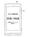
図8は、携帯端末200が表示部234に表示するユーザインタフェースの例を示す説明図である。図8は、携帯端末200を持つユーザが車両10を運転した際に、そのユーザによる運転のスコアを表示するユーザインタフェースの例である。 FIG. 8 is an explanatory diagram showing an example of a user interface displayed on the
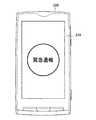
図9は、携帯端末200が表示部234に表示するユーザインタフェースの例を示す説明図である。図9は、携帯端末200を持つユーザが車両10を運転していて衝突事故を起こすなどした際に、保険会社に緊急連絡するために自動的に表示するユーザインタフェースの例である。 FIG. 9 is an explanatory diagram showing an example of a user interface displayed on the
図10は、携帯端末200が表示部234に表示するユーザインタフェースの例を示す説明図である。図10は、携帯端末200を持つユーザが車両10を駐車した際に、その駐車位置と駐車時間を表示するユーザインタフェースの例である。 FIG. 10 is an explanatory diagram showing an example of a user interface displayed on the
携帯端末200は、センサ部210が出力するセンシングデータによって車両10の動作を測定することで、上述したような様々なユーザインタフェースを表示部234に表示することができる。もちろん、携帯端末200が表示部234に表示するユーザインタフェースは係る例に限定されるものでは無い。 The
例えば、図9では携帯端末200を持つユーザが車両10を運転していて衝突事故を起こすなどのイベントが生じた際に、保険会社に緊急連絡するためのユーザインタフェースの例を示したが、他にも携帯端末200は、例えば携帯端末200の位置や、イベントが発生した時間帯に応じて様々なユーザインタフェースを表示しうる。例えば、携帯端末200の位置が、公共交通機関が通っていないような位置であれば、携帯端末200は、タクシーなどを手配するためのユーザインタフェースを自動的に表示しても良い。また例えば、イベントが発生したのが夜間であれば、携帯端末200は、ホテルを手配するためのユーザインタフェースを自動的に表示しても良い。 For example, FIG. 9 shows an example of a user interface for making an emergency contact to an insurance company when an event such as a collision accident occurs while a user having a
[1.4.変形例]
上述の説明では、携帯端末200は、車両10が走行を開始すると考えられる条件を満たした場合に限り測定部224による測定結果を記憶部240に記録しても良い旨を説明した。車両10が走行を開始すると考えられる条件としては、他にも、シートベルトの着用、イグニッションキーやスタートボタンの操作、アクセルペダルの踏み込み等が考えられる。シートベルトの着用や、イグニッションキーやスタートボタンの操作、アクセルペダルの踏み込み等に関する情報は、車両10から直接取得することが可能である。[1.4. Modification example]
In the above description, it has been explained that the
図11は、本開示の第1の実施形態の変形例を説明する説明図である。図11に示したのは、車両10の状態を車両10から取得することで、携帯端末200が測定部224による測定結果を記憶部240に記録する場合のシステム構成例である。 FIG. 11 is an explanatory diagram illustrating a modified example of the first embodiment of the present disclosure. FIG. 11 shows an example of a system configuration in which the
車両10は、車両情報取得部12を備える。車両情報取得部12は、車両10における種々の情報、例えば、シートベルトの着用、イグニッションキーやスタートボタンの操作、アクセルペダルやブレーキペダルの踏み込み、等に関する情報を取得する。車両10は、車両情報取得部12が取得した情報を、例えばOBD(On-Board Diagnostics)経由で信号出力装置100に出力したり、無線通信によって携帯端末200に出力したりする。車両情報取得部12が取得した情報を信号出力装置100が取得する場合、信号出力装置100は、取得した情報をビーコン信号に含めて出力する。 The
このように、車両情報取得部12が取得した情報を受信することで、携帯端末200は、車両情報取得部12が取得した情報を用いて、車両10が走行の開始や停止を判別することが可能となる。例えば運転者がシートベルトを着用したことが、車両情報取得部12が取得した情報から分かれば、携帯端末200は、運転者がシートベルトを着用した時点から測定部224による測定を開始してもよい。また例えば、運転者がシートベルトを外したことが、車両情報取得部12が取得した情報から分かれば、携帯端末200は、運転者がシートベルトを着用した時点から測定部224による測定を終了してもよい。 In this way, by receiving the information acquired by the vehicle
以上説明したように本開示の第1の実施形態によれば、車両10に設置された信号出力装置100からのビーコン信号の受信に応じて、センサ部210が出力するセンシングデータによって車両10の動作を測定する携帯端末200が提供される。 As described above, according to the first embodiment of the present disclosure, the operation of the
同じ走行距離であっても、走行する道路、走行状況、速度、時間帯、加減速の状態などにより事故のリスクは異なる。従って、携帯端末200に備えられているセンサ部210が出力するセンシングデータによって車両10の動作を測定することで、保険会社は、車両10の運転状況に応じた保険料の割引やキャッシュバック、または割増といったサービスを契約者に提供することが可能となる。 Even if the mileage is the same, the risk of an accident differs depending on the road, driving conditions, speed, time zone, acceleration / deceleration condition, and the like. Therefore, by measuring the operation of the
例えば、携帯端末200の測定の結果、車両10が走行した道路が一般道であれば保険会社は保険料を割り増しして、車両10が走行した道路が高速道路であれば保険会社は保険料を割り引いてもよい。 For example, as a result of measurement of the
例えば、携帯端末200の測定の結果、車両10の走行速度の変化が多ければ保険会社は保険料を割り増しして、車両10が走行速度の変化が少なければ保険会社は保険料を割り引いてもよい。 For example, as a result of measurement of the
例えば、携帯端末200の測定の結果、車両10の走行速度が100km/hを超えていれば保険会社は保険料を割り増しして、車両10の走行速度が0km/h〜50km/hの範囲であれば保険会社は保険料を割り引いてもよい。 For example, as a result of the measurement of the
例えば、携帯端末200の測定の結果、車両10の走行時間帯が20時から6時の夜間や、6時〜9時、17時〜20時の通勤時間帯等であれば保険会社は保険料を割り増しして、車両10の走行時間帯が9時から17時の比較的交通量の少ない時間帯であれば保険会社は保険料を割り引いてもよい。 For example, as a result of measurement of the
例えば、携帯端末200の測定の結果、車両10の車間時間が3秒以下での走行であれば保険会社は保険料を割り増しして、車両10の車間時間が3秒を超える走行であれば保険会社は保険料を割り引いてもよい。 For example, as a result of measurement of the
このように、保険会社は、携帯端末200が測定した車両10の動作の内容に応じて保険料の割引やキャッシュバック、または割増といったサービスを契約者に提供することが可能となる。 In this way, the insurance company can provide the policyholder with services such as discount, cash back, or premium of insurance premiums according to the content of the operation of the
<2.第2の実施形態>
続いて、本開示の第2の実施形態を説明する。
自動車の自己診断機能とは、自動車各部に取り付けられたECU(Electrical Controll Unit)にプログラミングされている機能の一つである。自動車に搭載されている診断機能という意味合いで自己診断機能と呼ばれる。また英語で自動車の自己診断機能を表す用語は、On−Board Diagnosticsの頭文字を取って、OBDと略称されている。<2. Second embodiment>
Subsequently, a second embodiment of the present disclosure will be described.
The self-diagnosis function of an automobile is one of the functions programmed in an ECU (Electrical Control Unit) attached to each part of the automobile. It is called a self-diagnosis function in the sense that it is a diagnostic function installed in automobiles. In English, the term for the self-diagnosis function of automobiles is abbreviated as OBD, which is an acronym for On-Board Diagnostics.
例えば、エンジンの燃料噴射システムを構成する各センサ及び各アクチュエータになんらかの異常が発生した場合、エンジンのECUは異常の発生を記憶し、計器盤の警告ランプを点灯させる等して、ドライバーに異常の発生を知らせる。 For example, when some abnormality occurs in each sensor and each actuator constituting the fuel injection system of the engine, the ECU of the engine memorizes the occurrence of the abnormality and turns on the warning lamp on the instrument panel to cause the driver to have an abnormality. Notify the occurrence.
OBD2は、メーカーの枠を超えて、DLC(Data link coupler)と呼ばれる同じ形状、同じピン配置の接続コネクターと、同じ故障コードを使い、故障発生時には、同じように計器盤の警告ランプを点灯させる機能を実現させた。 OBD2 goes beyond the framework of the manufacturer and uses a connector called DLC (Data link coupler) with the same shape and pin arrangement and the same failure code, and when a failure occurs, the warning lamp on the instrument panel is lit in the same way. Realized the function.
OBD2の故障コードは、DTC(Diagnostic Trouble Cord)と呼ばれ、アルファベット1文字と、4桁の数字から構成されている。4桁の数字を使えば、0000〜9999まで実に一万個の故障コードを設定することができる。 The failure code of OBD2 is called DTC (Diagnotic Trouble Code), and is composed of one letter of the alphabet and four digits. If you use a 4-digit number, you can set 10,000 fault codes from 0000 to 9999.
OBD2のDTCを読取るには、ECU内部のマイクロコンピュータと通信を取り合い、記憶されたDTCを読み取り、読み取ったDTCをディスプレイに表示する装置が必要になる。この装置をスキャンツールと呼ぶ。スキャンツールは、自動車のサービス工場や修理工場などで車両の点検、整備、修理において用いられている。しかし、プロ用機器であるため、一般のドライバーにはあまり活用されてこなかった。 In order to read the DTC of the OBD2, a device that communicates with the microcomputer inside the ECU, reads the stored DTC, and displays the read DTC on the display is required. This device is called a scan tool. Scan tools are used in vehicle inspections, maintenance, and repairs at automobile service factories and repair shops. However, since it is a professional device, it has not been widely used by general drivers.
最近では、表示装置やバッテリを持たない小型の無線または有線接続ができるスキャンツールがある。しかし、スキャンツールを使用するためには、車両に取り付けた状態でスマートフォンやPC等の通信機器や表示装置等を常に接続しておく必要がある。常時接続を行うためには、車両を使う時に常にスマートフォンやPC等を車両に持ち込んだ上で対応アプリを起動して接続しなければならず、利便性が高くない。 Nowadays, there are small wireless or wired scan tools that do not have a display or battery. However, in order to use the scan tool, it is necessary to always connect a communication device such as a smartphone or a PC, a display device, or the like while attached to the vehicle. In order to make a constant connection, it is necessary to always bring a smartphone, a PC, or the like into the vehicle when using the vehicle, and then start a compatible application to connect, which is not very convenient.
一方で、車両のエラー情報を活用して素早くトラブル対応を行うことや、実際の走行速度や加速度等の情報を活用して運転状況を知りたいというニーズがある。トラブルが起きてしまったときには、怪我人を救護したり、警察や保険会社に電話したり、相手側のさまざまな情報を確認したりと、やらなければならないことは分かっていても、トラブル直後の不安な状況でスムーズにこれらを行うのはなかなか難しいことである。そのため、トラブル時の不安を取除き、スムーズな解決をサポートすることが求められている。 On the other hand, there is a need to quickly deal with troubles by utilizing vehicle error information and to know the driving situation by utilizing information such as actual running speed and acceleration. Immediately after the trouble, even if you know that you have to do something like rescue the injured person, call the police or insurance company, check various information on the other side, etc. It is quite difficult to do these smoothly in anxious situations. Therefore, it is required to remove anxiety at the time of trouble and support a smooth solution.
具体的には、衝突事故を起こした場合に、速度変化及び加速度センサの情報を用いて自動検知し、緊急通報を自動で行う方法がある。また例えば、エンジンのエラーランプが点灯した場合に、車両情報を活用して適切なロードサービスや修理工場の手配を行う方法がある。また例えば、運転状況を保険料算出や中古車の車両価格の算出に活用するなどの方法がある。これらの方法を実現するために必要とされるスキャンツールは、小型で車両から取り外した状態でも必要な情報を簡単に確認が出来て、さらにデータの改竄を防ぐことができ、スマートフォン等との常時接続を必要としないで使用可能な機器が求められている。さらに、トラブル時発生時には素早く異常状態を連絡し、緊急対応を行う機能も合わせて持つ必要がある。 Specifically, when a collision accident occurs, there is a method of automatically detecting an emergency call by using information of a speed change and an acceleration sensor. Further, for example, when the error lamp of the engine lights up, there is a method of arranging an appropriate road service or repair shop by utilizing the vehicle information. Further, for example, there is a method of utilizing the driving situation for calculating the insurance premium and the vehicle price of the used car. The scan tool required to realize these methods is small and can easily check the necessary information even when it is removed from the vehicle, and it can prevent data tampering, and it is always with smartphones etc. There is a demand for equipment that can be used without the need for connection. Furthermore, when a trouble occurs, it is necessary to have a function to quickly notify the abnormal state and take an emergency response.
そこで、本開示の第2の実施形態では、自動車の自己診断機能の情報を取得すると共に、内部のセンサによって車両10の動作をセンシングするドライブカウンタを説明する。 Therefore, in the second embodiment of the present disclosure, a drive counter that acquires information on the self-diagnosis function of the automobile and senses the operation of the
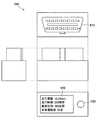
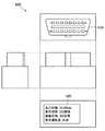
図12は、本開示の第2の実施形態に係るドライブカウンタ400の外観例を示す説明図である。本開示の第2の実施形態に係るドライブカウンタ400は、OBD2を読み取るDTC(Data link coupler)端子410、表示部420、操作ボタン430を備える。また本開示の第2の実施形態に係るドライブカウンタ400は、内部にセンサ、不揮発性メモリ、時計機能、バッテリ、通信部等を備える。 FIG. 12 is an explanatory view showing an external example of the
自動車の車両状態は、自動車の自己診断機能(OBD/OBD2)の情報を、DTCなどの接続コネクターを介してDTC端子410を経由して取得する。さらに、ドライブカウンタ400に内蔵されるセンサは、加速度、ジャイロ、地磁気、電圧検出、温度、気圧/高度、湿度、GPS、マイク等を含み、これらのセンサを介して車両状態の情報を取得する。そして、ドライブカウンタ400から取得した自動車の車両状態に基づき、ドライブカウンタ400を車両に装着している間の装着時間、走行距離、走行時間、平均速度、安全運転度、衝突情報、エラー情報等の算出を行う。ドライブカウンタ400は、算出した情報を、必要に応じてハッシュ値に変換するなどの改竄防止処理を行った上で、不揮発性メモリに保存する。またドライブカウンタ400は、バッテリを内蔵することで、車両から取り外して時計機能などを含めて単体で動作できる。またドライブカウンタ400は、USB等の有線接続やBluetooth、Wi−Fi、NFC、ビーコン送出等の無線通信により、PCやスマートフォン等に情報を出力できる。またドライブカウンタ400は、液晶ディスプレイや電子ペーパー等の表示部420に情報を出力することで、PCやスマートフォン等がなくても使うことができる。ドライブカウンタ400が出力する情報を用いて保険料算出や車両価格算出、トラブル時の原因解析などに活用すると共に、出力情報が改竄されていないことを確認できる仕組みを持つ。 The vehicle state of the automobile acquires the information of the self-diagnosis function (OBD / OBD2) of the automobile via the
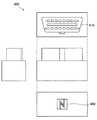
図13は、本開示の第2の実施形態に係るドライブカウンタ400の外観例を示す説明図である。図13に示したドライブカウンタ400は、USB端子440を備える。図13に示したドライブカウンタ400は、USB端子440を用いることで、有線通信を行うと共にUSB経由で電源を給電できる。従って図13に示したドライブカウンタ400は、車両に取り付けた状態だけでなく車両から取り外した状態においても、PCやスマートフォン等でドライブカウンタの情報を確認することが出来る。 FIG. 13 is an explanatory view showing an external example of the
図14は、本開示の第2の実施形態に係るドライブカウンタ400の外観例を示す説明図である。図14に示したドライブカウンタ400は、NFC受信アンテナ450を備える。図14に示したドライブカウンタ400は、NFC受信アンテナ450を用いることで、近接無線通信を行うだけでなく、ワイヤレス給電で電源を給電できる。従って図14に示したドライブカウンタ400は、車両に取り付けた状態だけでなく車両から取り外した状態においても、PCやスマートフォン等でドライブカウンタの情報を確認することが出来る。 FIG. 14 is an explanatory view showing an external example of the
図15は、本開示の第2の実施形態に係るドライブカウンタ400の外観例を示す説明図である。図15に示したドライブカウンタ400は、例えば電子ペーパーや液晶ディスプレイ、有機ELディスプレイなどで構成される表示部420を備えている。図15に示したドライブカウンタ400は、表示部420を備えることで、車両に取り付けた状態だけでなく車両から取り外した状態においてもドライブカウンタの情報を確認することが出来る。 FIG. 15 is an explanatory view showing an external example of the
図16は、本開示の第2の実施形態に係るドライブカウンタ400の外観例を示す説明図である。図16に示したドライブカウンタ400は、操作ボタン430を備える。図15に示したドライブカウンタ400は、操作ボタン430を備えることで、車両に取り付けた状態だけでなく車両から取り外した状態においてもドライブカウンタ400に対する操作の受け付けが可能になる。 FIG. 16 is an explanatory view showing an external example of the
図17は、本開示の第2の実施形態に係るドライブカウンタ400の外観例を示す説明図である。図17に示したドライブカウンタ400は、バッテリ(図示せず)を備える。図17に示したドライブカウンタ400は、バッテリを内蔵することで、車両から取り外して単体でも動作できる。ドライブカウンタ400は、バッテリを内蔵して単体で動作ができることで、車両取り付け後に時計機能の時刻合わせが不要になり、時計機能の利便性が向上する。具体的には、運転時間を測定する機能、ドライブカウンタ400本体を車両から取り外した着脱時間を測定する機能等を使うことができる。さらにドライブカウンタ400は、車両から取り外した状態においても通信機能や表示機能を使うことができる。 FIG. 17 is an explanatory view showing an external example of the
このように、ドライブカウンタ400は、車両情報を車両から簡単に入手でき、車両の走行状況を可視化することが出来る。ドライブカウンタ400は、可視化したデータを用いることで、状況に応じた解決策をドライバーに提供できる。ドライブカウンタ400は、従来の電話でのサポートだけでなく、もっとドライバーに近いところでサポートが出来ることで、トラブル時の不安をドライバーから取り除き、ドライバーに安心を提供することが出来る。 In this way, the
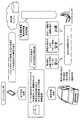
具体的には、ドライブカウンタ400は、車両が交通事故を起こした場合に衝撃を検知し、ユーザが所持するスマートフォンなどの携帯端末でアプリを自動的に起動させて、トラブル発生時にユーザをサポートすることができる。ドライブカウンタ400は、大きな衝撃を検出した場合は、ユーザが所持するスマートフォンなどの携帯端末で、自動で緊急連絡先等に連絡することができる。さらにドライブカウンタ400は、ロードサービスに車両状態を事前通知することで、適切な手配を迅速に行うことができる。またドライブカウンタ400に記録された事故直前及び直後の走行状態を用いることで、ユーザは、事故後の保険金や示談交渉などが迅速化できる。 Specifically, the
また例えば、車両のエンジンが掛らないトラブルが起きた場合に、ドライブカウンタ400を通じて車両の状態を遠隔から診断することで、トラブルの原因となった個所を特定することができる。例えば、ドライブカウンタ400がセンターに送信したデータによれば、低温によるバッテリ電圧低下がトラブルの原因と判明したので、センターはバッテリ温度を温める対処法をユーザに通知することができる。従って、ユーザはロードサービスを呼ばずにその場ですぐに解決することができる。またセンターは、遠隔からの診断を用いることでロードサービスを抑制しコストを削減することが可能になる。 Further, for example, when a trouble occurs in which the engine of the vehicle does not start, the location where the trouble is caused can be identified by remotely diagnosing the state of the vehicle through the
図18〜図21は、ドライブカウンタ400を車両に接続することによる効果を示す説明図である。図18は、ドライブカウンタ400が所定のビーコンを送出し、ビーコンを受信した車載機器、道路上のセンサ、スマートフォンなどが、緊急センターへ通報を行う様子を示している。 18 to 21 are explanatory views showing the effect of connecting the
図19は、ドライブカウンタ400から走行状態を取得したスマートフォンが、その走行状態を保険会社に送信し、保険会社が走行状態に応じて適切な保険料を算出する様子を示している。 FIG. 19 shows a state in which a smartphone that has acquired a running state from the
図20は、ドライブカウンタ400から走行状態を取得したスマートフォンが、その走行状態を保険会社に送信し、自動車販売会社が走行状態に応じて適切な車両価格を算出する様子を示している。 FIG. 20 shows a state in which a smartphone that has acquired a driving state from the
図21は、ドライブカウンタ400から走行状態を取得したスマートフォンが、その走行状態を保険会社に送信し、自動車販売会社が走行状態に応じて適切なアドバイスやサポートを提供する様子を示している。 FIG. 21 shows a state in which a smartphone that has acquired a driving state from the
本開示の第2の実施形態に係るドライブカウンタ400が提供することが出来る機能は概ね以下の通りである。ドライブカウンタ400は、取得した車両の情報を内部の不揮発性メモリに記録することで、外部のサーバなどと常時接続する必要がなく、後から任意のタイミングで通信機能を用いて外部に送信することが可能となる。 The functions that can be provided by the
またドライブカウンタ400は、車両に装着及び着脱したことを電圧等で識別して、内蔵する時計機能により装着時間を測定し記録することが可能となる。 Further, the
またドライブカウンタ400は、取得した車両の情報に基づき、接続した車両を識別して、車両ごとに区別して情報を記録することが可能となる。 Further, the
またドライブカウンタ400は、取得した車両の速度情報と内蔵する時計機能とにより、平均速度及び最高速度を測定し記録することが可能となる。 Further, the
またドライブカウンタ400は、取得した車両の速度情報と内蔵する時計機能とにより、走行距離を測定し記録することが可能となる。 Further, the
またドライブカウンタ400は、取得した車両の速度情報と内蔵する時計機能とにより、走行時間及び走行回数を測定し記録することが可能となる。 Further, the
またドライブカウンタ400は、取得した車両の速度情報と内蔵する時計機能により、車両の加速度及び減速度及びその回数を測定し記録することが可能となる。 Further, the
またドライブカウンタ400は、車両への装着時間、車両の走行距離、車両の走行時間、車両の平均速度、車両の加速度及び減速度並びに加減速の回数などから算出する安全運転度を記録することが可能となる。 Further, the
またドライブカウンタ400は、車両情報及び算出した情報を常に一次メモリに保存しておき、車両情報が事前に設定した閾値を超えた場合やエラーメッセージが生じた場合に、発生前後の詳細な情報を不揮発性メモリに記録することが可能となる。 Further, the
またドライブカウンタ400は、データの改ざんを防止するため、車両情報及び算出した情報をハッシュ値に変換する等の改ざん防止処理を行ってから不揮発性メモリに記録したり、通信機能を用いて出力したりすることが可能となる。 Further, in order to prevent falsification of data, the
またドライブカウンタ400は、車両から取得した情報を基に車両の異常を検知した場合には、通信機能を用いて異常状態を伝える通信を行うことが可能となる。 Further, when the
またドライブカウンタ400は、車両から取り外された場合にも、外部通信機器からの電力により、不揮発性メモリの情報を読み出せることが可能となる。 Further, even when the
またドライブカウンタ400は、電子ペーパー等の不揮発性表示装置に出力情報を表示することで、当機器を車両から取り外した時にも情報を読み出せることが可能となる。 Further, the
またドライブカウンタ400は、バッテリを内蔵することで、車両から取り外された場合にも、通信機能を介して情報を読み出せることが可能となる。 Further, since the
またバッテリを内蔵したドライブカウンタ400は、車両に装着及び着脱したことを電圧等で識別して、内蔵する時計機能により当機器を車両に装着している時間及び着脱している時間を測定し記録することが可能となる。 In addition, the
またバッテリを内蔵したドライブカウンタ400は、取得した車両の速度情報と内蔵する時計機能とにより、車両走行している時刻を記録することが可能となる。 Further, the
またバッテリを内蔵したドライブカウンタ400は、外部通信機器との間の通信により、内蔵する時計の時刻設定および修正が可能となる。 Further, the
またドライブカウンタ400は、加速度センサ、ジャイロセンサ、地磁気センサ、電圧センサ、温度センサ、気圧センサ、湿度センサ、GPS、GNSS等の内蔵センサより取得した値を不揮発性メモリに記録することで、外部のサーバなどと常時接続する必要がなく、後から任意のタイミングで通信機能を用いて外部に送信することが可能となる。 Further, the drive counter 400 records values acquired from built-in sensors such as an acceleration sensor, a gyro sensor, a geomagnetic sensor, a voltage sensor, a temperature sensor, a pressure sensor, a humidity sensor, GPS, and a GNSS in a non-volatile memory, thereby externally recording the values. It is not necessary to always connect to a server or the like, and it is possible to transmit to the outside using the communication function at an arbitrary timing later.
またドライブカウンタ400は、内蔵センサにより取得した値が事前に設定した閾値を超えた場合には、発生前後の詳細な内蔵センサ情報及び車両情報を不揮発性メモリに記録することが可能となる。 Further, when the value acquired by the built-in sensor exceeds a preset threshold value, the
またドライブカウンタ400は、車両への着脱を内蔵センサの値の変化により識別して、内蔵する時計機能により装着時間を測定し記録することが可能となる。 Further, the
またドライブカウンタ400は、内蔵センサにより取得した値が事前に設定した閾値を超えた場合には、通信機能を用いて、異常状態を伝える通信を行うことが可能となる。 Further, when the value acquired by the built-in sensor exceeds a preset threshold value, the
またドライブカウンタ400は、異常を検知して事前に設定した閾値を超えた緊急状態の場合には、通信機能を用いて、異常状態を伝えるビーコン送出を行うことが可能となる。ドライブカウンタ400がビーコンを送出することで、近くにある車載機器や道路上のセンサ、近くにいる人のスマートフォン等がビーコンを受信することができる。そしてビーコンを受信した機器の通信機能を使ってセンター等への連絡をすることが可能となる。 Further, in the case of an emergency state in which the
またドライブカウンタ400からの緊急状態のビーコンを受けた受信した機器は、GPSやGNSS等の位置情報を付加してセンター等への連絡をすることが可能となる。またドライブカウンタ400からの緊急状態のビーコンを受けた受信した機器は、GPSやGNSS等の位置情報を付加してビーコンを再送出することで、局所的に緊急状態を連絡することが可能となる。 Further, the receiving device that has received the emergency beacon from the
またドライブカウンタ400は、算出した装着時間、走行距離、走行時間、平均速度、安全運転度、衝突情報、エラー情報等を用いて事故リスクを算出することが出来る。保険会社は、ドライブカウンタ400が算出した事故リスクに応じた保険料係数または保険料割引、割増の割合または保険料キャッシュバックの割合を算出することが出来る。また保険会社は、ドライブカウンタ400が算出した出力情報が改竄されていないことを確認できる。 Further, the
またドライブカウンタ400は、算出した装着時間、走行距離、走行時間、平均速度、安全運転度、衝突情報、エラー情報等を用いて車両の状態を正確に算出することが出来る。保険会社は、ドライブカウンタ400が算出した車両の状態に応じた車両価格係数または車両割引、割増の割合または車両キャッシュバックの割合を算出することが出来る。また保険会社は、ドライブカウンタ400が算出した出力情報が改竄されていないことを確認できる。 Further, the
またドライブカウンタ400は、算出した装着時間、走行距離、走行時間、平均速度、安全運転度、衝突情報、エラー情報等を用いて、トラブル発生時に必要な手配を自動又はステップバイステップで行うことが出来る。トラブル時に必要な手配とは、例えば、緊急通報、コールサポート、怪我人の救護サポート、リモート診断、ロードサービス手配、ガソリンスタンド案内、コンビニエンスストア案内、修理工場手配、代車手配、タクシーまたはハイヤー手配、レンタカー手配、交通手配、ホテル(宿泊)手配等である。 Further, the
またドライブカウンタ400は、通信機能を用いて内部の不揮発性メモリに保存した情報を読み書きするときに、認証機能を用いてユーザ認証を行うことで、情報のアクセス出来る範囲を制限しアクセス権限を管理することが出来る。 Further, when the
上述したドライブカウンタ400の機能は一例であり、図12〜16に示したドライブカウンタ400が実現できる機能は係る例に限定されるものでは無い。 The function of the
<3.まとめ>
以上説明したように、本開示の実施の形態によれば、移動体である車両の挙動に関する高精度の情報を取得することが可能となる。<3. Summary>
As described above, according to the embodiment of the present disclosure, it is possible to acquire highly accurate information on the behavior of the vehicle which is a moving body.
本開示の第1の実施の形態によれば、移動体からの記録指示に応じてセンシングを開始して、センシングにより移動体の挙動に関するデータを記録し、記録したデータを外部の装置に送信する携帯端末200が提供される。 According to the first embodiment of the present disclosure, sensing is started in response to a recording instruction from the moving body, data on the behavior of the moving body is recorded by the sensing, and the recorded data is transmitted to an external device. A
また本開示の第2の実施の形態によれば、移動体に接続した状態で、センシングにより移動体の挙動に関するデータを記録し、記録したデータを外部の装置に送信するドライブカウンタ400が提供される。 Further, according to the second embodiment of the present disclosure, there is provided a
本明細書の各装置が実行する処理における各ステップは、必ずしもシーケンス図またはフローチャートとして記載された順序に沿って時系列に処理する必要はない。例えば、各装置が実行する処理における各ステップは、フローチャートとして記載した順序と異なる順序で処理されても、並列的に処理されてもよい。 Each step in the process performed by each device of the present specification does not necessarily have to be processed in chronological order in the order described as a sequence diagram or a flowchart. For example, each step in the process executed by each device may be processed in an order different from the order described in the flowchart, or may be processed in parallel.
また、各装置に内蔵されるCPU、ROMおよびRAMなどのハードウェアを、上述した各装置の構成と同等の機能を発揮させるためのコンピュータプログラムも作成可能である。また、該コンピュータプログラムを記憶させた記憶媒体も提供されることが可能である。また、機能ブロック図で示したそれぞれの機能ブロックをハードウェアまたはハードウェア回路で構成することで、一連の処理をハードウェアまたはハードウェア回路で実現することもできる。 It is also possible to create a computer program for making the hardware such as the CPU, ROM, and RAM built in each device exhibit the same functions as the configuration of each device described above. It is also possible to provide a storage medium in which the computer program is stored. Further, by configuring each functional block shown in the functional block diagram with hardware or a hardware circuit, a series of processes can be realized by the hardware or the hardware circuit.
また上述の説明で用いた機能ブロック図で示したそれぞれの機能ブロックの一部又は全部は、たとえばインターネット等のネットワークを介して接続されるサーバ装置で実現されてもよい。また上述の説明で用いた機能ブロック図で示したそれぞれの機能ブロックの構成は、単独の装置で実現されてもよく、複数の装置が連携するシステムで実現されても良い。複数の装置が連携するシステムには、例えば複数のサーバ装置の組み合わせ、サーバ装置と端末装置との組み合わせ等が含まれ得る。 Further, a part or all of each functional block shown in the functional block diagram used in the above description may be realized by a server device connected via a network such as the Internet. Further, the configuration of each functional block shown in the functional block diagram used in the above description may be realized by a single device or a system in which a plurality of devices are linked. A system in which a plurality of devices are linked may include, for example, a combination of a plurality of server devices, a combination of a server device and a terminal device, and the like.
以上、添付図面を参照しながら本開示の好適な実施形態について詳細に説明したが、本開示の技術的範囲はかかる例に限定されない。本開示の技術分野における通常の知識を有する者であれば、特許請求の範囲に記載された技術的思想の範疇内において、各種の変更例または修正例に想到し得ることは明らかであり、これらについても、当然に本開示の技術的範囲に属するものと了解される。 Although the preferred embodiments of the present disclosure have been described in detail with reference to the accompanying drawings, the technical scope of the present disclosure is not limited to such examples. It is clear that a person having ordinary knowledge in the technical field of the present disclosure can come up with various modifications or modifications within the scope of the technical ideas described in the claims. Of course, it is understood that the above also belongs to the technical scope of the present disclosure.
また、本明細書に記載された効果は、あくまで説明的または例示的なものであって限定的ではない。つまり、本開示に係る技術は、上記の効果とともに、または上記の効果に代えて、本明細書の記載から当業者には明らかな他の効果を奏しうる。 In addition, the effects described herein are merely explanatory or exemplary and are not limited. That is, the techniques according to the present disclosure may exhibit other effects apparent to those skilled in the art from the description herein, in addition to or in place of the above effects.
なお、以下のような構成も本開示の技術的範囲に属する。
(1)
センシングによるデータを出力するセンシング部と、
移動体からの記録指示に応じて前記センシング部が出力する前記移動体の挙動に関するデータの記録を開始し、前記移動体からの記録指示の途絶に応じて前記センシング部が出力する前記移動体の挙動に関するデータの記録を終了する記録部と、
前記記録部が記録したデータを外部の装置に送信する送信部と、
を備える、記録装置。
(2)
前記記録部は、予め割り当てられた識別情報と、前記記録指示に含まれる識別情報とが一致していることを条件に前記データを記録する、前記(1)に記載の記録装置。
(3)
前記記録部は、前記センシング部のセンシングによるデータが所定の条件を満たした場合を条件に前記データの記録を開始する、前記(1)または(2)に記載の記録装置。
(4)
前記記録部は、前記センシング部のセンシングによるデータにより静止状態を検出したことを条件に前記データの記録を開始する、前記(3)に記載の記録装置。
(5)
前記記録部は、前記センシング部のセンシングによるデータにより所定の気圧変化を検出したことを条件に前記データの記録を開始する、前記(3)に記載の記録装置。
(6)
前記記録部は、前記センシング部のセンシングによるデータにより所定の位置からの移動を検出したことを条件に前記データの記録を開始する、前記(3)に記載の記録装置。
(7)
前記センシング部のセンシングによるデータを用いて、前記移動体内での静止の有無を判別する判別部をさらに備える、前記(1)〜(6)のいずれかに記載の記録装置。
(8)
前記判別部は、前記移動体内で静止していないと判別した場合、前記移動体がセンシングしたデータと、前記センシング部のセンシングによるデータとの差分によって前記移動体内での状態を判断する、前記(7)に記載の記録装置。
(9)
前記判別部は、前記センシング部のセンシングによるデータに基づいて操作の対象者を判別する、前記(7)に記載の記録装置。
(10)
前記センシング部のセンシングにより所定のイベントの発生の有無を検出するイベント検出部をさらに備える、前記(1)〜(9)のいずれかに記載の記録装置。
(11)
前記イベント検出部は、前記センシング部のセンシングにより前記移動体の物体への衝突の有無を検出する、前記(10)に記載の記録装置。
(12)
前記イベント検出部が検出したイベントに応じた画面を表示させる表示制御部を備える、前記(10)または(11)に記載の記録装置。
(13)
前記移動体の走行距離の情報を入力させる画面を所定の時に表示させる表示制御部を備える、前記(1)〜(12)のいずれかに記載の記録装置。
(14)
所定の期間における前記センシング部のセンシングによるデータに基づいて前記移動体の走行に関する情報を表示させる表示制御部を備える、前記(1)〜(13)のいずれかに記載の記録装置。
(15)
前記表示制御部は、前記送信部が前記外部の装置に送信したデータに基づいて前記外部の装置で生成されて該外部の装置から送信された、前記移動体の運転に関する情報を表示させる、前記(14)に記載の記録装置。
(16)
前記センシング部のセンシングに基づき、前記移動体の周辺の施設の情報を表示させる表示制御部を備える、前記(1)〜(15)のいずれかに記載の記録装置。
(17)
前記センシング部は少なくとも加速度センサを含み、
当該記録装置が前記移動体に載置され、前記センシング部は前記移動体の挙動に応じたデータを出力する、前記(1)に記載の記録装置。
(18)
前記記録制御部は、前記センシング部のセンシングによるデータにより当該記録装置に対するユーザの操作を検出したことを条件に前記データの記録を停止する、前記(3)に記載の記録装置。
(19)
前記記録制御部は、前記信号発信装置からの無線信号及び前記センシング部のセンシングによるデータに基づいて判別された当該記録装置の状態に基づいて、前記センシング部が出力するデータの記録開始及び記録停止を制御する前記(1)に記載の記録装置。
(20)
移動体からの記録指示に応じてセンシングを開始することと、
前記センシングの開始により生じる、前記移動体の挙動に関するデータを記録することと、
記録した前記データを外部の装置に送信することと、
前記移動体からの記録指示の途絶に応じてセンシングを終了することと、
を含む、記録方法。
(21)
コンピュータに、
移動体からの記録指示に応じてセンシングを開始することと、
前記センシングの開始により生じる、前記移動体の挙動に関するデータを記録することと、
記録した前記データを外部の装置に送信することと、
前記移動体からの記録指示の途絶に応じてセンシングを終了することと、
を実行させる、コンピュータプログラム。The following configurations also belong to the technical scope of the present disclosure.
(1)
A sensing unit that outputs sensing data and
Recording of data related to the behavior of the moving body output by the sensing unit is started in response to a recording instruction from the moving body, and the moving body output by the sensing unit in response to interruption of the recording instruction from the moving body. A recording unit that finishes recording data related to behavior,
A transmission unit that transmits the data recorded by the recording unit to an external device, and a transmission unit.
A recording device.
(2)
The recording device according to (1) above, wherein the recording unit records the data on condition that the identification information assigned in advance and the identification information included in the recording instruction match.
(3)
The recording device according to (1) or (2) above, wherein the recording unit starts recording the data on the condition that the data obtained by the sensing of the sensing unit satisfies a predetermined condition.
(4)
The recording device according to (3) above, wherein the recording unit starts recording the data on condition that the stationary state is detected by the data obtained by the sensing of the sensing unit.
(5)
The recording device according to (3) above, wherein the recording unit starts recording the data on condition that a predetermined atmospheric pressure change is detected by the data obtained by the sensing of the sensing unit.
(6)
The recording device according to (3) above, wherein the recording unit starts recording the data on condition that the movement from a predetermined position is detected by the data obtained by the sensing of the sensing unit.
(7)
The recording device according to any one of (1) to (6) above, further comprising a discriminating unit for discriminating the presence or absence of rest in the moving body by using the data obtained by the sensing of the sensing unit.
(8)
When the discriminating unit determines that it is not stationary in the moving body, the discriminating unit determines the state in the moving body based on the difference between the data sensed by the moving body and the data sensed by the sensing unit. The recording device according to 7).
(9)
The recording device according to (7) above, wherein the discrimination unit discriminates a target person for operation based on data obtained by sensing of the sensing unit.
(10)
The recording device according to any one of (1) to (9) above, further comprising an event detection unit that detects the presence or absence of the occurrence of a predetermined event by sensing of the sensing unit.
(11)
The recording device according to (10) above, wherein the event detection unit detects the presence or absence of a collision of the moving object with an object by sensing the sensing unit.
(12)
The recording device according to (10) or (11), further comprising a display control unit that displays a screen corresponding to an event detected by the event detection unit.
(13)
The recording device according to any one of (1) to (12), further comprising a display control unit for displaying a screen for inputting information on the mileage of the moving body at a predetermined time.
(14)
The recording device according to any one of (1) to (13), further comprising a display control unit that displays information on the traveling of the moving body based on data obtained by sensing of the sensing unit in a predetermined period.
(15)
The display control unit displays information on the operation of the moving body, which is generated by the external device and transmitted from the external device based on the data transmitted by the transmission unit to the external device. The recording device according to (14).
(16)
The recording device according to any one of (1) to (15), further comprising a display control unit that displays information on facilities around the moving body based on the sensing of the sensing unit.
(17)
The sensing unit includes at least an acceleration sensor.
The recording device according to (1) above, wherein the recording device is mounted on the moving body, and the sensing unit outputs data according to the behavior of the moving body.
(18)
The recording device according to (3) above, wherein the recording control unit stops recording of the data on condition that the user's operation on the recording device is detected by the data obtained by the sensing of the sensing unit.
(19)
The recording control unit starts recording and stops recording of data output by the sensing unit based on the state of the recording device determined based on the radio signal from the signal transmitting device and the data obtained by the sensing of the sensing unit. The recording device according to (1) above.
(20)
Starting sensing in response to a recording instruction from a moving object,
Recording data on the behavior of the moving object resulting from the initiation of the sensing
Sending the recorded data to an external device and
When the sensing is terminated in response to the interruption of the recording instruction from the moving body,
Recording methods, including.
(21)
On the computer
Starting sensing in response to a recording instruction from a moving object,
Recording data on the behavior of the moving object resulting from the initiation of the sensing
Sending the recorded data to an external device and
When the sensing is terminated in response to the interruption of the recording instruction from the moving body,
A computer program that runs.
10 車両
100 信号出力装置
200 携帯端末
400 ドライブカウンタ10
Claims (16)
Translated fromJapanese移動体に備えられた信号発信装置からの無線信号を受信する受信部と、
前記受信部より受信した前記信号発信装置からの無線信号に応じて、前記センシング部が測定するデータの記録開始及び記録停止を制御する記録制御部と、
前記記録制御部の制御により記録されたデータを外部の装置に送信する送信部と、
を備え、
前記記録制御部は、前記センシング部により測定されたデータが所定の条件を満たし、所定の状態を検出したことおよび周囲の所定の環境状態を検出したことの少なくともいずれかの場合に、前記データの記録を開始し、
前記所定の条件は、前記データにより所定の位置からの移動を検出したこと、前記データにより静止状態を検出したこと、および前記データにより所定の気圧変化を検出したことのいずれか1以上である
記録装置。A sensing unit thatmeasures and outputs data fromsensor sensing,
A receiver that receives radio signals from a signal transmitter installed in a mobile body,
A recording control unit that controls recording start and recording stop of datameasured by the sensing unit in response to a wireless signal from the signal transmitting device received from the receiving unit.
A transmission unit that transmits data recorded under the control of the recording control unit to an external device, and a transmission unit.
With
Whenthe datameasured by the sensing unit satisfies a predetermined condition and detects a predetermined state and detects a predetermined environmental state in the surroundings, the recording control unit obtains the data. Start recording,
The predetermined condition is one or more of the detection of movement from a predetermined position by the data, the detection of a stationary state by the data, and the detection of a predetermined atmospheric pressure change by the data. apparatus.
当該記録装置が前記移動体に載置され、前記センシング部は前記移動体の挙動に応じたデータを測定する、請求項1に記載の記録装置。Thesensor includes at least an accelerometer.
The recording device according to claim 1, wherein the recording device is mounted on the moving body, and the sensing unitmeasures data according to the behavior of the moving body.
前記センシングにより得られる、移動体の挙動に関するデータを記録することと、
記録された前記データを外部の装置に送信することと、
前記移動体に備えられた信号発信装置からの無線信号に応じて測定された前記データの記録開始および記録停止を制御することと、
前記センシングにより得られるデータが所定の条件を満たし、所定の状態を検出したことおよび周囲の所定の環境状態を検出したことの少なくともいずれかの場合に、前記データの記録を開始することと、
を含み、
前記所定の条件は、前記データにより所定の位置からの移動を検出したこと、前記データにより静止状態を検出したこと、および前記データにより所定の気圧変化を検出したことのいずれか1以上である
記録方法。Measuring data bysensor sensing and
Recording the data on the behavior of the moving object obtained by the sensing
Sending the recorded data to an external device and
Controlling the recording start and recording stop of the datameasured according to the radio signal from the signal transmitting device provided in the moving body, and
When the data obtained by the sensing satisfies a predetermined condition and a predetermined state is detected and at least one of the surrounding predetermined environmental conditions is detected, the recording of the data is started.
Only including,
The predetermined condition is one or more of the detection of movement from a predetermined position by the data, the detection of a stationary state by the data, and the detection of a predetermined atmospheric pressure change by the data. Method.
センサのセンシングによるデータを測定することと、
前記センシングにより得られる、移動体の挙動に関するデータを記録することと、
記録された前記データを外部の装置に送信することと、
前記移動体に備えられた信号発信装置からの無線信号に応じて測定された前記データの記録開始および記録停止を制御することと、
前記センシングにより得られるデータが所定の条件を満たし、所定の状態を検出したことおよび周囲の所定の環境状態を検出したことの少なくともいずれかの場合に、前記データの記録を開始することと、
を実行させ、
前記所定の条件は、前記データにより所定の位置からの移動を検出したこと、前記データにより静止状態を検出したこと、および前記データにより所定の気圧変化を検出したことのいずれか1以上である
コンピュータプログラム。On the computer
Measuring data bysensor sensing and
Recording the data on the behavior of the moving object obtained by the sensing
Sending the recorded data to an external device and
Controlling the recording start and recording stop of the datameasured according to the radio signal from the signal transmitting device provided in the moving body, and
When the data obtained by the sensing satisfies a predetermined condition and a predetermined state is detected and at least one of the surrounding predetermined environmental conditions is detected, the recording of the data is started.
To execute,
The predetermined condition is one or more of the detection of movement from a predetermined position by the data, the detection of a stationary state by the data, and the detection of a predetermined atmospheric pressure change by the data. program.
Applications Claiming Priority (3)
| Application Number | Priority Date | Filing Date | Title |
|---|---|---|---|
| US201562129688P | 2015-03-06 | 2015-03-06 | |
| US62/129,688 | 2015-03-06 | ||
| PCT/JP2016/055786WO2016143552A1 (en) | 2015-03-06 | 2016-02-26 | Recording device, recording method, and computer program |
Publications (2)
| Publication Number | Publication Date |
|---|---|
| JPWO2016143552A1 JPWO2016143552A1 (en) | 2018-01-11 |
| JP6773024B2true JP6773024B2 (en) | 2020-10-21 |
Family
ID=56880320
Family Applications (1)
| Application Number | Title | Priority Date | Filing Date |
|---|---|---|---|
| JP2017504973AActiveJP6773024B2 (en) | 2015-03-06 | 2016-02-26 | Recording device, recording method and computer program |
Country Status (3)
| Country | Link |
|---|---|
| US (2) | US10825271B2 (en) |
| JP (1) | JP6773024B2 (en) |
| WO (1) | WO2016143552A1 (en) |
Families Citing this family (15)
| Publication number | Priority date | Publication date | Assignee | Title |
|---|---|---|---|---|
| US10341309B1 (en)* | 2016-06-13 | 2019-07-02 | Allstate Insurance Company | Cryptographically protecting data transferred between spatially distributed computing devices using an intermediary database |
| US11184475B2 (en)* | 2017-03-29 | 2021-11-23 | Pioneer Corporation | Mobile apparatus, terminal apparatus, information processing system, information processing method, program for mobile apparatus, and program for terminal apparatus |
| US10672203B2 (en)* | 2017-07-07 | 2020-06-02 | Toyota Jidosha Kabushiki Kaisha | Olfactory-based vehicle diagnostics |
| JP6396546B1 (en)* | 2017-07-12 | 2018-09-26 | ヤフー株式会社 | Providing device, providing method, and providing program |
| US10567512B2 (en)* | 2017-10-13 | 2020-02-18 | GM Global Technology Operations LLC | Systems and methods to aggregate vehicle data from infotainment application accessories |
| JP2019101452A (en)* | 2017-11-28 | 2019-06-24 | 株式会社Nttドコモ | Information distribution device |
| JP7062942B2 (en)* | 2017-12-21 | 2022-05-09 | トヨタ自動車株式会社 | Parking agency service management device, its usage support method, and program |
| US20190354838A1 (en)* | 2018-05-21 | 2019-11-21 | Uber Technologies, Inc. | Automobile Accident Detection Using Machine Learned Model |
| EP3629270A1 (en) | 2018-09-28 | 2020-04-01 | Konekt ApS | Automatic parking system |
| JP7152288B2 (en)* | 2018-12-11 | 2022-10-12 | 株式会社Mobility Technologies | System, method and program for providing content |
| JP7115338B2 (en)* | 2019-01-25 | 2022-08-09 | トヨタ自動車株式会社 | electric vehicle |
| US10757248B1 (en)* | 2019-03-22 | 2020-08-25 | International Business Machines Corporation | Identifying location of mobile phones in a vehicle |
| US12219441B2 (en)* | 2019-10-21 | 2025-02-04 | Nec Corporation | Module management system, module management method, and program |
| JP7380409B2 (en)* | 2020-04-29 | 2023-11-15 | 株式会社デンソー | Vehicle recording device, information recording method |
| JP2023092977A (en)* | 2021-12-22 | 2023-07-04 | Eneos株式会社 | Information processing system, server and information processing method |
Family Cites Families (108)
| Publication number | Priority date | Publication date | Assignee | Title |
|---|---|---|---|---|
| US29696A (en)* | 1860-08-21 | Heney a | ||
| US7426264B1 (en)* | 1994-01-05 | 2008-09-16 | Henderson Daniel A | Method and apparatus for improved personal communication devices and systems |
| US7266186B1 (en)* | 1994-01-05 | 2007-09-04 | Intellect Wireless Inc. | Method and apparatus for improved paging receiver and system |
| US5646349A (en)* | 1994-02-18 | 1997-07-08 | Plan B Enterprises, Inc. | Floating mass accelerometer |
| US5524489A (en)* | 1994-02-18 | 1996-06-11 | Plan B Enterprises, Inc. | Floating mass accelerometer |
| US5497419A (en)* | 1994-04-19 | 1996-03-05 | Prima Facie, Inc. | Method and apparatus for recording sensor data |
| JPH08140028A (en)* | 1994-11-10 | 1996-05-31 | Mitsubishi Electric Corp | Magnetic recording / reproducing device |
| US6073062A (en)* | 1995-05-31 | 2000-06-06 | Fujitsu Limited | Mobile terminal and moving body operation management system |
| US6526341B1 (en)* | 1999-06-10 | 2003-02-25 | Qualcomm, Inc. | Paperless log system and method |
| JP2002259708A (en) | 2001-03-06 | 2002-09-13 | Toyota Motor Corp | Vehicle insurance premium calculation system, vehicle-mounted device, and server device |
| US6626356B2 (en)* | 2001-06-14 | 2003-09-30 | General Electric Company | Multi-use credit card for financial transactions and vehicle configuration |
| US20040198461A1 (en)* | 2002-09-12 | 2004-10-07 | Coombes Daniel J. | Method and apparatus for answering incoming calls at a mobile communication device |
| US6832141B2 (en)* | 2002-10-25 | 2004-12-14 | Davis Instruments | Module for monitoring vehicle operation through onboard diagnostic port |
| US8350907B1 (en)* | 2003-09-12 | 2013-01-08 | L-3 Communications Mobile-Vision, Inc. | Method of storing digital video captured by an in-car video system |
| CN1622496A (en)* | 2003-11-27 | 2005-06-01 | 国际商业机器公司 | Method and system for recording physical information related to a moving vehicle during wireless communications |
| US7983835B2 (en)* | 2004-11-03 | 2011-07-19 | Lagassey Paul J | Modular intelligent transportation system |
| US7348895B2 (en)* | 2004-11-03 | 2008-03-25 | Lagassey Paul J | Advanced automobile accident detection, data recordation and reporting system |
| TW200634674A (en)* | 2005-03-28 | 2006-10-01 | Avermedia Tech Inc | Surveillance system having multi-area motion-detection function |
| US9391985B2 (en)* | 2005-04-26 | 2016-07-12 | Guy Hefetz | Environment-based two-factor authentication without geo-location |
| US9818120B2 (en)* | 2015-02-20 | 2017-11-14 | Innovative Global Systems, Llc | Automated at-the-pump system and method for managing vehicle fuel purchases |
| TWI298298B (en)* | 2006-03-09 | 2008-07-01 | Chih Jung Ho | The warning system for measuring the distance to a following vehicle |
| US7859392B2 (en)* | 2006-05-22 | 2010-12-28 | Iwi, Inc. | System and method for monitoring and updating speed-by-street data |
| US20080258890A1 (en)* | 2006-05-22 | 2008-10-23 | Todd Follmer | System and Method for Remotely Deactivating a Vehicle |
| EP2063382A1 (en)* | 2006-09-15 | 2009-05-27 | Panasonic Corporation | Portable terminal, noncontact ic module, reader/writer and information distribution method |
| US8363102B1 (en)* | 2006-10-13 | 2013-01-29 | L-3 Communications Mobile-Vision, Inc. | Dynamically load balancing date transmission using one or more access points |
| US20090051510A1 (en)* | 2007-08-21 | 2009-02-26 | Todd Follmer | System and Method for Detecting and Reporting Vehicle Damage |
| US20090177354A1 (en)* | 2008-01-09 | 2009-07-09 | International Business Machines Corporation | Method for vehicle fault diagnosis using audio sensors |
| JP5561847B2 (en)* | 2008-06-19 | 2014-07-30 | ローム株式会社 | Drive recorder |
| US20100024021A1 (en)* | 2008-07-23 | 2010-01-28 | The Quantum Group, Inc. | System and method for secure operation of a medical records reporting system |
| US8140359B2 (en)* | 2008-09-11 | 2012-03-20 | F3M3 Companies, Inc, | System and method for determining an objective driver score |
| US8510180B2 (en)* | 2008-10-06 | 2013-08-13 | Skybitz, Inc. | System and method for increasing asset utilization using satellite aided location tracking |
| US20100131300A1 (en)* | 2008-11-26 | 2010-05-27 | Fred Collopy | Visible insurance |
| JP2011097169A (en)* | 2009-10-27 | 2011-05-12 | Kyocera Corp | Ambient information recording system, and ambient information recording method |
| US20110167357A1 (en)* | 2010-01-05 | 2011-07-07 | Todd Benjamin | Scenario-Based Content Organization and Retrieval |
| US8670933B2 (en)* | 2010-03-23 | 2014-03-11 | United Parcel Service Of America, Inc. | Geofence-based triggers for automated data collection |
| CN102236919A (en)* | 2010-04-29 | 2011-11-09 | 国基电子(上海)有限公司 | Hand-held device and method for recording abnormal status of vehicle thereof |
| US8880285B2 (en)* | 2010-09-11 | 2014-11-04 | Intelligent Mechatronic Systems Inc. | Flexible coaching platform for telematics system |
| US8442558B2 (en)* | 2010-10-07 | 2013-05-14 | Guardity Technologies, Inc. | Detecting, identifying, reporting and discouraging unsafe device use within a vehicle or other transport |
| US8989820B2 (en)* | 2010-11-10 | 2015-03-24 | Ipcomm | Method for suspending transmission and reception of text messages and phone calls |
| US9070100B2 (en)* | 2011-03-31 | 2015-06-30 | United Parcel Service Of America, Inc. | Calculating speed and travel times with travel delays |
| JP5804508B2 (en)* | 2011-05-20 | 2015-11-04 | 株式会社パイ・アール | Drive recorder |
| US10977601B2 (en)* | 2011-06-29 | 2021-04-13 | State Farm Mutual Automobile Insurance Company | Systems and methods for controlling the collection of vehicle use data using a mobile device |
| US20130006674A1 (en)* | 2011-06-29 | 2013-01-03 | State Farm Insurance | Systems and Methods Using a Mobile Device to Collect Data for Insurance Premiums |
| CA2844673C (en)* | 2011-08-09 | 2019-11-05 | Otman A. Basir | Vehicle monitoring system with automatic driver identification |
| US9041556B2 (en)* | 2011-10-20 | 2015-05-26 | Apple Inc. | Method for locating a vehicle |
| US20130151588A1 (en)* | 2011-11-15 | 2013-06-13 | Intelligent Mechatronic Systems Inc. | Vehicle to driver chronicle system |
| US20130253760A1 (en)* | 2011-12-08 | 2013-09-26 | Michael J. Berman | Vehicle Text-Cell Sensor |
| JP2013167540A (en)* | 2012-02-15 | 2013-08-29 | Sharp Corp | Movement distance calculation device, vehicle, movement distance calculation method, program and recording medium therefor |
| KR101947493B1 (en)* | 2012-03-28 | 2019-02-14 | 삼성전자주식회사 | Image recording apparatus and method for automotive using obd information |
| US20150057956A1 (en)* | 2012-03-28 | 2015-02-26 | Ntn Corporation | Railroad vehicle bearing malfunction sensing system |
| US8977423B2 (en)* | 2012-05-23 | 2015-03-10 | Snap-On Incorporated | Methods and systems for providing vehicle repair information |
| US9349366B2 (en)* | 2012-06-13 | 2016-05-24 | Wearsafe Labs Llc | Systems and methods for managing an emergency situation |
| EP2867839A4 (en)* | 2012-06-29 | 2015-05-06 | Mapquest Inc | SYSTEMS AND METHODS FOR LOCALIZED ADVERTISING |
| GB2504326A (en)* | 2012-07-26 | 2014-01-29 | Wunelli Ltd | Driving behaviour monitoring system |
| JP2014044692A (en) | 2012-08-29 | 2014-03-13 | Toyoda Gosei Co Ltd | Drive recorder system |
| US20140067434A1 (en)* | 2012-08-30 | 2014-03-06 | Agero, Inc. | Methods and Systems for Providing Risk Profile Analytics |
| CA2888492C (en)* | 2012-10-16 | 2023-03-07 | Ims Solutions Inc. | Driving event classification system |
| US9342935B2 (en)* | 2013-01-04 | 2016-05-17 | Diamond 18 Ltd. | Smartphone based system for vehicle monitoring security |
| US9367968B2 (en)* | 2013-01-25 | 2016-06-14 | Moj.Io Inc. | System and methods for mobile applications using vehicle telematics data |
| AU2014209147B2 (en)* | 2013-01-25 | 2017-10-05 | Municipal Parking Services Inc. | Parking meter system |
| US9280252B1 (en)* | 2013-03-08 | 2016-03-08 | Allstate Insurance Company | Configuring an application task list of an application based on previous selections of application tasks |
| US9086948B1 (en)* | 2013-03-13 | 2015-07-21 | Allstate Insurance Company | Telematics based on handset movement within a moving vehicle |
| US9633488B2 (en)* | 2013-03-15 | 2017-04-25 | Compagnie Generale Des Etablissements Michelin | Methods and apparatus for acquiring, transmitting, and storing vehicle performance information |
| US9863928B1 (en)* | 2013-03-20 | 2018-01-09 | United Parcel Service Of America, Inc. | Road condition detection system |
| US20140337319A1 (en)* | 2013-05-13 | 2014-11-13 | Innova Electronics, Inc. | Smart phone application for retrieving and displaying vehicle history report information |
| US20150025917A1 (en)* | 2013-07-15 | 2015-01-22 | Advanced Insurance Products & Services, Inc. | System and method for determining an underwriting risk, risk score, or price of insurance using cognitive information |
| US20150081404A1 (en)* | 2013-08-12 | 2015-03-19 | Intelligent Mechatronic Systems Inc. | Driver behavior enhancement using scoring, recognition and redeemable rewards |
| CN105659244A (en)* | 2013-08-12 | 2016-06-08 | 朴炫秀 | Security system, apparatus and method using additional code |
| US20140129336A1 (en)* | 2013-08-22 | 2014-05-08 | Apex Technology Ventures, LLC | Targeted Advertising in Conjunction with Consumer Detection |
| US20150088618A1 (en)* | 2013-08-26 | 2015-03-26 | Ims Solutions, Inc. | Road tolling |
| US10572943B1 (en)* | 2013-09-10 | 2020-02-25 | Allstate Insurance Company | Maintaining current insurance information at a mobile device |
| US9563987B2 (en)* | 2013-09-30 | 2017-02-07 | Bendix Commercial Vehicle Systems Llc | Vehicle inspection verification and diagnostic unit |
| US10032216B2 (en)* | 2013-10-07 | 2018-07-24 | State Farm Mutual Automobile Insurance Company | Method and system for a vehicle auction tool with vehicle condition assessments |
| CA2927515C (en)* | 2013-10-14 | 2022-01-04 | Ims Solutions Inc. | Behavior based driving record management and rehabilitation |
| US20160110650A1 (en)* | 2013-11-29 | 2016-04-21 | Ims Solutions, Inc. | Advanced context-based driver scoring |
| CA2932137A1 (en)* | 2013-12-10 | 2015-06-18 | Ims Solutions Inc. | Indirect characterization of transportation networks and vehicle health |
| US9235936B2 (en)* | 2013-12-17 | 2016-01-12 | J.J. Keller & Associates, Inc. | Partitioned compliance application for reporting hours of service |
| WO2015094353A1 (en)* | 2013-12-20 | 2015-06-25 | Intel Corporation | Providing real-time access to resources based on driving record |
| US9650051B2 (en)* | 2013-12-22 | 2017-05-16 | Lytx, Inc. | Autonomous driving comparison and evaluation |
| EP2891589B1 (en)* | 2014-01-06 | 2024-09-25 | Harman International Industries, Incorporated | Automatic driver identification |
| EP3100228A1 (en)* | 2014-01-27 | 2016-12-07 | What Watch AG | Method and device for triggering a process |
| EP3100218A1 (en)* | 2014-01-27 | 2016-12-07 | What Watch AG | Method and device for triggering a process |
| CA2979206A1 (en)* | 2014-03-13 | 2015-09-17 | Ims Solutions Inc. | Facility and infrastructure utilization |
| WO2015143097A1 (en)* | 2014-03-18 | 2015-09-24 | Berns Landon | Determining parking status and parking availability |
| US10630774B2 (en)* | 2014-03-27 | 2020-04-21 | Hitachi Kokusai Electric Inc. | Intra-formation network system, intra-formation network management method, and management apparatus |
| WO2015160859A1 (en)* | 2014-04-14 | 2015-10-22 | Sirius Xm Radio Inc. | Systems, methods and applications for using and enhancing vehicle to vehicle communications including synergies and interoperation with satellite radio |
| US20210133871A1 (en)* | 2014-05-20 | 2021-05-06 | State Farm Mutual Automobile Insurance Company | Autonomous vehicle operation feature usage recommendations |
| US9972054B1 (en)* | 2014-05-20 | 2018-05-15 | State Farm Mutual Automobile Insurance Company | Accident fault determination for autonomous vehicles |
| US11447138B2 (en)* | 2014-08-29 | 2022-09-20 | Appy Risk Technologies Limited | Driver readiness and integrated performance assessment |
| US9846977B1 (en)* | 2014-09-02 | 2017-12-19 | Metromile, Inc. | Systems and methods for determining vehicle trip information |
| US10163164B1 (en)* | 2014-09-22 | 2018-12-25 | State Farm Mutual Automobile Insurance Company | Unmanned aerial vehicle (UAV) data collection and claim pre-generation for insured approval |
| TWI586571B (en)* | 2014-09-24 | 2017-06-11 | 元智大學 | Driving behavior analysis method and method thereof |
| US10035514B1 (en)* | 2014-11-21 | 2018-07-31 | Lytx, Inc. | Dynamic configuration of event recorder content capture |
| US9477970B2 (en)* | 2014-12-19 | 2016-10-25 | Toyota Infotechnology Center Usa, Inc. | Wireless incentive system for vehicle users |
| US10726639B2 (en)* | 2014-12-19 | 2020-07-28 | Toyota Infotechnology Center Usa, Inc. | Wireless incentive system for vehicle users |
| US20210142419A1 (en)* | 2015-01-06 | 2021-05-13 | State Farm Mutual Automobile Insurance Company | Systems and methods for managing user accounts according to electronic device usage events |
| US10354333B1 (en)* | 2015-01-20 | 2019-07-16 | State Farm Mutual Automobile Insurance Company | Providing insurance discounts based upon usage of telematics data-based risk mitigation and prevention functionality |
| CA2984816C (en)* | 2015-05-01 | 2023-03-28 | Ims Solutions Inc. | Configurable obd isolation |
| CN107848488A (en)* | 2015-08-03 | 2018-03-27 | 深圳市好航科技有限公司 | Multi-purpose vehicle intelligent monitoring system and method |
| US10720080B1 (en)* | 2015-11-18 | 2020-07-21 | State Farm Mutual Automobile Insurance Company | System and method for determining a quality of driving of a vehicle |
| US9940834B1 (en)* | 2016-01-22 | 2018-04-10 | State Farm Mutual Automobile Insurance Company | Autonomous vehicle application |
| US10029696B1 (en)* | 2016-03-25 | 2018-07-24 | Allstate Insurance Company | Context-based grading |
| EP3229437A1 (en)* | 2016-04-07 | 2017-10-11 | Walter Steven Rosenbaum | Communication device and method for protecting a communication system against applying unauthorized code |
| US10247565B2 (en)* | 2016-04-11 | 2019-04-02 | State Farm Mutual Automobile Insurance Company | Traffic risk avoidance for a route selection system |
| US20180068392A1 (en)* | 2016-09-02 | 2018-03-08 | Allstate Insurance Company | Generating an Output Based on Processed Sensor Data |
| US10531048B2 (en)* | 2016-12-15 | 2020-01-07 | Motorola Solutions, Inc. | System and method for identifying a person, object, or entity (POE) of interest outside of a moving vehicle |
| US11615476B2 (en)* | 2016-12-22 | 2023-03-28 | Sony Corporation | Information processing device and method |
| DE102019220118A1 (en)* | 2019-12-19 | 2021-06-24 | Continental Automotive Gmbh | Method for determining the direction of travel of a vehicle |
- 2016
- 2016-02-26JPJP2017504973Apatent/JP6773024B2/enactiveActive
- 2016-02-26USUS15/554,131patent/US10825271B2/enactiveActive
- 2016-02-26WOPCT/JP2016/055786patent/WO2016143552A1/ennot_activeCeased
- 2020
- 2020-09-16USUS17/022,454patent/US11823507B2/enactiveActive
Also Published As
| Publication number | Publication date |
|---|---|
| WO2016143552A1 (en) | 2016-09-15 |
| US20200410789A1 (en) | 2020-12-31 |
| JPWO2016143552A1 (en) | 2018-01-11 |
| US11823507B2 (en) | 2023-11-21 |
| US10825271B2 (en) | 2020-11-03 |
| US20180268626A1 (en) | 2018-09-20 |
Similar Documents
| Publication | Publication Date | Title |
|---|---|---|
| JP6773024B2 (en) | Recording device, recording method and computer program | |
| KR101769102B1 (en) | Vehicle operation record analysis system and method connected to server of insurance company by using the OBD and smart phone | |
| US7430471B2 (en) | Method and system for monitoring a vehicle | |
| JP4729137B1 (en) | Operation management device, portable information terminal, operation management server, computer program mounted on a moving body | |
| JP4816992B2 (en) | Vehicle remote failure diagnosis server, vehicle remote failure diagnosis method, remote failure diagnosis program, and in-vehicle remote failure diagnosis device | |
| US8330593B2 (en) | Monitoring vehicle activity | |
| US11823112B2 (en) | Fleet trigger-based incentives with blockchain | |
| US7177738B2 (en) | Vehicle management system | |
| TWI410342B (en) | Method and system for transmitting and receiving vehicle information | |
| KR20020064174A (en) | Server, method and system for remote fault diagnosis of vehicle, program for executing the same, and remote fault diagnosis system loaded to vehicle | |
| CN101918932A (en) | System and method for automatically registering a vehicle monitoring device | |
| JP4556086B2 (en) | On-vehicle remote failure diagnosis device, on-vehicle remote failure diagnosis program, vehicle remote failure diagnosis method, vehicle failure diagnosis device, and vehicle failure diagnosis program | |
| CN109703463B (en) | Vehicle-mounted display control system | |
| JP5471744B2 (en) | Charging facility information notification system using automatic toll collection system | |
| JP3217361U (en) | In-vehicle information provider | |
| KR20210082929A (en) | System for calculating car insurance by analyzing driver's behavior | |
| JP2005202762A (en) | Vehicular communication system | |
| KR101832217B1 (en) | Smart car conversion system | |
| JP2011221579A (en) | Vehicle insurance premium calculation system using on-board device operable in coordination with portable device | |
| CN112129301A (en) | Vehicle-mounted position positioning detection system | |
| JP6586672B2 (en) | Automatic traveling vehicle for informing vehicle state and vehicle state informing method | |
| KR20140140167A (en) | Vehicle information terminal, vehicle list retaining method and vehicle information gathering server based on the event | |
| KR101456054B1 (en) | Sensor for Automobile displaying virtual world and Automobile including the same, and Automobile system | |
| JP7680011B2 (en) | Communication terminals, receivers, programs, etc. | |
| IT202000019648A1 (en) | INTEGRATED ON-BOARD DEVICE AND ASSOCIATED KIT WITH IT FOR MONITORING AND LOCATION OF RENTAL VEHICLES, SUITABLE FOR MANAGING A FLEET OF VEHICLES |
Legal Events
| Date | Code | Title | Description |
|---|---|---|---|
| A521 | Request for written amendment filed | Free format text:JAPANESE INTERMEDIATE CODE: A523 Effective date:20190201 | |
| A621 | Written request for application examination | Free format text:JAPANESE INTERMEDIATE CODE: A621 Effective date:20190201 | |
| RD04 | Notification of resignation of power of attorney | Free format text:JAPANESE INTERMEDIATE CODE: A7424 Effective date:20190208 | |
| RD03 | Notification of appointment of power of attorney | Free format text:JAPANESE INTERMEDIATE CODE: A7423 Effective date:20190214 | |
| RD04 | Notification of resignation of power of attorney | Free format text:JAPANESE INTERMEDIATE CODE: A7424 Effective date:20190222 | |
| RD02 | Notification of acceptance of power of attorney | Free format text:JAPANESE INTERMEDIATE CODE: A7422 Effective date:20190515 | |
| RD04 | Notification of resignation of power of attorney | Free format text:JAPANESE INTERMEDIATE CODE: A7424 Effective date:20190522 | |
| A131 | Notification of reasons for refusal | Free format text:JAPANESE INTERMEDIATE CODE: A131 Effective date:20191001 | |
| A521 | Request for written amendment filed | Free format text:JAPANESE INTERMEDIATE CODE: A523 Effective date:20191125 | |
| A02 | Decision of refusal | Free format text:JAPANESE INTERMEDIATE CODE: A02 Effective date:20200407 | |
| A521 | Request for written amendment filed | Free format text:JAPANESE INTERMEDIATE CODE: A523 Effective date:20200615 | |
| C60 | Trial request (containing other claim documents, opposition documents) | Free format text:JAPANESE INTERMEDIATE CODE: C60 Effective date:20200615 | |
| A911 | Transfer to examiner for re-examination before appeal (zenchi) | Free format text:JAPANESE INTERMEDIATE CODE: A911 Effective date:20200624 | |
| C21 | Notice of transfer of a case for reconsideration by examiners before appeal proceedings | Free format text:JAPANESE INTERMEDIATE CODE: C21 Effective date:20200630 | |
| TRDD | Decision of grant or rejection written | ||
| A01 | Written decision to grant a patent or to grant a registration (utility model) | Free format text:JAPANESE INTERMEDIATE CODE: A01 Effective date:20200901 | |
| A61 | First payment of annual fees (during grant procedure) | Free format text:JAPANESE INTERMEDIATE CODE: A61 Effective date:20200914 | |
| R151 | Written notification of patent or utility model registration | Ref document number:6773024 Country of ref document:JP Free format text:JAPANESE INTERMEDIATE CODE: R151 |