JP6771058B2 - Surgical clip applicator - Google Patents
Surgical clip applicatorDownload PDFInfo
- Publication number
- JP6771058B2 JP6771058B2JP2019046238AJP2019046238AJP6771058B2JP 6771058 B2JP6771058 B2JP 6771058B2JP 2019046238 AJP2019046238 AJP 2019046238AJP 2019046238 AJP2019046238 AJP 2019046238AJP 6771058 B2JP6771058 B2JP 6771058B2
- Authority
- JP
- Japan
- Prior art keywords
- clip
- individual
- magazine
- handgrip
- crimping
- Prior art date
- Legal status (The legal status is an assumption and is not a legal conclusion. Google has not performed a legal analysis and makes no representation as to the accuracy of the status listed.)
- Active
Links
Images


Classifications
- A—HUMAN NECESSITIES
- A61—MEDICAL OR VETERINARY SCIENCE; HYGIENE
- A61B—DIAGNOSIS; SURGERY; IDENTIFICATION
- A61B17/00—Surgical instruments, devices or methods
- A61B17/10—Surgical instruments, devices or methods for applying or removing wound clamps, e.g. containing only one clamp or staple; Wound clamp magazines
- A61B17/105—Wound clamp magazines
- A—HUMAN NECESSITIES
- A61—MEDICAL OR VETERINARY SCIENCE; HYGIENE
- A61B—DIAGNOSIS; SURGERY; IDENTIFICATION
- A61B17/00—Surgical instruments, devices or methods
- A61B17/12—Surgical instruments, devices or methods for ligaturing or otherwise compressing tubular parts of the body, e.g. blood vessels or umbilical cord
- A61B17/128—Surgical instruments, devices or methods for ligaturing or otherwise compressing tubular parts of the body, e.g. blood vessels or umbilical cord for applying or removing clamps or clips
- A—HUMAN NECESSITIES
- A61—MEDICAL OR VETERINARY SCIENCE; HYGIENE
- A61B—DIAGNOSIS; SURGERY; IDENTIFICATION
- A61B17/00—Surgical instruments, devices or methods
- A61B2017/0023—Surgical instruments, devices or methods disposable
- A—HUMAN NECESSITIES
- A61—MEDICAL OR VETERINARY SCIENCE; HYGIENE
- A61B—DIAGNOSIS; SURGERY; IDENTIFICATION
- A61B17/00—Surgical instruments, devices or methods
- A61B2017/0042—Surgical instruments, devices or methods with special provisions for gripping
- A61B2017/00424—Surgical instruments, devices or methods with special provisions for gripping ergonomic, e.g. fitting in fist
- A—HUMAN NECESSITIES
- A61—MEDICAL OR VETERINARY SCIENCE; HYGIENE
- A61B—DIAGNOSIS; SURGERY; IDENTIFICATION
- A61B17/00—Surgical instruments, devices or methods
- A61B2017/0046—Surgical instruments, devices or methods with a releasable handle; with handle and operating part separable
- A—HUMAN NECESSITIES
- A61—MEDICAL OR VETERINARY SCIENCE; HYGIENE
- A61B—DIAGNOSIS; SURGERY; IDENTIFICATION
- A61B17/00—Surgical instruments, devices or methods
- A61B2017/00477—Coupling
- A61B2017/00482—Coupling with a code
- A—HUMAN NECESSITIES
- A61—MEDICAL OR VETERINARY SCIENCE; HYGIENE
- A61B—DIAGNOSIS; SURGERY; IDENTIFICATION
- A61B17/00—Surgical instruments, devices or methods
- A61B17/28—Surgical forceps
- A61B17/29—Forceps for use in minimally invasive surgery
- A61B17/2909—Handles
- A61B2017/2912—Handles transmission of forces to actuating rod or piston
- A61B2017/2919—Handles transmission of forces to actuating rod or piston details of linkages or pivot points
- A61B2017/292—Handles transmission of forces to actuating rod or piston details of linkages or pivot points connection of actuating rod to handle, e.g. ball end in recess
- A—HUMAN NECESSITIES
- A61—MEDICAL OR VETERINARY SCIENCE; HYGIENE
- A61B—DIAGNOSIS; SURGERY; IDENTIFICATION
- A61B90/00—Instruments, implements or accessories specially adapted for surgery or diagnosis and not covered by any of the groups A61B1/00 - A61B50/00, e.g. for luxation treatment or for protecting wound edges
- A61B90/03—Automatic limiting or abutting means, e.g. for safety
- A61B2090/032—Automatic limiting or abutting means, e.g. for safety pressure limiting, e.g. hydrostatic
- A—HUMAN NECESSITIES
- A61—MEDICAL OR VETERINARY SCIENCE; HYGIENE
- A61B—DIAGNOSIS; SURGERY; IDENTIFICATION
- A61B2560/00—Constructional details of operational features of apparatus; Accessories for medical measuring apparatus
- A61B2560/04—Constructional details of apparatus
- A61B2560/0443—Modular apparatus
Landscapes
- Health & Medical Sciences (AREA)
- Life Sciences & Earth Sciences (AREA)
- Surgery (AREA)
- Molecular Biology (AREA)
- Engineering & Computer Science (AREA)
- Biomedical Technology (AREA)
- Heart & Thoracic Surgery (AREA)
- Medical Informatics (AREA)
- Nuclear Medicine, Radiotherapy & Molecular Imaging (AREA)
- Animal Behavior & Ethology (AREA)
- General Health & Medical Sciences (AREA)
- Public Health (AREA)
- Veterinary Medicine (AREA)
- Reproductive Health (AREA)
- Vascular Medicine (AREA)
- Surgical Instruments (AREA)
Description
Translated fromJapanese本発明は、外科用クリップアプリケータ、クリップアプリケータ用クリップマガジンおよびクリップマガジンを着脱可能に受け入れるハンドグリップに関する。 The present invention relates to a surgical clip applicator, a clip magazine for a clip applicator, and a hand grip that detachably accepts a clip magazine.
クリップアプリケータは、たとえば、縫い目または脈管を閉鎖するために、患者の組織に組織クリップを固定する(適用する)外科用器具である。これにより、高額な縫合プロセスが回避され、それは、特に、外部からアクセスすることが困難である手術部位の場合に有利である。 A clip applicator is a surgical instrument that secures (applies) a tissue clip to a patient's tissue, for example, to close a seam or vessel. This avoids an expensive suturing process, which is especially advantageous for surgical sites that are difficult to access from the outside.
一般的なクリップアプリケータは、たとえば、独国実用新案第202011000755U1号明細書から公知である。この種のクリップアプリケータは、観血的手術および内視鏡手術において、好ましくはU字型またはV字型のクリップを適用しその後閉鎖することによって、手術しなければならない患者の組織構造を迅速にかつ確実に接続するために使用することができる。こうしたクリップアプリケータは、特に、患者の血管を短時間でかつ確実にはさみつけるために使用することができる。ここでは、形状に関してだけでなく、サイズおよび厚さも互いに異なり得る、種々のクリップタイプを使用することができる。 Common clip applicators are known, for example, from the German utility model No. 201011000755U1. This type of clip applicator accelerates the tissue structure of a patient who must be operated on in open surgery and endoscopic surgery, preferably by applying a U-shaped or V-shaped clip and then closing it. Can be used to make a secure connection. Such clip applicators can be used, in particular, to quickly and reliably pinch a patient's blood vessels. Here, various clip types can be used that can differ from each other in size and thickness as well as in terms of shape.
開示内容が本明細書の主題に組み込まれる独国実用新案第202011000755U1号明細書に記載されているクリップアプリケータは、ハンドグリップ部を備え、そこに、一体化されたクリップ収納手段を有するクリップマガジンを着脱可能に締結することができる。この構成では、ハンドグリップ部は、再使用可能部品として数回使用されるように提供され、かつ、そのように対応して配置される。対照的に、クリップマガジンは、クリップマガジンのクリップ収納手段に収納されたクリップを使い切るまでのみの使い捨て部品として使用されるように提供され、かつ、そのように対応して配置される。 The clip applicator described in German Utility Model No. 201011000755U1 whose disclosure is incorporated into the subject matter of the present specification is a clip magazine provided with a hand grip portion and an integrated clip storage means therein. Can be detachably fastened. In this configuration, the handgrip is provided for use as a reusable part several times and is arranged accordingly. In contrast, clip magazines are provided and are arranged to be used as disposable parts only until the clips stored in the clip storage means of the clip magazine are used up.
クリップアプリケータは、比較的低コストで入手可能であり、クリップを適用して閉鎖する比較的安全な方法も可能にするが、クリップアプリケータの取扱いを改善することが望ましい。この要求は、このクリップアプリケータのハンドグリップ部が、同じデザイン、同じクリップタイプおよび同じクリップサイズのクリップマガジンとだけ、組み合わされるように提供されるという事実からもたらされる。言い換えれば、個別クリップマガジンを交換することができるにも関らず、1つの同じハンドグリップ部では1つのクリップタイプしか適用することができない。これは、手術室において、複数のさまざまなハンドグリップ部とともに複数の異なるクリップマガジンを常に利用できるようにしなければならず、ハンドグリップ部とクリップマガジンのいかなる組合せも、単一のクリップタイプにしか使用することができないことを意味する。しかしながら、これは、手術室の空間条件および明確さに関して不都合である。 Clip applicators are available at a relatively low cost and also allow for a relatively safe method of applying and closing clips, but improved handling of clip applicators is desirable. This requirement comes from the fact that the handgrip portion of this clip applicator is provided to be combined only with clip magazines of the same design, same clip type and same clip size. In other words, only one clip type can be applied to one and the same handgrip section, even though the individual clip magazines can be replaced. This should ensure that multiple different clip magazines are always available with multiple different hand grips in the operating room, and any combination of hand grips and clip magazines can only be used for a single clip type. It means you can't. However, this is inconvenient with respect to the spatial conditions and clarity of the operating room.
別の従来技術は、独国特許発明第4429084C1号明細書に記載されている。そこに記載されているクリップアプリケータは、同様に、クリップアプリケータの管状シャフトに横方向切取部を通して着脱可能に挿入することができるクリップマガジンの、比較的単純な交換を可能にする。ここでは、クリップマガジンは、使い捨て部品として設計されており、一方で、ハンドグリップ部とそれに締結することができる管状シャフトとは、再使用可能部品として構成されている。さらに、このクリップアプリケータは、たとえばシャフト長が互いに異なり得る様々な管状シャフトを単一のハンドグリップ部に締結する可能性を提供する。このクリップアプリケータは相対的に柔軟な取扱いを可能にするが、異なるクリップタイプの適用には、依然として、管状シャフトおよびクリップマガジンの両方を交換する必要がある。このため、最初に記載したタイプのクリップアプリケータの取扱いを改善することが依然として望ましい。 Another prior art is described in German Patented Invention No. 4429084C1. The clip applicator described therein also allows for a relatively simple replacement of a clip magazine that can be detachably inserted into the tubular shaft of the clip applicator through a transverse cutout. Here, the clip magazine is designed as a disposable part, while the handgrip portion and the tubular shaft that can be fastened to it are configured as reusable parts. In addition, this clip applicator offers the possibility of fastening various tubular shafts, for example with different shaft lengths, to a single handgrip. Although this clip applicator allows for relatively flexible handling, application of different clip types still requires replacement of both the tubular shaft and the clip magazine. For this reason, it is still desirable to improve the handling of the first type of clip applicator.
さらに、米国特許第6599298B1号明細書は、ハンドグリップ部とそれに締結することができるクリップマガジンとを備え、それらがともに使い捨て部品として設計されている、クリップアプリケータを開示している。この構成では、クリップマガジンは、クリップアプリケータのシャフトに組み込まれ、シャフト長が異なることにより、異なる数のクリップを蓄えまたは収納し、必要な場合にそれらを適用することができる。しかしながら、このクリップアプリケータもまた、同じクリップアプリケータに異なるクリップタイプを適用する可能性は提供せず、そのため、上述した種類のクリップアプリケータの取扱いを改善する要求が残る。 In addition, U.S. Pat. No. 6,599,298B1 discloses a clip applicator that includes a handgrip portion and a clip magazine that can be fastened to it, both of which are designed as disposable parts. In this configuration, the clip magazine is incorporated into the shaft of the clip applicator, allowing different shaft lengths to store or store different numbers of clips and apply them when needed. However, this clip applicator also does not offer the possibility of applying different clip types to the same clip applicator, so there remains a need to improve the handling of the types of clip applicators described above.
独国実用新案第202011000755U1号明細書から始まり、本発明は、比較的低コストで入手可能であり、可能な限り単純な構造的手段を使用することによってその取扱いが改善される、外科用クリップアプリケータを提供するという目的に基づく。ここで、1つの目的は、異なるクリップタイプの使用の可能性という観点でクリップアプリケータの柔軟性を向上させることである。さらなる/別の目的は、あり得る最小限のコストで、使い捨て部品として設計されるクリップアプリケータの構成部品を提供することができるということである。 Starting with the German Utility Model No. 201011000755U1, the present invention is a surgical clip applicator that is available at a relatively low cost and whose handling is improved by using the simplest possible structural means. Based on the purpose of providing data. Here, one purpose is to improve the flexibility of the clip applicator in terms of the possibility of using different clip types. Yet / another objective is to be able to provide clip applicator components designed as disposable parts at the lowest possible cost.
この目的は、請求項1の特徴を備えた汎用ハンドグリップ、請求項4の特徴を備えた個別クリップマガジンによるとともに、請求項9の特徴を備えた汎用ハンドグリップおよび個別クリップマガジンを含むクリップアプリケータによって達成される。本発明の有利なさらなる展開は従属請求項に提供されている。 An object of the present invention is to provide a general-purpose handgrip having the characteristics of claim 1 and an individual clip magazine having the characteristics of claim 4, as well as a clip applicator including a general-purpose handgrip having the characteristics of claim 9 and an individual clip magazine. Achieved by. An advantageous further development of the present invention is provided in the dependent claims.
本発明の第1態様によれば、外科用クリップアプリケータの汎用ハンドグリップが提案され、それには、圧着ヘッドを備え、かつ、複数の異なるクリップマガジンから任意に選択することができる個別クリップマガジンを、汎用ハンドグリップおよびそれに締結された個別クリップマガジンが、個別クリップを圧着ヘッドにおいて圧着するとともに個別クリップを個別クリップマガジンのクリップ受取部分から個別送り経路を介して圧着ヘッドに向かって搬送するように機械的に相互作用するように、取り付けることができる。この目的で、汎用ハンドグリップは、作動/入力部としての少なくとも1つの手で把持可能なハンドル(ハンドルレバー、鋏ハンドル)と、個別クリップマガジンに対する作動/搬送部としての結合手段とを備える、一体化された力伝達ギアまたはリンケージを備えている。本発明によれば、作動/入力部と作動/搬送部との間に、現時点で取り付けられている個別クリップマガジンの個別送り経路と汎用ハンドグリップの作動/入力部の最大作動距離とのクリップ関連の差を補填、かつ、吸収する適合装置が設けられている。 According to the first aspect of the present invention, a general-purpose handgrip of a surgical clip applicator is proposed, which comprises an individual clip magazine provided with a crimping head and which can be arbitrarily selected from a plurality of different clip magazines. The machine so that the general-purpose handgrip and the individual clip magazine attached to it crimp the individual clip at the crimping head and convey the individual clip from the clip receiving portion of the individual clip magazine toward the crimping head via the individual feed path. Can be attached so as to interact with each other. For this purpose, the general purpose handgrip is integrated with a handle (handle lever, scissors handle) that can be gripped by at least one hand as an actuating / input section and a coupling means as an actuating / transporting section for an individual clip magazine. It is equipped with a specialized force transmission gear or linkage. According to the present invention, there is a clip relationship between the individual feed path of the individual clip magazine currently installed between the actuating / input portion and the actuating / transporting portion and the maximum operating distance of the actuating / input portion of the general-purpose handgrip. A matching device is provided to compensate for and absorb the difference between the two.
これにより、汎用ハンドグリップに対して、ある一定の最大作動距離/量を提供し、その一定の最大作動距離/量が、これに適したクリップの適用に対して好適である、機械的作動システムを備えることができる。相対的に小さい作動距離/量が必要なクリップを適用しなければならない状況が発生した場合、適合装置は、個別クリップマガジンによって規定される作動距離/量に対して最大作動距離/量の補填または吸収する。これにより、異なるクリップに対して汎用ハンドグリップを使用することも可能になる。 This provides a constant maximum working distance / amount for a general purpose handgrip, the constant maximum working distance / amount being suitable for the application of a suitable clip, a mechanical working system. Can be provided. In the event of a situation where a clip that requires a relatively small working distance / quantity must be applied, the applicable device may compensate for the maximum working distance / quantity for the working distance / quantity specified by the individual clip magazine. Absorb. This also makes it possible to use general purpose hand grips for different clips.
適合装置が、好ましくは摺動クラッチまたは解除機構の形態でギアにおける力伝達を遮断する過負荷保護手段を備える場合、有利である。特に、摺動クラッチは、個別クリップをクリップ受取貯蔵部から個別送り経路を介して圧着ヘッドに向かって搬送するために必要な力を超えるとともに、力伝達ギアに過負荷をかける所定作動力未満である滑り値を有するように、調整することができる。このようにすると、力伝達ギアまたはリンケージに対していかなる変更(伝達比変更等)も行う必要がなく、それにより、汎用ハンドグリップの取扱いが全体として簡略化される。 It is advantageous if the fitting device is provided with overload protection means, preferably in the form of a sliding clutch or disengagement mechanism, that blocks force transmission in the gear. In particular, the sliding clutch exceeds the force required to transport the individual clip from the clip receiving and storage section to the crimping head via the individual feed path, and at less than the predetermined operating force that overloads the power transmission gear. It can be adjusted to have a certain slip value. In this way, it is not necessary to make any changes (transmission ratio changes, etc.) to the force transmission gear or linkage, which simplifies the handling of the general-purpose handgrip as a whole.
本発明の別の態様によれば、外科用クリップアプリケータの汎用ハンドグリップに取り付けられるクリップアプリケータの個別クリップマガジンであって、圧着ヘッドと、クリップ受取部分と、汎用ハンドグリップの手動操作に応じて個別クリップをクリップ受取部分から個別送り経路を介して圧着ヘッドに向かって搬送するクリップ前進手段と、を備える個別クリップマガジンが提案される。ここでは、必要に応じて異なるクリップタイプに対して複数のクリップマガジンから選択することができる個別クリップマガジンは、適用されるクリップタイプに応じて形成される一体化されたコード化(coding)機構を備え、コード化機構により、少なくともそれぞれのクリップタイプに適合された送り経路が規定される。 According to another aspect of the present invention, the individual clip magazine of the clip applicator attached to the general purpose hand grip of the surgical clip applicator, depending on the manual operation of the crimping head, the clip receiving portion, and the general purpose hand grip. An individual clip magazine comprising a clip advancing means for transporting an individual clip from a clip receiving portion toward a crimping head via an individual feed path is proposed. Here, the individual clip magazines, which can be selected from multiple clip magazines for different clip types as needed, have an integrated coding mechanism formed according to the clip type applied. The coding mechanism defines at least a feed path suitable for each clip type.
言い換えれば、コード化機構は、異なるクリップマガジンにおいて固定して組み込まれ、それにより、1つの汎用ハンドグリップで、異なるサイズ/取付長を有し、かつ/または異なるクリップタイプを備える、異なるクリップマガジンを使用することができる。これに関して、「送り経路」という用語は、個別クリップのクリップマガジンのクリップ受取部分/クリップ収納手段から圧着ヘッドに向かう搬送経路として理解されるべきである。 In other words, the coding mechanism is fixed and incorporated in different clip magazines, thereby providing different clip magazines with different sizes / mounting lengths and / or different clip types in one general purpose handgrip. Can be used. In this regard, the term "feed path" should be understood as a transport path from the clip receiving portion / clip storage means of the clip magazine of the individual clip to the crimp head.
それぞれのクリップタイプに適合された送り経路を規定するコード化機構がクリップマガジンに組み込まれているという事実により、単一の(汎用)ハンドグリップに複数の異なるクリップマガジンを(着脱可能に)締結し、必要に応じてそれらを交換し、各場合にそこに収納されたクリップを適用することが可能である。実質的にシャフト状の設計であるクリップマガジンは、異なるシャフト長を有してもよい。さらに、異なるクリップマガジンに異なるクリップタイプを蓄えてもよく、これらクリップタイプは、たとえばそれらの形状および/またはサイズおよび/または厚さに関して互いに異なる。これは、同じハンドグリップを維持しながら異なるクリップタイプを適用することができるように、単一の(汎用)ハンドグリップを(たとえば、2つ、3つ、4つ、5つ、またはそれ以上の)複数の異なるクリップマガジンと結合することができることを意味する。 Due to the fact that the clip magazine incorporates a coding mechanism that defines the feed path suitable for each clip type, multiple different clip magazines are (detachably) fastened to a single (general purpose) handgrip. It is possible to replace them as needed and apply the clips contained therein in each case. Clip magazines with a substantially shaft-like design may have different shaft lengths. In addition, different clip types may be stored in different clip magazines, which differ from each other, for example in terms of their shape and / or size and / or thickness. This allows a single (general purpose) handgrip (eg, 2, 3, 4, 5, or more) so that different clip types can be applied while maintaining the same handgrip. ) Means that it can be combined with several different clip magazines.
したがって、本発明は、クリップアプリケータの取扱いおよび手術室における空間条件を有効に改善し、それは、単にクリップマガジンの適切な選択および交換により、単一のハンドグリップが、単にクリップマガジンを交換することにより、異なるクリップタイプを適用し異なるシャフト長のクリップアプリケータを実現することが可能になるためである。したがって、本発明はまた、手術室において収納されまたは利用可能でなければならない異なるクリップアプリケータの数も低減する。このように、本発明は、手術室における明確さの改善にも寄与する。 Therefore, the present invention effectively improves the handling of clip applicators and spatial conditions in the operating room, which is that a single handgrip simply replaces the clip magazine, simply by proper selection and replacement of the clip magazine. This makes it possible to apply different clip types and realize clip applicators with different shaft lengths. Therefore, the invention also reduces the number of different clip applicators that must be housed or available in the operating room. As described above, the present invention also contributes to the improvement of clarity in the operating room.
さらに、それぞれのクリップマガジンに一体化されたコード化機構には、手術の後に滅菌しなければならない再使用可能なハンドグリップの数が低減するという有利な効果がある。 In addition, the coding mechanism integrated into each clip magazine has the advantage of reducing the number of reusable hand grips that must be sterilized after surgery.
好ましくは、コード化機構は、クリップ前進手段を備えており、クリップ前進手段は、クリップ前進手段の長手方向において作用し、かつ送り経路を少なくとも部分的に規定するように意図されている、少なくとも1つの制限止め具を備える。言い換えれば、クリップ前進手段は、コード化機構の第1の必須部であり、個別クリップの送り経路を確保する。例として、クリップ前進手段は、使用者によるハンドグリップの各手動操作とそれによってもたらされる長手方向の移動とにより、常に厳密に1つのクリップがクリップマガジンに蓄えられた複数のクリップから受け取られ、適用器具に向かってかつその中に搬送されるように、配置されまたは構成されるクリップ前進バーとして設計してもよい。特に、クリップ前進手段における少なくとも1つの制限止め具により、クリップ前進手段のハンドグリップのシャフトの長手方向における後方移動および/または前方移動を制限し、それにより、クリップマガジンからの単一クリップの把持と圧着ヘッドに向かうその搬送とを確保することができる。この場合、ハンドグリップ側の適合装置は、制限止め具とぶつかるときに有効になる。これは、ハンドルレバーの追加の作動が、摺動クラッチまたは対応する解除機構の場合に、この作動が個別クリップマガジンに伝達されることなく、可能になることを意味する。 Preferably, the coding mechanism comprises a clip advance means, the clip advance means acting in the longitudinal direction of the clip advance means and intended to at least partially define the feed path, at least one. Equipped with two limiting stoppers. In other words, the clip advancing means is the first essential part of the coding mechanism and secures the feeding path of the individual clips. As an example, the clip advancing means always receives and applies exactly one clip from multiple clips stored in the clip magazine due to each manual operation of the handgrip by the user and the longitudinal movement resulting from it. It may be designed as a clip forward bar arranged or configured to be delivered towards and within the appliance. In particular, at least one limiting stopper in the clip forward means limits the longitudinal backward and / or forward movement of the handgrip of the clip forward means in the longitudinal direction, thereby allowing the gripping of a single clip from the clip magazine. Its transport towards the crimp head can be ensured. In this case, the matching device on the handgrip side becomes effective when it hits the limiting stopper. This means that additional actuation of the handle lever is possible in the case of a sliding clutch or corresponding release mechanism without being transmitted to the individual clip magazines.
本発明の別の、独立したまたは追加の態様によれば、クリップ前進手段が、長手方向またはクリップ前進手段の移動する方向において互いに間隔を開けて配置される2つの制限止め具を備え、これら制限止め具の位置および/または距離が、適用されるクリップタイプに応じて適合され、それにより、送りユニットの後方移動および/または前方移動により、クリップマガジンから厳密に1つのクリップを取り上げ、それを厳密に圧着ヘッドに搬送することが可能になる。制限止め具の位置は、特に、適用されるクリップのサイズおよび/または厚さおよび/または形状とともに、場合によっては、クリップマガジンに収納されるクリップの数および/またはクリップマガジンのシャフト長によって決まる。 According to another, independent or additional aspect of the invention, the clip advance means comprises two limiting stoppers that are spaced apart from each other in the longitudinal direction or in the direction of movement of the clip advance means, these restrictions. The position and / or distance of the fasteners is adapted according to the clip type applied so that the backward and / or forward movement of the feed unit picks up exactly one clip from the clip magazine and picks it up exactly. It becomes possible to convey to the crimping head. The position of the limiting stopper depends, in particular, on the size and / or thickness and / or shape of the applied clip, as well as, in some cases, the number of clips contained in the clip magazine and / or the shaft length of the clip magazine.
このように比較的低コストで提供することができるクリップマガジンを提供するためには、少なくとも1つの制限止め具が、切取部および/または曲げ部としてクリップ前進手段に組み込まれる場合に、有利であることが分かった。例として、送りユニットは、シートメタル等から低コストで製造することができる種類のクリップ前進バーであってもよい。そして、少なくとも1つの制限止め具は、必要な場合は、シートメタルに打ち抜き加工をして折り曲げることができる。また、これに代えて、制限止め具が一体化されたプラスチック部品としてクリップ前進手段を実現することも考えられる。 In order to provide a clip magazine that can be provided at such a relatively low cost, it is advantageous when at least one limiting stopper is incorporated into the clip advancing means as a cut and / or bend. It turned out. As an example, the feed unit may be a type of clip forward bar that can be manufactured from sheet metal or the like at low cost. Then, at least one limiting stopper can be bent by punching the sheet metal, if necessary. Further, instead of this, it is conceivable to realize the clip advancing means as a plastic part in which the limiting stopper is integrated.
本発明の別の、場合によっては独立したまたは追加の態様によれば、クリップマガジンのコード化機構はまた、適用されるクリップタイプに適合されている圧着ヘッド(ジョー部)も備える。言い換えれば、それぞれのクリップタイプに意図的に適合された圧着ヘッドは、クリップの適用中にクリップを閉鎖する正確なプロセスを確保するために、クリップマガジンのコード化機構の必須部であり得る。これは、クリップ前進手段に形成された制限止め具の代わりとしてまたはそれに加えて、コード化機構はまた、適用されるクリップタイプに一致する圧着ヘッドも備えていてもよいことを意味する。これにより、(汎用)ハンドグリップ部のいかなる適合もなしに、確実にかつ安全に異なるクリップサイズ、厚さまたは形状を適用し閉鎖し、かつ/またはシャフト長を使用することができる。この場合、マガジン内に設けられかつ圧着ヘッドを開閉するように意図された機械的システムは、ハンドグリップを介して作動されるように、同様に対応して適合される。ここでは、圧着ヘッドに関連付けられかつマガジン内に設けられた機械的作動システムが、すべての異なるマガジンに対して一様な作動距離/量を必要とし、それにより、結合された汎用ハンドグリップによるそれらの作動が個別送り手段の場合と同様にいかなる適合装置も必要としない場合に、有利である。 According to another, optionally independent or additional aspect of the invention, the clip magazine coding mechanism also comprises a crimp head (jaw portion) adapted to the clip type applied. In other words, a crimp head intentionally adapted to each clip type can be an integral part of the clip magazine coding mechanism to ensure the correct process of closing the clip during clip application. This means that, in place of or in addition to the limiting fasteners formed on the clip advance means, the coding mechanism may also include a crimp head that matches the clip type applied. This allows the application and closure of different clip sizes, thicknesses or shapes to be reliably and safely applied and / or shaft lengths to be used without any fit of the (general purpose) handgrip section. In this case, the mechanical system provided in the magazine and intended to open and close the crimp head is similarly adapted to be actuated via the handgrip. Here, the mechanical actuation system associated with the crimp head and provided within the magazine requires uniform working distances / quantities for all different magazines, thereby providing them with a combined general purpose handgrip. It is advantageous when the operation of is not required by any conforming device as in the case of individual feed means.
本発明の特に有利な実施形態では、圧着ヘッドは、開閉プロセスを制御する案内手段を備え、その位置および/または幾何学的形状は、適用されるクリップタイプにかつ/またはクリップマガジンのシャフト長に適合される。例として、案内手段は、比較的大型のクリップでの圧着ヘッドの閉鎖移動が比較的小型のクリップでの圧着ヘッドの閉鎖移動とは異なるように、圧着ヘッドに配置されまたは幾何学的に形成されてもよい。そして、圧着ヘッドに関連付けられかつマガジンに配置される機械的作動システムを標準化することができる。 In a particularly advantageous embodiment of the invention, the crimp head comprises a guiding means to control the opening and closing process, the position and / or geometry of which is to the clip type applied and / or to the shaft length of the clip magazine. It is adapted. As an example, the guiding means is arranged or geometrically formed on the crimp head so that the closing movement of the crimp head with a relatively large clip is different from the closing movement of the crimp head with a relatively small clip. You may. The mechanical actuation system associated with the crimp head and placed in the magazine can then be standardized.
クリップマガジンの圧着ヘッドが、クリップ前進手段の後方移動および/または前方移動を制限するために、クリップ前進手段の少なくとも1つの制限止め具と接触するように適合される場合、有利であることが分かった。言い換えれば、クリップマガジンの圧着ヘッドおよびクリップマガジンのクリップ前進手段は、クリップマガジンから常に厳密に1つのクリップが取り出され、適用器具に向かって搬送されるという意味で、協働することができる。 It has been found to be advantageous if the crimping head of the clip magazine is adapted to contact at least one limiting stopper of the clip forward means in order to limit the backward and / or forward movement of the clip forward means. It was. In other words, the crimping head of the clip magazine and the clip advancing means of the clip magazine can work together in the sense that exactly one clip is always taken out of the clip magazine and transported towards the applicable instrument.
本発明のさらなる、場合によっては独立したまたは追加の態様により、ハンドグリップは、クリップマガジンのコード化機構と協働する上述した過負荷保護手段を備え、この過負荷保護手段は、ハンドグリップおよび/またはそれに締結されたクリップマガジンが、ハンドグリップの手動操作による過剰に高い作動力のために損傷してしまうのを防止する。これは、(機械的)過負荷保護手段がハンドグリップに固定して組み込まれているという措置により、汎用的に使用可能なハンドグリップ部の柔軟な取扱いがさらに改善されることを意味する。 In a further, optionally independent or additional aspect of the invention, the handgrip comprises the overload protection measures described above that work with the coding mechanism of the clip magazine, which overload protection means the handgrip and /. Alternatively, the clip magazine attached to it is prevented from being damaged due to excessively high working force due to manual operation of the handgrip. This means that the measure that the (mechanical) overload protection means is fixedly incorporated into the handgrip further improves the flexible handling of the universally usable handgrip portion.
本発明の特に費用効率の高い実施形態では、ハンドグリップを再使用可能部品として設計してもよい。これは、異なるクリップマガジンと汎用的に使用することができるハンドグリップを、滅菌後に数回の手術において繰返し使用することができることを意味する。 In a particularly cost-effective embodiment of the invention, the handgrip may be designed as a reusable part. This means that different clip magazines and versatile hand grips can be used repeatedly in several surgeries after sterilization.
衛生上の理由で、複数のクリップマガジンの各々を使い捨て部品として形成してもよい。 For hygienic reasons, each of the plurality of clip magazines may be formed as a disposable part.
本発明のさらなる、場合によっては独立したまたは追加の態様により、ハンドグリップおよび/またはクリップマガジンは、適用されるクリップタイプに適合され、かつ汎用ハンドグリップと現時点で使用することができるクリップマガジンを視覚化するように意図されている、色ベースおよび/または記号ベースのコーディングを備えていてもよい。例として、クリップマガジンのハウジングを、特定のクリップタイプに関連する色で着色してもよい。クリップマガジンをそれとともに使用することができるハンドグリップに明確に関連付ける目的で、ハンドグリップに、対応して関連付け可能なカラーコード化手段を設けてもよい。クリップアプリケータの2つの結合可能な必須部のこのカラーコード化手段により、クリップアプリケータの特に直観的な使用が可能になる。 In a further, optionally independent or additional aspect of the invention, the handgrip and / or clip magazine visualizes a clip magazine that is compatible with the applicable clip type and is currently available with a general purpose handgrip. It may have color-based and / or symbol-based coding that is intended to be. As an example, the housing of a clip magazine may be colored with a color associated with a particular clip type. The handgrip may be provided with correspondingly relevant color coding means for the purpose of explicitly associating the clip magazine with a handgrip with which it can be used. This color coding means of the two connectable essential parts of the clip applicator allows for a particularly intuitive use of the clip applicator.
要約すると、本発明により、外科用クリップアプリケータは、ハンドグリップとクリップマガジンとから構成される。クリップマガジンは、ハンドグリップとは別個でありかつ必要に応じてそれに着脱可能に締結し/取り付けることができる構成部品として製造され/提供され、ハンドグリップおよびそれに締結されるクリップマガジンは、個別クリップの適用のための器具を形成し、かつ個別クリップのクリップ収納手段からマガジンの圧着ヘッドに向かうクリップ搬送のための固定送り経路を画定するために協働する。本発明によれば、それぞれに異なるクリップタイプに対して複数の異なるクリップマガジンから必要に応じて選択することができるクリップマガジンは、適用されるクリップタイプに応じて実現される一体化されたコード化機構を備えており、このコード化機構は、少なくともそれぞれのクリップタイプに適合された送り経路を規定する。 In summary, according to the present invention, a surgical clip applicator comprises a hand grip and a clip magazine. The clip magazine is manufactured / provided as a component that is separate from the handgrip and can be detachably fastened / attached to it as needed, and the handgrip and the clip magazine fastened to it are of individual clips. Work together to form an instrument for application and to define a fixed feed path for clip transport from the clip storage means of the individual clips to the crimp head of the magazine. According to the present invention, clip magazines, each of which can be selected from a plurality of different clip magazines for different clip types as needed, are integrated coding realized according to the clip type applied. It is equipped with a mechanism, which defines a feed path adapted to at least each clip type.
ハンドグリップは、クリップマガジンが少なくとも部分的に挿入され、必要な場合は適所にスナップ留めすることも可能である、一体化シャフトを備えていてもよい。複数のクリップマガジンの中の各クリップマガジンには、一定数のクリップを配置するかまたは蓄えてもよい。クリップ収納手段に収納される個別クリップの数は、およそ5個から40個のクリップ、好ましくは20個から30個のクリップであってもよい。複数のクリップマガジンの中の個別クリップマガジンは、サイズ(取付長)が異なるために異なる数のクリップを受け取ることができるという点で互いに異なる。個別クリップマガジンのさらに際立った特徴としては、それぞれのクリップマガジンに受け取ることができる、そこに収納される個別クリップのサイズ/幅、デザイン(U字型またはV字型)および厚さ(caliperまたはthickness)が挙げられる。例として、識別のためのこれらの異なるクリップは、「小型」、「中型」、「中大型」または「大型」と呼ぶことができる。複数のクリップマガジンの中のクリップマガジンはまた、達成されるそれらのシャフト長に関して、または、たとえば240mm、290mmまたは340mmとなり得るアプリケータ長全体に関しても異なっていてもよい。 The handgrip may include an integrated shaft into which the clip magazine is inserted at least partially and can be snapped in place if necessary. A certain number of clips may be arranged or stored in each clip magazine among a plurality of clip magazines. The number of individual clips stored in the clip storage means may be approximately 5 to 40 clips, preferably 20 to 30 clips. The individual clip magazines among the plurality of clip magazines differ from each other in that they can receive different numbers of clips due to their different sizes (mounting lengths). A further striking feature of the individual clip magazines is the size / width, design (U-shaped or V-shaped) and thickness (caliper or thickness) of the individual clips that can be received in each clip magazine. ). As an example, these different clips for identification can be referred to as "small", "medium", "medium and large" or "large". Clip magazines within a plurality of clip magazines may also differ with respect to their shaft lengths achieved, or with respect to the overall applicator length, which can be, for example, 240 mm, 290 mm or 340 mm.
汎用ハンドグリップは、たとえば、サイズが「小型」の20個のクリップを保持し、組み合わされた、すなわち組み立てられた状態で、アプリケータ長が240mmになるクリップマガジンと組み合わされるように構成してもよい。同じハンドグリップを、サイズが「中型」の20個のクリップを保持し組み合わされた状態でアプリケータ長が240mmになるクリップマガジンと組み合わされるように構成してもよい。 A general purpose handgrip may be configured to hold, for example, 20 "small" size clips and be combined, i.e., assembled with a clip magazine that has an applicator length of 240 mm. Good. The same handgrip may be configured to be combined with a clip magazine that holds and combines 20 "medium" size clips with an applicator length of 240 mm.
この組合せ方式によれば、少なくともかつ/またはたとえば、クリップアプリケータのアセンブリに対してそれぞれのクリップマガジンとの汎用ハンドグリップの以下の表で示す組合せが考えられる。 According to this combination method, at least and / or, for example, the combinations shown in the following table of general-purpose hand grips with each clip magazine for the assembly of the clip applicator can be considered.

本発明について、以下に添付の図を参照して好ましい例示的な実施形態に基づいて詳細に説明する。 The present invention will be described in detail below based on preferred exemplary embodiments with reference to the accompanying figures.
同一かまたは同様の構成要素には、一貫して同じ参照記号が与えられている。 The same or similar components are consistently given the same reference symbol.
図1は、基本的に、本発明によるクリップアプリケータ(クリップアプリケータセット)1を上面斜視図で示し、クリップアプリケータ1は、汎用(再使用可能)ハンドグリップ2と複数の別個に選択可能な個別クリップマガジン(単回使用)とから構成されており、ここでは個別クリップマガジンから、個別クリップマガジン4が例示的に示されている。こうしたクリップアプリケータ1は、たとえば、観血的手術および/または内視鏡手術において、患者の組織構造を互いに迅速にかつ確実に接続するか、または患者の血管を短時間内でかつ確実にはさみつけるために使用することができる。 FIG. 1 basically shows a clip applicator (clip applicator set) 1 according to the present invention in a top perspective view, and the clip applicator 1 can be selected separately from a general-purpose (reusable) hand grip 2. It is composed of an individual clip magazine (single use), and here, the individual clip magazine 4 is exemplified from the individual clip magazine. Such clip applicators 1 quickly and reliably connect patient tissue structures to each other, or pinch patient blood vessels in a short period of time and reliably, for example in open and / or endoscopic surgery. Can be used to attach.
以下の詳細な説明によるハンドグリップ2と、以下の詳細な説明による本質的にシャフト状のクリップマガジン4とは、基本的に、必要に応じて複数のクリップマガジンから選択されたクリップマガジン4をハンドグリップ2に着脱可能に締結することにより、このように合わせてクリップアプリケータ1を構成することができるように、各々が配置されている。例示のため、ハンドグリップ2およびクリップマガジン4は、ここでは互いに別個に示されている。 The hand grip 2 according to the following detailed description and the essentially shaft-shaped clip magazine 4 according to the following detailed description basically hand the clip magazine 4 selected from a plurality of clip magazines as needed. Each of them is arranged so that the clip applicator 1 can be configured in this way by detachably fastening to the grip 2. For illustration purposes, the handgrip 2 and clip magazine 4 are shown here separately from each other.
複数のシャフト状クリップマガジンの中の各クリップマガジンは、規定された数のクリップを保持しまたは収納する。クリップマガジンは、通常、およそ5個から40個のクリップ、好ましくは20個から30個のクリップを収容する。しかしながら、複数のクリップマガジンの中の個別クリップマガジンは、サイズおよび全長が異なるため異なる数のクリップを収納することができるという点で互いに異なる。個別クリップマガジンのさらなる際立った特徴はまた、サイズ/幅、デザイン(U字型またはV字型)およびそれぞれのクリップマガジンに受け入れることができる個別クリップの厚さ(caliperまたはthickness)である。複数のクリップマガジンの中の異なるクリップマガジンはまた、それらの取付長、特にそれらのシャフト長に関して異なり得る。 Each clip magazine in the plurality of shaft-shaped clip magazines holds or stores a specified number of clips. Clip magazines typically contain approximately 5 to 40 clips, preferably 20 to 30 clips. However, the individual clip magazines among the plurality of clip magazines differ from each other in that different numbers of clips can be stored due to their different sizes and overall lengths. A further distinguishing feature of the individual clip magazines is also the size / width, design (U-shaped or V-shaped) and the thickness of the individual clips (caliper or thickness) that can be accommodated in each clip magazine. Different clip magazines within a plurality of clip magazines can also differ with respect to their mounting length, especially their shaft length.
ハンドグリップ2に取り付けるための複数のクリップマガジンからの特定のクリップマガジン4の任意の選択または必要に基づく選択は、たとえば、具体的な場合ではステープルあるいはクリップによって閉鎖しなければならない組織の構造により、またはたとえば、はさみつけなければならない患者の血管のサイズによっても、決まり得る。使用者に対して、いずれのハンドグリップ2に対していずれのクリップマガジン4を使用することができるかという明確な指示を与えるために、ハンドグリップ2の少なくとも使用者に面する上側に、特定のクリップマガジン4に対して配置または構成されるハンドグリップ部品としてハンドグリップ2を識別する2つのマーク5aおよび5bが設けられている。この例示的な実施形態では、マーク5a、5bは、使用者/術者に対してハンドグリップ部の具体的な実施形態を直観的に示す、円形の色付きマークとして形成される。この例示的な実施形態では、汎用ハンドグリップ2は、クリップサイズ「小型」および/または「中型」が適用される最初に言及した「ハンドグリップモデル1」であり、それに応じて、2つの色付きマーク5a、5b、たとえば「小型」に対して黄色および「中型」に対して青色によって示されている。したがって、嵌合するクリップマガジン4の好ましくはプラスチック製のハウジングは、カラーマークによって、この例示的な実施形態では、クリップマガジン4に「小型」として収納されるかまたは蓄えられるクリップのタイプを識別するように黄色で、着色されるか、またはハウジングにそうしたカラーマークが設けられている。 Any selection or need-based selection of a particular clip magazine 4 from a plurality of clip magazines for attachment to the handgrip 2 may be, for example, due to the structure of the tissue which must be closed by staples or clips, for example. Or, for example, it can also be determined by the size of the patient's blood vessels that must be pinched. In order to give the user clear instructions as to which clip magazine 4 can be used for which handgrip 2, a specific handgrip 2 at least on the upper side facing the user. Two
ハンドグリップの構造
図1および図5によれば、ハンドグリップ2は、作動ギア/リンケージ54を受け入れる中心ハウジング2aを備え、作動ギア/リンケージ54の遠位端部分には、術者、たとえば外科医によってクリップアプリケータ1を手動で操作するための操作要素として、2つの関節接続されたハンドルレバー/鋏ハンドル6および8が横方向に設けられており、それらは、中心ハウジング2aの両側のハンドルレバー6,8が近位方向に延在するように蝶番式に取り付けられている。ハンドルレバー6,8は、各々が手術を行っている医者の把持する手の解剖学的構造に対して構造的に適合され/近似されている、近位の自由端を有している。Structure of the Handgrip According to FIGS. 1 and 5, the handgrip 2 comprises a
さらに、ハンドグリップ2は、(術者の視点から観た)その遠位端部にシャフト10が設けられており、シャフト10は、U字型断面を有し、ハウジング2aに単一部品として形成されるかまたはハウジング2aに一体的に接続され(材料結合)、シャフト内には、長手方向に移動可能なU字型スライダの形態の圧着引金装置または閉鎖装置12と、シャフト10に固定(溶接)されかつ長手方向中間部分においてU字型ハンドグリップシャフト10の基部から垂直に突出する、ボルトの形態の保持部14とが組み込まれている。 Further, the handgrip 2 is provided with a
閉鎖装置12および保持部14の正確な機能方法については、詳細に後述する。しかしながら、図1では、U字型スライダとして形成される閉鎖装置12の長手方向中間部分に、ボルト14が突出するスロット状凹部(切取部)15が設けられており、ハンドグリップシャフト10の長手方向におけるボルト14に対する閉鎖装置(U字型スライダ)12の相対移動を可能にすることが分かる。 The exact functioning method of the
さらに、ハンドグリップ2のシャフト10の長さおよび幅は、実質的にシャフト状のクリップマガジン4を、ハンドグリップ2および適切に選択されたクリップマガジン4によって、組み立てられた状態でクリップアプリケータの全長が240mmから340mm、この例示的な実施形態では240mmの長さになるように、シャフト10に少なくとも部分的に挿入することができるように、規定されている。 Further, the length and width of the
図1および図5によれば、外部から作動させることができるロック18が、長手方向に移動可能であるように、ハンドグリップ2のハウジング2aに支持されており、ロックの遠位縁部は、好ましくは、戻り止めラグまたは棚状突起を形成している。ここでは、ロック18は、ばね54(図1には図示しないが、図5を参照)によって遠位方向において係止位置に予め荷重がかけられている。 According to FIGS. 1 and 5, an externally
ハンドルレバー6,8に面するハウジング2aの2つの面には、長手方向に延在するスロットが設けられており、そこでは、2つのハンドルレバー6,8をハンドグリップ2の作動ギア54と閉鎖装置12とに接続する2つのコンロッド(引張/圧力ロッド)56,58が挿入されている。この場合では、作動ギア54は、閉鎖装置12に対して長手方向に変位可能でありかつ後述する挿入されたクリップマガジン4のクリップ前進手段に対して意図された、好ましくはロック状ドッグユニットから構成されている。 The two surfaces of the
ドッグユニット54は、好ましくは、内部において長手方向にシフト可能であるように支持される入力要素を備えており、この入力要素に、2つのハンドルレバー6,8を作動ギア54に結合するようにコンロッド56各々が関節接続されている。内部摺動クラッチ52を介して、入力要素は、出力要素に作動的に接続されており、出力要素は、長手方向に相対的にシフト可能であるように支持され、その遠位端に、その時点で挿入されているクリップマガジン4のクリップ前進手段のためのラッチ/係合部分が設けられている。ここでは、ハンドルレバー6,8に入力要素を結合するコンロッド56は、実際には、2つのハンドルレバー6,8の鋏状圧縮により入力要素とこれによる出力要素とが(摺動クラッチ52を介して)ハウジング2a内で近位方向に移動するように、ハンドルレバー6,8から近位方向を向いている。 The
このプロセスでは、上述した説明によるドッグユニット54全体が、ばねによってハウジングに保持され、それにより、近位位置(図2による加圧されたハンドルレバー)から遠位位置(図1による広げられたハンドルレバー)に向かって弾性的に移動することに留意するべきである。さらに、ハンドルレバー6,8に適用される作動力が、例示的な入出力要素摺動クラッチユニットに対応する適合装置(過負荷保護手段50)を介してラッチ/係合部分に伝達されて、所定の作動力を超過したときに力の流れを遮断し、かつこのようにハンドルレバー6,8を(いかなる力もなしに)動作不能にするため、ドッグユニット54の構造は異なる設計も有することができるという事実に留意されたい。 In this process, the
さらなるコンロッド58により、両ハンドルレバー6,8は、いずれの場合も、ハンドグリップシャフト10に支持されたU字型スライダの形態の閉鎖装置12に結合される。これらの2つの追加のコンロッド58は、上述したコンロッド56に対して反対の向きを有し、それにより、U字型スライダ12は、2つのハンドルレバー6,8の鋏状圧縮時に遠位方向にシフトする。 Further connecting rods 58 connect both handle levers 6 and 8 to a
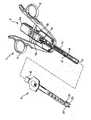
クリップマガジンの構造
図1および図4によるクリップマガジン4の各々はシャフト部分を有し、シャフト部分は、その寸法に関してハンドグリップ2のU字型シャフト10に挿入することができ、同時に、マガジン4のクリップ受入部分(クリップ収納手段)を形成する。クリップマガジン4をハンドグリップ2に着脱可能に締結/拘束する目的で、実質的にシャフト状のクリップマガジン4は取付装置16を備え、取付装置16は、シャフト部分の近位端に設けられ、ハンドグリップ2のシャフト10に(部分的に)挿入されるクリップマガジン4をハンドグリップ2に着脱可能に係止/拘束するために、ハンドグリップ2のロック(保持装置)18と協働する。Structure of Clip Magazine Each of Clip Magazine 4 according to FIGS. 1 and 4 has a shaft portion, which can be inserted into the
図3および図4によれば、クリップマガジン4のシャフト部分の遠位端部分には、圧着器具22が設けられており、圧着器具22は、ハンドグリップ2と組み立てられたときにハンドグリップ2のシャフト10の遠位シャフト端部から突出する圧着ヘッド(ジョー部)20を備えている。圧着ヘッド20(以下、ジョー部とも呼ぶ)は、クリップアプリケータ1の遠位端部にクリップアプリケータ1の圧着器具/圧着機構22を合わせて形成するために、U字型スライダとして形成されるハンドグリップ2の閉鎖装置12と協働するように配置されている。 According to FIGS. 3 and 4, a crimping
U字型スライダとして形成された閉鎖装置12と協働するために、ジョー部20は(その長手方向に示すように)その左外側および右外側に、各々1つの(制御)案内手段24および26が設けられている。案内手段24,26および閉鎖装置12は、ジョー部20の開閉移動を合わせて規定するように各々が配置されている。ここでは、クリップマガジンおよび/またはクリップタイプに従って圧着ヘッド20に相対的に大きいまたは相対的に小さいジョー開口部が必要であるため、ジョー部20の案内手段24,26の位置および幾何学的形状は、特に、選択されたクリップマガジンおよび/または適用されるクリップタイプに応じて、複数のクリップマガジンの中の異なるクリップマガジンに対して個別に規定することができまたは規定されている。 To cooperate with the closing
U字型スライダとして形成された閉鎖装置12が、ハンドグリップシャフト10におけるその長手方向移動中にジョー部20の案内手段24,26を少なくとも部分的に外部から囲み、それにより、U字型閉鎖装置12の2つの内面(図2には示さず)が、案内手段24,26と接触し、そのため、ジョー部20の開閉移動を規定または制御する場合に、圧着ヘッド/ジョー部20の開閉移動は発生する。このために、ジョー部20および閉鎖装置12は、各々、2つのハンドルレバー6,8が手動で操作された(圧縮された)場合に、U字型スライダとして形成された閉鎖装置12が、シャフト10の長手方向に保持部(ボルト)14によって固定されるジョー部20を囲むように配置または構成されている。これは、閉鎖装置12が(ハンドグリップ2の先に示したコンロッド56,58によるハンドルレバー6,8の操作時に)、閉鎖装置12がジョー部20の案内手段24,26を取り囲み、したがって、ジョー部20を強制的に閉鎖移動させるまで、クリップアプリケータ1の遠位方向において長手方向に、遠位方向にはるかに前方に移動するかまたは押されることを意味する。案内手段24,26の位置および/または形状によって規定されるかまたは制御される閉鎖装置12のこの移動により、ジョー部20は閉鎖され、ハンドルレバー6,8の操作の後、またはハンドルレバー6,8を解除することにより、再び開放される。開放移動は、U字型スライダとして形成された閉鎖装置12の(遠位から見た)後方移動によってもたらされる。 The closing
図3は、クリップマガジン4の底面斜視図であり、例示のため部分的に分解されているか、またはより例示的な説明のためにそこから個別の構成部品が取り除かれている。 FIG. 3 is a bottom perspective view of the clip magazine 4, which is either partially disassembled for illustration purposes or individual components removed from it for a more exemplary description.
図3において、圧着器具22は、実質的にフォークのように形成され、互いに平行な2つの分岐28および30を備えていることが分かる。遠位方向を指す圧着器具22の自由端において、圧着器具には2つのジョー部要素32および34が一体的に形成されており、そこに、上述した上記案内手段24,26が配置/形成され、それらがジョー部(圧着ヘッド)20を構成している。圧着器具22の近位端には、ハンドグリップ2の保持部(ボルト)14と噛合い協働するための締結開口部としての凹部36が設けられていることも分かる。この例示的な実施形態では、(シャフト10において適所にスナップ式に嵌められる)圧着器具22を、それがクリップマガジン4の長手方向にかつハンドグリップ部2のシャフト10の長手方向に移動することができないように、シャフト10に確実に固定するために、凹部36は、組み立てられた状態でハンドグリップ2の保持部14が係合する細長い孔として実施される。言い換えれば、圧着器具22の長手方向位置、したがってジョー部20の長手方向位置は、凹部36の保持部14との協働によって規定され、それにより、圧着器具22は、ハンドグリップ2のシャフト10に対してもクリップマガジン4の他の構成部品に対しても移動することができない。 In FIG. 3, it can be seen that the crimping
図3に示すクリップマガジン4はまた、分離されたクリップを受け入れかつ供給する(すなわち、搬送する)ためのクリップ前進バーの形態のクリップ前進手段38を備えている。クリップ前進手段38は、ジョー部20と協働するように配置され、クリップマガジン4の長手方向においてまたはハンドグリップ2のシャフト10の長手方向においてジョー部20に対してシフト可能に支持される。これは、送りユニット38が、クリップマガジン4から個別クリップを受け取り、シャフト10の遠位長手方向において前方へそれらを搬送する機能を有することを意味する。この目的で、クリップ前進手段38には、その遠位端に、個別クリップを受け取りかつ供給または搬送することができるクリップ舌状部(clip tongue)40が設けられている。 The clip magazine 4 shown in FIG. 3 also includes a clip advance means 38 in the form of a clip advance bar for receiving and supplying (ie, transporting) the separated clips. The
クリップマガジン4から個別クリップを受け取るために、個別クリップがジョー部要素32、34に収納されるように(遠位から見て)その後方に配置されるため、クリップ前進手段38の(遠位から見た)後方移動が必要である。この理由で、次に受け取られかつジョー部20に向かってシャフト10の長手方向において前方に送られまたは搬送されるべきクリップの(遠位から見て)厳密に後方に配置されるように、クリップ前進手段38は後方移動を行わなければならない。一方、クリップ前進手段38によって受け取られたクリップを供給または搬送するために、受け取られたクリップをジョー部20に向かって、すなわちそのジョー部要素32、34の間の圧着器具22の分岐28、30に沿って移動させる(近位から見た)前方移動が必要である。 In order to receive the individual clips from the clip magazine 4, the individual clips are arranged behind the
クリップ前進手段38のこれらの2つの長手方向移動を簡単な方法で、すなわち(近位から見て)ジョー部20に向かって前方にかつ(近位から見て)クリップ受取部分(クリップ収納手段)に向かって後方に制限するために、クリップ前進手段38は、その長手方向において互いに間隔を開けて配置された2つの制限止め具42および44を備えている。制限止め具42、44は、それらが各々、クリップ前進手段38に対する長手方向位置が凹部36と係合する保持部14によって画定される圧着器具22と接触することができるような、形状および寸法である。これは、状況に応じて圧着器具22にぶつかる制限止め具42、44が、両長手方向においてクリップ前進手段38の長手方向移動を制限することを意味する。 These two longitudinal movements of the clip advancing means 38 are in a simple way, i.e., forward (as viewed from the proximal) toward the
例示的な実施形態では、制限止め具42、44は、クリップ前進手段38との単一部品で打抜き部/曲げ部として実施される。2つの制限止め具42、44の間の長手方向における距離は、より詳細に後述するように、クリップ舌状部40が(クリップ前進手段38の(近位から見た)後方移動時、すなわち、クリップ送り手段38のクリップ受取移動の過程において)、クリップマガジン4から厳密に1つのクリップを取得するようなサイズであり、またはそのように選択されかつ規定される。図3は、近位の、すなわちクリップ前進手段に見られるような後方制限止め具44が、圧着器具22と静止して接触している状況または位置にある、クリップ前進手段38を示す。したがって、図3によれば、クリップ前進手段38は、個別クリップ46が、クリップ前進手段38のクリップ舌状部40によって、ジョー部20の遠位端に向かって、すなわち圧着器具22内に搬送されており、または圧着器具22内に配置されている状況又は位置で示されている。 In an exemplary embodiment, the limiting
図3に示すクリップ前進手段38の位置は、挿入されたクリップを圧着するジョー部20のジョー32、34が閉鎖することができる位置では(まだ)ないことが明らかである。ジョー部要素32、34を閉鎖させるために、クリップ前進手段38の後方移動が予め必要であり、それにより、クリップ前進手段38は、図示する位置においてジョー部要素32、34の間に完全に留まらない。 It is clear that the position of the clip advancing means 38 shown in FIG. 3 is not (yet) at a position where the
部分的に分解された状態でクリップマガジン4の一部の底面斜視図を示す図4において、クリップ前進手段38は、個別クリップ46をジョー部20(圧着器具22)に向かって供給しまたは進めるように、クリップマガジン4のクリップ収納部分48から個別クリップ46を受け取ることができる、別の状況/位置で示されている。クリップ収納部分48は、(遠位から見て)ジョー部要素32、34の後方に配置されており、それにより、個別クリップ46をジョー部要素32、34の間に搬送するために、個別クリップ46は、(遠位から見て)前方方向に供給または搬送されなければならないことが分かる。 In FIG. 4, which shows a perspective view of a part of the bottom surface of the clip magazine 4 in a partially disassembled state, the clip advancing means 38 supplies or advances the
さらに、図4では、図示するクリップ受入位置にあるクリップ前進手段38は、遠位制限止め具42、すなわち、クリップ前進手段の前方の止め具42により圧着器具22に当接しており、それにより、クリップ受入移動がこの移動方向において制限されていることが分かる。クリップマガジン4に応じて寸法が決められかつそれに対応して規定される制限止め具42の位置決めにより、クリップマガジン4のクリップ収納手段48から常に単一のクリップ46のみが取得され、続くクリップ前進方向におけるクリップ送り移動において、圧着器具22の遠位端に向かって、すなわちジョー部要素32、34間にかつジョー部20内に搬送されることが確実になる。 Further, in FIG. 4, the clip advancing means 38 at the illustrated clip receiving position is in contact with the crimping
部分的に分解された状態でクリップアプリケータ1の側面斜視図を示す図5では、クリップアプリケータ1のハンドグリップ2は、摺動クラッチ52を含む一体化された過負荷保護手段50を備えていることを見ることができる。(摺動クラッチ52を含む)過負荷保護手段50は、ハンドグリップ2の機械的部品および/またはクリップマガジン4の機械的部品あるいはハウジング部品、または制限止め具42自体あるいはジョー部20が、前方制限止め具42が圧着器具22にぶつかった場合に術者の過剰に高い作動力によって損傷を受けるのを防止する。複数のクリップマガジンの中の異なるクリップマガジンに対するクリップマガジン4の制限止め具42、44の間の距離は、異なるように配置されるかまたは規定されるため、過負荷保護手段50はさらに、汎用ハンドグリップ2が、それぞれのハンドグリップ2および/またはそれぞれのクリップマガジン4の機械的部品または構成部品に、過剰に高い手動の作動力によって損傷を与えることなく、複数のクリップマガジンの中のいくつかのマガジンと協働することができる。 In FIG. 5, which shows a side perspective view of the clip applicator 1 in a partially disassembled state, the hand grip 2 of the clip applicator 1 includes an integrated overload protection means 50 including a sliding clutch 52. You can see that you are. In the overload protection means 50 (including the sliding clutch 52), the mechanical parts of the hand grip 2 and / or the mechanical parts or housing parts of the clip magazine 4, or the limiting
クリップアプリケータ1の動作および実際の使用は、以下に記載するように進行することができる。 The operation and actual use of the clip applicator 1 can proceed as described below.
図2は、組み立てられた、すなわち、クリップマガジン4が取付装置16および保持装置18の協働によって締結される作動状態にある、クリップアプリケータ1を側面斜視図で示す。 FIG. 2 is a side perspective view of the clip applicator 1, which is assembled, that is, in an operating state in which the clip magazine 4 is fastened by the cooperation of the
(必要に応じて選択された)クリップマガジン4を汎用ハンドグリップ2に取り付けることによってクリップアプリケータ1を組み立てると、クリップアプリケータ1は作動状態にある。これは、この状態で、クリップマガジン4がハンドグリップシャフト10に挿入され、ロック18によって拘束されることを意味する。 When the clip applicator 1 is assembled by attaching the clip magazine 4 (selected as needed) to the general purpose handgrip 2, the clip applicator 1 is in an operating state. This means that in this state, the clip magazine 4 is inserted into the
ハンドグリップ2の2つのハンドルレバー6および8の手動操作により、U字型スライダとして実現された閉鎖装置12が遠位方向において長手方向に変位するように、ハンドグリップ2の内部機械的作動システム54が起動する。閉鎖装置12のこの長手方向変位により、閉鎖装置12は、ジョー部20の案内手段24、26の上で押され、それにより、そのジョー部要素32、34は互いに向かって(すなわち、内側方向に)加圧され、したがって、圧着器具22が閉鎖される。 The internal
一方で、ハンドグリップ2の内部機械的作動システム54はまた同時に、前方制限止め具42が固定された圧着器具22にぶつかり、場合によっては、過負荷保護手段50の摺動クラッチ52がトリガされるまで、クリップ前進手段38が、閉鎖装置12の移動方向に対して反対の長手方向移動で(近位方向に)シフトするように、駆動される。ハンドグリップ2の内部機械的作動システム54は、ジョー部要素32、34が再び、閉鎖装置12を押し戻すことによって互いから間隔が開けられ、これにより、圧着器具22が再度開放されるまで、クリップ前進手段38をこの位置で保持する。圧着器具22が開放されることにより、再びジョー部要素32、34の間に隙間が生成され、クリップ前進手段38は、内部機械的作動システム54によって(自動的に)解放され、次のクリップが、ジョー部要素32、34の間のクリップ舌状部40のばね式に支持された前方移動によって搬送され得る。 On the other hand, the internal
要約すると、汎用ハンドグリップと、一体化された圧着ヘッドを有する個別クリップマガジンとを備え、個別クリップマガジンを汎用ハンドグリップに着脱可能に締結することができる、外科用クリップアプリケータが開示される。汎用ハンドグリップとそれに締結された個別クリップマガジンとは、クリップマガジンのクリップ受入部分から圧着ヘッドに向かう個別クリップのクリップ搬送用の送り経路を形成するために相互作用し、送り経路は、規定されるかまたは作動に対して個別に利用可能である。本発明によれば、個別クリップマガジンは、必要に応じて異なるクリップタイプに対して複数のクリップマガジンから選択することができ、クリップマガジンには、適用されるクリップタイプに応じて設計された一体化されたコード化機構を備え、コード化機構は、汎用ハンドグリップと相互作用して少なくともそれぞれのクリップタイプに適合された送り経路を規定する。 In summary, a surgical clip applicator comprising a general purpose handgrip and an individual clip magazine with an integrated crimping head, capable of detachably fastening the individual clip magazine to the general purpose handgrip, is disclosed. The general-purpose handgrip and the individual clip magazine fastened to it interact to form a feed path for clip transfer of the individual clip from the clip receiving portion of the clip magazine to the crimping head, and the feed path is defined. Or available individually for operation. According to the present invention, the individual clip magazines can be selected from a plurality of clip magazines for different clip types as needed, and the clip magazines are integrated designed according to the clip type applied. With a coded coding mechanism, the coding mechanism interacts with a general purpose handgrip to define a feed path adapted to at least each clip type.
Claims (12)
Translated fromJapanese別個のユニットとして形成されている個別クリップマガジン(4)と、
複数の異なるクリップマガジンから任意に選択される前記個別クリップマガジン(4)を、取り外し可能に取り付けるまたは締結することができる汎用ハンドグリップ(2)と、を備え、
前記個別クリップマガジン(4)は、
その遠位端部分にある圧着ヘッド/圧着器具(20、22)と、
前記圧着ヘッド/圧着器具(20、22)に対して近位に設けられたクリップ受取部分(48)と、
個別クリップを前記クリップ受取部分(48)から個別送り経路を介して前記圧着ヘッド/圧着器具に向かって搬送するためのクリップ前進装置(38)と、
前記個別送り経路を規定し、それによって前記クリップ前進装置(38)の搬送運動を制限する2つの制限止め具(42、44)を備えるコード化機構(20、24、26、38、42、44)であって、前記制限止め具(42、44)は、前記個別クリップマガジンに収容される前記クリップのタイプに応じて形成され、かつ、配置される、前記コード化機構と、
前記汎用ハンドグリップ(2)に前記クリップマガジン(4)を取り外し可能に係止又は拘束するように適合された、前記個別クリップマガジン(4)の近位端部分と、を備え、
前記汎用ハンドグリップ(2)は、一体化された力伝達ギア(54)を備えており、
前記一体化された力伝達ギア(54)は、
作動/入力部としての少なくとも1つの手で把持可能なハンドル(6、8)と、
前記個別クリップマガジン(4)に対する作動/搬送部としての結合要素(18)であって、前記個別クリップマガジン(4)が、前記個別クリップマガジン(4)の前記近位端部分によって前記汎用ハンドグリップ(2)に取り付けられて係止/拘束されたときに、前記クリップ前進装置(38)と相互接続されるように適合された前記結合要素(18)と、
前記クリップ前進装置(38)の搬送運動が、前記2つの制限止め具(42、44)の一方によって制限されているときに、前記力伝達ギア(54)内の前記少なくとも1つの手で把持可能なハンドルと前記結合要素(18)との間の力伝達を遮断するための摺動クラッチ(52)の形態である過負荷保護手段(50)と、を備える、
外科用クリップアプリケータ(1)。Surgical clip applicator (1)
An individual clip magazine (4) formed as a separate unit, and
The individual clip magazine (4), which is arbitrarily selected from a plurality of different clip magazines, is provided with a general-purpose hand grip (2) which can be detachably attached or fastened.
The individual clip magazine (4)
The crimping head / crimping device (20, 22) at its distal end,
A clip receiving portion (48) provided proximal to the crimping head / crimping device (20, 22) and
A clip advancing device (38) for transporting an individual clip from the clip receiving portion (48) toward the crimping head / crimping tool via an individual feed path, and
A coding mechanism (20, 24, 26, 38, 42, 44) comprising two limiting stoppers (42, 44) that define the individual feed path and thereby limit the transport movement of the clip advance device (38). ), The limiting stoppers (42, 44) are formed and arranged according to the type of the clip housed in the individual clip magazine, and the coding mechanism.
The general purpose handgrip (2) is provided with a proximal end portion of the individual clip magazine (4) adapted to detachably lock or constrain the clip magazine (4).
The general-purpose hand grip (2) includes an integrated force transmission gear (54).
The integrated force transmission gear (54)
Handles (6, 8) that can be gripped by at least one hand as an actuating / input section,
A coupling element (18) as an actuating / conveying section to the individual clip magazine (4), wherein the individual clip magazine (4) is the general purpose handgrip by the proximal end portion of the individual clip magazine (4). With the coupling element (18) adapted to be interconnected with the clip advance device (38) when attached to (2) and locked / constrained.
When the transport movement of the clip advance device (38) is restricted by one of the two limiting stoppers (42, 44), it can be gripped by the at least one hand in theforce transmission gear (54). The overload protection means (50), which is in the form of a sliding clutch (52) for blockingthe force transmission betweenthe handle and the coupling element (18), is provided.
Surgical clip applicator (1).
Applications Claiming Priority (2)
| Application Number | Priority Date | Filing Date | Title |
|---|---|---|---|
| DE102013106277.6 | 2013-06-17 | ||
| DE102013106277.6ADE102013106277A1 (en) | 2013-06-17 | 2013-06-17 | Surgical clip applicator |
Related Parent Applications (1)
| Application Number | Title | Priority Date | Filing Date |
|---|---|---|---|
| JP2016518484ADivisionJP2016523617A (en) | 2013-06-17 | 2014-06-12 | Surgical clip applicator |
Publications (2)
| Publication Number | Publication Date |
|---|---|
| JP2019130328A JP2019130328A (en) | 2019-08-08 |
| JP6771058B2true JP6771058B2 (en) | 2020-10-21 |
Family
ID=50981490
Family Applications (2)
| Application Number | Title | Priority Date | Filing Date |
|---|---|---|---|
| JP2016518484APendingJP2016523617A (en) | 2013-06-17 | 2014-06-12 | Surgical clip applicator |
| JP2019046238AActiveJP6771058B2 (en) | 2013-06-17 | 2019-03-13 | Surgical clip applicator |
Family Applications Before (1)
| Application Number | Title | Priority Date | Filing Date |
|---|---|---|---|
| JP2016518484APendingJP2016523617A (en) | 2013-06-17 | 2014-06-12 | Surgical clip applicator |
Country Status (7)
| Country | Link |
|---|---|
| US (1) | US10390830B2 (en) |
| EP (1) | EP3010425B1 (en) |
| JP (2) | JP2016523617A (en) |
| CN (1) | CN105555206B (en) |
| DE (1) | DE102013106277A1 (en) |
| ES (1) | ES2907256T3 (en) |
| WO (1) | WO2014202449A2 (en) |
Families Citing this family (391)
| Publication number | Priority date | Publication date | Assignee | Title |
|---|---|---|---|---|
| US9060770B2 (en) | 2003-05-20 | 2015-06-23 | Ethicon Endo-Surgery, Inc. | Robotically-driven surgical instrument with E-beam driver |
| US20070084897A1 (en) | 2003-05-20 | 2007-04-19 | Shelton Frederick E Iv | Articulating surgical stapling instrument incorporating a two-piece e-beam firing mechanism |
| US8215531B2 (en) | 2004-07-28 | 2012-07-10 | Ethicon Endo-Surgery, Inc. | Surgical stapling instrument having a medical substance dispenser |
| US11998198B2 (en) | 2004-07-28 | 2024-06-04 | Cilag Gmbh International | Surgical stapling instrument incorporating a two-piece E-beam firing mechanism |
| US11890012B2 (en) | 2004-07-28 | 2024-02-06 | Cilag Gmbh International | Staple cartridge comprising cartridge body and attached support |
| US9072535B2 (en) | 2011-05-27 | 2015-07-07 | Ethicon Endo-Surgery, Inc. | Surgical stapling instruments with rotatable staple deployment arrangements |
| US11246590B2 (en) | 2005-08-31 | 2022-02-15 | Cilag Gmbh International | Staple cartridge including staple drivers having different unfired heights |
| US9237891B2 (en) | 2005-08-31 | 2016-01-19 | Ethicon Endo-Surgery, Inc. | Robotically-controlled surgical stapling devices that produce formed staples having different lengths |
| US10159482B2 (en) | 2005-08-31 | 2018-12-25 | Ethicon Llc | Fastener cartridge assembly comprising a fixed anvil and different staple heights |
| US7669746B2 (en) | 2005-08-31 | 2010-03-02 | Ethicon Endo-Surgery, Inc. | Staple cartridges for forming staples having differing formed staple heights |
| US7934630B2 (en) | 2005-08-31 | 2011-05-03 | Ethicon Endo-Surgery, Inc. | Staple cartridges for forming staples having differing formed staple heights |
| US11484312B2 (en) | 2005-08-31 | 2022-11-01 | Cilag Gmbh International | Staple cartridge comprising a staple driver arrangement |
| US20070106317A1 (en) | 2005-11-09 | 2007-05-10 | Shelton Frederick E Iv | Hydraulically and electrically actuated articulation joints for surgical instruments |
| US8186555B2 (en) | 2006-01-31 | 2012-05-29 | Ethicon Endo-Surgery, Inc. | Motor-driven surgical cutting and fastening instrument with mechanical closure system |
| US8708213B2 (en) | 2006-01-31 | 2014-04-29 | Ethicon Endo-Surgery, Inc. | Surgical instrument having a feedback system |
| US20120292367A1 (en) | 2006-01-31 | 2012-11-22 | Ethicon Endo-Surgery, Inc. | Robotically-controlled end effector |
| US11224427B2 (en) | 2006-01-31 | 2022-01-18 | Cilag Gmbh International | Surgical stapling system including a console and retraction assembly |
| US7753904B2 (en) | 2006-01-31 | 2010-07-13 | Ethicon Endo-Surgery, Inc. | Endoscopic surgical instrument with a handle that can articulate with respect to the shaft |
| US7845537B2 (en) | 2006-01-31 | 2010-12-07 | Ethicon Endo-Surgery, Inc. | Surgical instrument having recording capabilities |
| US11793518B2 (en) | 2006-01-31 | 2023-10-24 | Cilag Gmbh International | Powered surgical instruments with firing system lockout arrangements |
| US20110024477A1 (en) | 2009-02-06 | 2011-02-03 | Hall Steven G | Driven Surgical Stapler Improvements |
| US8820603B2 (en) | 2006-01-31 | 2014-09-02 | Ethicon Endo-Surgery, Inc. | Accessing data stored in a memory of a surgical instrument |
| US20110295295A1 (en) | 2006-01-31 | 2011-12-01 | Ethicon Endo-Surgery, Inc. | Robotically-controlled surgical instrument having recording capabilities |
| US11278279B2 (en) | 2006-01-31 | 2022-03-22 | Cilag Gmbh International | Surgical instrument assembly |
| US8992422B2 (en) | 2006-03-23 | 2015-03-31 | Ethicon Endo-Surgery, Inc. | Robotically-controlled endoscopic accessory channel |
| US8322455B2 (en) | 2006-06-27 | 2012-12-04 | Ethicon Endo-Surgery, Inc. | Manually driven surgical cutting and fastening instrument |
| US10568652B2 (en) | 2006-09-29 | 2020-02-25 | Ethicon Llc | Surgical staples having attached drivers of different heights and stapling instruments for deploying the same |
| US11980366B2 (en) | 2006-10-03 | 2024-05-14 | Cilag Gmbh International | Surgical instrument |
| US8632535B2 (en) | 2007-01-10 | 2014-01-21 | Ethicon Endo-Surgery, Inc. | Interlock and surgical instrument including same |
| US8684253B2 (en) | 2007-01-10 | 2014-04-01 | Ethicon Endo-Surgery, Inc. | Surgical instrument with wireless communication between a control unit of a robotic system and remote sensor |
| US11291441B2 (en) | 2007-01-10 | 2022-04-05 | Cilag Gmbh International | Surgical instrument with wireless communication between control unit and remote sensor |
| US20080169333A1 (en) | 2007-01-11 | 2008-07-17 | Shelton Frederick E | Surgical stapler end effector with tapered distal end |
| US11039836B2 (en) | 2007-01-11 | 2021-06-22 | Cilag Gmbh International | Staple cartridge for use with a surgical stapling instrument |
| US7673782B2 (en) | 2007-03-15 | 2010-03-09 | Ethicon Endo-Surgery, Inc. | Surgical stapling instrument having a releasable buttress material |
| US11564682B2 (en) | 2007-06-04 | 2023-01-31 | Cilag Gmbh International | Surgical stapler device |
| US8931682B2 (en) | 2007-06-04 | 2015-01-13 | Ethicon Endo-Surgery, Inc. | Robotically-controlled shaft based rotary drive systems for surgical instruments |
| US7753245B2 (en) | 2007-06-22 | 2010-07-13 | Ethicon Endo-Surgery, Inc. | Surgical stapling instruments |
| US11849941B2 (en) | 2007-06-29 | 2023-12-26 | Cilag Gmbh International | Staple cartridge having staple cavities extending at a transverse angle relative to a longitudinal cartridge axis |
| US9179912B2 (en) | 2008-02-14 | 2015-11-10 | Ethicon Endo-Surgery, Inc. | Robotically-controlled motorized surgical cutting and fastening instrument |
| US7866527B2 (en) | 2008-02-14 | 2011-01-11 | Ethicon Endo-Surgery, Inc. | Surgical stapling apparatus with interlockable firing system |
| US11986183B2 (en) | 2008-02-14 | 2024-05-21 | Cilag Gmbh International | Surgical cutting and fastening instrument comprising a plurality of sensors to measure an electrical parameter |
| US8636736B2 (en) | 2008-02-14 | 2014-01-28 | Ethicon Endo-Surgery, Inc. | Motorized surgical cutting and fastening instrument |
| US7819298B2 (en) | 2008-02-14 | 2010-10-26 | Ethicon Endo-Surgery, Inc. | Surgical stapling apparatus with control features operable with one hand |
| US8573465B2 (en) | 2008-02-14 | 2013-11-05 | Ethicon Endo-Surgery, Inc. | Robotically-controlled surgical end effector system with rotary actuated closure systems |
| US8758391B2 (en) | 2008-02-14 | 2014-06-24 | Ethicon Endo-Surgery, Inc. | Interchangeable tools for surgical instruments |
| JP5410110B2 (en) | 2008-02-14 | 2014-02-05 | エシコン・エンド−サージェリィ・インコーポレイテッド | Surgical cutting / fixing instrument with RF electrode |
| US9585657B2 (en) | 2008-02-15 | 2017-03-07 | Ethicon Endo-Surgery, Llc | Actuator for releasing a layer of material from a surgical end effector |
| US9005230B2 (en) | 2008-09-23 | 2015-04-14 | Ethicon Endo-Surgery, Inc. | Motorized surgical instrument |
| US9386983B2 (en) | 2008-09-23 | 2016-07-12 | Ethicon Endo-Surgery, Llc | Robotically-controlled motorized surgical instrument |
| US11648005B2 (en) | 2008-09-23 | 2023-05-16 | Cilag Gmbh International | Robotically-controlled motorized surgical instrument with an end effector |
| US8210411B2 (en) | 2008-09-23 | 2012-07-03 | Ethicon Endo-Surgery, Inc. | Motor-driven surgical cutting instrument |
| US8608045B2 (en) | 2008-10-10 | 2013-12-17 | Ethicon Endo-Sugery, Inc. | Powered surgical cutting and stapling apparatus with manually retractable firing system |
| US8517239B2 (en) | 2009-02-05 | 2013-08-27 | Ethicon Endo-Surgery, Inc. | Surgical stapling instrument comprising a magnetic element driver |
| RU2525225C2 (en) | 2009-02-06 | 2014-08-10 | Этикон Эндо-Серджери, Инк. | Improvement of drive surgical suturing instrument |
| US8851354B2 (en) | 2009-12-24 | 2014-10-07 | Ethicon Endo-Surgery, Inc. | Surgical cutting instrument that analyzes tissue thickness |
| US8220688B2 (en) | 2009-12-24 | 2012-07-17 | Ethicon Endo-Surgery, Inc. | Motor-driven surgical cutting instrument with electric actuator directional control assembly |
| US8783543B2 (en) | 2010-07-30 | 2014-07-22 | Ethicon Endo-Surgery, Inc. | Tissue acquisition arrangements and methods for surgical stapling devices |
| US11925354B2 (en) | 2010-09-30 | 2024-03-12 | Cilag Gmbh International | Staple cartridge comprising staples positioned within a compressible portion thereof |
| US9386988B2 (en) | 2010-09-30 | 2016-07-12 | Ethicon End-Surgery, LLC | Retainer assembly including a tissue thickness compensator |
| US11298125B2 (en) | 2010-09-30 | 2022-04-12 | Cilag Gmbh International | Tissue stapler having a thickness compensator |
| US9788834B2 (en) | 2010-09-30 | 2017-10-17 | Ethicon Llc | Layer comprising deployable attachment members |
| US10945731B2 (en) | 2010-09-30 | 2021-03-16 | Ethicon Llc | Tissue thickness compensator comprising controlled release and expansion |
| US11812965B2 (en) | 2010-09-30 | 2023-11-14 | Cilag Gmbh International | Layer of material for a surgical end effector |
| US9629814B2 (en) | 2010-09-30 | 2017-04-25 | Ethicon Endo-Surgery, Llc | Tissue thickness compensator configured to redistribute compressive forces |
| US9016542B2 (en) | 2010-09-30 | 2015-04-28 | Ethicon Endo-Surgery, Inc. | Staple cartridge comprising compressible distortion resistant components |
| US9351730B2 (en) | 2011-04-29 | 2016-05-31 | Ethicon Endo-Surgery, Llc | Tissue thickness compensator comprising channels |
| US12213666B2 (en) | 2010-09-30 | 2025-02-04 | Cilag Gmbh International | Tissue thickness compensator comprising layers |
| US8695866B2 (en) | 2010-10-01 | 2014-04-15 | Ethicon Endo-Surgery, Inc. | Surgical instrument having a power control circuit |
| AU2012250197B2 (en) | 2011-04-29 | 2017-08-10 | Ethicon Endo-Surgery, Inc. | Staple cartridge comprising staples positioned within a compressible portion thereof |
| US11207064B2 (en) | 2011-05-27 | 2021-12-28 | Cilag Gmbh International | Automated end effector component reloading system for use with a robotic system |
| US9044230B2 (en) | 2012-02-13 | 2015-06-02 | Ethicon Endo-Surgery, Inc. | Surgical cutting and fastening instrument with apparatus for determining cartridge and firing motion status |
| MX358135B (en) | 2012-03-28 | 2018-08-06 | Ethicon Endo Surgery Inc | Tissue thickness compensator comprising a plurality of layers. |
| JP6224070B2 (en) | 2012-03-28 | 2017-11-01 | エシコン・エンド−サージェリィ・インコーポレイテッドEthicon Endo−Surgery,Inc. | Retainer assembly including tissue thickness compensator |
| BR112014024098B1 (en) | 2012-03-28 | 2021-05-25 | Ethicon Endo-Surgery, Inc. | staple cartridge |
| US9101358B2 (en) | 2012-06-15 | 2015-08-11 | Ethicon Endo-Surgery, Inc. | Articulatable surgical instrument comprising a firing drive |
| BR112014032776B1 (en) | 2012-06-28 | 2021-09-08 | Ethicon Endo-Surgery, Inc | SURGICAL INSTRUMENT SYSTEM AND SURGICAL KIT FOR USE WITH A SURGICAL INSTRUMENT SYSTEM |
| US12383267B2 (en) | 2012-06-28 | 2025-08-12 | Cilag Gmbh International | Robotically powered surgical device with manually-actuatable reversing system |
| US9408606B2 (en) | 2012-06-28 | 2016-08-09 | Ethicon Endo-Surgery, Llc | Robotically powered surgical device with manually-actuatable reversing system |
| US11278284B2 (en) | 2012-06-28 | 2022-03-22 | Cilag Gmbh International | Rotary drive arrangements for surgical instruments |
| US9282974B2 (en) | 2012-06-28 | 2016-03-15 | Ethicon Endo-Surgery, Llc | Empty clip cartridge lockout |
| US20140001231A1 (en) | 2012-06-28 | 2014-01-02 | Ethicon Endo-Surgery, Inc. | Firing system lockout arrangements for surgical instruments |
| US9289256B2 (en) | 2012-06-28 | 2016-03-22 | Ethicon Endo-Surgery, Llc | Surgical end effectors having angled tissue-contacting surfaces |
| JP6290201B2 (en) | 2012-06-28 | 2018-03-07 | エシコン・エンド−サージェリィ・インコーポレイテッドEthicon Endo−Surgery,Inc. | Lockout for empty clip cartridge |
| BR112015021082B1 (en) | 2013-03-01 | 2022-05-10 | Ethicon Endo-Surgery, Inc | surgical instrument |
| RU2672520C2 (en) | 2013-03-01 | 2018-11-15 | Этикон Эндо-Серджери, Инк. | Hingedly turnable surgical instruments with conducting ways for signal transfer |
| US9629629B2 (en) | 2013-03-14 | 2017-04-25 | Ethicon Endo-Surgey, LLC | Control systems for surgical instruments |
| US9808244B2 (en) | 2013-03-14 | 2017-11-07 | Ethicon Llc | Sensor arrangements for absolute positioning system for surgical instruments |
| US9826976B2 (en) | 2013-04-16 | 2017-11-28 | Ethicon Llc | Motor driven surgical instruments with lockable dual drive shafts |
| BR112015026109B1 (en) | 2013-04-16 | 2022-02-22 | Ethicon Endo-Surgery, Inc | surgical instrument |
| US9775609B2 (en) | 2013-08-23 | 2017-10-03 | Ethicon Llc | Tamper proof circuit for surgical instrument battery pack |
| MX369362B (en) | 2013-08-23 | 2019-11-06 | Ethicon Endo Surgery Llc | Firing member retraction devices for powered surgical instruments. |
| US9962161B2 (en) | 2014-02-12 | 2018-05-08 | Ethicon Llc | Deliverable surgical instrument |
| US20150272580A1 (en) | 2014-03-26 | 2015-10-01 | Ethicon Endo-Surgery, Inc. | Verification of number of battery exchanges/procedure count |
| US12232723B2 (en) | 2014-03-26 | 2025-02-25 | Cilag Gmbh International | Systems and methods for controlling a segmented circuit |
| BR112016021943B1 (en) | 2014-03-26 | 2022-06-14 | Ethicon Endo-Surgery, Llc | SURGICAL INSTRUMENT FOR USE BY AN OPERATOR IN A SURGICAL PROCEDURE |
| US10013049B2 (en) | 2014-03-26 | 2018-07-03 | Ethicon Llc | Power management through sleep options of segmented circuit and wake up control |
| US10004497B2 (en) | 2014-03-26 | 2018-06-26 | Ethicon Llc | Interface systems for use with surgical instruments |
| CN106456159B (en) | 2014-04-16 | 2019-03-08 | 伊西康内外科有限责任公司 | Fastener Cartridge Assembly and Nail Retainer Cover Arrangement |
| CN106456176B (en) | 2014-04-16 | 2019-06-28 | 伊西康内外科有限责任公司 | Fastener Cartridge Including Extensions With Different Configurations |
| US20150297225A1 (en) | 2014-04-16 | 2015-10-22 | Ethicon Endo-Surgery, Inc. | Fastener cartridges including extensions having different configurations |
| BR112016023825B1 (en) | 2014-04-16 | 2022-08-02 | Ethicon Endo-Surgery, Llc | STAPLE CARTRIDGE FOR USE WITH A SURGICAL STAPLER AND STAPLE CARTRIDGE FOR USE WITH A SURGICAL INSTRUMENT |
| US10470768B2 (en) | 2014-04-16 | 2019-11-12 | Ethicon Llc | Fastener cartridge including a layer attached thereto |
| US10327764B2 (en) | 2014-09-26 | 2019-06-25 | Ethicon Llc | Method for creating a flexible staple line |
| BR112017004361B1 (en) | 2014-09-05 | 2023-04-11 | Ethicon Llc | ELECTRONIC SYSTEM FOR A SURGICAL INSTRUMENT |
| US11311294B2 (en) | 2014-09-05 | 2022-04-26 | Cilag Gmbh International | Powered medical device including measurement of closure state of jaws |
| US10135242B2 (en) | 2014-09-05 | 2018-11-20 | Ethicon Llc | Smart cartridge wake up operation and data retention |
| US10105142B2 (en) | 2014-09-18 | 2018-10-23 | Ethicon Llc | Surgical stapler with plurality of cutting elements |
| US11523821B2 (en) | 2014-09-26 | 2022-12-13 | Cilag Gmbh International | Method for creating a flexible staple line |
| CN107427300B (en) | 2014-09-26 | 2020-12-04 | 伊西康有限责任公司 | Surgical suture buttresses and auxiliary materials |
| US10076325B2 (en) | 2014-10-13 | 2018-09-18 | Ethicon Llc | Surgical stapling apparatus comprising a tissue stop |
| US9924944B2 (en) | 2014-10-16 | 2018-03-27 | Ethicon Llc | Staple cartridge comprising an adjunct material |
| US10517594B2 (en) | 2014-10-29 | 2019-12-31 | Ethicon Llc | Cartridge assemblies for surgical staplers |
| US11141153B2 (en) | 2014-10-29 | 2021-10-12 | Cilag Gmbh International | Staple cartridges comprising driver arrangements |
| US9844376B2 (en) | 2014-11-06 | 2017-12-19 | Ethicon Llc | Staple cartridge comprising a releasable adjunct material |
| US10736636B2 (en) | 2014-12-10 | 2020-08-11 | Ethicon Llc | Articulatable surgical instrument system |
| US9844375B2 (en) | 2014-12-18 | 2017-12-19 | Ethicon Llc | Drive arrangements for articulatable surgical instruments |
| MX389118B (en) | 2014-12-18 | 2025-03-20 | Ethicon Llc | SURGICAL INSTRUMENT WITH AN ANVIL THAT CAN BE SELECTIVELY MOVED ON A DISCRETE, NON-MOBILE AXIS RELATIVE TO A STAPLE CARTRIDGE. |
| US9844374B2 (en) | 2014-12-18 | 2017-12-19 | Ethicon Llc | Surgical instrument systems comprising an articulatable end effector and means for adjusting the firing stroke of a firing member |
| US9943309B2 (en) | 2014-12-18 | 2018-04-17 | Ethicon Llc | Surgical instruments with articulatable end effectors and movable firing beam support arrangements |
| US10085748B2 (en) | 2014-12-18 | 2018-10-02 | Ethicon Llc | Locking arrangements for detachable shaft assemblies with articulatable surgical end effectors |
| US9987000B2 (en) | 2014-12-18 | 2018-06-05 | Ethicon Llc | Surgical instrument assembly comprising a flexible articulation system |
| US11154301B2 (en) | 2015-02-27 | 2021-10-26 | Cilag Gmbh International | Modular stapling assembly |
| US10441279B2 (en) | 2015-03-06 | 2019-10-15 | Ethicon Llc | Multiple level thresholds to modify operation of powered surgical instruments |
| US10687806B2 (en) | 2015-03-06 | 2020-06-23 | Ethicon Llc | Adaptive tissue compression techniques to adjust closure rates for multiple tissue types |
| US10548504B2 (en) | 2015-03-06 | 2020-02-04 | Ethicon Llc | Overlaid multi sensor radio frequency (RF) electrode system to measure tissue compression |
| US9993248B2 (en) | 2015-03-06 | 2018-06-12 | Ethicon Endo-Surgery, Llc | Smart sensors with local signal processing |
| JP2020121162A (en) | 2015-03-06 | 2020-08-13 | エシコン エルエルシーEthicon LLC | Time dependent evaluation of sensor data to determine stability element, creep element and viscoelastic element of measurement |
| US10245033B2 (en) | 2015-03-06 | 2019-04-02 | Ethicon Llc | Surgical instrument comprising a lockable battery housing |
| US10617412B2 (en) | 2015-03-06 | 2020-04-14 | Ethicon Llc | System for detecting the mis-insertion of a staple cartridge into a surgical stapler |
| US9901342B2 (en) | 2015-03-06 | 2018-02-27 | Ethicon Endo-Surgery, Llc | Signal and power communication system positioned on a rotatable shaft |
| US10433844B2 (en) | 2015-03-31 | 2019-10-08 | Ethicon Llc | Surgical instrument with selectively disengageable threaded drive systems |
| US10835249B2 (en) | 2015-08-17 | 2020-11-17 | Ethicon Llc | Implantable layers for a surgical instrument |
| US10105139B2 (en) | 2015-09-23 | 2018-10-23 | Ethicon Llc | Surgical stapler having downstream current-based motor control |
| US10238386B2 (en) | 2015-09-23 | 2019-03-26 | Ethicon Llc | Surgical stapler having motor control based on an electrical parameter related to a motor current |
| US10299878B2 (en) | 2015-09-25 | 2019-05-28 | Ethicon Llc | Implantable adjunct systems for determining adjunct skew |
| US11890015B2 (en) | 2015-09-30 | 2024-02-06 | Cilag Gmbh International | Compressible adjunct with crossing spacer fibers |
| US10980539B2 (en) | 2015-09-30 | 2021-04-20 | Ethicon Llc | Implantable adjunct comprising bonded layers |
| US10433846B2 (en) | 2015-09-30 | 2019-10-08 | Ethicon Llc | Compressible adjunct with crossing spacer fibers |
| US10478188B2 (en) | 2015-09-30 | 2019-11-19 | Ethicon Llc | Implantable layer comprising a constricted configuration |
| US10368865B2 (en) | 2015-12-30 | 2019-08-06 | Ethicon Llc | Mechanisms for compensating for drivetrain failure in powered surgical instruments |
| US10265068B2 (en) | 2015-12-30 | 2019-04-23 | Ethicon Llc | Surgical instruments with separable motors and motor control circuits |
| US10292704B2 (en) | 2015-12-30 | 2019-05-21 | Ethicon Llc | Mechanisms for compensating for battery pack failure in powered surgical instruments |
| BR112018016098B1 (en) | 2016-02-09 | 2023-02-23 | Ethicon Llc | SURGICAL INSTRUMENT |
| US11213293B2 (en) | 2016-02-09 | 2022-01-04 | Cilag Gmbh International | Articulatable surgical instruments with single articulation link arrangements |
| US11224426B2 (en) | 2016-02-12 | 2022-01-18 | Cilag Gmbh International | Mechanisms for compensating for drivetrain failure in powered surgical instruments |
| US10448948B2 (en) | 2016-02-12 | 2019-10-22 | Ethicon Llc | Mechanisms for compensating for drivetrain failure in powered surgical instruments |
| US11179150B2 (en) | 2016-04-15 | 2021-11-23 | Cilag Gmbh International | Systems and methods for controlling a surgical stapling and cutting instrument |
| US10357247B2 (en) | 2016-04-15 | 2019-07-23 | Ethicon Llc | Surgical instrument with multiple program responses during a firing motion |
| US11607239B2 (en) | 2016-04-15 | 2023-03-21 | Cilag Gmbh International | Systems and methods for controlling a surgical stapling and cutting instrument |
| US10426467B2 (en) | 2016-04-15 | 2019-10-01 | Ethicon Llc | Surgical instrument with detection sensors |
| US10456137B2 (en) | 2016-04-15 | 2019-10-29 | Ethicon Llc | Staple formation detection mechanisms |
| US10828028B2 (en) | 2016-04-15 | 2020-11-10 | Ethicon Llc | Surgical instrument with multiple program responses during a firing motion |
| US10492783B2 (en) | 2016-04-15 | 2019-12-03 | Ethicon, Llc | Surgical instrument with improved stop/start control during a firing motion |
| US10335145B2 (en) | 2016-04-15 | 2019-07-02 | Ethicon Llc | Modular surgical instrument with configurable operating mode |
| US11317917B2 (en) | 2016-04-18 | 2022-05-03 | Cilag Gmbh International | Surgical stapling system comprising a lockable firing assembly |
| US10363037B2 (en) | 2016-04-18 | 2019-07-30 | Ethicon Llc | Surgical instrument system comprising a magnetic lockout |
| US20170296173A1 (en) | 2016-04-18 | 2017-10-19 | Ethicon Endo-Surgery, Llc | Method for operating a surgical instrument |
| US10500000B2 (en) | 2016-08-16 | 2019-12-10 | Ethicon Llc | Surgical tool with manual control of end effector jaws |
| AU2017353766B2 (en)* | 2016-11-03 | 2019-05-16 | Boston Scientific Scimed, Inc. | User actuated reloadable clip cartridge |
| JP7010956B2 (en) | 2016-12-21 | 2022-01-26 | エシコン エルエルシー | How to staple tissue |
| US10980536B2 (en) | 2016-12-21 | 2021-04-20 | Ethicon Llc | No-cartridge and spent cartridge lockout arrangements for surgical staplers |
| US10568625B2 (en) | 2016-12-21 | 2020-02-25 | Ethicon Llc | Staple cartridges and arrangements of staples and staple cavities therein |
| US10898186B2 (en) | 2016-12-21 | 2021-01-26 | Ethicon Llc | Staple forming pocket arrangements comprising primary sidewalls and pocket sidewalls |
| US10973516B2 (en) | 2016-12-21 | 2021-04-13 | Ethicon Llc | Surgical end effectors and adaptable firing members therefor |
| US11134942B2 (en) | 2016-12-21 | 2021-10-05 | Cilag Gmbh International | Surgical stapling instruments and staple-forming anvils |
| US10582928B2 (en) | 2016-12-21 | 2020-03-10 | Ethicon Llc | Articulation lock arrangements for locking an end effector in an articulated position in response to actuation of a jaw closure system |
| US10813638B2 (en) | 2016-12-21 | 2020-10-27 | Ethicon Llc | Surgical end effectors with expandable tissue stop arrangements |
| US11090048B2 (en) | 2016-12-21 | 2021-08-17 | Cilag Gmbh International | Method for resetting a fuse of a surgical instrument shaft |
| US20180168615A1 (en) | 2016-12-21 | 2018-06-21 | Ethicon Endo-Surgery, Llc | Method of deforming staples from two different types of staple cartridges with the same surgical stapling instrument |
| US20180168625A1 (en) | 2016-12-21 | 2018-06-21 | Ethicon Endo-Surgery, Llc | Surgical stapling instruments with smart staple cartridges |
| US10542982B2 (en) | 2016-12-21 | 2020-01-28 | Ethicon Llc | Shaft assembly comprising first and second articulation lockouts |
| JP7010957B2 (en) | 2016-12-21 | 2022-01-26 | エシコン エルエルシー | Shaft assembly with lockout |
| US10485543B2 (en) | 2016-12-21 | 2019-11-26 | Ethicon Llc | Anvil having a knife slot width |
| JP6983893B2 (en) | 2016-12-21 | 2021-12-17 | エシコン エルエルシーEthicon LLC | Lockout configuration for surgical end effectors and replaceable tool assemblies |
| US11419606B2 (en) | 2016-12-21 | 2022-08-23 | Cilag Gmbh International | Shaft assembly comprising a clutch configured to adapt the output of a rotary firing member to two different systems |
| US10758229B2 (en) | 2016-12-21 | 2020-09-01 | Ethicon Llc | Surgical instrument comprising improved jaw control |
| US10695055B2 (en) | 2016-12-21 | 2020-06-30 | Ethicon Llc | Firing assembly comprising a lockout |
| MX2019007295A (en) | 2016-12-21 | 2019-10-15 | Ethicon Llc | Surgical instrument system comprising an end effector lockout and a firing assembly lockout. |
| CN110087565A (en) | 2016-12-21 | 2019-08-02 | 爱惜康有限责任公司 | Surgical stapling system |
| JP2020501815A (en) | 2016-12-21 | 2020-01-23 | エシコン エルエルシーEthicon LLC | Surgical stapling system |
| US10813639B2 (en) | 2017-06-20 | 2020-10-27 | Ethicon Llc | Closed loop feedback control of motor velocity of a surgical stapling and cutting instrument based on system conditions |
| US10980537B2 (en) | 2017-06-20 | 2021-04-20 | Ethicon Llc | Closed loop feedback control of motor velocity of a surgical stapling and cutting instrument based on measured time over a specified number of shaft rotations |
| US11071554B2 (en) | 2017-06-20 | 2021-07-27 | Cilag Gmbh International | Closed loop feedback control of motor velocity of a surgical stapling and cutting instrument based on magnitude of velocity error measurements |
| US10881399B2 (en) | 2017-06-20 | 2021-01-05 | Ethicon Llc | Techniques for adaptive control of motor velocity of a surgical stapling and cutting instrument |
| US11653914B2 (en) | 2017-06-20 | 2023-05-23 | Cilag Gmbh International | Systems and methods for controlling motor velocity of a surgical stapling and cutting instrument according to articulation angle of end effector |
| US10779820B2 (en) | 2017-06-20 | 2020-09-22 | Ethicon Llc | Systems and methods for controlling motor speed according to user input for a surgical instrument |
| US11517325B2 (en) | 2017-06-20 | 2022-12-06 | Cilag Gmbh International | Closed loop feedback control of motor velocity of a surgical stapling and cutting instrument based on measured displacement distance traveled over a specified time interval |
| US10888321B2 (en) | 2017-06-20 | 2021-01-12 | Ethicon Llc | Systems and methods for controlling velocity of a displacement member of a surgical stapling and cutting instrument |
| US11090046B2 (en) | 2017-06-20 | 2021-08-17 | Cilag Gmbh International | Systems and methods for controlling displacement member motion of a surgical stapling and cutting instrument |
| US10624633B2 (en) | 2017-06-20 | 2020-04-21 | Ethicon Llc | Systems and methods for controlling motor velocity of a surgical stapling and cutting instrument |
| US11382638B2 (en) | 2017-06-20 | 2022-07-12 | Cilag Gmbh International | Closed loop feedback control of motor velocity of a surgical stapling and cutting instrument based on measured time over a specified displacement distance |
| USD879809S1 (en) | 2017-06-20 | 2020-03-31 | Ethicon Llc | Display panel with changeable graphical user interface |
| US10646220B2 (en) | 2017-06-20 | 2020-05-12 | Ethicon Llc | Systems and methods for controlling displacement member velocity for a surgical instrument |
| US10307170B2 (en) | 2017-06-20 | 2019-06-04 | Ethicon Llc | Method for closed loop control of motor velocity of a surgical stapling and cutting instrument |
| USD879808S1 (en) | 2017-06-20 | 2020-03-31 | Ethicon Llc | Display panel with graphical user interface |
| US10881396B2 (en) | 2017-06-20 | 2021-01-05 | Ethicon Llc | Surgical instrument with variable duration trigger arrangement |
| USD890784S1 (en) | 2017-06-20 | 2020-07-21 | Ethicon Llc | Display panel with changeable graphical user interface |
| US11266405B2 (en) | 2017-06-27 | 2022-03-08 | Cilag Gmbh International | Surgical anvil manufacturing methods |
| US11090049B2 (en) | 2017-06-27 | 2021-08-17 | Cilag Gmbh International | Staple forming pocket arrangements |
| US11324503B2 (en) | 2017-06-27 | 2022-05-10 | Cilag Gmbh International | Surgical firing member arrangements |
| US10856869B2 (en) | 2017-06-27 | 2020-12-08 | Ethicon Llc | Surgical anvil arrangements |
| US10993716B2 (en) | 2017-06-27 | 2021-05-04 | Ethicon Llc | Surgical anvil arrangements |
| US10772629B2 (en) | 2017-06-27 | 2020-09-15 | Ethicon Llc | Surgical anvil arrangements |
| US11246592B2 (en) | 2017-06-28 | 2022-02-15 | Cilag Gmbh International | Surgical instrument comprising an articulation system lockable to a frame |
| US11259805B2 (en) | 2017-06-28 | 2022-03-01 | Cilag Gmbh International | Surgical instrument comprising firing member supports |
| US10716614B2 (en) | 2017-06-28 | 2020-07-21 | Ethicon Llc | Surgical shaft assemblies with slip ring assemblies with increased contact pressure |
| US10758232B2 (en) | 2017-06-28 | 2020-09-01 | Ethicon Llc | Surgical instrument with positive jaw opening features |
| US11484310B2 (en) | 2017-06-28 | 2022-11-01 | Cilag Gmbh International | Surgical instrument comprising a shaft including a closure tube profile |
| USD906355S1 (en) | 2017-06-28 | 2020-12-29 | Ethicon Llc | Display screen or portion thereof with a graphical user interface for a surgical instrument |
| US10903685B2 (en) | 2017-06-28 | 2021-01-26 | Ethicon Llc | Surgical shaft assemblies with slip ring assemblies forming capacitive channels |
| EP3420947B1 (en) | 2017-06-28 | 2022-05-25 | Cilag GmbH International | Surgical instrument comprising selectively actuatable rotatable couplers |
| US11564686B2 (en) | 2017-06-28 | 2023-01-31 | Cilag Gmbh International | Surgical shaft assemblies with flexible interfaces |
| US10765427B2 (en) | 2017-06-28 | 2020-09-08 | Ethicon Llc | Method for articulating a surgical instrument |
| US10898183B2 (en) | 2017-06-29 | 2021-01-26 | Ethicon Llc | Robotic surgical instrument with closed loop feedback techniques for advancement of closure member during firing |
| US11007022B2 (en) | 2017-06-29 | 2021-05-18 | Ethicon Llc | Closed loop velocity control techniques based on sensed tissue parameters for robotic surgical instrument |
| US10932772B2 (en) | 2017-06-29 | 2021-03-02 | Ethicon Llc | Methods for closed loop velocity control for robotic surgical instrument |
| US11944300B2 (en) | 2017-08-03 | 2024-04-02 | Cilag Gmbh International | Method for operating a surgical system bailout |
| US11304695B2 (en) | 2017-08-03 | 2022-04-19 | Cilag Gmbh International | Surgical system shaft interconnection |
| US11471155B2 (en) | 2017-08-03 | 2022-10-18 | Cilag Gmbh International | Surgical system bailout |
| US11974742B2 (en) | 2017-08-03 | 2024-05-07 | Cilag Gmbh International | Surgical system comprising an articulation bailout |
| USD907648S1 (en) | 2017-09-29 | 2021-01-12 | Ethicon Llc | Display screen or portion thereof with animated graphical user interface |
| US10765429B2 (en) | 2017-09-29 | 2020-09-08 | Ethicon Llc | Systems and methods for providing alerts according to the operational state of a surgical instrument |
| USD907647S1 (en) | 2017-09-29 | 2021-01-12 | Ethicon Llc | Display screen or portion thereof with animated graphical user interface |
| US11399829B2 (en) | 2017-09-29 | 2022-08-02 | Cilag Gmbh International | Systems and methods of initiating a power shutdown mode for a surgical instrument |
| US10743872B2 (en) | 2017-09-29 | 2020-08-18 | Ethicon Llc | System and methods for controlling a display of a surgical instrument |
| USD917500S1 (en) | 2017-09-29 | 2021-04-27 | Ethicon Llc | Display screen or portion thereof with graphical user interface |
| US11134944B2 (en) | 2017-10-30 | 2021-10-05 | Cilag Gmbh International | Surgical stapler knife motion controls |
| US11090075B2 (en) | 2017-10-30 | 2021-08-17 | Cilag Gmbh International | Articulation features for surgical end effector |
| US10842490B2 (en) | 2017-10-31 | 2020-11-24 | Ethicon Llc | Cartridge body design with force reduction based on firing completion |
| US10779903B2 (en) | 2017-10-31 | 2020-09-22 | Ethicon Llc | Positive shaft rotation lock activated by jaw closure |
| US11006955B2 (en) | 2017-12-15 | 2021-05-18 | Ethicon Llc | End effectors with positive jaw opening features for use with adapters for electromechanical surgical instruments |
| US10779825B2 (en) | 2017-12-15 | 2020-09-22 | Ethicon Llc | Adapters with end effector position sensing and control arrangements for use in connection with electromechanical surgical instruments |
| US11071543B2 (en) | 2017-12-15 | 2021-07-27 | Cilag Gmbh International | Surgical end effectors with clamping assemblies configured to increase jaw aperture ranges |
| US10687813B2 (en) | 2017-12-15 | 2020-06-23 | Ethicon Llc | Adapters with firing stroke sensing arrangements for use in connection with electromechanical surgical instruments |
| US11197670B2 (en) | 2017-12-15 | 2021-12-14 | Cilag Gmbh International | Surgical end effectors with pivotal jaws configured to touch at their respective distal ends when fully closed |
| US10743874B2 (en) | 2017-12-15 | 2020-08-18 | Ethicon Llc | Sealed adapters for use with electromechanical surgical instruments |
| US10869666B2 (en) | 2017-12-15 | 2020-12-22 | Ethicon Llc | Adapters with control systems for controlling multiple motors of an electromechanical surgical instrument |
| US10966718B2 (en) | 2017-12-15 | 2021-04-06 | Ethicon Llc | Dynamic clamping assemblies with improved wear characteristics for use in connection with electromechanical surgical instruments |
| US10779826B2 (en) | 2017-12-15 | 2020-09-22 | Ethicon Llc | Methods of operating surgical end effectors |
| US11033267B2 (en) | 2017-12-15 | 2021-06-15 | Ethicon Llc | Systems and methods of controlling a clamping member firing rate of a surgical instrument |
| US10743875B2 (en) | 2017-12-15 | 2020-08-18 | Ethicon Llc | Surgical end effectors with jaw stiffener arrangements configured to permit monitoring of firing member |
| US10828033B2 (en) | 2017-12-15 | 2020-11-10 | Ethicon Llc | Handheld electromechanical surgical instruments with improved motor control arrangements for positioning components of an adapter coupled thereto |
| US11020112B2 (en) | 2017-12-19 | 2021-06-01 | Ethicon Llc | Surgical tools configured for interchangeable use with different controller interfaces |
| US10729509B2 (en) | 2017-12-19 | 2020-08-04 | Ethicon Llc | Surgical instrument comprising closure and firing locking mechanism |
| USD910847S1 (en) | 2017-12-19 | 2021-02-16 | Ethicon Llc | Surgical instrument assembly |
| US11045270B2 (en) | 2017-12-19 | 2021-06-29 | Cilag Gmbh International | Robotic attachment comprising exterior drive actuator |
| US10716565B2 (en) | 2017-12-19 | 2020-07-21 | Ethicon Llc | Surgical instruments with dual articulation drivers |
| US10835330B2 (en) | 2017-12-19 | 2020-11-17 | Ethicon Llc | Method for determining the position of a rotatable jaw of a surgical instrument attachment assembly |
| US12336705B2 (en) | 2017-12-21 | 2025-06-24 | Cilag Gmbh International | Continuous use self-propelled stapling instrument |
| US11179151B2 (en) | 2017-12-21 | 2021-11-23 | Cilag Gmbh International | Surgical instrument comprising a display |
| US11076853B2 (en) | 2017-12-21 | 2021-08-03 | Cilag Gmbh International | Systems and methods of displaying a knife position during transection for a surgical instrument |
| US11311290B2 (en) | 2017-12-21 | 2022-04-26 | Cilag Gmbh International | Surgical instrument comprising an end effector dampener |
| US11129680B2 (en) | 2017-12-21 | 2021-09-28 | Cilag Gmbh International | Surgical instrument comprising a projector |
| US11039834B2 (en) | 2018-08-20 | 2021-06-22 | Cilag Gmbh International | Surgical stapler anvils with staple directing protrusions and tissue stability features |
| US11291440B2 (en) | 2018-08-20 | 2022-04-05 | Cilag Gmbh International | Method for operating a powered articulatable surgical instrument |
| US11045192B2 (en) | 2018-08-20 | 2021-06-29 | Cilag Gmbh International | Fabricating techniques for surgical stapler anvils |
| US11324501B2 (en) | 2018-08-20 | 2022-05-10 | Cilag Gmbh International | Surgical stapling devices with improved closure members |
| US10912559B2 (en) | 2018-08-20 | 2021-02-09 | Ethicon Llc | Reinforced deformable anvil tip for surgical stapler anvil |
| US11207065B2 (en) | 2018-08-20 | 2021-12-28 | Cilag Gmbh International | Method for fabricating surgical stapler anvils |
| US11083458B2 (en) | 2018-08-20 | 2021-08-10 | Cilag Gmbh International | Powered surgical instruments with clutching arrangements to convert linear drive motions to rotary drive motions |
| US10842492B2 (en) | 2018-08-20 | 2020-11-24 | Ethicon Llc | Powered articulatable surgical instruments with clutching and locking arrangements for linking an articulation drive system to a firing drive system |
| US11253256B2 (en) | 2018-08-20 | 2022-02-22 | Cilag Gmbh International | Articulatable motor powered surgical instruments with dedicated articulation motor arrangements |
| USD914878S1 (en) | 2018-08-20 | 2021-03-30 | Ethicon Llc | Surgical instrument anvil |
| US10779821B2 (en) | 2018-08-20 | 2020-09-22 | Ethicon Llc | Surgical stapler anvils with tissue stop features configured to avoid tissue pinch |
| US10856870B2 (en) | 2018-08-20 | 2020-12-08 | Ethicon Llc | Switching arrangements for motor powered articulatable surgical instruments |
| US20200054321A1 (en) | 2018-08-20 | 2020-02-20 | Ethicon Llc | Surgical instruments with progressive jaw closure arrangements |
| USD904606S1 (en)* | 2019-02-07 | 2020-12-08 | Aesculap Ag | Surgical hammer |
| US11172929B2 (en) | 2019-03-25 | 2021-11-16 | Cilag Gmbh International | Articulation drive arrangements for surgical systems |
| US11696761B2 (en) | 2019-03-25 | 2023-07-11 | Cilag Gmbh International | Firing drive arrangements for surgical systems |
| US11147553B2 (en) | 2019-03-25 | 2021-10-19 | Cilag Gmbh International | Firing drive arrangements for surgical systems |
| US11147551B2 (en) | 2019-03-25 | 2021-10-19 | Cilag Gmbh International | Firing drive arrangements for surgical systems |
| US11648009B2 (en) | 2019-04-30 | 2023-05-16 | Cilag Gmbh International | Rotatable jaw tip for a surgical instrument |
| US11426251B2 (en) | 2019-04-30 | 2022-08-30 | Cilag Gmbh International | Articulation directional lights on a surgical instrument |
| US11432816B2 (en) | 2019-04-30 | 2022-09-06 | Cilag Gmbh International | Articulation pin for a surgical instrument |
| US11253254B2 (en) | 2019-04-30 | 2022-02-22 | Cilag Gmbh International | Shaft rotation actuator on a surgical instrument |
| US11903581B2 (en) | 2019-04-30 | 2024-02-20 | Cilag Gmbh International | Methods for stapling tissue using a surgical instrument |
| US11471157B2 (en) | 2019-04-30 | 2022-10-18 | Cilag Gmbh International | Articulation control mapping for a surgical instrument |
| US11452528B2 (en) | 2019-04-30 | 2022-09-27 | Cilag Gmbh International | Articulation actuators for a surgical instrument |
| US11219455B2 (en) | 2019-06-28 | 2022-01-11 | Cilag Gmbh International | Surgical instrument including a lockout key |
| US11627959B2 (en) | 2019-06-28 | 2023-04-18 | Cilag Gmbh International | Surgical instruments including manual and powered system lockouts |
| US11553971B2 (en) | 2019-06-28 | 2023-01-17 | Cilag Gmbh International | Surgical RFID assemblies for display and communication |
| US11246678B2 (en) | 2019-06-28 | 2022-02-15 | Cilag Gmbh International | Surgical stapling system having a frangible RFID tag |
| US11638587B2 (en) | 2019-06-28 | 2023-05-02 | Cilag Gmbh International | RFID identification systems for surgical instruments |
| US11376098B2 (en) | 2019-06-28 | 2022-07-05 | Cilag Gmbh International | Surgical instrument system comprising an RFID system |
| US11497492B2 (en) | 2019-06-28 | 2022-11-15 | Cilag Gmbh International | Surgical instrument including an articulation lock |
| US11399837B2 (en) | 2019-06-28 | 2022-08-02 | Cilag Gmbh International | Mechanisms for motor control adjustments of a motorized surgical instrument |
| US11291451B2 (en) | 2019-06-28 | 2022-04-05 | Cilag Gmbh International | Surgical instrument with battery compatibility verification functionality |
| US11259803B2 (en) | 2019-06-28 | 2022-03-01 | Cilag Gmbh International | Surgical stapling system having an information encryption protocol |
| US11523822B2 (en) | 2019-06-28 | 2022-12-13 | Cilag Gmbh International | Battery pack including a circuit interrupter |
| US11771419B2 (en) | 2019-06-28 | 2023-10-03 | Cilag Gmbh International | Packaging for a replaceable component of a surgical stapling system |
| US11684434B2 (en) | 2019-06-28 | 2023-06-27 | Cilag Gmbh International | Surgical RFID assemblies for instrument operational setting control |
| US11478241B2 (en) | 2019-06-28 | 2022-10-25 | Cilag Gmbh International | Staple cartridge including projections |
| US11660163B2 (en) | 2019-06-28 | 2023-05-30 | Cilag Gmbh International | Surgical system with RFID tags for updating motor assembly parameters |
| US11224497B2 (en) | 2019-06-28 | 2022-01-18 | Cilag Gmbh International | Surgical systems with multiple RFID tags |
| US12004740B2 (en) | 2019-06-28 | 2024-06-11 | Cilag Gmbh International | Surgical stapling system having an information decryption protocol |
| US11298132B2 (en) | 2019-06-28 | 2022-04-12 | Cilag GmbH Inlernational | Staple cartridge including a honeycomb extension |
| US11464601B2 (en) | 2019-06-28 | 2022-10-11 | Cilag Gmbh International | Surgical instrument comprising an RFID system for tracking a movable component |
| US11426167B2 (en) | 2019-06-28 | 2022-08-30 | Cilag Gmbh International | Mechanisms for proper anvil attachment surgical stapling head assembly |
| US11051807B2 (en) | 2019-06-28 | 2021-07-06 | Cilag Gmbh International | Packaging assembly including a particulate trap |
| US11241235B2 (en) | 2019-06-28 | 2022-02-08 | Cilag Gmbh International | Method of using multiple RFID chips with a surgical assembly |
| US11298127B2 (en) | 2019-06-28 | 2022-04-12 | Cilag GmbH Interational | Surgical stapling system having a lockout mechanism for an incompatible cartridge |
| DE102019130938A1 (en) | 2019-11-15 | 2021-05-20 | Aesculap Ag | Implant system |
| US11607219B2 (en) | 2019-12-19 | 2023-03-21 | Cilag Gmbh International | Staple cartridge comprising a detachable tissue cutting knife |
| US11529139B2 (en) | 2019-12-19 | 2022-12-20 | Cilag Gmbh International | Motor driven surgical instrument |
| US11576672B2 (en) | 2019-12-19 | 2023-02-14 | Cilag Gmbh International | Surgical instrument comprising a closure system including a closure member and an opening member driven by a drive screw |
| US11304696B2 (en) | 2019-12-19 | 2022-04-19 | Cilag Gmbh International | Surgical instrument comprising a powered articulation system |
| US11234698B2 (en) | 2019-12-19 | 2022-02-01 | Cilag Gmbh International | Stapling system comprising a clamp lockout and a firing lockout |
| US12035913B2 (en) | 2019-12-19 | 2024-07-16 | Cilag Gmbh International | Staple cartridge comprising a deployable knife |
| US11911032B2 (en) | 2019-12-19 | 2024-02-27 | Cilag Gmbh International | Staple cartridge comprising a seating cam |
| US11844520B2 (en) | 2019-12-19 | 2023-12-19 | Cilag Gmbh International | Staple cartridge comprising driver retention members |
| US11504122B2 (en) | 2019-12-19 | 2022-11-22 | Cilag Gmbh International | Surgical instrument comprising a nested firing member |
| US11701111B2 (en) | 2019-12-19 | 2023-07-18 | Cilag Gmbh International | Method for operating a surgical stapling instrument |
| US11559304B2 (en) | 2019-12-19 | 2023-01-24 | Cilag Gmbh International | Surgical instrument comprising a rapid closure mechanism |
| US11291447B2 (en) | 2019-12-19 | 2022-04-05 | Cilag Gmbh International | Stapling instrument comprising independent jaw closing and staple firing systems |
| US11464512B2 (en) | 2019-12-19 | 2022-10-11 | Cilag Gmbh International | Staple cartridge comprising a curved deck surface |
| US11931033B2 (en) | 2019-12-19 | 2024-03-19 | Cilag Gmbh International | Staple cartridge comprising a latch lockout |
| US11446029B2 (en) | 2019-12-19 | 2022-09-20 | Cilag Gmbh International | Staple cartridge comprising projections extending from a curved deck surface |
| US11529137B2 (en) | 2019-12-19 | 2022-12-20 | Cilag Gmbh International | Staple cartridge comprising driver retention members |
| USD975278S1 (en) | 2020-06-02 | 2023-01-10 | Cilag Gmbh International | Staple cartridge |
| USD975851S1 (en) | 2020-06-02 | 2023-01-17 | Cilag Gmbh International | Staple cartridge |
| USD966512S1 (en) | 2020-06-02 | 2022-10-11 | Cilag Gmbh International | Staple cartridge |
| USD975850S1 (en) | 2020-06-02 | 2023-01-17 | Cilag Gmbh International | Staple cartridge |
| USD974560S1 (en) | 2020-06-02 | 2023-01-03 | Cilag Gmbh International | Staple cartridge |
| USD967421S1 (en) | 2020-06-02 | 2022-10-18 | Cilag Gmbh International | Staple cartridge |
| USD976401S1 (en) | 2020-06-02 | 2023-01-24 | Cilag Gmbh International | Staple cartridge |
| US11871925B2 (en) | 2020-07-28 | 2024-01-16 | Cilag Gmbh International | Surgical instruments with dual spherical articulation joint arrangements |
| US11844518B2 (en) | 2020-10-29 | 2023-12-19 | Cilag Gmbh International | Method for operating a surgical instrument |
| US12053175B2 (en) | 2020-10-29 | 2024-08-06 | Cilag Gmbh International | Surgical instrument comprising a stowed closure actuator stop |
| USD1013170S1 (en) | 2020-10-29 | 2024-01-30 | Cilag Gmbh International | Surgical instrument assembly |
| US11931025B2 (en) | 2020-10-29 | 2024-03-19 | Cilag Gmbh International | Surgical instrument comprising a releasable closure drive lock |
| US11717289B2 (en) | 2020-10-29 | 2023-08-08 | Cilag Gmbh International | Surgical instrument comprising an indicator which indicates that an articulation drive is actuatable |
| US11534259B2 (en) | 2020-10-29 | 2022-12-27 | Cilag Gmbh International | Surgical instrument comprising an articulation indicator |
| US11896217B2 (en) | 2020-10-29 | 2024-02-13 | Cilag Gmbh International | Surgical instrument comprising an articulation lock |
| US11617577B2 (en) | 2020-10-29 | 2023-04-04 | Cilag Gmbh International | Surgical instrument comprising a sensor configured to sense whether an articulation drive of the surgical instrument is actuatable |
| US11452526B2 (en) | 2020-10-29 | 2022-09-27 | Cilag Gmbh International | Surgical instrument comprising a staged voltage regulation start-up system |
| US11779330B2 (en) | 2020-10-29 | 2023-10-10 | Cilag Gmbh International | Surgical instrument comprising a jaw alignment system |
| US11517390B2 (en) | 2020-10-29 | 2022-12-06 | Cilag Gmbh International | Surgical instrument comprising a limited travel switch |
| USD980425S1 (en) | 2020-10-29 | 2023-03-07 | Cilag Gmbh International | Surgical instrument assembly |
| US11653920B2 (en) | 2020-12-02 | 2023-05-23 | Cilag Gmbh International | Powered surgical instruments with communication interfaces through sterile barrier |
| US11627960B2 (en) | 2020-12-02 | 2023-04-18 | Cilag Gmbh International | Powered surgical instruments with smart reload with separately attachable exteriorly mounted wiring connections |
| US11678882B2 (en) | 2020-12-02 | 2023-06-20 | Cilag Gmbh International | Surgical instruments with interactive features to remedy incidental sled movements |
| US11944296B2 (en) | 2020-12-02 | 2024-04-02 | Cilag Gmbh International | Powered surgical instruments with external connectors |
| US11849943B2 (en) | 2020-12-02 | 2023-12-26 | Cilag Gmbh International | Surgical instrument with cartridge release mechanisms |
| US11737751B2 (en) | 2020-12-02 | 2023-08-29 | Cilag Gmbh International | Devices and methods of managing energy dissipated within sterile barriers of surgical instrument housings |
| US11653915B2 (en) | 2020-12-02 | 2023-05-23 | Cilag Gmbh International | Surgical instruments with sled location detection and adjustment features |
| US11890010B2 (en) | 2020-12-02 | 2024-02-06 | Cllag GmbH International | Dual-sided reinforced reload for surgical instruments |
| US11744581B2 (en) | 2020-12-02 | 2023-09-05 | Cilag Gmbh International | Powered surgical instruments with multi-phase tissue treatment |
| US11950777B2 (en) | 2021-02-26 | 2024-04-09 | Cilag Gmbh International | Staple cartridge comprising an information access control system |
| US11749877B2 (en) | 2021-02-26 | 2023-09-05 | Cilag Gmbh International | Stapling instrument comprising a signal antenna |
| US11730473B2 (en) | 2021-02-26 | 2023-08-22 | Cilag Gmbh International | Monitoring of manufacturing life-cycle |
| US11980362B2 (en) | 2021-02-26 | 2024-05-14 | Cilag Gmbh International | Surgical instrument system comprising a power transfer coil |
| US11696757B2 (en) | 2021-02-26 | 2023-07-11 | Cilag Gmbh International | Monitoring of internal systems to detect and track cartridge motion status |
| US11925349B2 (en) | 2021-02-26 | 2024-03-12 | Cilag Gmbh International | Adjustment to transfer parameters to improve available power |
| US11723657B2 (en) | 2021-02-26 | 2023-08-15 | Cilag Gmbh International | Adjustable communication based on available bandwidth and power capacity |
| US12324580B2 (en) | 2021-02-26 | 2025-06-10 | Cilag Gmbh International | Method of powering and communicating with a staple cartridge |
| US11950779B2 (en) | 2021-02-26 | 2024-04-09 | Cilag Gmbh International | Method of powering and communicating with a staple cartridge |
| US11744583B2 (en) | 2021-02-26 | 2023-09-05 | Cilag Gmbh International | Distal communication array to tune frequency of RF systems |
| US11793514B2 (en) | 2021-02-26 | 2023-10-24 | Cilag Gmbh International | Staple cartridge comprising sensor array which may be embedded in cartridge body |
| US12108951B2 (en) | 2021-02-26 | 2024-10-08 | Cilag Gmbh International | Staple cartridge comprising a sensing array and a temperature control system |
| US11812964B2 (en) | 2021-02-26 | 2023-11-14 | Cilag Gmbh International | Staple cartridge comprising a power management circuit |
| US11751869B2 (en) | 2021-02-26 | 2023-09-12 | Cilag Gmbh International | Monitoring of multiple sensors over time to detect moving characteristics of tissue |
| US11701113B2 (en) | 2021-02-26 | 2023-07-18 | Cilag Gmbh International | Stapling instrument comprising a separate power antenna and a data transfer antenna |
| US11759202B2 (en) | 2021-03-22 | 2023-09-19 | Cilag Gmbh International | Staple cartridge comprising an implantable layer |
| US11826042B2 (en) | 2021-03-22 | 2023-11-28 | Cilag Gmbh International | Surgical instrument comprising a firing drive including a selectable leverage mechanism |
| US11737749B2 (en) | 2021-03-22 | 2023-08-29 | Cilag Gmbh International | Surgical stapling instrument comprising a retraction system |
| US11806011B2 (en) | 2021-03-22 | 2023-11-07 | Cilag Gmbh International | Stapling instrument comprising tissue compression systems |
| US11723658B2 (en) | 2021-03-22 | 2023-08-15 | Cilag Gmbh International | Staple cartridge comprising a firing lockout |
| US11826012B2 (en) | 2021-03-22 | 2023-11-28 | Cilag Gmbh International | Stapling instrument comprising a pulsed motor-driven firing rack |
| US11717291B2 (en) | 2021-03-22 | 2023-08-08 | Cilag Gmbh International | Staple cartridge comprising staples configured to apply different tissue compression |
| US11849945B2 (en) | 2021-03-24 | 2023-12-26 | Cilag Gmbh International | Rotary-driven surgical stapling assembly comprising eccentrically driven firing member |
| US11896219B2 (en) | 2021-03-24 | 2024-02-13 | Cilag Gmbh International | Mating features between drivers and underside of a cartridge deck |
| US11903582B2 (en) | 2021-03-24 | 2024-02-20 | Cilag Gmbh International | Leveraging surfaces for cartridge installation |
| US11786239B2 (en) | 2021-03-24 | 2023-10-17 | Cilag Gmbh International | Surgical instrument articulation joint arrangements comprising multiple moving linkage features |
| US11832816B2 (en) | 2021-03-24 | 2023-12-05 | Cilag Gmbh International | Surgical stapling assembly comprising nonplanar staples and planar staples |
| US11793516B2 (en) | 2021-03-24 | 2023-10-24 | Cilag Gmbh International | Surgical staple cartridge comprising longitudinal support beam |
| US11896218B2 (en) | 2021-03-24 | 2024-02-13 | Cilag Gmbh International | Method of using a powered stapling device |
| US11786243B2 (en) | 2021-03-24 | 2023-10-17 | Cilag Gmbh International | Firing members having flexible portions for adapting to a load during a surgical firing stroke |
| US11744603B2 (en) | 2021-03-24 | 2023-09-05 | Cilag Gmbh International | Multi-axis pivot joints for surgical instruments and methods for manufacturing same |
| US11849944B2 (en) | 2021-03-24 | 2023-12-26 | Cilag Gmbh International | Drivers for fastener cartridge assemblies having rotary drive screws |
| US11944336B2 (en) | 2021-03-24 | 2024-04-02 | Cilag Gmbh International | Joint arrangements for multi-planar alignment and support of operational drive shafts in articulatable surgical instruments |
| US11857183B2 (en) | 2021-03-24 | 2024-01-02 | Cilag Gmbh International | Stapling assembly components having metal substrates and plastic bodies |
| US12102323B2 (en) | 2021-03-24 | 2024-10-01 | Cilag Gmbh International | Rotary-driven surgical stapling assembly comprising a floatable component |
| US11826047B2 (en) | 2021-05-28 | 2023-11-28 | Cilag Gmbh International | Stapling instrument comprising jaw mounts |
| CN117794465A (en) | 2021-08-19 | 2024-03-29 | 波士顿科学医疗设备有限公司 | Interface mechanism for repositioning and deployment of out-of-range clips |
| US11957337B2 (en) | 2021-10-18 | 2024-04-16 | Cilag Gmbh International | Surgical stapling assembly with offset ramped drive surfaces |
| US11980363B2 (en) | 2021-10-18 | 2024-05-14 | Cilag Gmbh International | Row-to-row staple array variations |
| US11877745B2 (en) | 2021-10-18 | 2024-01-23 | Cilag Gmbh International | Surgical stapling assembly having longitudinally-repeating staple leg clusters |
| US12239317B2 (en) | 2021-10-18 | 2025-03-04 | Cilag Gmbh International | Anvil comprising an arrangement of forming pockets proximal to tissue stop |
| US11937816B2 (en) | 2021-10-28 | 2024-03-26 | Cilag Gmbh International | Electrical lead arrangements for surgical instruments |
| US12089841B2 (en) | 2021-10-28 | 2024-09-17 | Cilag CmbH International | Staple cartridge identification systems |
| US12432790B2 (en) | 2021-10-28 | 2025-09-30 | Cilag Gmbh International | Method and device for transmitting UART communications over a security short range wireless communication |
Family Cites Families (16)
| Publication number | Priority date | Publication date | Assignee | Title |
|---|---|---|---|---|
| US4611595A (en) | 1977-08-05 | 1986-09-16 | Charles H. Klieman | Spring activated hemostatic clip applicator |
| US4509518A (en)* | 1982-02-17 | 1985-04-09 | United States Surgical Corporation | Apparatus for applying surgical clips |
| DE4429084C1 (en) | 1994-08-17 | 1995-06-29 | Aesculap Ag | Surgical locating equipment for clip |
| GB9722939D0 (en) | 1997-10-31 | 1998-01-07 | Univ Dundee | Delivery service |
| JP2002535030A (en) | 1999-01-25 | 2002-10-22 | アプライド メディカル リソーシーズ コーポレイション | Modular ligating apparatus and method |
| US8529588B2 (en)* | 1999-01-25 | 2013-09-10 | Applied Medical Resources Corporation | Multiple clip applier apparatus and method |
| US6599298B1 (en) | 2000-10-23 | 2003-07-29 | Vitalitec International, S.A. | Automatic surgical clip applier |
| US8475473B2 (en) | 2004-03-30 | 2013-07-02 | Applied Medical Resources Corporation | Convertible surgical clip applier system |
| US8708210B2 (en)* | 2006-10-05 | 2014-04-29 | Covidien Lp | Method and force-limiting handle mechanism for a surgical instrument |
| CN102327136B (en)* | 2007-04-11 | 2014-04-23 | 柯惠Lp公司 | Surgical clip applier |
| RU2362498C1 (en)* | 2007-12-05 | 2009-07-27 | Российская Федерация, от имени которой выступает Министерство обороны Российской Федерации | Clampling clip-applying apparatus and clip case |
| US8372082B2 (en) | 2009-07-30 | 2013-02-12 | Kyphon Sarl | Surgical apparatus with force limiting clutch |
| US9186136B2 (en)* | 2009-12-09 | 2015-11-17 | Covidien Lp | Surgical clip applier |
| DE102011001706A1 (en) | 2011-03-31 | 2012-10-04 | Aesculap Ag | Surgical clip applicator |
| DE202011000755U1 (en) | 2011-03-31 | 2011-06-01 | Aesculap AG, 78532 | Surgical clip applicator |
| US9113881B2 (en)* | 2012-03-16 | 2015-08-25 | Covidien Lp | Travel clip for surgical staple cartridge |
- 2013
- 2013-06-17DEDE102013106277.6Apatent/DE102013106277A1/ennot_activeWithdrawn
- 2014
- 2014-06-12JPJP2016518484Apatent/JP2016523617A/enactivePending
- 2014-06-12CNCN201480032499.2Apatent/CN105555206B/enactiveActive
- 2014-06-12EPEP14732127.7Apatent/EP3010425B1/enactiveActive
- 2014-06-12USUS14/897,976patent/US10390830B2/enactiveActive
- 2014-06-12WOPCT/EP2014/062193patent/WO2014202449A2/enactiveApplication Filing
- 2014-06-12ESES14732127Tpatent/ES2907256T3/enactiveActive
- 2019
- 2019-03-13JPJP2019046238Apatent/JP6771058B2/enactiveActive
Also Published As
| Publication number | Publication date |
|---|---|
| US20160113652A1 (en) | 2016-04-28 |
| CN105555206B (en) | 2020-02-21 |
| CN105555206A (en) | 2016-05-04 |
| DE102013106277A1 (en) | 2014-12-18 |
| JP2019130328A (en) | 2019-08-08 |
| WO2014202449A2 (en) | 2014-12-24 |
| WO2014202449A3 (en) | 2015-06-11 |
| EP3010425A2 (en) | 2016-04-27 |
| JP2016523617A (en) | 2016-08-12 |
| ES2907256T3 (en) | 2022-04-22 |
| EP3010425B1 (en) | 2021-12-08 |
| US10390830B2 (en) | 2019-08-27 |
Similar Documents
| Publication | Publication Date | Title |
|---|---|---|
| JP6771058B2 (en) | Surgical clip applicator | |
| US12402881B2 (en) | Surgical stapling device with lockout system for preventing actuation in the absence of an installed staple cartridge | |
| US3807407A (en) | Suture applicator | |
| JP5377827B2 (en) | Surgical stapling instrument incorporating multiple stroke firing mechanism with flexible rack | |
| US5626586A (en) | Pistols for setting surgical clamps | |
| EP1328198B1 (en) | Automatic surgical clip applier | |
| USRE38445E1 (en) | Pistols for setting surgical clamps | |
| US4512345A (en) | Surgical clip applying apparatus, and clips and clip train for use therein | |
| CN106974686B (en) | Surgical fasteners bringing device | |
| JP4704028B2 (en) | Surgical instruments adapted to apply multiple surgical fasteners to body tissue | |
| CN109907793A (en) | Reusable multiple operation applicator | |
| JP4731904B2 (en) | Surgical instruments adapted to staple and dissect tissue in a highly controlled form | |
| JP4722476B2 (en) | Surgical instruments adapted to staple and dissect tissue in a highly controlled form | |
| CN111031939A (en) | Endoscopic surgical clip applier and handle assembly for use therewith | |
| US20080237298A1 (en) | Surgical stapling and cutting instrument with manually retractable firing member | |
| BRPI0600240A (en) | multi-stroke mechanism with automatic close-down retraction | |
| EP2263564A3 (en) | Surgical stapling instrument incorporating a multi-stroke firing mechanism and a rotary manual retraction system | |
| CN106572853A (en) | Closure lockout systems for surgical instruments | |
| ATE474506T1 (en) | SURGICAL STAPLE SUTURE DEVICE HAVING A POSITION INDICATOR FOR PERFORMING A VARIETY OF STAPLE INSERTION OPERATIONS AND A RESET MECHANISM | |
| PL129595B1 (en) | Scissor-like medical instruments in particular for repetitive clipping and clips magazine therefor | |
| ATE474505T1 (en) | SURGICAL STAPLE SUTURE DEVICE FOR PERFORMING A VARIETY OF STAPLE PLACEMENT PROCEDURES COMPRISING A SEGMENTED RACK | |
| WO1996024294A1 (en) | Surgical clip applicator | |
| US20240074746A1 (en) | Surgical Ligature Instrument for Minimally Invasive Surgery | |
| KR20240111868A (en) | Staple holder for osteosynthesis | |
| US20170143334A1 (en) | Intraoral Stapler |
Legal Events
| Date | Code | Title | Description |
|---|---|---|---|
| A521 | Request for written amendment filed | Free format text:JAPANESE INTERMEDIATE CODE: A523 Effective date:20190412 | |
| A621 | Written request for application examination | Free format text:JAPANESE INTERMEDIATE CODE: A621 Effective date:20190412 | |
| A131 | Notification of reasons for refusal | Free format text:JAPANESE INTERMEDIATE CODE: A131 Effective date:20200218 | |
| A977 | Report on retrieval | Free format text:JAPANESE INTERMEDIATE CODE: A971007 Effective date:20200221 | |
| A521 | Request for written amendment filed | Free format text:JAPANESE INTERMEDIATE CODE: A523 Effective date:20200423 | |
| TRDD | Decision of grant or rejection written | ||
| A01 | Written decision to grant a patent or to grant a registration (utility model) | Free format text:JAPANESE INTERMEDIATE CODE: A01 Effective date:20200908 | |
| A61 | First payment of annual fees (during grant procedure) | Free format text:JAPANESE INTERMEDIATE CODE: A61 Effective date:20200928 | |
| R150 | Certificate of patent or registration of utility model | Ref document number:6771058 Country of ref document:JP Free format text:JAPANESE INTERMEDIATE CODE: R150 | |
| R250 | Receipt of annual fees | Free format text:JAPANESE INTERMEDIATE CODE: R250 | |
| R250 | Receipt of annual fees | Free format text:JAPANESE INTERMEDIATE CODE: R250 |