JP6770617B1 - Substrate processing equipment, semiconductor device manufacturing method and substrate holder - Google Patents
Substrate processing equipment, semiconductor device manufacturing method and substrate holderDownload PDFInfo
- Publication number
- JP6770617B1 JP6770617B1JP2019147950AJP2019147950AJP6770617B1JP 6770617 B1JP6770617 B1JP 6770617B1JP 2019147950 AJP2019147950 AJP 2019147950AJP 2019147950 AJP2019147950 AJP 2019147950AJP 6770617 B1JP6770617 B1JP 6770617B1
- Authority
- JP
- Japan
- Prior art keywords
- substrate
- gas
- annular members
- reaction tube
- substrate holder
- Prior art date
- Legal status (The legal status is an assumption and is not a legal conclusion. Google has not performed a legal analysis and makes no representation as to the accuracy of the status listed.)
- Active
Links
Images


Classifications
- F—MECHANICAL ENGINEERING; LIGHTING; HEATING; WEAPONS; BLASTING
- F27—FURNACES; KILNS; OVENS; RETORTS
- F27D—DETAILS OR ACCESSORIES OF FURNACES, KILNS, OVENS OR RETORTS, IN SO FAR AS THEY ARE OF KINDS OCCURRING IN MORE THAN ONE KIND OF FURNACE
- F27D5/00—Supports, screens or the like for the charge within the furnace
- F27D5/0037—Supports specially adapted for semi-conductors
- H—ELECTRICITY
- H01—ELECTRIC ELEMENTS
- H01L—SEMICONDUCTOR DEVICES NOT COVERED BY CLASS H10
- H01L21/00—Processes or apparatus adapted for the manufacture or treatment of semiconductor or solid state devices or of parts thereof
- H01L21/67—Apparatus specially adapted for handling semiconductor or electric solid state devices during manufacture or treatment thereof; Apparatus specially adapted for handling wafers during manufacture or treatment of semiconductor or electric solid state devices or components ; Apparatus not specifically provided for elsewhere
- H01L21/673—Apparatus specially adapted for handling semiconductor or electric solid state devices during manufacture or treatment thereof; Apparatus specially adapted for handling wafers during manufacture or treatment of semiconductor or electric solid state devices or components ; Apparatus not specifically provided for elsewhere using specially adapted carriers or holders; Fixing the workpieces on such carriers or holders
- H01L21/67303—Vertical boat type carrier whereby the substrates are horizontally supported, e.g. comprising rod-shaped elements
- H01L21/67309—Vertical boat type carrier whereby the substrates are horizontally supported, e.g. comprising rod-shaped elements characterized by the substrate support
- H—ELECTRICITY
- H01—ELECTRIC ELEMENTS
- H01L—SEMICONDUCTOR DEVICES NOT COVERED BY CLASS H10
- H01L21/00—Processes or apparatus adapted for the manufacture or treatment of semiconductor or solid state devices or of parts thereof
- H01L21/67—Apparatus specially adapted for handling semiconductor or electric solid state devices during manufacture or treatment thereof; Apparatus specially adapted for handling wafers during manufacture or treatment of semiconductor or electric solid state devices or components ; Apparatus not specifically provided for elsewhere
- H01L21/67005—Apparatus not specifically provided for elsewhere
- H01L21/67011—Apparatus for manufacture or treatment
- H01L21/67155—Apparatus for manufacturing or treating in a plurality of work-stations
- H01L21/67207—Apparatus for manufacturing or treating in a plurality of work-stations comprising a chamber adapted to a particular process
- H—ELECTRICITY
- H01—ELECTRIC ELEMENTS
- H01L—SEMICONDUCTOR DEVICES NOT COVERED BY CLASS H10
- H01L21/00—Processes or apparatus adapted for the manufacture or treatment of semiconductor or solid state devices or of parts thereof
- H01L21/67—Apparatus specially adapted for handling semiconductor or electric solid state devices during manufacture or treatment thereof; Apparatus specially adapted for handling wafers during manufacture or treatment of semiconductor or electric solid state devices or components ; Apparatus not specifically provided for elsewhere
- H01L21/673—Apparatus specially adapted for handling semiconductor or electric solid state devices during manufacture or treatment thereof; Apparatus specially adapted for handling wafers during manufacture or treatment of semiconductor or electric solid state devices or components ; Apparatus not specifically provided for elsewhere using specially adapted carriers or holders; Fixing the workpieces on such carriers or holders
- H01L21/67303—Vertical boat type carrier whereby the substrates are horizontally supported, e.g. comprising rod-shaped elements
- C—CHEMISTRY; METALLURGY
- C23—COATING METALLIC MATERIAL; COATING MATERIAL WITH METALLIC MATERIAL; CHEMICAL SURFACE TREATMENT; DIFFUSION TREATMENT OF METALLIC MATERIAL; COATING BY VACUUM EVAPORATION, BY SPUTTERING, BY ION IMPLANTATION OR BY CHEMICAL VAPOUR DEPOSITION, IN GENERAL; INHIBITING CORROSION OF METALLIC MATERIAL OR INCRUSTATION IN GENERAL
- C23C—COATING METALLIC MATERIAL; COATING MATERIAL WITH METALLIC MATERIAL; SURFACE TREATMENT OF METALLIC MATERIAL BY DIFFUSION INTO THE SURFACE, BY CHEMICAL CONVERSION OR SUBSTITUTION; COATING BY VACUUM EVAPORATION, BY SPUTTERING, BY ION IMPLANTATION OR BY CHEMICAL VAPOUR DEPOSITION, IN GENERAL
- C23C16/00—Chemical coating by decomposition of gaseous compounds, without leaving reaction products of surface material in the coating, i.e. chemical vapour deposition [CVD] processes
- C23C16/44—Chemical coating by decomposition of gaseous compounds, without leaving reaction products of surface material in the coating, i.e. chemical vapour deposition [CVD] processes characterised by the method of coating
- C23C16/4401—Means for minimising impurities, e.g. dust, moisture or residual gas, in the reaction chamber
- C23C16/4408—Means for minimising impurities, e.g. dust, moisture or residual gas, in the reaction chamber by purging residual gases from the reaction chamber or gas lines
- C—CHEMISTRY; METALLURGY
- C23—COATING METALLIC MATERIAL; COATING MATERIAL WITH METALLIC MATERIAL; CHEMICAL SURFACE TREATMENT; DIFFUSION TREATMENT OF METALLIC MATERIAL; COATING BY VACUUM EVAPORATION, BY SPUTTERING, BY ION IMPLANTATION OR BY CHEMICAL VAPOUR DEPOSITION, IN GENERAL; INHIBITING CORROSION OF METALLIC MATERIAL OR INCRUSTATION IN GENERAL
- C23C—COATING METALLIC MATERIAL; COATING MATERIAL WITH METALLIC MATERIAL; SURFACE TREATMENT OF METALLIC MATERIAL BY DIFFUSION INTO THE SURFACE, BY CHEMICAL CONVERSION OR SUBSTITUTION; COATING BY VACUUM EVAPORATION, BY SPUTTERING, BY ION IMPLANTATION OR BY CHEMICAL VAPOUR DEPOSITION, IN GENERAL
- C23C16/00—Chemical coating by decomposition of gaseous compounds, without leaving reaction products of surface material in the coating, i.e. chemical vapour deposition [CVD] processes
- C23C16/44—Chemical coating by decomposition of gaseous compounds, without leaving reaction products of surface material in the coating, i.e. chemical vapour deposition [CVD] processes characterised by the method of coating
- C23C16/4412—Details relating to the exhausts, e.g. pumps, filters, scrubbers, particle traps
- C—CHEMISTRY; METALLURGY
- C23—COATING METALLIC MATERIAL; COATING MATERIAL WITH METALLIC MATERIAL; CHEMICAL SURFACE TREATMENT; DIFFUSION TREATMENT OF METALLIC MATERIAL; COATING BY VACUUM EVAPORATION, BY SPUTTERING, BY ION IMPLANTATION OR BY CHEMICAL VAPOUR DEPOSITION, IN GENERAL; INHIBITING CORROSION OF METALLIC MATERIAL OR INCRUSTATION IN GENERAL
- C23C—COATING METALLIC MATERIAL; COATING MATERIAL WITH METALLIC MATERIAL; SURFACE TREATMENT OF METALLIC MATERIAL BY DIFFUSION INTO THE SURFACE, BY CHEMICAL CONVERSION OR SUBSTITUTION; COATING BY VACUUM EVAPORATION, BY SPUTTERING, BY ION IMPLANTATION OR BY CHEMICAL VAPOUR DEPOSITION, IN GENERAL
- C23C16/00—Chemical coating by decomposition of gaseous compounds, without leaving reaction products of surface material in the coating, i.e. chemical vapour deposition [CVD] processes
- C23C16/44—Chemical coating by decomposition of gaseous compounds, without leaving reaction products of surface material in the coating, i.e. chemical vapour deposition [CVD] processes characterised by the method of coating
- C23C16/455—Chemical coating by decomposition of gaseous compounds, without leaving reaction products of surface material in the coating, i.e. chemical vapour deposition [CVD] processes characterised by the method of coating characterised by the method used for introducing gases into reaction chamber or for modifying gas flows in reaction chamber
- C23C16/45563—Gas nozzles
- C23C16/45574—Nozzles for more than one gas
- C—CHEMISTRY; METALLURGY
- C23—COATING METALLIC MATERIAL; COATING MATERIAL WITH METALLIC MATERIAL; CHEMICAL SURFACE TREATMENT; DIFFUSION TREATMENT OF METALLIC MATERIAL; COATING BY VACUUM EVAPORATION, BY SPUTTERING, BY ION IMPLANTATION OR BY CHEMICAL VAPOUR DEPOSITION, IN GENERAL; INHIBITING CORROSION OF METALLIC MATERIAL OR INCRUSTATION IN GENERAL
- C23C—COATING METALLIC MATERIAL; COATING MATERIAL WITH METALLIC MATERIAL; SURFACE TREATMENT OF METALLIC MATERIAL BY DIFFUSION INTO THE SURFACE, BY CHEMICAL CONVERSION OR SUBSTITUTION; COATING BY VACUUM EVAPORATION, BY SPUTTERING, BY ION IMPLANTATION OR BY CHEMICAL VAPOUR DEPOSITION, IN GENERAL
- C23C16/00—Chemical coating by decomposition of gaseous compounds, without leaving reaction products of surface material in the coating, i.e. chemical vapour deposition [CVD] processes
- C23C16/44—Chemical coating by decomposition of gaseous compounds, without leaving reaction products of surface material in the coating, i.e. chemical vapour deposition [CVD] processes characterised by the method of coating
- C23C16/455—Chemical coating by decomposition of gaseous compounds, without leaving reaction products of surface material in the coating, i.e. chemical vapour deposition [CVD] processes characterised by the method of coating characterised by the method used for introducing gases into reaction chamber or for modifying gas flows in reaction chamber
- C23C16/45563—Gas nozzles
- C23C16/45576—Coaxial inlets for each gas
- C—CHEMISTRY; METALLURGY
- C23—COATING METALLIC MATERIAL; COATING MATERIAL WITH METALLIC MATERIAL; CHEMICAL SURFACE TREATMENT; DIFFUSION TREATMENT OF METALLIC MATERIAL; COATING BY VACUUM EVAPORATION, BY SPUTTERING, BY ION IMPLANTATION OR BY CHEMICAL VAPOUR DEPOSITION, IN GENERAL; INHIBITING CORROSION OF METALLIC MATERIAL OR INCRUSTATION IN GENERAL
- C23C—COATING METALLIC MATERIAL; COATING MATERIAL WITH METALLIC MATERIAL; SURFACE TREATMENT OF METALLIC MATERIAL BY DIFFUSION INTO THE SURFACE, BY CHEMICAL CONVERSION OR SUBSTITUTION; COATING BY VACUUM EVAPORATION, BY SPUTTERING, BY ION IMPLANTATION OR BY CHEMICAL VAPOUR DEPOSITION, IN GENERAL
- C23C16/00—Chemical coating by decomposition of gaseous compounds, without leaving reaction products of surface material in the coating, i.e. chemical vapour deposition [CVD] processes
- C23C16/44—Chemical coating by decomposition of gaseous compounds, without leaving reaction products of surface material in the coating, i.e. chemical vapour deposition [CVD] processes characterised by the method of coating
- C23C16/455—Chemical coating by decomposition of gaseous compounds, without leaving reaction products of surface material in the coating, i.e. chemical vapour deposition [CVD] processes characterised by the method of coating characterised by the method used for introducing gases into reaction chamber or for modifying gas flows in reaction chamber
- C23C16/45563—Gas nozzles
- C23C16/45578—Elongated nozzles, tubes with holes
- C—CHEMISTRY; METALLURGY
- C23—COATING METALLIC MATERIAL; COATING MATERIAL WITH METALLIC MATERIAL; CHEMICAL SURFACE TREATMENT; DIFFUSION TREATMENT OF METALLIC MATERIAL; COATING BY VACUUM EVAPORATION, BY SPUTTERING, BY ION IMPLANTATION OR BY CHEMICAL VAPOUR DEPOSITION, IN GENERAL; INHIBITING CORROSION OF METALLIC MATERIAL OR INCRUSTATION IN GENERAL
- C23C—COATING METALLIC MATERIAL; COATING MATERIAL WITH METALLIC MATERIAL; SURFACE TREATMENT OF METALLIC MATERIAL BY DIFFUSION INTO THE SURFACE, BY CHEMICAL CONVERSION OR SUBSTITUTION; COATING BY VACUUM EVAPORATION, BY SPUTTERING, BY ION IMPLANTATION OR BY CHEMICAL VAPOUR DEPOSITION, IN GENERAL
- C23C16/00—Chemical coating by decomposition of gaseous compounds, without leaving reaction products of surface material in the coating, i.e. chemical vapour deposition [CVD] processes
- C23C16/44—Chemical coating by decomposition of gaseous compounds, without leaving reaction products of surface material in the coating, i.e. chemical vapour deposition [CVD] processes characterised by the method of coating
- C23C16/458—Chemical coating by decomposition of gaseous compounds, without leaving reaction products of surface material in the coating, i.e. chemical vapour deposition [CVD] processes characterised by the method of coating characterised by the method used for supporting substrates in the reaction chamber
- C23C16/4582—Rigid and flat substrates, e.g. plates or discs
- C23C16/4583—Rigid and flat substrates, e.g. plates or discs the substrate being supported substantially horizontally
- C23C16/4584—Rigid and flat substrates, e.g. plates or discs the substrate being supported substantially horizontally the substrate being rotated
- C—CHEMISTRY; METALLURGY
- C23—COATING METALLIC MATERIAL; COATING MATERIAL WITH METALLIC MATERIAL; CHEMICAL SURFACE TREATMENT; DIFFUSION TREATMENT OF METALLIC MATERIAL; COATING BY VACUUM EVAPORATION, BY SPUTTERING, BY ION IMPLANTATION OR BY CHEMICAL VAPOUR DEPOSITION, IN GENERAL; INHIBITING CORROSION OF METALLIC MATERIAL OR INCRUSTATION IN GENERAL
- C23C—COATING METALLIC MATERIAL; COATING MATERIAL WITH METALLIC MATERIAL; SURFACE TREATMENT OF METALLIC MATERIAL BY DIFFUSION INTO THE SURFACE, BY CHEMICAL CONVERSION OR SUBSTITUTION; COATING BY VACUUM EVAPORATION, BY SPUTTERING, BY ION IMPLANTATION OR BY CHEMICAL VAPOUR DEPOSITION, IN GENERAL
- C23C16/00—Chemical coating by decomposition of gaseous compounds, without leaving reaction products of surface material in the coating, i.e. chemical vapour deposition [CVD] processes
- C23C16/44—Chemical coating by decomposition of gaseous compounds, without leaving reaction products of surface material in the coating, i.e. chemical vapour deposition [CVD] processes characterised by the method of coating
- C23C16/458—Chemical coating by decomposition of gaseous compounds, without leaving reaction products of surface material in the coating, i.e. chemical vapour deposition [CVD] processes characterised by the method of coating characterised by the method used for supporting substrates in the reaction chamber
- C23C16/4582—Rigid and flat substrates, e.g. plates or discs
- C23C16/4583—Rigid and flat substrates, e.g. plates or discs the substrate being supported substantially horizontally
- C23C16/4585—Devices at or outside the perimeter of the substrate support, e.g. clamping rings, shrouds
- C—CHEMISTRY; METALLURGY
- C23—COATING METALLIC MATERIAL; COATING MATERIAL WITH METALLIC MATERIAL; CHEMICAL SURFACE TREATMENT; DIFFUSION TREATMENT OF METALLIC MATERIAL; COATING BY VACUUM EVAPORATION, BY SPUTTERING, BY ION IMPLANTATION OR BY CHEMICAL VAPOUR DEPOSITION, IN GENERAL; INHIBITING CORROSION OF METALLIC MATERIAL OR INCRUSTATION IN GENERAL
- C23C—COATING METALLIC MATERIAL; COATING MATERIAL WITH METALLIC MATERIAL; SURFACE TREATMENT OF METALLIC MATERIAL BY DIFFUSION INTO THE SURFACE, BY CHEMICAL CONVERSION OR SUBSTITUTION; COATING BY VACUUM EVAPORATION, BY SPUTTERING, BY ION IMPLANTATION OR BY CHEMICAL VAPOUR DEPOSITION, IN GENERAL
- C23C16/00—Chemical coating by decomposition of gaseous compounds, without leaving reaction products of surface material in the coating, i.e. chemical vapour deposition [CVD] processes
- C23C16/44—Chemical coating by decomposition of gaseous compounds, without leaving reaction products of surface material in the coating, i.e. chemical vapour deposition [CVD] processes characterised by the method of coating
- C23C16/52—Controlling or regulating the coating process
- C—CHEMISTRY; METALLURGY
- C23—COATING METALLIC MATERIAL; COATING MATERIAL WITH METALLIC MATERIAL; CHEMICAL SURFACE TREATMENT; DIFFUSION TREATMENT OF METALLIC MATERIAL; COATING BY VACUUM EVAPORATION, BY SPUTTERING, BY ION IMPLANTATION OR BY CHEMICAL VAPOUR DEPOSITION, IN GENERAL; INHIBITING CORROSION OF METALLIC MATERIAL OR INCRUSTATION IN GENERAL
- C23C—COATING METALLIC MATERIAL; COATING MATERIAL WITH METALLIC MATERIAL; SURFACE TREATMENT OF METALLIC MATERIAL BY DIFFUSION INTO THE SURFACE, BY CHEMICAL CONVERSION OR SUBSTITUTION; COATING BY VACUUM EVAPORATION, BY SPUTTERING, BY ION IMPLANTATION OR BY CHEMICAL VAPOUR DEPOSITION, IN GENERAL
- C23C16/00—Chemical coating by decomposition of gaseous compounds, without leaving reaction products of surface material in the coating, i.e. chemical vapour deposition [CVD] processes
- C23C16/44—Chemical coating by decomposition of gaseous compounds, without leaving reaction products of surface material in the coating, i.e. chemical vapour deposition [CVD] processes characterised by the method of coating
- C23C16/54—Apparatus specially adapted for continuous coating
- H01L21/205—
- H—ELECTRICITY
- H01—ELECTRIC ELEMENTS
- H01L—SEMICONDUCTOR DEVICES NOT COVERED BY CLASS H10
- H01L21/00—Processes or apparatus adapted for the manufacture or treatment of semiconductor or solid state devices or of parts thereof
- H01L21/02—Manufacture or treatment of semiconductor devices or of parts thereof
- H01L21/04—Manufacture or treatment of semiconductor devices or of parts thereof the devices having potential barriers, e.g. a PN junction, depletion layer or carrier concentration layer
- H01L21/18—Manufacture or treatment of semiconductor devices or of parts thereof the devices having potential barriers, e.g. a PN junction, depletion layer or carrier concentration layer the devices having semiconductor bodies comprising elements of Group IV of the Periodic Table or AIIIBV compounds with or without impurities, e.g. doping materials
- H01L21/30—Treatment of semiconductor bodies using processes or apparatus not provided for in groups H01L21/20 - H01L21/26
- H01L21/324—Thermal treatment for modifying the properties of semiconductor bodies, e.g. annealing, sintering
- H—ELECTRICITY
- H01—ELECTRIC ELEMENTS
- H01L—SEMICONDUCTOR DEVICES NOT COVERED BY CLASS H10
- H01L21/00—Processes or apparatus adapted for the manufacture or treatment of semiconductor or solid state devices or of parts thereof
- H01L21/67—Apparatus specially adapted for handling semiconductor or electric solid state devices during manufacture or treatment thereof; Apparatus specially adapted for handling wafers during manufacture or treatment of semiconductor or electric solid state devices or components ; Apparatus not specifically provided for elsewhere
- H01L21/67005—Apparatus not specifically provided for elsewhere
- H01L21/67011—Apparatus for manufacture or treatment
- H01L21/67017—Apparatus for fluid treatment
- H—ELECTRICITY
- H01—ELECTRIC ELEMENTS
- H01L—SEMICONDUCTOR DEVICES NOT COVERED BY CLASS H10
- H01L21/00—Processes or apparatus adapted for the manufacture or treatment of semiconductor or solid state devices or of parts thereof
- H01L21/67—Apparatus specially adapted for handling semiconductor or electric solid state devices during manufacture or treatment thereof; Apparatus specially adapted for handling wafers during manufacture or treatment of semiconductor or electric solid state devices or components ; Apparatus not specifically provided for elsewhere
- H01L21/67005—Apparatus not specifically provided for elsewhere
- H01L21/67011—Apparatus for manufacture or treatment
- H01L21/67098—Apparatus for thermal treatment
- H01L21/67109—Apparatus for thermal treatment mainly by convection
- H—ELECTRICITY
- H01—ELECTRIC ELEMENTS
- H01L—SEMICONDUCTOR DEVICES NOT COVERED BY CLASS H10
- H01L21/00—Processes or apparatus adapted for the manufacture or treatment of semiconductor or solid state devices or of parts thereof
- H01L21/67—Apparatus specially adapted for handling semiconductor or electric solid state devices during manufacture or treatment thereof; Apparatus specially adapted for handling wafers during manufacture or treatment of semiconductor or electric solid state devices or components ; Apparatus not specifically provided for elsewhere
- H01L21/67005—Apparatus not specifically provided for elsewhere
- H01L21/67242—Apparatus for monitoring, sorting or marking
- H01L21/67253—Process monitoring, e.g. flow or thickness monitoring
- H—ELECTRICITY
- H01—ELECTRIC ELEMENTS
- H01L—SEMICONDUCTOR DEVICES NOT COVERED BY CLASS H10
- H01L21/00—Processes or apparatus adapted for the manufacture or treatment of semiconductor or solid state devices or of parts thereof
- H01L21/67—Apparatus specially adapted for handling semiconductor or electric solid state devices during manufacture or treatment thereof; Apparatus specially adapted for handling wafers during manufacture or treatment of semiconductor or electric solid state devices or components ; Apparatus not specifically provided for elsewhere
- H01L21/677—Apparatus specially adapted for handling semiconductor or electric solid state devices during manufacture or treatment thereof; Apparatus specially adapted for handling wafers during manufacture or treatment of semiconductor or electric solid state devices or components ; Apparatus not specifically provided for elsewhere for conveying, e.g. between different workstations
- H01L21/67739—Apparatus specially adapted for handling semiconductor or electric solid state devices during manufacture or treatment thereof; Apparatus specially adapted for handling wafers during manufacture or treatment of semiconductor or electric solid state devices or components ; Apparatus not specifically provided for elsewhere for conveying, e.g. between different workstations into and out of processing chamber
- H01L21/67742—Mechanical parts of transfer devices
- H—ELECTRICITY
- H01—ELECTRIC ELEMENTS
- H01L—SEMICONDUCTOR DEVICES NOT COVERED BY CLASS H10
- H01L21/00—Processes or apparatus adapted for the manufacture or treatment of semiconductor or solid state devices or of parts thereof
- H01L21/67—Apparatus specially adapted for handling semiconductor or electric solid state devices during manufacture or treatment thereof; Apparatus specially adapted for handling wafers during manufacture or treatment of semiconductor or electric solid state devices or components ; Apparatus not specifically provided for elsewhere
- H01L21/677—Apparatus specially adapted for handling semiconductor or electric solid state devices during manufacture or treatment thereof; Apparatus specially adapted for handling wafers during manufacture or treatment of semiconductor or electric solid state devices or components ; Apparatus not specifically provided for elsewhere for conveying, e.g. between different workstations
- H01L21/67739—Apparatus specially adapted for handling semiconductor or electric solid state devices during manufacture or treatment thereof; Apparatus specially adapted for handling wafers during manufacture or treatment of semiconductor or electric solid state devices or components ; Apparatus not specifically provided for elsewhere for conveying, e.g. between different workstations into and out of processing chamber
- H01L21/67757—Apparatus specially adapted for handling semiconductor or electric solid state devices during manufacture or treatment thereof; Apparatus specially adapted for handling wafers during manufacture or treatment of semiconductor or electric solid state devices or components ; Apparatus not specifically provided for elsewhere for conveying, e.g. between different workstations into and out of processing chamber vertical transfer of a batch of workpieces
- H—ELECTRICITY
- H01—ELECTRIC ELEMENTS
- H01L—SEMICONDUCTOR DEVICES NOT COVERED BY CLASS H10
- H01L21/00—Processes or apparatus adapted for the manufacture or treatment of semiconductor or solid state devices or of parts thereof
- H01L21/67—Apparatus specially adapted for handling semiconductor or electric solid state devices during manufacture or treatment thereof; Apparatus specially adapted for handling wafers during manufacture or treatment of semiconductor or electric solid state devices or components ; Apparatus not specifically provided for elsewhere
- H01L21/683—Apparatus specially adapted for handling semiconductor or electric solid state devices during manufacture or treatment thereof; Apparatus specially adapted for handling wafers during manufacture or treatment of semiconductor or electric solid state devices or components ; Apparatus not specifically provided for elsewhere for supporting or gripping
- H01L21/687—Apparatus specially adapted for handling semiconductor or electric solid state devices during manufacture or treatment thereof; Apparatus specially adapted for handling wafers during manufacture or treatment of semiconductor or electric solid state devices or components ; Apparatus not specifically provided for elsewhere for supporting or gripping using mechanical means, e.g. chucks, clamps or pinches
- H01L21/68714—Apparatus specially adapted for handling semiconductor or electric solid state devices during manufacture or treatment thereof; Apparatus specially adapted for handling wafers during manufacture or treatment of semiconductor or electric solid state devices or components ; Apparatus not specifically provided for elsewhere for supporting or gripping using mechanical means, e.g. chucks, clamps or pinches the wafers being placed on a susceptor, stage or support
Landscapes
- Chemical & Material Sciences (AREA)
- Engineering & Computer Science (AREA)
- Mechanical Engineering (AREA)
- Computer Hardware Design (AREA)
- Microelectronics & Electronic Packaging (AREA)
- Power Engineering (AREA)
- Manufacturing & Machinery (AREA)
- General Physics & Mathematics (AREA)
- Physics & Mathematics (AREA)
- Condensed Matter Physics & Semiconductors (AREA)
- Organic Chemistry (AREA)
- Metallurgy (AREA)
- General Chemical & Material Sciences (AREA)
- Materials Engineering (AREA)
- Chemical Kinetics & Catalysis (AREA)
- General Engineering & Computer Science (AREA)
- Robotics (AREA)
- Chemical Vapour Deposition (AREA)
- Formation Of Insulating Films (AREA)
Abstract
Translated fromJapaneseDescription
Translated fromJapanese本開示は、基板処理装置、半導体装置の製造方法及び基板保持具に関する。The present disclosure relates to a substrate processing apparatus, a method for manufacturinga semiconductor apparatus,and a substrate holder .
夫々の特許文献には、処理炉内で基板保持具に多段に基板を保持した状態で、基板の表面に膜を形成させる基板処理装置が記載されている。 Each patent document describes a substrate processing apparatus that forms a film on the surface of a substrate in a state where the substrate is held in multiple stages by a substrate holder in a processing furnace.
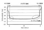
上述のような基板処理装置では、基板保持具に、製品として使用するプロダクト基板の他に、製品として使用されない基板、例えば膜の特性を評価するためのモニタ基板や、プロダクト基板の成膜条件の均一性を保つためのダミー基板を、プロダクト基板の配列の中央や両端に装填して基板処理を行うことがある。 In the substrate processing apparatus as described above, in addition to the product substrate used as a product, the substrate holder includes a substrate not used as a product, for example, a monitor substrate for evaluating the characteristics of a film, and a film forming condition of the product substrate. Dummy substrates for maintaining uniformity may be loaded in the center or both ends of the array of product substrates to perform substrate processing.
しかし、プロダクト基板は表面積が大きく、基板処理を行う際にラジカルの消費が多いために、図15に示されているように、プロダクト基板上の気相中のラジカル濃度が低くなる。一方、モニタ基板はプロダクト基板と比べて表面積が小さく、基板処理を行う際にラジカルの消費が少ないために、図15に示されているように、モニタ基板上の気相中のラジカル濃度が高くなる。そして、ラジカルの消費が少ないモニタ基板上と、ラジカルの消費が多いプロダクト基板上のラジカル濃度の差によって、プロダクトが生じてしまう場合基板間において基板処理が不均一になってしまうローディング効果が発生してしまう。つまり、基板保持具におけるモニタ基板に近いプロダクト基板上では、基板保持具における中央のプロダクト基板上と比べてラジカル濃度が高くなり、形成される膜の膜厚が厚くなってしまう。すなわち、面間均一性が悪化してしまう。また、ベア基板の200倍の大表面積のプロダクト基板に対して基板処理を行う場合には、基板の端部側から供給されるラジカルが基板の中心部に到達するまでに消費されてしまい、基板の中心部に形成される膜の膜厚が基板の端部に形成される膜の膜厚と比べて薄くなることがある。すなわち、面内均一性も悪化してしまう。 However, since the product substrate has a large surface area and consumes a large amount of radicals when the substrate is processed, the radical concentration in the gas phase on the product substrate becomes low as shown in FIG. On the other hand, the monitor substrate has a smaller surface area than the product substrate and consumes less radicals when processing the substrate. Therefore, as shown in FIG. 15, the radical concentration in the gas phase on the monitor substrate is high. Become. Then, when a product is produced due to the difference in radical concentration between the monitor substrate that consumes less radicals and the product substrate that consumes more radicals, a loading effect occurs in which the substrate processing becomes non-uniform between the substrates. It ends up. That is, on the product substrate close to the monitor substrate in the substrate holder, the radical concentration is higher than that on the central product substrate in the substrate holder, and the film thickness of the formed film becomes thicker. That is, the inter-plane uniformity deteriorates. Further, when a substrate is processed on a product substrate having a
本開示は、基板に形成される膜の面間面内均一性を向上することを目的とする。 An object of the present disclosure is to improve the in-plane uniformity of a film formed on a substrate.
本開示の第一態様によれば、
複数の基板を回転軸上に配列させて保持する基板保持具と、
前記基板保持具を収容する反応管と、
前記反応管を取り囲む炉体と、
前記反応管内で保持された複数の基板のそれぞれに対応する複数の流入口を有し、前記複数の流入口から対応する基板の表面に対してそれぞれ平行にガスを供給するガス供給機構と、
前記複数の基板のそれぞれの側方に面する流出口を有し、真空ポンプと流体的に連通し、前記基板の表面を流れたガスを排気するガス排気機構と、を備え、
前記基板保持具は、
前記基板の外径以下の内径を有し、回転軸と直交する面に、前記回転軸と同心に、所定のピッチで配置される複数の円環状部材と、
前記複数の円環状部材の幅よりも狭い幅を有し、前記複数の円環状部材の外周と略一致する外接円に沿って配置され、前記複数の円環状部材を保持する複数の柱と、
前記複数の柱から、内周に向かって伸び、前記複数の円環状部材のそれぞれの間の位置で複数の基板をそれぞれ載置する複数の支持部材と、を有し、
前記基板保持具が前記反応管内に収容されたときに、前記複数の円環状部材の外周と前記反応管の側面との間に、前記基板保持具の回転を可能な隙間が形成され、
前記複数の流入口は、それぞれ、配列された複数の基板の隣接する2枚の基板間に配置され、対応する基板の真上の円環状部材の上面と同じかより高い位置の上端を有するスリット開口として形成された技術が提供される。According to the first aspect of the present disclosure
A board holder that arranges and holdsmultiple boards on the axis of rotation,
A reaction tube that houses thepre-Symbol substrate holder,
The furnace body surrounding the reaction tube and
Aplurality of inlets corresponding to each of theplurality of substrates held by said reaction tube, a gas supply mechanism for supplying parallel to the gasrespectively to the surface of the corresponding substrate from theplurality of inlets,
It has an outlet facing each side of theplurality of substrates, and includes a gas exhaust mechanism that fluidly communicates with a vacuum pump and exhausts gas that has flowed on the surface of the substrate.
The substrate holder is
Has an inner diameter of not more than the outside diameter of the said substrate, the plane perpendicular tothe rotationalaxis, wherein the rotary shaft concentrically, the plurality of annular members disposed at a predetermined pitch,
A plurality of pillars having a width narrower than the width of the plurality of annular members, arranged along an circumscribed circle substantially matching the outer circumference of the plurality of annular members, and holding the plurality of annular members.
From said plurality of posts, extending toward the inner periphery, it has a plurality of support members for supportingaplurality of substrates at a position between each of said plurality of annular members,
When the substrate holder is accommodated in the reaction tube, between the outer and theside surfaceof the reaction tube of the plurality of annular members, betweenclearance as possible rotation of the substrate holder isformed,
The plurality of inlets are slits arranged between two adjacent substrates of the plurality of arranged substrates, each having an upper end at the same or higher position as the upper surface of the annular member directly above the corresponding substrate. The techniqueformed as an opening is provided.
本開示によれば、基板に形成される膜の面間面内均一性を向上させることができる。 According to the present disclosure, it is possible to improve the in-plane uniformity of the film formed on the substrate.
<実施形態>
本開示の一実施形態に係る基板処理装置の一例について図1〜図11に従って説明する。なお、図中に示す矢印Hは装置上下方向(鉛直方向)を示し、矢印Wは装置幅方向(水平方向)を示し、矢印Dは装置奥行方向(水平方向)を示す。<Embodiment>
An example of the substrate processing apparatus according to the embodiment of the present disclosure will be described with reference to FIGS. 1 to 11. The arrow H shown in the figure indicates the device vertical direction (vertical direction), the arrow W indicates the device width direction (horizontal direction), and the arrow D indicates the device depth direction (horizontal direction).
(基板処理装置10の全体構成)
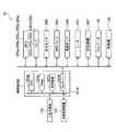
基板処理装置10は、図1に示されるように、各部を制御する制御部280及び処理炉202を備え、処理炉202は、ウエハ200を加熱するヒータ207を有する。ヒータ207は円筒形状であり、反応管203を取り囲むよう構成され、図示しないヒータベースに支持されることにより装置上下方向に据え付けられている。ヒータ207は、処理ガスを熱で活性化させる活性化機構としても機能する。なお、制御部280については、詳細を後述する。(Overall configuration of substrate processing device 10)
As shown in FIG. 1, the
反応管203は、ヒータ207の内側に立てて配置され、ヒータ207と同心円状に反応容器を構成する。反応管203は、例えば高純度溶融石英(SiO2)または炭化シリコン(SiC)等の耐熱性材料により形成されている。基板処理装置10は、いわゆるホットウォール型である。The
反応管203は、後述する回転軸と同軸の円筒面によって構成された側面と天井を有し、ウエハ200に直接面する内管12と、内管の外側に広い隙間(間隙S)を隔てて内管12を囲むように設けられた円筒状の外管14とを有している。内管12は、外管14と同心円状に配置される。内管12は、管部材の一例である。外管14は、耐圧性を有する。 The
内管12は、下端が開放され、上端が平坦状の天井で閉塞される。また、外管14も、下端が開放され、上端が平坦状の天井で完全に閉塞される。さらに、内管12と外管14との間に形成された間隙Sには、図2に示したように、複数(本実施形態では3個)のノズル室222が形成されている。なお、ノズル室222については、詳細を後述する。 The lower end of the
この内管12の側面と天井に囲まれた空間には、図1及び図2に示したように、基板としてのウエハ200を処理する処理室201が形成されている。また、この処理室201は、ウエハ200を水平姿勢で垂直方向に多段に整列した状態で保持可能な基板保持具の一例であるボート217を収容可能とし、内管12は、収容されたウエハ200を包囲する。なお、内管12については、詳細を後述する。 As shown in FIGS. 1 and 2, a
反応管203の下端は、円筒体状のマニホールド226によって支持されている。マニホールド226は、例えばニッケル合金やステンレス等の金属で構成されるか、又は石英若しくはSiC等の耐熱耐蝕材料で構成されている。マニホールド226の上端部にはフランジが形成されており、このフランジ上に外管14の下端部が設置されている。このフランジと外管14の下端部との間には、Oリング等の気密部材220が配置されており、反応管203内を気密状態にしている。 The lower end of the
マニホールド226の下端の開口部には、蓋(シールキャップ)219がOリング等の気密部材220を介して気密に取り付けられており、反応管203の下端の開口部側、すなわちマニホールド226の開口部が気密に塞がれている。蓋219は、例えばニッケル合金やステンレス等の金属で構成され、円盤状に形成されている。蓋219は、石英(SiO2)または炭化シリコン(SiC)等の耐熱性材料でその外側を覆うように構成してもよい。A lid (seal cap) 219 is airtightly attached to the opening at the lower end of the manifold 226 via an
蓋219上にはボート217を支持するボート支持台218が設けられている。ボート支持台218は、例えば石英やSiC等で構成され断熱部として機能する。 A
ボート217は、ボート支持台218上に立設されている。ボート217は、例えば石英やSiC等で構成されている。ボート217は、ボート支持台218に取り付けられる後述する底板とその上方に配置された天板とを有しており、底板と天板との間に複数本の柱217a(図2参照)が架設されている。 The
ボート217には、内管12内の処理室201で処理される複数枚のウエハ200が保持されている。複数枚のウエハ200は、互いに一定の間隔をあけながら水平姿勢を保持し、かつ互いに中心を揃えた状態でボート217内に支持されており、積載方向が反応管203の軸方向となる。つまり、ウエハ200の中心がボート217の中心軸にあわせられ、ボート217の中心軸は反応管203の中心軸に一致する。なお、ボート217については、詳細を後述する。 The
蓋219の下側には、ボートを回転可能に保持する回転機構267が設けられている。回転機構267の回転軸(シャフト)265は、蓋219を貫通してボート支持台218に接続されており、回転機構267によって、ボート支持台218を介してボート217を回転させることでウエハ200を回転させる。 A
蓋219は、反応管203の外部に設けられた昇降機構としてのエレベータ115によって垂直方向に昇降され、ボート217を処理室201に対して搬入、及び搬出することができる。 The
マニホールド226の内面には、処理室201の内部にガスを供給するガスノズル(インジェクター)340a,340b,340cを支持するノズル支持部350a,350b,350cが(図3参照)設置されている(図1ではガスノズル340a、ノズル支持部350aのみ図示)。ノズル支持部350a,350b,350cは、例えばニッケル合金やステンレス等の材料により構成されている。 On the inner surface of the manifold 226,
ノズル支持部350a,350b,350cの一端には、処理室201の内部へガスを供給するガス供給管310a,310b,310cが夫々接続され、他端には、ガスノズル340a,340b,340cが夫々接続されている。ガスノズル340a,340b,340cは、例えば石英またはSiC等のパイプを所望の形状に形成して構成されている。なお、ガスノズル340a,340b,340c、及びガス供給管310a,310b,310cについては、詳細を後述する。
一方、反応管203の外管14には、隙間Sと流体的に連通する排気ポート230が形成されている。排気ポート230は、外管14の下端部に隣接して、後述する第二排気口237よりも下方に形成される。 On the other hand, the
排気管231は、排気ポート230と真空排気装置としての真空ポンプ246とを、流体連通させる。排気管231の途中には、処理室201の内部の圧力を検出する圧力センサ245、及び圧力調整器としてのAPC(Auto Pressure Controller)バルブ244が設けられる。真空ポンプ246の出口は、図示しない廃ガス処理装置等に接続されている。これにより、真空ポンプ246の出力及びAPCバルブ244の開度を制御することで、処理室201の内部の圧力が所定の圧力(真空度)となるように構成されている。 The
また、反応管203の内部には、温度検出器としての図示しない温度センサが設置されており、温度センサにより検出された温度情報に基づいて、ヒータ207への供給電力を調整することで、処理室201の内部の温度が所望の温度分布となるように構成されている。 Further, a temperature sensor (not shown) as a temperature detector is installed inside the
この構成において、処理炉202では、バッチ処理される複数枚のウエハ200を多段に積載するボート217がボート支持台218によって処理室201の内部へ搬入される。そして、処理室201へ搬入されたウエハ200を、ヒータ207によって所定の温度に加熱する。このような処理炉を有する装置は、縦型バッチ装置と呼ばれる。 In this configuration, in the
(要部構成)
次に、内管12、ノズル室222、ガス供給管310a,310b,310c、ガスノズル340a,340b,340c、ボート217及び制御部280について説明する。(Main part composition)
Next, the
〔内管12〕
内管12の周壁には、図2〜図5に示されるように、ガスを処理室201内へ流入させる流入口としての供給スリット235a,235b,235cと、供給スリット235a,235b,235cと対向するように、処理室201内のガスを間隙Sへ流出させる流出口としての第一排気口236が形成されている。また、内管12の周壁において第一排気口236の下方には、第一排気口236より開口面積が小さい排出部の一例である第二排気口237が形成されている。このように、供給スリット235a,235b,235cと、第一排気口236、第二排気口237とは、内管12の周方向において異なる位置に形成され、対向する位置に形成されている。[Inner tube 12]
On the peripheral wall of the
内管12に形成された第一排気口236は、図1、図5に示されるように、ウエハ200のそれぞれの側方に面し、処理室201のウエハ200が収容される領域(以下「ウエハ領域」と呼ぶ)に形成されている。また、第一排気口236は、中心軸からみて第一排気口236と同じ方向に、中心軸方向においてウエハ領域に亘って形成されている。また、第一排気口236は、排気ポート230を介して真空ポンプ246と流体的に連通し、ウエハ200の表面を流れたガスを排気する。第二排気口237は、排気ポート230の上端よりも高い位置から排気ポート230の下端よりも高い位置まで形成され、処理室201の下方の雰囲気を排気する。 As shown in FIGS. 1 and 5, the
すなわち、第一排気口236は、処理室201の内部の雰囲気を間隙Sに排気するガス排気口であり、第一排気口236から排気されたガスは、間隙S内を大よそ下向きに流れ、排気ポート230を介して、反応管203の外部へ排気される。同様に、第二排気口237から排気されたガスは、間隙Sの下側及び排気ポート230を介して、反応管203の外部へ排気される。 That is, the
この構成において、ウエハ200の表面を流れた後のガスが間隙S全体を流路として最短距離で排気されることで、第一排気口236と排気ポート230の間の圧力損失を最小限とすることができる。これにより、ウエハ領域の圧力を下げ、或いはウエハ領域の流速を上げ、ローディング効果を緩和することができる。 In this configuration, the gas after flowing on the surface of the
一方、内管12の周壁に形成された供給スリット235aは、図3及び図4に示されるように、横長のスリット開口で上下方向に複数形成されており、第一ノズル室222aと処理室201とを連通している。 On the other hand, as shown in FIGS. 3 and 4, a plurality of
また、供給スリット235bは、横長のスリット開口で上下方向に複数形成されており、供給スリット235aの側方に配置されている。さらに、供給スリット235bは、第二ノズル室222bと処理室201とを連通している。 Further, a plurality of
また、供給スリット235cは、横長のスリット開口で上下方向に複数形成されており、供給スリット235bを挟んで供給スリット235aの反対側に配置されている。さらに、供給スリット235cは、第三ノズル室222cと処理室201とを連通している。 Further, a plurality of
図5に示されるように、供給スリット235a,235b,235cは、上下方向において、処理室201に収容された状態のボート217に複数段載置された隣り合うウエハ200間、及び最上段のウエハ200とボート217の天板217cの間に夫々配置されるように形成されている。これにより、反応管203内で保持されたウエハ200のそれぞれに対応する供給スリット235a〜235cから対応するウエハ200にガスがそれぞれ供給され、ウエハ200の表面には、平行なガス流れが形成される。 As shown in FIG. 5, the
更に、供給スリット235a,235b,235cは、後述するセパレートリング400と協働して、対応するウエハ200の表面へ届くガスを最大化することを意図して、その位置が設定される。具体的には、供給スリット235a,235b,235cは、図5に示されているように、それぞれ対応するウエハ200の上面と略同じ高さに位置する下端と、それぞれ対応するウエハ200の直上のセパレートリング400の上面と同じかより高い高さに位置する上端を有する。この配置では、ガスの多くが対応するウエハ200とその直上のセパレートリング400の間を流れる。なお、供給スリット235a,235b,235cの下端は、対応するウエハ200の直下のセパレートリング400の上面より高くなければならず、対応するウエハの下面より高いことが好ましい。また上端は、対応するウエハ200の直上のウエハ200の下面よりも低くなければならず、直上のセパレートリング400の下面と略同じ高さまで容易に下げることができる。 Further, the
また、供給スリット235a,235b,235cは、ボート217に載置可能な最下段のウエハ200とボート217の底板の間の位置にも形成することができる。この場合、供給スリット235a等の縦方向に並ぶ数は、ウエハ200の数より1多くなる。 Further, the
また、供給スリット235a,235b,235cの内管12の周方向の長さを、各ノズル室222a,222b,222cの周方向の長さと同じにすると、ガス供給効率が向上するので良い。 Further, if the length of the
また、供給スリット235a,235b,235cは、四隅としてのエッジ部が曲面を描くように滑らかに形成されている。エッジ部にRがけ等を行い、曲面状にすることにより、エッジ部周縁のガスのよどみを抑制することができ、エッジ部に膜が形成されるのを抑制することができ、さらに、エッジ部に形成される膜の膜剥がれを抑制することができる。 Further, the
また、内管12の供給スリット235a,235b,235c側の内周面12aの下端には、ガスノズル340a,340b,340cをノズル室222の対応する各ノズル室222a,222b,222cに設置するための開口部256が形成されている。 Further,
〔ノズル室222〕
ノズル室222は、図2、図4に示されるように、内管12の外周面12cと外管14の内周面14aとの間の間隙Sに形成されている。ノズル室222は、上下方向に延びている第一ノズル室222a、第二ノズル室222b、及び第三ノズル室222cを備えている。また、第一ノズル室222aと、第二ノズル室222bと、第三ノズル室222cとは、この順番で処理室201の周方向に並んで形成されている。第一ノズル室222a、第二ノズル室222b、及び第三ノズル室222cは、供給室(供給バッファ)の一例である。[Nozzle chamber 222]
As shown in FIGS. 2 and 4, the
具体的には、内管12の外周面12cから外管14へ向けて平行に延出した第一仕切18aと第二仕切18bとの間で、かつ、第一仕切18aの先端と第二仕切18bの先端とを繋ぐ円弧状の外壁20と内管12との間に、ノズル室222が形成されている。 Specifically, between the
さらに、ノズル室222の内部には、内管12の外周面12cから外壁20側へ向けて延出した第三仕切18cと、第四仕切18dとが形成されており、第三仕切18cと第四仕切18dとは、この順番で第一仕切18aから第二仕切18b側へ並んでいる。また、外壁20は、外管14と離間している。さらに、第三仕切18cの先端、及び第四仕切18dの先端は、外壁20に達している。各仕切18a〜18d、及び外壁20は、区画部材の一例である。 Further, inside the
また、各仕切18a〜18d、及び外壁20は、ノズル室222の天井部から反応管203の下端部まで形成されている。具体的に、第三仕切18cの下端、及び第四仕切18dの下端は、図3に示したように、開口部256の上縁よりも下側まで形成される。 Further, the
そして、第一ノズル室222aは、図2に示されるように、内管12、第一仕切18a、第三仕切18c、及び外壁20に囲まれて形成されており、第二ノズル室222bは、内管12、第三仕切18c、第四仕切18d、及び外壁20に囲まれて形成されている。さらに、第三ノズル室222cは、内管12、第四仕切18d、第二仕切18b、及び外壁20に囲まれて形成されている。これにより、各ノズル室222a,222b,222cは、下端部が開放されると共に上端が内管12の天面を構成する壁体で閉塞された有天井形状で、上下方向に延びている。 As shown in FIG. 2, the
そして、前述したように、第一ノズル室222aと処理室201を連通する供給スリット235aが、図3に示されるように、上下方向に並んで、内管12の周壁に形成されている。また、第二ノズル室222bと処理室201を連通する供給スリット235bが、上下方向に並んで、内管12の周壁に形成されており、第三ノズル室222cと処理室201を連通する供給スリット235cが、上下方向に並んで、内管12の周壁に形成されている。 Then, as described above, the
〔ガスノズル340a,340b,340c〕
ガスノズル340a,340b,340cは、上下方向に延びており、図2に示したように、各ノズル室222a,222b,222cに夫々設置されている。具体的には、ガス供給管310aに連通するガスノズル340aは、第一ノズル室222aに配置されている。さらに、ガス供給管310bに連通するガスノズル340bは、第二ノズル室222bに配置されている。また、ガス供給管310cに連通するガスノズル340cは、第三ノズル室222cに配置されている。[
The
ここで、上方から見て、ガスノズル340bは、処理室201の周方向において、ガスノズル340aとガスノズル340cとに挟まれている。また、ガスノズル340aと、ガスノズル340bとは、第三仕切18cによって仕切られており、ガスノズル340bと、ガスノズル340cとは、第四仕切18dによって仕切られている。これにより、各ノズル室222間で、ガスが混ざり合うことを抑制することができる。 Here, when viewed from above, the
ガスノズル340a,340b,340cは、I字型のロングノズルとして夫々構成されている。ガスノズル340a,340b,340cの周面には、図3に示されるように、供給スリット235a,235b,235cと夫々対向するようにガスを噴射する噴射孔234a,234b,234cが夫々形成されている。具体的には、ガスノズル340a,340b,340cの噴射孔234a,234b,234cは各供給スリット235に対し1個ずつ対応するように、各供給スリット235a,235b,235cの縦幅の中央部分に形成すると良い。或いは、図5に示すように、噴射孔234a等の中心を通る水平線が、対応するウエハ200の上面と、直上のセパレートリング400の間に位置するように、その高さ方向の位置が設定される。 The
本実施形態では、噴射孔234a,234b,234cは、ピンホール状とされ、縦方向のサイズ(直径)は、対応する供給スリット235aの高さ方向のサイズより小さい。また、ガスノズル340aの噴射孔234aからガスが噴射される噴射方向は、上方から見て、処理室201の中心に向いており、側方から見て、図5に示されるように、ウエハ200とウエハ200との間、最上位のウエハ200の上面の上側部分、又は最下位のウエハ200の下面の下側部分を向いている。 In the present embodiment, the
このように、噴射孔234a,234b,234cが上下方向で形成されている範囲は、ウエハ200が上下方向で配置されている範囲を覆っている。さらに、夫々の噴射孔234a,234b,234cからガスが噴射される噴射方向は、同じ方向とされている。 As described above, the range in which the
この構成において、各ガスノズル340a,340b,340cの噴射孔234a,234b,234cから噴射されたガスは、各ノズル室222a,222b,222cの前壁を構成する内管12に形成された供給スリット235a,235b,235cを通って処理室201へ供給される。そして、処理室201へ供給されたガスは、夫々のウエハ200の上面及び下面に沿って平行に流れる。 In this configuration, the gas injected from the
〔ガス供給管310a,310b,310c〕
ガス供給管310aは、図1に示されるように、ノズル支持部350aを介してガスノズル340aと連通しており、ガス供給管310bは、ノズル支持部350bを介してガスノズル340bと連通している。また、ガス供給管310cは、ノズル支持部350cを介してガスノズル340cと連通している。[
As shown in FIG. 1, the
ガス供給管310aには、ガスの流れ方向において上流側から順に、処理ガスとしての第1原料ガス(反応ガス)を供給する原料ガス供給源360a、流量制御器の一例であるマスフローコントローラ(MFC)320a、及び開閉弁であるバルブ330aが夫々設けられている。 The
ガス供給管310bには、上流方向から順に、処理ガスとしての第2原料ガスを供給する原料ガス供給源360b、MFC320b、及びバルブ330bが夫々設けられている。 The
ガス供給管310cには、上流方向から順に、処理ガスとしての不活性ガスを供給する不活性ガス供給源360c、MFC320c、及びバルブ330cが夫々設けられている。 The
ガス供給管310aのバルブ330aよりも下流側には、不活性ガスを供給するガス供給管310dが接続されている。ガス供給管310dには、上流方向から順に、処理ガスとしての不活性ガスを供給する不活性ガス供給源360d、MFC320d、及びバルブ330dが夫々設けられている。 A
また、ガス供給管310bのバルブ330bよりも下流側には、不活性ガスを供給するガス供給管310eが接続されている。ガス供給管310eには、上流方向から順に、処理ガスとしての不活性ガスを供給する不活性ガス供給源360e、MFC320e、及びバルブ330eが夫々設けられている。なお、不活性ガスを供給する不活性ガス供給源360c,360d,360eは、共通の供給元に接続されている。 Further, a
また、ガス供給管310aから供給する第1原料ガスとしては、アンモニア(NH3)ガスが挙げられる。また、ガス供給管310bから供給する第2原料ガスとしては、シリコン(Si)ソースガスが挙げられる。さらに、各ガス供給管310c,310d,310eから供給する不活性ガスとしては、窒素(N2)ガスが挙げられる。Further, as the first raw material gas supplied from the
ガス供給管310a,310b,310c、ガスノズル340a,340b,340c、噴射孔234a,234b,234c、供給スリット235a,235b,235c等により、ウエハ200の表面に対して平行にガスを供給し、中心軸に向けて吐出するガス供給機構が構成される。また、第一排気口236、第二排気口237、排気ポート230、排気管231及び真空ポンプ246等により、ウエハ200の表面を流れたガスを排気するガス排気機構が構成される。 Gas is supplied parallel to the surface of the
〔ボート217〕
次に、ボート217について図6〜図9を用いて詳述する。
ボート217は、円板形状の底板217bと、円板形状の天板217cと、底板217bと天板217cとを垂直方向に架設する複数の柱217a(本実施形態では5つ)を有する。複数の柱217aの、底板217bと天板217cの間には、円環状部材としてのセパレートリング400が、略水平に、垂直方向に複数設けられている。また、セパレートリング400のそれぞれの間には、ウエハ200を略水平に保持するための支持部材としての支持ピン221が設けられている。[Boat 217]
Next, the
The
底板217bには、ボート217をボート支持台218に固定させるためのボルト装着孔217eが複数(本実施形態では3つ)形成されている。また、底板217bの底面には、ボート217をボート支持台218上に立設させる四角形状の脚部217dが複数(本実施形態では3つ)設けられている。 The
セパレートリング400は、図7(A)及び図7(B)に示すように、平坦な平板状の円環形状の部材である。また、セパレートリング400の外周面には、切欠き400aが複数(本実施形態では5つ)形成されている。これらの切欠き400aが、それぞれ柱217aに当接される。 As shown in FIGS. 7 (A) and 7 (B), the
セパレートリング400は、柱217aとの当接部分を除き一定の幅および厚みを有する。セパレートリング400の内径は、例えば296mmであって、ウエハ200の外径(例えば300mm)以下に構成されている(図9(B)及び図9(C)参照)。また、セパレートリング400の外径は、例えば315mmであって、ウエハ200の外径よりも大きく構成されている(図9(B)及び図9(C)参照)。ここで、セパレートリング400の幅とは、セパレートリング400の外径とセパレートリング400の内径との差である。セパレートリングの内径は、例えば280〜300mmである。また、セパレートリング400の幅は、例えば5〜20mmである。また、セパレートリング400の厚さは、ガス流れを阻害しない厚さであって、強度的にも問題のない厚さである例えば1〜2mmであって、例えば1.5mmである。 The
切欠き400aは、例えば図7に示されるように、セパレートリング400の対向する位置と、対向する位置から半円部分に等間隔に、柱217aと同じ数(本実施形態では5つ)形成され、セパレートリング400をボート217内に略水平に差し込み可能にする。切欠き400aの差し込み方向手前側は、図8に示すように、対応する柱217aと同一形状であって、切欠き400aの差し込み方向奥側は、対応する柱217aを差し込み方向に投影した形状となっている。なお柱217aに溝を設けた場合、切欠き400aは溝のある高さにおける断面形状に対応させることができ、より小さくなる。 As shown in FIG. 7, for example, the
柱217aは、周方向に長く半径方向に短い矩形の多角柱であって、複数の柱217a(本実施形態では5つ)で複数のセパレートリング400を保持する。また、セパレートリング400のそれぞれの間の複数の柱217aのうち少なくとも3つの柱217aには、それぞれ支持ピン221が設けられている。柱217aは、それぞれセパレートリング400の幅よりも狭い幅を有し、図8に示すように、セパレートリング400の外周と略一致する外接円に沿って配置されている。 The
セパレートリング400は、図8に示すように、複数の切欠き400aをそれぞれ柱217aに当接若しくは近接させて、柱217aのいずれかと少なくとも3点で溶接されることで、ボート217と一体化される。なお一体化の前に、それぞれの部材は個別にファイアポリッシュされうる。そして、複数のセパレートリング400が、処理室201内において、回転軸265上と直交する面に、回転軸265と同心に、所定の間隔(ピッチ)で柱217aに固定配置される。つまり、セパレートリング400の中心がボート217の中心軸にあわせられ、ボート217の中心軸は反応管203の中心軸および回転軸265に一致する。すなわち、複数のセパレートリング400は、互いに一定の間隔をあけながら水平姿勢を保持し、かつ互いに中心を揃えた状態でボート217の柱217aに支持されており、積載方向が反応管203の軸方向となる。 As shown in FIG. 8, the
また、セパレートリング400の半径と、柱217aの中心軸からの最大距離は同じであって、切欠き400aを、それぞれ柱217aに当接させた際に、セパレートリング400の外面と柱217aの外面が連続するよう構成されている。これにより、ボート217と反応管203の間のクリアランスを減らすことなく、ウエハ200と反応管203の内面との隙間を実質的に埋めることができる。 Further, the radius of the
支持ピン221は、図8に示されているように、複数の柱217aのうちの少なくとも3本の柱217aから、内周に向かって略水平に伸びるように設けられている。支持ピン221は、例えばセパレートリング400の差し込み方向奥側の柱217aと、セパレートリング400の差し込み方向手前側の柱217aに設けられている。セパレートリング400の差し込み方向手前側の柱217aに設けられた支持ピン221は、ウエハ200の重心を支えるため、柱217aの形成されていない方向に斜め出しされている。言い換えれば、ウエハ200の搬送方向手前側(セパレートリング400の差し込み方向手前側)に斜め出しされている。また、支持ピン221は、少なくとも3本の柱217aのそれぞれに、所定の間隔(ピッチ)で設けられている。これにより、支持ピン221は、セパレートリング400のそれぞれの間の略中央の位置で、所定のピッチでウエハ200を載置する。支持ピン221の外径は、例えば3mmである。 As shown in FIG. 8, the
すなわち、3本の支持ピン221が、セパレートリング400のそれぞれの間の略中央の位置で、ウエハ200を略水平に保持し、複数のウエハ200をセパレートリング400のそれぞれの間で所定のピッチで保持する。セパレートリング400は、積層されるウエハ200の中間付近に設けられている。これにより、ウエハ200の下方には、ウエハ200を載せて運ぶエンドエフェクタを挿入するための空間が、ウエハ200の上方には、ウエハ200をすくい上げて搬送するための空間が、それぞれ確保される。 That is, the three
上述したようなセパレートリング400が設けられたボート217が、反応管203内に収容されると、セパレートリング400の外周と内管12の内周面12aとの間に、ボート217の回転を可能な程度の狭い隙間(間隙G)が形成される(図2参照)。この隙間(間隙G)は、ウエハの直径が200mm以上の場合、ウエハ200の直径の1〜3%である。具体的には、例えば、ウエハの直径が300mmの場合には、3〜9mmである。1%未満の隙間は、ボート217の内管12への接触の危険を高める。3%を超える隙間は、噴射孔234からのガスが対応するウエハ200以外のウエハに拡散する割合を増加させる(すなわち、セパレートリングの整流効果が減退する)。 When the
このように、セパレートリング400を用いて、外周と内管12の内周面12aとの間の隙間(間隙G)を小さくすることにより、それぞれのウエハ200上への処理ガスの流入量が増加し、面内均一性が向上される。また、セパレートリングを用いて、隙間(間隙G)を小さくすることで、ウエハ200の上下方向の拡散が抑制され、ウエハ200端部への増膜が抑制されて、面内均一性が向上される。具体的には、供給スリット235a〜235cからのガスの90%以上を、ウエハ200の表面に対して平行に供給することが可能となる。言い換えれば、ウエハ200端部での上下方向への拡散を抑制することが可能となる。 In this way, by using the
なお、セパレートリング間のピッチは、ウエハの直径が200mm以上の場合、ウエハ200の直径の4〜17%である。具体的には、例えば、ウエハの直径が300mmの場合には、12〜51mmであって、例えば12.5mmである。4%未満のピッチは、エンドエフェクタによるウエハの移載が困難になり、17%を超えるピッチは、装置の生産性の低下を招く。 The pitch between the separate rings is 4 to 17% of the diameter of the
なお、セパレートリング400は、上述したように円環形状であって、中央が開口している。つまり、ウエハ200の上下間で空間を完全には分離しないよう構成されている。これにより、膜厚が薄くなるウエハ中心部で、流路の高さがウエハ間隔にまで広がることで、流速の低下を防ぎ、流入量を確保することができるほか、未反応ガスがセパレートリングの中央開口から補給されうる。すなわち、図5に示すように、あるウエハ200に対応する供給スリット235aから流入したガスは、ウエハ200の直上のセパレートリング400の上と下を流れる2つの流れに分かれ、中央開口にて合流する。 As described above, the
〔制御部280〕
図10は、基板処理装置10を示すブロック図であり、基板処理装置10の制御部280(所謂コントローラ)は、コンピュータとして構成されている。このコンピュータは、CPU(Central Processing Unit)121a、RAM(Random Access Memory)121b、記憶装置121c、及びI/Oポート121dを備えている。[Control unit 280]
FIG. 10 is a block diagram showing the
RAM121b、記憶装置121c、I/Oポート121dは、内部バス121eを介して、CPU121aとデータ交換可能なように構成されている。制御部280には、例えばタッチパネル等として構成された入出力装置122が接続されている。 The
記憶装置121cは、例えばフラッシュメモリ、HDD(Hard Disk Drive)等で構成されている。記憶装置121c内には、基板処理装置の動作を制御する制御プログラムや、後述する基板処理の手順や条件等が記載されたプロセスレシピ等が、読み出し可能に格納されている。 The
プロセスレシピは、後述する基板処理工程における各手順を制御部280に実行させ、所定の結果を得ることが出来るように組み合わされたものであり、プログラムとして機能する。以下、プロセスレシピや制御プログラム等を総称して、単に、プログラムともいう。 The process recipes are combined so that the
本明細書においてプログラムという言葉を用いた場合は、プロセスレシピ単体のみを含む場合、制御プログラム単体のみを含む場合、または、それらの両方を含む場合がある。RAM121bは、CPU121aによって読み出されたプログラムやデータ等が一時的に保持されるメモリ領域(ワークエリア)として構成されている。 When the term program is used in the present specification, it may include only a process recipe alone, a control program alone, or both of them. The
I/Oポート121dは、上述のMFC320a〜320e、バルブ330a〜330e、圧力センサ245、APCバルブ244、真空ポンプ246、ヒータ207、温度センサ、回転機構267、エレベータ115、移載機124等に接続されている。 The I /
CPU121aは、記憶装置121cから制御プログラムを読み出して実行すると共に、入出力装置122からの操作コマンドの入力等に応じて記憶装置121cからプロセスレシピを読み出すように構成されている。 The
CPU121aは、読み出したプロセスレシピの内容に沿うように、MFC320a〜320eによる各種ガスの流量調整動作、バルブ330a〜330eの開閉動作、APCバルブ244の開閉動作を制御するように構成されている。また、CPU121aは、圧力センサ245に基づくAPCバルブ244による圧力調整動作、真空ポンプ246の起動及び停止、温度センサに基づくヒータ207の温度調整動作を制御するように構成されている。さらに、CPU121aは、回転機構267によるボート217の回転及び回転速度調節動作、エレベータ115によるボート217の昇降動作、ボート217との間でウエハ200の移載を行う移載機124による動作等を制御するように構成されている。 The
制御部280は、専用のコンピュータとして構成されている場合に限らず、汎用のコンピュータとして構成されていてもよい。例えば、上述のプログラムを格納した外部記憶装置123を用意し、この外部記憶装置123を用いて汎用のコンピュータにプログラムをインストールすること等により、本実施形態の制御部280を構成することができる。外部記憶装置としては、例えば、ハードディスク等の磁気ディスク、CD等の光ディスク、MO等の光磁気ディスク、USBメモリ等の半導体メモリ等が挙げられる。 The
(作用)
次に、本開示に関わる基板処理装置の動作概要を、図11に示す窒化シリコン膜の成膜を例に用いて説明する。これらの動作は、制御部280によって制御される。なお、反応管203には、予め所定枚数のウエハ200が載置されたボート217が搬入されており、蓋219によって反応管203が気密に閉塞されている。なお、ウエハ200は、パターンが形成されたプロダクト基板と、パターンが形成されていない少なくとも1つのモニタ基板等を含む。モニタ基板は、基板処理の結果を評価するために、ボート217の代表的な位置(例えば、中央、上端付近、下端付近)に、プロダクト基板と混ざって配列される。(Action)
Next, an outline of the operation of the substrate processing apparatus according to the present disclosure will be described using the film formation of the silicon nitride film shown in FIG. 11 as an example. These operations are controlled by the
制御部280による制御が開始されると、制御部280は、図1に示す真空ポンプ246及びAPCバルブ244を作動して排気ポート230から反応管203の内部の雰囲気を排気する。さらに、制御部280は、回転機構267を制御し、ボート217の回転を開始する。なお、この回転については、少なくとも、ウエハ200に対する処理が終了するまでの間は継続して行われる。 When the control by the
図11に示す成膜シーケンスでは、第1の処理工程、第1の排出工程、第2の処理工程、及び第2の排出工程を1サイクルとし、この1サイクルを所定回数繰り返してウエハ200に対する成膜が完了する。そして、この成膜が完了すると、ボート217が反応管203の内部から搬出される。そして、ウエハ200は、移載機124により、ボート217から移載棚のポッドに移載され、ポッドは、ポッド搬送機により、移載棚からポッドステージに移載され、外部搬送装置により、筐体の外部に搬出される。 In the film forming sequence shown in FIG. 11, the first processing step, the first discharging step, the second processing step, and the second discharging step are set as one cycle, and this one cycle is repeated a predetermined number of times to form the
ここで、移載機124は、ボート217へ側方からエンドエフェクタを挿入し、ボート217の支持ピン221上に載置されたウエハ200を直接すくい上げてエンドエフェクタ上に移載する。エンドエフェクタは、支持ピン221に載置されるウエハ200の裏面とウエハ200の下側のセパレートリング400の上面との間(例えば6.9mm)よりも小さな厚みを有し、例えば3mm〜6mmである。すなわち、エンドエフェクタが、ウエハ200の裏面とウエハ200の下側のセパレートリング400の上面との間よりも小さな厚みを有し、セパレートリング400が一定の幅および厚みを有するため、本実施形態では、エンドエフェクタによるすくい上げの際にもセパレートリング400に干渉せずにそのまま移載を行うことができる。すなわち、セパレートリング400にエンドエフェクタを挿入する際にエンドエフェクタを通過させるための切り込みをセパレートリング400に設けなくてもよい。これによりウエハ処理の面内均一性が向上する。 Here, the
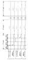
以下、図11に示す成膜シーケンスを詳述する。図11には、本実施形態に係る成膜シーケンスにおけるガスの供給量(縦軸)と、ガス供給のタイミング(横軸)とがグラフで示されている。なお、成膜シーケンスが実行される前の状態では、バルブ330a〜330eは、閉じられている。 Hereinafter, the film formation sequence shown in FIG. 11 will be described in detail. FIG. 11 is a graph showing the gas supply amount (vertical axis) and the gas supply timing (horizontal axis) in the film forming sequence according to the present embodiment. In the state before the film formation sequence is executed, the
−第1の処理工程−
制御部280による各部の制御によって、排気ポート230から反応管203の内部の雰囲気が排気されると、制御部280は、バルブ330b,330c,330dを開作動して、ガスノズル340bの噴射孔234bから第2原料ガスとしてシリコン(Si)ソースガスを噴射させる。さらに、ガスノズル340aの噴射孔234a、及びガスノズル340cの噴射孔234cから不活性ガス(窒素ガス)を噴射させる。つまり、制御部280は、第二ノズル室222bに配置されているガスノズル340bの噴射孔234bから処理ガスを噴出させる。-First processing step-
When the atmosphere inside the
また、制御部280は、バルブ330d、330cを開作動して、ガスノズル340a、340cの噴射孔234a、234cから膜厚制御ガスとしての不活性ガス(窒素ガス)を噴射させる。膜厚制御ガスは、面内均一性(特に基板中央と端における膜厚に差が無いこと)を制御することが可能なガスである。 Further, the
つまり、制御部280は、ガスノズル340bからシリコンソースガスを供給し、ガスノズル340bの両側に設けられたガスノズル340aとガスノズル340cから不活性ガスを供給するように制御する。ガスノズル340bは、シリコンソースガスを中心軸に向けて供給する。ガスノズル340aとガスノズル340cは、不活性ガスが、ウエハ200の縁に沿って第一排気口236、第二排気口237へ流れるように供給する。このとき、ガスノズル340bは、処理ガス供給部として機能する。また、一対のガスノズル340aとガスノズル340cは、不活性ガス供給部として機能する。 That is, the
このとき、制御部280は、圧力センサ245から得られる圧力が一定になるように真空ポンプ246及びAPCバルブ244を作動して反応管203の内部の雰囲気を排気ポート230から排出し、反応管203の内部を大気圧よりも低圧する。 At this time, the
−第1の排出工程−
所定時間経過して第1の処理工程が完了すると、制御部280は、バルブ330bを閉作動して、ガスノズル340bからの第2原料ガスの供給を停止する。さらに、制御部280は、バルブ330eを開作動して、ガスノズル340bから不活性ガス(窒素ガス)の供給を開始する。バルブ330c,330dは開のまま、MFC320c,320dの流量を低下させて、ガスノズル340aの噴射孔234aとガスノズル340cの噴射孔234cから逆流防止ガスとしての不活性ガス(窒素ガス)を噴射させる。逆流防止ガスは、処理室201からノズル室222内へのガス拡散を防止することを目的としたガスであり、ノズルを介さずにノズル室222に直接供給してよい。-First discharge process-
When the first processing step is completed after a lapse of a predetermined time, the
また、制御部280は、真空ポンプ246及びAPCバルブ244を制御し、反応管203の内部の負圧の度合を大きくする等して、反応管203の内部の雰囲気を排気ポート230から排気する。なお、バルブ330eを開いた直後は、比較的大流量(好ましくは第1の処理工程におけるシリコンソースガスと同じ流量)の不活性ガスが供給されうる。 Further, the
−第2の処理工程−
所定時間経過して第1の排出工程が完了すると、制御部280は、バルブ330aを開作動して、ガスノズル340aの噴射孔234aから第1原料ガスとしてアンモニア(NH3)ガスを噴射させる。この間、制御部280は、バルブ330dを閉作動して、ガスノズル340aからの逆流防止ガスとしての不活性ガス(窒素ガス)の供給を停止する。-Second processing process-
When the first discharge step is completed after a lapse of a predetermined time, the
このとき、制御部280は、圧力センサ245から得られる圧力が一定になるように真空ポンプ246及びAPCバルブ244を作動して反応管203の内部の雰囲気を排気ポート230から排出し、反応管203の内部を負圧とする。 At this time, the
−第2の排出工程−
所定時間経過して第2の処理工程が完了すると、制御部280は、バルブ330aを閉作動して、ガスノズル340aからの第1原料ガスの供給を停止する。また、制御部280は、バルブ330dを開作動して、ガスノズル340aの噴射孔234aから逆流防止ガスとしての不活性ガス(窒素ガス)を噴射させる。-Second discharge process-
When the second processing step is completed after a lapse of a predetermined time, the
さらに、制御部280は、真空ポンプ246及びAPCバルブ244を制御し、反応管203の内部の負圧の度合を大きくして、反応管203の内部の雰囲気を排気ポート230から排気する。なお、バルブ330dを開いた直後は、比較的大流量(好ましくは第2の処理工程におけるアンモニアガスと同じ流量)の不活性ガスが供給されうる。 Further, the
前述したように、第1の処理工程、第1の排出工程、第2の処理工程、及び第2の排出工程を1サイクルとし、これを所定回数繰り返してウエハ200の処理が完了する。 As described above, the first processing step, the first discharging step, the second processing step, and the second discharging step are set as one cycle, and this is repeated a predetermined number of times to complete the processing of the
以下、実施形態を比較例との対比を通じて説明する。 Hereinafter, embodiments will be described by comparison with comparative examples.
<実施例>
図12(A)は、比較例に係るボート317にベアウエハの200倍の大表面積のウエハ200が保持された状態を示す図であり、図12(B)は、本実施形態に係るボート217にベアウエハの200倍の大表面積のウエハ200が保持された状態を示す図である。<Example>
FIG. 12A is a diagram showing a state in which a
図12(A)に示されているように、比較例に係るボート317には、セパレートリング400が設けられておらず、3本の円柱状の柱317aにウエハ200が保持されている。ウエハ間のピッチは、10mmであって、ウエハ200を積層した際に半径方向に生じるウエハ200の側面と、内管12の内周面12aとの間には、約17.5mmの間隙Gが形成されている。 As shown in FIG. 12A, the boat 317 according to the comparative example is not provided with the
一方、図12(B)に示されているように、本実施形態に係るボート217には、5本の多角状の柱217aにセパレートリング400が設けられ、セパレートリング400のそれぞれの間にウエハ200が保持されている。ウエハ間のピッチは、12mmであって、ウエハ200を積層した際に半径方向に生じるセパレートリング400の側面と、内管12の内周面12aとの間には、約5mmの間隙Gが形成される。 On the other hand, as shown in FIG. 12B, the
すなわち、本実施形態に係るボート217では、セパレートリング400を用いることで、比較例と比べて、ウエハ200を積層した際に半径方向に生じる内管12の内周面12aとの間の隙間Gを内周面12aと接触しないぎりぎり(例えば5mm程度)まで小さくすることが可能となる。また、比較例に係るボート317を用いた場合の供給スリット235a,235b,235cから供給された処理ガスがウエハ200間に流れる割合(ガス流入率)は61%で、本実施形態に係るボート217を用いた場合の供給スリット235a,235b,235cから供給された処理ガスがウエハ200間に流れる割合(ガス流入率)は92%だった。つまり、比較例に係るボート317では、間隙Gからガスが逃げてしまうが、本実施形態に係るボート217は、セパレートリング400を設けることにより、間隙Gをより小さくすることで、供給スリット235a,235b,235cから供給された処理ガスがウエハ200間に流れる割合(ガス流入率)を高くすることができ、ウエハ上のラジカル枯渇を抑え、効率的に成膜することができることが確認された。 That is, in the
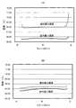
図13(A)は、上述した図12(A)の比較例に係るボート317の上、下段と中段のプロダクトウエハ上に形成された膜の面内膜厚を示した図であって、図13(B)は、図12(A)の比較例に係るボート317と、図12(B)の本実施形態に係るボート217を用いて上下段のプロダクトウエハ上に形成された膜の面内膜厚を比較して示した図である。 FIG. 13 (A) is a diagram showing the in-plane film thickness of the film formed on the upper, lower and middle product wafers of the boat 317 according to the comparative example of FIG. 12 (A) described above. 13 (B) is an in-plane film formed on the upper and lower product wafers using the boat 317 according to the comparative example of FIG. 12 (A) and the
図13(A)に示されているように、比較例に係るボート317を用いて成膜を行った場合には、図13(A)の破線で示すように、上下段のプロダクトウエハの両端部における膜厚が、プロダクトウエハの中心部における膜厚と比較して厚く形成されてしまい凹分布が大きくなり、均一性が悪化している。これは、モニタウエハの領域の未消費のラジカルが拡散して上方のプロダクトウエハの端部を増膜させているためであると考えられる。 As shown in FIG. 13 (A), when film thickness is formed using the boat 317 according to the comparative example, both ends of the upper and lower product wafers are shown by the broken line in FIG. 13 (A). The film thickness in the portion is formed thicker than the film thickness in the central portion of the product wafer, the concave distribution becomes large, and the uniformity is deteriorated. It is considered that this is because the unconsumed radicals in the region of the monitor wafer are diffused to thicken the upper end portion of the product wafer.
一方、図13(B)に示されているように、本実施形態に係るボート217を用いて成膜を行った場合には、図13(B)の実線で示すように、プロダクトウエハの端部における増膜が比較例に係るボート317を用いて成膜を行った場合と比較して抑制され、比較例に係るボート317を用いた場合と比較して均一性が改善されていることが確認された。 On the other hand, as shown in FIG. 13 (B), when the film is formed using the
図14(A)は、上述の図12(A)の比較例に係るボート317を用いて、プロダクトウエハ上に形成された膜の面間膜厚を示した図である。図14(B)は、上述の図12(B)の本実施形態に係るボート217を用いて、プロダクトウエハ上に形成された膜の面間膜厚を示した図である。 FIG. 14 (A) is a diagram showing the interplanetary film thickness of the film formed on the product wafer by using the boat 317 according to the comparative example of FIG. 12 (A) described above. FIG. 14 (B) is a diagram showing the interplanetary film thickness of the film formed on the product wafer using the
図14(A)に示されているように、比較例に係るボート317を用いて、大表面積のプロダクトウエハ上に形成された面内最大膜厚と、面内最小膜厚との差が上中下段において大きかった。特に、上段のプロダクトウエハ上に形成された面内最大膜厚と、面内最小膜厚との差が大きく、全体でみると、膜厚均一性は、8.0%だった。つまり、比較例に係るボート317を用いて大表面積のプロダクトウエハに成膜を行った場合には、面内の最大膜厚と最小膜厚との差が大きくなり、上段のプロダクトウエハに対しては、ローディング効果によってさらに悪化していることが確認された。 As shown in FIG. 14 (A), the difference between the in-plane maximum film thickness and the in-plane minimum film thickness formed on the product wafer having a large surface area by using the boat 317 according to the comparative example is higher. It was large in the middle and lower tiers. In particular, the difference between the maximum in-plane film thickness formed on the upper product wafer and the minimum in-plane film thickness was large, and the film thickness uniformity was 8.0% as a whole. That is, when a film is formed on a product wafer having a large surface area using the boat 317 according to the comparative example, the difference between the maximum in-plane film thickness and the minimum film thickness becomes large, and the upper product wafer is formed. Was confirmed to be further exacerbated by the loading effect.
一方、図14(B)に示されているように、本実施形態に係るボート217を用いて、大表面積のプロダクトウエハ上に形成された面内最大膜厚と、面内最小膜厚との差は、比較例に係るボート317を用いた場合と比較して小さかった。また、面内最大膜厚と面内最小膜厚との差は、上中下段のプロダクトウエハでほとんど変わらなかった。そして、全体でみると、膜厚均一性は、1.5%だった。つまり、比較例に係るボート317を用いた場合と比較して面間均一性も面内均一性も改善されていることが確認された。よって、ベアウエハの200倍の大表面積ウエハにも適用されることが確認された。 On the other hand, as shown in FIG. 14B, the maximum in-plane film thickness and the minimum in-plane film thickness formed on the product wafer having a large surface area by using the
(まとめ)
以上説明したように、基板処理装置10では、セパレートリング400が複数設けられたボート217を用いる。セパレートリング400が設けられたボート217を用いることにより、反応管203の内周面とセパレートリング400との間の隙間Gを小さくすることができる。これにより、ウエハ200上に平行な流れを形成し、上下方向の流れ及び拡散を抑制することができる。(Summary)
As described above, the
また、セパレートリング400が設けられたボート217を用いて、反応管203の内周面との隙間Gを小さくすることで、ウエハ200上への処理ガスの流入量を増加させ、面内均一性を向上させることができる。また、ウエハ200の上下方向の拡散が抑制されて、面間均一性を向上させることができる。 Further, by using the
また、セパレートリング400が設けられたボート217を用いて、反応管203の内周面との隙間Gを小さくすることで、供給スリット235a〜235cからのガスの90%以上を、ウエハ200の表面に対して平行に供給することが可能となる。言い換えれば、ウエハ200端部での上下方向への拡散を抑制することが可能となる。 Further, by using the
また、セパレートリング400は、中央が開口した形状とすることで、流路の厚みが広がり、ウエハ200上への流入量およびウエハ200上のガス流速を確保することができる。 Further, since the
また、セパレートリング400が設けられたボート217を用いて、反応管203の内周面との隙間Gを小さくすることで、ローディング効果を抑制することができる。 Further, the loading effect can be suppressed by reducing the gap G between the
また、セパレートリング400が一定の幅および厚みを有し、ウエハ200の裏面とウエハ200の下側のセパレートリング400の上面との間よりも小さな厚みを有するエンドエフェクタを用いることで、エンドエフェクタによるすくい上げの際にもセパレートリング400に干渉せずにそのまま移載を行うことができる。すなわち、セパレートリング400にエンドエフェクタを挿入する際にエンドエフェクタを通過させるための切り込みをセパレートリング400に設ける必要がない。 Further, by using an end effector in which the
また、セパレートリング400の外面とボート217の柱217aの外面が連続するよう構成されていることにより、ウエハ200を積層した際に半径方向に生じるウエハ200と反応管203の内周面との隙間を小さくすることができる。 Further, since the outer surface of the
また、一対のガスノズル340a、340cの噴射孔234a、234cから夫々噴射される不活性ガスの噴出方向と、ガスノズル340bの噴射孔234bから噴射される第2原料ガスの噴出方向とが実質的に平行になるように噴射孔234a、234b、234cが、ガスノズル340a、340b、340cに夫々形成されている。実質的に平行は、夫々の噴射方向がウエハの中心を向くように、平行からわずかに内向きに傾いた状態を含む。 Further, the ejection direction of the inert gas injected from the
これにより、第2原料ガスの流量等を制御することで、ウエハ200に形成される膜の厚さの面内ばらつきを抑制することができる。 As a result, in-plane variation in the thickness of the film formed on the
また、上下方向に並べられたウエハ200へのガスの供給量のばらつきも抑制され、形成される膜の厚さのウエハ間のばらつきを低減することができる。 Further, the variation in the amount of gas supplied to the
なお、本開示を特定の実施形態について詳細に説明したが、本開示は係る実施形態に限定されるものではなく、本開示の範囲内にて他の種々の実施形態をとることが可能であることは当業者にとって明らかである。 Although the present disclosure has been described in detail for a specific embodiment, the present disclosure is not limited to such an embodiment, and various other embodiments can be taken within the scope of the present disclosure. That is clear to those skilled in the art.
例えば、上述の実施形態では、上下方向に積載されたウエハ間にセパレートリング400が設ける構成について説明したが、これに限らず、セパレートリング400上にウエハ200を載置させてもよい。 For example, in the above-described embodiment, the configuration in which the
また、上記実施形態では、特に説明しなかったが、原料ガスとして、ハロシラン系ガス、例えば、SiおよびClを含むクロロシラン系ガスを用いることができる。また、クロロシラン系ガスは、Siソースとして作用する。クロロシラン系ガスとしては、例えば、ヘキサクロロジシラン(Si2Cl6、略称:HCDS)ガスを用いることができる。Further, in the above embodiment, although not particularly described, a chlorosilane-based gas, for example, a chlorosilane-based gas containing Si and Cl can be used as the raw material gas. Further, the chlorosilane-based gas acts as a Si source. As the chlorosilane-based gas, for example, hexachlorodisilane (Si2 Cl6 , abbreviation: HCDS) gas can be used.
原料ガスは、膜を構成する元素を含むものに限られず、他の原料ガスと反応するが構成元素を提供しないリアクタント(活性種、還元剤等とも称される)や触媒を含みうる。例えば、Si膜を形成するために第1原料ガスとして原子状水素を用いたり、W膜を形成するために第1原料ガスとしてジシラン(Si2H6)ガス、第2原料ガスとして六フッ化タングステン(WF6)ガスを用いたりすることができる。または反応ガスは、構成元素の提供の有無に関わらず、他の原料ガスと反応するものであればよい。The raw material gas is not limited to those containing the elements constituting the membrane, and may include reactors (also referred to as active species, reducing agents, etc.) and catalysts that react with other raw material gases but do not provide the constituent elements. For example, atomic hydrogen is used as the first raw material gas to form the Si film, disilane (Si2 H6 ) gas is used as the first raw material gas to form the W film, and hexafluoride is used as the second raw material gas. Tungsten (WF6 ) gas can be used. Alternatively, the reaction gas may be one that reacts with other raw material gases regardless of the presence or absence of the constituent elements provided.
(本開示の好ましい態様)
以下に、本開示の好ましい態様について付記する。
(付記1)
パターンが形成された複数のプロダクト基板と少なくとも1つのモニタ基板とを回転軸上に配列させて保持する基板保持具と、
少なくとも一部が、前記回転軸と同軸の円筒面によって構成された側面と、天井とを有し、前記側面と前記天井に囲まれた空間に前記基板保持具を収容する反応管と、
前記反応管を取り囲む炉体と、
前記反応管内で保持された基板のそれぞれに対応する流入口を有し、前記流入口から対応する基板の表面に対して平行にガスを供給するガス供給機構と、
前記基板のそれぞれの側方に面する流出口を有し、真空ポンプと流体的に連通し、前記基板の表面を流れたガスを排気するガス排気機構と、を備え、
前記基板保持具は、
前記基板の外径以下の内径を有し、回転軸上と直交する面に、前記回転軸と同心に、所定のピッチで配置される複数の円環状部材と、
前記複数の円環状部材の幅よりも狭い幅を有し、前記複数の円環状部材の外周と略一致する外接円に沿って配置され、前記複数の円環状部材を保持する複数の柱と、
前記複数の柱から、内周に向かって伸び、前記複数の円環状部材のそれぞれの間の位置で基板を載置する複数の支持部材と、を有し、
前記基板保持具が前記反応管内に収容されたときに、前記複数の円環状部材の外周と前記円筒面との間に、前記基板保持具の回転を可能な程度の狭い隙間が形成された基板処理装置。
(付記2)
付記1に記載の基板処理装置であって、
前記複数のプロダクト基板は200mm以上の直径を有し、前記狭い隙間は、プロダクト基板の直径の1%〜3%であり、前記ピッチは、プロダクト基板の直径の4%〜17%であり、前記複数の支持部材は、前記複数の円環状部材のそれぞれの間の略中央の位置で基板を載置する。
(付記3)
付記1に記載の基板処理装置であって、
前記反応管の側面は、全周が前記円筒面によって構成され、前記流入口と前記流出口は前記円筒面に対向して設けられ、
前記複数の柱は、多角柱であり、
前記複数の円環状部材は、平坦な平板であり、前記複数の柱との当接部分を除き一定の幅および厚みを有し、前記一定の幅は、5mm〜12mmであり、
前記ガス供給機構は、前記流入口からのガスの90%以上を、前記基板の表面に対して平行に供給する。
(付記4)
付記1に記載の基板処理装置であって、
前記炉体の筒部の内側を加熱するヒータと、
前記反応管の開口を塞ぐ蓋と、
前記蓋に設けられ、前記基板保持具を回動可能に保持する回転機構と、
前記蓋を、回転軸方向に移動させ、前記基板保持具の前記反応管への搬入及び搬出を行うエレベータと、
前記エレベータによって前記反応管外に取り出された前記基板保持具との間で、前記基板の移載を行う移載機と、
を有し、
前記移載機は、前記基板保持具へ挿入される部分であって、前記複数の支持部材に載置される基板の裏面と前記基板の下側の円環状部材の上面との間の距離よりも小さな厚みを有するエンドエフェクタを備え、前記エンドエフェクタは前記複数の支持部材に載置された基板を直接すくい上げることが可能に構成されている。
(付記5)
炉体に取り囲まれ、少なくとも一部が、回転軸と同軸の円筒面によって構成された側面と、天井とを有し、前記側面と前記天井に囲まれた空間を有する反応管内に、
基板の外径以下の内径を有し、回転軸上と直交する面に、前記回転軸と同心に、所定のピッチで配置される複数の円環状部材と、前記複数の円環状部材の幅よりも狭い幅を有し、前記複数の円環状部材の外周と略一致する外接円に沿って配置され、前記複数の円環状部材を保持する複数の柱と、前記複数の柱から、内周に向かって伸び、前記複数の円環状部材のそれぞれの間の位置で基板を載置する複数の支持部材と、を有する基板保持具によって、パターンが形成された複数のプロダクト基板と少なくとも1つのモニタ基板とを回転軸上に配列させて、前記複数の円環状部材の外周と前記円筒面との間に、前記基板保持具の回転を可能な程度の狭い隙間が形成された状態で収容する工程と、
前記反応管内で保持された基板のそれぞれに対応する流入口から、対応する基板の表面に対して平行にガスを供給する工程と、
真空ポンプと流体的に連通し、前記基板のそれぞれの側方に面する流出口から、前記基板の表面を流れたガスを排気する工程と、
を有する半導体装置の製造方法。
(付記6)
付記1に記載の基板処理装置であって、
前記流入口は、対応する基板の上面と略同じ高さに位置する下端と、対応する基板の直上の円環状部材の上面と同じかより高い高さに位置する上端と、を有する横長のスリット開口である。
(付記7)
付記3に記載の基板処理装置であって、
前記反応管は、前記円筒面を構成し、前記基板に直接面する内管と、前記内管の外側に広い隙間を隔てて設けられる、耐圧性を有する外管と、前記外管上に前記広い隙間と流体的に連通して設けられる排気ポートと、を備える。
(付記8)
付記3に記載の基板処理装置であって、
前記ガス供給機構は、処理ガスを前記回転軸に向けて吐出する処理ガス供給部と、処理ガス供給部の両側に設けられ、不活性ガスを基板の縁に沿って前記ガス排気機構へ向けて供給する1対の不活性ガス供給部と、を備える。(Preferable aspect of the present disclosure)
Hereinafter, preferred embodiments of the present disclosure will be added.
(Appendix 1)
A substrate holder for arranging and holding a plurality of patterned product substrates and at least one monitor substrate on a rotation axis.
A reaction tube having at least a part of a side surface formed of a cylindrical surface coaxial with the rotation axis and a ceiling, and accommodating the substrate holder in a space surrounded by the side surface and the ceiling.
The furnace body surrounding the reaction tube and
A gas supply mechanism having an inlet corresponding to each of the substrates held in the reaction tube and supplying gas from the inlet in parallel to the surface of the corresponding substrate.
It has an outlet facing each side of the substrate, and includes a gas exhaust mechanism that fluidly communicates with a vacuum pump and exhausts the gas that has flowed on the surface of the substrate.
The substrate holder is
A plurality of annular members having an inner diameter equal to or smaller than the outer diameter of the substrate and arranged at a predetermined pitch concentrically with the rotation axis on a surface orthogonal to the rotation axis.
A plurality of pillars having a width narrower than the width of the plurality of annular members, arranged along an circumscribed circle substantially matching the outer circumference of the plurality of annular members, and holding the plurality of annular members.
It has a plurality of support members extending from the plurality of columns toward the inner circumference and mounting a substrate at positions between the plurality of annular members.
When the substrate holder is housed in the reaction tube, a substrate is formed with a narrow gap capable of rotating the substrate holder between the outer circumferences of the plurality of annular members and the cylindrical surface. Processing equipment.
(Appendix 2)
The substrate processing apparatus according to
The plurality of product substrates have a diameter of 200 mm or more, the narrow gap is 1% to 3% of the diameter of the product substrate, and the pitch is 4% to 17% of the diameter of the product substrate. For the plurality of support members, the substrate is placed at a substantially central position between the plurality of annular members.
(Appendix 3)
The substrate processing apparatus according to
The entire circumference of the side surface of the reaction tube is formed by the cylindrical surface, and the inlet and the outlet are provided so as to face the cylindrical surface.
The plurality of pillars are polygonal pillars.
The plurality of annular members are flat flat plates, have a constant width and thickness except for contact portions with the plurality of columns, and the constant width is 5 mm to 12 mm.
The gas supply mechanism supplies 90% or more of the gas from the inflow port in parallel with the surface of the substrate.
(Appendix 4)
The substrate processing apparatus according to
A heater that heats the inside of the cylinder of the furnace body and
A lid that closes the opening of the reaction tube and
A rotating mechanism provided on the lid to rotatably hold the substrate holder,
An elevator that moves the lid in the direction of the rotation axis to carry in and out the substrate holder into and out of the reaction tube.
A transfer machine for transferring the substrate between the substrate holder taken out of the reaction tube by the elevator, and a transfer machine for transferring the substrate.
Have,
The transfer machine is a portion to be inserted into the substrate holder, and is based on the distance between the back surface of the substrate mounted on the plurality of support members and the upper surface of the annular member below the substrate. Also provided with an end effector having a small thickness, the end effector is configured to be able to directly scoop up a substrate mounted on the plurality of support members.
(Appendix 5)
In a reaction tube surrounded by a furnace body, at least in part, having a side surface formed of a cylindrical surface coaxial with the rotation axis and a ceiling, and having a space surrounded by the side surface and the ceiling.
From the width of a plurality of annular members having an inner diameter equal to or less than the outer diameter of the substrate and arranged concentrically with the rotation axis at a predetermined pitch on a surface orthogonal to the rotation axis, and the widths of the plurality of annular members. Also has a narrow width, is arranged along an circumscribed circle that substantially coincides with the outer circumference of the plurality of annular members, holds the plurality of annular members, and from the plurality of columns to the inner circumference. A plurality of product substrates and at least one monitor substrate in which a pattern is formed by a substrate holder having a plurality of support members extending toward each other and mounting the substrate at positions between the plurality of annular members. And are arranged on the rotation axis, and the step of accommodating the substrate holder in a state where a narrow gap is formed as much as possible between the outer periphery of the plurality of annular members and the cylindrical surface. ,
A step of supplying gas in parallel to the surface of the corresponding substrate from the inflow port corresponding to each of the substrates held in the reaction tube.
A process of fluidly communicating with a vacuum pump and exhausting gas flowing on the surface of the substrate from outlets facing each side of the substrate.
A method for manufacturing a semiconductor device having.
(Appendix 6)
The substrate processing apparatus according to
The inflow port is a horizontally long slit having a lower end located at substantially the same height as the upper surface of the corresponding substrate and an upper end located at the same height as or higher than the upper surface of the annular member directly above the corresponding substrate. It is an opening.
(Appendix 7)
The substrate processing apparatus according to Appendix 3.
The reaction tube constitutes the cylindrical surface, has an inner tube directly facing the substrate, a pressure-resistant outer tube provided on the outside of the inner tube with a wide gap, and the above-mentioned outer tube. It is provided with a wide gap and an exhaust port provided in fluid communication.
(Appendix 8)
The substrate processing apparatus according to Appendix 3.
The gas supply mechanism is provided on both sides of the processing gas supply unit that discharges the processing gas toward the rotating shaft and the processing gas supply unit, and directs the inert gas toward the gas exhaust mechanism along the edge of the substrate. It includes a pair of inert gas supply units to be supplied.
10 基板処理装置、
12 内管(管部材の一例)
18a 第一仕切(区画部材の一例)
18b 第二仕切(区画部材の一例)
18c 第三仕切(区画部材の一例)
18d 第四仕切(区画部材の一例)
20 外壁
200 ウエハ(基板の一例)
201 処理室
217 ボート(基板保持具の一例)
217a 柱
221 支持ピン(支持部材の一例)
222a 第一ノズル室(供給室の一例)
222b 第二ノズル室(供給室の一例)
222c 第三ノズル室(供給室の一例)
234a〜234c 噴射孔
235a〜 235c 供給スリット(供給孔の一例)
236 第一排気口(排出部の一例)
237 第二排気口(排出部の一例)
400 セパレートリング(円環状部材の一例)
400a 切欠き
10 Substrate processing equipment,
12 Inner pipe (an example of pipe member)
18a 1st partition (example of partition member)
18b Second partition (an example of partition member)
18c Third partition (an example of partition member)
18d 4th partition (example of partition member)
20
201
222a First nozzle chamber (example of supply chamber)
222b Second nozzle chamber (example of supply chamber)
222c Third nozzle chamber (example of supply chamber)
234a to
236 First exhaust port (an example of the exhaust part)
237 Second exhaust port (an example of the exhaust part)
400 separate ring (an example of an annular member)
400a notch
Claims (17)
Translated fromJapanese前記基板保持具を収容する反応管と、
前記反応管を取り囲む炉体と、
前記反応管内で保持された複数の基板のそれぞれに対応する複数の流入口を有し、前記複数の流入口から対応する基板の表面に対してそれぞれ平行にガスを供給するガス供給機構と、
前記複数の基板のそれぞれの側方に面する流出口を有し、真空ポンプと流体的に連通し、前記基板の表面を流れたガスを排気するガス排気機構と、を備え、
前記基板保持具は、
前記基板の外径以下の内径を有し、回転軸と直交する面に、前記回転軸と同心に、所定のピッチで配置される複数の円環状部材と、
前記複数の円環状部材の幅よりも狭い幅を有し、前記複数の円環状部材の外周と略一致する外接円に沿って配置され、前記複数の円環状部材を保持する複数の柱と、
前記複数の柱から、内周に向かって伸び、前記複数の円環状部材のそれぞれの間の位置で複数の基板をそれぞれ載置する複数の支持部材と、を有し、
前記基板保持具が前記反応管内に収容されたときに、前記複数の円環状部材の外周と前記反応管の側面との間に、前記基板保持具の回転を可能な隙間が形成され、
前記複数の流入口は、それぞれ、配列された複数の基板の隣接する2枚の基板間に配置され、対応する基板の真上の円環状部材の上面と同じかより高い位置の上端を有するスリット開口として形成された基板処理装置。A board holder that arranges and holdsmultiple boards on the axis of rotation,
A reaction tube that houses thepre-Symbol substrate holder,
The furnace body surrounding the reaction tube and
Aplurality of inlets corresponding to each of theplurality of substrates held by said reaction tube, a gas supply mechanism for supplying parallel to the gasrespectively to the surface of the corresponding substrate from theplurality of inlets,
It has an outlet facing each side of theplurality of substrates, and includes a gas exhaust mechanism that fluidly communicates with a vacuum pump and exhausts gas that has flowed on the surface of the substrate.
The substrate holder is
Has an inner diameter of not more than the outside diameter of the said substrate, the plane perpendicular tothe rotationalaxis, wherein the rotary shaft concentrically, the plurality of annular members disposed at a predetermined pitch,
A plurality of pillars having a width narrower than the width of the plurality of annular members, arranged along an circumscribed circle substantially matching the outer circumference of the plurality of annular members, and holding the plurality of annular members.
From said plurality of posts, extending toward the inner periphery, it has a plurality of support members for supportingaplurality of substrates at a position between each of said plurality of annular members,
When the substrate holder is accommodated in the reaction tube, between the outer and theside surfaceof the reaction tube of the plurality of annular members, betweenclearance as possible rotation of the substrate holder isformed,
The plurality of inlets are slits arranged between two adjacent substrates of the plurality of arranged substrates, each having an upper end at the same or higher position as the upper surface of the annular member directly above the corresponding substrate. A substrate processing deviceformed as an opening .
前記ガス供給機構は、前記複数の流入口の縦幅の中央部分に噴射孔がそれぞれ形成されたノズルを有する請求項1又は2に記載の基板処理装置。The substrate processing apparatus according to claim 1 or 2, wherein the gas supply mechanism has nozzles in which injection holes are formed in the central portions of the vertical widths of the plurality of inlets.
前記基板保持具を収容する反応管と、を備え、
前記基板保持具は、
前記基板の外径以下の内径を有し、回転軸と直交する面に、前記回転軸と同心に、所定のピッチで配置される複数の円環状部材と、
前記複数の円環状部材の幅よりも狭い幅を有し、前記複数の円環状部材の外周と略一致する外接円に沿って配置され、前記複数の円環状部材を保持する複数の柱と、
前記複数の柱から、内周に向かって伸び、前記複数の円環状部材のそれぞれの間の位置で複数の基板をそれぞれ載置する複数の支持部材と、を有し、
前記基板保持具が前記反応管内に収容されたときに、前記複数の円環状部材の外周と前記反応管の側面との間に、前記基板保持具の回転を可能な隙間が形成され、
前記複数の柱の内、前記基板を前記基板保持具内に搬送する際の搬送方向における手前側に設けられた柱に設けられた前記支持部材は、前記回転軸へ向かう方向よりも前記手前側に斜めに延出する基板処理装置。A board holder that arranges and holdsmultiple boards on the axis of rotation,
Anda reaction tube that houses thepre Symbol substrate holder,
The substrate holder is
Has an inner diameter of not more than the outside diameter of the said substrate, the plane perpendicular tothe rotationalaxis, wherein the rotary shaft concentrically, the plurality of annular members disposed at a predetermined pitch,
A plurality of pillars having a width narrower than the width of the plurality of annular members, arranged along an circumscribed circle substantially matching the outer circumference of the plurality of annular members, and holding the plurality of annular members.
From said plurality of posts, extending toward the inner periphery, it has a plurality of support members for supportingaplurality of substrates at a position between each of said plurality of annular members,
When the substrate holder is accommodated in the reaction tube, between the outer andthe side surface of the reaction tube of the plurality of annular members, betweenclearance as possible rotation of the substrate holder isformed,
Among the plurality of pillars, the support member provided on the pillar provided on the front side in the transport direction when the substrate is transported into the substrate holder is on the front side of the direction toward the rotation axis. A substrate processing devicethat extends diagonally .
前記複数の柱は、多角柱であり、
前記複数の円環状部材は、平坦な平板であり、前記複数の柱との当接部分を除き一定の幅および厚みを有し、前記一定の幅は、5mm〜12mmであり、
前記ガス供給機構は、前記流入口からのガスの90%以上を、前記基板の表面に対して平行に供給する、請求項1記載の基板処理装置。Side surface of the reaction tube, the entire circumference is formed bya circular cylindrical surface, said outlet and saidplurality of inlets are provided opposite to the cylindrical surface,
The plurality of pillars are polygonal pillars.
The plurality of annular members are flat flat plates, have a constant width and thickness except for contact portions with the plurality of columns, and the constant width is 5 mm to 12 mm.
The substrate processing apparatus according to claim 1, wherein the gas supply mechanism supplies 90% or more of the gas from the inflow port in parallel with the surface of the substrate.
前記反応管の開口を塞ぐ蓋と、
前記蓋に設けられ、前記基板保持具を回動可能に保持する回転機構と、
前記蓋を、回転軸方向に移動させ、前記基板保持具の前記反応管への搬入及び搬出を行うエレベータと、
前記エレベータによって前記反応管外に取り出された前記基板保持具との間で、前記基板の移載を行う移載機と、
を有し、
前記移載機は、前記基板保持具へ挿入される部分であって、前記複数の支持部材に載置される基板の裏面と前記基板の下側の円環状部材の上面との間の距離よりも小さな厚みを有するエンドエフェクタを備え、前記エンドエフェクタは前記複数の支持部材に載置された基板を直接すくい上げることが可能に構成された請求項1記載の基板処理装置。A heater that heats the inside of the cylinder of the furnace body and
A lid that closes the opening of the reaction tube and
A rotating mechanism provided on the lid to rotatably hold the substrate holder,
An elevator that moves the lid in the direction of the rotation axis to carry in and out the substrate holder into and out of the reaction tube.
A transfer machine for transferring the substrate between the substrate holder taken out of the reaction tube by the elevator, and a transfer machine for transferring the substrate.
Have,
The transfer machine is a portion to be inserted into the substrate holder, and is based on the distance between the back surface of the substrate mounted on the plurality of support members and the upper surface of the annular member below the substrate. The substrate processing apparatus according to claim 1, further comprising an end effector having a small thickness, wherein the end effector can directly scoop up a substrate mounted on the plurality of support members.
基板の外径以下の内径を有し、回転軸と直交する面に、前記回転軸と同心に、所定のピッチで配置される複数の円環状部材と、前記複数の円環状部材の幅よりも狭い幅を有し、前記複数の円環状部材の外周と略一致する外接円に沿って配置され、前記複数の円環状部材を保持する複数の柱と、前記複数の柱から、内周に向かって伸び、前記複数の円環状部材のそれぞれの間の位置で複数の基板をそれぞれ載置する複数の支持部材と、を有する基板保持具によって、複数の基板を回転軸上に配列させて、前記複数の円環状部材の外周と前記反応管の側面との間に、前記基板保持具の回転を可能な隙間が形成された状態で収容する工程と、
前記反応管内で保持された複数の基板のそれぞれに対応する複数の流入口から、対応する基板の表面に対してそれぞれ平行にガスを供給する工程と、
真空ポンプと流体的に連通し、前記複数の基板のそれぞれの側方に面する流出口から、前記基板の表面を流れたガスを排気する工程と、
を有し、
前記供給する工程では、それぞれ、配列された複数の基板の隣接する2枚の基板間に配置され、対応する基板の真上の円環状部材の上面と同じかより高い位置の上端を有するスリット開口として形成された前記複数の流入口が用いられる半導体装置の製造方法。Inthe reaction tube surrounded bythe furnace body,
Has an inner diameter of not more than the outside diameter of the substrate, the plane perpendicular tothe rotationalaxis, wherein the rotary shaft concentrically, the plurality of annular members disposed at a predetermined pitch, than the width of the plurality of annular members A plurality of columns having a narrow width and arranged along an circumscribed circle substantially coincide with the outer circumference of the plurality of annular members and holding the plurality of annular members, and the plurality of columns toward the inner circumference. elongation Te, wherein a plurality of support members foreach mountinga plurality of substrates at a position between each of the plurality of annular members, the substrate holder having, by arranging aplurality of substrates on a rotating shaft, wherein a step of accommodating between theside surface of the outer peripheral andthe reaction tube of the plurality of annular members, in a state in which among thepossible clearance rotation is formed of the substrate holder,
Aplurality of inlets corresponding to each of theplurality of substrates held in the reaction tube, and supplying in parallel to the gasrespectively to the surface of the corresponding substrate,
A process of fluidly communicating with a vacuum pump and exhausting gas flowing on the surface of the substrate from an outlet facing each side of theplurality of substrates.
Have a,
In the feeding step, each of the plurality of arranged substrates is arranged between two adjacent substrates, and has a slit opening having an upper end at a position equal to or higher than the upper surface of the annular member directly above the corresponding substrate. A method for manufacturing a semiconductor devicein which the plurality of inflow ports formed as above are used .
前記基板の外径以下の内径を有し、前記軸と直交する面に、前記軸と同心に、所定のピッチで配置される複数の円環状部材と、A plurality of annular members having an inner diameter equal to or smaller than the outer diameter of the substrate and arranged concentrically with the shaft at a predetermined pitch on a surface orthogonal to the shaft.
前記複数の円環状部材の幅よりも狭い幅を有し、前記複数の円環状部材の外周と略一致する外接円に沿って配置され、前記複数の円環状部材を保持する複数の柱と、A plurality of pillars having a width narrower than the width of the plurality of annular members, arranged along an circumscribed circle substantially matching the outer circumference of the plurality of annular members, and holding the plurality of annular members.
前記複数の柱から、内周に向かって伸び、前記複数の円環状部材のそれぞれの間の位置で複数の基板をそれぞれ載置する複数の支持部材と、を有し、It has a plurality of support members extending from the plurality of pillars toward the inner circumference and mounting a plurality of substrates at positions between the plurality of annular members.
前記複数の柱の内、前記基板を前記基板保持具に搬送する際の搬送方向における手前側に設けられた柱に設けられた前記支持部材は、前記軸へ向かう方向よりも前記手前側に斜めに延出する基板保持具。Among the plurality of pillars, the support member provided on the pillar provided on the front side in the transport direction when the substrate is transported to the substrate holder is oblique to the front side with respect to the direction toward the axis. Board holder that extends to.
前記反応管内で保持された複数の基板のそれぞれに対応する複数の流入口から、対応する基板の表面に対してそれぞれ平行にガスを供給する工程と、A step of supplying gas in parallel to the surface of the corresponding substrate from a plurality of inlets corresponding to each of the plurality of substrates held in the reaction tube.
真空ポンプと流体的に連通し、前記複数の基板のそれぞれの側方に面する流出口から、前記基板の表面を流れたガスを排気する工程と、A process of fluidly communicating with a vacuum pump and exhausting gas flowing on the surface of the substrate from an outlet facing each side of the plurality of substrates.
を有し、Have,
前記収容する工程では、前記複数の柱の内、前記基板を前記基板保持具に搬送する際の搬送方向における手前側に設けられた柱に設けられた前記支持部材が、前記回転軸へ向かう方向よりも前記手前側に斜めに延出した前記基板保持具が用いられる半導体装置の製造方法。In the accommodating step, among the plurality of pillars, the support member provided on the pillar provided on the front side in the transport direction when the substrate is transported to the substrate holder is directed toward the rotation axis. A method for manufacturing a semiconductor device in which the substrate holder extending diagonally toward the front side is used.
Priority Applications (7)
| Application Number | Priority Date | Filing Date | Title |
|---|---|---|---|
| JP2019147950AJP6770617B1 (en) | 2019-08-09 | 2019-08-09 | Substrate processing equipment, semiconductor device manufacturing method and substrate holder |
| CN202010711171.0ACN112349619A (en) | 2019-08-09 | 2020-07-22 | Substrate processing apparatus, method for manufacturing semiconductor device, substrate holder, and recording medium |
| TW109126420ATWI764225B (en) | 2019-08-09 | 2020-08-05 | Substrate processing apparatus, manufacturing method of semiconductor device, substrate holder, and program |
| TW111112733ATW202237894A (en) | 2019-08-09 | 2020-08-05 | Substrate processing apparatus, semiconductor element manufacturing method, substrate holder and recording medium |
| SG10202007550RASG10202007550RA (en) | 2019-08-09 | 2020-08-06 | Substrate processing apparatus, method of manufacturing semiconductor device, substrate holder, and program |
| KR1020200098725AKR20210018149A (en) | 2019-08-09 | 2020-08-06 | Substrate processing apparatus, method of manufacturing semiconductor device, substrate holder, and program |
| US16/988,363US20210043485A1 (en) | 2019-08-09 | 2020-08-07 | Substrate processing apparatus and substrate holder |
Applications Claiming Priority (1)
| Application Number | Priority Date | Filing Date | Title |
|---|---|---|---|
| JP2019147950AJP6770617B1 (en) | 2019-08-09 | 2019-08-09 | Substrate processing equipment, semiconductor device manufacturing method and substrate holder |
Related Child Applications (1)
| Application Number | Title | Priority Date | Filing Date |
|---|---|---|---|
| JP2020160988ADivisionJP7048690B2 (en) | 2020-09-25 | 2020-09-25 | Substrate processing equipment, semiconductor device manufacturing methods and substrate holders |
Publications (2)
| Publication Number | Publication Date |
|---|---|
| JP6770617B1true JP6770617B1 (en) | 2020-10-14 |
| JP2021028955A JP2021028955A (en) | 2021-02-25 |
Family
ID=72745200
Family Applications (1)
| Application Number | Title | Priority Date | Filing Date |
|---|---|---|---|
| JP2019147950AActiveJP6770617B1 (en) | 2019-08-09 | 2019-08-09 | Substrate processing equipment, semiconductor device manufacturing method and substrate holder |
Country Status (6)
| Country | Link |
|---|---|
| US (1) | US20210043485A1 (en) |
| JP (1) | JP6770617B1 (en) |
| KR (1) | KR20210018149A (en) |
| CN (1) | CN112349619A (en) |
| SG (1) | SG10202007550RA (en) |
| TW (2) | TWI764225B (en) |
Families Citing this family (10)
| Publication number | Priority date | Publication date | Assignee | Title |
|---|---|---|---|---|
| JP6915037B2 (en)* | 2017-02-27 | 2021-08-04 | ミライアル株式会社 | Board storage container |
| JP6894521B2 (en)* | 2017-09-25 | 2021-06-30 | 株式会社Kokusai Electric | Substrate processing equipment, quartz reaction tube, cleaning method and program |
| JP7175210B2 (en)* | 2019-02-04 | 2022-11-18 | 東京エレクトロン株式会社 | Exhaust device, treatment system and treatment method |
| KR102782608B1 (en)* | 2019-10-14 | 2025-03-14 | 삼성전자주식회사 | Semiconductor manufacturing apparatus |
| WO2022049675A1 (en)* | 2020-09-02 | 2022-03-10 | 株式会社Kokusai Electric | Substrate holder, substrate processing device, and method for manufacturing semiconductor device |
| CN115896747B (en)* | 2021-09-30 | 2024-10-15 | 馗鼎奈米科技(深圳)有限公司 | Surface treatment equipment |
| US12374569B2 (en)* | 2021-10-20 | 2025-07-29 | Yield Engineering Systems, Inc. | Batch processing oven for magnetic anneal |
| US12331400B2 (en) | 2022-11-07 | 2025-06-17 | Creating Nano Technologies, Inc. | Surface treatment apparatus |
| CN115558905B (en)* | 2022-12-01 | 2023-07-07 | 浙江晶越半导体有限公司 | Method and reactor for improving silicon carbide deposition rate and uniformity |
| CN119725131A (en)* | 2024-12-18 | 2025-03-28 | 浙江创芯集成电路有限公司 | Furnace tube monitoring equipment |
Family Cites Families (20)
| Publication number | Priority date | Publication date | Assignee | Title |
|---|---|---|---|---|
| JP2996355B2 (en)* | 1990-12-31 | 1999-12-27 | 株式会社福井信越石英 | Vertical storage jig |
| US6062853A (en)* | 1996-02-29 | 2000-05-16 | Tokyo Electron Limited | Heat-treating boat for semiconductor wafers |
| US6287112B1 (en)* | 2000-03-30 | 2001-09-11 | Asm International, N.V. | Wafer boat |
| JP3377996B1 (en)* | 2001-12-27 | 2003-02-17 | 東京エレクトロン株式会社 | Heat treatment boat and vertical heat treatment equipment |
| JP4506125B2 (en)* | 2003-07-16 | 2010-07-21 | 信越半導体株式会社 | Vertical boat for heat treatment and manufacturing method thereof |
| WO2005053016A1 (en) | 2003-11-27 | 2005-06-09 | Hitachi Kokusai Electric Inc. | Substrate treatment apparatus, substrate holding device, and semiconductor device manufacturing method |
| US20050287806A1 (en)* | 2004-06-24 | 2005-12-29 | Hiroyuki Matsuura | Vertical CVD apparatus and CVD method using the same |
| US7713355B2 (en)* | 2005-05-03 | 2010-05-11 | Integrated Materials, Incorporated | Silicon shelf towers |
| US7736436B2 (en)* | 2005-07-08 | 2010-06-15 | Integrated Materials, Incorporated | Detachable edge ring for thermal processing support towers |
| JP4426518B2 (en)* | 2005-10-11 | 2010-03-03 | 東京エレクトロン株式会社 | Processing equipment |
| JP5042950B2 (en)* | 2008-09-05 | 2012-10-03 | 東京エレクトロン株式会社 | Vertical heat treatment apparatus and substrate support |
| JP2010132958A (en) | 2008-12-03 | 2010-06-17 | Hitachi Kokusai Electric Inc | Substrate treatment apparatus |
| JP5356956B2 (en) | 2009-09-09 | 2013-12-04 | 株式会社日立国際電気 | Substrate processing apparatus, substrate processing method, and semiconductor device manufacturing method |
| JP2011165964A (en) | 2010-02-10 | 2011-08-25 | Hitachi Kokusai Electric Inc | Method of manufacturing semiconductor device |
| JP2011198957A (en) | 2010-03-18 | 2011-10-06 | Hitachi Kokusai Electric Inc | Substrate processing apparatus, substrate holder, and method of manufacturing semiconductor device |
| JP2015070046A (en)* | 2013-09-27 | 2015-04-13 | 株式会社日立国際電気 | Board holder |
| JP6468901B2 (en)* | 2015-03-19 | 2019-02-13 | 東京エレクトロン株式会社 | Substrate processing equipment |
| JP2016186991A (en)* | 2015-03-27 | 2016-10-27 | 株式会社日立国際電気 | Substrate processing apparatus, semiconductor device manufacturing method, and program |
| US10072892B2 (en)* | 2015-10-26 | 2018-09-11 | Globalwafers Co., Ltd. | Semiconductor wafer support ring for heat treatment |
| WO2018150615A1 (en)* | 2017-02-15 | 2018-08-23 | 株式会社Kokusai Electric | Substrate treatment device, reaction tube, method for manufacturing semiconductor device, and program |
- 2019
- 2019-08-09JPJP2019147950Apatent/JP6770617B1/enactiveActive
- 2020
- 2020-07-22CNCN202010711171.0Apatent/CN112349619A/enactivePending
- 2020-08-05TWTW109126420Apatent/TWI764225B/enactive
- 2020-08-05TWTW111112733Apatent/TW202237894A/enunknown
- 2020-08-06KRKR1020200098725Apatent/KR20210018149A/ennot_activeAbandoned
- 2020-08-06SGSG10202007550RApatent/SG10202007550RA/enunknown
- 2020-08-07USUS16/988,363patent/US20210043485A1/ennot_activeAbandoned
Also Published As
| Publication number | Publication date |
|---|---|
| SG10202007550RA (en) | 2021-03-30 |
| TW202237894A (en) | 2022-10-01 |
| TW202120741A (en) | 2021-06-01 |
| CN112349619A (en) | 2021-02-09 |
| JP2021028955A (en) | 2021-02-25 |
| KR20210018149A (en) | 2021-02-17 |
| TWI764225B (en) | 2022-05-11 |
| US20210043485A1 (en) | 2021-02-11 |
Similar Documents
| Publication | Publication Date | Title |
|---|---|---|
| JP6770617B1 (en) | Substrate processing equipment, semiconductor device manufacturing method and substrate holder | |
| JP6820816B2 (en) | Substrate processing equipment, reaction tubes, semiconductor equipment manufacturing methods, and programs | |
| US11555246B2 (en) | Substrate processing apparatus and method of manufacturing semiconductor device | |
| US10961625B2 (en) | Substrate processing apparatus, reaction tube and method of manufacturing semiconductor device | |
| JP2008258595A (en) | Substrate processing equipment | |
| JP2007109711A (en) | Processing apparatus, processing method, and storage medium | |
| JP7074790B2 (en) | Manufacturing method of substrate processing equipment and semiconductor equipment | |
| JP6867496B2 (en) | Substrate processing equipment, reaction tubes, substrate processing methods, and semiconductor device manufacturing methods | |
| JP7048690B2 (en) | Substrate processing equipment, semiconductor device manufacturing methods and substrate holders | |
| JP2008166321A (en) | Substrate processing apparatus and semiconductor device manufacturing method | |
| US20230116953A1 (en) | Substrate retainer, substrate processing apparatus and method of manufacturing semiconductor device | |
| JP7229266B2 (en) | SUBSTRATE PROCESSING APPARATUS, SEMICONDUCTOR DEVICE MANUFACTURING METHOD, AND PROGRAM | |
| JP4553263B2 (en) | Heat treatment apparatus and heat treatment method | |
| WO2025141995A1 (en) | Processing unit, substrate processing device, and method for manufacturing semiconductor device | |
| WO2025069289A1 (en) | Treatment container, treatment device, and method for manufacturing semiconductor device |
Legal Events
| Date | Code | Title | Description |
|---|---|---|---|
| A621 | Written request for application examination | Free format text:JAPANESE INTERMEDIATE CODE: A621 Effective date:20191202 | |
| A131 | Notification of reasons for refusal | Free format text:JAPANESE INTERMEDIATE CODE: A131 Effective date:20200327 | |
| A601 | Written request for extension of time | Free format text:JAPANESE INTERMEDIATE CODE: A601 Effective date:20200521 | |
| A521 | Request for written amendment filed | Free format text:JAPANESE INTERMEDIATE CODE: A523 Effective date:20200722 | |
| TRDD | Decision of grant or rejection written | ||
| A01 | Written decision to grant a patent or to grant a registration (utility model) | Free format text:JAPANESE INTERMEDIATE CODE: A01 Effective date:20200902 | |
| A61 | First payment of annual fees (during grant procedure) | Free format text:JAPANESE INTERMEDIATE CODE: A61 Effective date:20200925 | |
| R150 | Certificate of patent or registration of utility model | Ref document number:6770617 Country of ref document:JP Free format text:JAPANESE INTERMEDIATE CODE: R150 | |
| R250 | Receipt of annual fees | Free format text:JAPANESE INTERMEDIATE CODE: R250 | |
| R250 | Receipt of annual fees | Free format text:JAPANESE INTERMEDIATE CODE: R250 | |
| R250 | Receipt of annual fees | Free format text:JAPANESE INTERMEDIATE CODE: R250 |