JP6770103B2 - Finger tracking on input devices with proximity sensing - Google Patents
Finger tracking on input devices with proximity sensingDownload PDFInfo
- Publication number
- JP6770103B2 JP6770103B2JP2018567644AJP2018567644AJP6770103B2JP 6770103 B2JP6770103 B2JP 6770103B2JP 2018567644 AJP2018567644 AJP 2018567644AJP 2018567644 AJP2018567644 AJP 2018567644AJP 6770103 B2JP6770103 B2JP 6770103B2
- Authority
- JP
- Japan
- Prior art keywords
- user
- drive
- electrode
- hand
- touch
- Prior art date
- Legal status (The legal status is an assumption and is not a legal conclusion. Google has not performed a legal analysis and makes no representation as to the accuracy of the status listed.)
- Active
Links
Images


Classifications
- G—PHYSICS
- G06—COMPUTING OR CALCULATING; COUNTING
- G06F—ELECTRIC DIGITAL DATA PROCESSING
- G06F3/00—Input arrangements for transferring data to be processed into a form capable of being handled by the computer; Output arrangements for transferring data from processing unit to output unit, e.g. interface arrangements
- G06F3/01—Input arrangements or combined input and output arrangements for interaction between user and computer
- G06F3/03—Arrangements for converting the position or the displacement of a member into a coded form
- G06F3/041—Digitisers, e.g. for touch screens or touch pads, characterised by the transducing means
- G06F3/0416—Control or interface arrangements specially adapted for digitisers
- G—PHYSICS
- G06—COMPUTING OR CALCULATING; COUNTING
- G06F—ELECTRIC DIGITAL DATA PROCESSING
- G06F3/00—Input arrangements for transferring data to be processed into a form capable of being handled by the computer; Output arrangements for transferring data from processing unit to output unit, e.g. interface arrangements
- G06F3/01—Input arrangements or combined input and output arrangements for interaction between user and computer
- G06F3/03—Arrangements for converting the position or the displacement of a member into a coded form
- G06F3/041—Digitisers, e.g. for touch screens or touch pads, characterised by the transducing means
- G06F3/044—Digitisers, e.g. for touch screens or touch pads, characterised by the transducing means by capacitive means
- G06F3/0446—Digitisers, e.g. for touch screens or touch pads, characterised by the transducing means by capacitive means using a grid-like structure of electrodes in at least two directions, e.g. using row and column electrodes
- G—PHYSICS
- G06—COMPUTING OR CALCULATING; COUNTING
- G06F—ELECTRIC DIGITAL DATA PROCESSING
- G06F3/00—Input arrangements for transferring data to be processed into a form capable of being handled by the computer; Output arrangements for transferring data from processing unit to output unit, e.g. interface arrangements
- G06F3/01—Input arrangements or combined input and output arrangements for interaction between user and computer
- G06F3/03—Arrangements for converting the position or the displacement of a member into a coded form
- G06F3/041—Digitisers, e.g. for touch screens or touch pads, characterised by the transducing means
- G06F3/0412—Digitisers structurally integrated in a display
- G—PHYSICS
- G06—COMPUTING OR CALCULATING; COUNTING
- G06F—ELECTRIC DIGITAL DATA PROCESSING
- G06F3/00—Input arrangements for transferring data to be processed into a form capable of being handled by the computer; Output arrangements for transferring data from processing unit to output unit, e.g. interface arrangements
- G06F3/01—Input arrangements or combined input and output arrangements for interaction between user and computer
- G06F3/03—Arrangements for converting the position or the displacement of a member into a coded form
- G06F3/041—Digitisers, e.g. for touch screens or touch pads, characterised by the transducing means
- G06F3/044—Digitisers, e.g. for touch screens or touch pads, characterised by the transducing means by capacitive means
- G06F3/0444—Digitisers, e.g. for touch screens or touch pads, characterised by the transducing means by capacitive means using a single conductive element covering the whole sensing surface, e.g. by sensing the electrical current flowing at the corners
- G—PHYSICS
- G06—COMPUTING OR CALCULATING; COUNTING
- G06F—ELECTRIC DIGITAL DATA PROCESSING
- G06F2203/00—Indexing scheme relating to G06F3/00 - G06F3/048
- G06F2203/041—Indexing scheme relating to G06F3/041 - G06F3/045
- G06F2203/04101—2.5D-digitiser, i.e. digitiser detecting the X/Y position of the input means, finger or stylus, also when it does not touch, but is proximate to the digitiser's interaction surface and also measures the distance of the input means within a short range in the Z direction, possibly with a separate measurement setup
Landscapes
- Engineering & Computer Science (AREA)
- General Engineering & Computer Science (AREA)
- Theoretical Computer Science (AREA)
- Human Computer Interaction (AREA)
- Physics & Mathematics (AREA)
- General Physics & Mathematics (AREA)
- Position Input By Displaying (AREA)
- User Interface Of Digital Computer (AREA)
Description
Translated fromJapanese本発明は、一般に、タッチおよび近接センサに関する。より具体的には、本発明は、タッチおよび近接感知デバイスを握っている指の追跡を改良する機能に関する。 The present invention generally relates to touch and proximity sensors. More specifically, the present invention relates to a function that improves tracking of a finger holding a touch and proximity sensing device.
本発明で使用され得る静電容量性流量センサにはいくつかの設計がある。任意の静電容量感知タッチパッドがどのようにして本発明を活用できるのかをより良く理解するために、タッチセンサの基礎技術を検討することは有用である。 There are several designs for capacitive flow sensors that can be used in the present invention. It is useful to study the basic techniques of touch sensors in order to better understand how any capacitive touch pad can utilize the present invention.
CIRQUE(R)社製のタッチパッドは、相互静電容量感知デバイスであり、その一例が、図1にブロック図として例示されている。このタッチパッド10では、X(12)およびY(14)電極の格子と、感知電極16とが、タッチパッドのタッチ感知領域18を画定するために使用される。典型的には、タッチパッド10は、約16×12の電極、またはスペースの制約がある場合は8×6の電極からなる矩形格子である。これらX(12)およびY(14)(すなわち、行および列)電極には、単一の感知電極16がインターレースしている。すべての位置測定は、感知電極16によって行われる。 The touch pad manufactured by CIRQUE (R) is a mutual capacitance sensing device, and an example thereof is illustrated as a block diagram in FIG. In the
CIRQUE(R)社製のタッチパッド10は、感知線16上の電荷の不均衡を測定する。タッチパッド10上または近傍にポインティングオブジェクトがない場合、タッチパッド回路20は均衡状態にあり、感知線16上に電荷の不均衡はない。オブジェクトがタッチ面(タッチパッド10の感知領域18)にアプローチまたはタッチしたときの静電容量結合によって、ポインティングオブジェクトが不均衡を生成すると、電極12、14に静電容量の変化が生じる。測定されるものは静電容量の変化であるが、電極12、14上の絶対的な静電容量値ではない。タッチパッド10は、感知線上の電荷の均衡を再確立または復元するために感知線16に注入されねばならない電荷量を測定することによって、静電容量の変化を決定する。 The
上記のシステムを利用して、以下のようにタッチパッド10上またはその近傍の指の位置を決定する。この例は行電極12について説明しており、列電極14についても同様に繰り返される。行電極および列電極の測定値から取得される値は、タッチパッド10上またはそれに近接したポインティングオブジェクトの重心である交差点を決定する。 Using the above system, the position of the finger on or near the
第1のステップでは、第1の組の行電極12が、P、N生成器22からの第1の信号で駆動され、異なるが隣接する第2の組の行電極が、P、N生成器からの第2の信号で駆動される。タッチパッド回路20は、どの行電極がポインティングオブジェクトに最も近いかを示す相互静電容量測定デバイス26を使用して、感知線16から値を取得する。しかしながら、あるマイクロコントローラ28の制御下にあるタッチパッド回路20は、ポインティングオブジェクトが行電極のどちら側に位置しているのかをまだ決定できず、またこのタッチパッド回路20は、ポインティングオブジェクトが電極からどれだけ離れて位置しているのかを決定できない。したがって、このシステムは、駆動されるべき電極12のグループを、1つの電極分だけシフトさせる。言い換えれば、グループの一方の側の電極が追加され、グループの反対側の電極はもはや駆動されない。その後、新たなグループは、P、N生成器22によって駆動され、感知線16の第2の測定値が獲得される。 In the first step, the first set of
これら2つの測定値から、行電極のどちら側にポインティングオブジェクトが位置しているか、およびどれだけ離れているかを決定することが可能である。その後、測定された2つの信号の大きさを比較する式を使用して、ポインティングオブジェクト位置の決定を実行する。 From these two measurements, it is possible to determine on which side of the row electrode the pointing object is located and how far apart. The pointing object position is then determined using an equation that compares the magnitudes of the two measured signals.
CIRQUE(R)社製のタッチパッドの感度または解像度は、16×12格子の行および列電極が示唆するよりもはるかに高い。解像度は通常1インチあたり960カウント、またはそれ以上のオーダである。正確な解像度は、構成要素の感度、同じ行および列上の電極12、14間の間隔、および本発明にとって重要ではない他の要因によって決定される。P、N生成器24を使用して、Yすなわち列電極14に対して上記のプロセスが繰り返される。 The sensitivity or resolution of the CIRQUE (R) touchpad is much higher than the 16x12 grid row and column electrodes suggest. The resolution is usually on the order of 960 counts per inch or more. The exact resolution is determined by the sensitivity of the components, the spacing between the
上述したCIRQUE(R)製タッチパッドは、XおよびY電極12、14の格子と、個別の単一の感知電極16とを使用するが、感知電極は実際には多重化を使用することによってXまたはY電極12、14とすることができる。 The CIRQUE (R) touchpad described above uses a grid of X and
近年、ハンドヘルドまたはポータブル電子デバイスが普及している。これらデバイスには、スマートフォン、ビデオゲームコントローラ、ポータブルビデオゲーム、テレビリモコン、カメラ、拡張現実メガネ、仮想現実メガネ、マルチメディアプレーヤなどが含まれるが、これらに限定されない。 In recent years, handheld or portable electronic devices have become widespread. These devices include, but are not limited to, smartphones, video game controllers, portable video games, TV remote controls, cameras, augmented reality glasses, virtual reality glasses, multimedia players, and the like.
ポータブル電子機器と対話する新たな方法を提供することによって、能力を向上させる動向がある。1つの課題は、直感的で効率的なユーザ入力を作成することである。1つの特定の例は、タッチパネル、タッチスクリーン、タッチパッド、タッチ面またはタッチセンサと接触させた状態だけでなく、三次元空間内で指を追跡したいという要望である。 There is a trend to improve capabilities by providing new ways to interact with portable electronics. One challenge is to create intuitive and efficient user input. One particular example is the desire to track a finger in three-dimensional space as well as in contact with a touch panel, touch screen, touch pad, touch surface or touch sensor.
典型的な静電容量式タッチセンサは、相互静電容量モードまたは自己静電容量モードで動作する。相互静電容量モードでは、駆動電極などの少なくとも1つの電極は、変化する電圧で、および信号を感知する感知電極のような少なくとも別の電極とともに、駆動され得る。指または他の導電性のオブジェクトが、同一平面上のXおよびY電極格子の送信電極(駆動電極)と受信電極(感知電極)との間の接合部に接近すると、ポインティングオブジェクトが接地しているときは駆動電極と感知電極との間の信号結合は減少するか、または、ポインティングオブジェクトが電気的にフロートしている小さなオブジェクトである場合は信号結合が増加され得る。 A typical capacitive touch sensor operates in mutual capacitive mode or self-capacitive mode. In mutual capacitance mode, at least one electrode, such as a driving electrode, can be driven at a changing voltage and along with at least another electrode, such as a sensing electrode that senses a signal. When a finger or other conductive object approaches the junction between the transmitting and receiving electrodes (sensing electrodes) of the coplanar X and Y electrode grids, the pointing object is grounded. Sometimes the signal coupling between the driving electrode and the sensing electrode can be reduced, or the signal coupling can be increased if the pointing object is a small object that is electrically floating.
自己静電容量モードでは、感知電極の静電容量負荷が測定されている間に、少なくとも1つの電極が変化する電圧で駆動される。接地された導電性オブジェクトが、X電極およびY電極に接近すると、感知電極における静電容量性負荷が増大する。相互静電容量法と自己静電容量法は両方とも、比較的短い距離におけるオブジェクト検出に限定され得る。 In self-capacitive mode, at least one electrode is driven by a varying voltage while the capacitive load of the sensing electrodes is being measured. As the grounded conductive object approaches the X and Y electrodes, the capacitive load on the sensing electrode increases. Both the mutual capacitance method and the self-capacitance method can be limited to object detection at relatively short distances.
第1の実施形態では、本発明は、少なくとも片手でタッチセンサを握っているユーザに時間変化する電圧または駆動信号を駆動し、その後、指が、タッチセンサ内の感知電極の近接感知距離内にある場合、タッチセンサ上にある感知電極上のユーザの指または親指からの駆動信号を感知することによって、タッチおよび近接感知タッチセンサの近接感知距離を増加させ、これによって、タッチセンサの近接感知モードにおける、ユーザのより長い距離の検出可能性を有効にするためのシステムおよび方法である。 In a first embodiment, the invention drives a time-varying voltage or drive signal to a user holding the touch sensor with at least one hand, after which the finger is within the proximity sensing distance of the sensing electrodes in the touch sensor. In some cases, the proximity sensing distance of the touch and proximity sensing touch sensor is increased by sensing the drive signal from the user's finger or thumb on the sensing electrode on the touch sensor, thereby the proximity sensing mode of the touch sensor. A system and method for enabling a user's longer range detectability in.
本発明のこれらおよび他の目的、特徴、利点および代替の態様は、添付の図面と併せた以下の詳細説明の考察から当業者に明らかになるであろう。 These and other objects, features, advantages and alternative aspects of the invention will become apparent to those skilled in the art from the discussion of the following detailed description in conjunction with the accompanying drawings.
本発明の様々な要素に数字指定が与えられ、当業者が本発明を製作し使用することを可能にするように本発明が論議される図面に参照がなされる。以下の説明は本発明の原理の単なる例示であり、以下に続く特許請求の範囲を狭めるものと見なされるべきではないことが理解されるべきである。 Numerical designations are given to the various elements of the invention and references are made to the drawings in which the invention is discussed to allow one of ordinary skill in the art to make and use the invention. It should be understood that the following description is merely an example of the principles of the invention and should not be considered to narrow the scope of the claims that follow.
第1の実施形態は、検出可能なオブジェクトのより長い検出距離を可能にするために、タッチおよび近接感知デバイス(以下、「タッチセンサ」)の近接感知距離を増加させることが対象とされ得る。第1の実施形態はまた、タッチセンサの新たな応用を可能にし得る。 A first embodiment may be directed to increasing the proximity sensing distance of a touch and proximity sensing device (“touch sensor”) to allow for a longer detection distance of a detectable object. The first embodiment may also enable new applications for touch sensors.
図2は、第1の実施形態の概念のブロック図である。図2は、少なくとも1つの検出可能なオブジェクト32と、少なくとも1つの感知電極34と、駆動信号生成器36と、感知回路38と、電源50とから構成されるタッチセンサ30を図示する。電源は、駆動信号生成器36と感知回路38との両方にエネルギーを供給する。少なくとも1つの検出可能なオブジェクト32と感知電極34とが互いに隣接するように図示されている。しかしながら、この物理的関係は例示目的のみのためであり、第1の実施形態の限定要因ではない。説明されるように、ユーザが、少なくとも1つの駆動電極32上の信号を拡張したものとなるように、駆動電極は何らかの手法でユーザに結合されなければならない。 FIG. 2 is a block diagram of the concept of the first embodiment. FIG. 2 illustrates a
複数の感知電極34が存在し得、それらのすべてが第1の実施形態の動作を変える訳ではないことが理解されるべきである。言い換えれば、複数の感知電極34は、タッチセンサ40がどのように動作し得るかを変えることはない。しかしながら、複数の感知電極34は、少なくとも1つの駆動電極32が、タッチセンサ30の少なくとも1つの感知電極34によって検出可能であり得るスペースの容積を増加させ得る。 It should be understood that there may be
少なくとも1つの駆動電極32は、矩形のオブジェクトとして図示されているが、少なくとも1つの検出可能なオブジェクトは、任意の形状を有し得、また多数の突起を有し得る。たとえば、少なくとも1つの駆動電極32は、複数の指および親指でユーザの手に結合されている電極であり得る。実質的に、ユーザの手が駆動電極32になる。 The at least one
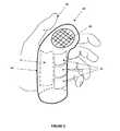
第1の実施形態がどのように実施され得るかの例示は、図3に図示されるようなハンドヘルドタッチセンサ40におけるものである。図3は、ユーザの手42によって握られ得るオブジェクトのための筐体から構成されるタッチセンサ40を図示する。たとえば、タッチセンサ40は、ユーザの手42の指および親指が、タッチセンサ40上のあらかじめ決定された場所に置かれることを可能にする人間工学的に心地良いグリップを有するオブジェクトであってよい。 An example of how the first embodiment can be implemented is in the
これらのあらかじめ決定された場所は、タッチセンサとして機能し得るオブジェクトを握っている手42のための自然な置き場であり得る。この例では、タッチセンサ40は、図3に図示されるように、実質的に円筒形の形状であり得る。タッチセンサ40は、タッチセンサ40上の様々な場所に配置された複数のタッチセンサパッド46を有する実質的な円筒形本体44を有し得る。 These predetermined locations can be natural storage for the
タッチセンサ40の筐体上のタッチセンサパッド46の場所は、ユーザがタッチセンサ40を握っている場合にタッチする可能性がある場所、またはタッチセンサと対話するためにユーザがタッチする必要がある場所のいずれかであり得る。 The location of the
たとえば、円筒形本体に配置されたタッチセンサパッド46は、ユーザがタッチセンサをこれから使用することを示唆するような形で、ユーザがタッチセンサ40を握っているときに手のひらや指先が置かれる可能性がある場所に配置され得る。しかしながら、この例では、タッチセンサディスプレイまたはタッチスクリーン48は、円筒形本体44の端部に配置されてもよい。タッチセンサ40の円筒形本体44上に、1つまたは複数のタッチスクリーンが存在し得る。この例では、タッチスクリーン48は、他のタッチセンサパッド46よりも大きくても小さくてもよく、ユーザの親指の存在だけでなく、親指の場所および動きを追跡できてもよい。したがって、より小さなタッチセンサパッド46は、検出可能なオブジェクトの存在またはアプローチを検出するためにのみ使用され得、他のタッチスクリーン48は、検出および追跡が実行される、当業者に知られているタッチセンサのような、より多くの能力を有し、より多くの機能を提供し得る。 For example, the
第1の実施形態は、ユーザの手、指、および親指の存在または場所を検出するタッチセンサパッド46およびタッチスクリーン48を含むのみならず、タッチセンサ30によって検出可能な信号をユーザに駆動するためのシステムも含み得る。 A first embodiment includes a
第1の実施形態では、駆動信号生成器36は、タッチセンサ40を握っているユーザに時間変化する電圧(「駆動信号」または「信号」)を駆動し、その後、駆動信号から、ユーザの指または親指に存在し得る結合電圧を感知し得る。この信号は、タッチセンサ40のタッチセンサパッド46およびタッチスクリーン48上で検出可能であり得る。したがって、タッチセンサパッド46およびタッチスクリーン48は、感知電極34を介して、タッチセンサ40内に配置された感知回路38に結合され得る。感知回路38は、タッチセンサ40内に配置されている剛性または可撓性の回路基板上に配置され得るか、またはタッチセンサ自体の筐体上にさえも配置され得る。 In the first embodiment, the
タッチセンサ40は、駆動信号生成器36および感知回路38に電力を提供するための電源を含み得る。この第1の実施形態では、駆動信号生成器36、感知回路38、電源50、少なくとも1つの駆動電極32、および少なくとも1つの感知電極34はすべて、タッチセンサ40内に配置され得る。 The
本発明の第1の実施形態では、少なくとも1つの駆動電極が、ユーザへの直接的なガルバニック接続を形成し得る。たとえば、これは、手のようなユーザの皮膚と直接接触するタッチセンサ40の、筐体上に露出された駆動電極導体52を駆動することによって行われ得る。たとえば、図3において隠線を使用して図示されている大きな手のひら導体52は、ユーザへの駆動電極32の接続であり得る。 In the first embodiment of the invention, at least one drive electrode may form a direct galvanic connection to the user. For example, this can be done by driving a
代替的に、この接続は、直接の接触でなくともよい。たとえば、少なくとも1つの駆動電極32は、タッチセンサ40内を起点としてもよいが、ユーザに結合されるために、タッチセンサの筐体を超えて延在してもよいことが注目される。たとえば、駆動電極32は、静電容量性接続の形態であり得る。 Alternatively, this connection does not have to be a direct contact. For example, it is noted that at least one
静電容量性接続を形成する1つの手法は、十分大きな駆動信号がユーザに伝達され得るように、駆動電極32が十分大きな表面積を有し、ユーザのある部分に十分近くなるようにすることであり得る。たとえば、約12平方センチメートルで、ユーザの手まで約1mmの距離にあるタッチセンサ40内の金属板は、十分大きな信号をユーザに静電容量結合するのに適切であり得るが、これよりも大きいまたは小さい金属板であってもよい。金属板は、タッチセンサ40の筐体の内側にあっても外側にあってもよい。 One technique for forming a capacitive connection is to ensure that the
図4に図示される別の代替実施形態では、駆動電極32は、駆動電極32を含む可撓性ストラップ54の一部であることによってユーザと接触することができる。駆動電極32は、第1の端部で、タッチセンサ40の筐体内の駆動信号生成器36に結合され、第2の端部で、ユーザの手または手首の周りを包み得るストラップ54に結合され得る。 In another alternative embodiment illustrated in FIG. 4, the
駆動電極32は、金属、有機材料、または無機化合物であり得る。駆動電極32はまた、可撓性または剛性であり得る。重要なことは、駆動電極32が、ユーザと静電容量結合されるか、または直接接触することである。 The
本発明の別の態様では、ハンドヘルドタッチセンサ40は、通常、アースから電気的に絶縁されていてもよく、電源50でバッテリ駆動されていてもよい。これらの理由のために、ハンドヘルドタッチセンサを握っているユーザに結合されている駆動電極32は、電圧基準となることができ、またその結果、電源およびそれにガルバニックに接続されている可能性のある構成要素を変調させ得る。 In another aspect of the invention, the
別の実施形態では、タッチセンサ40の電源50は、充電器またはUSB接続のような外部接地基準に結合され得る。この場合、ユーザは依然として電圧で駆動され得るが、ハンドヘルドタッチセンサ40の接地基準は変調されていない。 In another embodiment, the
第1の実施形態は、図3および図4に図示される特徴も含み得る。これらの図は、タッチスクリーン48が、タッチスクリーン48から、タッチセンサ40を保持しているユーザに視覚的なフィードバックを提供するのみならず、入力をも提供し得ることを図示している。 The first embodiment may also include the features illustrated in FIGS. 3 and 4. These figures illustrate that the
タッチセンサ40はまた、指が近接距離内に入った場合、またはタッチによって、アクティブ化および非アクティブ化され得る静電容量感知領域であるタッチスクリーン48上の仮想ボタンを含み得、これはボタンと称され得る。さらに、タッチスクリーン48上の仮想ボタンの場所は、タッチスクリーン48上に図示されているものに応じて、異なる機能を提供するために変更され得る。 The
本発明のすべての実施形態において、本発明は、ユーザの指または親指などの検出可能なオブジェクトがタッチセンサ40によって検出可能である距離を実質的に増加させ得る。この能力は、指がタッチスクリーン48に近づいた場合、タッチスクリーン48上の仮想ボタンの周囲の領域を照らすなどの機能をタッチセンサ40に追加するのに有用であり得る。 In all embodiments of the invention, the invention can substantially increase the distance at which a detectable object, such as a user's finger or thumb, can be detected by the
本発明の実施形態の別の用途は、タッチセンサへの他の入力をトリガすることなく、タッチセンサ40上でホバリングしている、またはタッチセンサ40に向かって移動している指の場所を、タッチセンサ40上に示すことであり得る。言い換えれば、タッチセンサパッド46またはタッチスクリーン48への検出可能なオブジェクトのアプローチは、指が特定のタッチセンサパッド46、または、タッチセンサのタッチスクリーン48にアプローチしているといういくつかの視覚的、触覚的、または聴覚的フィードバックを、タッチセンサ40のある部分に、ユーザへ与えさせることができる。 Another use of an embodiment of the invention is to locate a finger hovering over or moving towards the
本発明の別の態様は、タッチセンサ40が、当業者に一般的な方式で動作するXおよびY電極の駆動および感知格子を有する典型的な最新技術のタッチセンサであってよいことであり得る。しかしながら、別の代替実施形態では、タッチセンサ40は、すべての電極が駆動電極32または感知電極34になるように電極の機能を変更することができる。したがって、駆動信号は、タッチセンサ40以外のデバイスから来ることがあるが、それでもなおタッチセンサによって検出可能であり得る。 Another aspect of the invention may be that the
図5は、本発明の別の実施形態において、タッチセンサおよび近接センサの機能が単一のタッチおよび近接感知デバイス60において分離され得ることをブロック図で図示する。本発明のこの実施形態では、2つの駆動信号生成器および別々の駆動電極および感知電極、タッチセンサ62として動作するデバイスの一部分のための1つの駆動信号生成器、および近接センサ64として動作しているデバイス60の一部分のための異なる駆動信号生成器および駆動電極および感知電極とが存在し得る。 FIG. 5 is a block diagram illustrating that in another embodiment of the invention, the functions of the touch sensor and proximity sensor can be separated in a single touch and
本発明の実施形態の応用は、ユーザが自分の手を直接見ることができない仮想現実(VR)システム、または、ユーザが見ることができるが、視覚が使用される場合であってもARと対話するためのより多くの手法を必要とする拡張現実システムにおけるものであり得る。 Applications of embodiments of the present invention are virtual reality (VR) systems in which the user cannot directly see his or her hands, or interact with AR even when the user can see but vision is used. It can be in an augmented reality system that requires more techniques to do.
VRシステムでは、ユーザの中には自分の手が見えない場合に、ハンドヘルドゲームコントローラ上の特定のボタンを見つけるのに困ることがあり得る。本発明の実施形態は、ユーザが正しいボタンまたはコントロールにタッチすることができるように、ハンドヘルドタッチセンサのタッチ面上の自身の指の場所を、VRシステムがユーザに示すことを可能にすることができる。これはまた、VR内のオブジェクトの把握、ポインティング、可変トリガアクション、可変スクイージング、フリック、フィストクリンチなどのVRアクションのためにも使用され得る。 In a VR system, it can be difficult to find a particular button on a handheld game controller when some users cannot see their hands. Embodiments of the present invention may allow the VR system to indicate to the user the location of his or her finger on the touch surface of the handheld touch sensor so that the user can touch the correct button or control. it can. It can also be used for VR actions such as grasping objects in VR, pointing, variable trigger actions, variable squeezing, flicking, fist clinch and so on.
これらの機能はすべてVRにおいて役立つが、ARにおいても役立つ。仮想オブジェクトと現実オブジェクトとを組み合わせ、それらをスマートフォンのディスプレイまたはARメガネのレンズのようなディスプレイ上で組み合わせることができるスマートフォンまたはメガネのようなARデバイスを考察する。 All of these features are useful in VR, but also in AR. Consider an AR device such as a smartphone or glasses that can combine virtual and real objects and combine them on a smartphone display or a display such as the lens of AR glasses.
本発明の1つの実施形態では、スマートフォンまたはメガネのようなデバイスが、個別のハンドヘルドタッチセンサ40によって検出可能な駆動信号を生成してもよく、またはハンドヘルドタッチセンサが、スマートフォンまたはメガネによって検出可能な駆動信号を生成してもよい。 In one embodiment of the invention, a device such as a smartphone or glasses may generate a drive signal detectable by a separate
上記の実施形態は、本発明のハンドヘルドデバイスの応用を説明したが、他のものも可能である。別の実施形態では、駆動電極は、車両の座席にある。この応用では、多数の駆動電極が、多数のシートにて同じタッチ感知電極において使用され得る。この場合、デバイスと対話している異なるユーザを区別するために、駆動電極が使用され得る。これは、運転者および交替運転者の認識が望まれる自動車応用において特に有用であり得る。 The above embodiments have described applications of the handheld devices of the present invention, but others are also possible. In another embodiment, the drive electrode is on the vehicle seat. In this application, multiple drive electrodes can be used in the same touch-sensitive electrode on multiple sheets. In this case, drive electrodes may be used to distinguish between different users interacting with the device. This can be particularly useful in automotive applications where driver and alternation driver awareness is desired.
要約すると、本発明の第1の実施形態の最も基本的な形態は以下の通りである。第1の実施形態は、タッチおよび近接センサの近接感知距離を増加させるためのシステムであり、このシステムは、タッチおよび近接センサシステムのための筐体と、電源と、駆動信号を生成するための駆動信号生成器と、駆動信号生成器から駆動信号を受信するための少なくとも1つの駆動電極と、少なくとも1つの駆動電極からの駆動信号に間接的に静電容量結合される少なくとも1つの感知電極と、少なくとも1つの感知電極において静電容量結合された駆動信号を受信するための感知回路と、少なくとも駆動電極からの駆動信号を受信する検出可能なオブジェクトとから構成され、少なくとも1つの感知電極は、検出可能なオブジェクト上の駆動電極を検出し、これによって、駆動電極からの駆動信号を間接的に検出し、検出可能なオブジェクトは、検出可能なオブジェクトが駆動信号を受信しなかった場合よりも長い距離において、感知回路によって検出可能である。 In summary, the most basic embodiments of the first embodiment of the present invention are as follows. The first embodiment is a system for increasing the proximity sensing distance of the touch and proximity sensors, which system is for generating a housing for the touch and proximity sensor system, a power source, and a drive signal. A drive signal generator, at least one drive electrode for receiving a drive signal from the drive signal generator, and at least one sensing electrode indirectly capacitively coupled to a drive signal from at least one drive electrode. The at least one sensing electrode is composed of a sensing circuit for receiving a electrostatically coupled drive signal at at least one sensing electrode and a detectable object that receives at least a driving signal from the driving electrode. It detects the drive electrode on the detectable object, thereby indirectly detecting the drive signal from the drive electrode, and the detectable object is longer than if the detectable object did not receive the drive signal. At a distance, it can be detected by a sensing circuit.
同様に、第1の実施形態の方法は、同じシステムを提供し、その後、少なくとも1つの駆動電極において駆動信号を生成し、少なくとも1つの駆動電極から、検出可能なオブジェクトへ駆動信号を伝達し、検出可能なオブジェクトにおける駆動信号を少なくとも1つの感知電極へ静電容量結合し、感知回路を使用して、検出可能なオブジェクトを検出するものであり、検出可能なオブジェクトは、検出可能なオブジェクトが駆動信号を受信しなかった場合よりも長い距離において、感知回路によって検出可能である。 Similarly, the method of the first embodiment provides the same system, after which a drive signal is generated at at least one drive electrode and the drive signal is transmitted from at least one drive electrode to a detectable object. The drive signal in the detectable object is electrostatically coupled to at least one sensing electrode and a sensing circuit is used to detect the detectable object, which is driven by the detectable object. It can be detected by the sensing circuit at a longer distance than if no signal was received.
いくつかの例示的な実施形態のみが上記に詳細に説明されたが、当業者は、本発明から実質的に逸脱することなく、例示的な実施形態において多くの修正が可能であることを容易に認識するであろう。したがって、そのようなすべての修正は、以下の特許請求の範囲に定義される本開示の範囲内に含まれることが意図される。出願人の明示的な意図は、特許請求の範囲が、関連付けられた機能とともに「means for」という文言を明示的に使用する場合を除いて、ここにおける特許請求の範囲のいずれかのどの限定にも35U.S.C第112条第6パラグラフを行使しないことである。 Although only a few exemplary embodiments have been described in detail above, one of ordinary skill in the art will readily be able to make many modifications in the exemplary embodiments without substantially deviating from the present invention. Will recognize. Therefore, all such amendments are intended to be included within the scope of the present disclosure as defined in the claims below. The applicant's explicit intent is to limit any of the claims herein, unless the claims explicitly use the word "means for" with the associated function. Also 35U. S. C Article 112, Paragraph 6 shall not be exercised.
Claims (10)
Translated fromJapaneseタッチおよび近接センサシステムのための筐体と、
電源と、
駆動信号を生成するための駆動信号生成器と、
駆動信号生成器から駆動信号を受信するための少なくとも1つの駆動電極と、
少なくとも1つの感知電極であって、少なくとも1つの駆動電極からの駆動信号に間接的に静電容量結合されている、少なくとも1つの感知電極と、
少なくとも1つの感知電極において、静電容量結合された駆動信号を受信するための感知回路と
から構成され、
ハンドヘルドコントローラを保持しているユーザの手が、少なくとも駆動電極から駆動信号を受信し、少なくとも1つの感知電極は、ユーザの前記手の指において駆動電極を検出し、これによって、駆動電極から駆動信号を間接的に検出し、ユーザの前記手の指は、ユーザの前記手の指が駆動信号を受信しなかった場合よりも長い距離において感知回路によって検出可能である、ハンドヘルドコントローラ。There is a handheld controller,
With housing for touch and proximity sensor systems,
Power supply and
A drive signal generator for generating drive signals and
At least one drive electrode for receiving a drive signal from the drive signal generator,
At least one sensing electrode, which is capacitively coupled to a driving signal from at least one driving electrode.
In at least one sensing electrode,a sensing circuit for receiving a driving signal capacitively coupled
Consists of
A user's hand holding the hand-held controllerreceives a drive signal from at least the driving electrode, the at least one sensing electrode to detect the driving electrodes infingers of the hand of the user, whereby the drive signal from the drive electrode Ahandheld controller that indirectly detects theuser's fingers , which can be detected by a sensing circuit at a longer distance than if theuser's fingers did not receive a drive signal.
タッチおよび近接センサシステムのための筐体を提供し、電源を提供し、駆動信号を生成するための駆動信号生成器を提供し、駆動信号を受信するための少なくとも1つの駆動電極を提供し、少なくとも1つの感知電極を提供し、少なくとも1つの感知電極は、少なくとも1つの駆動電極からの駆動信号に間接的に静電容量結合され、少なくとも1つの感知電極において、静電容量結合された駆動信号を受信するための感知回路を提供し、少なくとも1つの駆動電極から駆動信号を受信するユーザの手を提供するステップと、
少なくとも1つの駆動電極において駆動信号を生成するステップと、
少なくとも1つの駆動電極から、ユーザの前記手へ駆動信号を伝達するステップと、
ユーザの前記手における駆動信号を、少なくとも1つの感知電極に静電容量結合するステップと、
感知回路を使用して、ユーザの前記手の指を検出するステップであって、ユーザの前記手の指は、ユーザの前記手の指が駆動信号を受信しなかった場合よりも長い距離において感知回路によって検出可能である、ステップと
を含む、方法。A method for increasing the proximity sensing distance ofthe touch and proximity sensorsbuilt into the handheld controller .
Provides housing for touch and proximity sensor systems, provides power, provides drive signal generators for generating drive signals, provides at least one drive electrode for receiving drive signals, At least one sensing electrode is provided, and at least one sensing electrode is indirectly capacitively coupled to a driving signal from at least one driving electrode, and at least one sensing electrode is capacitively coupled. A step of providing a sensing circuit for receiving a drive signal and providing auser's hand to receive a drive signal from at least one drive electrode.
A step of generating a drive signal at at least one drive electrode,
A step of transmitting a drive signal from at least one drive electrode to theuser's hand .
A step of capacitively coupling the drive signal in theuser's hand to at least one sensing electrode.
A step of detectingthe finger of the user's hand using a sensing circuit,wherein the finger of theuser's hand senses at a longer distance than ifthe finger of theuser's hand did not receive a drive signal. A method, including steps, that can be detected by the circuit.
少なくとも1つのタッチセンサパッドを、少なくとも1つの感知電極に結合するステップと、
ユーザの前記手の指の近接および少なくとも1つのタッチセンサパッドへのユーザの前記手の指のタッチを検出するステップと
をさらに含む、請求項6に記載の方法。The step of arranging at least one touch sensor pad on the outside of the housing,
With the step of coupling at least one touch sensor pad to at least one sensing electrode,
The method of claim6 , further comprising detecting the proximityof the finger of theuser and the touchof the finger of theuser to at least one touch sensor pad.
駆動電極導体を少なくとも1つの駆動電極に結合するステップと、
駆動電極導体を、ユーザの前記手と直接接触させるステップと、
少なくとも1つの駆動電極から、ユーザの前記手へ駆動信号を伝達するステップと
をさらに含む、請求項6に記載の方法。Steps to place the drive electrode conductor on the outside of the housing,
The step of connecting the drive electrode conductor to at least one drive electrode,
The step of bringing the drive electrode conductor into direct contact with theuser's hand ,
The method of claim6 , further comprising a step of transmitting a drive signal from at least one drive electrode to theuser's hand .
駆動電極導体を少なくとも1つの駆動電極に結合するステップと、
駆動信号をユーザの前記手に静電容量結合することによって、少なくとも1つの駆動電極から、ユーザの前記手へ駆動信号を伝達するステップと
をさらに含む、請求項6に記載の方法。Steps to place the drive electrode conductor on the outside of the housing,
The step of connecting the drive electrode conductor to at least one drive electrode,
The method of claim6 , further comprising the step of transmitting the drive signal from at least one drive electrode to theuser's hand by capacitively coupling the drive signal to theuser's hand .
駆動電極導体を少なくとも1つの駆動電極に結合するステップと、
駆動信号をユーザの前記手に静電容量結合することによって、少なくとも1つの駆動電極から、ユーザの前記手へ駆動信号を伝達するステップと
をさらに含む、請求項6に記載の方法。Steps to place the drive electrode conductor inside the housing,
The step of connecting the drive electrode conductor to at least one drive electrode,
The method of claim6 , further comprising the step of transmitting the drive signal from at least one drive electrode to theuser's hand by capacitively coupling the drive signal to theuser's hand .
Applications Claiming Priority (3)
| Application Number | Priority Date | Filing Date | Title |
|---|---|---|---|
| US201662413841P | 2016-10-27 | 2016-10-27 | |
| US62/413,841 | 2016-10-27 | ||
| PCT/US2017/058873WO2018081641A1 (en) | 2016-10-27 | 2017-10-27 | Finger tracking in an input device with proximity sensing |
Publications (2)
| Publication Number | Publication Date |
|---|---|
| JP2019528504A JP2019528504A (en) | 2019-10-10 |
| JP6770103B2true JP6770103B2 (en) | 2020-10-14 |
Family
ID=62021422
Family Applications (1)
| Application Number | Title | Priority Date | Filing Date |
|---|---|---|---|
| JP2018567644AActiveJP6770103B2 (en) | 2016-10-27 | 2017-10-27 | Finger tracking on input devices with proximity sensing |
Country Status (5)
| Country | Link |
|---|---|
| US (1) | US11061520B2 (en) |
| JP (1) | JP6770103B2 (en) |
| KR (1) | KR102203186B1 (en) |
| CN (1) | CN109416609B (en) |
| WO (1) | WO2018081641A1 (en) |
Family Cites Families (42)
| Publication number | Priority date | Publication date | Assignee | Title |
|---|---|---|---|---|
| JPH07295724A (en)* | 1994-04-22 | 1995-11-10 | Seiko Epson Corp | Tablet |
| EP0824799B1 (en)* | 1995-05-08 | 2002-08-21 | Massachusetts Institute Of Technology | System for non-contact sensing and signalling using human body as signal transmission medium |
| US5796827A (en)* | 1996-11-14 | 1998-08-18 | International Business Machines Corporation | System and method for near-field human-body coupling for encrypted communication with identification cards |
| US7800592B2 (en)* | 2005-03-04 | 2010-09-21 | Apple Inc. | Hand held electronic device with multiple touch sensing devices |
| CA2292194C (en)* | 1998-12-22 | 2010-02-16 | Eta Sa Fabriques D'ebauches | Wristwatch with capacitive coupling |
| US6281888B1 (en)* | 1999-01-07 | 2001-08-28 | International Business Machines Corporation | Pen input device using electrostatic coupling |
| US6498590B1 (en)* | 2001-05-24 | 2002-12-24 | Mitsubishi Electric Research Laboratories, Inc. | Multi-user touch surface |
| JP2003029899A (en)* | 2001-07-17 | 2003-01-31 | Sony Corp | User input device |
| JP4680918B2 (en)* | 2003-05-30 | 2011-05-11 | プリヴァリス・インコーポレーテッド | System and method for assignment and use of media content subscription service privileges |
| GB0401991D0 (en)* | 2004-01-30 | 2004-03-03 | Ford Global Tech Llc | Touch screens |
| JP2006127190A (en)* | 2004-10-29 | 2006-05-18 | Citizen Watch Co Ltd | Input device |
| JP4524647B2 (en)* | 2005-06-14 | 2010-08-18 | ソニー株式会社 | COMMUNICATION DEVICE, COMMUNICATION METHOD, AND PROGRAM |
| DE102007034273A1 (en)* | 2007-07-19 | 2009-01-22 | Volkswagen Ag | Method for determining the position of a user's finger in a motor vehicle and position determining device |
| TWI439922B (en)* | 2007-08-30 | 2014-06-01 | Htc Corp | Handheld electronic apparatus and control method thereof |
| CN101952792B (en)* | 2007-11-19 | 2014-07-02 | 瑟克公司 | Proximity and touch-sensing touchpad integrated with display |
| US8004501B2 (en)* | 2008-01-21 | 2011-08-23 | Sony Computer Entertainment America Llc | Hand-held device with touchscreen and digital tactile pixels |
| JP2009265793A (en)* | 2008-04-23 | 2009-11-12 | Sony Ericsson Mobilecommunications Japan Inc | Display and operation device, operation device and program |
| TWM353110U (en)* | 2008-07-04 | 2009-03-21 | guo-xin Su | Proximity sensing switch structure with stopwatch display and light signal switching functions |
| US8624836B1 (en)* | 2008-10-24 | 2014-01-07 | Google Inc. | Gesture-based small device input |
| US8411045B2 (en)* | 2008-12-15 | 2013-04-02 | Sony Corporation | Touch sensitive displays with coplanar capacitive touch and proximity sensor pads and related touch panels |
| JP5429636B2 (en)* | 2009-04-10 | 2014-02-26 | Nltテクノロジー株式会社 | Touch sensor device and electronic apparatus equipped with the same |
| US20120113051A1 (en)* | 2009-05-27 | 2012-05-10 | Koninklijke Philips Electronics N.V. | Touch- or proximity -sensitive interface |
| WO2012021751A2 (en)* | 2010-08-11 | 2012-02-16 | Kaonetics Technologies, Inc. | Improved omni-directional antenna system for wireless communication |
| US9851829B2 (en)* | 2010-08-27 | 2017-12-26 | Apple Inc. | Signal processing for touch and hover sensing display device |
| US8743083B2 (en)* | 2010-10-15 | 2014-06-03 | Logitech Europe, S.A. | Dual mode touchpad with a low power mode using a proximity detection mode |
| JP2013029321A (en)* | 2011-07-26 | 2013-02-07 | Alps Electric Co Ltd | Position detector |
| US8730166B2 (en)* | 2011-10-20 | 2014-05-20 | Sony Computer Entertainment, Inc. | Multi-sensored control stick for enhanced input sensitivity and funtionality |
| JP2015111317A (en)* | 2012-02-27 | 2015-06-18 | 国立大学法人九州大学 | Portable device with touch sensor and display device |
| US9229556B2 (en)* | 2012-04-12 | 2016-01-05 | Samsung Electronics Co., Ltd. | Apparatus and method for sensing 3D object |
| CN102736753B (en)* | 2012-06-15 | 2016-12-21 | 苏州瀚瑞微电子有限公司 | Photoelectric touch pen system |
| US8982094B2 (en)* | 2012-12-28 | 2015-03-17 | Shenzhen Huiding Technology Co., Ltd. | Device-to-device communications based on capacitive sensing and coupling via human body or direct device-to-device coupling |
| US9093360B2 (en)* | 2013-01-11 | 2015-07-28 | Analog Devices, Inc. | Compact device package |
| KR102050444B1 (en)* | 2013-04-30 | 2019-11-29 | 엘지디스플레이 주식회사 | Touch input system and method for detecting touch using the same |
| US20150044969A1 (en)* | 2013-08-09 | 2015-02-12 | Microchip Technology Incorporated | Wireless Transmission System and Method |
| WO2015081326A1 (en)* | 2013-11-27 | 2015-06-04 | Shenzhen Huiding Technology Co., Ltd. | Wearable communication devices for secured transaction and communication |
| GB201402728D0 (en)* | 2014-02-17 | 2014-04-02 | Pousach Ltd | Phone |
| US9817528B2 (en)* | 2014-06-25 | 2017-11-14 | Himax Technologies Limited | Touch sensitive device having different surrounding patterns and related touchscreen |
| FR3024785B1 (en)* | 2014-08-07 | 2016-09-02 | Fogale Nanotech | ADAPTIVE FILTERING METHOD FOR GESTURE AND TOUCH INTERFACE, AND INTERFACE DEVICE IMPLEMENTING THE METHOD |
| CN104731504A (en)* | 2015-03-30 | 2015-06-24 | 努比亚技术有限公司 | Application control method and device based on border-free terminal |
| CN105511621A (en)* | 2015-12-09 | 2016-04-20 | 广东欧珀移动通信有限公司 | Handheld sensor, control device and electronic device |
| US10088915B2 (en)* | 2016-07-01 | 2018-10-02 | Deere & Company | Method and system with sensors for sensing hand or finger positions for adjustable control |
| US11449214B2 (en)* | 2016-08-25 | 2022-09-20 | Parade Technologies, Ltd. | 3D touch enabled gestures |
- 2017
- 2017-10-27JPJP2018567644Apatent/JP6770103B2/enactiveActive
- 2017-10-27WOPCT/US2017/058873patent/WO2018081641A1/ennot_activeCeased
- 2017-10-27KRKR1020197008410Apatent/KR102203186B1/enactiveActive
- 2017-10-27CNCN201780041213.0Apatent/CN109416609B/enactiveActive
- 2017-10-27USUS15/796,598patent/US11061520B2/enactiveActive
Also Published As
| Publication number | Publication date |
|---|---|
| JP2019528504A (en) | 2019-10-10 |
| KR20190040998A (en) | 2019-04-19 |
| US11061520B2 (en) | 2021-07-13 |
| KR102203186B1 (en) | 2021-01-15 |
| CN109416609A (en) | 2019-03-01 |
| WO2018081641A1 (en) | 2018-05-03 |
| CN109416609B (en) | 2022-01-28 |
| US20180121014A1 (en) | 2018-05-03 |
Similar Documents
| Publication | Publication Date | Title |
|---|---|---|
| US10564730B2 (en) | Non-collocated haptic cues in immersive environments | |
| US10996765B2 (en) | Controller for finger gesture recognition and method for recognizing finger gesture | |
| JP5969626B2 (en) | System and method for enhanced gesture-based dialogue | |
| US20140354570A1 (en) | Haptic companion device | |
| WO2018190890A1 (en) | Hand-held controller using segemented capacitive touch trigger | |
| US20120019449A1 (en) | Touch sensing on three dimensional objects | |
| JP2008542915A (en) | Mouse with improved input mechanism | |
| US9405383B2 (en) | Device and method for disambiguating region presses on a capacitive sensing device | |
| JP6783388B2 (en) | Detection of trigger movement without mechanical switch | |
| CN108885501A (en) | Incuded using the controller of capacitance sensing | |
| JP2016519819A (en) | A device that interacts with an electronic device and / or computer device in a non-contact manner, and a device including the device | |
| JP6770103B2 (en) | Finger tracking on input devices with proximity sensing | |
| GB2493139A (en) | A handheld device with contact member to contact a touch screen | |
| US20100214221A1 (en) | Mouse | |
| TWI549021B (en) | Haptic presentation device | |
| US10534435B2 (en) | Handheld interface device having a plurality of electrostatic friction (ESF) electrodes | |
| US9030380B1 (en) | Method, a device and a system for interacting with the touch-sensitive electronic display of a computer | |
| Chatterjee et al. | Design of a touch sensor based single finger operated wearable user-interface terminal | |
| EP3505219B1 (en) | Hand-held controller using sensors for hand disambiguation | |
| KR20170063413A (en) | Chopsticks-type pointing device and pointing system | |
| TW201301088A (en) | Sensing mouse |
Legal Events
| Date | Code | Title | Description |
|---|---|---|---|
| A621 | Written request for application examination | Free format text:JAPANESE INTERMEDIATE CODE: A621 Effective date:20190221 | |
| A131 | Notification of reasons for refusal | Free format text:JAPANESE INTERMEDIATE CODE: A131 Effective date:20200414 | |
| A521 | Request for written amendment filed | Free format text:JAPANESE INTERMEDIATE CODE: A523 Effective date:20200713 | |
| TRDD | Decision of grant or rejection written | ||
| A01 | Written decision to grant a patent or to grant a registration (utility model) | Free format text:JAPANESE INTERMEDIATE CODE: A01 Effective date:20200915 | |
| A61 | First payment of annual fees (during grant procedure) | Free format text:JAPANESE INTERMEDIATE CODE: A61 Effective date:20200924 | |
| R150 | Certificate of patent or registration of utility model | Ref document number:6770103 Country of ref document:JP Free format text:JAPANESE INTERMEDIATE CODE: R150 | |
| R250 | Receipt of annual fees | Free format text:JAPANESE INTERMEDIATE CODE: R250 | |
| R250 | Receipt of annual fees | Free format text:JAPANESE INTERMEDIATE CODE: R250 | |
| R250 | Receipt of annual fees | Free format text:JAPANESE INTERMEDIATE CODE: R250 |