JP6769949B2 - Data collection and analysis for diagnostic purposes - Google Patents
Data collection and analysis for diagnostic purposesDownload PDFInfo
- Publication number
- JP6769949B2 JP6769949B2JP2017503917AJP2017503917AJP6769949B2JP 6769949 B2JP6769949 B2JP 6769949B2JP 2017503917 AJP2017503917 AJP 2017503917AJP 2017503917 AJP2017503917 AJP 2017503917AJP 6769949 B2JP6769949 B2JP 6769949B2
- Authority
- JP
- Japan
- Prior art keywords
- wound
- fluorescence
- imaging
- image
- tissue
- Prior art date
- Legal status (The legal status is an assumption and is not a legal conclusion. Google has not performed a legal analysis and makes no representation as to the accuracy of the status listed.)
- Active
Links
Images


Classifications
- G—PHYSICS
- G06—COMPUTING OR CALCULATING; COUNTING
- G06T—IMAGE DATA PROCESSING OR GENERATION, IN GENERAL
- G06T7/00—Image analysis
- G06T7/0002—Inspection of images, e.g. flaw detection
- G06T7/0012—Biomedical image inspection
- G06T7/0014—Biomedical image inspection using an image reference approach
- G06T7/0016—Biomedical image inspection using an image reference approach involving temporal comparison
- A—HUMAN NECESSITIES
- A61—MEDICAL OR VETERINARY SCIENCE; HYGIENE
- A61B—DIAGNOSIS; SURGERY; IDENTIFICATION
- A61B5/00—Measuring for diagnostic purposes; Identification of persons
- A61B5/0059—Measuring for diagnostic purposes; Identification of persons using light, e.g. diagnosis by transillumination, diascopy, fluorescence
- A61B5/0071—Measuring for diagnostic purposes; Identification of persons using light, e.g. diagnosis by transillumination, diascopy, fluorescence by measuring fluorescence emission
- A—HUMAN NECESSITIES
- A61—MEDICAL OR VETERINARY SCIENCE; HYGIENE
- A61B—DIAGNOSIS; SURGERY; IDENTIFICATION
- A61B5/00—Measuring for diagnostic purposes; Identification of persons
- A61B5/0059—Measuring for diagnostic purposes; Identification of persons using light, e.g. diagnosis by transillumination, diascopy, fluorescence
- A61B5/0077—Devices for viewing the surface of the body, e.g. camera, magnifying lens
- A—HUMAN NECESSITIES
- A61—MEDICAL OR VETERINARY SCIENCE; HYGIENE
- A61B—DIAGNOSIS; SURGERY; IDENTIFICATION
- A61B5/00—Measuring for diagnostic purposes; Identification of persons
- A61B5/44—Detecting, measuring or recording for evaluating the integumentary system, e.g. skin, hair or nails
- A61B5/441—Skin evaluation, e.g. for skin disorder diagnosis
- A61B5/445—Evaluating skin irritation or skin trauma, e.g. rash, eczema, wound, bed sore
- G—PHYSICS
- G01—MEASURING; TESTING
- G01N—INVESTIGATING OR ANALYSING MATERIALS BY DETERMINING THEIR CHEMICAL OR PHYSICAL PROPERTIES
- G01N21/00—Investigating or analysing materials by the use of optical means, i.e. using sub-millimetre waves, infrared, visible or ultraviolet light
- G01N21/62—Systems in which the material investigated is excited whereby it emits light or causes a change in wavelength of the incident light
- G01N21/63—Systems in which the material investigated is excited whereby it emits light or causes a change in wavelength of the incident light optically excited
- G01N21/64—Fluorescence; Phosphorescence
- G01N21/6486—Measuring fluorescence of biological material, e.g. DNA, RNA, cells
- G—PHYSICS
- G06—COMPUTING OR CALCULATING; COUNTING
- G06T—IMAGE DATA PROCESSING OR GENERATION, IN GENERAL
- G06T2207/00—Indexing scheme for image analysis or image enhancement
- G06T2207/10—Image acquisition modality
- G06T2207/10016—Video; Image sequence
- G—PHYSICS
- G06—COMPUTING OR CALCULATING; COUNTING
- G06T—IMAGE DATA PROCESSING OR GENERATION, IN GENERAL
- G06T2207/00—Indexing scheme for image analysis or image enhancement
- G06T2207/10—Image acquisition modality
- G06T2207/10024—Color image
- G—PHYSICS
- G06—COMPUTING OR CALCULATING; COUNTING
- G06T—IMAGE DATA PROCESSING OR GENERATION, IN GENERAL
- G06T2207/00—Indexing scheme for image analysis or image enhancement
- G06T2207/10—Image acquisition modality
- G06T2207/10048—Infrared image
- G—PHYSICS
- G06—COMPUTING OR CALCULATING; COUNTING
- G06T—IMAGE DATA PROCESSING OR GENERATION, IN GENERAL
- G06T2207/00—Indexing scheme for image analysis or image enhancement
- G06T2207/10—Image acquisition modality
- G06T2207/10064—Fluorescence image
- G—PHYSICS
- G06—COMPUTING OR CALCULATING; COUNTING
- G06T—IMAGE DATA PROCESSING OR GENERATION, IN GENERAL
- G06T2207/00—Indexing scheme for image analysis or image enhancement
- G06T2207/30—Subject of image; Context of image processing
- G06T2207/30004—Biomedical image processing
- G06T2207/30088—Skin; Dermal
- G—PHYSICS
- G06—COMPUTING OR CALCULATING; COUNTING
- G06T—IMAGE DATA PROCESSING OR GENERATION, IN GENERAL
- G06T2207/00—Indexing scheme for image analysis or image enhancement
- G06T2207/30—Subject of image; Context of image processing
- G06T2207/30004—Biomedical image processing
- G06T2207/30096—Tumor; Lesion
- Y—GENERAL TAGGING OF NEW TECHNOLOGICAL DEVELOPMENTS; GENERAL TAGGING OF CROSS-SECTIONAL TECHNOLOGIES SPANNING OVER SEVERAL SECTIONS OF THE IPC; TECHNICAL SUBJECTS COVERED BY FORMER USPC CROSS-REFERENCE ART COLLECTIONS [XRACs] AND DIGESTS
- Y02—TECHNOLOGIES OR APPLICATIONS FOR MITIGATION OR ADAPTATION AGAINST CLIMATE CHANGE
- Y02A—TECHNOLOGIES FOR ADAPTATION TO CLIMATE CHANGE
- Y02A90/00—Technologies having an indirect contribution to adaptation to climate change
- Y02A90/10—Information and communication technologies [ICT] supporting adaptation to climate change, e.g. for weather forecasting or climate simulation
Landscapes
- Health & Medical Sciences (AREA)
- Life Sciences & Earth Sciences (AREA)
- Engineering & Computer Science (AREA)
- Physics & Mathematics (AREA)
- General Health & Medical Sciences (AREA)
- Medical Informatics (AREA)
- Public Health (AREA)
- Veterinary Medicine (AREA)
- Heart & Thoracic Surgery (AREA)
- Pathology (AREA)
- Molecular Biology (AREA)
- Surgery (AREA)
- Animal Behavior & Ethology (AREA)
- Biophysics (AREA)
- Biomedical Technology (AREA)
- Radiology & Medical Imaging (AREA)
- Nuclear Medicine, Radiotherapy & Molecular Imaging (AREA)
- Dermatology (AREA)
- Quality & Reliability (AREA)
- Computer Vision & Pattern Recognition (AREA)
- General Physics & Mathematics (AREA)
- Theoretical Computer Science (AREA)
- Investigating, Analyzing Materials By Fluorescence Or Luminescence (AREA)
- Investigating Or Analysing Materials By Optical Means (AREA)
- Radiation Pyrometers (AREA)
- Measuring And Recording Apparatus For Diagnosis (AREA)
- Measuring Or Testing Involving Enzymes Or Micro-Organisms (AREA)
- Investigating Or Analysing Biological Materials (AREA)
Description
Translated fromJapanese本出願は、2014年7月24日に出願された米国特許仮出願第62/028,386号の恩典を主張する。この仮出願の全内容は引用により本明細書に組み込まれる。 This application claims the benefits of US Patent Provisional Application No. 62 / 028,386 filed on July 24, 2014. The entire contents of this provisional application are incorporated herein by reference.
診断目的のためのデータを収集するためのデバイスおよび方法を開示する。特に、本出願のデバイスおよび方法は、創傷部内の細菌量の経時的な評価および追跡に適したものであり得る。 Disclose devices and methods for collecting data for diagnostic purposes. In particular, the devices and methods of the present application may be suitable for assessing and tracking the amount of bacteria in the wound over time.
背景
創傷ケアは大きな臨床的課題である。治癒する創傷および治癒しない慢性的な創傷は、いくつかの生物学的組織変化、例えば、炎症、増殖、結合組織のリモデリングおよび、共通する主要な問題である細菌感染と関連している。創傷部の感染の割合は臨床的に明らかでなく、特に高齢者集団において、創傷ケアと関連する経済的負担の増大の一因となる。現在、創傷部評価のゴールドスタンダードとしては、白色光下での創傷部位の直接目視検査を細菌スワブの無差別収集および組織生検と併用することが挙げられるが、時間を要し、費用がかかり、多くの場合、非感受性の細菌学的結果がもたらされる。これは処置のタイミングと有効性に影響を及ぼし得、定性的で主観的な目視評価では創傷部位の巨視的見識が得られるだけで、組織レベルおよび細胞レベルで起こっている根本的な生物学的および分子的変化に関する情報は得られない。Background Wound care is a major clinical challenge. Healing and non-healing chronic wounds are associated with several biological tissue changes, such as inflammation, proliferation, remodeling of connective tissue, and a common major problem, bacterial infection. The rate of wound infection is not clinically clear and contributes to the increased financial burden associated with wound care, especially in the elderly population. Currently, the gold standard for wound assessment includes direct visual inspection of the wound under white light in combination with indiscriminate collection of bacterial swabs and tissue biopsy, which is time consuming and costly. , Often yields insensitive bacteriological results. This can affect the timing and effectiveness of the procedure, with qualitative and subjective visual assessments providing only macroscopic insight of the wound site and the underlying biological events occurring at the tissue and cellular levels. And no information on molecular changes is available.
「生物学的および分子的」情報をリアルタイムで収集して解析し、かかる潜在的変化の早期特定およびその処置に関する手引きをもたらす比較的シンプルで補完的な方法が臨床的創傷部マネージメントにおいて望ましい。ハイリスク創傷部の早期認識により治療的介入が手引きされ、経時的な応答のモニタリングがもたらされ、したがって、特に慢性創傷による疾病率と死亡率の両方が大きく低減され得る。 A relatively simple and complementary method that collects and analyzes "biological and molecular" information in real time and provides guidance on the early identification and treatment of such potential changes is desirable in clinical wound management. Early recognition of high-risk wounds guides therapeutic intervention and provides monitoring of response over time, thus both morbidity and mortality, especially with chronic wounds, can be significantly reduced.
概要
種々の例示的な実施形態により、標的の細菌量を該標的の蛍光画像データから測定する方法を提供する。該方法は、標的の蛍光画像において関心領域を特定すること、RGB画像を個々のチャネルに分離すること、該RGB画像の個々の緑色画像チャネルおよび赤色画像チャネルをグレースケールに変換すること、ならびにグレースケール強度が所与の閾値より上であったピクセルを計数することを含むものである。Overview Various exemplary embodiments provide a method of measuring the amount of a target's bacteria from the fluorescent image data of the target. The method identifies regions of interest in a fluorescent image of a target, separates the RGB image into individual channels, converts the individual green and red image channels of the RGB image to grayscale, and gray. It involves counting pixels whose scale intensity was above a given threshold.
本教示の別の態様により、標的に関する診断用データを得る方法を提供する。該方法は、標的の少なくとも一部分に、手持ち式デバイスのハウジングと接続された少なくとも1つの光源によって放射される均一な励起光場を直接照射することを含むものであり、該ハウジングは、デジタルカメラを有する無線通信デバイスを受容するための収容部を含むものである。該少なくとも1つの光源は、標的の照射対象の該一部分内の少なくとも1種類のバイオマーカーが蛍光を発することを引き起こす少なくとも1つの波長または波長帯域を放射するものである。該方法は、さらに、標的の照射対象の該一部分に関する細菌の自己蛍光データを、無線通信デバイスのデジタルカメラの画像センサーで収集することを含むものである。無線通信デバイスはハウジング内に固定される。また、該方法は、収集された細菌の自己蛍光データをピクセル強度を用いて解析して、標的の照射対象の該一部分の細菌量を測定することも含むものである。 Another aspect of this teaching provides a method of obtaining diagnostic data about a target. The method comprises directly irradiating at least a portion of the target with a uniform excitation light field radiated by at least one light source connected to the housing of the handheld device, which housings the digital camera. It includes a housing for receiving the wireless communication device to be carried. The at least one light source emits at least one wavelength or wavelength band that causes at least one type of biomarker within said portion of the target to be irradiated to fluoresce. The method further comprises collecting bacterial autofluorescence data for that portion of the target irradiated object with an image sensor of a digital camera of a wireless communication device. The wireless communication device is fixed in the housing. The method also includes analyzing the autofluorescent data of the collected bacteria using pixel intensity to measure the amount of bacteria in that portion of the target irradiated target.
本開示のさらなる一態様により、組織内の創傷部に関するデータを取得するためのシステムを開示する。該システムは、標的表面に均一な励起光場が直接照射されるように構成された少なくとも1つの光源を備えている。標的表面は、創傷部の少なくとも一部分と創傷部の周囲領域を含むものである。光学センサーは、創傷部の照射対象の該一部分および創傷部の該周囲領域の照射に応答性の信号を検出するように構成されている。検出された各信号は、創傷部の照射対象の該一部分および創傷部の該周囲領域における内因性蛍光、外因性蛍光、吸光度および反射率のうちの少なくとも1つを示す。プロセッサは、検出された信号を受信し、検出された該信号のデータをピクセル強度を用いて解析し、創傷部の照射対象の該一部分および創傷部の該周囲領域の細菌量に関するデータを出力するように構成されている。該システムは、さらに、プロセッサによって出力された創傷部の照射対象の該一部分および創傷部の該周囲領域に関する該出力データを表示するためのディスプレイを備えている。 A further aspect of the present disclosure discloses a system for obtaining data on wounds within a tissue. The system comprises at least one light source configured to directly irradiate the target surface with a uniform excitation light field. The target surface includes at least a portion of the wound and the area surrounding the wound. The optical sensor is configured to detect a signal responsive to irradiation of the portion of the wound to be irradiated and the surrounding area of the wound. Each signal detected indicates at least one of endogenous fluorescence, exogenous fluorescence, absorbance and reflectance in the portion of the wound to be irradiated and in the surrounding area of the wound. The processor receives the detected signal, analyzes the data of the detected signal using pixel intensity, and outputs data on the amount of bacteria in the portion of the wound to be irradiated and the area around the wound. It is configured as follows. The system further comprises a display for displaying the output data about the portion of the wound area to be irradiated and the peripheral area of the wound area output by the processor.
本開示のまた別の態様により、組織内の創傷部に関するイメージングおよびデータの収集のための手持ち式の携帯型デバイスを開示する。該デバイスは、モバイル通信デバイスを受容するように構成された収容部を含むハウジングと、該ハウジングと連結されており、創傷部の少なくとも一部分と創傷部の周囲領域に均一な光場が直接照射されるように構成された少なくとも1つの光源とを備えている。モバイル通信デバイスはハウジングの該収容部内に固定され、モバイル通信デバイスは、内蔵型デジタルカメラを備えており、該デバイスの第1の面に配置されたタッチスクリーンディスプレイと該デバイスの第1の面と反対側の第2の面に配置されたカメラのレンズとを有する。モバイル通信デバイスはハウジング内に、デジタルカメラの画像センサーが、創傷部の該一部分および創傷部の該周囲領域への均一な光場の照射に応答性の光信号を検出するようにポジショニングされるように受容され、光信号の各々は、創傷部の照射対象の該一部分および創傷部の該周囲領域における内因性蛍光、外因性蛍光、反射率および吸光度のうちの少なくとも1つを示す。モバイル通信デバイスが該収容部内に固定されているとき、タッチスクリーンディスプレイの少なくとも一部分はユーザーが利用可能かつ視聴可能である。該デバイスは、さらに、検出された光信号を受信し、検出された該信号データをピクセル強度を用いて解析し、創傷部の照射対象の該一部分および創傷部の該周囲領域の細菌量に関するデータを出力するように構成されたプロセッサを備えている。 In yet another aspect of the present disclosure, a handheld portable device for imaging and collecting data on a wound in tissue is disclosed. The device is coupled to a housing that includes a housing configured to receive mobile communication devices, and a uniform light field is directly applied to at least a portion of the wound and the surrounding area of the wound. It comprises at least one light source configured to be such. The mobile communication device is secured in the housing of the housing, and the mobile communication device includes a built-in digital camera, a touch screen display located on the first surface of the device and a first surface of the device. It has a camera lens arranged on a second surface on the opposite side. The mobile communication device is positioned within the housing so that the image sensor of the digital camera detects an optical signal that is responsive to uniform light field irradiation of that part of the wound and the surrounding area of the wound. Each of the light signals received by the wound exhibits at least one of intrinsic fluorescence, extrinsic fluorescence, reflectance and absorbance in the portion of the wound to be irradiated and in the surrounding area of the wound. When the mobile communication device is anchored in the enclosure, at least a portion of the touch screen display is available and viewable to the user. The device further receives the detected optical signal and analyzes the detected signal data using pixel intensity to provide data on the amount of bacteria in the portion of the wound to be irradiated and in the surrounding area of the wound. It has a processor configured to output.
本開示の別の態様により、標的に関する診断用データを得る方法を提供する。該方法は、標的の少なくとも一部分および該標的の周囲領域に、手持ち式デバイスのハウジングと接続された少なくとも1つの光源によって放射される均一な励起光場を直接照射することを含むものである。ハウジングは、デジタルカメラを有する無線通信デバイスを受容するための収容部を含むものである。該少なくとも1つの光源は、標的の照射対象の該一部分および標的の該周囲領域内の少なくとも1種類のバイオマーカーが蛍光を発することを引き起こす少なくとも1つの波長または波長帯域を放射するものである。該方法は、さらに、標的の照射対象の該一部分および標的の該周囲領域に関する細菌の自己蛍光データを、無線通信デバイスの該デジタルカメラの画像センサーにより収集することを含むものである。無線通信デバイスはハウジング内に固定される。該方法は、さらに、収集された細菌の自己蛍光データを解析して、標的の照射対象の該一部分および標的の該周囲領域の細菌量を測定すること、ならびに該標的の細菌量の変化を経時的に追跡することを含むものである。 Another aspect of the disclosure provides a method of obtaining diagnostic data about a target. The method comprises directly irradiating at least a portion of the target and the surrounding area of the target with a uniform excitation light field emitted by at least one light source connected to the housing of the handheld device. The housing includes a housing for receiving a wireless communication device having a digital camera. The at least one light source emits at least one wavelength or wavelength band that causes the portion of the target to be irradiated and at least one biomarker within the surrounding region of the target to fluoresce. The method further comprises collecting bacterial autofluorescence data for the portion of the target irradiated object and the surrounding area of the target by an image sensor of the digital camera of the wireless communication device. The wireless communication device is fixed in the housing. The method further analyzes the autofluorescent data of the collected bacteria to measure the amount of bacteria in the portion of the target irradiated object and in the surrounding area of the target, and changes in the amount of bacteria in the target over time. Includes tracking.
本開示のさらなる目的および利点は、一部を以下の説明において示し、一部は、以下の説明から自明となるか、または本開示の実施によって学習され得る。本発明の目的および利点は、添付の特許請求の範囲において特に指摘した要素および組合せによって実現および達成される。 Further objectives and advantages of the present disclosure are set forth in part in the description below, and in part may be self-evident from the description below or may be learned by implementing the disclosure. The objects and advantages of the present invention are realized and achieved by the elements and combinations specifically pointed out in the appended claims.
前述の一般説明および以下の詳細説明はどちらも、例示的および説明的なものにすぎず、本開示を請求項に記載のとおりに限定するものではないことを理解されたい。 It should be understood that both the general description above and the detailed description below are exemplary and descriptive only and do not limit the disclosure as set forth in the claims.
添付の図面は、本明細書に組み込まれてその一部を構成し、本開示の実施形態の実例を示すものであり、本説明とともに本開示の原理を説明するために提供したものである。 The accompanying drawings, which are incorporated herein by reference and constitute a portion thereof, show an example of an embodiment of the present disclosure, and are provided together with this description to explain the principles of the present disclosure.
図面の簡単な説明
少なくともいくつかの特色および利点は、整合する諸実施形態の以下の詳細説明から明らかであり、詳細説明は添付の図面を参照して検討されたい。図において:Brief Description of Drawings At least some features and advantages are apparent from the following detailed description of the matching embodiments, which are to be considered with reference to the accompanying drawings. In the figure:
以下の詳細説明は実例の実施形態について言及したものであるが、その多くの択一例、修正例および変形例は当業者に明らかであろう。したがって、請求項に記載の主題は広く考慮されることを意図する。 The following detailed description refers to embodiments of the embodiment, many of which will be apparent to those skilled in the art. Therefore, the subject matter described in the claims is intended to be widely considered.
詳細説明
次に、種々の実施形態について詳細に言及し、種々の実施形態の例を添付の図面に図示する。種々の例示的な実施形態は、本開示を限定することを意図するものではない。それとは反対に、本開示は、択一例、修正例および均等物を包含していることを意図する。Detailed Description Next, various embodiments will be referred to in detail, and examples of the various embodiments will be illustrated in the accompanying drawings. The various exemplary embodiments are not intended to limit this disclosure. On the contrary, the present disclosure is intended to include alternatives, modifications and equivalents.
急性および慢性の創傷の慣用的な臨床的評価方法は最適下限の状態が継続している。かかる評価方法は、通常、環境白色光および「肉眼」を用いた単純な目視評価による患者全史の定性的で主観的な臨床的評価に基づいたものであり、場合によっては、白色光照射下での創傷部の全体的な外観を捉えるためにカラー写真撮影の使用を伴うことがあり得る。また、治癒に向かう経過の定期的な再評価および介入の適切な修正も必要である。創傷部評価の専門用語は統一されておらず、創傷部評価を取り巻く多くの疑問は未解決のままであり、臨床実務において測定するための鍵となる創傷パラメータに関して、まだ意見の一致に達しておらず、利用可能な創傷部評価手法の精度および信頼性は様々である。 The conventional clinical evaluation method for acute and chronic wounds continues to be at the optimal lower limit. Such evaluation methods are usually based on a qualitative and subjective clinical evaluation of the patient's entire history by simple visual evaluation using ambient white light and "visual", and in some cases under white light irradiation. It may involve the use of color photography to capture the overall appearance of the wound in. There is also a need for regular reassessment of the healing process and appropriate modification of interventions. Wound jargon has not been unified, many questions surrounding wound valuation remain unanswered, and there is still consensus on the key wound parameters to measure in clinical practice. However, the accuracy and reliability of available wound assessment methods vary.
目視評価は、多くの場合、診断用の細菌学的培養のためのスワブ採取および/または組織生検と併用される。細菌スワブは創傷部検査時に収集され、具体的な細菌種/微生物種の特定がもたらされるという認められた利点を有する。しかしながら、多くの場合、多数のスワブおよび/または生検が創傷部位から無作為に収集され、一部のスワブ採取手法では、実際、収集プロセス中に微生物が創傷部の周囲に拡延されることで患者の治癒期間および疾病率に影響を及ぼす場合があり得る。これは、特に、現行のスワブ採取と生検プロトコルを用いた細菌の存在の検出成績が、多くのスワブが収集されるにもかかわらず最適下限(診断的に非感受性)である大きな慢性(非治癒)創傷部では問題となり得る。 Visual assessment is often combined with swab collection and / or tissue biopsy for diagnostic bacteriological culture. Bacterial swabs have the recognized advantage that they are collected during wound examination and provide specific bacterial / microbial species identification. However, in many cases, a large number of swabs and / or biopsies are randomly collected from the wound site, and some swab collection techniques actually result in the spread of microorganisms around the wound during the collection process. It can affect the healing time and morbidity of the patient. This is due to the large chronicity (non-diagnostic), in particular, where the detection of bacterial presence using current swab collection and biopsy protocols is the optimal lower limit (diagnostically insensitive) despite the large number of swabs collected. Healing) Can be a problem in wounds.
したがって、後で細菌学的培養を行なうために創傷部位からスワブまたは組織生検を得るための現行の方法は、非標的化もしくは「盲目的」スワブ採取またはパンチ生検アプローチに基づいたものであり、創傷部に対する外傷が最小限となるように、または細菌学的試験の診断成績が最大化されるように最適化されたものではなかった。また、細菌学的培養の結果は、多くの場合、検査室から戻ってくるまでに約2〜3日間かかり、確定的でない場合があり得、したがって、正確な診断および処置が遅れる。したがって、細菌スワブを得る慣用的な方法は、創傷部に関する適切なデータが必ずしも得られるものではなく、創傷部の感染状態のリアルタイム検出がもたらされ得るものではない。創傷部の修復を生物学的レベルで客観的に迅速に評価するため(これは、単に外観または形態構造に基づいたものよりもかなり詳細であり得る)、ならびに細菌学的検査のためのスワブおよび組織生検試料の収集の標的化を補助するための非侵襲的な方法がないことは、創傷部の臨床評価および処置において大きな障害である。別の方法が非常に望ましい。 Therefore, current methods for obtaining swabs or tissue biopsies from wound sites for later bacteriological cultures are based on non-targeted or "blind" swab harvesting or punch biopsy approaches. It was not optimized to minimize trauma to the wound or to maximize the diagnostic results of bacteriological studies. Also, the results of bacteriological cultures often take about 2-3 days to return from the laboratory and can be inconclusive, thus delaying accurate diagnosis and treatment. Therefore, conventional methods of obtaining bacterial swabs do not always provide adequate data on the wound and cannot result in real-time detection of the infection status of the wound. For an objective and rapid assessment of wound repair at the biological level (which can be much more detailed than simply based on appearance or morphological structure), and swabs and for bacteriological examination. The lack of non-invasive methods to assist in targeting the collection of tissue biopsy samples is a major obstacle to clinical evaluation and treatment of wounds. Another method is highly desirable.
創傷部(慢性および急性)が治癒するにつれて、いくつかの鍵となる生物学的変化が創傷部位において組織レベルおよび細胞レベルで起こる。創傷治癒は、創傷治癒の病理生理学に影響を及ぼす重複する4つの相(止血、炎症、細胞増殖、および結合組織の成熟またはリモデリング)に分けられる生物学的プロセスの複雑な動的相互作用を伴う。創傷治癒過程(これは数日間〜数ヶ月間の範囲であり得る)において生じる共通する大きな合併症は、細菌および他の微生物によって引き起こされる感染症である。これは、治癒過程の深刻な妨げとなり得、有意な合併症をもたらし得る。すべての創傷部には、汚染からコロニー形成、危機的コロニー形成、感染までに及ぶ範囲のレベルで細菌が含まれており、細菌感染の診断は、臨床症状および徴候(例えば、見た目および臭いによる手がかり)に基づいたものである。 As the wound (chronic and acute) heals, several key biological changes occur at the wound site at the tissue and cellular levels. Wound healing involves the complex dynamic interactions of biological processes that are divided into four overlapping phases that affect the pathophysiology of wound healing: hemostasis, inflammation, cell proliferation, and connective tissue maturation or remodeling. Accompany. A major common complication that occurs during the wound healing process, which can range from days to months, is infections caused by bacteria and other microorganisms. This can be a serious impediment to the healing process and can lead to significant complications. All wounds contain bacteria at levels ranging from contamination to colonization, critical colonization, and infection, and the diagnosis of bacterial infection is based on clinical symptoms and signs (eg, visual and odor cues). ) Is based.
創感染に対して最も一般的に使用されている用語には、創汚染、創傷部コロニー形成、創感染および、つい最近では危機的コロニー形成が包含されている。創汚染は、なんら宿主反応を伴わない創傷部内の細菌の存在をいい;創傷部コロニー形成は、増殖する、または宿主反応を開始させる細菌が創傷部内に存在することをいい;危機的コロニー形成は、創傷治癒の遅延を引き起こしており、通常、これまで報告されていなかった痛みの増悪を伴うが顕在的宿主反応はまだない細菌の増殖をいう。創感染は、宿主反応を伴う組織内の細菌の集積および増殖をいう。実際面では、用語「危機的コロニー形成」は、コロニー形成から局所感染に移行しているとみなされる創傷部を示すために使用され得る。しかしながら、臨床場面における課題は、この状況が、信頼性を伴って、できれば局所用抗菌薬の使用によって細菌バイオバーデンができるだけ早く低減されるように速やかに認識されることを確実にすることである。創傷部に潜在する病原体は、その構造および代謝能に応じて細菌、真菌、芽胞菌、原虫およびウイルスなどの種々の群に分類され得る。ウイルスは一般的には創感染を引き起こさないが、特定のウイルス性疾患の過程で形成された皮膚病変部に細菌が感染し得る。かかる感染は、いくつかの場面、例えば、保険医療の場面(病院、クリニック)および在宅医療または慢性疾患医療施設では起こり得る。創感染の防除は次第に複雑になってきているが、微生物学的診断によって常に処置が手引きされるというものではない。微生物の多様性ならびにほとんどの慢性および急性の創傷部における多微生物叢の高い発生率は、創傷部の培養物から1種類以上の細菌病原体が特定されることの重要性に信憑性を与える。創感染の原因因子の早期認識により、創傷ケア実務者が適切な措置を講じることが補助され得る。さらに、欠陥性コラーゲン形成が細菌負荷の増大によって起こり、過剰血管新生されたもろい疎性肉芽組織が生じ、これは通常、創傷部崩壊に至る。 The most commonly used terms for wound infection include wound contamination, wound colonization, wound infection, and more recently critical colonization. Wound contamination refers to the presence of bacteria in the wound without any host reaction; wound colonization refers to the presence of bacteria in the wound that proliferate or initiate a host reaction; critical colony forming Bacterial growth, which causes delayed wound healing and is usually accompanied by previously unreported exacerbations of pain but no overt host response. Wound infection refers to the accumulation and proliferation of bacteria in tissues with a host reaction. In practice, the term "critical colonization" can be used to indicate a wound that is considered to be transitioning from colonization to local infection. However, the challenge in the clinical setting is to ensure that this situation is reliably and promptly recognized so that bacterial bioburden is reduced as soon as possible, preferably by the use of topical antibiotics. .. Pathogens latent in the wound can be classified into various groups such as bacteria, fungi, spores, protozoans and viruses, depending on their structure and metabolic capacity. Viruses generally do not cause wound infections, but bacteria can infect skin lesions formed during the course of certain viral diseases. Such infections can occur in several situations, such as health insurance settings (hospitals, clinics) and home care or chronic illness care facilities. Controlling wound infections is becoming increasingly complex, but microbiological diagnosis does not always guide treatment. The microbial diversity and the high incidence of multimicrobial flora in most chronic and acute wounds add credibility to the importance of identifying one or more bacterial pathogens from wound cultures. Early recognition of the causative factors of wound infection can help wound care practitioners take appropriate action. In addition, defective collagen formation is caused by increased bacterial load, resulting in hyperangiogenic fragile sparse granulation tissue, which usually leads to wound collapse.
正確で臨床的に適切な創傷部評価は重要な臨床ツールであるが、この方法は、現在、依然として大きな課題が残っている。臨床実務における現行の目視評価では、創傷部位の巨視的見識(例えば、化膿性物質および痂皮形成の存在)が得られるだけである。現行の最良の臨床実務でも、組織レベルおよび細胞レベルで起こっている鍵となる根本的な生物学的変化(例えば、汚染、コロニー形成、感染、マトリックスリモデリング、炎症、細菌感染/微生物感染および壊死)に関する決定的に重要な客観的情報を充分に使用することができない。それは、かかる指標が、i)創傷部検査時に容易に入手可能でない、ii)現状では慣用的な創傷部マネージメントプロセスに統合されないためである。白色光を用いた健常な創傷部の状態の直接目視評価は、創傷部内および創傷部周囲の発色およびトポグラフィー的/組織構造的変化の検出に依存するものであり、したがって、組織リモデリングの微妙な変化の検出においては無能で信頼性がない場合があり得、より重要なことには、創傷部の直接目視評価は、多くの場合、細菌が白色光照射下で隠れてしまうため細菌感染の存在を検出することができない。感染は、生物体およびその抗生物質感受性を特定するために使用される微生物学的試験により臨床診断される。細菌感染の物理的指標は、ほとんどの創傷部で白色光を用いて容易に観察され得るが(例えば、化膿性滲出物、痂皮形成、腫脹、紅斑)、これは、多くの場合、有意に遅く、患者は既に、疾病状態(および感染と関連している他の合併症)ならびに致死の高いリスクがある状態である。したがって、標準的な白色光での直接可視化では、細菌自体の存在を早期に検出すること、または創傷部内の細菌の型を特定することができない。 Accurate and clinically appropriate wound assessment is an important clinical tool, but this method remains a major challenge today. Current visual assessments in clinical practice only provide macroscopic insight into the wound site (eg, the presence of purulent material and crusting). Even in the best current clinical practice, key fundamental biological changes occurring at the tissue and cellular levels (eg, contamination, colonization, infection, matrix remodeling, inflammation, bacterial / microbial infection and necrosis) ) Cannot be fully used with critically important objective information. This is because such indicators are i) not readily available at the time of wound examination, ii) are not currently integrated into the conventional wound management process. A direct visual assessment of the condition of a healthy wound using white light relies on the detection of color development and topographic / tissue structural changes in and around the wound, and thus the subtleties of tissue remodeling. It can be incompetent and unreliable in detecting changes, and more importantly, a direct visual assessment of the wound often hides the bacteria under white light irradiation, resulting in bacterial infection. The presence cannot be detected. Infection is clinically diagnosed by microbiological tests used to identify organisms and their antibiotic susceptibility. Physical indicators of bacterial infection can be easily observed with white light on most wounds (eg, purulent exudate, crusting, swelling, erythema), but this is often significant. Late, the patient is already at high risk of illness (and other complications associated with infection) and lethality. Therefore, direct visualization with standard white light does not allow early detection of the presence of the bacterium itself or identification of the type of bacterium in the wound.
創傷部の経過は、現在、手作業でモニタリングされている。National Pressure Ulcer Advisory Panel(NPUAP)により、褥瘡を特性評価する5段階方法の概略が示されたPressure Ulcer Scale for Healing(PUSH)ツールが開発され、このツールでは3つのパラメータを用いて定量的スコアを求め、次いで、このスコアを用いて褥瘡を経時的にモニタリングする。定性的パラメータとしては、創傷部の寸法、組織型および滲出物または分泌物の量、ならびに包帯を外した後に存在する熱的示度が挙げられる。創傷部はさらに、その臭いと色によって特性評価され得る。創傷部のかかる評価には、現在、創傷部に関する極めて重要な生物学的および分子的情報は含まれていない。したがって、創傷部の記述はすべて、いくぶん主観的であり、担当医師または看護師のいずれかにより、手作業によって記録される。 The course of the wound is currently being monitored manually. The National Pressure Ulcer Advisory Panel (NPUAP) has developed a Pressure Ulcer Scale for Healing (PUSH) tool that outlines a five-step method for characterizing pressure ulcers, which uses three parameters to score quantitatively. Determine and then use this score to monitor pressure ulcers over time. Qualitative parameters include wound size, histology and amount of exudate or secretions, and the thermal reading present after undressing. Wounds can also be characterized by their odor and color. Such assessments of wounds currently do not include critical biological and molecular information about the wound. Therefore, all wound descriptions are somewhat subjective and are manually recorded by either the attending physician or the nurse.
望ましいものは、創傷部データを収集し、リアルタイムで解析をもたらすための確固たる費用効果の高い非侵襲的で迅速なイメージング基づいた方法またはデバイスである。データおよび解析は、創傷部を生物学的レベル、生化学的レベルおよび細胞レベルでの変化について客観的に評価するため、ならびに創傷部内の細菌/微生物の最も早期の存在を迅速に感度よく非侵襲的に検出するために使用され得る。創傷部における極めて重要な生物学的組織変化の検出のためのかかる方法またはデバイスは、患者のケアにおいて鍵となる臨床病理学的判断の手引きとするために、慣用的な臨床的創傷部マネージメント法の補助的役割を果たし得る。かかるデバイスは、コンパクトで携帯型であり、安全で簡便な様式での創傷部のリアルタイムの非侵襲的および/または非接触的インテロゲーションが可能なものであり得、これにより、該デバイスを常套的な創傷部マネージメント実務にスムーズに適合させること、ならびに医師、看護師および創傷専門医にが使用しやすいデバイスにすることが可能となり得る。また、これには、在宅医療環境(例えば、患者による自己使用)ならびに軍事的戦場環境でのこのデバイスの使用も包含され得る。また、かかる画像ベースのデバイスでは、有益な「生物学的情報を有する」画像支援が創傷部の臨床評価プロセスに組み込まれることにより、リアルタイムでの創傷部の処置応答および治癒のモニタリング能が得られ得る。これにより最終的には、個々の患者レベルでの創傷部治癒応答の向上が可能となり得る新しい診断、処置計画、処置応答モニタリング、したがって「適応的」介入ストラテジーの可能性がもたらされ得る。個々の患者における創傷治癒問題の根本的な全身性因子、局所因子および分子性因子の厳密な特定により、より良好な個別調整処置が可能となり得る。 Desirable is a robust, cost-effective, non-invasive, rapid imaging-based method or device for collecting wound data and providing real-time analysis. Data and analysis are used to objectively assess changes in the wound at the biological, biochemical and cellular levels, and to quickly and sensitively non-invasively identify the earliest presence of bacteria / microorganisms in the wound. Can be used to detect. Such methods or devices for the detection of vital biological tissue changes in the wound are routine clinical wound management methods to guide key clinical pathological decisions in patient care. Can play an auxiliary role in. Such devices may be compact, portable and capable of real-time non-invasive and / or non-contact interrogation of the wound in a safe and convenient manner, thereby making the device conventional. It may be possible to smoothly adapt to a typical wound management practice and to make the device easy to use for doctors, nurses and wound specialists. It can also include the use of this device in home medical environments (eg, self-use by patients) as well as in military battlefield environments. In addition, such image-based devices provide real-time wound treatment response and healing monitoring capabilities by incorporating useful "biologically informative" image assistance into the wound clinical evaluation process. obtain. Ultimately, this may open up new diagnostics, treatment plans, treatment response monitoring, and thus the potential for "adaptive" intervention strategies that can improve the wound healing response at the individual patient level. Strict identification of the underlying systemic, local and molecular factors of wound healing problems in individual patients may allow for better tailored treatment.
本教示により、創傷部から収集したデータの解析方法を提供する。例えば、蛍光画像データの収集は、創傷部の臨床評価およびマネージメントの改善のために有望であると思われる。短波長の光(例えば、紫外光波長または可視光の短波長)によって励起した場合、組織のほとんどの内因性生物学的成分(例えば、結合組織のコラーゲンおよびエラスチン、代謝補酵素、タンパク質など)は、紫外、可視光、近赤外および赤外の波長範囲において長波長の蛍光を生じる。 This teaching provides a method for analyzing data collected from a wound. For example, collection of fluorescence imaging data appears promising for improved clinical evaluation and management of wounds. When excited by short wavelengths of light (eg, ultraviolet or visible), most endogenous biological components of the tissue (eg, bound tissue collagen and elastin, metabolic coenzymes, proteins, etc.) Produces long wavelength fluorescence in the ultraviolet, visible, near-infrared and infrared wavelength ranges.
組織の自己蛍光イメージングにより、正常組織および罹病組織の生物学的に重要な情報がリアルタイムで得られる独自の手段がもたらされ、したがって、正常組織状態と罹病組織状態間の識別が可能になる。これは、一部において、大きな組織レベルおよび細胞レベルで起こる、本質的に異なる光−組織相互作用(例えば、光の吸収および散乱)、組織の形態構造の変化ならびに組織の血中含有量の改変に基づいている。組織において、血液は主要な光吸収組織成分(すなわち、発色団)である。この型の技術は、中空器官(例えば、GI管、口腔、肺、膀胱)または露出組織表面(例えば、皮膚)における疾患のイメージングに適している。本教示による自己蛍光イメージングデバイスは、創傷部データを収集し、創傷部ならびにその組成および成分の迅速で非侵襲的および非接触的なリアルタイム解析を提供/可能にし、創傷部の豊富な生物学的情報を検出および利用して臨床的ケアおよびマネージメントを改善し得るものである。 Autofluorescence imaging of tissues provides a unique means of obtaining biologically important information on normal and diseased tissues in real time, thus allowing discrimination between normal and diseased tissue states. This is partly due to essentially different light-tissue interactions (eg, light absorption and scattering), changes in tissue morphology and alterations in tissue blood content that occur at large tissue and cellular levels. Is based on. In tissues, blood is the major light-absorbing tissue component (ie, chromophore). This type of technique is suitable for imaging diseases in hollow organs (eg, GI tubes, oral cavity, lungs, bladder) or exposed tissue surfaces (eg, skin). The autofluorescent imaging device according to this teaching collects wound data and provides / enables rapid, non-invasive and non-contact real-time analysis of the wound and its composition and composition, and is rich in wound biological. Information can be detected and used to improve clinical care and management.
本開示によるデバイスにより、1)組織のサンプリング、臨床的に有意なレベルの病原性細菌の検出および慣用的なサンプリングによる別の方法では見逃される創感染の検出のための画像支援がもたらされ、2)創傷部処置、慣用的な治療法と比べたときの創傷部閉鎖の加速ならびに創傷部における細菌バイオバーデンおよび分布の長期間の変化の定量的追跡のための画像支援がもたらされる。 The devices according to the present disclosure provide image assistance for 1) tissue sampling, detection of clinically significant levels of pathogenic bacteria and detection of wound infections otherwise missed by conventional sampling. 2) Provides image assistance for wound treatment, accelerated wound closure when compared to conventional treatments, and quantitative tracking of long-term changes in bacterial bioburden and distribution in the wound.
DaCosta et al.に対する米国特許第9,042,967B2号(発明の名称「創傷部のイメージングおよびモニタリングのためのデバイスおよび方法」,2015年5月26日発行)には、創傷部を生物学的レベル、生化学的レベルおよび細胞レベルでの変化について客観的に評価するため、ならびに創傷部内の細菌/微生物の最も早期の存在を迅速に感度よく、非侵襲的に検出するためのデータが収集されるように構成されたデバイスの少なくともいくつかの態様が開示されている。この特許は、PCT出願番号PCT/CA2009/000680(2009年5月20日に出願)および米国特許仮出願第61/054,780号(2008年5月20日に出願)の優先権を主張したものである。上記のこれらの特許、特許出願および特許出願公開公報の各々の全内容は引用により本明細書に組み込まれる。 DaCosta et al. US Pat. No. 9,042,967B2 (Invention title "Devices and Methods for Imaging and Monitoring of Wounds", published May 26, 2015), puts wounds at the biological level, biochemistry. Configured to collect data for objective assessment of changes at the target and cellular levels, as well as for the rapid, sensitive and non-invasive detection of the earliest presence of bacteria / microorganisms in the wound. At least some aspects of the device have been disclosed. This patent claimed priority to PCT application number PCT / CA2009 / 00680 (filed May 20, 2009) and US Patent Provisional Application No. 61 / 054,780 (filed May 20, 2008). It is a thing. The entire contents of each of these patents, patent applications and patent application publications described above are incorporated herein by reference.
本教示の一態様により、皮膚および創傷部をリアルタイムで検査するための手持ち式の携帯型デバイスを提供する。該デバイスは、細菌および組織の組成を瞬時に検出し、可視化し、解析するものである。該デバイスは、非接触的および非侵襲的イメージングのためのコンパクトな手持ち式のデバイスである。これは、組織成分および細菌によってもたらされる白色光(WL)信号および自己蛍光(AF)信号の両方を、造影剤の使用なしで読み取る。造影剤の使用なしでAF信号を検出することができるが、当業者には、本明細書に開示のデバイスを所望により造影剤を伴って使用してもよいことが理解されよう。白色光および蛍光に加えて、該デバイスにより、イメージング関心領域から熱データもまた読み取られ得る。該デバイスは、さらに、白色光、蛍光および熱データが解析され、かかるデータを相関させ、データの相関に基づいて、例えば、創傷部の状態、創傷治癒、創感染、細菌量の指標、または介入ストラテジーの根拠となり得る他の診断用情報などの出力がもたらされるように構成され得る。 One aspect of this teaching provides a handheld portable device for inspecting skin and wounds in real time. The device instantly detects, visualizes, and analyzes the composition of bacteria and tissues. The device is a compact handheld device for non-contact and non-invasive imaging. It reads both the white light (WL) signal and the autofluorescence (AF) signal produced by tissue components and bacteria without the use of contrast media. Although AF signals can be detected without the use of contrast media, it will be appreciated by those skilled in the art that the devices disclosed herein may be used with contrast media if desired. In addition to white light and fluorescence, the device can also read thermal data from the imaging area of interest. The device further analyzes white light, fluorescence and thermal data and correlates such data, based on the correlation of the data, for example, wound condition, wound healing, wound infection, indicator of bacterial mass, or intervention. It can be configured to provide output such as other diagnostic information that can be the basis for the strategy.
該デバイスは、皮膚の内因性結合組織(例えば、コラーゲン、エラスチン)によってもたらされる緑色AF、および黄色ブドウ球菌などの臨床的に重要な細菌の内因性ポルフィリンによってもたらされる赤色AFを含む合成画像が作出および/または表示されるように構成され得る。緑膿菌などの他の種のシデロホア/ピオベルジンは、インビボAFイメージングでの色は青緑色に見える。該デバイスにより、創傷部内および創傷部周囲の細菌の存在、型、分布、量の可視化、ならびに周辺組織の組成の鍵となる情報(コラーゲン、組織バイアビリティ、血中酸素飽和度)がもたらされ得る。例えば、該デバイスにより、(AFイメージングにより)リアルタイムでの皮膚内および皮膚周囲のコラーゲンの組成イメージングがもたらされ得る。 The device produces synthetic images containing green AF brought about by the endogenous connective tissue of the skin (eg collagen, elastin) and red AF brought about by the endogenous porphyrin of clinically important bacteria such as Staphylococcus aureus. And / or can be configured to be displayed. Other species of siderophore / pyoverdine, such as Pseudomonas aeruginosa, appear bluish green in color on in vivo AF imaging. The device provides visualization of the presence, type, distribution, and amount of bacteria in and around the wound, as well as key information on the composition of the surrounding tissue (collagen, tissue viability, blood oxygen saturation). obtain. For example, the device can provide real-time intra-skin and peri-skin collagen composition imaging (by AF imaging).
本開示によれば、該デバイスは、創傷部の細菌量がリアルタイムで正確に検出および測定され、処置判断が手引きされ、抗菌処置過程において創傷治癒が追跡されるように構成され得る。さらに、この手持ち式デバイスを用いて得られたFL信号を絶対細菌量と相関させるために、生物発光イメージング(BLI)を使用してもよい。 According to the present disclosure, the device may be configured to accurately detect and measure the amount of bacteria in the wound in real time, guide treatment decisions, and track wound healing during the antibacterial treatment process. In addition, bioluminescence imaging (BLI) may be used to correlate the FL signal obtained with this handheld device with the absolute amount of bacteria.
該デバイスは独立した内蔵型であってもよい。これはコンピュータ、プリンターおよびEMRシステムとインターフェース接続され得る。 The device may be an independent built-in type. It can be interfaced with computers, printers and EMR systems.
本開示の例示的な一実施形態によれば、該デバイスは、(例えば、蛍光イメージングによって)細菌がリアルタイムでイメージングされ、細菌型、その位置、分布および認められた測定単位での量の容易な特定が可能であり、異なるいくつかの細菌種間の特定および区別が可能であるように構成されている。例えば、自己蛍光イメージングは、緑膿菌(aruginosa)(これは、該デバイスからの405nmの光によって励起した場合、緑色がかった青色の蛍光を発する)と、同じ励起波長で主に赤/オレンジ色の蛍光を発する他の細菌(例えば、黄色ブドウ球菌)とを可視化して識別するために使用され得る。例示的な一実施形態では、該デバイスのカメラセンサーと内蔵型蛍光用マルチバンドパス吸収フィルターにより細菌(創傷部または正常皮膚内の)の蛍光画像が作成され、緑膿菌は緑色がかった青色に見えるが、他の細菌は赤/オレンジ色を放射する。該デバイスは、異なる細菌間の異なる内因性分子(フルオロフォアと称される)の自己蛍光発光の違いを検出する。 According to an exemplary embodiment of the disclosure, the device is capable of real-time imaging of bacteria (eg, by fluorescence imaging) and is easy on the bacterial type, its location, distribution and quantity in the recognized measurement units. It is configured to be identifiable and to be able to identify and distinguish between several different bacterial species. For example, autofluorescence imaging is predominantly red / orange at the same excitation wavelength as aruginosa, which emits greenish-blue fluorescence when excited by 405 nm light from the device. It can be used to visualize and distinguish from other fluorescing bacteria (eg, yellow staphylococcus). In one exemplary embodiment, the device's camera sensor and built-in fluorescent multiband pass absorption filter create a fluorescent image of the bacterium (in the wound or normal skin), causing Pseudomonas aeruginosa to turn greenish blue. Although visible, other bacteria emit a red / orange color. The device detects differences in autofluorescence of different endogenous molecules (referred to as fluorophores) between different bacteria.
本開示の別の例示的な実施形態によれば、該デバイスは、組織バイアビリティの指標がリアルタイムで特定するか、または提供されるように構成されている(蛍光イメージングによって)。例えば、血液は、他の可視光波長と比べて405nmの光を優先的に吸収する。血液が潅流している組織はバイアブルとみなされ、蛍光イメージングを用いて失活(潅流が不充分な)組織と識別することができる。創傷部に照射するために本教示によるデバイスからの405nmの光を使用するので、該デバイスを、組織が吸収または反射する405nmの光の量を検出するためのマルチバンドパス吸収フィルターを有するように構成してもよい。バイアブル組織には血液が含まれており、これは405nmの光を多く吸収し、低レベルの405nmの光を有する画像をもたらすが、バイアブルでない(失活した)組織には充分な血液が含まれておらず、405nmはあまり吸収されない。したがって、バイアブルな組織とバイアブルでない組織が存在する創傷部の画像において、ユーザーにより、バイアブル組織は(バイアブルでない組織から)、バイアブル組織がバイアブルでない組織と比べて暗く見える画像の405nmの光の相対量に基づいて認識される。また、合成画像の(創傷部の)緑色蛍光「チャネル」では、バイアブル組織は、バイアブルでない組織と比べて緑色蛍光が少なく見える。これは、バイアブル組織が、血液がより多く存在するために、バイアブルでない組織と比べてより多くの405nmの励起光を優先的に吸収するためである。したがって、該デバイスによって得られた合成画像のバイアブルな組織とバイアブルでない組織はどちらも、同様の量の緑色蛍光結合組織(すなわち、コラーゲン)を含有したものであり得るが、バイアブル組織が有する結合組織の自己蛍光を刺激するための405nmの励起光は、バイアブルでない組織よりも少ない。この結果は、同じ画像において、バイアブル組織が有する結合組織の緑色蛍光はバイアブルでない組織よりも少ないということである。ユーザーには、この違いが該デバイスでのイメージング中に目視により認識される。 According to another exemplary embodiment of the disclosure, the device is configured to identify or provide an indicator of tissue viability in real time (by fluorescence imaging). For example, blood preferentially absorbs light at 405 nm compared to other visible wavelengths. Tissues that are perfused with blood are considered viable and can be identified by fluorescence imaging as inactivated (insufficient perfusion) tissue. Since 405 nm light from the device according to this teaching is used to irradiate the wound, the device should have a multi-band pass absorption filter to detect the amount of 405 nm light absorbed or reflected by the tissue. It may be configured. Viable tissue contains blood, which absorbs more 405 nm light and results in images with low levels of 405 nm light, while non-viable (inactivated) tissue contains sufficient blood. 405 nm is not well absorbed. Therefore, in an image of a wound with viable and non-viable tissue, the user sees the viable tissue (from the non-viable tissue) as darker than the non-viable tissue in the relative amount of 405 nm light in the image. Recognized based on. Also, in the green fluorescent "channel" (of the wound) in the composite image, the viable tissue appears to have less green fluorescence than the non-viable tissue. This is because the viable tissue preferentially absorbs more 405 nm excitation light than the non-viable tissue due to the presence of more blood. Thus, both the viable and non-viable tissues of the synthetic image obtained by the device may contain similar amounts of green fluorescent connective tissue (ie, collagen), but the connective tissue possessed by the viable tissue. The excitation light at 405 nm for stimulating self-fluorescence is less than in non-viable tissue. The result is that in the same image, the connective tissue has less green fluorescence than the non-viable tissue. The user will see this difference visually during imaging with the device.
本開示の別の態様によれば、該デバイスは、ユーザー選択パラメータが読み取られ、該パラメータのマップまたは他のビジュアル表示をもたらす画像およびビデオが作成されるように構成されている。かかるマップまたは表示は、該デバイスによって1つ以上のデバイスセンサーからの入力に基づいて得られたデータと、相関させるか、オーバーレイさせるか、重ね合わせるか、または別の様式で組み合わされ得る。かかるセンサーとしては、例えば、白色光および/または蛍光画像が検出されるように構成されたカメラセンサー、ならびに標的の熱サインが検出されるように構成されたサーマルセンサーが挙げられ得る。例えば、該デバイスは、ユーザー選択パラメータ、例えば、細菌の位置および/または体内分布、コラーゲンの位置、生組織と死組織の位置および識別、細菌種間の識別、血液、骨、滲出物の位置および程度、温度ならびに創傷部の面積/サイズなどのカラー画像、画像マップまたは他のマップが表示されるように構成され得る。このようなマップまたは表示は該デバイスにより、受信した信号に基づいて出力され得、数量表示を伴う、または伴わない単一の画像に作成され得る。マップ上に示されたユーザー選択パラメータは、1つ以上の創傷パラメータ、例えば、創傷部の形状、サイズ、トポグラフィー、容積、深さおよび面積と相関され得る。例えば、例示的な一実施形態によれば、細菌の蛍光(ある色)と結合組織(別の色)を色分けするなどのために創傷部の蛍光画像/ビデオの「疑似カラー」表示を使用することが可能である。これは、例えば、合成RGB画像の青色チャネル、緑色チャネルの結合組織の緑色蛍光および赤色チャネルの細菌の赤色蛍光の405nmの光の相対量に基づいたピクセル毎の色付けを使用することによって行なわれ得る。付加的および/または択一的に、これを、それぞれ、組織中の血液の量、結合組織の量および細菌の量を表すものであり得る所与の画像における青色チャネル、緑色チャネルおよび赤色チャネルの各々のピクセル数を表示することによって行なってもよい。 According to another aspect of the disclosure, the device is configured to read user-selected parameters and create images and videos that provide a map or other visual display of the parameters. Such maps or displays may be correlated, overlaid, superposed, or combined in another fashion with data obtained by the device based on inputs from one or more device sensors. Such sensors may include, for example, a camera sensor configured to detect white light and / or fluorescent images, and a thermal sensor configured to detect a thermal sign of a target. For example, the device may include user-selected parameters such as bacterial location and / or biodistribution, collagen location, live and dead tissue location and discrimination, bacterial species discrimination, blood, bone, exudate location and Color images such as degree, temperature and wound area / size, image maps or other maps may be configured to be displayed. Such a map or display may be output by the device based on the received signal and may be created in a single image with or without a quantity display. The user-selected parameters shown on the map can be correlated with one or more wound parameters, such as wound shape, size, topography, volume, depth and area. For example, according to one exemplary embodiment, a "pseudo-color" display of a fluorescent image / video of a wound is used, for example to color-code bacterial fluorescence (one color) and connective tissue (another color). It is possible. This can be done, for example, by using pixel-by-pixel coloring based on the relative amount of 405 nm light in the blue channel of the synthetic RGB image, the green fluorescence of the connective tissue of the green channel and the red fluorescence of the bacteria in the red channel. .. Additional and / or optionally, this of the blue, green and red channels in a given image, which can represent the amount of blood, connective tissue and bacteria in the tissue, respectively. This may be done by displaying the number of each pixel.
本開示の一態様によれば、該デバイスは、収集されたデータに関するレポートが作成および出力されるように構成され得る。例えば、例示的な一実施形態によれば、該デバイスのユーザーによって創傷部の状態のレポートが作成され得、該レポートとしては、例えば、日付/時間、患者ID、画像などが挙げられ得る。ユーザーにより、画像は、選択されたネットワーク、コンピュータ、プリンター(クレードルと接続されている場合)に、および/またはUSBによってコンピュータにエクスポートまたはプリントされ得る。レポートは、該手持ち式デバイスによって、データをコンピュータにエクスポートして情報処理およびレポート作成させることによって、またはこの2つの組合せによって作成され得る。さらに、かかるレポートまたはそれに含まれたデータは、推奨される介入または処置ストラテジーの根拠を構成し得る。レポートとしては、例えば、医療レポート、デジタルレポート、医師の手書き入力(例えば、タブレットからの入力など)を含むレポートが挙げられ得る。レポートは、種々の型のデータ、例えば、創傷パラメータの特定およびこれらのパラメータの経時的な追跡などを含むものであり得る。例えば、レポートは、創傷部サイズ、創傷部の形状、創傷部のトポグラフィー、創傷部容積、創傷部面積、創傷部の細菌量、創傷部内の細菌の位置、曝露された骨、血液、結合組織および他の組織の存在、創傷部の温度、患者の創傷部の位置、患者の創傷部の数、創傷部の検査日、患者の特定、患者に投与された投薬物、施与される、および創傷パラメータの変更に応答して経時的に変更される介入的ストラテジーおよび治療などを特定する、およびその変化追跡するものであり得る。例えば、該デバイスにより、患者の創傷部および皮膚状態の変化、例えば、創傷部サイズおよび細菌負荷などを経時的に追跡するレポートが作成され得る。さらに、収集されたデータは、創傷パラメータおよび種々の創傷部介入/処置ストラテジーの有効性に関する臨床的データを提供するデータベースを作成するために使用され得る。さらに、該デバイスは、収集されたデータ/画像/ビデオがレポートに統合され、択一的または付加的に、かかるレポートおよびデータ/画像/ビデオが患者の電子医療記録(EMR)に含まれるように構成され得る。このプロセスは、ワイヤレスであってもよく、トランスファーケーブルの使用によるものであってもよく、また、システムが、レポートが自動的にアップロードされるように構成されていてもよい。 According to one aspect of the disclosure, the device may be configured to produce and output reports on the collected data. For example, according to an exemplary embodiment, the user of the device may produce a report of the condition of the wound, which may include, for example, date / time, patient ID, image, and the like. Images can be exported or printed by the user to a selected network, computer, printer (if connected to the cradle) and / or to the computer via USB. The report can be created by the handheld device by exporting the data to a computer for information processing and reporting, or a combination of the two. In addition, such reports or the data contained therein may form the basis for recommended interventions or treatment strategies. The report may include, for example, a medical report, a digital report, a report that includes handwritten input by a doctor (eg, input from a tablet, etc.). The report may include various types of data, such as identification of wound parameters and tracking of these parameters over time. For example, reports include wound size, wound shape, wound topography, wound volume, wound area, wound bacterial content, bacterial location within the wound, exposed bone, blood, and connective tissue. And the presence of other tissues, the temperature of the wound, the location of the wound on the patient, the number of wounds on the patient, the date of examination of the wound, the identification of the patient, the medication administered to the patient, the medication given, and It may identify and track intervention strategies and treatments that change over time in response to changes in wound parameters. For example, the device can produce reports that track changes in a patient's wound and skin condition over time, such as wound size and bacterial load. In addition, the data collected can be used to create a database that provides clinical data on wound parameters and the effectiveness of various wound intervention / treatment strategies. In addition, the device integrates the collected data / images / videos into the report and optionally or additionally includes such reports and data / images / videos in the patient's electronic medical record (EMR). Can be configured. This process may be wireless, may be by the use of a transfer cable, or the system may be configured to automatically upload reports.
該デバイスは、いくつかの画像/ビデオが保存されるのに充分なメモリを有するものである。内部メモリに加えて、該デバイスに、さらなる保存およびファームウェア展開のためのマイクロSDカードインターフェースを含めてもよい。該デバイスは、ユーザーにメモリ容量が少ないことを知らせるものであってもよい。また、該デバイスに、利用可能なメモリが少ない場合にユーザーにファイルをエクスポートすることを指示するデータ保護手段を含めてもよい。 The device has sufficient memory to store some images / videos. In addition to the internal memory, the device may include a micro SD card interface for further storage and firmware deployment. The device may inform the user that the memory capacity is low. The device may also include data protection measures that instruct the user to export the file when the available memory is low.
本開示の一態様により、蛍光ベースイメージングおよびモニタリングための方法およびデバイスを開示する。該デバイスの例示的な一実施形態は、携帯型光学デジタルイメージングデバイスである。該デバイスは、白色光、組織蛍光および反射率イメージングならびにサーマルイメージングの組合せを使用するものであり得、リアルタイムでの創傷部のイメージング、評価、記録/文書化、モニタリングおよび/またはケアマネージメントをもたらすものであり得る。該デバイスは手持ち式、コンパクトおよび/または軽量であり得る。このデバイスおよび方法は、ヒトおよび動物における創傷部のモニタリングに適したものであり得る。 One aspect of this disclosure discloses methods and devices for fluorescence-based imaging and monitoring. An exemplary embodiment of the device is a portable optical digital imaging device. The device can use a combination of white light, tissue fluorescence and reflectance imaging and thermal imaging to provide real-time wound imaging, evaluation, recording / documentation, monitoring and / or care management. Can be. The device can be handheld, compact and / or lightweight. This device and method may be suitable for monitoring wounds in humans and animals.
該デバイスは、一般的には:i)1つ以上の励起/照射光源と、ii)1つ以上の光学的吸収フィルター、またはスペクトルフィルタリング機構と組み合わされ得、ビュー/コントロール画面(例えば、タッチセンス画面)、画像読み取りおよびズームコントロールを有するものであり得る検出器デバイス(例えば、デジタルイメージング検出器デバイス)とを備えたものであり得る。また、該デバイスは:iii)有線および/または無線データ転送ポート/モジュール、iv)電源および電源/制御スイッチ、および/またはv)収容部(これは、コンパクトおよび/または軽量であり得、検出器デバイスの取り付けのための機構および/または持ち手を有するものであり得る)も有するものであってもよい。励起/照射光源は、約405nm(例えば、+/−5nm)の光を放射するLEDアレイであり得、自身の光学フィルターによるイメージング検出器への光漏れが引き起こされないように、LEDアレイ出力部からのスペクトル側波帯の光を除外/最小限にするための約405nmのみを通すさらなるバンドパスフィルターと連結させてもよい。デジタルイメージング検出器デバイスは、例えば、少なくともISO800の感度であるが、より好ましくはISO3200の感度を有するデジタルカメラであり得、1つ以上の光学的吸収フィルター、または他の同等に効果的な(例えば、小型化された)機械化スペクトルフィルタリング機構(例えば、音響光学チューナブルフィルターまたは液晶チューナブルフィルター)と組み合わせてもよい。デジタルイメージング検出器デバイスは、タッチセンスのビューおよび/またはコントロール画面、画像読み取りおよびズームコントロールを有するものであり得る。収容部は、外側が硬質のプラスチックまたはポリマーシェルであり、デジタルイメージング検出器デバイスを収容し、必要なすべてのデバイスコントロールがユーザーによって容易にアクセスされ、操作され得るようなボタンを有するものであり得る。所望により、過剰の熱が励起光源から除去されることを可能にするために、小型のヒートシンクもしくは小さなメカニカルファンまたは他の放熱デバイスを該デバイスに内蔵してもよい。そのすべての内蔵付属品およびアタッチメントを含む完全型デバイスは、標準的なAC/DC電源を用いて、および/または充電式バッテリーパックによって電力供給され得る。また、完全型デバイスを外部機械装置(例えば、三脚、または回動アームを有する可動式スタンド)に取り付けるか、または設置し、臨床室内でハンドフリーの操作での該デバイスの可動が可能になるようにしてもよい。あるいはまた、該デバイスを、携帯型となるようなモバイルフレームとともに提供してもよい。該デバイスは、水で湿らせた湿潤ガーゼを用いて清拭され得るが、ハンドルは、アルコールで湿らせた湿潤ガーゼで清浄にするのがよい。さらなる適切な清拭方法は当業者に明らかであろう。該デバイスに、ユーザーが該デバイスをコントロールすることを可能にする、例えば、イメージングパラメータ、画像の可視化、画像データおよびユーザー情報の保存、画像および/または関連データの転送および/または重要な画像解析(例えば、診断用アルゴリズム)のコントロールを可能にするソフトウェアを含めてもよい。 The device can generally be combined with: i) one or more excitation / irradiation sources and ii) one or more optical absorption filters, or spectral filtering mechanisms, view / control screens (eg, touch sense). It may include a screen), a detector device that may have image reading and zoom controls (eg, a digital imaging detector device). Also, the device is: iii) wired and / or wireless data transfer ports / modules, iv) power and power / control switches, and / or v) containment (which can be compact and / or lightweight, detectors. It may also have a mechanism and / or handle for mounting the device). The excitation / irradiation light source can be an LED array that emits light of about 405 nm (eg +/- 5 nm), and the LED array output section is such that light leakage to the imaging detector by its own optical filter is not caused. It may be coupled with an additional bandpass filter that passes only about 405 nm to exclude / minimize light in the spectral sideband from. The digital imaging detector device can be, for example, a digital camera having a sensitivity of at least ISO 800, but more preferably ISO 3200, one or more optical absorption filters, or other equally effective (eg,). May be combined with a mechanized spectral filtering mechanism (eg, an acoustic-optical tunable filter or a liquid crystal tunable filter). The digital imaging detector device can have a touch sense view and / or control screen, image reading and zoom controls. The containment may be a hard plastic or polymer shell on the outside, accommodating the digital imaging detector device, and having buttons that allow all necessary device controls to be easily accessed and manipulated by the user. .. If desired, a small heat sink or small mechanical fan or other heat dissipation device may be built into the device to allow excess heat to be removed from the excitation light source. The complete device, including all its built-in accessories and attachments, can be powered using standard AC / DC power and / or by a rechargeable battery pack. Also, the complete device can be attached to or installed on an external mechanical device (eg, a tripod, or a movable stand with a rotating arm) to allow hands-free movement of the device in a clinical room. It may be. Alternatively, the device may be provided with a mobile frame that is portable. The device can be wiped with wet gauze moistened with water, but the handle should be cleaned with wet gauze moistened with alcohol. Further appropriate cleaning methods will be apparent to those skilled in the art. Allowing the device to allow the user to control the device, such as imaging parameters, image visualization, storage of image data and user information, transfer of images and / or related data and / or important image analysis ( For example, software that allows control of diagnostic algorithms) may be included.
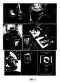
該デバイスの一例の模式図を図1に示す。該デバイスは、標的対象部10すなわち標的表面をイメージングするようにポジショニングされた状態で示されている。図示した例では、該デバイスは、デジタル画像取得デバイス1、例えば、デジタルカメラ、ビデオレコーダー、カムコーダー、デジタルカメラ内蔵の携帯電話、デジタルカメラ付き「スマート」フォン、パーソナルデジタルアシスタント(PDA)、デジタルカメラ付きラップトップ/PC、またはウェブカメラを有する。デジタル画像取得デバイス1はレンズ2を有し、これは、標的対象部10に向けて一直線上に配置され得、対象部10すなわち表面から発せられる光信号を検出し得る。該デバイスは光学フィルターホルダー3を有し、これには1つ以上の光学フィルター4が収容され得る。各光学フィルター4は異なる不連続のスペクトル帯域幅を有するものであり得、バンドパスフィルターであり得る。このような光学フィルター4は、光の波長に基づいて特定の光信号が選択的に検出されるように、選択され、デジタルカメラのレンズから移動し得る。該デバイスは光源5を含むものであり得、該光源は、例えば、青色光(例えば、400〜450nm)または単一波長もしくは複数波長(例えば、紫外/可視光/近赤外/赤外範囲の波長)の任意の他の組合せによりイメージングされる光信号(例えば、蛍光)を誘起するために対象部10に照射するための励起光を発する。光源5は、LEDアレイ、レーザーダイオードおよび/またはさまざまな幾何構造に構成されたフィルター処理光を含むものであり得る。該デバイスは、熱を放散させて照射光源5を冷却するためのメソッドまたは装置6(例えば、ヒートシンクまたは冷却ファン)を含むものであり得る。該デバイスは、イメージングする対象部10に照射するために使用される光源5から望ましくない波長の光を除外するためのメソッドまたは装置7(例えば、光学バンドパスフィルター)を含むものであり得る。該デバイスは、イメージングデバイスと対象部10間の距離を計測および測定するために光学的手段を使用するための方法または装置8(例えば、コリメート光ビームを放射するコンパクトな小型レーザーダイオードの使用)を含むものであり得る。例えば、該デバイスは、該デバイスと対象部10間の一定距離を維持するために、三角測量装置の一部として2つの光源、例えば2つのレーザーダイオードを使用するものであってもよい。他の光源も可能であり得る。また、該デバイスは、維持する一定距離を測定するために、ルーラーなどの超音波または物理的手段を使用するものであってもよい。別の例示的な実施形態によれば、該デバイスは、イメージングする創傷部に対して適切な該デバイスのポジションを決定するために距離計を使用するものであり得る。また、該デバイスは、種々の距離で対象部10に当たる光の照射角を変えるためにこれらの光源5,8が操作されるように、励起光源5,8の操作および方向決めを可能にするためのメソッドまたは装置9(例えば、ピボット)を含むものであり得る。 A schematic diagram of an example of the device is shown in FIG. The device is shown in a position positioned to image the
標的対象部10に、該対象部の複数画像を撮像し、次いで解析のために重ね合わせることを可能にするためにマーク11で印を付けてもよい。マーク11は、例えば、異なる色の外因性蛍光色素の使用を伴うものであり得(これにより、光源5によって照射された場合に複数の相違する光信号がもたらされ得、これらは対象部10の画像内で検出可能であり得る)、したがって、これらの異なる色および相互の距離を重ね合わせることにより同じ関心領域の複数画像(例えば、経時的に撮像)の方向決めが可能となり得る。デジタル画像取得デバイス1は:ヘッドマウントディスプレイのインターフェース12;外部プリンターのインターフェース13;タブレットコンピュータ、ラップトップコンピュータ、デスクトップコンピュータまたは他のコンピュータデバイスのインターフェース14;リモートサイトまたは別のデバイスへのイメージングデータの有線または無線転送を可能にするデバイスのインターフェース15;グローバルポジショニングシステム(GPS)デバイスのインターフェース16;増設メモリの使用を可能にするデバイスのインターフェース17;およびマイクロホンのインターフェース18のうちの1つ以上を含むものであり得る。 The
該デバイスは、電源19、例えば、AC/DC電源、コンパクトなバッテリーバンクまたは充電式バッテリーパックを含むものであり得る。あるいは、該デバイスは、外部電源との接続に適合させたものであってもよい。該デバイスは、すべての構成要素を1つの実体で収容するハウジング20を有するものであってもよい。ハウジング20は、任意のデジタルイメージングデバイスをその内部に固定する手段を備えたものであり得る。ハウジング20は、手持ち式、コンパクトおよび/または携帯型となるように設計され得る。ハウジング20は1つ以上の収容部であってもよい。 The device may include a
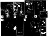
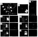
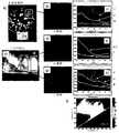
図2は、典型的な創傷ケア施設における該デバイスの一例を示す。インセットa)は、検査用イスおよび付属のテーブルを示す典型的な創傷ケアの臨床施設を示す。インセットb〜c)は、ハードケースコンテナにおける該デバイスの一例を示す。該デバイスは常套的な創傷ケア実務に統合され、患者のリアルタイムイメージングが可能であり得る。インセットd)は、該デバイスのサイズを示すために「創傷ケアカート」に置かれた該デバイス(矢印)の一例を示す。インセットe)該デバイスは白色光照射下でイメージングする使用され得るが、インセットf)は、うす暗い室内光で創傷部の蛍光画像の撮像のために使用されている該デバイスを示す。インセットg)該デバイスは、遠隔医療(telemedicine/telehealth)インフラにおいて使用され得る、例えば、患者の創傷部の蛍光画像は、電子メールにより創傷ケア専門医に無線通信デバイスによって、例えば、スマートフォンで別の病院に無線/WiFiインターネット接続を用いて送られ得る。このデバイスを使用すると、高解像度蛍光画像が電子メールの添付書類として、創傷ケア専門医に遠隔の創傷ケアの場所から、臨床的創傷ケアマネージメントの専門施設に居る臨床専門医、微生物学者などに、直接相談のために送られ得る。 FIG. 2 shows an example of the device in a typical wound care facility. Inset a) shows a typical wound care clinical facility showing a test chair and an attached table. Insets b to c) show an example of the device in a hard case container. The device may be integrated into conventional wound care practices and enable real-time imaging of patients. Inset d) shows an example of the device (arrow) placed in a "wound care cart" to indicate the size of the device. Inset e) The device can be used for imaging under white light irradiation, while inset f) indicates the device used for imaging a fluorescent image of the wound in dim room light. Inset g) The device can be used in a telemedicine / telehealth infrastructure, eg, a fluorescent image of a patient's wound is emailed to a wound care specialist by a wireless communication device, eg, on a smartphone. It can be sent to the hospital using a wireless / WiFi internet connection. With this device, high-resolution fluorescent images can be emailed as attachments to a wound care specialist directly from a remote wound care location to a clinical specialist, microbiologist, etc. in a clinical wound care management facility. Can be sent for.
実施例
蛍光ベースモニタリングのためのデバイスの一例を以下に説明する。すべての実施例は、実例を示す目的で示したものにすぎず、限定を意図するものではない。実施例に記載の波長、寸法およびインキュベーション時間などのパラメータは近似値であり得、一例として示したものにすぎない。Examples An example of a device for fluorescence-based monitoring will be described below. All examples are provided for the purpose of demonstrating examples and are not intended to be limiting. Parameters such as wavelength, dimensions and incubation time described in the examples can be approximate values and are shown as examples only.
この実施例において、デバイスは、各々がイメージング検出器アセンブリのそれぞれの側面に励起光源または照射光源として配置される2つの紫(violet)/青色光(例えば、405nm+/−10nm発光,狭い発光スペクトル)LEDアレイ(Opto Diode Corporation,Newbury Park,California)を使用したものである。これらのアレイは、各々、およそ1ワットの出力を有し、2.5×2.5cm2から70度の照射ビーム角で放射する。これらのLEDアレイは、約10cmの距離から(これは、皮膚表面における総光学出力密度が約0.08W/cm2であることを意味する)組織表面に照射するために使用され得る。かかる低出力では、標的の創傷部もしくは皮膚表面または目のいずれに対しても励起光による潜在的影響は知られていない。しかしながら、イメージング手順中に、いずれかの個体の目に光が直接当たることはよろしくなかろう。また、国際電気標準会議(IEC)に定められた国際基準によれば、405nmの光は健康に対してリスクを有するものではないことに注意されたい(ウェブサイト:http://www.iec.ch/online_news/etech/arch_2006/etech_0906/focus.htmにさらに詳述されている)。In this embodiment, the device has two violet / blue light (eg, 405 nm +/- 10 nm emission, narrow emission spectrum), each placed as an excitation or irradiation light source on each side of the imaging detector assembly. An LED array (Opto Diode Corporation, Newbury Park, California) is used. Each of these arrays has an output of approximately 1 watt and emits at an irradiation beam angle of 2.5 x 2.5 cm2 to 70 degrees. These LED arrays can be used to illuminate the tissue surface from a distance of about 10 cm (which means that the total optical output density on the skin surface is about 0.08 W / cm2 ). At such low powers, the potential effect of excitation light on either the target wound or skin surface or the eye is unknown. However, it would be imperative that the eyes of any individual be exposed to direct light during the imaging procedure. Also note that according to the international standards set by the International Electrotechnical Commission (IEC), light at 405 nm does not pose a health risk (website: http://www.iec. (more detailed in ch / online_news / ech / arch_2006 / ech_0906 / focal.html).
該1つ以上の光源は、例えば内蔵型ピボットの使用によりイメージング対象表面上の照射角およびスポットサイズ変更されるため、明示される場合があり得(例えば、手動で)、例えば、壁コンセントおよび/または別個の携帯型充電式バッテリーパックとの電気的接続によって電力供給される。励起/照射光は、電源、例えば限定されないが、単一もしくは複数の発光ダイオード(LED)(任意の構成、例えば、円環もしくはアレイ形式)、波長フィルター処理光電球またはレーザーによって生成され得る。また、紫外(UV)、可視光(VIS)、遠赤外、近赤外(NIR)および赤外(IR)範囲の特定の波長特性を有する選択された単一および複数の励起/照射光源が使用され得、LEDアレイ、有機LED、レーザーダイオード、またはさまざまな幾何構造に構成されたフィルター処理光で構成されたものであり得る。励起/照射光源は、該デバイスから発せられる光強度イメージング中に調整可能であるように「チューニング」され得る。光強度は可変的であり得る。LEDアレイは、動作中に発生する熱を放散させるために個々の冷却ファンまたはヒートシンクに取り付けてもよい。LEDアレイは狭い405nmの光を放射するものであり得、この光は、検出光学系内への放射光の「漏れ」の可能性を低減させるために市販のバンドパスフィルター(Chroma Technology Corp,Rockingham,VT,USA)を用いてスペクトルフィルター処理されたものであり得る。該デバイスがイメージング対象の組織表面(例えば、創傷部)の上部に保持されているときに、照射光源から狭帯域幅または広帯域幅の紫/青色波長または他の波長もしくは波長帯域の光が組織/創傷部表面上に照射され得、それにより、関心領域内にフラットで均一な場がもたらされ得る。また、該光は、組織の一定の浅層部まで照射または励起するものであってもよい。この励起/照射光は、正常組織および罹病組織と相互作用し、該組織内で生成する光信号(例えば、吸収、蛍光および/または反射率)をもたらし得るものである。 The one or more light sources may be specified (eg, manually), eg, wall outlets and / or because the illumination angle and spot size on the surface to be imaged are altered, for example by the use of a built-in pivot. Alternatively, it is powered by an electrical connection with a separate portable rechargeable battery pack. The excitation / illumination light can be generated by a power source, such as, but not limited to, a single or multiple light emitting diodes (LEDs) (any configuration, eg, ring or array form), wavelength filtered light bulbs or lasers. Also, selected single and multiple excitation / irradiation sources with specific wavelength characteristics in the ultraviolet (UV), visible light (VIS), far infrared, near infrared (NIR) and infrared (IR) ranges. It can be used and can be composed of an LED array, an organic LED, a laser diode, or filtered light configured in various geometric structures. The excitation / irradiation light source can be "tuned" to be adjustable during light intensity imaging emanating from the device. The light intensity can be variable. The LED array may be attached to individual cooling fans or heat sinks to dissipate the heat generated during operation. The LED array can emit narrow 405 nm light, which is a commercially available bandpass filter (Chroma Technology Corp, Rockingham) to reduce the possibility of “leakage” of the emitted light into the detection optics. , VT, USA) and can be spectrally filtered. When the device is held on top of the tissue surface to be imaged (eg, a wound), light in a narrow or wide bandwidth purple / blue wavelength or other wavelength or wavelength band is emitted from the irradiation source. It can be applied onto the wound surface, which can provide a flat and uniform field within the area of interest. Further, the light may irradiate or excite a certain shallow layer portion of the tissue. This excitation / irradiation light can interact with normal and diseased tissues to provide light signals (eg, absorption, fluorescence and / or reflectance) generated within the tissues.
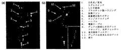
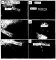
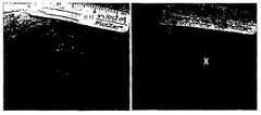
励起波長および発光波長を相応に変更することにより、イメージングデバイスによって、組織(例えば、創傷部)の表面および一定の深部の組織成分(例えば、創傷部内の結合組織および細菌)がインテロゲーションされ得る。例えば、紫/青色(約400〜500nm)波長を緑色(約500〜540nm)波長の光に変更することにより、例えば創傷部において深部組織/細菌の蛍光源の励起がなされ得る。同様に、長波長を検出することにより、組織深部の組織および/または細菌の光源からの蛍光発光が組織表面で検出され得る。創傷部評価では、表面および/または表面下層の蛍光のインテロゲーション能は、例えば、創傷部(例えば、非治癒性慢性創傷部)の表面および多くの場合、その深部に存在し得る細菌の汚染、コロニー形成、危機的コロニー形成および/または感染の検出およびその可能性の特定において有用であり得る。一例において、図3を参照すると、インセットc)は、創傷部清拭後の皮膚表面下(すなわち、深部)における細菌の検出を示す。創傷部および周辺組織の表面および深部の細菌を検出するための該デバイスのこの使用は、創傷ケア施設で慣用的に使用される他の臨床的徴候および症状の状況において評価され得る。 By appropriately varying the excitation and emission wavelengths, the imaging device can interrogate tissue (eg, wound) surface and certain deep tissue components (eg, connective tissue and bacteria within the wound). .. For example, by changing the violet / blue (about 400-500 nm) wavelength to light having a green (about 500-540 nm) wavelength, a deep tissue / bacterial fluorescence source can be excited, for example, in the wound. Similarly, by detecting long wavelengths, fluorescence from deep tissue and / or bacterial light sources can be detected on the tissue surface. In wound assessment, the fluorescent interrogation ability of the surface and / or subsurface layer is, for example, contamination of the surface of the wound (eg, non-healing chronic wound) and often deep in it. , Colonization, critical colonization and / or detection of infection and identification of its potential. In one example, referring to FIG. 3, inset c) shows the detection of bacteria under the skin surface (ie, deep) after wound cleaning. This use of the device for detecting surface and deep bacteria in wounds and surrounding tissues can be evaluated in the context of other clinical signs and symptoms commonly used in wound care facilities.
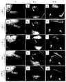
該デバイスの一例を図4に示す。該デバイスは、画像取得デバイスとして任意の標準的なコンパクトなデジタルイメージングデバイス(例えば、電荷結合素子(CCD)または相補型金属酸化膜半導体(CMOS)センサー)とともに使用され得る。a)に示したデバイス例は、外部電源、イメージングする対象部/表面に照射するための2つのLEDアレイ、およびイメージングのための簡便なハンドルを備えた軽量金属フレームにしっかり固定された市販のデジタルカメラを有する。イメージングする対象部/表面から発せられる検出対象の光信号の波長のフィルタリングを可能にするためのマルチバンドフィルターがデジタルカメラの前面に保持されている。カメラのビデオ/USB出力ケーブルにより、保存およびその後の解析のためにコンピュータにイメージングデータを転送することが可能である。この例には市販の8.1メガピクセルのSony製デジタルカメラ(Sony Cybershot DSC−T200 Digital Camera,Sony Corporation,North America)が使用されている。このカメラは、i)該収容部フレーム内に統合されやすい、そのスリムな縦型のデザイン、ii)コントロールが容易な、その大きな3.5インチのタッチパネル式LCDワイド画面、iii)そのカールツァイス5倍光学ズームレンズ、およびiv)その微小光での使用(例えば、ISO3200)のため好適であり得る。該デバイスは、標準的な白色光イメージングを可能にする内蔵フラッシュを有するものであってもよい(例えば、音声記録出力部を有する高画質スチルまたはビデオ)。カメラインターフェースポートは、有線(例えば、USB)または無線(例えば、Bluetooth(登録商標),WiFiおよび同様のモダリティ)のどちらでも、さまざまな外部デバイス、例えば;ヘッドマウントディスプレイ、外部プリンター、タブレットコンピュータ、ラップトップコンピュータ、パーソナルデスクトップコンピュータ、リモートサイト/他のデバイスへのイメージングデータの転送を可能にする無線デバイス、グローバルポジショニングシステム(GPS)デバイス、増設メモリの使用を可能にするデバイスおよびマイクロホンへのデータ転送またはサードパーティアドオンモジュールをサポートするものであり得る。デジタルカメラは、充電式バッテリーまたはAC/DC電源によって電力供給される。デジタルイメージングデバイスとしては、限定されないが、デジタルカメラ、ウェブカメラ、デジタルSLRカメラ、カムコーダー/ビデオレコーダー、デジタルカメラ内蔵の携帯電話、スマートフォン(商標)、パーソナルデジタルアシスタント(PDA)、およびラップトップコンピュータ/タブレットPC、またはパーソナルデスクトップコンピュータが挙げられ得、これらはすべて、デジタルイメージング検出器/センサーを含むもの/または該検出器/センサーと接続されるものである。 An example of the device is shown in FIG. The device can be used as an image acquisition device with any standard compact digital imaging device (eg, a charge-binding element (CCD) or complementary metal oxide semiconductor (CMOS) sensor). The device example shown in a) is a commercially available digital camera firmly secured to a lightweight metal frame with an external power supply, two LED arrays for illuminating the subject / surface to be imaged, and a convenient handle for imaging. Have a camera. A multi-band filter is held in front of the digital camera to enable filtering of the wavelength of the light signal of the detection target emitted from the target part / surface to be imaged. The camera's video / USB output cable allows the imaging data to be transferred to the computer for storage and subsequent analysis. For this example, a commercially available 8.1 megapixel Sony digital camera (Sony Cyber-shot DSC-T200 Digital Camera, Sony Corporation, North America) is used. The camera is i) its slim vertical design, easy to integrate into the housing frame, ii) its large 3.5-inch touch panel LCD wide screen, iii) its Carl Zeiss 5 A magnification optical zoom lens, and iv) may be suitable for its use in micro light (eg, ISO3200). The device may have a built-in flash that enables standard white light imaging (eg, high quality stills or video with an audio recording output). The camera interface port can be either wired (eg, USB) or wireless (eg, Bluetooth®, WiFi and similar modalities) for a variety of external devices, such as; head-mounted displays, external printers, tablet computers, wraps. Data transfer or data transfer to top computers, personal desktop computers, wireless devices that allow the transfer of imaging data to remote sites / other devices, global positioning system (GPS) devices, devices that allow the use of additional memory and microphones It can support third-party add-on modules. Digital cameras are powered by rechargeable batteries or AC / DC power. Digital imaging devices include, but are not limited to, digital cameras, webcams, digital SLR cameras, camcorders / camcorders, mobile phones with built-in digital cameras, smartphones (trademarks), personal digital assistants (PDAs), and laptop computers / tablets. PCs, or personal desktop computers, may be mentioned, all of which include / or are connected to a digital imaging detector / sensor.
励起/照射光源によってもたらされるこの光信号はイメージングデバイスにより、励起光は拒絶するが検出対象の組織からの選択された波長の放射光は許容し、したがってディスプレイ上に画像が形成される光学フィルター(1つまたは複数)(例えば、Chroma Technology Corp,Rockingham,VT,USAから入手可能なもの)を用いて検出され得る。光学フィルターホルダーがデジタルカメラのレンズの前面の収容部フレームに取り付けられ、これには、異なる不連続のスペクトル帯域幅を有する1つ以上の光学フィルターが収容され得る(図4のインセットb)およびc)に示したとおり)。インセットb)は、LEDアレイのスイッチがオンで明るい紫/青色光を放射しており、単一の吸収フィルターを所定の位置に有する該デバイスを示す。インセットc)は、所望の波長特異的イメージングに適切なフィルターを選択するために使用されるマルチプル光学フィルターホルダーが使用された該デバイスを示す。インセットd)は、足の皮膚表面のイメージングをしながら片手で保持された該デバイスを示す。 This optical signal produced by the excitation / irradiation light source is an optical filter that rejects the excitation light but allows synchrotron radiation of a selected wavelength from the tissue to be detected, thus forming an image on the display. It can be detected using one or more) (eg, available from Chroma Technology Corp, Rockingham, VT, USA). An optical filter holder is attached to the housing frame on the front of the lens of the digital camera, which may contain one or more optical filters with different discontinuous spectral bandwidths (inset b in FIG. 4) and As shown in c)). Inset b) indicates the device in which the LED array is switched on to emit bright purple / blue light and has a single absorption filter in place. Inset c) indicates the device in which the multiple optical filter holder used to select the appropriate filter for the desired wavelength specific imaging was used. Inset d) shows the device held in one hand while imaging the skin surface of the foot.
このようなバンドパスフィルターは、所望の光の波長に基づいて組織/創傷部表面からの特定の光信号が選択的に検出されるように選択され、デジタルカメラのレンズの前面に一直線上に配置され得る。また、検出された光信号(例えば、吸収、蛍光、反射率)のスペクトルフィルタリングが、例えば、固体電子式チューナブルスペクトルバンドパスフィルターである、液晶チューナブルフィルター(LCTF)、または音響光学チューナブルフィルター(AOTF)を用いて行なわれ得る。また、スペクトルフィルタリングは、連続可変フィルターおよび/または手動式バンドパス光学フィルターの使用を伴うものであってもよい。このようなデバイスは、組織のマルチスペクトル、ハイパースペクトルおよび/または波長選択的イメージングがもたらされるようにイメージング検出器の前面に配置され得る。 Such bandpass filters are selected to selectively detect a particular optical signal from the tissue / wound surface based on the desired wavelength of light and are placed in a straight line in front of the lens of the digital camera. Can be done. Further, the spectral filtering of the detected optical signal (for example, absorption, fluorescence, reflectance) is, for example, a liquid crystal tunable filter (LCTF), which is a solid-state electronic tunable spectral bandpass filter, or an acoustic optical tunable filter. It can be done using (AOTF). Spectral filtering may also involve the use of continuously variable filters and / or manual bandpass optical filters. Such devices may be placed in front of the imaging detector to provide multispectral, hyperspectral and / or wavelength selective imaging of the tissue.
該デバイスを、妥当な様式で励起/照射光源およびイメージング検出器デバイスに取り付けられた光学的または方向可変偏光フィルター(例えば、線形または円環状と光学波長板の使用とを組み合わせる)を使用することにより改良してもよい。このようにして、該デバイスは、組織表面を、偏光照射と非偏光検出もしくはその逆、または偏光照射と偏光検出により、白色光反射率および/または蛍光イメージングのいずれかでイメージングするために使用され得る。これにより、最小限の正反射(例えば、白色光イメージングによるグレア)で創傷部のイメージングが可能になり得るとともに、創傷部および周囲の正常組織内の結合組織(例えば、コラーゲンおよびエラスチン)の蛍光偏光および/または異方性依存性変化のイメージングが可能になり得る。これにより、治癒中の創傷部リモデリングと関連している結合組織線維の空間的方向および構成に関する有用な情報が得られ得る。 By using the device in a reasonable manner with an excitation / irradiation light source and an optically or directional variable polarizing filter (eg, a combination of linear or annular and the use of an optical wave plate) attached to the imaging detector device. It may be improved. In this way, the device is used to image tissue surfaces with either white light reflectance and / or fluorescence imaging by polarized light and unpolarized light detection or vice versa, or polarized light and polarized light detection. obtain. This may allow imaging of the wound with minimal specular reflection (eg, glare by white light imaging) and fluorescent polarization of connective tissue (eg, collagen and elastin) within the wound and surrounding normal tissue. Imaging of and / or anisotropy-dependent changes may be possible. This can provide useful information about the spatial orientation and composition of connective tissue fibers associated with wound remodeling during healing.
イメージングデバイスのすべての構成要素を単一の構造体、例えば、片手または両手で楽に保持することを可能にするハンドルを有する人間工学的に設計された封入型構造体に統合してもよい。また、該デバイスを、ハンドルなしで提供してもよい。該デバイスは、軽量の携帯型であり得、白色光、蛍光および/または反射率イメージングモードを用いて任意の標的表面(例えば、皮膚および/または口腔、これもアクセス可能である)のリアルタイムデジタルイメージング(例えば、スチルおよび/またはビデオ)が可能なものであり得る。該デバイスは、イメージングのために体表面に沿って、該表面から可変的な距離で保持することによりスキャンされ得、明るい環境/室内で白色光反射率/蛍光をイメージングするために使用され得る。組織蛍光信号を最適化し、室内光によるバックグラウンド信号を最小限にするために該デバイスを薄暗い、または暗い環境/室内で使用してもよい。該デバイスは、創傷部および周囲の正常組織の直接(例えば、肉眼での)可視化に使用してもよく、間接(例えば、デジタルイメージングデバイスのビュー画面での)可視化に使用してもよい。 All components of the imaging device may be integrated into a single structure, eg, an ergonomically designed enclosed structure with handles that allow it to be comfortably held with one or both hands. The device may also be provided without a handle. The device can be lightweight and portable, real-time digital imaging of any target surface (eg, skin and / or oral cavity, which is also accessible) using white light, fluorescence and / or reflectance imaging modes. (For example, still and / or video) can be possible. The device can be scanned by holding it along the body surface for imaging at a variable distance from the surface and can be used to image white light reflectance / fluorescence in a bright environment / room. The device may be used in a dim or dim environment / room to optimize tissue fluorescence signals and minimize background signals from room light. The device may be used for direct (eg, macroscopic) visualization of the wound and surrounding normal tissue, or for indirect (eg, on the view screen of a digital imaging device) visualization.
また、該デバイスを手持ち式または携帯型でない実施形態にしてもよい、例えば、対象物、物質および表面(例えば、身体)の白色光、蛍光および反射率イメージングの比較的定置型の光学イメージングデバイスとしての使用のために、マウント機構(例えば、三脚またはスタンド)に取り付けられるようにしてもよい。これにより、該デバイスを、机もしくはテーブルの上で、または対象物、物質および表面の「流れ作業」イメージングに使用することが可能となり得る。一部の実施形態では、マウント機構はモバイル式であり得る。 The device may also be a non-handheld or portable embodiment, eg, as a relatively stationary optical imaging device for white light, fluorescence and reflectance imaging of objects, substances and surfaces (eg, the body). May be attached to a mounting mechanism (eg, a tripod or stand) for use. This may allow the device to be used on a desk or table, or for "assembly line" imaging of objects, substances and surfaces. In some embodiments, the mounting mechanism can be mobile.
このデバイスの他の特色としては、デジタル画像およびビデオ記録(場合によっては音声とともに)、文書化メソッド(例えば、画像の保存および解析ソフトウェアにより)、ならびに遠隔医療ニーズのための遠隔地への有線または無線データ伝送が挙げられ得る。例えば、図4のインセットe)およびf)は、画像取得デバイスが携帯電話などのモバイル通信デバイスである該デバイスの一実施形態を示す。この例で使用されている携帯電話はSamsung Model A−900であり、これは、1.3メガピクセルデジタルカメラを備えている。該電話は、簡便なイメージングのための保持フレーム内に取り付けられている。インセットe)は、「創傷部」という単語が蛍光インクで書かれた紙切れをイメージングするための該デバイスの使用を示す。インセットf)は、蛍光インクを塗った指のイメージングおよび一般的な皮膚細菌P.Acnesの検出を示す。携帯電話による画像は無線で別の携帯電話に、または無線で(例えば、Bluetooth接続によって)画像の保存および解析用のパーソナルコンピュータに送られ得る。これにより、該デバイスがリアルタイムの手持ち式蛍光イメージングおよび遠隔医療創傷ケアインフラの一部としてリモートサイト/遠隔地の人間への無線伝送を行なうことができる能力が実証される。 Other features of this device include digital image and video recording (possibly with audio), documentation methods (eg, by image storage and analysis software), and remote wired or remote for telemedicine needs. Radio data transmission can be mentioned. For example, insets e) and f) in FIG. 4 show an embodiment of the device in which the image acquisition device is a mobile communication device such as a mobile phone. The mobile phone used in this example is the Samsung Model A-900, which is equipped with a 1.3 megapixel digital camera. The phone is mounted within a holding frame for convenient imaging. Inset e) indicates the use of the device to image a piece of paper with the word "wound" written in fluorescent ink. Inset f) is a fluorescent-inked finger imaging and common skin bacteria P. The detection of Acnes is shown. Images from a mobile phone can be sent wirelessly to another mobile phone or wirelessly (eg, via a Bluetooth connection) to a personal computer for image storage and analysis. This demonstrates the ability of the device to perform real-time handheld fluorescence imaging and wireless transmission to remote humans as part of a telemedicine wound care infrastructure.
創傷ケアおよび他の該当する用途におけるイメージングデバイスの能力を実証するため、記載の具体例を用いていくつかの実現可能な実験を実施した。蛍光イメージングの全実験中、Sony製カメラ(Sony Cybershot DSC−T200 Digital Camera,Sony Corporation,North America)の設定は、画像がフラッシュなしで読み取られるように設定し、「マクロ」イメージングモード設定にしたことを認識されたい。画像は8メガピクセルで読み取った。白色光反射率画像の読み取りにはフラッシュを使用した。画像はすべて、長期保存および画像解析用のパーソナルコンピュータに後で転送するためにxDメモリーカードに保存した。 Several feasible experiments were performed using the specific examples described to demonstrate the capabilities of the imaging device in wound care and other applicable applications. During all fluorescence imaging experiments, the Sony camera (Sony Cyber-shot DSC-T200 Digital Camera, Sony Corporation, North America) was set to read the image without a flash and set to the "macro" imaging mode setting. Please be recognized. The image was read at 8 megapixels. A flash was used to read the white light reflectance image. All images were stored on an xD memory card for later transfer to a personal computer for long-term storage and image analysis.
例示的な一実施形態では、該デバイスで読み取られた白色光反射率画像および蛍光画像/ムービーは、画像解析のためのAdobe Photoshopにインポートした。しかしながら、画像解析ソフトウェアは、さまざまな画像ベーススペクトルアルゴリズム(例えば、赤対緑色蛍光比など)を用いて定量的検出/診断価値のための適切な画像データ(例えば、空間的スペクトルデータ)が抽出されること可能にするためにMatLab(商標)(Mathworks)を用いて設計されたものであった。また、画像の後加工には、画像の数学的編集を含めた。 In one exemplary embodiment, the white light reflectance images and fluorescence images / movies read by the device were imported into Adobe Photoshop for image analysis. However, image analysis software uses a variety of image-based spectral algorithms (eg, red to green fluorescence ratio) to extract appropriate image data (eg, spatial spectral data) for quantitative detection / diagnostic value. It was designed using MatLab ™ (Mathworks) to make it possible. In addition, post-processing of images included mathematical editing of images.
別の例示的な実施形態によれば、創傷部のデータの収集のための手持ち式デバイスは、プラスチック製の本体に収容された35〜140mm相当の4倍ズームレンズを有し、充電式バッテリーによって電力供給される低コストで消費者向け製品級のSuper HAD(商標)電荷結合素子(CCD)センサーベースのカメラ(Model DSC−T900,ソニー株式会社,日本)を含むものである(図5)。プロトタイプの手持ち式イメージングデバイスを図5に示す。インセット(a)は、リアルタイムで液晶ディスプレイ画面上に高画質で表示される創傷部の蛍光(FL)画像を示すこのプロトタイプの前面図である。インセット(b)は、創傷部の照射をもたらす白色光(WL)および405−nm LEDアレイを示すこのプロトタイプの背面図であるが、FL吸収フィルターはCCDセンサーの前面に配置されている。該デバイスは、高解像度12.1MピクセルカラーWLおよびAF画像(またはビデオ)がリアルタイム(<1秒)で収集されるように構成されており、画像は赤−緑−青色(RGB)形式で、該デバイスの3.5インチタッチセンスカラー液晶ディスプレイ(LCD)画面上に表示される(図5)。該デバイスは、広帯域幅の白色発光ダイオード(LED)を含み、標準的なAC125V電源によって電力供給され、WLイメージング中に照射をもたらすように構成されたものである。該デバイスは、さらに、FLイメージング中に4−W励起光出力をもたらすための2つの単色の紫−青(λexc=405_20nm)LEDアレイ(Model LZ4,LedEngin,San Jose,California)を含むものである(皮膚表面から10cmの距離で明るい均一な照射面積は約700cm2)。WLおよびFL画像は、デュアルバンドFLフィルター(λemiss=500〜550および590〜690nm)(Chroma Technologies Corp.,Vermont)に、皮膚表面で反射される励起光をブロックするためにカメラのレンズの前面に設置された高感度CCDセンサーによって検出される。該デバイスは、組織と細菌のAFがスペクトルによって分けられるように構成された吸収フィルターを含むものである。該デバイスは、スペクトルによって分けられた組織と細菌のAFが画像加工または色補正なしで合成RGB画像として表示され、したがって、ユーザーが創傷部および身体部位のこの解剖学的状況において細菌分布を確認することが可能であるように構成されている。CCD画像センサーは、外因性造影剤なしで、紫外(<400nm)、可視光(400〜700nm)および近赤外(700〜900nm)波長において組織および細菌のAFに対して感受性のものである。 According to another exemplary embodiment, the handheld device for collecting wound data has a 35-140 mm equivalent 4x zoom lens housed in a plastic body and is powered by a rechargeable battery. It includes a low-cost, consumer-grade Super HAD ™ charge-coupled device (CCD) sensor-based camera (Model DSC-T900, Sony Corporation, Japan) that is powered (Fig. 5). A prototype handheld imaging device is shown in FIG. Inset (a) is a front view of the prototype showing a fluorescence (FL) image of a wound that is displayed in high quality on a liquid crystal display screen in real time. Inset (b) is a rear view of this prototype showing white light (WL) and a 405-nm LED array that results in irradiation of the wound, but the FL absorption filter is located in front of the CCD sensor. The device is configured to collect high resolution 12.1M pixel color WL and AF images (or video) in real time (<1 second), in red-green-blue (RGB) format. It is displayed on the 3.5 inch touch sense color liquid crystal display (LCD) screen of the device (FIG. 5). The device includes a wide bandwidth white light emitting diode (LED) and is powered by a standard AC125V power supply and is configured to provide irradiation during WL imaging. The device further comprises two monochromatic purple-blue (λexc = 405_20 nm) LED arrays (Model LZ4, RedEngin, San Jose, California) to provide 4-W excitation light output during FL imaging (skin). A bright uniform irradiation area at a distance of 10 cm from the surface is about 700 cm2). WL and FL images were placed on the front of the camera lens to block excitation light reflected off the skin surface by dual band FL filters (λemiss = 500-550 and 590-690 nm) (Chroma Technologies Corp., Vermont). Detected by an installed high-sensitivity CCD sensor. The device includes an absorption filter configured such that tissue and bacterial AF are separated by spectrum. The device displays spectrally separated tissue and bacterial AF as a synthetic RGB image without image manipulation or color correction, thus allowing the user to confirm bacterial distribution in this anatomical situation of the wound and body part. It is configured to be possible. CCD image sensors are sensitive to tissue and bacterial AF at ultraviolet (<400 nm), visible light (400-700 nm) and near infrared (700-900 nm) wavelengths, without exogenous contrast media.
別の例示的な実施形態では、手持ち式デバイスは、白色光画像と蛍光画像の両方が撮像され、モバイル通信デバイス、例えば、スマートフォン、携帯電話、iPod(登録商標)、iPhone、またはCCDセンサーなどの既存の画像読み取り能を有する他のかかるデバイスが組み込まれるように構成されている。本明細書ではiPodタッチまたはiPhoneでの使用に関して記載しているが、他のプラットフォーム(例えば、Androidなど)も使用され得ることは理解されよう。例えば、図6Aに示すように、該デバイスにはiPhone 4Sが組み込まれる。モバイル式イメージングデバイスのプロトタイプを図6Aに示す。インセット(a)は、光学部品および付属アダプターのバッテリーホルダーを示す該デバイスの前面図を示し、これは、標準的なiPhone 4Sスマートフォンに設置されている。インセット(b)は、オン/オフスイッチおよびLCSビュー画面を示す該デバイスの背面図を示し、ビュー画面上のWLおよびFL画像をユーザーが見る。白光イメージングにより、ユーザーは患者の創傷部の画像を読み取ることが可能であり、蛍光により、ユーザーは、画像上の細菌の存在が強調された対応画像を読み取ることが可能である。ディスプレイ画面は約4インチ(対角線)〜約7インチ(対角線)のワイド画面ディスプレイの範囲で、マルチタッチIPS技術を有するものであり得る。ユーザーのニーズに基づいて他のサイズのディスプレイを使用してもよい。一例では、ディスプレイの画質設定は、326ピクセル/インチの1136×640ピクセル解像度;800:1のコントラスト比;および500cd/m2の最大輝度である。ディスプレイは、耐指紋性撥油コーティングを有するものであってもよい。カメラの解像度は約5メガピクセルであり得、利用可能性、利用可能な保存量などに応じて5メガピクセルより高い、例えば、約24メガピクセルまでもの解像度を有するものであってもよい。レンズ設計の選択により、特に赤色および緑色のスペクトルにおいて高品質の画像を得ることが可能である。例示的な一実施形態では、5−エレメントレンズが使用される(iPodタッチ設計)。ユーザーがビデオおよび/またはスチル画像をタップするとフォーカスされ得る。カメラは、暗所でも最適な性能を有するものである。カメラはLEDフラッシュを有し、シャッタースピードは高速である。 In another exemplary embodiment, the handheld device captures both white light and fluorescent images, such as mobile communication devices such as smartphones, mobile phones, iPods, iPhones, or CCD sensors. It is configured to incorporate other such devices with existing image readability. Although described herein for use with the iPod Touch or iPhone, it will be appreciated that other platforms (eg, Android, etc.) may also be used. For example, as shown in FIG. 6A, the device incorporates an iPhone 4S. A prototype of a mobile imaging device is shown in FIG. 6A. The inset (a) shows a front view of the device showing the optics and the battery holder of the accessory adapter, which is installed in a standard iPhone 4S smartphone. The inset (b) shows a rear view of the device showing an on / off switch and an LCS view screen, and the user views the WL and FL images on the view screen. White light imaging allows the user to read an image of the patient's wound, and fluorescence allows the user to read a corresponding image that emphasizes the presence of bacteria on the image. The display screen may range from about 4 inches (diagonal) to about 7 inches (diagonal) wide screen display and may have multi-touch IPS technology. Other sizes of displays may be used based on the needs of the user. In one example, the image quality settings of the display are 1136 x 640 pixel resolution of 326 pixels / inch; contrast ratio of 800: 1; and maximum brightness of 500 cd / m2. The display may have a fingerprint resistant oil repellent coating. The resolution of the camera can be about 5 megapixels and may be higher than 5 megapixels, for example up to about 24 megapixels, depending on availability, available storage and the like. Depending on the choice of lens design, it is possible to obtain high quality images, especially in the red and green spectra. In one exemplary embodiment, a 5-element lens is used (iPod touch design). Can be focused when the user taps the video and / or still image. The camera has optimum performance even in the dark. The camera has an LED flash and the shutter speed is high.
図6Aおよび6Bに示すように、この例示的な実施形態の手持ち式デバイスには、消費者向け製品級の携帯電話のカメラがカスタム光学プラットフォームによって統合されている。画像取得は携帯電話のカメラで行なわれ、デバイスハウジング、電子装置および光学素子とは独立して機能する。画像は、該電話のLCDタッチ画面上に表示され、該電話自体に保存される。このカスタマイズされた光学設計は、ダイクロイックミラー(これはカメラセンサーの前面に固定されている)に対して45度の角度でポジショニングされた1つの405nm紫LEDを含むものである。ダイクロイックミラーは、紫の光を反射するがそれより長いすべての波長は透過し、カメラセンサーと同軸の蛍光励起照射をもたらす。マクロレンズは、創傷部(<10cm)の集光クローズアップイメージングが可能となるようにカメラセンサーの前面に設置される。特定の組合せの励起フィルターと吸収フィルターが、赤色および緑色の蛍光データ(これらは、それぞれ、細菌および結合組織を示す)の読み取りに使用される。紫LEDは、ユーザーが外部電源スイッチからトリガーする標準的な9Vバッテリーによって電力供給される。ヒートシンクがLEDプリント回路基板の裏側に、5W紫LEDによって生成する熱を効果的に伝達および放散させるためのサーマルペーストにより取り付けられる。 As shown in FIGS. 6A and 6B, the handheld device of this exemplary embodiment integrates a consumer product grade mobile phone camera with a custom optical platform. Image acquisition is performed by the camera of the mobile phone and functions independently of the device housing, electronic devices and optics. The image is displayed on the LCD touch screen of the phone and stored on the phone itself. This customized optical design includes one 405nm purple LED positioned at a 45 degree angle to a dichroic mirror, which is fixed to the front of the camera sensor. Dichroic mirrors reflect purple light but transmit all longer wavelengths, resulting in fluorescence excitation irradiation coaxial with the camera sensor. The macrolens is placed in front of the camera sensor to allow focused close-up imaging of the wound (<10 cm). Certain combinations of excitation and absorption filters are used to read red and green fluorescence data, which indicate bacterial and connective tissue, respectively. The purple LED is powered by a standard 9V battery that the user triggers from an external power switch. A heat sink is attached to the back side of the LED printed circuit board with a thermal paste to effectively transfer and dissipate the heat generated by the 5W purple LED.
この例示的な実施形態によれば、該デバイスハウジングは3Dプリンティングによって作製されたものであり得る。他の型の好適な構造も本明細書に開示しており、その変形例は本教示に基づいて当業者に理解されよう。ハウジングは、光学部品を消費者向け製品級のカメラと一直線上に配置し、LEDを駆動させるために使用される電気部品とサーマルペーストの両方を収容する手段を提供するとともに、ユーザーが使用しやすく、軽量の手持ち式設計を創出するものである。アダプターは、iPhone 4sの上部を摺動し、イメージング中は所定の位置に固定されたままであるように該電話の周囲にぴったりと嵌合されるように設計される。アダプターは、白色光イメージングのための該電話から着脱可能である。別の例示的な実施形態によれば、アダプターは、iPhone 4sなどのモバイル通信デバイスに永続的に固定され得る。かかる実施形態では、図1および2で論考した手持ち式デバイスの実施形態に関して記載したものと同様の様式での白色光イメージングと蛍光イメージングの切換えのために可動式フィルターが設けられ得る。 According to this exemplary embodiment, the device housing can be made by 3D printing. Suitable structures of other types are also disclosed herein and variations thereof will be understood by those skilled in the art based on this teaching. The housing aligns the optics with a consumer-grade camera, providing a means of accommodating both the electrical components and thermal paste used to drive the LEDs, and is user-friendly. , Creates a lightweight handheld design. The adapter is designed to slide over the top of the iPhone 4s and fit snugly around the phone so that it remains fixed in place during imaging. The adapter is removable from the phone for white light imaging. According to another exemplary embodiment, the adapter may be permanently secured to a mobile communication device such as an iPhone 4s. In such an embodiment, a movable filter may be provided for switching between white light imaging and fluorescence imaging in a manner similar to that described for the handheld device embodiments discussed in FIGS. 1 and 2.
該デバイスを用いて蛍光イメージングを行なうためには、ユーザーは、該デバイスの裏側にあるトグルスイッチを用いて紫LEDのスイッチをオンにする(図6A)。スイッチが「オン」ポジションに移動すると、9Vバッテリーが、紫LEDを駆動するための電流を変調させるLEDドライブに電力を送る。この広帯域幅の紫LEDは、iPhoneカメラセンサーに対して垂直に位置しており、45度のダイクロイックミラーに対して405nmの光を放射する。ダイクロイックミラーは、405nm波長の光のほぼ100%を反射して標的に向かう。組織および細菌は紫LEDからの405nm光子を吸収し、長波長の光子は次いで、この細菌と組織によって放射され、蛍光が生じる。カメラセンサーに達し得る光子の波長を制御し、励起光を効果的にブロックするための特定の吸収フィルターをiPhoneカメラセンサーの前面に配置する。iPhoneカメラセンサーによって放射された光子のRGB画像が読み取られ、この画像では、細菌は赤色(例えば、黄色ブドウ球菌)または非常に明るい青っぽい緑色(例えば、緑膿菌)で表示され、皮膚または創傷部の健常な結合組織は緑色蛍光信号によって読み取られる。ユーザーは次いで、iPhoneなどのモバイル通信デバイスに保存された蛍光画像(またはビデオ)を用いて、創傷部内および創傷部周囲のどこに細菌が存在しているかを調べる。 To perform fluorescence imaging with the device, the user switches on the purple LED with a toggle switch on the back of the device (FIG. 6A). When the switch moves to the "on" position, the 9V battery powers the LED drive that modulates the current to drive the purple LED. This wideband purple LED is located perpendicular to the iPhone camera sensor and emits 405 nm light to a 45 degree dichroic mirror. The dichroic mirror reflects almost 100% of the light with a wavelength of 405 nm toward the target. Tissues and bacteria absorb 405 nm photons from the purple LED, and long-wavelength photons are then emitted by the bacteria and tissues, causing fluorescence. A specific absorption filter is placed in front of the iPhone camera sensor to control the wavelength of photons that can reach the camera sensor and effectively block the excitation light. An RGB image of the photons emitted by the iPhone camera sensor is read, in which the bacteria are displayed in red (eg Staphylococcus aureus) or very bright bluish green (eg Pseudomonas aeruginosa) and the skin or wound. Healthy connective tissue is read by a green fluorescent signal. The user then uses a fluorescent image (or video) stored on a mobile communication device such as the iPhone to find out where the bacteria are present in and around the wound.
例示的な一実施形態では、本明細書に記載の手持ち式デバイスを用いた試験により、患者の創傷部を経時的に追跡した。この試験では、各来院時に創傷部毎に高解像度WL PRODIGI画像を撮像した。WLおよびFLイメージング中、使い捨ての長さ換算表(ステッカー)を創傷部付近に置き、患者IDおよび日付を追跡した。医師が、プリントされたWL画像上の臨床的に有意な細菌量が疑われる位置に印を付けた。組織上における細菌の特性を保存するため、その後のFLイメージングが終了するまでスワブは採取しなかった。このプロセスは1つの創傷部につき1〜2分かかり、その後のFLイメージングは1つの創傷部につき1〜2分かかった。プリントされた画像上の陽性の赤色および/または緑色AFの位置(1つまたは複数)に印を付けた。医師は、印を付けた疑わしい領域の各々でLevineサンプリング法を用いてスワブ採取し、スワブを盲検的微生物学試験のために送った。患者は、標準的なプロトコルに従って処置し、退院させた。一部の症例では、FL分光法を用いて創傷部内/周囲のAF領域を特性評価した。スペクトルを、位置に基づいて微生物学試験結果と比較した。各患者の来院の完全データファイル(CSS、WLおよびFL画像、分光学および微生物学)を、Good Clinical Practiceガイドラインに従って電子データベースに保存した。 In one exemplary embodiment, the patient's wound was followed over time by testing with the handheld device described herein. In this test, high resolution WL PRODIGI images were taken for each wound at each visit. During WL and FL imaging, a disposable length conversion table (sticker) was placed near the wound and patient ID and date were followed. The doctor marked a position on the printed WL image where clinically significant bacterial levels were suspected. Swabs were not collected until subsequent FL imaging was completed to preserve the bacterial properties on the tissue. This process took 1-2 minutes per wound and subsequent FL imaging took 1-2 minutes per wound. The positive red and / or green AF positions (s) on the printed image were marked. Physicians took swabs in each of the marked suspicious areas using the Levine sampling method and sent the swabs for a blind microbiology study. Patients were treated according to standard protocols and discharged. In some cases, FL spectroscopy was used to characterize the AF region within / around the wound. The spectra were compared to microbiological test results based on position. Complete data files (CSS, WL and FL images, spectroscopy and microbiology) of each patient's visit were stored in an electronic database according to Good Clinical Practice guidelines.
試験の第2部では、3つの連続した2ヶ月処置群:非支援処置(対照)、FL支援処置および非支援処置(対照)を使用した。最初の2ヶ月相では、創傷部をCSSによって毎週評価し、次いで、臨床チームの自由裁量で最良の実務方法(超音波および/または外科用メスでの創傷部デブリードマン、局所/全身性抗生物質、生理食塩水での洗浄、乾燥包帯もしくは抗菌包帯、またはヨードチンキ)を用いて処置した。処置前および処置後の各創傷部の対応するWLおよびFL画像を、先に記載のようにして撮像した。2ヵ月の評価期間は、治癒の予測インジケータとして、創傷部領域の信頼性があり意味のある変化を検出するのに充分であることを示す静脈下腿潰瘍について確立された臨床的データに基づいて選択した。創傷部スワブはFL支援によって収集した。この第1(対照)相の間、医師にはFL画像を伏せた。続く2ヵ月相では、創傷部評価が標準的に行なわれたが、処置時に、医師に創傷部のFL画像が示された。 In
最後の2ヵ月相では、WLおよびFLイメージングが行なわれ、処置の施術時に医師にFL結果を伏せてスワブが収集された。重要なことに、医師は、赤色蛍光信号および緑色蛍光信号のそれぞれの意味および特性を理解し、思い出すことができたが、各創傷部検査および各患者の蛍光結果が異なるため、対照期間の処置の施術時に医師に伏せることは可能であった。したがって、創傷部処置時にリアルタイム蛍光支援がない場合、蛍光による特徴の予備知識は対照期間における処置判断に実質的に影響しなかった。また、WLおよびFL画像は、創傷部領域を解析するために各処置後にも撮像した。 In the last two months phase, WL and FL imaging was performed and swabs were collected with the FL results hidden from the physician during the procedure. Importantly, physicians were able to understand and remember the meaning and characteristics of the red and green fluorescent signals, respectively, but treatment during the control period due to the different fluorescence results of each wound examination and each patient. It was possible to lie down on the doctor during the procedure. Therefore, in the absence of real-time fluorescence support during wound treatment, prior knowledge of fluorescence characteristics did not substantially affect treatment decisions during the control period. WL and FL images were also taken after each procedure to analyze the wound area.
4名の訓練された臨床および/または研究スタッフメンバーが独立して、盲検的に、WL画像上の平均創傷部サイズをデジタル追跡(MATLAB v.7.9.0,The MathWorks,Massachusetts,USA)を用いて測定した。観測者らは、記憶効果を最小限にするために次の施術期間まで最低7日間あけて離れた施術期間で創傷部を測定した。イメージング中に創傷部に隣接して置いた接着性スケールバーにより、+0.5mm以内の正確な長さのキャリブレーションがもたらされた。WLイメージング中では室内光は依然としてあったが、FLイメージング中は消した。WLおよびFL画像を、創傷部から10〜15cmのところで保持/ポジショニングした手持ち式デバイスにより収集した。すべてのイメージングパラメータ(距離、露光時間、ISO設定、ホワイトバランスなど)は来院間で一定に維持した。創傷部(小さい直径の創傷部)から5cm未満の距離では、カメラの内蔵マクロモードを使用した。オートフォーカスにより迅速な(約1秒)画像取得が可能であった。画像(またはビデオ)をリアルタイムで読み取り、カメラのメモリーカードに保存した。WLモードとFLモード間の切換えは、内蔵「トグルスイッチ」を用いて実質的に瞬時であった。使用毎にデバイスを70%エチルアルコールで汚染除去した。 Four trained clinical and / or research staff members independently and blindly digitally track mean wound size on WL images (MATLAB v.7.9.0, The MathWorks, Massachusetts, USA). ) Was used for measurement. Observers measured the wounds at least 7 days apart until the next treatment period to minimize memory effects. An adhesive scale bar placed adjacent to the wound during imaging provided an accurate length calibration within +0.5 mm. Room light was still present during WL imaging but was extinguished during FL imaging. WL and FL images were collected with a handheld device held / positioned 10-15 cm from the wound. All imaging parameters (distance, exposure time, ISO settings, white balance, etc.) were kept constant between visits. At a distance of less than 5 cm from the wound (small diameter wound), the camera's built-in macro mode was used. It was possible to acquire images quickly (about 1 second) by autofocus. Images (or videos) were read in real time and saved to the camera's memory card. Switching between WL mode and FL mode was virtually instantaneous using the built-in "toggle switch". The device was decontaminated with 70% ethyl alcohol after each use.
WLおよびAF画像をラップトップに転送した。クリニック来院毎に、各創傷部の個々の1024×1024ピクセルFL画像から関心領域(ROI)を特定した。RGB画像を個々のチャネルに分離した。RGB画像の緑色チャネルおよび赤色チャネルは、インビボで検出された組織および細菌の真のAF信号の代表的なものであった。個々のFL画像から細菌レベルを定量するため、以下の画像処理手順を使用した。簡単には、各RGB画像の個々の緑色画像チャネルおよび赤色画像チャネルをグレースケールに変換し(青色チャネルは使用しなかった)、グレースケール強度が所与のヒストグラム閾値(未加工画像のバックグラウンドノイズが低減されるように選択)より上であるピクセルを計数した。赤色FL細菌のための赤色カラーマスクを、グレースケールで100〜255の色の範囲における極大を見出すことにより作出した。次いで、反転緑色カラーマスクを用いて緑色FLを除外した。赤色FL(ヒストグラム閾値より上)を有するすべてのピクセルを2値化し、すべての「1」ピクセルの合計を計算した。これを、各画像の緑色チャネルについても繰り返した。このデータにより、各画像における赤色(または緑色)細菌の量の推定量を得た。FLピクセル数を、接着性長さキャリブレーションステッカーを用いて、より有用なピクセル面積測定値(cmz)に変換し、それにより蛍光細菌の総量を面積測定値として得た。 The WL and AF images were transferred to the laptop. For each clinic visit, a region of interest (ROI) was identified from individual 1024 x 1024 pixel FL images of each wound. The RGB images were separated into individual channels. The green and red channels of the RGB images were representative of the true AF signals of tissues and bacteria detected in vivo. The following image processing procedure was used to quantify bacterial levels from individual FL images. Simply convert the individual green and red image channels of each RGB image to grayscale (blue channels were not used) and the grayscale intensity gives a given histogram threshold (background noise in the raw image). The pixels above (selected to be reduced) were counted. A red color mask for red FL bacteria was created by finding a maximum in the color range of 100-255 on a grayscale. The green FL was then excluded using an inverted green color mask. All pixels with red FL (above the histogram threshold) were binarized and the sum of all "1" pixels was calculated. This was repeated for the green channel of each image. This data provided an estimate of the amount of red (or green) bacteria in each image. The number of FL pixels was converted to a more useful pixel area measurement (cmz) using an adhesive length calibration sticker, whereby the total amount of fluorescent bacteria was obtained as the area measurement.
皮膚の内因性コラーゲンまたはエラスチンによってもたらされた組織AFは緑色FLとして現れ、臨床的に適切な細菌コロニー(例えば、黄色ブドウ球菌)は赤色FLとして現れた(内因性ポルフィリンによって引き起こされる。一部の細菌(例えば、緑膿菌(Pseudomonus aeruginosa))は、シデロホア/ピオベルジンにより青緑色信号を発生し、これは、画像解析ソフトウェアを用いてスペクトルにより組織構造的に皮膚AFと識別された。WLおよびFL画像は、デュアルバンドFLフィルター(λemiss=500〜550および590〜690nm)(Chroma Technologies Corp,VT,USA)とともに設置した高感度CCDセンサーにより1秒未満で収集した。CCD画像センサーは約300〜800nmの広い波長範囲にわたって感受性であった。PRODIGIは、ルーチン的な臨床作業フローに容易に統合された。組織FLを細菌FLと単一の合成画像に合わせることにより、医師は、創傷部および身体部位の解剖学的状況における細菌量の分布および程度を瞬時に視認した。典型的には、FLイメージングは、創傷部の数およびFL支援スワブ採取時間にもよるが、創傷部評価ルーチンに対しておよそ1〜3分間/患者の追加であった。Tissue AF provided by the skin's endogenous collagen or elastin appears as green FL, and clinically relevant bacterial colonies (eg, Staphylococcus aureus) appear as red FL (caused by endogenous porphyrins, in part. Bacteria (eg, Staphylococcus aeruginosa (Pseudomonus aeruginosa)) generate a bluish-green signal by Siderohoa / Piobergin, which was tissue-structuredly identified as skin AF using image analysis software. FL images were collected in less than 1 second by a high sensitivity CCD sensor installed with dual band FL filters (λemiss = 500-550 and 590-690 nm) (Chroma Technologies Corp, VT, USA). CCD image sensor is about 300. Sensitive over a wide wavelength range of ~ 800 nm. PRODIGI was easily integrated into routine clinical workflows. By matching tissue FL to a single synthetic image with bacterial FL, doctors were able to see the wound and the wound. Instantly visualized the distribution and extent of bacterial abundance in the anatomical context of body parts. Typically, FL imaging is performed for wound assessment routines, depending on the number of wounds and FL-assisted swab collection time. Approximately 1-3 minutes / additional patient.
AFイメージングにより、慣用的な方法では見逃される創傷周縁部の85%において臨床的に有意な細菌量が検出された。したがって、スワブ採取のためのLevine法だけでは創面環境は不充分であり得、おそらく、処置が不適切に差し控えられることになり得る。しかしながら、全創傷部の創傷周縁部のスワブ採取を含める標準的なサンプリング実務の修正は非現実的であり、費用がかかることとなり得よう。AFイメージングにより、医師が、創傷部マージンのサンプリングが必要であるかどうか、およびどこの創傷部マージンのサンプリングが必要であるかを判断することが補助されることとなり得よう。また、この手持ち式イメージングデバイスにより、潜在的再感染部位であり、従来の方法では検査またはスワブ採取されない、創傷部付近の周囲箇所における臨床的に有意なバイオバーデンが特定される。 AF imaging detected a clinically significant amount of bacteria in 85% of the wound margin that was missed by conventional methods. Therefore, the Levine method for swab collection alone may not be sufficient for the wound environment and may result in improper withholding of treatment. However, modifications to standard sampling practices, including swab sampling of the wound margin of all wounds, could be impractical and costly. AF imaging could help physicians determine if wound margin sampling is required and where wound margin sampling is required. The handheld imaging device also identifies clinically significant bioburden around the wound, which is a potential reinfection site and is not tested or swab-picked by conventional methods.
創傷部の細菌負荷を特定および定量することは、感染および治癒の重要な決定因子である。細菌量の可視化および定量的追跡に関するデータにより、画像支援デブリードマンならびに抗生物質および化膿止めの局所適用のための新しいシンプルな方法の特定がもたらされ、これにより、創傷周縁部に対する不必要な外傷が最小限となり、細菌負荷の低減に対するデブリードマンの寄与が最大化される。どの創傷部も感染の可能性を有するが、最良の実務方法によって真の感染を危機的コロニー形成と識別することは、依然として課題であり自由裁量であり、過剰処置および処置不足をもたらし得る。 Identifying and quantifying the bacterial load on the wound is an important determinant of infection and healing. Data on bacterial abundance visualization and quantitative tracking provide identification of new and simple methods for topical application of image-assisted debridement and antibiotics and antiseptic, which are unnecessary for the wound margin. Trauma is minimized and debridement's contribution to reducing bacterial load is maximized. Although any wound has the potential for infection, distinguishing a true infection from critical colony formation by best practice is still a challenge and discretion, which can lead to overtreatment and undertreatment.
複数の可変量、例えば、宿主の応答、局所および全身性の因子、灌流、免疫抑制、糖尿病および投薬物が感染のリスクに影響を及ぼす。危機的コロニー形成創傷部は、感染の古典的徴候または明白に高レベルのバイオバーデンを常に示しているとは限らないため、診断することが困難であり得る。実際、危機的コロニー形成創傷部を感染創傷部と区別することの臨床的重要性は、依然として議論を呼んでいる。感染が起こる前の無症状の患者の患者において、AFイメージングを用いて高い細菌量が特定されることは、積極的な処置を迅速に行なうことによって感染を予防する一助となり得る。細菌感染が疑われる場合、確立された臨床方針と、重細菌負荷のAFによる特定およびグラム陰性の緑膿菌とグラム陽性の黄色ブドウ球菌の識別とによって抗生物質の選択が手引きされ得よう。 Multiple variable doses, such as host response, local and systemic factors, perfusion, immunosuppression, diabetes and medications, affect the risk of infection. Crisis colonization wounds can be difficult to diagnose because they do not always show classic signs of infection or clearly high levels of bioburden. In fact, the clinical importance of distinguishing critical colonization wounds from infected wounds remains controversial. Identifying high bacterial levels using AF imaging in asymptomatic patients before infection can help prevent infection by rapid aggressive treatment. If bacterial infection is suspected, established clinical policies and identification by AF of heavy bacterial load and identification of Gram-negative Pseudomonas aeruginosa and Gram-positive Staphylococcus aureus could guide the selection of antibiotics.
別の例示的な実施形態では、画像解析は手持ち式デバイスで行なわれ得るか、またはWLおよびFL画像が画像処理用のラップトップに転送され得る。画像解析および画像データ処理は、手持ち式デバイスのプロセッサを用いて行なわれ得、かかる解析の結果は手持ち式デバイスのディスプレイ上に表示され得る。 In another exemplary embodiment, the image analysis can be performed on a handheld device or the WL and FL images can be transferred to a laptop for image processing. Image analysis and image data processing can be performed using the processor of the handheld device, and the results of such analysis can be displayed on the display of the handheld device.
以下の2つのプログラムが画像処理(例えば、Super HAD(商標)電荷結合素子(CCD)センサーベースのカメラ(Model DSC−T900)を用いて例示的な本デバイスによって収集されたデータの解析)に使用され得、このようなプロセスの一部を図7Aおよび7Bに示す:MATLABソフトウェア(バージョン7.9.0,The MathWorks,Massachusetts)はカスタム書き込みプログラムおよびImageJ Software(バージョン1.45n)を使用。MATLABプログラムにおいて、関心領域(ROI)を各創傷部の個々の1024×1024ピクセルFL画像から特定する。RGB画像を個々のチャネルに分離する。CCDセンサーによって検出されたそれぞれ組織成分および細菌からの緑色(500〜550nm発光)および赤色AF(>590nm)は、Sony CCD画像センサーの赤色フィルターおよび緑色フィルターとスペクトルが自然に一直線上に配置される。したがって、手持ち式デバイスのLCD画面上に表示されるRGB画像の緑色チャネルおよび赤色チャネルは、インビボで検出された組織および細菌の真のAF信号の代表的なものである。個々のFL画像から細菌レベルを定量するためには以下の画像処理手順が使用され得る。簡単には、各RGB画像の個々の緑色画像チャネルおよび赤色画像チャネルをグレースケールに変換し(青色チャネルは使用しない)、グレースケール強度が所与のヒストグラム閾値(未加工画像のバックグラウンドノイズが低減されるように選択)より上であるピクセルを計数する。一部の特定の実施形態では、例えば、組織の血管系/灌流をイメージングする場合に組織/血液によって吸収された405nmの励起光の量をイメージングする場合、青色チャネルが使用され得ようことが考えられ得る。 The following two programs are used for image processing (eg, analysis of data collected by an exemplary device using a Super HAD ™ Charge Coupling Element (CCD) sensor-based camera (Model DSC-T900)). Some such processes are shown in Figures 7A and 7B: MATLAB software (version 7.9.0, The MathWorks, Massachusets) uses a custom write program and ImageJ Software (version 1.45n). In the MATLAB program, a region of interest (ROI) is identified from an individual 1024 x 1024 pixel FL image of each wound. Separate the RGB image into individual channels. The green (500-550 nm emission) and red AF (> 590 nm) from the tissue components and bacteria detected by the CCD sensor are naturally aligned with the red and green filters of the Sony CCD image sensor. .. Therefore, the green and red channels of the RGB image displayed on the LCD screen of the handheld device are representative of the true AF signals of tissues and bacteria detected in vivo. The following image processing procedures can be used to quantify bacterial levels from individual FL images. Simply convert the individual green and red image channels of each RGB image to grayscale (without using the blue channel) and grayscale intensity gives a given histogram threshold (reduces background noise in raw images). Count the pixels above). In some specific embodiments, it is conceivable that a blue channel could be used, for example, when imaging the vascular system / perfusion of tissue and when imaging the amount of excitation light at 405 nm absorbed by tissue / blood. Can be.
赤色FL細菌のための赤色カラーマスクは、グレースケールで100〜255の色の範囲における極大を見出すことにより作出される。次いで、反転緑色カラーマスクを用いて緑色FLを除外する。赤色FL(ヒストグラム閾値より上)を有するすべてのピクセルを2値化し、すべての「1」ピクセルの合計を計算する。これを各画像の緑色チャネルについて繰り返す。このデータにより、各画像における赤色細菌の量の推定量を得る。FLピクセル数を、ピクセル画像上にルーラーを適用することによって、より有用なピクセル面積測定値(cm2)に変換し、それにより蛍光細菌の総量を面積測定値として得る(cm2)。創傷部のサイズが追跡され得、WL画像上の丸で囲んだ創傷部領域のピクセル面積をcm2に変換することにより同様に測定され得る。FL画像の解像度は、FLの領域に基づいて細菌を位置特定するのに充分である。ImageJソフトウェアは、カメラの画像メニューおよび色サブメニューに存在する内蔵バッチ処理機能「Split Channels」を用いてFL画像を赤色チャネル、緑色チャネルおよび青色チャネルに分離するために使用され得る。得られた各チャネルは表示され、グレースケールで保存される。さらなる解析のため、対応する赤色、緑色および青色の各チャネル画像においてROIを特定してもよい。内蔵解析メニューの「Set Measurement」機能は、各色チャネル画像についての以下の測定パラメータ:ピクセル面積、最小および最大グレースケール強度値、ならびに平均グレー強度値を選択および測定するために使用され得る。平均赤色チャネル強度値は、各赤色チャネル画像における(細菌)FL強度/正方形ピクセルとして求められ得、次いで、データの解析および比較に使用され得る。 Red color masks for red FL bacteria are created by finding a maximum in the 100-255 color range on a grayscale. The green FL is then excluded using an inverted green color mask. All pixels with red FL (above the histogram threshold) are binarized and the sum of all "1" pixels is calculated. This is repeated for the green channel of each image. This data gives an estimator of the amount of red bacteria in each image. The number of FL pixels is converted to a more useful pixel area measurement (cm2) by applying a ruler on the pixel image, thereby obtaining the total amount of fluorescent bacteria as the area measurement (cm2). The size of the wound can be tracked and similarly measured by converting the pixel area of the circled wound area on the WL image to cm2. The resolution of the FL image is sufficient to locate the bacteria based on the area of FL. ImageJ software can be used to separate FL images into red, green and blue channels using the built-in batch processing function "Split Channels" present in the camera's image menu and color submenu. Each resulting channel is displayed and stored in grayscale. ROIs may be identified in the corresponding red, green and blue channel images for further analysis. The "Set Measurement" function of the built-in analysis menu can be used to select and measure the following measurement parameters for each color channel image: pixel area, minimum and maximum grayscale intensity values, and average gray intensity values. The average red channel intensity value can be determined as the (bacterial) FL intensity / square pixel in each red channel image and then used for data analysis and comparison.
例示的な一実施形態では、マウス皮膚創傷部モデルを使用し、創傷部の状態を細菌感染の経過を相関させた(n=5;8〜12週齢;NCRNU−F)。相関は、Super HAD(商標)電荷結合素子(CCD)センサーベースのカメラ(Model DSC−T900)が組み込まれた上記の例示的な手持ち式デバイスを用いて得られたデータに基づいて行なった。経時的に感染状態になっているときの創傷部のWLおよびFL画像を毎日撮像した。赤色FL強度がピークになったとき抗菌処置(1日3回の局所ムピロシンを合計1日)を創傷部位に適用した。この処置の抗微生物効果を、手持ち式デバイスを用いて経時的にモニタリングし、処置後の創傷部のWLおよびFL画像を毎日取得した。創傷部を合計10日間モニタリングし(図8参照)、その後、マウスを致死させた。FL画像からの細菌量およびWL画像からの創傷部サイズを、上記のMATLABプログラムを用いて定量し、経時的に比較して創傷治癒状態を調べた。 In one exemplary embodiment, a mouse skin wound model was used to correlate the wound condition with the course of bacterial infection (n = 5; 8-12 weeks of age; NCRNU-F). Correlation was based on data obtained using the above exemplary handheld device incorporating a Super HAD ™ charge-coupled device (CCD) sensor-based camera (Model DSC-T900). WL and FL images of the wound as it became infected over time were taken daily. When the red FL intensity peaked, antibacterial treatment (local mupirocin three times daily for a total of 1 day) was applied to the wound site. The antimicrobial effect of this procedure was monitored over time using a handheld device and daily WL and FL images of the wound after the procedure were obtained. The wound was monitored for a total of 10 days (see Figure 8), after which the mice were lethal. The amount of bacteria from the FL image and the wound size from the WL image were quantified using the above MATLAB program and compared over time to examine the wound healing state.
図8は、10日間にわたって追跡した1匹のマウスの代表的なWLおよびFL画像を示す。インセット(a)は、プロトタイプのデバイスで撮像され、脊柱の両側の等しいサイズの2つの創傷部を示す画像を示す。右の創傷部には黄色ブドウ球菌(PBS中)を接種し、左の創傷部にはPBSのみ(対照)を接種した。上列はWL画像を示し、中列はFL画像を示し、下列は、細菌領域および強度に対応するMATLAB定量画像を示す。FLイメージングデータにより、黄色ブドウ球菌を接種した創傷部では対照創傷部と比べて細菌FL強度の有意な増大が示された(ピークは6日目)。ムピロシン(7日目,赤色矢印)により、細菌FLは8日目にほぼゼロまで有意に低減され、処置の効果が示された。細菌は9日目と10日目に再度増加した。インセット(b)は、インセット(a)で得られたFL画像での細菌量の定量的変化を示すグラフを示す。 FIG. 8 shows representative WL and FL images of one mouse followed for 10 days. Inset (a) is imaged with a prototype device and shows images showing two equally sized wounds on either side of the spinal column. The right wound was inoculated with Staphylococcus aureus (in PBS) and the left wound was inoculated with PBS only (control). The upper row shows the WL image, the middle row shows the FL image, and the lower row shows the MATLAB quantitative image corresponding to the bacterial region and intensity. FL imaging data showed a significant increase in bacterial FL intensity in S. aureus-inoculated wounds compared to control wounds (peak on day 6). Mupirocin (
別の例示的な実施形態によれば、BLIが、細菌量の測定のための最も感受性で信頼性のあるスクリーニングツールの1つであるため、インビボで細菌の絶対量を測定するために使用され得る。BLIにより、ルシフェラーゼとルシフェリンの酵素反応によって放射された光が収集され、したがって励起光は必要でない。手持ち式デバイス(いずれの外因性FL造影剤の投入は無し)を用いたFLイメージングおよび接種した黄色ブドウ球菌のBLIイメージングを経時的に追跡し、FL強度とBLI強度を比較した(図9参照)(n=7)。細菌のBLI信号は、手持ち式デバイスの消費者向け製品級−CCDカメラによって検出されたFL信号に寄与しなかった。生物発光性のグラム陽性黄色ブドウ球菌−Xen8.1(親株の黄色ブドウ球菌8325−4(Caliper)由来)を、病原体を接種する前日に対数増殖期中期まで培養した。BLIカセットを有する細菌はルシフェラーゼ酵素とその基質(ルシフェリン)を産生し、それにより、代謝活性である場合、440〜490nmの生物発光信号を放射する(図9)。細菌(1010CFU)を0.5mLのPBS中に懸濁させ、雌の無胸腺ヌードマウス(n=7;8〜12週齢;NCRNU−Fホモ接合型)の創傷部に注射した。黄色ブドウ球菌の生物発光を検出するため、創傷部のBLI画像を、接種前、接種直後ならびに接種後1、2、3、4、5、6および7日目に、Xenogen IVIS Spectrum Imaging System 100(Caliper,Massachusetts)の暗室内部で10秒間の露光時間を用いて取得した。BLI画像は、Living Image In Vivo Imagingソフトウェア(Caliper,Massachusetts)を用いて読み取った。ROIを創傷部でデジタル的に囲み、イメージングした各時点のROI内における総発光強度計数を測定した。BLI信号から測定された細菌の絶対量を、手持ち式デバイスを用いて(上記のとおり)同じ創傷部を経時的に撮像したFL画像上の対応するFL信号との相関について試験した。 According to another exemplary embodiment, BLI is used to measure the absolute amount of bacteria in vivo because it is one of the most sensitive and reliable screening tools for measuring bacterial mass. obtain. BLI collects the light emitted by the enzymatic reaction of luciferase and luciferin and therefore does not require excitation light. FL imaging with a handheld device (no exogenous FL contrast agent was added) and BLI imaging of inoculated S. aureus were followed over time and the FL and BLI intensities were compared (see FIG. 9). (N = 7). The bacterial BLI signal did not contribute to the FL signal detected by the consumer-grade-CCD camera for handheld devices. Bioluminescent Gram-positive Staphylococcus aureus-Xen8.1 (derived from parent strain Staphylococcus aureus 8325-4 (Caliper)) was cultivated until mid-exponential growth the day before inoculation with the pathogen. Bacteria with BLI cassettes produce a luciferase enzyme and its substrate (luciferin), which, when metabolically active, emit a bioluminescent signal of 440-490 nm (FIG. 9). Bacteria (1010 CFU) were suspended in 0.5 mL PBS and injected into the wound of female athymic nude mice (n = 7; 8-12 weeks old; NCRNU-F homozygous). To detect the bioluminescence of Staphylococcus aureus, BLI images of the wound were taken before, immediately after, and on
図9は、病原性細菌の自己蛍光(AF)強度がインビボ細菌量と相関していることを示す前臨床的データを示す。インセット(a)は、生物発光性黄色ブドウ球菌−Xen8.1(30μLのPBS中1010CFU)の接種前および接種後のマウスの皮膚創傷部のモバイル式プロトタイプデバイスによる画像の時間的推移を示す。創傷を有するマウスの接種後7日目までの各時点の代表的なWL(上列)、AF(中列)および生物発光(下列)画像を示す。BLIイメージングによりインビボで細菌の絶対量が得られる。赤色矢印は、テガダーム絆創膏を交換し、表面からのいくらかの細菌の除去が引き起こされたときを示す。インセット(b)は、時間の関数として示した黄色ブドウ球菌−Xen8.1(n=7匹のヌードマウス)からの平均赤色FLを示し、黄色ブドウ球菌FL(RGB画像の赤色チャネルからImageJソフトウェアを用いて計算)の毎日の増加を示す。2日目と7日目、動物プロトコルのとおりにテガダーム絆創膏を交換した。平均細菌FLは接種後4日目にピークになった。インセット(c)は、対応する生物発光の時間的推移のデータ(ROIから計算)を示し、創傷部における総細菌量の同様の増加および4日目のピークを示す。データは、創傷部における総細菌AFとインビボ細菌量間の強い正の相関を示す(ピアソン相関係数r=0.6889)。標準誤差を示す。スケールバー:(a)WL 1.5cmおよびAF,BLI 1cm。FIG. 9 shows preclinical data showing that the autofluorescence (AF) intensity of pathogenic bacteria correlates with the amount of in vivo bacteria. Inset (a) shows the temporal transition of images of the skin wounds of mice before and after inoculation with bioluminescent Staphylococcus aureus-Xen8.1 (1010 CFU in 30 μL PBS) by a mobile prototype device. Shown. Representative WL (upper row), AF (middle row) and bioluminescent (lower row) images at each time point up to 7 days after inoculation of wounded mice are shown. BLI imaging gives the absolute amount of bacteria in vivo. The red arrow indicates when the Tegaderm bandage was replaced, causing the removal of some bacteria from the surface. Inset (b) shows the average red FL from Staphylococcus aureus-Xen8.1 (n = 7 nude mice) shown as a function of time, and the Staphylococcus aureus FL (ImageJ software from the red channel of the RGB image). (Calculated using) shows the daily increase. On
微生物学的試料のイメージング
本イメージングデバイスは、微生物学臨床検査室におけるイメージングおよび/またはモニタリングに有用であり得る。該デバイスは、細菌コロニーの定量的イメージングおよび一般的な微生物学アッセイにおけるコロニー増殖の定量のために使用され得る。細菌コロニーの蛍光イメージングは増殖速度論を調べるために使用され得る。細菌コロニーの自動計数をもたらすソフトウェアが使用され得る。Imaging Microbiology Samples This imaging device can be useful for imaging and / or monitoring in a microbiological clinical laboratory. The device can be used for quantitative imaging of bacterial colonies and quantification of colony growth in common microbiological assays. Fluorescence imaging of bacterial colonies can be used to investigate growth kinetics. Software that results in automatic counting of bacterial colonies may be used.
細菌学/培養ラボラトリーにおける本デバイスの有用性を実証するため、生菌培養物をヒツジの血液寒天プレート上で培養した。細菌種には、化膿連鎖球菌、霊菌、黄色ブドウ球菌、表皮ブドウ球菌、大腸菌および緑膿菌を含めた(American Type Culture Collection,ATCC)。これらを培養し、37℃の標準的なインキュベーション条件下で維持し、「対数増殖期」の間であるときに実験に使用した。プレート内にコロニーが検出されたら(接種の約24時間後)、該デバイスを用いて、個々の細菌種を含有している寒天プレートを暗室内でイメージングした。紫/青色(約405nm)励起光を使用し、該デバイスを用いて、各寒天プレートの緑色自己蛍光と赤色自己蛍光の併存(約490〜550nmおよび約610〜640nm発光)と、赤色自己蛍光のみ(約635+/−10nm,蛍光性内因性ポルフィリンのピーク発光波長)の両方をイメージングした。各細菌種の蛍光画像を、比較のため、およびコロニー増殖のモニタリングのために経時的に撮像した。 To demonstrate the usefulness of the device in bacteriology / culture laboratories, live bacterial cultures were cultured on sheep blood agar plates. Bacterial species included Streptococcus pyogenes, S. aureus, Staphylococcus aureus, Staphylococcus epidermidis, Escherichia coli and Pseudomonas aeruginosa (American Type Culture Collection, ATCC). These were cultured and maintained under standard incubation conditions at 37 ° C. and used in experiments during the "logarithmic growth phase". Once colonies were detected in the plate (approximately 24 hours after inoculation), the device was used to image an agar plate containing individual bacterial species in a dark room. Using purple / blue (about 405 nm) excitation light, using the device, coexistence of green autofluorescence and red autofluorescence (about 490-550 nm and about 610-640 nm emission) of each agar plate and only red autofluorescence. Both (approximately 635 +/- 10 nm, peak emission wavelength of fluorescent endogenous porphyrin) were imaged. Fluorescent images of each bacterial species were imaged over time for comparison and for monitoring colony growth.
次に、図10を参照されたい。インセットa)は、ヒツジの血液寒天プレート上で培養している生菌培養物をイメージングして細菌の自己蛍光を検出するために使用されている該デバイスを示す。インセットb)は、緑膿菌によって放射された自己蛍光の画像を示す。また、該デバイスは、細菌のコロニー増殖を経時的に蛍光を用いて、接種後24時間目の寒天プレート上の自己蛍光性黄色ブドウ球菌の増殖の蛍光イメージングであるインセットc)に示すように、検出、定量および/またはモニタリングするためにも使用され得る。下側の画像において、明確な単独細菌コロニーが存在していることに注目のこと。紫/青色(例えば、405nm)励起光を使用し、該デバイスを用いて、インセットd)に示した化膿連鎖球菌;インセットe)に示した霊菌;インセットf)に示した黄色ブドウ球菌;インセットg)に示した表皮ブドウ球菌;インセットh)に示した大腸菌;およびインセットi)に示した緑膿菌を含むいくつかの生菌種による緑色と赤色の併存(例えば、490〜550nm+610〜640nm)と、赤色のみ(例えば、635+/−10nm,蛍光性内因性ポルフィリンのピーク発光波長)の両方の自己蛍光発光を検出した。該デバイスによって得られた細菌コロニーの自己蛍光画像により、細菌コロニー形成および増殖速度論のシンプルで長期的な定量的測定のための有用な画像対比ならびに一例として抗生物質、光線力学療法(PDT)、低反応レベル光治療、高気圧酸素療法(HOT)、または最新の創傷ケア製品を用いた治療的介入に対する応答が場合によってはモニタリングされる手段がもたらされ得ることに注目のこと。 Next, see FIG. Inset a) shows the device used to image live bacterial cultures cultured on sheep blood agar plates to detect bacterial autofluorescence. Inset b) shows an image of autofluorescence emitted by Pseudomonas aeruginosa. The device also shows bacterial colony growth over time using fluorescence inset c), which is a fluorescence imaging of the growth of autofluorescent Staphylococcus aureus on an agar plate 24 hours after inoculation. , Can also be used for detection, quantification and / or monitoring. Note the presence of distinct single bacterial colonies in the lower image. Using a purple / blue (eg, 405 nm) excitation light, the device was used to show Streptococcus pyogenes shown in inset d); Staphylococcus aureus shown in inset e); Staphylococcus aureus shown in inset f). Coexistence of green and red by several viable species including Staphylococcus epidermidis; Staphylococcus epidermidis shown in Inset g); Escherichia coli shown in Inset h); and Pseudomonas aeruginosa shown in Inset i) Both self-fluorescent emission was detected (490-550 nm + 610-640 nm) and red only (eg, 635 +/- 10 nm, peak emission wavelength of fluorescent endogenous porphylococcus aureus). Self-fluorescent images of bacterial colonies obtained by the device are useful image contrasts for simple, long-term quantitative measurements of bacterial colony formation and growth rate theory and, as an example, antibiotics, photodynamic therapy (PDT),. Note that response to low response level phototherapy, hyperbaric oxygen therapy (HOT), or therapeutic interventions with the latest wound care products may provide a means of monitoring in some cases.
カメラ検出器の高空間解像度を、該デバイスによるノイズに対して有意な細菌自己蛍光信号のイメージングと組み合わせることにより、非常に小さい(例えば、<1mmの直径)コロニーの検出が可能になった。該デバイスにより、標準的な寒天プレート中で培養している個々の細菌コロニーをイメージングする携帯型で感度のよい手段がもたらされた。これにより、インセットc)にみられるような細菌のコロニー増殖速度論を定量およびモニタリングするための手段、ならびに場合によっては、一例として抗生物質または光線力学療法(PDT)を用いた治療的介入に対する応答を経時的に蛍光を用いてモニタリングするための手段がもたらされた。したがって、該デバイスは、微生物学ラボラトリーにおける有用なツールとしての機能を果たし得る。 Combining the high spatial resolution of the camera detector with the imaging of bacterial autofluorescence signals that are significant to noise by the device has made it possible to detect very small (eg, <1 mm diameter) colonies. The device provided a portable and sensitive means of imaging individual bacterial colonies cultivated on standard agar plates. This allows for means for quantifying and monitoring bacterial colony kinetics as seen in inset c) and, in some cases, therapeutic interventions using antibiotics or photodynamic therapy (PDT), for example. A means for monitoring the response over time with fluorescence has been provided. Therefore, the device can serve as a useful tool in the microbiology laboratory.
図11は、インセットa)標準的な細菌学ラボラトリー実務における本イメージングデバイスの使用の一例を示す。インセットb)ここでは、黄色ブドウ球菌の入ったペトリ皿の蛍光イメージングを、カスタムプロプライエタリ画像解析ソフトウェアと組み合わせることにより、細菌コロニーが迅速に計数されること可能になっており、ここで、培養皿の蛍光画像は、寒天上で37℃にて培養中の約182(+/−3)個のコロニー(明るい青っぽい緑色のスポット)を示す(約405nm励起,約500〜550nm発光(緑色),約>600nm発光(赤色))。 FIG. 11 shows an example of inset a) use of the imaging device in standard bacteriology laboratory practice. Inset b) Here, by combining fluorescence imaging of a Petri dish containing yellow staphylococcus with custom proprietary image analysis software, bacterial colonies can be counted quickly, where the culture dish is available. Fluorescent image shows about 182 (+/- 3) colonies (bright bluish green spots) in culture at 37 ° C. on agar (about 405 nm excitation, about 500-550 nm emission (green), about. > 600 nm emission (red)).
細菌種の検出がもたらされることに加えて、該デバイスは、例えば、創傷部および周辺組織において異なる細菌種(例えば、黄色ブドウ球菌または緑膿菌(Pseudomonas aeguginosa))の存在および/または位置を区別するためにも使用され得る。これは、異なる細菌種の異なる自己蛍光発光サイン(例えば、405nm前後の光などの紫/青色光によって励起したとき、490〜550nm発光波長帯域のものと、610〜640nm発光波長帯域のもの)に基づいたものであり得る。画像上で他の種間を識別するために他の波長の組合せを使用してもよい。この情報は、抗生物質の選択などの適切な処置を選択するために使用され得る。 In addition to providing detection of bacterial species, the device distinguishes, for example, the presence and / or location of different bacterial species (eg, Staphylococcus aureus or Pseudomonas aeguginosa) in the wound and surrounding tissue. Can also be used to. This applies to different autofluorescent signs of different bacterial species (eg, those in the 490-550 nm emission wavelength band and those in the 610-640 nm emission wavelength band when excited by purple / blue light such as light around 405 nm). It can be based. Other wavelength combinations may be used to distinguish between other species on the image. This information can be used to select appropriate treatments such as antibiotic selection.
細菌学試料のかかるイメージングは創傷ケアのモニタリングに応用可能であり得る。
創傷治癒のモニタリングにおける使用
該デバイスは、任意の創傷部(例えば、体表面上)の上部で、励起光が創傷部領域に照射され得るようにスキャンされ得る。次いで、創傷部は該デバイスを用いて、作業者により創傷部がリアルタイムで、例えば、イメージングデバイス上の表示部またはデバイス上の外部ディスプレイ(例えば、ヘッドアップディスプレイ、テレビジョンディスプレイ、コンピュータのモニター、LCDプロジェクターまたはヘッドマウントディスプレイ)によって視認され得るように検査され得る。また、該デバイスで得られた画像をリアルタイムで(例えば、無線通信によって)、例えば、遠隔医療目的のために遠隔視診地に伝送すること、または画像を直接、プリンターもしくはコンピュータ記憶装置に送ることも可能であり得る。イメージングは、創傷部を有する患者のルーチン的な臨床的評価において行なってもよい。Such imaging of bacteriological samples may be applicable to monitoring wound care.
Use in Wound Healing Monitoring The device can be scanned above any wound (eg, on the surface of the body) so that excitation light can illuminate the wound area. The wound is then used by the operator in real time by the operator, eg, a display on an imaging device or an external display on the device (eg, a head-up display, a television display, a computer monitor, an LCD). It can be inspected to be visible by a projector or head-mounted display). Images obtained on the device can also be transmitted in real time (eg, by wireless communication) to a remote inspection site for telemedicine purposes, or the images can be sent directly to a printer or computer storage device. It can be possible. Imaging may be performed in a routine clinical evaluation of a patient with a wound.
イメージングの前に、信用目印(例えば、消えない蛍光インクペンを使用する)を創傷の縁部または周囲の付近の皮膚表面に付けてもよい。例えば、4つのスポットに、キットとして臨床作業者に提供してもよい、別々の消えない蛍光インクペンによる異なる蛍光インクカラーの各々を、正常皮膚表面上の創傷部マージンまたは境界部の付近に付けてもよい。このような色は、該デバイスにより、励起光と、この4つのインクスポットの発光波長にマッチさせたマルチスペクトルバンドフィルターとを用いてイメージングされ得る。次いで、画像間アラインメントのために信用目印同士を重ね合わせることにより画像解析が行なわれ得る。したがって、ユーザーは、異なるイメージング施術期間同士でイメージングデバイスを一直線上に配置しなくてもよくなり得る。この手法により創傷部の長期(すなわち、経時的)イメージングが容易になり得、したがって、臨床作業者は、画像取得時ごとにイメージングデバイスを一直線上に配置する必要なく、創傷部を経時的にをイメージングすることが可能になり得る。 Prior to imaging, a credit mark (eg, using an indelible fluorescent ink pen) may be placed on the skin surface near the edge or perimeter of the wound. For example, at four spots, each of the different fluorescent ink colors with separate indelible fluorescent ink pens, which may be provided to clinical workers as a kit, is applied near the wound margin or border on the normal skin surface. May be good. Such colors can be imaged by the device using the excitation light and a multispectral band filter matched to the emission wavelengths of the four ink spots. Image analysis can then be performed by superimposing credit marks on top of each other for inter-image alignment. Therefore, the user may not have to arrange the imaging devices in a straight line between different imaging treatment periods. This technique can facilitate long-term (ie, temporal) imaging of the wound, thus allowing the clinical operator to image the wound over time without having to align the imaging device at each image acquisition. It may be possible to image.
また、蛍光画像の強度キャリブレーションを補助するため、創傷部のイメージング中に、(例えば、ストリップを皮膚に一時的に貼り付ける弱い接着剤を使用することにより)使い捨てのシンプルな蛍光性の標準的な「ストリップ」を視野内に置いてもよい。ストリップに、励起光源が照射されると所定キャリブレーションされた蛍光強度がもたらされ得る種々の濃度の1種類または数種類の異なる蛍光色素を含浸させてもよく、励起光源は、画像強度キャリブレーションのための単一(例えば、405nm)または複数の蛍光発光波長または波長帯域を有するものであり得る。また、使い捨てストリップは、別々の消えない蛍光インクペンによる上記の4つのスポット(例えば、各々は異なる直径またはサイズであり、各々は、異なる蛍光インクカラーであり、その近くに固有の黒点が付いている)を有するものであり得る。正常皮膚表面上に創傷部マージンまたは境界部の付近にストリップを置いて、該デバイスが、白色光および蛍光画像を撮像するために使用され得る。ストリップは、所与の創傷部の複数画像を経時的に撮像し、次いでこれらの画像を画像解析を用いて一直線に配置する簡便な様式をもたらすものであり得る。また、この蛍光性「強度キャリブレーション」ストリップは、付加的な線形測定装置、例えば、創傷部の空間的距離の測定を補助するための固定の長さのルーラーもまた含むものであってもよい。かかるストリップは、画像パラメータ(例えば、創傷部サイズ、蛍光強度など)のキャリブレーションまたは測定を補助するために該デバイスとともに使用され得るキャリブレーションターゲットの一例であり得、他の同様のキャリブレーションターゲットを使用してもよい。 Also, during imaging of the wound to aid in intensity calibration of the fluorescence image, a disposable simple fluorescent standard (eg, by using a weak adhesive that temporarily attaches the strip to the skin). A "strip" may be placed in the field of view. The strips may be impregnated with one or several different fluorochromes of varying concentrations that may result in a predetermined calibrated fluorescence intensity when irradiated with an excitation light source, the excitation light source being of image intensity calibration. It can have a single (eg, 405 nm) or multiple fluorescence emission wavelengths or wavelength bands for. Also, the disposable strips have the above four spots with separate indelible fluorescent ink pens (eg, each with a different diameter or size, each with a different fluorescent ink color, with a unique black spot near it. ) Can be. A strip is placed on the surface of normal skin near the wound margin or border and the device can be used to capture white light and fluorescence images. The strip can provide a convenient mode in which multiple images of a given wound are imaged over time and then these images are aligned using image analysis. The fluorescent "intensity calibration" strip may also include an additional linear measuring device, eg, a fixed length ruler to assist in measuring the spatial distance of the wound. .. Such strips may be an example of a calibration target that can be used with the device to assist in the calibration or measurement of image parameters (eg, wound size, fluorescence intensity, etc.), and other similar calibration targets. You may use it.
イメージングの結果の一貫性を高めること、および該デバイスと創傷部表面間の距離を再現することが望ましい場合があり得る。それは、複数のイメージング施術期間中においてこの距離が変化した場合、組織の蛍光強度がわずかにばらつくことがあり得るためである。したがって、一実施形態では、該デバイスは、該デバイスと創傷部表面間の一定距離または可変距離を測定するために、個々のビームを皮膚の表面上にトライアンギュレーションするために使用され得る2つの光源(低出力レーザービームなど)を有するものであり得る。これは、両レーザー光源間に単純な幾何学的構成を使用して行なわれ得、臨床作業者が、皮膚表面上のレーザー標的スポットを容易に視認し、複数のイメージング施術期間中において創傷部からの該デバイスの距離を調整することが可能になり得る。一定の距離を維持する他の方法としては、超音波の使用、またはルーラーなどの物理的手段の使用、または距離計機構が挙げられ得る。 It may be desirable to increase the consistency of the imaging results and to reproduce the distance between the device and the wound surface. This is because the fluorescence intensity of the tissue can vary slightly if this distance changes during multiple imaging procedures. Thus, in one embodiment, the device can be used to triangulate individual beams onto the surface of the skin to measure a constant or variable distance between the device and the wound surface. It can have a light source (such as a low power laser beam). This can be done using a simple geometry between the two laser sources, allowing the clinical operator to easily see the laser target spot on the skin surface and from the wound during multiple imaging procedures. It may be possible to adjust the distance of the device. Other methods of maintaining a constant distance may include the use of ultrasound, or the use of physical means such as rulers, or rangefinder mechanisms.
白色光イメージングにおける使用
該デバイスは、正常な周囲の正常組織を伴う全創傷部の白色光画像を、イメージング視野内に置いた測定装置(例えば、ルーラー)を用いて撮像するために使用され得る。これにより、創傷部の目視評価ならびに定量パラメータ、例えば、創傷部面積、円周、直径およびトポグラフィープロフィールの計算/測定が可能になり得る。創傷治癒は、創傷治癒までの複数の時点(例えば、臨床来院時)での創傷部領域の面積測定によって評価され得る。創傷治癒の時間的推移は、式R=√A/π(R,半径;A,創傷部領域の測定面積;π,定数3.14)を用いて、複数の測定時点での創傷部の半径縮小よって計算される予測治癒期間と比較され得る。創傷部に関するこの定量的情報は、自然治癒または任意の治療的介入によってもたらされる創傷治癒の度合を評価および測定するために、創傷部の外観の変化を経時的に追跡およびモニタリングするために使用され得る。このデータは、今後の参考のために患者の健康記録に電子的に保存され得る。白色光イメージングは、患者の初期の臨床的評価の際に作業者によって行なわれ得る。Use in white light imaging The device can beused to image a white light image of the entire wound with normal surrounding normal tissue using a measuring device (eg, ruler) placed in the imaging field of view. This may allow visual evaluation of the wound and calculation / measurement of quantitative parameters such as wound area, circumference, diameter and topographic profile. Wound healing can be assessed by measuring the area of the wound area at multiple time points prior to wound healing (eg, at a clinical visit). The temporal transition of wound healing is the radius of the wound at multiple measurement points using the formula R = √A / π (R, radius; A, measured area of the wound region; π, constant 3.14). It can be compared to the predicted healing time calculated by the reduction. This quantitative information about the wound is used to track and monitor changes in the appearance of the wound over time to assess and measure the degree of wound healing resulting from spontaneous healing or any therapeutic intervention. obtain. This data may be stored electronically in the patient's health record for future reference. White light imaging can be performed by the operator during the initial clinical evaluation of the patient.
自己蛍光イメージングにおける使用
該デバイスは、組織の自己蛍光(AF)のすべてまたはほとんどが検出されるように設計され得る。例えば、マルチスペクトルバンドフィルターを使用し、該デバイスにより、以下の組織内生体分子ならびに血液関連光吸収(例えば、405nm励起下)、コラーゲン(I、II、III、IV、V型およびその他)(これは緑色に見える)、エラスチン(これは緑色がかった黄色−オレンジ色に見える)、還元型ニコチンアミドアデニンジヌクレオチド(NADH)、フラビンアデニンジヌクレオチド(FAD)(これらは青緑色自己蛍光信号を放射する)、ならびに細菌/微生物(これらのほとんどは、広い(例えば、緑色および赤色)自己蛍光発光を有すると思われる)から発せられる組織の自己蛍光がイメージングされる。Use in autofluorescence imaging The device can be designed to detect all or most of the autofluorescence (AF) of tissue. For example, using a multispectral band filter, the device allows the following tissue biomolecules and blood-related light absorption (eg, under 405 nm excitation), collagen (I, II, III, IV, V, and others) (which Appears green), elastin (which appears greenish yellow-orange), reduced nicotinamide adenine dinucleotide (NADH), flavin adenine dinucleotide (FAD) (these emit blue-green autofluorescent signals) ), And the autofluorescence of tissues emanating from bacteria / microorganisms, most of which appear to have wide (eg, green and red) autofluorescence.
画像解析には、画像内の赤対緑のAF比を計算することが包含され得る。強度の計算値は、創傷部の画像内の関心領域から得られ得る。疑似カラー画像を創傷部の白色光画像上にマッピングしてもよい。 Image analysis can include calculating the AF ratio of red to green in an image. The calculated intensity can be obtained from the area of interest in the image of the wound. The pseudo-color image may be mapped onto the white light image of the wound.
創傷治癒における例
次に、図12を参照されたい。該デバイスを、細菌で汚染させた創傷部モデルにおいて試験した。このため、ブタ肉を皮膚付きで肉屋から購入した。創傷をシミュレーションするため、外科用メスを用いて、皮膚内にサイズが1.5cm2〜4cm2の範囲で筋肉層が見えるのに充分深い切開部を作った。該デバイスを用いて、模擬創傷部に(外因的に)細菌を加えていないいくつかの肉試料をイメージングした。このため、肉の上で細菌を増殖させるために肉試料を室温で24時間放置し、次いで該デバイスにより、比較のため、白色光反射率と自己蛍光の両方を用いてイメージングを行なった。Examples in Wound Healing Next, see FIG. The device was tested in a bacterially contaminated wound model. For this reason, I bought pork with skin from a butcher. To simulate the wound, using a scalpel, size made sufficiently deep incision to the muscle layer is visible in a range of 1.5cm2 ~4cm2 into the skin. The device was used to image several meat samples that were not (extrinsically) bacterially added to the simulated wound. For this reason, meat samples were left at room temperature for 24 hours to grow bacteria on the meat and then imaged with the device using both white light reflectance and autofluorescence for comparison.
該デバイスが結合組織と、典型的な創傷部に存在するいくつかの一般的な細菌とを検出できる能力を試験するため、6種類の細菌種:化膿連鎖球菌、霊菌、黄色ブドウ球菌、表皮ブドウ球菌、大腸菌および緑膿菌を皮膚表面上の6つの小さい1.5cm2の創傷切開部位の各々に塗布することにより、模擬創傷部を有するブタ肉試料を調製した。肉の皮膚にさらなる小さい切開部を作り、ここには細菌を加えず、対照として供した。しかしながら、その他の6つの切開部位からの細菌が、おそらく、そのうちこの部位を汚染するであろうことが予測された。該デバイスを使用し、細菌を負荷した肉試料を、白色光反射率および紫/青色光誘導性の組織の自己蛍光発光を用いて、デュアル発光バンド(450〜505nmおよび590〜650nm)吸収フィルターとシングルバンド(635+/−10nm)吸収フィルターの両方、および左側にシングルバンドフィルターを用いて、3日間にわたって24時間間隔でイメージングし、この間、肉試料は37℃で維持した。また、この3日間に、肉試料を保存した発泡スチレン容器においてもイメージングを行なった。To test the ability of the device to detect binding tissue and some common bacteria present in typical wounds, six bacterial species: Pseudomonas aeruginosa, Pseudomonas aeruginosa, Staphylococcus aureus, Staphylococcus epidermidis Pork samples with simulated wounds were prepared by applying Staphylococcus aureus, Escherichia coli and Pseudomonas aeruginosa to each of six small 1.5 cm2 wound incisions on the skin surface. A smaller incision was made in the skin of the flesh, which was served as a control without the addition of bacteria. However, it was predicted that bacteria from the other six incision sites would probably contaminate this site. Using the device, a bacterially loaded meat sample was subjected to dual emission band (450-505 nm and 590-650 nm) absorption filters using white light reflectance and autofluorescence of purple / blue light-induced tissue. Imaging was performed at 24-hour intervals for 3 days using both single-band (635 +/- 10 nm) absorption filters and a single-band filter on the left side, during which the meat sample was maintained at 37 ° C. In addition, during these 3 days, imaging was also performed in a expanded styrene container in which the meat sample was stored.
図12は、模擬動物創傷部モデルにおける細菌の自己蛍光の非侵襲的検出のために該デバイスを使用した結果を示す。標準的な白色光イメージング下では、細菌は、インセットa)に示し、インセットb)に拡大したように創傷部位内において見えなかった。しかしながら、紫/青色励起光下では、該デバイスにより、インセットc)にみられ、インセットd)に拡大したように、結合組織(例えば、コラーゲンおよびエラスチン)による明るい緑色バックグラウンド蛍光に対して細菌のポルフィリンによる赤色蛍光が劇的に強いことに基づいて、創傷部位内の細菌の存在の特定を可能にすることができた。インセットb)とインセットd)の比較は、結合組織(例えば、コラーゲンおよびエラスチン)による明るい緑色バックグラウンド蛍光に対して細菌のポルフィリンによる赤色蛍光が劇的に強いことを示す。自己蛍光により、細菌コロニーもまた皮膚表面上で、個々のコロニーが皮膚上に点状の緑色のスポットとして現れることを引き起こすその緑色蛍光発光に基づいて検出されることが認められた。これらは白色光での検査では見えなかった。結合組織の蛍光イメージングにより、インセットe)およびインセットf)に見られるように創傷部マージンの測定が補助され、皮膚の一部の領域(cで「*」の印を付けている)は、他の領域よりも赤色蛍光が強く見え、おそらくポルフィリン産生菌の皮下感染を示す。また、インセットe)およびf)は、該デバイスによる外科的創傷部内の赤色蛍光細菌の検出を示し、これは、白色光イメージング下では見えない。 FIG. 12 shows the results of using the device for non-invasive detection of bacterial autofluorescence in a simulated animal wound model. Under standard white light imaging, the bacteria were not visible within the wound site as shown in inset a) and magnified into inset b). However, under purple / blue excitation light, the device responds to bright green background fluorescence by connective tissue (eg, collagen and elastin) as seen in inset c) and expanded to inset d). Based on the dramatically strong red fluorescence of the bacterial porphyrin, it was possible to identify the presence of the bacterial in the wound site. A comparison of insets b) and d) shows that the red fluorescence of the bacterial porphyrin is dramatically stronger than the bright green background fluorescence of connective tissue (eg collagen and elastin). It was found by autofluorescence that bacterial colonies were also detected on the surface of the skin based on their green fluorescence, which caused individual colonies to appear as punctate green spots on the skin. These were not visible on examination with white light. Fluorescent imaging of connective tissue assists in the measurement of wound margins, as seen in insets e) and insets f), and areas of the skin (marked with an "*" in c) , The red fluorescence appears stronger than in other areas, probably indicating subcutaneous infection of porphyrin-producing bacteria. Insets e) and f) also show the detection of red fluorescent bacteria in the surgical wound by the device, which is not visible under white light imaging.
該デバイスにより、創傷部位内および周囲の皮膚上における細菌の体内分布がマッピングされた。したがって、微生物学的試験のためのスワブ採取または生検を必要とする特定の組織領域の標的化が補助され得る。さらに、イメージングデバイスの使用により、さまざまな医療処置、例えば、抗生物質および他の治療薬(抗生物質など)の使用、創傷部デブリードマン、創傷部清拭、光線力学療法(PDT)、高気圧酸素療法(HOT)、低反応レベル光治療または抗マトリックスメタロプロテイナーゼ(MMP)に対する細菌感染組織の応答をモニタリングすることが可能になり得る。該デバイスは、創傷部の表面ならびに組織深部内の細菌の体内分布の可視化に、また、周囲の正常組織の可視化にも有用であり得る。したがって、該デバイスは感染の空間的分布を示すために有用であり得る。 The device mapped the biodistribution of bacteria within and around the wound site. Therefore, targeting of specific tissue areas requiring swab collection or biopsy for microbiological testing may be aided. In addition, the use of imaging devices allows various medical procedures, such as the use of antibiotics and other therapeutic agents (such as antibiotics), wound debridement, wound cleaning, photodynamic therapy (PDT), hyperbaric oxygen. It may be possible to monitor the response of bacterially infected tissues to therapy (HOT), low response level phototherapy or anti-matrix metalloproteinase (MMP). The device can be useful for visualization of the internal distribution of bacteria on the surface of the wound as well as in the deep tissue, as well as the visualization of the surrounding normal tissue. Therefore, the device can be useful for showing the spatial distribution of infection.
実施例
次に、図13を参照されたい。一例として、イメージングデバイスは、慢性創傷の治癒状態および創傷部デブリードマンの奏功を調べるために臨床的に使用され得る。例えば、糖尿病を有する人の典型的な側部潰瘍を図に示す。(i)治癒していないことを示す分子マーカーを有する潰瘍形成性細胞を含む非治癒縁部(すなわち、カルス)、および(ii)表現型的に正常だが生理学的障害細胞、これは、刺激すると治癒し得る。デブリードマン後の創傷部の外観にもかかわらず、これは、治癒しているのではないのかもしれず、阻害および/または過角化組織(例えば、c−mycおよびβ−カテニン)の特異的分子マーカーの存在について評価する必要があり得る。イメージングデバイスと、かかる分子標的に対する外因的蛍光標識分子プローブとの組合せを使用し、医師は、分子バイオマーカーのインサイチュ発現を測定することが可能になり得る。該デバイスにより、創傷部をデブリードマン処置したら、創傷部領域の蛍光イメージングおよび画像解析によって、その後の免疫組織化学検査を目的とした生検が可能となり得、これにより、デブリードマンの程度が充分であったかどうかが判定され得る。デブリードマンの程度が不充分であった場合、左下の図に示すように、c−myc(これは緑色に見える)および核内β−カテニン(これは紫色に見える)について陽性の細胞が、潰瘍形成性細胞(これは、創傷部が適正に治癒することを妨げ得、さらなるデブリードマンが必要であることを示すものであり得る)の存在を示すそれらの蛍光に基づいて見出され得る。また、治癒していない箇所が厚くなった表皮、厚くなった角質層、および角質層内の核存在によって境界画定され得る。デブリードマンが奏功的であった場合、下の右下の図に示すように、c−mycまたはβ−カテニンに対する染色は見られ得ず、潰瘍形成性細胞の非存在およびデブリードマンの奏功を示す。阻害のこのようなマーカーは有用であり得るが、目標は、新しい上皮の出現、創傷部面積の減少および無排膿によって規定される実際の治癒である。この情報は、蛍光イメージングデバイスを用いて収集され、患者の医療記録(これは、病理学および微生物学レポートと対で客観的解析をもたらすものであり得る)に電子的に保存され得る。予測治癒期間を実際の治癒(すなわち、治癒経過)時間と、イメージングデバイスを用いて比較することにより、適応的処置ストラテジーが個々の患者ベースで実施され得る。Examples Next, refer to FIG. As an example, imaging devices can be used clinically to examine the healing status of chronic wounds and the response of wound debridements. For example, a typical lateral ulcer in a person with diabetes is shown in the figure. (I) non-healing margins (ie, callus) containing ulcerogenic cells with molecular markers indicating non-healing, and (ii) phenotypically normal but physiologically impaired cells, which when stimulated Can be cured. Despite the appearance of the wound after debridement, this may not be healing and is specific for inhibitory and / or hyperkeratotic tissue (eg, c-myc and β-catenin). It may be necessary to evaluate the presence of molecular markers. Using a combination of imaging devices and exogenous fluorescently labeled molecular probes for such molecular targets, physicians may be able to measure insitu expression of molecular biomarkers. Once the wound has been debridement treated with the device, fluorescence imaging and image analysis of the wound area may allow subsequent biopsy for immunohistochemical examination, thereby reducing the degree of debridement. It can be determined whether it was sufficient. If the degree of debridement was inadequate, cells positive for c-myc (which appears green) and nuclear β-catenin (which appears purple), as shown in the lower left figure, It can be found on the basis of their fluorescence indicating the presence of ulcerogenic cells, which can prevent the wound from healing properly and may indicate the need for additional debridement. .. Also, unhealed areas can be demarcated by thickened epidermis, thickened stratum corneum, and the presence of nuclei within the stratum corneum. If debridement was successful, no staining for c-myc or β-catenin was seen, as shown in the lower right figure below, the absence of ulcerogenic cells and the response of debridement. Is shown. Such markers of inhibition can be useful, but the goal is the actual healing defined by the appearance of new epithelium, reduction of wound area and no drainage. This information can be collected using a fluorescence imaging device and stored electronically in the patient's medical record, which can result in an objective analysis paired with a pathology and microbiology report. Adaptive treatment strategies can be performed on an individual patient basis by comparing the predicted healing time with the actual healing (ie, healing course) time using an imaging device.
図14は、褥瘡の創傷治癒のイメージングのための該デバイスの使用の一例を示す。インセットa)該デバイスで撮像した褥瘡を有する糖尿病患者の右足の白色光画像を示す。インセットb)対応する蛍光画像は、標準的な白色光での検査では見えない細菌(細菌学検査結果により黄色ブドウ球菌の深刻な増殖の存在が確認された)の明るい赤色蛍光を示す(黄色矢印)。非治癒性創傷部の周縁部周囲の黄色ブドウ球菌の深刻な増殖に注意のこと(長い黄色矢印)。インセットc〜d)は、インセットb)における未加工蛍光画像のスペクトル分離した(非混合)赤−緑−青色画像を示し、これが、数学的アルゴリズムを用いて計算された緑色(例えば、コラーゲン)と赤色(例えば、細菌)の蛍光強度のスペクトルコード画像マップを作成し、カラースケールにより疑似カラーで表示するために使用される。インセットf〜g)は、赤/緑色蛍光強度比を計算することによって内因性細菌の自己蛍光信号のコントラストを強調し、開口創傷部内およびその周囲の細菌の存在および体内分布(赤色−オレンジ色−黄色)を明らかにするために使用される画像処理方法の一例を示す。このデータは、該デバイスによって得られた蛍光画像を数学的に解析し、これらを意味のある様式で臨床的使用のために表示するためにカスタムまたは市販の画像解析ソフトウェアを使用することができる能力を示し、これはリアルタイムで行なわれ得る(スケールバー1cm)。 FIG. 14 shows an example of the use of the device for imaging pressure ulcer wound healing. Inset a) Shows a white light image of the right foot of a diabetic patient with a pressure ulcer imaged with the device. Inset b) The corresponding fluorescence image shows bright red fluorescence of bacteria that are not visible on standard white light tests (bacteriological test results confirm the presence of severe growth of Staphylococcus aureus) (yellow). Arrow). Note the serious growth of Staphylococcus aureus around the periphery of non-healing wounds (long yellow arrow). Insets c to d) show a spectrally separated (non-mixed) red-green-blue image of the raw fluorescence image in inset b), which is green (eg, collagen) calculated using a mathematical algorithm. ) And red (eg, bacteria) fluorescence intensity spectrum code is used to create an image map and display it in pseudo-color on a color scale. Insets fg) emphasize the contrast of the autofluorescent signal of endogenous bacteria by calculating the red / green fluorescence intensity ratio, and the presence and biodistribution of bacteria in and around the open wound (red-orange). -Yellow) shows an example of the image processing method used to clarify. This data is the ability to mathematically analyze the fluorescence images obtained by the device and use custom or commercial image analysis software to display them in a meaningful manner for clinical use. This can be done in real time (
図15は、慢性の非治癒性創傷部のイメージングのための該デバイスの使用の一例を示す。インセットa)該デバイスで撮像した壊疽性膿皮症を有する女性患者の左乳房の白色光画像は、慢性の非治癒性創傷部(青色矢印)および治癒した創傷部(赤色矢印)を示す。細菌は、典型的には、創傷部の慣用的な臨床検査で使用される標準的な白色光での可視化では可視化され得ない。インセットb)同じ創傷部(この例では、405nm励起,500〜550nm発光(緑色),>600nm発光(赤色)を使用)の対応する蛍光画像を示す。治癒していない創傷部は蛍光下では暗い色に見える(主に、血液による励起光および蛍光発光の吸収のため)が、治癒した創傷部において細菌が点状の明るい赤色のスポットとして見られる(赤色矢印)ことに注目のこと。蛍光下では、周囲の正常皮膚は、内因性コラーゲン蛍光(405nm励起)のためシアン−緑色に見える。対照的に、治癒していない創傷部(青色矢印)は創傷部境界部周囲に非常に明るい赤色蛍光の帯を有するように見え、スワブ培養物(細菌学)により、黄色ブドウ球菌の深刻な増殖が含まれていることが確認された(少量のグラム陽性桿菌および稀にグラム陽性球菌も顕微鏡検査によった確認された)。インセットc)インセットa、b)の治癒した創傷部の白色光画像およびd)白色光下では見えない細菌(ピンクの矢印)による明るい赤色蛍光を示す対応する蛍光画像。インセットe)治癒していない乳房創傷部の白色光およびインセットf)対応する蛍光画像。細菌(黄色ブドウ球菌)は主に創傷部の縁部/境界部あたりに局在しているようである(黄色矢印)が、創傷部内(X)に存在している細菌は少ない(蛍光イメージングを用いて直接可視化した細菌の体内分布によって測定)が、白色光下では見分けられない(黒矢印,e)ことに注目のこと(スケールバー(単位:cm))。 FIG. 15 shows an example of the use of the device for imaging chronic non-healing wounds. Inset a) A white light image of the left breast of a female patient with pyoderma gangrenosum imaged with the device shows a chronic non-healing wound (blue arrow) and a healed wound (red arrow). Bacteria are typically not visible with standard white light visualizations used in routine clinical examination of wounds. Inset b) Shows the corresponding fluorescence image of the same wound (using 405 nm excitation, 500-550 nm emission (green),> 600 nm emission (red) in this example). Unhealed wounds appear dark under fluorescence (mainly due to absorption of excitation and fluorescence by the blood), but bacteria are seen as punctate bright red spots in the healed wound (mainly due to absorption of excitation and fluorescence by the blood). Note the red arrow). Under fluorescence, the surrounding normal skin appears cyan-green due to endogenous collagen fluorescence (405 nm excitation). In contrast, unhealed wounds (blue arrows) appear to have a very bright red fluorescent band around the wound boundary, and swab cultures (bacteriology) show severe growth of Staphylococcus aureus. Was confirmed to be contained (small amounts of Gram-positive rods and rarely Gram-positive cocci were also confirmed by microscopic examination). Insets c) White light images of healed wounds of insets a, b) and d) Corresponding fluorescence images showing bright red fluorescence by bacteria (pink arrows) that are invisible under white light. Inset e) White light of unhealed breast wound and inset f) Corresponding fluorescence image. Bacteria (Staphylococcus aureus) appear to be mainly localized around the edge / boundary of the wound (yellow arrow), but few bacteria are present in the wound (X) (fluorescence imaging) Note that (measured by the distribution of bacteria in the body directly visualized using) is indistinguishable under white light (black arrow, e) (scale bar (unit: cm)).
図16は、一例のイメージングデバイスを用いた慢性の非治癒性創傷部のイメージングをさらに示す。インセットa)慢性の非治癒性創傷部(青色矢印)および治癒した創傷部(青色矢印)を示す、該デバイスで撮像した壊疽性膿皮症を有する女性患者の左乳房の白色光画像。細菌は、創傷部の臨床検査で使用される標準的な白色光での可視化では可視化され得ない。インセットb)同じ創傷部の対応する蛍光画像(405nm励起,500〜550nm発光(緑色),>600nm発光(赤色))。乳頭は、白色光下では明白な細菌汚染がなく、正常のようであるが、蛍光イメージングは、乳頭部乳管発せられる細菌の存在を示す。乳頭のスワブにより、細菌は表皮ブドウ球菌(培養すると偶発的増殖がみられる)であることが示された(スケールバー(単位:cm))。 FIG. 16 further shows imaging of chronic non-healing wounds using an example imaging device. Inset a) A white light image of the left breast of a female patient with pyoderma gangrenosum imaged with the device showing a chronic non-healing wound (blue arrow) and a healed wound (blue arrow). Bacteria cannot be visualized with standard white light visualization used in clinical examination of wounds. Inset b) Corresponding fluorescence image of the same wound (405 nm excitation, 500-550 nm emission (green),> 600 nm emission (red)). The papilla appears normal with no apparent bacterial contamination under white light, but fluorescence imaging indicates the presence of bacteria emanating from the papilla duct. A swab of the teat showed that the bacterium was Staphylococcus epidermidis (accidental growth was seen when cultured) (scale bar (unit: cm)).
図17は、イメージングデバイスを用いてイメージングした慢性の非治癒性創傷部の中央領域と境界部を示す。a)該デバイスで撮像した、慢性の非治癒性創傷部の中央領域と境界部を示す壊疽性膿皮症を有する女性患者の左乳房の白色光画像。インセットa)治癒していない乳房創傷部の白色光およびインセットb)対応する蛍光画像(405nm励起,500〜550nm発光(緑色)、>600nm発光(赤色))。細菌(黄色ブドウ球菌;細菌のスワブ採取によって示された)は主に創傷部の縁部/境界部あたりに局在しているようであるが、創傷部内(X)に存在している細菌は少ない(蛍光イメージングを用いて直接可視化した細菌の体内分布によって測定)、だが、白色光下では見分けられないことに注目のこと(スケールバー(単位:cm))。 FIG. 17 shows the central region and border of a chronic non-healing wound imaged using an imaging device. a) A white light image of the left breast of a female patient with pyoderma gangrenosum showing the central and border areas of a chronic non-healing wound imaged with the device. Inset a) White light of unhealed breast wound and inset b) Corresponding fluorescence image (405 nm excitation, 500-550 nm emission (green),> 600 nm emission (red)). Bacteria (Staphylococcus aureus; shown by bacterial swab collection) appear to be predominantly localized around the edge / boundary of the wound, but the bacteria present within the wound (X) Note that it is small (measured by the distribution of bacteria in the body directly visualized using fluorescence imaging), but it is indistinguishable under white light (scale bar (unit: cm)).
図18は、イメージングデバイスを使用した慢性の非治癒性創傷部のさらなる画像を示す。インセットa)該デバイスで撮像した、慢性の非治癒性創傷部を示す壊疽性膿皮症を有する女性患者の左乳房の白色光画像。細菌は、創傷部の臨床検査で使用される標準的な白色光での可視化では可視化され得ない。インセットb)同じ創傷部の対応する蛍光画像(405nm励起,500〜550nm発光(緑色),>600nm発光(赤色))。蛍光イメージングは、インセット(b)清拭前およびインセット(c)清拭後の創傷部の縁部/境界部あたりの細菌の存在を示す。この例では、清拭は、創傷部の表面(内外)を5分間拭くために標準的なガーゼおよびリン酸緩衝生理食塩水の使用を伴った。清拭後、細菌の赤色蛍光が認識可能に低減され、いくらかの赤色蛍光細菌が、創傷部の縁部あたりの組織表面下に存在している可能性があることを示す。清拭後、少量の細菌(赤色蛍光)が創傷部の中央部内に残存していた。これは、創傷部清拭の効果をリアルタイムでモニタリングするためのイメージングデバイスの使用を示す。さらなる一例として、インセットd)は、左ふくらはぎに存在する同じ患者の慢性の非治癒性創傷部の白色光画像を示す。インセットe)は、インセット(e)清拭前およびインセット(f)清拭後の対応する蛍光画像を示す。創傷部の中央領域のスワブ採取により、縁部に黄色ブドウ球菌の深刻な増殖を伴う黄色ブドウ球菌の偶発的増殖が示された(黄色矢印)。清拭により創傷部表面上において蛍光細菌(黄色ブドウ球菌)の低減がもたらされ、これは手持ち式光学イメージングデバイスを用いて測定された。イメージングデバイスの使用により、白色光では見えない細菌のリアルタイム検出がもたらされ、これにより、患者を処置する様式を、蛍光イメージング後に創傷部および周囲部(細菌汚染させている)を充分に再清拭するか、または細菌のあらたな検出のため初めて清拭するかのいずれかとするように変更することができた。また、イメージング焦点合わせを補助するための使い捨て接着性測定キャリブレーション「ストリップ」の使用に注目のこと。この「ストリップ」は体表面の任意の部分(例えば、創傷部付近)に接着されて創傷部の空間的測定を可能にするものであり得る。また、キャリブレーションストリップは、別個に蛍光性のものであってもよく、患者指定の情報を画像に負荷するために使用され得る(例えば、「バーコード表示」目的のための複数の外因性蛍光色素の使用−その情報は直接、創傷部の蛍光画像に統合され得る)(スケールバー(単位:cm))。 FIG. 18 shows a further image of a chronic non-healing wound using an imaging device. Inset a) A white light image of the left breast of a female patient with pyoderma gangrenosum showing a chronic non-healing wound, taken with the device. Bacteria cannot be visualized with standard white light visualization used in clinical examination of wounds. Inset b) Corresponding fluorescence image of the same wound (405 nm excitation, 500-550 nm emission (green),> 600 nm emission (red)). Fluorescence imaging shows the presence of bacteria per edge / boundary of the wound before inset (b) and after inset (c) cleaning. In this example, the cleaning was accompanied by the use of standard gauze and phosphate buffered saline to wipe the surface (inside and outside) of the wound for 5 minutes. After wiping, the red fluorescence of the bacteria is recognizablely reduced, indicating that some red fluorescence bacteria may be present under the tissue surface around the edge of the wound. After wiping, a small amount of bacteria (red fluorescence) remained in the central part of the wound. This demonstrates the use of imaging devices to monitor the effectiveness of wound cleaning in real time. As a further example, inset d) shows a white light image of a chronic non-healing wound of the same patient present in the left calf. Inset e) shows the corresponding fluorescence images before inset (e) wiping and after inset (f) wiping. Swab collection of the central region of the wound showed accidental growth of S. aureus with severe growth of S. aureus on the edges (yellow arrow). Cleaning resulted in a reduction of fluorescent bacteria (Staphylococcus aureus) on the wound surface, which was measured using a handheld optical imaging device. The use of imaging devices provides real-time detection of bacteria that are invisible to white light, which allows the patient to be treated in a well-cleaned wound and surrounding area (which is contaminated with bacteria) after fluorescence imaging. It could be changed to either wipe or wipe for the first time for new detection of bacteria. Also note the use of disposable adhesive measurement calibration "strips" to aid in imaging focusing. This "strip" can be adhered to any part of the body surface (eg, near the wound) to allow spatial measurement of the wound. The calibration strip may also be separately fluorescent and can be used to load patient-specified information into the image (eg, multiple exogenous fluorescence for "barcode display" purposes). Use of dye-that information can be integrated directly into the fluorescence image of the wound) (scale bar (unit: cm)).
図19は、創傷治癒を経時的にモニタリングするためのイメージングデバイスの使用を示す。イメージングデバイスは、壊疽性膿皮症を有する女性患者の左乳房の非治癒性慢性創傷の治癒状態および細菌の体内分布(例えば、汚染)の変化を追跡するために使用される。6週間にわたる経過の白色光画像(インセットa〜mを示す列を参照)ならびに治癒した創傷部(インセットb〜nを示す列を参照)および慢性の非治癒性創傷部(インセットc〜oを示す列を参照)の対応する蛍光画像を示す(405nm励起,500〜550nm発光(緑色),>600nm発光(赤色))(イメージングデバイスを白色光モードおよび蛍光モードの両方で用いて撮像)。インセットb〜n)の列では、明るい赤色蛍光の小さい細菌コロニーの存在が検出されており(黄色矢印)、その局在は、治癒した創傷部内で経時的に変化している。細菌スワブにより、顕微鏡検査で細菌は検出されず、培養中、細菌の増殖は観察されないことが確認された。インセットc〜o)の列では、対照的に、治癒していない創傷部は創傷部境界部周囲に非常に明るい赤色蛍光の帯を有し、スワブ培養物(細菌学)により、黄色ブドウ球菌の深刻な増殖が含まれていることが確認され(少量のグラム陽性桿菌および稀にグラム陽性球菌も顕微鏡検査によった確認された)、これは体内分布が経時的に変化する(すなわち、インセットc〜oの列を参照)。このデータにより、イメージングデバイスによってリアルタイムの生物学的および分子的情報がもたらされるとともに、創傷部の形体構造的および分子的変化を経時的にモニタリングするために使用され得ることが実証される。 FIG. 19 shows the use of an imaging device to monitor wound healing over time. Imaging devices are used to track changes in the healing status of non-healing chronic wounds in the left breast and changes in bacterial biodistribution (eg, contamination) in female patients with pyoderma gangrenosum. White light images over a 6-week course (see columns showing insets a-m) and healed wounds (see columns showing insets b-n) and chronic non-healing wounds (see columns c-n). Shows the corresponding fluorescence image (see column showing o) (405 nm excitation, 500-550 nm emission (green),> 600 nm emission (red)) (imaging using imaging device in both white light mode and fluorescence mode) .. In the rows of insets b-n), the presence of small bacterial colonies with bright red fluorescence was detected (yellow arrow), and their localization changed over time within the healed wound. Bacterial swabs confirmed that no bacteria were detected by microscopic examination and that no bacterial growth was observed during culture. In the rows of insets c to o), in contrast, unhealed wounds have a very bright red fluorescent band around the wound boundary, and by swab culture (bacteriology), Staphylococcus aureus. Severe growth of S. aureus was confirmed (small amounts of Gram-positive rods and rarely Gram-positive cocci were also confirmed by microscopic examination), which changed their distribution over time (ie, inn). See columns set c to o). This data demonstrates that the imaging device provides real-time biological and molecular information and can be used to monitor the morphological and molecular changes of the wound over time.
図20は、創傷部の状態を経時的にモニタリングするための該デバイスの使用の別の例を示す。イメージングデバイスは、壊疽性膿皮症を有する21歳の女性患者の左ふくらはぎの創傷部の治癒状態および細菌の体内分布(例えば、汚染)の変化を追跡するために使用される。高気圧酸素療法(HOT)を用いて処置した創傷部の6週間にわたる経過の白色光画像(インセットa〜iの列を参照)および対応する蛍光画像(インセットb〜jの列を参照)を示す(蛍光パラメータ:405nm励起,500〜550nm発光(緑色),>600nm発光(赤色))。インセットa〜iの列)白色光画像は、1週目(約2cm長直径直径)から6週目(約0.75cm長径)までの経時的なサイズの縮小(例えば、閉鎖)によって示される、治癒している創傷部の明確な巨視的変化を示す。インセットb〜j)の列では、創傷部内および創傷部周囲の内因性細菌蛍光(自己蛍光)のリアルタイム蛍光イメージングが経時的に追跡され、白色光画像および創傷部閉鎖の測定(インセットa〜iの列)と相関され得る。インセットb)は、創傷部の境界近接部に明確な緑色蛍光の帯を示し(黄色矢印;黄色ブドウ球菌の深刻な増殖で汚染されていることを示す)、この帯は創傷部が治癒するにつれて経時的に変化する。また、赤色蛍光細菌は、創傷部からさらに離れた箇所にもみられ(オレンジの矢印)、その体内分布は経時的に変化する(インセットb〜jの列を参照)。創傷部と創傷部周囲と正常組織の境界部が、インセットj)の画像の蛍光によってはっきりわかる。正常皮膚の結合組織(この例では、コラーゲン)には薄い緑色蛍光が現れ(インセットj)、慢性創傷の種々の創傷部処置(例えば、この場合では高気圧酸素療法)中、創傷治癒中の結合組織リモデリングが経時的にモニタリングされ得る。 FIG. 20 shows another example of the use of the device to monitor the condition of the wound over time. Imaging devices are used to track changes in the healing status of the left calf wound and the distribution of bacteria (eg, contamination) in a 21 year old female patient with pyoderma gangrenosum. A 6-week course white light image of a wound treated with hyperbaric oxygen therapy (HOT) (see columns a to i) and a corresponding fluorescence image (see columns b to j). (Fluorescence parameters: 405 nm excitation, 500-550 nm emission (green),> 600 nm emission (red)). (Columns a to i) White light images are shown by shrinking size (eg, closure) over time from week 1 (about 2 cm major axis diameter) to week 6 (about 0.75 cm major axis). Shows a clear macroscopic change in the healing wound. In rows b-j), real-time fluorescence imaging of endogenous bacterial fluorescence (self-fluorescence) in and around the wound is followed over time, white light images and measurements of wound closure (insets a-j). Can be correlated with column i). Inset b) shows a clear green fluorescent band near the boundary of the wound (yellow arrow; indicating that it is contaminated with severe growth of Staphylococcus aureus), which heals the wound. It changes with time. Red fluorescent bacteria are also found further away from the wound (orange arrow) and their distribution in the body changes over time (see columns b to j insets). The boundary between the wound, the area around the wound, and the normal tissue is clearly visible by the fluorescence of the inset j) image. Light green fluorescence appears in the connective tissue of normal skin (collagen in this example) (inset j), during various wound treatments of chronic wounds (eg, hyperbaric oxygen therapy in this case), and binding during wound healing. Tissue remodeling can be monitored over time.
図21は、クリニックでのルーチン的な創傷部評価において細菌スワブを標的化するためのイメージングデバイスの使用を示す。蛍光イメージング下で、スワブは、蛍光画像支援を用いてリアルタイムで特定の細菌汚染/感染領域に指向または標的化され得る。これにより、ルーチン的なスワブ採取手順において細菌の拡延(これは、慣用的な創傷部スワブ採取法における問題であり得る)が低減されることによって、非感染組織の汚染の可能性が低減され得る。この試料のスワブの結果により黄色ブドウ球菌であると測定された(少量のグラム陽性桿菌および稀にグラム陽性球菌も顕微鏡検査によった確認された)。 FIG. 21 shows the use of imaging devices to target bacterial swabs in routine wound assessments in the clinic. Under fluorescence imaging, swabs can be directed or targeted to specific bacterial contamination / infected areas in real time with fluorescence imaging assistance. This may reduce the potential for contamination of non-infected tissue by reducing bacterial spread in routine swab collection procedures, which can be a problem in conventional wound swab collection methods. .. The swab results of this sample measured Staphylococcus aureus (small amounts of Gram-positive rods and, rarely, Gram-positive cocci were also confirmed by microscopy).
図22は、糖尿病関連の非治癒性側部潰瘍を有する患者におけるa)白色光と、b)イメージングデバイスを用いて作成した対応する蛍光画像の重ね合わせの一例を示す。非接触的温度測定プローブ(インセットa)をクロスレーザー観測とともに使用し、正常皮膚(黄色「3と4」)および側部潰瘍内(黄色「1と2」)(緑膿菌に感染,細菌学的培養によって確認)において直接温度測定を行ない、臨床検査中に温度ベースの情報を創傷部評価に追加できることが示された。感染創傷部は、感染創傷部で平均34.45℃がみられたように高い温度を有するのに対して正常皮膚表面では30.75℃であり、このデータは、リアルタイムでの創傷部の健常性/感染の評価のための、白色光、蛍光および熱情報を含むマルチモダリティ測定の可能性を示す。この患者の右足の両方の非治癒性創傷部には緑膿菌の深刻な増殖含まれており(グラム陽性球菌およびグラム陰性桿菌に加えて)、これは、この例では、創傷部において明るい緑色蛍光領域に見えることに注目のこと(インセットb)。 FIG. 22 shows an example of superimposing a) white light and b) corresponding fluorescence images created using an imaging device in a patient with a diabetes-related non-healing lateral ulcer. Using a non-contact temperature measuring probe (inset a) with cross-laser observation, normal skin (yellow "3 and 4") and intralateral ulcer (yellow "1 and 2") (infected with Pseudomonas aeruginosa, bacteria Direct temperature measurements were performed in (confirmed by bacteriological culture), indicating that temperature-based information could be added to wound assessment during clinical examination. Infected wounds have a high temperature, with an average of 34.45 ° C seen in infected wounds, whereas they are 30.75 ° C on normal skin surfaces, and this data shows healthy wounds in real time. Shows the possibility of multimodality measurements including white light, fluorescence and thermal information for sex / infection assessment. Both non-healing wounds on the patient's right foot contained a severe growth of Pseudomonas aeruginosa (in addition to Gram-positive cocci and Gram-negative bacilli), which in this example was bright green in the wound. Note that it looks like a fluorescent region (inset b).
図23は、褥瘡をモニタリングするためのイメージングデバイスの使用の一例を示す。インセットa)イメージングデバイスで撮像した、褥瘡を有する白人糖尿病患者の右足の白色光画像を示す。インセットb)対応する蛍光画像は、標準的な白色光での検査では見えない細菌(細菌学検査結果により黄色ブドウ球菌の深刻な増殖の存在が確認された)の明るい赤色蛍光を示す(黄色矢印)。死んだ皮膚は白色/明るい薄緑色に見える(白矢印)。非治癒性開口創傷部の周縁部周囲の黄色ブドウ球菌の深刻な増殖に注意のこと(黄色矢印)。インセットc)は、局所適用した銀抗菌性包帯の蛍光イメージングを示す。イメージングデバイスは、最新の創傷ケア製品(例えば、ハイドロゲル、創傷包帯など)からの内因性蛍光信号またはかかる製品(これは、該デバイスのイメージング検出器の検出感度範囲内の発光波長を有する蛍光色素を用いて調製されている)からの蛍光信号を検出するために使用され得る。該デバイスは、最新の創傷ケア処置製品の画像支援送達/適用のため、ならびに続いて、その分布および排出を経時的にモニタリングするために使用され得る。 FIG. 23 shows an example of the use of an imaging device for monitoring pressure ulcers. Inset a) A white light image of the right foot of a Caucasian diabetic patient with a pressure ulcer, taken with an imaging device. Inset b) The corresponding fluorescence image shows bright red fluorescence of bacteria that are not visible on standard white light tests (bacteriological test results confirm the presence of severe growth of Staphylococcus aureus) (yellow). Arrow). Dead skin appears white / light green (white arrow). Note the serious growth of Staphylococcus aureus around the periphery of the non-healing open wound (yellow arrow). Inset c) shows fluorescence imaging of topically applied silver antibacterial bandages. The imaging device is an endogenous fluorescent signal from a modern wound care product (eg, hydrogel, wound dressing, etc.) or a fluorescent dye having an emission wavelength within the detection sensitivity range of the device's imaging detector. Can be used to detect fluorescent signals from (prepared using). The device can be used for image-assisted delivery / application of modern wound care treatment products, and subsequently for monitoring its distribution and excretion over time.
図24は、褥瘡をモニタリングするための該デバイスの使用の一例を示す。インセットa)該デバイスで撮像した、褥瘡を有する白人糖尿病患者の右足の白色光画像。インセットb)対応する蛍光画像は、細菌(細菌学検査結果により黄色ブドウ球菌,SAの深刻な増殖の存在が確認された)の明るい赤色蛍光領域を創傷縁部に、および明るい緑色蛍光細菌(細菌学検査結果により緑膿菌,PAの深刻な増殖の存在が確認された)を示し、これらはどちらも、標準的な白色光での検査では見分けられない。インセットc)創傷部で行なった蛍光分光法により、これらの2つの細菌種間に固有のスペクトルの違いが明らかになった:SAは、赤色(約630nm)の自己蛍光発光特性ピークを有し、一方、PAには赤色蛍光はないが、480nmあたりに強い緑色自己蛍光ピークを有する。 FIG. 24 shows an example of the use of the device for monitoring pressure ulcers. Inset a) A white light image of the right foot of a Caucasian diabetic patient with a pressure ulcer imaged with the device. Inset b) The corresponding fluorescence image shows a bright red fluorescent region of the bacterium (bacteriological test results confirmed the presence of severe growth of Staphylococcus aureus, SA) on the wound edge, and a bright green fluorescent bacterium ( Bacteriological test results confirmed the presence of severe growth of S. aureus and PA), both of which are indistinguishable by standard white light tests. Inset c) Fluorescence spectroscopy performed on the wound revealed a unique spectral difference between these two bacterial species: SA has a red (approximately 630 nm) autofluorescent characteristic peak. On the other hand, PA has no red fluorescence, but has a strong green autofluorescence peak around 480 nm.
手持ち式デバイスによるスペクトルにより、細菌が結合組織と血液からインビボで識別される。λexc=405_20nmおよびλemiss=500〜550nm,590〜690nmを使用し、該デバイスにより、黄色ブドウ球菌、表皮ブドウ球菌、緑膿菌、カンジダ菌、霊菌、緑色連鎖球菌(α−溶血連鎖球菌)、化膿連鎖球菌(β−溶血連鎖球菌)、ジフテリア菌、エンテロバクター属菌、エンテロコッカス属菌、およびメシチリン耐性黄色ブドウ球菌(MRSA)のAF信号が検出され、微生物学的スワブ培養物によって確認される(今度の論文で公表される予定の本発明者らのグループによるヒト臨床試験でのデータ)。これは、感染創傷部に一般的にみられる主な型の病原性細菌の代表例である。臨床微生物学試験により、黄色ブドウ球菌、表皮ブドウ球菌、カンジダ菌、霊菌、緑色連鎖球菌、ジフテリア菌、化膿連鎖球菌、エンテロバクター属菌およびエンテロコッカス属菌は、赤色FL(ポルフィリンによる)を生成するが、緑膿菌は青っぽい緑色FL(ピオベルジンによる)を生成することが確認された(手持ち式デバイスによって検出)。このようなスペクトル特性は、それぞれ緑色および暗赤色に見える結合組織(コラーゲン、エラスチン)および血液と有意に異なる。このようなスペクトル特性の代表的な画像を図24に示す。 Bacteria are identified in vivo from connective tissue and blood by spectra from handheld devices. Using λexc = 405_20 nm and λemiss = 500-550 nm, 590-690 nm, depending on the device, Staphylococcus aureus, Epidermoid bac AF signals of pyogenic streptococcus (β-hemolytic streptococcus), diphtheria, enterococcus, enterococcus, and methicillin-resistant Staphylococcus aureus (MRSA) are detected and confirmed by microbiological swab cultures ( Data from a human clinical trial by a group of the inventors to be published in an upcoming paper). This is a representative example of the major types of pathogenic bacteria commonly found in infected wounds. In clinical microbiological tests, Staphylococcus aureus, Staphylococcus epidermidis, Candida, Rei, Pseudomonas aeruginosa, Difteria, Streptococcus pyogenes, Enterococcus and Enterococcus produce red FL (due to porphyrin). However, it was confirmed that S. aureus produces a bluish green FL (due to Piobergin) (detected by a handheld device). Such spectral characteristics are significantly different from connective tissue (collagen, elastin) and blood, which appear green and dark red, respectively. A representative image of such spectral characteristics is shown in FIG.
図25は、慢性の非治癒性創傷部をモニタリングするための該デバイスの使用の一例を示す。インセットa)イメージングデバイスで撮像した、II型糖尿病を有する44歳の黒人男性患者の慢性の非治癒性創傷部の白色光画像を示す。創傷部の慣用的な臨床検査で使用される標準的な白色光での可視化では細菌は可視化され得ない(インセットa〜gの列を参照)。インセットb〜hの列)同じ創傷部の対応する蛍光画像(405nm励起,500〜550nm発光(緑色),>600nm発光(赤色))。この患者には複数の非治癒性開放創があった。蛍光画像支援を用いて各創傷部領域から採取したスワブ培養物により、緑膿菌の深刻な増殖が明らかになり(黄色矢印)、これは明るい緑色蛍光に見え、霊菌(丸印)は赤色蛍光に見える(スケールバー(単位:cm))。 FIG. 25 shows an example of the use of the device for monitoring chronic non-healing wounds. Inset a) A white light image of a chronic non-healing wound in a 44-year-old black male patient with type II diabetes, taken with an imaging device. Bacteria cannot be visualized by standard white light visualization used in routine clinical examination of wounds (see column insets a to g). (Columns b to h) Corresponding fluorescence images of the same wound (405 nm excitation, 500-550 nm emission (green),> 600 nm emission (red)). This patient had multiple non-healing open wounds. Swab cultures taken from each wound area using fluorescent imaging reveal severe growth of Pseudomonas aeruginosa (yellow arrow), which appears bright green fluorescence and red bacterium (circle). Looks fluorescent (scale bar (unit: cm)).
図26は「キャリブレーション」ターゲットの使用の一例を示す模式図であり、これは、イメージングデバイスでの創傷部のイメージング中における使用のためのカスタム設計された多目的および/または使い捨て式であり得る。ストリップ(これは、この例では接着性である)は:空間的測定ツール(例えば、長さスケール)、患者指定の医療情報に統合するための情報バーコードおよびイメージング中のリアルタイム蛍光画像キャリブレーションのための含浸型濃度勾配の蛍光色素のうちの1つ以上の組合せを含むものであり得る。後者では、複数の濃度の種々の外因性蛍光色素または他の蛍光剤(例えば、量子ドット)が、例えば、1種類より多くの外因性蛍光標識プローブが創傷部の組織/細胞/分子標的化分子のインビボイメージングに使用される場合に、マルチプレックス蛍光強度キャリブレーションに使用され得る。 FIG. 26 is a schematic diagram illustrating an example of the use of a “calibration” target, which can be a custom designed versatile and / or disposable type for use during imaging of a wound with an imaging device. The strips (which are adhesive in this example) are: spatial measurement tools (eg, length scales), information barcodes for integration into patient-specified medical information, and real-time fluorescence image calibration during imaging. It may contain a combination of one or more of the impregnated density gradient fluorescent dyes for the purpose. In the latter, multiple concentrations of various exogenous fluorochromes or other fluorescent agents (eg, quantum dots), eg, more than one exogenous fluorescently labeled probe, are tissue / cell / molecular targeting molecules in the wound. Can be used for multiplex fluorescence intensity calibration when used for in vivo imaging of.
図27は、例えば、処置応答をモニタリングするために細菌をモニタリングするための一実施形態のイメージングデバイスの使用の一例を示す。インセットa)Invitrogen Corp.によって販売されている生菌/死菌株(すなわち、製品BacLight)の蛍光顕微鏡画像。インセットb)Invitrogen Corp.によって販売されているグラム染色細菌標識菌株の蛍光顕微鏡画像。イメージングデバイスをかかる製品とともに使用し(インセット(c))、生菌(緑色)および死菌(赤色)がリアルタイムで、エキソビボにて(例えば、スワブもしくは組織生検で)(創傷部の細菌スワブ採取後)または他の体表面で(例えば、インセットd)の場合のように、頬の内側の口腔内のスワブ採取で)識別され得る(インセット(e))。このリアルタイムの細菌グラム染色または生/死画像ベース評価は、リアルタイムまたは比較的迅速な細菌学検査結果に有用であり得、これは、処置の絞り込み(例えば、抗生物質もしくは他の消毒処置)または処置応答のモニタリングに使用され得る。 FIG. 27 shows, for example, an example of the use of an imaging device of one embodiment for monitoring bacteria to monitor treatment response. Inset a) Invitrogen Corp. Fluorescence microscopy images of live / dead strains (ie, product BacLight) sold by. Inset b) Invitrogen Corp. Fluorescence microscopy images of Gram-stained bacterially labeled strains sold by. Imaging devices used with such products (inset (c)), live (green) and killed (red) in real time, exobibo (eg, swab or tissue biopsy) (wound bacterial swab) It can be identified (after collection) or on other body surfaces (eg, by swab collection in the oral cavity inside the cheek, as in the case of inset d) (inset (e)). This real-time bacterial Gram stain or life / death image-based assessment can be useful for real-time or relatively rapid bacteriological test results, which can be treatment refinements (eg, antibiotics or other disinfectant treatments) or treatments. Can be used to monitor response.
図28は、足指の爪の感染のイメージングのために使用される該デバイスの使用の一例を示す。白色光での可視化と比較して蛍光イメージングによって示された感染のコントラストの強調を示す被験体の右の足指のインセットa)白色光およびインセットb)対応する自己蛍光(405nm励起,500〜550nm発光(緑色),>600nm発光(赤色))。 FIG. 28 shows an example of the use of the device used for imaging toenail infections. Subject's right toe inset a) white light and inset b) corresponding autofluorescence (405 nm excitation, 500) showing enhancement of infection contrast exhibited by fluorescence imaging compared to visualization in white light ~ 550 nm emission (green),> 600 nm emission (red)).
実施例
図29は、ブタ肉試料の皮膚表面上のコラーゲンおよび種々の細菌種の自己蛍光の非侵襲的検出のために使用されている該デバイスの一例を示す。白色光イメージングとは対照的に、自己蛍光イメージングでは、皮膚に作った小さい切開部にいくつかの細菌種を局所塗布してから24時間後、これらの存在を検出することができた(すなわち、化膿連鎖球菌、霊菌、黄色ブドウ球菌、表皮ブドウ球菌、大腸菌および緑膿菌)。インセットa)は、試験に使用したブタ肉の白色光画像を示す。皮膚に作った小さい切開部に、いくつかの細菌種を0日目に塗布し、以下のとおりに表示した:1)化膿連鎖球菌、2)霊菌、3)黄色ブドウ球菌、4)表皮ブドウ球菌、5)大腸菌および6)緑膿菌。イメージングデバイスを使用し、コラーゲンおよび細菌の自己蛍光を経時的に検出した。結合組織の蛍光は強く、また容易に検出された。一部の細菌種(例えば、緑膿菌)は、有意な緑色自己蛍光(450〜505nm)を生成し、これは該デバイスのカメラを飽和させた。インセットb)は、0日目の自己蛍光画像を示し、インセットc)に拡大している。Example FIG. 29 shows an example of the device used for non-invasive detection of collagen on the skin surface of a pig meat sample and autofluorescence of various bacterial species. In contrast to white light imaging, autofluorescence imaging was able to detect their presence 24 hours after topical application of several bacterial species to a small incision made in the skin (ie,). Streptococcus pyogenes, psychiatric bacteria, Staphylococcus aureus, Staphylococcus epidermidis, Escherichia coli and Pseudomonas aeruginosa). Inset a) shows a white light image of the pig meat used in the test. Several bacterial species were applied to a small incision made in the skin on
また、該デバイスにより、肉の表面全体への細菌の拡延を経時的に検出することもできた。インセットd)は、肉試料を37℃で維持したときの1日目の画像を示し、インセットf)は3日目の画像を示す。赤色蛍光が、インセットc)のいくつかの創傷部位(5,6)においてみられ得る。インセットd)に示し、インセットe)に拡大したように、24時間後、該デバイスにより、創傷部位5)大腸菌および6)緑膿菌による細菌自己蛍光の劇的な増大が検出され、後者は有意な緑色および赤色自己蛍光を生成している。インセットc)およびe)は、デュアルバンド(450〜505nm緑色および590〜650nm)(左側)およびシングルバンドフィルター(635+/−10nm)(右側)を用いて創傷部表面の蛍光を検出する該デバイスを示す。インセットf)に示すように、3日目までに、該デバイスにより、他の創傷部位からの細菌の自己蛍光(緑色および赤色)の有意な増大、ならびに肉試料を維持していた発泡スチレン容器上の細菌汚染(インセットfにおいて矢印で表示)が検出される。また、該デバイスにより、肉の表面全体への細菌の拡延を検出することもできた。これは、模擬創傷部における細菌種のリアルタイム検出、該細菌の経時的な増殖、および該デバイスが創傷部における細菌の増殖の長期モニタリングをもたらすことができる能力を実証している。該デバイスにより、細菌スワブ採取および組織生検の標的化に有用であり得る創傷部表面上の細菌の体内分布に関する極めて重要な情報が得られ得る。インセットd)およびf)において、ブタ肉試料の縁部における内因性コラーゲンによる強い緑色蛍光信号に注意のこと。 The device was also able to detect the spread of bacteria over the entire surface of the meat over time. Inset d) shows the image of the first day when the meat sample was maintained at 37 ° C., and inset f) shows the image of the third day. Red fluorescence can be seen at some wound sites (5, 6) in the inset c). Twenty-four hours later, the device detected a dramatic increase in bacterial autofluorescence due to wound sites 5) E. coli and 6) Pseudomonas aeruginosa, as shown in inset d) and expanded to inset e), the latter. Produces significant green and red autofluorescence. Insets c) and e) are devices that detect fluorescence on the wound surface using a dual band (450-505 nm green and 590-650 nm) (left side) and a single band filter (635 +/- 10 nm) (right side). Is shown. As shown in inset f), by
この例は、自己蛍光単独に基づいた結合組織および細菌の増殖における生物学的変化のリアルタイム検出ためのデバイスの使用を示し、該デバイスが創傷部における細菌の増殖の長期モニタリングをもたらすことができる実用的な能力を示唆する。 This example demonstrates the use of a device for real-time detection of connective tissue and bacterial growth in connective tissue and bacterial growth based on autofluorescence alone, which can provide long-term monitoring of bacterial growth in the wound. Suggests an ability.
再度、図3を参照されたい。画像は、ブタ肉試料の筋肉表面上の結合組織(例えば、コラーゲン、エラスチン)および細菌の自己蛍光検出のために使用される該デバイスの一例を示す。インセットa)は、試験に使用したブタ肉の白色光画像には細菌/微生物汚染または損傷の明白な徴候が示されていないことを示す。しかしながら、インセットb)に見られるように、青色/紫光励起下での該デバイスでの同じ領域のイメージングにより、筋肉の明るい赤色蛍光領域が示され、隣辺の筋肉と比べて細菌汚染の可能性が示された。また、コラーゲンの極めて明るい緑色自己蛍光が皮膚の縁部にみられ得る。インセットc)では、該デバイスを、疑わしい赤色蛍光を外科的にインテロゲーションし、さらに、その後の病理学または細菌学検査のための標的化生検をもたらすために使用した。また、該デバイスが蛍光によって、外科処置中の外科用器具(例えば、鉗子)の汚染(矢印)を検出できる能力にも注目のこと。インセットd)では、該デバイスを、細菌による感染が疑われる領域の光ファイバープローブを用いた蛍光分光法の収集を標的化するために使用した(インセットは、分光法プローブをインセットb)、c)の赤色蛍光筋肉の同じ領域内に標的化するために使用されている該デバイスを示す。e)は、肉試料を維持したスタイロフォーム容器の表面上の種々の細菌薄膜による汚染を検出するために使用されている該デバイスの一例を示す。細菌の自己蛍光は、紫/青色励起光下において、先に肉に塗布した種々の細菌種による緑色および赤色の蛍光の筋として現れる。したがって、該デバイスにより、標準的な白色光下で見ると見えない(インセットaの場合)非生物学的表面上の細菌を検出することができる。 See FIG. 3 again. The image shows an example of the device used for autofluorescence detection of connective tissue (eg collagen, elastin) and bacteria on the muscle surface of a porcine sample. Inset a) shows that the white light image of the pig meat used in the test shows no obvious signs of bacterial / microbial contamination or damage. However, as seen in inset b), imaging of the same region with the device under blue / violet excitation shows a bright red fluorescent region of the muscle, which is capable of bacterial contamination compared to the adjacent muscle. The sex was shown. Also, very bright green autofluorescence of collagen can be seen at the edges of the skin. Inset c), the device was used to surgically interrogate suspicious red fluorescence and to result in a targeted biopsy for subsequent pathological or bacteriological examination. Also note the ability of the device to detect contamination (arrows) of surgical instruments (eg, forceps) during a surgical procedure by fluorescence. Inset d), the device was used to target fluorescence spectroscopy collection with fiber optic probes in areas suspected of being infected by bacteria (Inset insets the spectroscopy probe b). c) shows the device used to target within the same area of red fluorescent muscle. e) shows an example of the device used to detect contamination by various bacterial thin films on the surface of a styrofoam container holding a meat sample. Bacterial autofluorescence appears as green and red fluorescent streaks by the various bacterial species previously applied to the meat under purple / blue excitation light. Thus, the device can detect bacteria on non-biological surfaces that are invisible (in the case of inset a) when viewed under standard white light.
創傷部および皮膚表面上における細菌の検出に加えて、該デバイスではまた、筋肉組織の疑わしい領域を特定することもでき、次いで、これは、病理学的確認のために外科処置もしくは標的化生検によって、または他の光学的手段(光ファイバープローブを用いる蛍光分光法など)さらにインテロゲーションされ得る。また、肉試料を維持したスタイロフォーム容器の表面上の種々の細菌による汚染も検出された。細菌の自己蛍光は、紫/青色励起光下において、先に肉に塗布した種々の細菌種による緑色および赤色の蛍光の筋として現れる。 In addition to detecting bacteria on the wound and skin surface, the device can also identify suspicious areas of muscle tissue, which can then be surgically or targeted biopsy for pathological confirmation. It can be further interrogated by or by other optical means (such as fluorescence spectroscopy with fiber optic probes). Contamination with various bacteria on the surface of the styrofoam container holding the meat sample was also detected. Bacterial autofluorescence appears as green and red fluorescent streaks by the various bacterial species previously applied to the meat under purple / blue excitation light.
培養で増殖させ、模擬皮膚創傷部における細菌の自己蛍光特性を調べるため、ハイパースペクトル/マルチスペクトル蛍光イメージングを用いて、紫/青色光励起下での細菌による蛍光強度スペクトルを定量的に測定した。次に、図30を参照されたい。図30では、該デバイスを用いて、寒天プレートで培養している細菌およびブタ肉上の模擬創傷部の表面上の細菌による蛍光を、図12および29について上記に論考したとおりに検出した。細菌の自己蛍光は、緑色波長範囲および赤色波長範囲で該デバイスを用いて、インセット(a)培養物およびインセット(d)肉試料において検出した。ハイパースペクトル/マルチスペクトルイメージングを用いて、インセット(b)内の培養状態の細菌(大腸菌)をイメージングし、細菌による定量的蛍光強度スペクトルを測定した(赤線−ポルフィリン,緑色−細胞質,青色−寒天バックグラウンド)(インセット(c))。赤色矢印は、細菌において検出されたポルフィリンによる蛍光の635mnピークを示す。また、ハイパースペクトル/マルチスペクトルイメージングにより、緑膿菌による強い緑色蛍光(*,インセットdの右の四角)(ポルフィリンによる蛍光はほとんどない,インセットfの黄色の線)が確認され、大腸菌(インセットdの左の四角)(この場合、有意なポルフィリンによる赤色蛍光が検出された)と比較した。インセットe)およびg)は、2日間の増殖(37℃でインキュベーション)後の肉表面のそれぞれ緑膿菌および大腸菌に対応するカラーコードによるハイパースペクトル/マルチスペクトルの画像を示し;インセットf)およびh)は、対応するカラーコードによる蛍光分光法を示す。また、インセットi)では、励起発光マトリックス(EEM)も種々の細菌種(溶液状)について測定し、イメージングデバイスの光学フィルターでの使用のための至適励起および発光波長帯域幅を選択できることが示された。大腸菌のEEMは、強い緑色蛍光ならびに内因性細菌のポルフィリンによる有意な赤色蛍光を示す(矢印)。Hyperspectral / multispectral fluorescence imaging was used to quantitatively measure bacterial fluorescence intensity spectra under purple / blue light excitation to grow in culture and examine bacterial autofluorescence properties in simulated skin wounds. Next, see FIG. In FIG. 30, the device was used to detect fluorescence by bacteria cultured on an agar plate and on the surface of a simulated wound on pig meat as discussed above for FIGS. 12 and 29. Bacterial autofluorescence was detected in inset (a) cultures and inset (d) meat samples using the device in the green and red wavelength ranges. Bacteria (E. coli) in culture in inset (b) were imaged using hyperspectral / multispectral imaging, and quantitative fluorescence intensity spectra by the bacteria were measured (red line-porphyrin, green-cytoplasm, blue-). Agar background) (inset (c)). The red arrow indicates the 635 mn peak of fluorescence due to porphyrins detected in bacteria. In addition, hyperspectral / multispectral imaging confirmed strong green fluorescence (* , right square of inset d) (almost no fluorescence by porphyrin, yellow line of inset f) by Escherichia coli (* , yellow line of inset f). The square to the left of the inset d) (in this case, significant porphyrin-induced red fluorescence was detected). Insets e) and g) show hyperspectral / multispectral images of the meat surface after 2 days of growth (incubation at 37 ° C.) with color codes corresponding to Pseudomonas aeruginosa and E. coli, respectively; inset f). And h) indicate fluorescence spectroscopy with the corresponding color code. Inset i) also allows the excitation emission matrix (EEM) to be measured for various bacterial species (in solution) and the optimum excitation and emission wavelength bandwidth for use in optical filters of imaging devices. Shown. E. coli EEM shows strong green fluorescence as well as significant red fluorescence due to the endogenous bacterium porphyrin (arrow).
この例は、細菌が緑色自己蛍光および赤色自己蛍光を放射し、一部の種(例えば、緑膿菌)は前者をより多く生成することを示す。大腸菌は、内因性ポルフィリンによる有意な赤色自己蛍光を生成した。細菌種間のかかる内因的なスペクトルの違いは、自己蛍光だけを用いて異なる細菌種を区別する手段をもたらし得るため意義深い。また、励起発光マトリックス(EEM)も、このパイロット試験で使用した各細菌種について測定し、紫/青色光励起下では、すべての種が有意な緑色および/または赤色の蛍光を生成し、後者はポルフィリンによってもたらされることが確認された。励起発光マトリックスから得られるスペクトル情報は、イメージングデバイスの光学フィルターでの使用のための励起および発光波長帯域幅の選択の最適化を補助して、エキソビボおよびインビボでの細菌種間区別を可能にし得る。このようにして、該デバイスは、創傷部および周囲の正常組織内の内因性結合組織(例えば、コラーゲンおよびエラスチン)ならびに細菌および/または他の微生物(酵母、真菌およびカビなど)の存在および量の微妙な変化を、このような生物学的成分の固有の自己蛍光サインに基づいて検出するために使用され得る。 This example shows that bacteria emit green and red autofluorescence, and some species (eg, Pseudomonas aeruginosa) produce more of the former. E. coli produced significant red autofluorescence with endogenous porphyrins. Such intrinsic spectral differences between bacterial species are significant because they can provide a means of distinguishing between different bacterial species using autofluorescence alone. The Excitation Emission Matrix (EEM) was also measured for each bacterial species used in this pilot test, and under purple / blue light excitation, all species produced significant green and / or red fluorescence, the latter being porphyrins. It was confirmed that it was brought about by. Spectral information obtained from the excitation-emission matrix may aid in optimizing the selection of excitation and emission wavelength bandwidths for use in optical filters in imaging devices, allowing bacterial species discrimination in exobibo and in vivo. .. In this way, the device is in the presence and amount of endogenous connective tissue (eg, collagen and elastin) and bacteria and / or other microorganisms (such as yeast, fungi and mold) in the wound and surrounding normal tissue. Subtle changes can be used to detect subtle changes based on the unique autofluorescent signs of such biological components.
このデバイスは、臨床的微生物学検査におけるイメージングデバイスおよび/またはモニタリングデバイスとして使用され得る。例えば、該デバイスは、一般的な微生物学アッセイにおける細菌コロニーの定量的イメージングおよびコロニー増殖の定量のために使用され得る。細菌コロニーの蛍光イメージングは、増殖速度論を調べるために使用され得る。 This device can be used as an imaging device and / or a monitoring device in clinical microbiological examination. For example, the device can be used for quantitative imaging of bacterial colonies and quantification of colony growth in common microbiological assays. Fluorescence imaging of bacterial colonies can be used to investigate growth kinetics.
創傷部の血液のイメージング
新しい血管の増殖である血管新生は、怪我または傷害後の創傷部の治癒および組織への血流の回復に必要とされる重要な自然過程である。血管新生療法は、新しい毛細血管の増殖の「スイッチがオンになる」ように設計されるものであり、破滅的で生命を脅かす病状を処置するための統一アプローチを提供することによる革命的な医療である。血管新生は、創傷治癒に必要とされる生理学的過程である。怪我の直後に、血管新生は、複数の分子性信号、例えば、止血因子、炎症、サイトカイン増殖因子、および細胞−マトリックス間相互作用によって開始される。新たな毛細血管は、創面環境において肉芽組織を形成するための生物学的事象カスケードによって増殖する。このプロセスは、増殖因子レベルの減少、炎症の消散、組織マトリックスの安定化および血管新生の内因性阻害因子によって血管新生が終了する治癒の最終段階まで持続され得る。血管新生経路の欠陥は肉芽形成を障害して治癒を遅延させ、これは慢性創傷において明白である。組織表面に、選択した狭い波長帯域(例えば、青色、緑色および赤色成分)の光を照射すること、または可視光スペクトルのいくつかの狭帯域幅内の白色光(例えば、血液による白色光の吸収スペクトルからの選択した波長のピーク吸収)の反射率を検出することにより、該デバイスはまた、創傷部内および創傷部周囲(周囲の正常組織を含む)における血液および微小血管網の存在をイメージングし、したがって、また、紅斑および炎症の領域を明らかにするためにも使用され得る。Imaging of Wound Blood Angiogenesis, the proliferation of new blood vessels, is an important natural process required for wound healing and restoration of blood flow to tissues after injury or injury. Angiogenesis therapy is designed to "switch on" the growth of new capillaries and is a revolutionary medicine by providing a unified approach to treating catastrophic and life-threatening medical conditions. Is. Angiogenesis is a physiological process required for wound healing. Immediately after an injury, angiogenesis is initiated by multiple molecular signals, such as hemostatic factors, inflammation, cytokine growth factors, and cell-matrix interactions. New capillaries proliferate by a biological event cascade to form granulation tissue in the wound environment. This process can be sustained until the final stage of healing, where angiogenesis is terminated by reduced growth factor levels, elimination of inflammation, stabilization of the tissue matrix and endogenous inhibitors of angiogenesis. Defects in the angiogenic pathway impair granulation and delay healing, which is evident in chronic wounds. Irradiating the tissue surface with light of a selected narrow wavelength band (eg, blue, green and red components), or white light within some narrow bandwidth of the visible light spectrum (eg, absorption of white light by blood). By detecting the reflectance of (peak absorption of selected wavelengths) from the spectrum, the device also images the presence of blood and microvascular networks in and around the wound (including surrounding normal tissue). Therefore, it can also be used to reveal areas of erythema and inflammation.
次に、図31を参照されたい。該デバイスには、創傷部における血液および微細血管系のイメージングの可能性を示すために個々の光学フィルター(例えば、405nm,546nm,600nm(各々、+/−25nm))が使用され得る。創傷部の白色光画像が該デバイスにより収集され得、次いで、イメージング検出器の前面に配置されたトリプルバンドパスフィルター(例えば、405nm,546nm,600nm(各々、+/−25nm))を備えた該デバイスにより、創傷部からの個々の狭帯域幅の青色(B)、緑色(G)および赤色(R)反射光成分がイメージングされ得る。このような波長帯域は、血液(酸素化ヘモグロビンおよび脱酸素化ヘモグロビン両方を含む)の可視光波長範囲内のピーク吸収波長に基づいて選択され得る。得られる画像により、視野内の血液による可視光の相対吸収、したがって反射率がもたらされ得る。得られる「血液吸収」画像は、創傷部および周囲の正常組織内の血液および/または微小血管網の存在の高コントラスト画像をもたらす。医師により、創傷部における血液および/または微小血管の分布の画像を得るために該デバイスでの使用のための適切な光学フィルターセットが選択され得、この情報は、自己蛍光イメージングおよび外因性造影剤を用いたイメージングの一方または両方と組み合わされる。これにより、形体構造的、トポグラフィー的、解剖学的、生理学的、生物学的および分子的レベルでの創傷部および周囲の正常組織の一組の包括的情報がもたらされ得、これは、現在では、慣用的な創傷ケア実務範囲内で可能ではあり得ない。 Next, see FIG. Individual optical filters (eg, 405 nm, 546 nm, 600 nm (each +/- 25 nm)) can be used in the device to show the potential for imaging blood and microvascular systems in the wound. A white light image of the wound can be collected by the device and then equipped with a triple bandpass filter (eg, 405 nm, 546 nm, 600 nm (each +/- 25 nm)) placed in front of the imaging detector. The device can image individual narrow bandwidth blue (B), green (G) and red (R) reflected light components from the wound. Such wavelength bands can be selected based on the peak absorption wavelength within the visible light wavelength range of blood (including both oxygenated and deoxygenated hemoglobin). The resulting image can result in the relative absorption of visible light by the blood in the field of view, and thus the reflectance. The resulting "blood absorption" image provides a high contrast image of the presence of blood and / or microvascular network in the wound and surrounding normal tissue. The physician may select a suitable set of optical filters for use in the device to obtain images of the distribution of blood and / or microvessels in the wound, and this information is provided by autofluorescence imaging and exogenous contrast media. Combined with one or both of the imaging using. This can provide a comprehensive set of information on the wound and surrounding normal tissue at the morphological, topographical, anatomical, physiological, biological and molecular levels. Currently, it is not possible within the bounds of conventional wound care practice.
図31は、創傷部内の血液および微細血管系のイメージングために使用される該デバイスの一例を示す。該デバイスを用いて、インセット(a)血液で染色した濾紙片およびインセット(b)外科処置中のマウスの耳をイメージングした。各検体の白色光画像を、イメージングデバイスを非蛍光モードで用いて収集し、次いで、イメージング検出器(405nm,546nm,600nm(各々、+/−25nm))の前面に配置されるトリプルバンドパスフィルターを該デバイスに備え付け、検体からの個々の狭帯域幅の青色(B)、緑色(G)および赤色(R)反射光成分をイメージングした。このような波長帯域は、血液の可視光波長範囲内のピーク吸収波長に基づいて選択した。(インセットa)は、血液中の酸素化ヘモグロビンおよび脱酸素化ヘモグロビンの吸収スペクトルプロフィールを示す。これは、シンプルなマルチバンド伝送フィルター使用し、B、G、Rの3つの画像を、視野内の血液による光の相対吸収を測定する単一の「白色光相当」画像に併合することが可能であることを示す。得られる「血液吸収」画像は、酸素化ヘモグロビンおよび脱酸素化ヘモグロビンの両方を含む血液の存在の高コントラスト画像をもたらす。該デバイスは、例えば、創傷部における血液による吸収の高コントラスト画像を得るために狭帯域幅フィルターとともに使用され得る。 FIG. 31 shows an example of the device used for imaging blood and microvascular system in a wound. The device was used to image inset (a) blood-stained filter paper pieces and inset (b) surgically operated mouse ears. White light images of each sample are collected using the imaging device in non-fluorescent mode and then placed in front of the imaging detectors (405 nm, 546 nm, 600 nm (+/-25 nm, respectively)) triple bandpass filters. Was mounted on the device to image individual narrow bandwidth blue (B), green (G) and red (R) reflected light components from the specimen. Such wavelength bands were selected based on the peak absorption wavelengths within the visible light wavelength range of blood. (Inset a) shows the absorption spectrum profile of oxygenated and deoxygenated hemoglobin in blood. It uses a simple multi-band transmission filter and can merge three images B, G and R into a single "white light equivalent" image that measures the relative absorption of light by blood in the field of view. Indicates that. The resulting "blood absorption" image results in a high contrast image of the presence of blood containing both oxygenated and deoxygenated hemoglobin. The device can be used, for example, with a narrow bandwidth filter to obtain a high contrast image of blood absorption in the wound.
創傷部の修復中のインビボでの経時的な血管新生の調節は、血管内の事象の観察が困難なため、大きくは探索されていなかった。本イメージングデバイスの最初の試験は探索的であったが、既存のプロトタイプデバイスの簡単な改良により、創傷治癒過程におけるインビボでの血液供給および微小血管網の動的変化の長期的なイメージングが可能になり得る。 The regulation of angiogenesis over time in vivo during wound repair has not been extensively explored due to the difficulty of observing intravascular events. Although the initial trials of this imaging device were exploratory, a simple modification of the existing prototype device enabled long-term imaging of in vivo blood supply and dynamic changes in the microvascular network during the wound healing process. Can be.
一般に、該デバイスは、被験体の皮膚標的、口標的、耳−鼻−喉標的、眼標的、生殖器標的、肛門標的などの標的および任意の他の適当な標的をイメージングおよび/またはモニタリングするために使用され得る。 In general, the device is used to image and / or monitor subjects such as skin targets, mouth targets, ear-nose-throat targets, eye targets, genital targets, anal targets and any other suitable targets. Can be used.
臨床的ケアにおける使用
現行の創傷部マネージメント実務は、患者の創傷による疾病率および死亡率を低下させることを目的としたものであるが、制限は保険医療手段の利用可能性である。遠隔医療の技術を創傷ケアニーズに組み込むことの可能性は、現在、探索されつつある。創傷ケアは、長期の特化されたケアが必要とされる慢性で衰弱性の病状のケアの代表である。生活環境の改善の大きな効果および世界規模での保険医療の進歩により人々は長く生きられるようになっている。したがって、医療手当が必要とされ得る世界中の高齢者および慢性疾病状態を有する人の割合は高くなってきている。保険医療費の上昇および外来患者のケアに対する企業の圧力に伴い、これは、応急手当が求められている保険医療の危機の一部である。Use in clinical care Current wound management practices are aimed at reducing the morbidity and mortality of wounds in patients, but the limitation is the availability of health insurance. The possibility of incorporating telemedicine technology into wound care needs is currently being explored. Wound care represents the care of chronic and debilitating medical conditions that require long-term, specialized care. The great effect of improving the living environment and the progress of insurance medical care on a global scale have made it possible for people to live longer. Therefore, the proportion of elderly people and people with chronic illnesses around the world who may need medical treatment is increasing. With rising health care costs and corporate pressure on outpatient care, this is part of the health care crisis in which first aid is sought.
本発明のデバイスにより、創傷部に関する生物学的に適切な情報がもたらされ得、新たに登場している遠隔医療(例えば、E−ヘルス(E−health))インフラを利用して、モバイル式創傷ケア技術の解決策をもたらし得、創傷部保険医療処置に大きく影響を及ぼし得る。創傷ケアは、看護師および保険医療従事者によって行なわれる往診の大量数の割合を占めている。最良の実務にもかかわらず、一部の創傷は予測どおりに治癒せず、臨床専門医による医療が必要とされる。本明細書に記載のデバイスは、患者の家または慢性ケア施設での簡便な創傷部の処置を補助するための特化された臨床的手段の利用を可能にするものであり得、これにより、創傷臨床専門医にとってクライアントのための移動時間が削減され、空き時間が増え、また、該デバイスは保険医療システムに対する削減するものであり得る。 The device of the present invention can provide biologically relevant information about the wound and is mobile, taking advantage of emerging telemedicine (eg, E-health) infrastructure. It can provide a solution for wound care techniques and can have a significant impact on wound insurance medical procedures. Wound care accounts for a large proportion of home visits made by nurses and health care workers. Despite best practice, some wounds do not heal as expected and require medical attention from a clinical specialist. The devices described herein may allow the use of specialized clinical means to assist in the convenient treatment of wounds in a patient's home or chronic care facility, thereby allowing. For wound clinicians, travel time for clients is reduced, free time is increased, and the device can be a reduction for insurance medical systems.
創傷部の評価、モニタリングおよびケアマネージメントのためのイメージングデバイスの種々の使用が論考されている。該デバイスは、創傷治癒過程における結合組織(例えば、コラーゲン、エラスチン)および血液/血管供給における変化を検出およびモニタリングするため、創傷部における組織の壊死および滲出物を蛍光に基づいてモニタリングするため、創傷部の表面および深部における創感染、例えば、おそらく極めて重要であることを示す「臨床的に有意な」カテゴリーの細菌または微生物の存在を検出および診断するため(例えば、汚染、コロニー形成、危機的コロニー形成および感染を検出するため)、創傷部のトポグラフィー情報を得るため、ならびに創傷部マージンおよび周囲の正常組織を特定するために使用され得る。組織の蛍光および反射率のイメージングデータは、創傷部の白色光画像上に「マッピング」され、それにより、創傷部および周囲の正常組織における必要不可欠な創傷部の生化学的および光生物学的(例えば、蛍光)情報の可視化が可能になり得、これは、これまで可能でなかった。創傷部のリアルタイムイメージングは、創傷治癒における変化をモニタリングするため、ならびに場合によっては、組織レベル/細胞レベルで起こっている根本的な生物学的変化(例えば、マトリックスリモデリング、炎症、感染および壊死)に関する有用な情報を得ることにより処置の有効性をモニタリングするために経時的に行なわれ得る。これにより、患者における検出、診断および処置モニタリングのための定量的で客観的な創傷部情報が得られ得、特に、該デバイスは、治療の有効性を生物学的レベル(例えば、細菌レベル)でモニタリングおよび/または追跡するために使用され得、これにより、白色光を用いて巨視的/形体構造的外観だけをモニタリングするよりも多くの情報が得られ得る。 Various uses of imaging devices for wound assessment, monitoring and care management have been discussed. The device uses fluorescence to monitor tissue necrosis and exudates in the wound to detect and monitor changes in connective tissue (eg, collagen, elastin) and blood / vascular supply during the wound healing process. To detect and diagnose wound infections on the surface and deep parts of the tissue, eg, the presence of "clinically significant" categories of bacteria or microorganisms that are probably of vital importance (eg, contamination, colonization, critical colonies). It can be used to obtain topographical information on the wound (to detect formation and infection), and to identify the wound margin and surrounding normal tissue. Imaging data of tissue fluorescence and reflectivity is "mapped" onto a white light image of the wound, thereby biochemically and photobiologically the essential wound biochemical and photobiological (in the wound and surrounding normal tissue). For example, visualization of fluorescence) information could be possible, which was not possible before. Real-time imaging of the wound is for monitoring changes in wound healing and, in some cases, the underlying biological changes occurring at the tissue / cell level (eg, matrix remodeling, inflammation, infection and necrosis). It can be done over time to monitor the effectiveness of the procedure by obtaining useful information about. This can provide quantitative and objective wound information for detection, diagnosis and treatment monitoring in patients, in particular the device can show therapeutic efficacy at the biological level (eg, bacterial level). It can be used for monitoring and / or tracking, which can provide more information than using white light to monitor only the macroscopic / structural appearance.
該デバイスにより、リアルタイムでの非侵襲的な画像支援生検材料標的化、臨床処置の手引き、組織の特性評価がもたらされ得、慣用的なモダリティおよび新たに登場しているモダリティ(例えば、PDT)を用いた画像支援処置が可能となり得る。また、イメージングデバイスの使用は、蛍光(例えば、組織の内因性自己蛍光および/または外因性の分子バイオマーカー標的化蛍光造影剤の投与)によって得られた極めて重要な生物学的および分子的創傷部情報を、既存の、および新たに登場している臨床的創傷ケア評価および処置手引き、例えば、NERDSおよびSTONESのガイドライン(Sibbald et al.によって提案(Sibbald et al.Increased Bacterial Burden and Infection:The Story of NERDS and STONES.ADV SKIN WOUND CARE 2006;19:447−61)と相関させるために使用され得る。該デバイスにより得られた蛍光イメージングデータは、創傷部の表面レベルおよび深部レベルで細菌のバランスおよび負荷を空間的に、およびスペクトルにより特性評価するために使用され得る。該デバイスにより、リアルタイムでの非侵襲的な画像支援生検材料標的化、臨床処置の手引き、組織の特性評価がもたらされ得、慣用的な処置モダリティおよび新たに登場している処置モダリティ(例えば、光線力学療法,PDT)を用いた画像支援処置が可能となり得る。該デバイスは、臨床場面において使用され、慣用的な臨床的創傷ケアレジメンに統合され得、感染性疾患の分野において明確な役割を有するものであり得る。同様に、このデバイスは、動物およびペットの慢性および急性創傷部のリアルタイム解析、モニタリングおよびケアのためにもまた、慣用的な獣医学的ケアによって使用され得ることを認識されたい。 The device can provide real-time, non-invasive image-assisted biopsy material targeting, clinical procedure guidance, tissue characterization, and conventional and emerging modality (eg, PDT). ) Can be used for image support treatment. Also, the use of imaging devices is of vital biological and molecular wounds obtained by fluorescence (eg, administration of tissue endogenous autofluorescence and / or exogenous molecular biomarker-targeted fluorescence contrast agents). Information is provided by existing and emerging clinical wound care assessment and treatment guides, such as NERDS and STONES guidelines (Sibbald et al. Increased Fluorescent Fluorescent and Infection: The Story of). It can be used to correlate with NERDS and STONES.ADV SKIN WOUND CARE 2006; 19: 447-61). Fluorescence imaging data obtained by the device can be used for bacterial balance and loading at the surface and deep levels of the wound. Can be used to characterize spatially and spectrally. The device can provide real-time, non-invasive imaging-assisted biomarker material targeting, clinical procedure guidance, and tissue characterization. Imaging-assisted procedures using conventional treatment modalities and emerging treatment modalities (eg, photodynamic therapy, PDT) may be possible. The device is used in clinical settings and is conventional clinical. It can be integrated into a wound care regimen and can have a clear role in the field of infectious diseases. Similarly, this device is for real-time analysis, monitoring and care of chronic and acute wounds in animals and pets. Also please be aware that it can be used by conventional veterinary care.
このデバイスにより、大型の患者コホートベースのためのリアルタイムでの創傷治癒の評価が可能になり得る。特に、高齢者、糖尿病患者、免疫抑制された個体および不動状態の個体は、血行不良および不動状態、例えば、褥瘡、例えば、床擦れ、静脈鬱滞性潰瘍および糖尿病性潰瘍に起因する慢性創傷および他の皮膚の罹病状態が発生する率が高い。このような慢性の病状は医療費を大きく増大させ、患者の生活の質を低下させる。このような群の数が多くなるにつれて、最新の創傷ケア製品に対する必要性が高まる。このデバイスは、慢性および急性創傷部をモニタリングする費用効果の高い手段を可能にすることにより、いくつかの場面、例えば、病院、外来診療所、慢性ケア施設、在宅往診保険医療、救急処置室および保険医療施設内の他の極めて重要なエリアにおいて、患者のケアに衝撃を与え得る。さらに、かかる「手持ち式」の携帯型イメージングデバイスは、看護スタッフおよび救急スタッフによって容易に持ち運びされ、使用され得る。瘢痕化(これは、創傷部の結合組織の生成およびリモデリングと関連している)の早期特定ならびに細菌感染が検出されて適切に処置され得、これは、現在困難なことである。また、最新の創傷部ケア製品、例えば、多くの型の包帯(例えば、フィルム状、ハイドロコロイド状、フォーム状、抗微生物性、アルギン酸塩型、非接着性、含浸型)、ハイドロゲル、創傷部洗浄剤およびデブリードマン用薬剤、組織工学的生産品(例えば、代用皮膚、代替物、ならびに合成ポリマーベースの生物学的組織および増殖因子などの組織工学的生産品)、創傷部洗浄剤、薬理学的製剤品、ならびに理学療法における最新の開発もまた、本明細書において開発したデバイスの恩恵を被り得、それは、該デバイスにより、かかる処置の有効性の画像ベースの長期モニタリングが可能となり得るためである。理学療法としては、水治療法、電気刺激、電磁気刺激装置、紫外線療法、高気圧酸素療法、超音波装置、レーザー/発光ダイオード(LED)装置、および創傷部のイメージング/文書化が挙げられ得る。さらなる治療法としては、例えば、抗生物質、創傷部デブリードマン、創傷包帯の適用、および創傷部清拭が挙げられ得る。 This device may enable real-time assessment of wound healing for large patient cohort bases. In particular, elderly people, diabetic patients, immunosuppressed individuals and immobile individuals have poor circulation and immobility, such as pressure sores, such as bedsores, venous stagnant ulcers and chronic wounds and other ulcers resulting from diabetic ulcers. High rate of skin illness. Such chronic medical conditions greatly increase medical costs and reduce the patient's quality of life. As the number of such groups increases, so does the need for the latest wound care products. This device enables a cost-effective means of monitoring chronic and acute wounds in several situations, such as hospitals, outpatient clinics, chronic care facilities, home-visit health insurance, first aid rooms and Patient care can be impacted in other critical areas within health insurance facilities. In addition, such "handheld" portable imaging devices can be easily carried and used by nursing and emergency staff. Early identification of scarring (which is associated with the formation and remodeling of connective tissue in the wound) and bacterial infections can be detected and treated appropriately, which is currently difficult. We also offer the latest wound care products, such as many types of bandages (eg, film, hydrocolloid, foam, anti-microbial, alginate, non-adhesive, impregnated), hydrogels, wound cleansers. Agents and debridement agents, tissue-engineered products (eg, tissue-engineered products such as skin substitutes, substitutes, and synthetic polymer-based biological tissues and growth factors), wound cleansing agents, pharmacology The latest developments in physical formulations, as well as in physiotherapy, may also benefit from the devices developed herein, as they may allow image-based long-term monitoring of the effectiveness of such treatments. is there. Physical therapy may include hydrotherapy, electrical stimulation, electromagnetic stimulation devices, ultraviolet light therapy, hyperbaric oxygen therapy, ultrasound devices, laser / light emitting diode (LED) devices, and wound imaging / documentation. Further treatments may include, for example, antibiotics, wound debridement, application of wound dressings, and wound cleaning.
創傷部組織の解析は典型的には、皮膚創傷部の治癒の評価のために必要とされる。創傷部における肉芽組織、フィブリンおよび壊死の割合ならびに処置中のその変化は、創傷部処置が手引きされ得る有用な情報をもたらし得る。画像解析に、創傷部および周囲の正常組織の光学的情報に基づいて該デバイスにより収集した創傷部の蛍光画像内の個々のピクセルを特定するための高度な統計学的パターン認識分類アルゴリズムを含めてもよい。したがって、画像解析により、創傷部の画像を、創傷部の種々の構成要素、例えば、全創傷部領域、上皮形成、肉芽形成、かさぶた、壊死部、過剰肉芽形成、感染部、穿掘性および周辺組織マージンにマッピングすることが可能になり得る。これは、創傷治癒速度の比較的迅速な測定がもたらされる、ならびに患者マネージメントの判断を手引きする情報がえられる、という付加的な利点を有する。 Analysis of wound tissue is typically required for assessment of skin wound healing. The rate of granulation tissue, fibrin and necrosis in the wound and its changes during the procedure can provide useful information that can guide the wound procedure. Image analysis includes an advanced statistical pattern recognition classification algorithm to identify individual pixels in the wound fluorescence image collected by the device based on optical information of the wound and surrounding normal tissue. May be good. Therefore, image analysis gives images of the wound to various components of the wound, such as the entire wound area, epithelialization, granulation, scabs, necrosis, excess granulation, infection, perforation and surroundings. It may be possible to map to tissue margins. This has the added advantage of providing a relatively rapid measurement of wound healing rate as well as providing information to guide patient management decisions.
図32は、臨床的創傷ケア場面におけるイメージングデバイスのための計画的マネージメントワークフローを示す。該デバイスは、ルーチン的な創傷部評価、診断、処置および応答の長期モニタリングに容易に統合され得、適応的介入の際に迅速な判断を行なうための創傷部の極めて重要な生物学的および分子的情報がリアルタイムで得られ得る。 FIG. 32 shows a planned management workflow for imaging devices in clinical wound care settings. The device can be easily integrated into routine wound assessment, diagnosis, treatment and long-term monitoring of response, and is a vital biological and molecular of wound for making rapid decisions during adaptive intervention. Information can be obtained in real time.
このデバイスは、既存の保険医療コンピュータインフラ(例えば、増え続けている医師または他の保険医療専門家によって使用されるデスクトップPCおよびポケットPC)に、慣用的な臨床環境における患者の創傷部マネージメントのための長期的な画像カタロギングのために容易に統合され得る。該デバイスのデータ無線受信/伝送能により、既存および今後の無線遠隔医療インフラによって遠隔地からの創傷ケアおよび治癒のモニタリングが可能になり得る。該デバイスは、必要不可欠な医療データ(例えば、健常な創傷部の状態)を、インターネットによって、または無線使用(携帯電話、PDAもしくはスマートフォンの使用など)でリモートサイトに転送するために使用され得、これにより遠隔医療介入が可能になり得、さらに、軍事医学的用途において戦場での創傷部マネージメントに有用であり得る。該デバイスにより、創傷部位のリアルタイムでの表面イメージングが可能になり得、臨床場面でポイントオブケア担当者によって容易に持ち運びされ得る。費用効果の高い高度な感受性の市販のデジタルイメージングデバイス、例えば、デジタルカメラ、携帯電話、PDA、ラップトップコンピュータ、タブレットPC、ウェブカメラ、およびスマートフォンなどを画像読み取り要素または記録要素として使用し、該デバイスにより、創傷治癒の画像ベースの文書化および処置の有効性の追跡がもたらされ得る。また、この技術は、場合によっては市販の携帯電話に内蔵された高解像度デジタルカメラとの使用のために適合させることによって遠隔医療介入を可能にするために「無線」モードでも機能するように適合され得る。 This device is used for existing health care computer infrastructure (eg desktop PCs and pocket PCs used by an ever-growing number of physicians or other health care professionals) for patient wound management in a conventional clinical environment. Can be easily integrated for long-term image catalogging. The data wireless reception / transmission capability of the device may enable remote wound care and healing monitoring with existing and future wireless telemedicine infrastructure. The device can be used to transfer essential medical data (eg, healthy wound condition) to a remote site over the Internet or by wireless use (such as using a mobile phone, PDA or smartphone). This may allow telemedicine intervention and may be useful for battlefield wound management in military medical applications. The device may allow real-time surface imaging of the wound site and may be easily carried by point of care personnel in clinical settings. Cost-effective and highly sensitive off-the-shelf digital imaging devices such as digital cameras, mobile phones, PDAs, laptop computers, tablet PCs, webcams, and smartphones are used as image reading or recording elements and the devices. Can provide image-based documentation of wound healing and tracking of the effectiveness of the procedure. The technology is also adapted to work in "wireless" mode to enable telemedicine intervention by adapting for use with high resolution digital cameras built into commercial mobile phones in some cases. Can be done.
ウェブベースの遠隔医療および遠隔医療モニタリングインフラを使用することにより、該イメージングデバイスは、創傷部評価システムの「ストアアンドフォワード」コンセプトに統合され得る。デジタル画像が得られることに加え、かかるシステムにより、臨床実務ガイドラインの推奨を満たす包括的な一組の臨床的データが提示され得る。本開示のデバイスは、既存の臨床的データベースを強調するため、および根拠に基づく実務ガイドラインの実施をサポートするために保険医療施設によって使用されるコンピュータベースの創傷部評価システム(例えば、画像解析ソフトウェアを有する)に統合され得る。かかる統合された遠隔医療インフラは、資格を有する医師によるルーチン的なモニタリングの恩恵を被り得るが現在はこのケアの利用手段を有していない患者を在宅または長期ケア施設でモニタリングするために使用され得る。このデバイスは、さらに、携帯型の手持ち式ポイントオブケア診断システムに開発され得、これは、先進国世界および発展途上国世界における感染性疾患の検出、モニタリング、処置および蔓延の予防における大きな進歩であり得る。この知識により、定量的培養物が利用可能でない場面で慢性創傷を処置する実務者が利用可能な診断用ツールが有意に改善され得る。 By using a web-based telemedicine and telemedicine monitoring infrastructure, the imaging device can be integrated into the "store and forward" concept of a wound assessment system. In addition to obtaining digital images, such a system may present a comprehensive set of clinical data that meets the recommendations of clinical practice guidelines. The devices in the disclosure include computer-based wound assessment systems (eg, image analysis software) used by health insurance facilities to highlight existing clinical databases and to support the implementation of evidence-based practice guidelines. Can be integrated into). Such an integrated telemedicine infrastructure may be used to monitor patients at home or in long-term care facilities who may benefit from routine monitoring by qualified physicians but do not currently have access to this care. obtain. The device could also be developed into a portable handheld point-of-care diagnostic system, which is a major advance in the detection, monitoring, treatment and prevention of epidemics of infectious diseases in the developed and developing worlds. possible. This knowledge can significantly improve the diagnostic tools available to practitioners treating chronic wounds where quantitative cultures are not available.
該デバイスにより、光学的デジタルズーム能(例えば、一般的に入手可能なデジタルイメージングデバイスに内蔵されたもの)を伴うデジタルイメージングが可能になり得る。スチルまたはビデオ画像の品質は「高画質」形式であり、組織表面の高空間解像度イメージングが得られ得る。画像は、スチル/フリーズフレームおよび/またはビデオ/ムービー形式として記録され、パーソナルコンピュータを必要とする(例えば、USBによって接続)または必要としない(例えば、PictBridge)標準的なイメージングプリントプロトコルを用いてプリントされ得る。画像/ビデオデータは、データのアーカイブ保存のため、および/または画像を見るため、および/または解析/編集のためにパーソナルコンピュータに転送され得る。また、該デバイスによりデータは、有線または無線能(例えば、Bluetooth)を用いてプリンターまたはパーソナルコンピュータに転送され得る。可視化は、手持ち式デバイスの画面上で、および/またはビデオ画面/モニター(例えば、ヘッドマウントディスプレイおよびガラス)で同時に見ることに加えて標準的な出力ビデオケーブルを用いて行なわれ得る。このデバイスには、イメージングした現場の光学波長および蛍光/反射率強度の情報が空間的寸法とともにが組合せで、または別々に表示され、距離の経時的な定量的測定(例えば、組織の形態構造/トポグラフィー変化のモニタリング)が可能になり得る。また、該デバイスにより、例えば、イメージング解析能および/または診断アルゴリズムを有する専用ソフトウェアを用いて画像および関連する患者の医療データのデジタル画像/ビデオ保存/カタロギングが可能になり得る。 The device may enable digital imaging with optical digital zoom capability (eg, built into commonly available digital imaging devices). The quality of the still or video image is in "high quality" format, and high spatial resolution imaging of the tissue surface can be obtained. Images are recorded in still / freeze frame and / or video / movie formats and printed using standard imaging print protocols that require or do not require a personal computer (eg, connected by USB) (eg, PictBridge). Can be done. Image / video data may be transferred to a personal computer for archival storage of the data and / or for viewing the image and / or for analysis / editing. Data can also be transferred by the device to a printer or personal computer using wired or wireless capabilities (eg, Bluetooth). Visualization can be done using standard output video cables in addition to viewing simultaneously on the screen of a handheld device and / or on a video screen / monitor (eg, head-mounted display and glass). The device displays imaged field optical wavelength and fluorescence / reflectance intensity information in combination with spatial dimensions or separately, and quantitatively measures distance over time (eg, tissue morphology / structure / Monitoring of topographical changes) may be possible. The device may also enable digital image / video storage / cataloging of images and associated patient medical data, for example, using specialized software with imaging analysis capabilities and / or diagnostic algorithms.
画像解析
画像解析は、創傷部および周囲の正常組織における外因性光学的分子標的化プローブの複数の蛍光スペクトル(例えば、マルチプレックスイメージング)の蛍光強度および相対的変化を定量的に測定するために、該デバイスとともに使用され得る。蛍光性プローブの体内分布は、収集した蛍光画像に基づいて測定され得、これは、個々の臨床的創傷部イメージング施術期間同士で変化について経時的にモニタリングされ得る。スペクトル固有蛍光性プローブの各々および全部の存在および存在度の相対的変化が該デバイスを用いて定量的に測定されることにより、臨床作業者によって、所与の創傷部の健常状態および/または治癒状態ならびに処置に対する応答が経時的にリアルタイムまたはほぼリアルタイムで、例えば、ルックアップテーブル(これには、具体的な組織性、細胞性および分子性信号が、創傷部の健常状態、治癒状態および応答状態と相関させて表示されており、その一例を図33に示す)を使用することにより測定され得る。これにより、医師が、創傷部が治癒するかどうかを生物学的および分子的情報に基づいて判定することが可能となり得、これは、既存の技術を用いた他の方法では可能ではあり得ない。さらに、細菌/微生物の存在および存在度ならびにその処置に対する応答により、創傷部の培養物の慣用的な細菌学的試験による応答評価の遅れを招くことなく、治療をリアルタイムで適合させるための手段がもたらされ得る。Image Analysis Image analysis is used to quantitatively measure the fluorescence intensity and relative changes in multiple fluorescence spectra (eg, multiplex imaging) of an exogenous optical molecular targeted probe in the wound and surrounding normal tissue. Can be used with the device. The biodistribution of the fluorescent probe can be measured based on the collected fluorescence images, which can be monitored over time for changes between individual clinical wound imaging procedures. By quantitatively measuring the relative changes in the abundance and abundance of each and all of the spectrum-specific fluorescent probes using the device, the health and / or healing of a given wound by the clinical operator. The condition and response to the procedure are real-time or near real-time over time, for example, a lookup table, for example, specific histological, cellular and molecular signals, health, healing and response of the wound. It is displayed in correlation with, and an example thereof can be measured by using (Fig. 33). This may allow physicians to determine whether a wound heals based on biological and molecular information, which cannot be done by other methods using existing techniques. .. In addition, the presence and abundance of bacteria / microorganisms and their response to their treatment provide a means for adapting treatment in real time without delaying response assessment by routine bacteriological testing of wound cultures. Can be brought.
画像解析手法は、該デバイスでのイメージング中に、創傷部の初期または最初の画像を、視野内に置いた携帯型蛍光標準を用いてキャリブレーションするために使用され得る。また、画像解析により、創傷部および周囲の正常組織の異なる生物学的(例えば、組織性、細胞性および分子性)成分、例えば、自己蛍光によって特定されるバイオマーカーと、外因性の標的化もしくは非標的化蛍光/吸収造影剤の使用によって特定されるものとを区別するために、モニター上での偽または疑似カラー表示が可能になり得る。 Image analysis techniques can be used to calibrate an initial or initial image of the wound with a portable fluorescence standard placed in the field of view during imaging with the device. Also, by image analysis, different biological (eg, tissue, cellular and molecular) components of the wound and surrounding normal tissue, such as biomarkers identified by autofluorescence, and exogenous targeting or False or pseudo-color display on the monitor may be possible to distinguish it from those identified by the use of non-targeted fluorescence / absorption contrast agents.
かかるバイオマーカーの例を図34に列挙し、図35に図示する。図35において、この図は、健常な人と糖尿病性創傷部を有する人における創傷治癒の機構を示す。健常個体(左)では、ケラチノサイト、線維芽細胞、内皮細胞、マクロファージおよび血小板によって放出される複数の分子性信号(例えば、サイトカインおよびケモカインの形態)の統合によって急性創傷治癒過程が誘導され、維持される。創傷誘導性低酸素状態の間、マクロファージ、線維芽細胞および上皮細胞によって放出される血管内皮増殖因子(VEGF)により骨髄中でeNOSのリン酸化と活性化が誘導され、NOレベルの増大がもたらされ、これにより循環系への骨髄EPCの動員が誘発される。例えば、ケモカインSDF−1αは、怪我の部位へのこのようなEPCのホーミングを促進させ、該部位においてEPCは新血管形成に関与する。糖尿病のマウスモデル(右)では、骨髄におけるeNOSのリン酸化が障害されており、これが、骨髄から循環系へのEPC動員を直接的に制限する。SDF−Iα発現は、糖尿病性創傷部の上皮細胞および筋線維芽細胞において低下しており、これにより創傷部へのEPCホーミングが妨げられ、したがって創傷治癒が制限される。創傷部組織における高酸素状態の確立により(例えば、HBO療法によって)多くのNOSアイソフォームが活性化され、NOレベルが増大し、循環系へのEPC動員が向上したことが示されている。しかしながら、このような細胞の創傷部位へのホーミングを誘発するためにはSDF−1αの局所投与が必要とされた。この結果は、HBO療法とSDF−1αの投与との併用が、単独または既存の臨床プロトコルとの組合せで糖尿病性創傷治癒を加速させるための有望な治療選択肢になり得ることを示唆する。 Examples of such biomarkers are listed in FIG. 34 and illustrated in FIG. In FIG. 35, this figure shows the mechanism of wound healing in healthy individuals and those with diabetic wounds. In healthy individuals (left), the integration of multiple molecular signals (eg, cytokine and chemokine morphology) released by keratinocytes, fibroblasts, endothelial cells, macrophages and platelets induces and maintains the acute wound healing process. To. During wound-induced hypoxia, vascular endothelial growth factor (VEGF) released by macrophages, fibroblasts and epithelial cells induces eNOS phosphorylation and activation in the bone marrow, resulting in increased NO levels. This induces the recruitment of bone marrow EPC into the circulatory system. For example, the chemokine SDF-1α promotes homing of such EPCs to the site of injury, where EPCs are involved in neovascularization. In a mouse model of diabetes (right), phosphorylation of eNOS in the bone marrow is impaired, which directly limits EPC recruitment from the bone marrow to the circulatory system. SDF-Iα expression is reduced in diabetic wound epithelial cells and myofibroblasts, which interferes with EPC homing to the wound and thus limits wound healing. It has been shown that the establishment of hyperoxygenation in wound tissue (eg, HBO therapy) activates many NOS isoforms, increases NO levels, and improves EPC recruitment into the circulatory system. However, topical administration of SDF-1α was required to induce homing of such cells to the wound site. This result suggests that the combination of HBO therapy and administration of SDF-1α may be a promising treatment option for accelerating diabetic wound healing alone or in combination with existing clinical protocols.
事前に割り付けしたカラーマップは、結合組織、血液、微小血管系、細菌、微生物などならびに蛍光標識された薬物/薬理学的薬剤を含む創傷部および周囲の正常組織の生物学的成分を同時に表示するために使用され得る。これにより、創傷部領域の健常状態、治癒状態および感染状態のリアルタイムまたはほぼリアルタイム(例えば、1分未満)での可視化が可能となり得る。 A pre-allocated colormap simultaneously displays the biological components of connective tissue, blood, microvasculature, bacteria, microorganisms and other wounds and surrounding normal tissue, including fluorescently labeled drugs / pharmacological agents. Can be used for. This may allow real-time or near real-time (eg, less than 1 minute) visualization of the healthy, healed and infected state of the wound area.
画像解析アルゴリズムは、以下の特色のうちの1つ以上をもたらすものであり得る:
患者のデジタル画像マネージメント
・さまざまな画像取得デバイスの統合
・あらゆる外因性蛍光造影剤を含むすべてのイメージングパラメータの記録
・複数のスケールおよびキャリブレーション場面
・組織/細菌の自己蛍光および外因性薬剤の蛍光信号の定量的測定のための内蔵型スペクトル画像アンミックス計算アルゴリズム
・簡便なアノテーションツール
・デジタルアーカイブ作成
・ウェブパブリッシング
基本的な画像処理および解析
・画像処理と定量的解析が完全に揃って機能する
画像切換えアルゴリズムにより、創傷部のパノラマ式または一部オーバーラップした一連の画像を自動または手動いずれかのモードで単一の画像に切り換えることが可能である。The image analysis algorithm can result in one or more of the following features:
Patient digital image management -Integration of various image acquisition devices-Recording of all imaging parameters including all exogenous fluorescence contrast agents-Multiple scale and calibration scenes-Tissue / bacterial autofluorescence and exogenous agent fluorescence signals Built-in spectral image unmix calculation algorithm for quantitative measurement of Fluorescence ・ Simple annotation tool ・ Digital archive creation ・ Web publishing
Basic image processing and analysis -Image switching algorithms that work perfectly with image processing and quantitative analysis to simply capture a panoramic or partially overlapping series of images of the wound in either automatic or manual mode. It is possible to switch to one image.
・測定ツールの使用が簡単
・処理パラメータの直感的セットアップ
・簡便なマニュアルエディター
レポート作成
・既存の臨床レポートインフラ、または遠隔医療患者医療データインフラに統合され得る専門のテンプレートを有するパワフル画像レポート作成部。レポートは、例えば、PDF、Word、Excelにエクスポートされ得る。-Easy to use measurement tools-Intuitive setup of processing parameters-Simple manual editor
Reporting- A powerful imaging reporting department with specialized templates that can be integrated into existing clinical reporting infrastructure or telemedicine patient medical data infrastructure. The report can be exported to, for example, PDF, Word, Excel.
自動化ソリューションのラージライブラリ
・定量的画像解析を含む種々の領域の創傷部評価のためのカスタム自動化ソリューション
画像解析アルゴリズム、手法またはソフトウェアについて説明したが、この説明は、この画像解析を行なうためのコンピューティングデバイス、システムおよび方法にもまた拡張される。Large Library of Automation Solutions-Custom automation solutions for wound assessment in various areas, including quantitative image analysis Image analysis algorithms, techniques or software have been described, but this description is the computing for performing this image analysis. It also extends to devices, systems and methods.
画像支援
該デバイスはまた、例えば外科処置において、色素またはマーカーの使用を伴わなくても蛍光画像支援を得るのにも有用であり得る。特定の組織および/または器官は、該イメージングデバイスまたは特定の励起光条件下での例を用いて見たとき、異なる蛍光スペクトル(例えば、内因性蛍光)を有し得る。Image Assistance The device can also be useful for obtaining fluorescence image assistance without the use of dyes or markers, for example in surgical procedures. Certain tissues and / or organs may have different fluorescence spectra (eg, endogenous fluorescence) when viewed using the imaging device or examples under certain excitation light conditions.
図36は、蛍光イメージング支援外科処置に対する該デバイスの有用性を実証するものである。該デバイスを用いた蛍光イメージングの補助により、マウスモデルの異なる器官が白色光下よりもはっきりと識別可能になり得る。インセットb、cおよびgは、白色光下でのマウスモデルを示す。インセットa、d〜fおよびh〜jは、該デバイスでイメージングしたマウスモデルを示す。 FIG. 36 demonstrates the usefulness of the device for fluorescence imaging assisted surgery. With the assistance of fluorescence imaging using the device, different organs of the mouse model can be more clearly distinguishable than under white light. Insets b, c and g represent mouse models under white light. Insets a, d to f and h to j indicate mouse models imaged with the device.
図37は、小動物モデルのイメージングのための該デバイスの使用の一例を示す。ここでは、背側の皮膚をウィンドウチャンバに折りたたんだマウスを白色光(インセットa,c)および蛍光(インセットb,d)下でイメージングしている。高解像度の白色光および蛍光画像が該デバイスによって得られていることに注目のこと。足と顔は、ケージ床剤および飼料屑物質による内因性自己蛍光のため明るい赤色蛍光性に見える(405nm励起;490〜550nmおよび>600nm発光チャネル)。 FIG. 37 shows an example of the use of the device for imaging a small animal model. Here, mice with dorsal skin folded into a window chamber are imaged under white light (insets a, c) and fluorescence (insets b, d). Note that high resolution white light and fluorescence images are obtained by the device. The feet and face appear bright red fluorescent due to endogenous autofluorescence due to cage flooring and feed waste material (405 nm excitation; 490-550 nm and> 600 nm emission channels).
生物工学的皮膚
いくつかの生物工学的生産皮膚または皮膚等価物が、急性および慢性の創傷ならびに火傷の創傷の処置のために市販品として入手可能になってきている。このようなものは、開発されてヒト創傷部において試験されている。皮膚等価物は、生細胞、例えば、線維芽細胞またはケラチノサイトまたは両方含有しているものであり得、一方、他のものは、生細胞の細胞材料または抽出物で作製されたものである。このような構築物の臨床効果は慣用的な「コントロール」セラピーよりも15〜20%良好であるが、どのようなものが適切なコントロールを構成するかに関しては議論されている。生物工学的皮膚は、その環境に対して適合能を有するため「スマート材料」として知られている生細胞を送達することにより機能を果たし得る。一部のこのような生体物質含有構築物は、増殖因子およびサイトカインを放出し得るという証拠がある。生着の完全性ならびに治療に対する創傷部の生物学的応答を調べるため、外因性の蛍光性分子薬剤が、かかる皮膚代替物とともに使用され得る。皮膚の全層欠損の治癒には、皮膚成分および表皮成分の高度な合成とリモデリングが必要とされ得る。線維芽細胞は、このプロセスに重要な役割を果たしており、最新の人工皮膚代替物の作製において組み込まれている。Bioengineered Skin Several bioengineered skin or skin equivalents are becoming commercially available for the treatment of acute and chronic wounds as well as burn wounds. Such have been developed and tested in human wounds. Skin equivalents can be those containing living cells, such as fibroblasts and / or keratinocytes, while others are made from living cell material or extracts. The clinical efficacy of such constructs is 15-20% better than conventional "control" therapies, but it is debated what constitutes appropriate controls. Bioengineered skin can perform its function by delivering live cells known as "smart materials" because of their adaptability to the environment. There is evidence that some such biomaterial-containing constructs can release growth factors and cytokines. Exogenous fluorescent molecular agents can be used with such skin substitutes to examine the integrity of engraftment as well as the biological response of the wound to treatment. Healing of full-thickness defects in the skin may require a high degree of synthesis and remodeling of skin and epidermal components. Fibroblasts play an important role in this process and have been incorporated into the production of modern artificial skin alternatives.
本明細書に記載のイメージングデバイスは、皮膚代替物に播種した線維芽細胞の最終結果を調べるために使用され得、創傷部位への移植後、細胞遊走および皮膚代替物の分解に対する播種線維芽細胞の影響が調べられ得る。創傷部は、自系線維芽細胞を播種した皮膚代替物または細胞性代替物のいずれかで処置され得る。蛍光性細胞マーカーで標識した播種線維芽細胞は、次いで、創傷部内で蛍光イメージングデバイスにより検出され得、次いで、例えば上記のような画像解析を用いて定量的に評価され得る。 The imaging devices described herein can be used to examine the final result of fibroblasts seeded in a skin substitute, and the seeded fibroblasts for cell migration and degradation of the skin substitute after implantation at the wound site. The effect of can be investigated. Wounds can be treated with either skin or cellular substitutes seeded with autologous fibroblasts. Seeded fibroblasts labeled with a fluorescent cell marker can then be detected in the wound by a fluorescent imaging device and then quantitatively evaluated using, for example, image analysis as described above.
ポリマーベース治療用薬剤
創傷ケア用に作製された多くの市販の医療用ポリマー製品がある。例えば、Rimon Therapeutics社によりTheramers(商標)(www.rimontherapeutics.com)が生産しており、これは、薬物の使用を伴わずに、それ自体が単独で生物学的活性を有する医療用ポリマーである。Rimon Therapeuticsにより以下の創傷ケア製品が生産されており、これらは、405nmの励起光によって励起した場合、固有の蛍光を発するように作製されたものであり得る:Angiogenic Theramer(商標)、これは、創傷部または他の虚血性組織において新しい血管の発生(すなわち、血管新生)を誘導する;MI Theramer(商標)、これは、組織が衰弱または破壊される多くの病状に関与しているユビキタスな一群の酵素であるマトリックスメタロプロテアーゼ(MMP)の活性を阻害する;AM Theramer(商標)、哺乳動物細胞を害することなくグラム陽性菌およびグラム陰性菌を死滅させる熱可塑性樹脂;およびThermaGel(商標)、体温付近で液状物から強いゲルに可逆的に変化するポリマー。これらは各々、例えば、405nmの光で長波長蛍光発光を伴って励起されるように選択された蛍光色素または蛍光性ナノ粒子の添加によって蛍光性となるように作製されたものであり得る。Polymer-based therapeutic agents There are many commercially available medical polymer products made for wound care. For example, Thermomers ™ (www.rimontherapeutics.com) is produced by Rimon Therapeutics, Inc., which is a medical polymer that itself has biological activity without the use of drugs. .. The following wound care products have been produced by Rimon Therapeutics, which may have been made to emit a unique fluorescence when excited by excitation light at 405 nm: Angiogenic Thermer ™, which Induces the development of new blood vessels (ie, angiogenesis) in wounds or other ischemic tissue; MI Thetheramer ™, a ubiquitous group involved in many pathologies in which tissue is debilitated or destroyed. Inhibits the activity of the enzyme matrix metalloproteinase (MMP); AM Thermomer ™, a thermoplastic resin that kills Gram-positive and Gram-negative bacteria without harming mammalian cells; and ThermoGel ™, body temperature A polymer that reversibly changes from a liquid to a strong gel in the vicinity. Each of these can be made, for example, to be fluorescent by the addition of a fluorescent dye or fluorescent nanoparticles selected to be excited with long wavelength fluorescence emission in light of 405 nm.
該イメージングデバイスを使用することにより、かかる蛍光性ポリマー薬剤の適用が蛍光イメージングによってリアルタイムで支援され得る。これにより、Theramer薬剤を創傷部位に正確に送達/適用(例えば、局所に)することが可能となり得る。創傷部への該薬剤の適用後、次いで、蛍光イメージングデバイスを用いて、創傷部に対するTheramerの治療効果が定量的に測定され得るとともに、その創傷部内における体内分布が経時的にインビボで非侵襲的に追跡され得る。また、場合によっては別の蛍光発光波長を有する分子ビーコンを、創傷部酵素(例えば、MMP)の存在下で蛍光を発し得るMI Theramer(商標)に付加ことも可能であり得、これにより、MI Theramer(商標)に対する創傷部の応答がリアルタイムでが示され得る。画像支援Theramer適用のために創傷部位に、ある蛍光発光を使用し、治療応答のモニタリングのために別の異なる蛍光発光を使用し、他の測定のために他の蛍光発光を使用することも可能であり得る。MMP阻害の相対的有効性および抗菌処置が同時に経時的に測定され得る。画像解析を使用し、創傷部におけるこれらの信号の蛍光の変化のリアルタイム比較が可能となり得る。これにより該デバイスに定量的態様が付加され、その臨床的有用性に付加される。 By using the imaging device, the application of such fluorescent polymer agents can be assisted in real time by fluorescence imaging. This may allow the Thermomer agent to be accurately delivered / applied (eg, topically) to the wound site. After application of the drug to the wound, the therapeutic effect of Thermomer on the wound can then be quantitatively measured using a fluorescence imaging device, and the biodistribution within the wound is non-invasive in vivo over time. Can be tracked to. It may also be possible, in some cases, to add a molecular beacon with a different fluorescence emission wavelength to MI Thermomer ™, which can fluoresce in the presence of a wound enzyme (eg, MMP), thereby MI. The response of the wound to Thermaler ™ can be shown in real time. It is also possible to use one fluorescence at the wound site for image-assisted Thermomer application, another different fluorescence for monitoring the treatment response, and another fluorescence for other measurements. Can be. The relative efficacy of MMP inhibition and antibacterial treatment can be measured simultaneously over time. Image analysis may be used to allow real-time comparison of changes in fluorescence of these signals at the wound. This adds a quantitative aspect to the device and adds to its clinical usefulness.
他のバイオセーフティーなカスタム蛍光剤を、現在、創傷ケアに使用されている以下の材料に添加してもよいことは認識されよう。この蛍光性物質は次いで、該デバイスを用いてイメージングおよびモニタリングされ得る。 It will be recognized that other biosafety custom fluorescent agents may be added to the following materials currently used in wound care: The fluorescent material can then be imaged and monitored using the device.
・含湿創傷部包帯:これは、従来の包帯と比べてより良好な治癒速度のための湿分伝導性環境をもたらす。製造業者がこのような包帯の対象とする主な消費者基盤は、年齢が65歳より上で、褥瘡および静脈鬱滞性潰瘍などの慢性創傷に苦しんでいる人である。糖尿病およびその結果、潰瘍の発生に苦しんでいる人も対象集団の一部を構成する。 Moist wound bandage: This provides a moisture conductive environment for a better healing rate compared to conventional bandages. The main consumer base that manufacturers target for such bandages is those over the age of 65 who suffer from chronic wounds such as pressure ulcers and venous stasis ulcers. People suffering from diabetes and the resulting development of ulcers also form part of the target population.
・ハイドロゲル:これは、乾燥創傷部に水分を与え、より速い治癒のための好適な環境をもたらす。その付加的特長は感染創傷部に使用され得ることである。また、これは、乾燥ないし軽度に滲出性の創傷部に対して設計されたものでもある。 Hydrogel: This hydrates dry wounds and provides a suitable environment for faster healing. Its additional feature is that it can be used on infected wounds. It is also designed for dry or mildly exudative wounds.
・ハイドロコロイド包帯:ハイドロコロイドは創面環境を密封して水分減少を抑制する。これは、滲出物を吸収するとゲルを形成し、含湿治癒環境をもたらす。これは、感染のない軽度から中等度に滲出性の創傷部に対して使用される。 -Hydrocolloid bandage: Hydrocolloid seals the wound surface environment and suppresses water loss. It forms a gel when it absorbs exudate, providing a moist healing environment. It is used for mild to moderately exudative wounds that are not infected.
・アルギン酸塩包帯:これは、創傷部の滲出物を吸収して、治癒のための含湿環境をもたらすゲルを形成する。これは主に、高度に滲出性の創傷部に対して使用される。 -Alginate bandage: This absorbs the exudate of the wound and forms a gel that provides a moist environment for healing. It is primarily used for highly exudative wounds.
・フォーム包帯:これは、創傷部の排膿を吸収して含湿創傷部表面を維持し、創傷治癒誘導性の環境を可能にする。これは、中等度に滲出性の創傷部に対して使用される。 Foam bandage: This absorbs the drainage of the wound to maintain the moist wound surface and allows a wound healing-inducing environment. It is used for moderately exudative wounds.
・透明フィルム包帯:これは非吸収性であるが水蒸気の透過を許容し、それにより含湿創傷部表面を確保する。これは、乾燥ないし軽度の滲出性の創傷部が意図されている。例としては、アルギン酸塩フォーム透明フィルム包帯が挙げられる。 Transparent film bandage: It is non-absorbable but allows water vapor to permeate, thereby ensuring a moist wound surface. It is intended for dry or mildly exudative wounds. An example is an alginate foam transparent film bandage.
・抗菌薬:これは、創傷部を消毒するための抗菌作用をもたらす。ナノ結晶性銀包帯の使用が特に重要である。バイオバーデン、特に、細菌によって放出されて蓄積された、治癒を妨げ、痛みおよび滲出性を引き起こすプロテアーゼおよび毒素が、銀の長期放出によってが有意に低減される。 Antibacterial: This provides an antibacterial effect for disinfecting the wound. The use of nanocrystalline silver bandages is of particular importance. Bioburden, especially proteases and toxins released and accumulated by bacteria that interfere with healing and cause pain and exudation, are significantly reduced by long-term release of silver.
・活性創傷部包帯:これは、高度に発展した組織工学的生産品を含むものである。バイオマテリアルおよび皮膚代替物がこのカテゴリーに含まれる;これは、完全にバイオポリマー(ヒアルロン酸およびコラーゲンなど)で構成されているか、または合成ポリマー(ナイロンなど)と一緒のバイオポリマーで構成されている。このような包帯は、直接または間接的のいずれかで創傷部組織と相互作用することにより積極的に創傷治癒を促進させる。皮膚代替物は、皮膚の構造および機能を模倣する生物工学的デバイスである。 -Active wound bandages: This includes highly developed tissue engineering products. Biomaterials and skin substitutes fall into this category; they are composed entirely of biopolymers (such as hyaluronic acid and collagen) or biopolymers with synthetic polymers (such as nylon). .. Such bandages actively promote wound healing by interacting with the wound tissue either directly or indirectly. Skin substitutes are bioengineered devices that mimic the structure and function of the skin.
・ヒアルロン酸:これは、細胞外マトリックスの天然成分であり、肉芽組織の形成、上皮再形成およびリモデリングに大きな役割を果たしている。これは皮膚に含水状態をもたらし、吸水剤として作用する。 Hyaluronic acid: This is a natural component of the extracellular matrix and plays a major role in granulation tissue formation, epithelial remodeling and remodeling. This causes the skin to become moist and acts as a water absorbent.
本開示のデバイスを用いてイメージングされ得る他の創傷ケア製品としては、Theramer、銀含有ゲル(例えば、ハイドロゲル)、人工皮膚、ADD幹細胞、抗マトリックスメタロプロテイナーゼ、およびヒアルロン酸が挙げられる。該デバイスを用いたイメージングを可能にするために、蛍光性薬剤を他の製品に添加してもよい。一部の場合において、該製品は既に発光性であり得、蛍光性薬剤の添加を必要としないものであり得る。 Other wound care products that can be imaged using the devices of the present disclosure include thermers, silver-containing gels (eg, hydrogels), artificial skin, ADD stem cells, anti-matrix metalloproteinases, and hyaluronic acid. Fluorescent agents may be added to other products to allow imaging with the device. In some cases, the product may already be luminescent and may not require the addition of a fluorescent agent.
また、該デバイスは、かかる処置の効果を経時的にモニタリングするためにも使用され得る。 The device can also be used to monitor the effects of such treatments over time.
デバイスのキット
該イメージングデバイスは、例えば該デバイスと蛍光性造影剤を含むキットで提供してもよい。造影剤は、上記のもののうちの任意の1種類以上であり得る。例えば、造影剤は、創傷部におけるバイオマーカーを標識するためのものであり得、その場合、キットは創傷部モニタリング用途ためのものである。Device Kit The imaging device may be provided, for example, ina kit containing the device and a fluorescent contrast agent. The contrast agent can be any one or more of the above. For example, the contrast agent can be for labeling biomarkers in the wound, in which case the kit is for wound monitoring applications.
図38は、該イメージングデバイスを含むキットの一例を示す。インセットa)は、ハンドルおよびタッチセンスビュー画面を示し、インセットb)は、外部ハウジングおよび励起光源を示す。該イメージングデバイスは、画像ベースの創傷部評価のため、または非創傷部イメージング用途のために、ヒト患者および獣医学的患者のどちらの体表面をスキャンするためにも使用され得る。該デバイスおよび任意の付属品(例えば、電気的/バッテリー電源)、場合によっては外因性蛍光造影剤など)は、臨床環境および非臨床環境(例えば、リモートサイト、在宅ケアおよび研究ラボラトリー場面)における持ち運びのためにハードケースコンテナ内に簡便に収容され得る。 FIG. 38 shows an example of a kit including the imaging device. Inset a) shows the handle and touch sense view screen, and inset b) shows the outer housing and excitation light source. The imaging device can be used to scan the body surface of both human and veterinary patients for image-based wound assessment or for non-wound imaging applications. The device and any accessories (eg, electrical / battery power), and in some cases exogenous fluorescence contrast agents, may be carried in clinical and non-clinical environments (eg, remote sites, home care and research laboratory settings). Can be easily housed in a hard case container for.
該イメージングデバイスは、このような処置の施術を改善するため、ならびにその有効性を経時的に非侵襲的に定量的にモニタリングするために白色光モードおよび蛍光モード使用され得る。該デバイスを他のイメージングモダリティと、とりわけ例えばサーマルイメージング法と併用して使用してもよい。 The imaging device can be used in white light mode and fluorescence mode to improve the procedure of such procedures and to quantitatively monitor its effectiveness over time non-invasively. The device may be used in combination with other imaging modality, especially in combination with, for example, thermal imaging methods.
本開示を、本開示のよりよい理解を助長するために例示的な実施形態に関して開示したが、本開示は、本開示の原理を逸脱することなく種々の様式で具体化され得ることは認識されよう。したがって、本開示は、添付の特許請求の範囲に示される本開示の原理を逸脱することなく具体化され得る考えられ得るすべての実施形態を包含していると理解されたい。さらに、本開示を創傷部のイメージング、モニタリングおよび解析に関して論考したが、当業者には、種々の他の用途、例えば、小型および大型の(例えば、獣医学的)動物の臨床ベースおよび研究ベースのイメージング;食用肉、鶏肉、乳製品、水産物、農業の業界における食品/動物製品調製物の汚染(例えば、細菌汚染)の検出およびモニタリング;公共(例えば、保険医療)およびプライベート場面における「表面汚染」(例えば、細菌汚染または生物学的汚染)の検出;ヒトおよび/または獣医学的患者のがんのマルチスペクトルイメージングおよび検出;ヒト疾患の実験動物モデルのがん(例えば、創傷部およびがん)のマルチスペクトルイメージングおよびモニタリングのための研究ツールとして;例えば、非生物学的表面上の潜在指紋および生体の法医学的検出、歯垢、虫歯および口腔内のがんのイメージングおよびモニタリング;臨床微生物学検査におけるイメージングおよびモニタリング用デバイス;ならびに抗菌剤(例えば、抗生物質)消毒剤の試験などにおいても、開示した本教示と同様に充分に機能を果たし得ることが理解され得よう。かかる環境における蛍光イメージングデバイスの使用は、DaCosta et alに対する米国特許第9,042,967B2号(発明の名称「創傷部のイメージングおよびモニタリングのためのデバイスおよび方法」,2015年5月26日発行)に開示しており、これは引用により本明細書に組み込まれる。付加的または択一的に、該デバイスは、汚染が感染の主原因となり得る病院、長期ケア施設、高齢者ホームおよび他の保険医療場面において、さまざまな表面、物質、器具(例えば、外科用器具)上の細菌または微生物および他の病原体の存在の検出およびイメージングために使用され得る。該デバイスを、インジケータ生物体の標準的な検出、特定および計数ならびに病原体ストラテジーと一緒に使用してもよい。 Although this disclosure has been disclosed with respect to exemplary embodiments to facilitate a better understanding of this disclosure, it has been recognized that this disclosure can be embodied in various ways without departing from the principles of this disclosure. Yeah. Therefore, it should be understood that the present disclosure includes all conceivable embodiments that can be embodied without departing from the principles of the present disclosure set forth in the appended claims. In addition, although the present disclosure has been discussed with respect to wound imaging, monitoring and analysis, those skilled in the art may have a variety of other uses, such as clinical and research-based for small and large (eg, veterinary) animals. Imaging; detection and monitoring of contamination (eg, bacterial contamination) of food / veterinary preparations in the edible meat, chicken, dairy, marine products, and agricultural industries; "surface contamination" in public (eg, insurance medical care) and private situations Detection of (eg, bacterial or biological contamination); multispectral imaging and detection of cancer in human and / or veterinary patients; cancer in experimental animal models of human disease (eg, wounds and cancer) As a research tool for multispectral imaging and monitoring of; eg, latent fingerprints on non-biological surfaces and forensic detection of living organisms, imaging and monitoring of scoliosis, worm teeth and cancer in the oral cavity; clinical microbiological examination It can be seen that the imaging and monitoring devices in the above; as well as the testing of antibacterial (eg, antibiotic) disinfectants, can perform as well as the disclosed teachings. The use of fluorescence imaging devices in such an environment is described in US Pat. No. 9,042,967B2 to DaCosta et al (Invention title "Devices and Methods for Wound Imaging and Monitoring," issued May 26, 2015). It is disclosed in, which is incorporated herein by reference. Additionally or optionally, the device can be used in a variety of surfaces, substances, instruments (eg, surgical instruments) in hospitals, long-term care facilities, elderly homes and other health insurance settings where contamination can be a major cause of infection. ) Can be used for detection and imaging of the presence of bacteria or microorganisms and other pathogens on. The device may be used in conjunction with standard detection, identification and counting of indicator organisms as well as pathogen strategies.
本明細書および添付の特許請求の範囲の解釈上、特に記載のない限り、本明細書および特許請求の範囲で用いている量、パーセンテージまたは割合および他の数値はすべて、すべての場合において用語「約」によって修飾されていると理解されたい。したがって、そうでないことを記載していない限り、記載の説明および特許請求の範囲に示した数値パラメータは、本開示によって得ようとする所望の特性に応じて異なり得る近似値である。少なくとも、均等論の適用を特許請求の範囲の範囲に限定する試みとしてではなく、各数値パラメータは少なくとも、報告した有効数字の数値に鑑みて通常の丸め手法を適用することにより解釈されたい。 Unless otherwise stated in the interpretation of the present specification and the accompanying claims, all quantities, percentages or percentages and other numerical values used in the present specification and the claims are the term "in all cases". It should be understood that it is modified by "about". Therefore, unless otherwise stated, the numerical parameters shown in the description and claims are approximations that may vary depending on the desired properties to be obtained by the present disclosure. At the very least, not as an attempt to limit the application of the doctrine of equivalents to the scope of claims, but at least each numerical parameter should be interpreted by applying the usual rounding method in light of the reported significant figures.
本明細書および添付の特許請求の範囲で用いる場合、単数形「a」、「an」および「the」は、1つの指示対象物に限定されることが明示的および明白でない限り、複数の指示対象物を包含していると認識されたい。したがって、例えば、「a sensor(センサー:単数)」に対する言及は、2つ以上の異なるセンサー(複数)を包含している。本明細書で用いる場合、用語「include(〜を含む)」およびその文法的変化形は、リストに記載の要素が、該記載の要素と置換され得るか、または該記載の要素に付加され得る他の同様の要素を除外しないように非限定的であることを意図する。 As used herein and in the appended claims, the singular forms "a", "an" and "the" are used in multiple referents unless explicitly and clearly stated that they are limited to one referent. Recognize that it contains an object. Thus, for example, the reference to "a sensor" includes two or more different sensors. As used herein, the term "include" and its grammatical variants may allow the elements listed to be replaced by or added to the elements described. It is intended to be non-limiting so as not to exclude other similar elements.
本開示のシステムおよび方法に対して教示の範囲から逸脱することなく種々の修正および変形が行なわれ得ることは当業者に明らかであろう。本開示の他の実施形態は、本明細書の検討および本明細書に開示した教示の実施により当業者に明らかとなろう。本明細書および本明細書に記載の実施形態は例示的なものにすぎないとみなされることを意図する。 It will be apparent to those skilled in the art that various modifications and modifications can be made to the systems and methods of the present disclosure without departing from the scope of teaching. Other embodiments of the present disclosure will become apparent to those skilled in the art upon review of the specification and implementation of the teachings disclosed herein. It is intended that this specification and the embodiments described herein are considered merely exemplary.
Claims (20)
Translated fromJapaneseRGB画像を蛍光画像から個々のチャネルに分離すること;
各RGB画像の個々の緑色画像チャネルおよび赤色画像チャネルをグレースケールに変換すること;
グレースケール強度が所与の閾値より上であったピクセルの数を測定するためにピクセルを計数すること;ならびに、
ピクセルの数を、創傷部中における面積測定値として、蛍光細菌の全体量を表すピクセル面積測定値に変換すること
を含む、組織内の創傷部の細菌量を該創傷部の蛍光画像データから測定するための手持ち式のデバイスの使用方法。Identifying areas of interest in fluorescence images of wounds within tissue;
Separating RGB images fromfluorescent images into individual channels;
Converting the individual green and red image channels ofeach RGB image to grayscale;
Counting pixels to measure the number of pixels whose grayscale intensity was above a given threshold;
Measuring the amount of bacteria in a wound in tissue from fluorescent image data of the wound, including converting the number of pixels into a pixel area measurement representing the total amount of fluorescent bacteria as an area measurement in the wound. How to use a handheld device to do.
創傷部の白色光画像中のピクセルを計数すること;
ピクセルの数を、創傷部のサイズを表すピクセル面積測定値に変換すること
を含む、請求項1に記載の方法。Further comprising measuring the size of the wound, where measuring the size of the wound includes
Counting pixels in a white light image of a wound;
The method of claim 1, wherein the number of pixels is converted into a pixel area measurement that represents the size of the wound.
Priority Applications (1)
| Application Number | Priority Date | Filing Date | Title |
|---|---|---|---|
| JP2020159809AJP7482732B2 (en) | 2014-07-24 | 2020-09-24 | Collection and Analysis of Data for Diagnostic Purposes |
Applications Claiming Priority (3)
| Application Number | Priority Date | Filing Date | Title |
|---|---|---|---|
| US201462028386P | 2014-07-24 | 2014-07-24 | |
| US62/028,386 | 2014-07-24 | ||
| PCT/CA2015/000444WO2016011534A1 (en) | 2014-07-24 | 2015-07-24 | Collection and analysis of data for diagnostic purposes |
Related Child Applications (1)
| Application Number | Title | Priority Date | Filing Date |
|---|---|---|---|
| JP2020159809ADivisionJP7482732B2 (en) | 2014-07-24 | 2020-09-24 | Collection and Analysis of Data for Diagnostic Purposes |
Publications (3)
| Publication Number | Publication Date |
|---|---|
| JP2017524935A JP2017524935A (en) | 2017-08-31 |
| JP2017524935A5 JP2017524935A5 (en) | 2018-09-06 |
| JP6769949B2true JP6769949B2 (en) | 2020-10-14 |
Family
ID=55162353
Family Applications (3)
| Application Number | Title | Priority Date | Filing Date |
|---|---|---|---|
| JP2017503917AActiveJP6769949B2 (en) | 2014-07-24 | 2015-07-24 | Data collection and analysis for diagnostic purposes |
| JP2020159809AActiveJP7482732B2 (en) | 2014-07-24 | 2020-09-24 | Collection and Analysis of Data for Diagnostic Purposes |
| JP2023198373APendingJP2024037187A (en) | 2014-07-24 | 2023-11-22 | Collection and analysis of data for diagnostic purposes |
Family Applications After (2)
| Application Number | Title | Priority Date | Filing Date |
|---|---|---|---|
| JP2020159809AActiveJP7482732B2 (en) | 2014-07-24 | 2020-09-24 | Collection and Analysis of Data for Diagnostic Purposes |
| JP2023198373APendingJP2024037187A (en) | 2014-07-24 | 2023-11-22 | Collection and analysis of data for diagnostic purposes |
Country Status (10)
| Country | Link |
|---|---|
| US (11) | US10438356B2 (en) |
| EP (2) | EP3957232A1 (en) |
| JP (3) | JP6769949B2 (en) |
| CN (4) | CN106714670A (en) |
| CA (1) | CA2955976A1 (en) |
| DK (1) | DK3171765T3 (en) |
| ES (1) | ES2894912T3 (en) |
| PL (1) | PL3171765T3 (en) |
| PT (1) | PT3171765T (en) |
| WO (1) | WO2016011534A1 (en) |
Families Citing this family (116)
| Publication number | Priority date | Publication date | Assignee | Title |
|---|---|---|---|---|
| CA3194784A1 (en) | 2008-05-20 | 2009-11-26 | University Health Network | Device and method for fluorescence-based imaging and monitoring |
| US10628180B1 (en) | 2018-08-20 | 2020-04-21 | C/Hca, Inc. | Disparate data aggregation for user interface customization |
| US11985075B1 (en)* | 2013-02-04 | 2024-05-14 | C/Hca, Inc. | Data stream processing for dynamic resource scheduling |
| CN111263076B (en) | 2014-01-30 | 2021-06-18 | Bd科斯特公司 | System and method for image acquisition using supervised high quality imaging |
| JP6769949B2 (en) | 2014-07-24 | 2020-10-14 | ユニバーシティー ヘルス ネットワーク | Data collection and analysis for diagnostic purposes |
| WO2016019235A1 (en)* | 2014-07-31 | 2016-02-04 | The University Of Akron | A smartphone endoscope system |
| BR112017002485B1 (en) | 2014-08-08 | 2020-12-01 | Quantum-Si Incorporated | integrated circuit and photodetection method |
| BR112017022830A2 (en) | 2015-04-23 | 2018-07-17 | Bd Kiestra B.V. | colony contrast collection |
| WO2016172532A2 (en) | 2015-04-23 | 2016-10-27 | Bd Kiestra B.V. | A method and system for automated microbial colony counting from streaked sample on plated media |
| US10209242B2 (en)* | 2015-05-21 | 2019-02-19 | Emit Imaging, Inc. | Fluorescence histo-tomography (FHT) systems and methods |
| CN113288069A (en)* | 2015-10-22 | 2021-08-24 | 泰拓卡尔有限公司 | System, method and computer program product for physiological monitoring |
| CA3040968A1 (en)* | 2015-11-13 | 2017-05-18 | Yes Biotechnology Inc. | Devices, systems and methods relating to in situ differentiation between viral and non-viral infections |
| KR20180111999A (en)* | 2016-02-17 | 2018-10-11 | 테서렉트 헬스, 인코포레이티드 | Sensors and devices for life-time imaging and detection applications |
| US20170232185A1 (en)* | 2016-02-17 | 2017-08-17 | Acist Medical Systems, Inc. | Sterilization of fluid paths in injection system |
| US20190076298A1 (en)* | 2016-03-14 | 2019-03-14 | Smith & Nephew Plc | Wound dressing apparatus with flexible display |
| JP7299292B2 (en)* | 2016-04-19 | 2023-06-27 | マクセル株式会社 | Work support device |
| CN106092908B (en)* | 2016-05-26 | 2019-01-18 | 北京化工大学 | A kind of rapid detection method of the fungimycin based on two color sensor dynamic white balances |
| GB201610988D0 (en)* | 2016-06-23 | 2016-08-10 | Inspection Tech Ltd | Apparatus and method for extracting low intensity photonic signals |
| JP7024713B2 (en) | 2016-08-04 | 2022-02-24 | ソニーグループ株式会社 | Image processing device and image processing method |
| WO2018039624A1 (en) | 2016-08-26 | 2018-03-01 | The Texas A&M University System | Hand-held synchronous scan spectrometer for in situ detection of pathogens and mineral deficiency in blood |
| WO2018064077A2 (en) | 2016-09-29 | 2018-04-05 | Smith & Nephew, Inc. | Construction and protection of components in negative pressure wound therapy systems |
| US20180093107A1 (en)* | 2016-09-30 | 2018-04-05 | Gliese 623B, LLC | System and Method For Healing and/or Disinfecting Wounds and Burns |
| WO2018075812A1 (en)* | 2016-10-19 | 2018-04-26 | The Regents Of The University Of Colorado, A Body Corporate | Systems and methods for determining physiological information with a computing device |
| BR112019012540A2 (en) | 2016-12-22 | 2019-11-12 | Quantum-Si Incorporated | direct-pack pixel integrated photodetector |
| WO2018117273A1 (en)* | 2016-12-22 | 2018-06-28 | 国立大学法人筑波大学 | Data creation method and data use method |
| CN110383136B (en)* | 2016-12-30 | 2021-08-10 | 巴科股份有限公司 | System and method for 3D reconstruction |
| FR3061849B1 (en)* | 2017-01-17 | 2025-03-21 | Fluoptics | METHOD AND DEVICE FOR MEASURING THE FLUORESCENCE EMITTED ON THE SURFACE OF A BIOLOGICAL TISSUE |
| WO2018148471A2 (en)* | 2017-02-08 | 2018-08-16 | Essenlix Corporation | Optics, device, and system for assaying |
| US12120407B2 (en) | 2017-02-08 | 2024-10-15 | Essenlix Corporation | Image-based assay using mark-assisted machine learning |
| US20200029887A1 (en)* | 2017-02-21 | 2020-01-30 | Envue Imaging Inc. | Method of assessing wound contamination and infection |
| WO2018165049A1 (en)* | 2017-03-07 | 2018-09-13 | Smith & Nephew, Inc. | Reduced pressure therapy systems and methods including an antenna |
| US10803988B2 (en)* | 2017-03-20 | 2020-10-13 | SK Commercial Construction, Inc. | Color analysis and control using a transparent display screen on a mobile device with non-transparent, bendable display screen or multiple display screen with 3D sensor for telemedicine diagnosis and treatment |
| BR112019023611A2 (en)* | 2017-05-09 | 2020-06-30 | Yes Biotechnology Inc. | thermometer-related devices, systems and methods, segments for open hand fixation thermometers for in situ, differentiation between viral and non-viral infections |
| US20200121190A1 (en)* | 2017-05-09 | 2020-04-23 | YES Biotechology Inc. | Devices, systems and methods relating to hand-held communications devices for in situ differentiation between viral and non-viral infections |
| WO2018213752A1 (en)* | 2017-05-19 | 2018-11-22 | Fundación Deusto | Method and system for monitoring and evaluation of pressure ulcer severity |
| US10376149B2 (en)* | 2017-07-11 | 2019-08-13 | Colgate-Palmolive Company | Oral care evaluation system and process |
| CN109452944B (en)* | 2017-09-06 | 2023-08-15 | 东北大学 | Blood fluorescent substance noninvasive detection system based on fluorescent pulse wave |
| US11160491B2 (en) | 2017-09-12 | 2021-11-02 | Hill-Rom Services, Inc. | Devices, systems, and methods for monitoring wounds |
| GB201718859D0 (en) | 2017-11-15 | 2017-12-27 | Smith & Nephew | Sensor positioning for sensor enabled wound therapy dressings and systems |
| WO2019092509A1 (en)* | 2017-11-10 | 2019-05-16 | Galderma Research & Development | Uv device for evaluation of skin conditions |
| WO2019100012A1 (en)* | 2017-11-20 | 2019-05-23 | Nano Global Corp. | Data collection & analytics based on detection of biological cells or biological substances |
| FR3075825B1 (en)* | 2017-12-21 | 2022-01-21 | Biomerieux Sa | METHOD AND SYSTEM FOR IDENTIFYING THE GRAM TYPE OF A BACTERIA |
| FR3075824B1 (en)* | 2017-12-21 | 2022-01-14 | Biomerieux Sa | METHOD FOR IDENTIFYING A YEAST OR A BACTERIA |
| MX2020008160A (en)* | 2018-02-02 | 2020-11-24 | Moleculight Inc | FORMATION OF IMAGES AND ANALYSIS OF WOUNDS. |
| DE102018203646A1 (en)* | 2018-03-12 | 2019-09-12 | Robert Bosch Gmbh | Method and camera system for monitoring a packaging process |
| US11766243B2 (en)* | 2018-03-13 | 2023-09-26 | Trust Bio-Sonics, Inc. | Composition and methods for sensitive molecular analysis |
| EP3540494B1 (en) | 2018-03-16 | 2022-11-23 | Leica Instruments (Singapore) Pte. Ltd. | Augmented reality surgical microscope and microscopy method |
| DE102018107621A1 (en)* | 2018-03-29 | 2019-10-02 | Imedos Systems GmbH | Apparatus and method for studying metabolic autoregulation |
| AU2019279025A1 (en)* | 2018-06-01 | 2021-01-07 | Orb Xyz, Inc. | Detecting an analyte in a medium |
| WO2019236847A1 (en)* | 2018-06-08 | 2019-12-12 | East Carolina University | Determining peripheral oxygen saturation (spo2) and hemoglobin concentration using multi-spectral laser imaging (msli) methods and systems |
| ES3033565T3 (en)* | 2018-07-16 | 2025-08-05 | Swift Medical Inc | Apparatus for visualization of tissue |
| US11938236B2 (en)* | 2018-08-17 | 2024-03-26 | Seoul Viosys Co., Ltd. | Medical dressing |
| US11908573B1 (en) | 2020-02-18 | 2024-02-20 | C/Hca, Inc. | Predictive resource management |
| EP3649919B1 (en)* | 2018-11-12 | 2025-01-01 | Ivoclar Vivadent AG | Dental imaging system |
| US20200146555A1 (en)* | 2018-11-13 | 2020-05-14 | Atlantic Health System, Inc. | Devices, systems, and methods for controlling distance between an imaging device and a wound |
| EP3899463A4 (en) | 2018-12-14 | 2022-12-21 | Spectral MD, Inc. | System and method for high precision multi-aperture spectral imaging |
| CN113260303B (en)* | 2018-12-14 | 2024-07-05 | 光谱Md公司 | Machine learning system and method for assessing, healing predicting and treating wounds |
| USD908161S1 (en) | 2019-01-15 | 2021-01-19 | Moleculight, Inc. | Handheld imaging device |
| AU2020209276A1 (en)* | 2019-01-17 | 2021-08-26 | Sbi Alapharma Canada, Inc. | Devices, systems, and methods for tumor visualization and removal |
| USD910182S1 (en) | 2019-01-17 | 2021-02-09 | Sbi Alapharma Canada, Inc. | Handheld multi-modal imaging device |
| CN113518910B (en)* | 2019-01-17 | 2025-08-05 | 莫勒库莱特股份有限公司 | Modular system for multimodal imaging and analysis |
| USD908881S1 (en) | 2019-01-17 | 2021-01-26 | Sbi Alapharma Canada, Inc. | Handheld endoscopic imaging device |
| US10996169B2 (en)* | 2019-02-27 | 2021-05-04 | Microsoft Technology Licensing, Llc | Multi-spectral fluorescent imaging |
| US20220139527A1 (en)* | 2019-03-01 | 2022-05-05 | Agricam Aktiebolag | Method, device and system for detection of micro organisms |
| US11647889B2 (en) | 2019-03-26 | 2023-05-16 | East Carolina University | Near-infrared fluorescence imaging for blood flow and perfusion visualization and related systems and computer program products |
| JP7361346B2 (en)* | 2019-04-24 | 2023-10-16 | パナソニックIpマネジメント株式会社 | Light-emitting device, medical system using the same, electronic equipment, and testing method |
| US11157822B2 (en) | 2019-04-29 | 2021-10-26 | Kpn Innovatons Llc | Methods and systems for classification using expert data |
| WO2020223713A1 (en)* | 2019-05-02 | 2020-11-05 | Duke University | Devices and methods for imaging microarray chips |
| CN110236694B (en)* | 2019-06-04 | 2021-09-10 | 广东欧谱曼迪科技有限公司 | Same-screen near-infrared double-spectrum fluorescence imaging method and system based on spectral response characteristics |
| US12102444B2 (en)* | 2019-06-28 | 2024-10-01 | Resmed Inc. | Systems and methods for image monitoring |
| US20240127614A1 (en)* | 2019-10-16 | 2024-04-18 | Purdue Research Foundation | Image processing and authentication of unclonable functions |
| EP4052461A4 (en)* | 2019-10-31 | 2023-04-19 | Siemens Healthcare Diagnostics, Inc. | Methods and apparatus providing calibration of background illumination for sample and/or sample container characterization |
| US11961608B2 (en)* | 2019-11-11 | 2024-04-16 | Healthy.Io Ltd. | Image processing systems and methods for caring for skin features |
| US20220400956A1 (en)* | 2019-11-15 | 2022-12-22 | Bruin Biometrics, Llc | Spectral Imaging |
| CN110786833A (en)* | 2019-12-03 | 2020-02-14 | 南昌航空大学 | Device for detecting and projecting skin tissue wound in real time by laser speckle |
| US10986321B1 (en)* | 2019-12-10 | 2021-04-20 | Arthrex, Inc. | Method and device for color correction of two or more self-illuminated camera systems |
| KR20220119438A (en)* | 2019-12-23 | 2022-08-29 | 아바바, 인코포레이티드 | Systems, methods and computer-accessible media for analyzing and/or processing feedback of at least one patient using an electromagnetic radiation processing device |
| CN111122855B (en)* | 2020-01-10 | 2023-04-11 | 上海泰辉生物科技有限公司 | Instant detection system of fluorescence immunochromatographic test strip |
| US20210220665A1 (en)* | 2020-01-21 | 2021-07-22 | Trustees Of Dartmouth College | System and method for quantitative dosimetry of photodynamic therapy in skin |
| US20240245346A1 (en)* | 2020-01-23 | 2024-07-25 | Precision Healing, Inc. | Image analysis using skin wound factors |
| US20240389931A1 (en)* | 2020-01-23 | 2024-11-28 | Precision Healing LLC | Wound care diagnosis with fluorescence signatures |
| US20220117491A1 (en)* | 2020-01-23 | 2022-04-21 | Precision Healing, Inc. | Multispectral sample analysis using fluorescence signatures |
| WO2021150808A1 (en)* | 2020-01-23 | 2021-07-29 | Precision Healing, Inc. | Skin diagnostics using optical signatures |
| US20220120676A1 (en)* | 2020-01-23 | 2022-04-21 | Precision Healing, Inc. | Multispectral sample analysis using absorption signatures |
| WO2021204788A1 (en)* | 2020-04-10 | 2021-10-14 | Humanitas Mirasole S.P.A. | Skinfold chamber |
| EP3900574A1 (en)* | 2020-04-21 | 2021-10-27 | Koninklijke Philips N.V. | Personal care devices |
| WO2021262895A1 (en)* | 2020-06-23 | 2021-12-30 | Woundtech | Multi-modal mobile thermal imaging system |
| US11275936B2 (en) | 2020-06-25 | 2022-03-15 | Kpn Innovations, Llc. | Systems and methods for classification of scholastic works |
| EP3964822B1 (en)* | 2020-09-03 | 2023-11-01 | Erbe Elektromedizin GmbH | Device and method for tissue analysis |
| KR102442299B1 (en)* | 2020-09-04 | 2022-09-22 | 에스디서비스코리아 주식회사 | Microorganism monitoring system, and method of monitoring microorganism and Microorganism treatment system |
| FR3115602B1 (en)* | 2020-10-22 | 2024-10-25 | Oreal | METHOD AND APPARATUS FOR DETECTING SUNSCREEN ON SKIN HAVING VARIOUS LAYERS OF COSMETIC PRODUCT |
| WO2022071254A1 (en)* | 2020-09-29 | 2022-04-07 | L'oreal | Method and apparatus for detecting sunscreen on skin having various cosmetic product layers |
| US12070194B2 (en) | 2020-11-02 | 2024-08-27 | Presley M. Mock | Remote medical examination |
| CN114764769A (en)* | 2020-12-31 | 2022-07-19 | 佛山市顺德区美的电热电器制造有限公司 | Operation control method of home appliance, and readable storage medium |
| WO2022147064A1 (en)* | 2020-12-31 | 2022-07-07 | Precision Healing, Inc. | Multispectral sample analysis using fluorescence signatures |
| WO2022170350A1 (en)* | 2021-02-08 | 2022-08-11 | Exa Health, Inc. | Monitoring sample collection from an orifice |
| US11836922B2 (en)* | 2021-05-19 | 2023-12-05 | Zerigo Health, Inc. | System and method for evaluating effectiveness of a skin treatment |
| EP4373391A4 (en)* | 2021-08-12 | 2025-06-04 | Talal Ali Ahmad | HEALTH OUTCOME EVALUATION SYSTEMS AND METHODS |
| US11758263B2 (en)* | 2021-08-24 | 2023-09-12 | Moleculight, Inc. | Systems, devices, and methods for imaging and measurement using a stereoscopic camera system |
| EP4415608A4 (en)* | 2021-10-16 | 2025-08-06 | Safetyspect Inc | SYSTEM AND METHOD FOR ASSESSING BIOLOGICAL TISSUE |
| US11928804B2 (en) | 2021-10-25 | 2024-03-12 | Kyndryl, Inc. | Dynamic device configuration |
| JP7507935B2 (en)* | 2021-11-04 | 2024-06-28 | マクセル株式会社 | Work support method |
| FR3129406A1 (en)* | 2021-11-24 | 2023-05-26 | Biomerieux | Method for determining the susceptibility of a microorganism to an antimicrobial agent |
| AU2022395078A1 (en)* | 2021-11-24 | 2024-06-06 | Moleculight Inc. | Systems, devices, and methods for image interpretation |
| US20250049383A1 (en)* | 2021-12-20 | 2025-02-13 | Koninklijke Philips N.V. | Contactless wound monitoring |
| US12390155B2 (en) | 2021-12-27 | 2025-08-19 | Matrixcare, Inc. | Predicting wound management treatment resources using machine learning |
| CN114209284B (en)* | 2021-12-30 | 2023-07-28 | 山东大学 | Burn wound surface tissue activity detection system |
| FI131516B1 (en)* | 2022-06-22 | 2025-06-03 | Danvantar Biophotonics Oy | Skin characterization device |
| DE102022115683A1 (en)* | 2022-06-23 | 2023-12-28 | FotoFinder Systems GmbH | Device and system for image capture of a patient's body area |
| KR102573520B1 (en)* | 2023-03-14 | 2023-09-04 | (주) 비엔에프코리아 | Apparatus and method for bacterial counting based on image analysis |
| WO2024263797A1 (en)* | 2023-06-22 | 2024-12-26 | Wound Pros Technology, Inc. | Methods and systems for improving wound healing |
| CN117243642B (en)* | 2023-11-16 | 2024-01-26 | 山东皇圣堂药业有限公司 | Intelligent throat swab sampling equipment control system based on machine vision |
| WO2025170957A1 (en)* | 2024-02-06 | 2025-08-14 | Precision Healing LLC | Wound care image analysis using a smartphone |
| WO2025181763A1 (en)* | 2024-03-01 | 2025-09-04 | Post Op Ltd | System and method for monitoring wound healing |
| CN119214593B (en)* | 2024-08-27 | 2025-08-19 | 中国人民解放军95666部队医院 | Wound surface monitoring system |
| CN119323786B (en)* | 2024-10-14 | 2025-05-23 | 西安工业大学 | Wound surface bacterial autofluorescence detection system and method |
Family Cites Families (632)
| Publication number | Priority date | Publication date | Assignee | Title |
|---|---|---|---|---|
| JPS5337142A (en) | 1977-09-30 | 1978-04-06 | Tipton Mfg Co | Bumper mounting magazine |
| JPS5940830A (en) | 1982-08-31 | 1984-03-06 | 浜松ホトニクス株式会社 | Apparatus for diagnosis of cancer using laser beam pulse |
| US6128516A (en) | 1994-05-09 | 2000-10-03 | Chromatics Color Sciences International Inc. | Method and apparatus for detecting and measuring conditions affecting color |
| US4740459A (en) | 1984-08-06 | 1988-04-26 | Washington Research Foundation | Fluorescence assay for microbial beta-lactamase |
| US4859063A (en) | 1986-02-11 | 1989-08-22 | University Of Massachusetts Medical Center | Imaging microspectrofluorimeter |
| US5552134A (en) | 1988-01-11 | 1996-09-03 | University Of Toledo | Uses of benzochlorins, verdins and porphyrin derivatives and of compositions containing such benzochlorins, verdins and porphyrin derivatives |
| US5873821A (en) | 1992-05-18 | 1999-02-23 | Non-Invasive Technology, Inc. | Lateralization spectrophotometer |
| US5353799A (en) | 1991-01-22 | 1994-10-11 | Non Invasive Technology, Inc. | Examination of subjects using photon migration with high directionality techniques |
| DE68925586T2 (en) | 1988-12-21 | 1996-10-24 | Massachusetts Inst Technology | METHOD FOR LASER-INDUCED FLUORESCENCE OF TISSUE |
| JPH02195235A (en) | 1989-01-24 | 1990-08-01 | Aloka Co Ltd | Fluorescence measuring apparatus |
| US5421337A (en) | 1989-04-14 | 1995-06-06 | Massachusetts Institute Of Technology | Spectral diagnosis of diseased tissue |
| US5845639A (en) | 1990-08-10 | 1998-12-08 | Board Of Regents Of The University Of Washington | Optical imaging methods |
| JPH04127039A (en) | 1990-09-19 | 1992-04-28 | Hitachi Ltd | Identification of material by fluorescent spectrum |
| US5687730A (en) | 1991-01-22 | 1997-11-18 | Pdt Systems, Inc. | Apparatus for detecting the presence of abnormal tissue within a target tissue beneath the skin of a patient |
| CA2104960C (en) | 1991-02-26 | 2005-04-05 | Richard P. Rava | Systems and methods of molecular spectroscopy to provide for the diagnosis of tissue |
| CA2042075C (en) | 1991-05-08 | 2001-01-23 | Branko Palcic | Endoscopic imaging system |
| US5769792A (en) | 1991-07-03 | 1998-06-23 | Xillix Technologies Corp. | Endoscopic imaging system for diseased tissue |
| US5533508A (en) | 1991-10-31 | 1996-07-09 | Pdt Systems, Inc. | Vivo dosimeter for photodynamic therapy |
| US6129664A (en) | 1992-01-07 | 2000-10-10 | Chromatics Color Sciences International, Inc. | Method and apparatus for detecting and measuring conditions affecting color |
| DE4200741C2 (en) | 1992-01-14 | 2000-06-15 | Kaltenbach & Voigt | Device for the detection of caries on teeth |
| US5482041A (en) | 1992-06-05 | 1996-01-09 | Wilk; Peter J. | Medical investigation system and related method |
| US5849595A (en) | 1992-10-05 | 1998-12-15 | Alfano; Robert R. | Method for monitoring the effects of chemotherapeutic agents on neoplasmic media |
| AU6415394A (en) | 1993-03-25 | 1994-10-11 | Envirocon International Incorporated | Test kits and methods for rapidly testing for contamination by microorganisms |
| US5341805A (en) | 1993-04-06 | 1994-08-30 | Cedars-Sinai Medical Center | Glucose fluorescence monitor and method |
| EP0700269B1 (en) | 1993-04-22 | 2002-12-11 | Image Guided Technologies, Inc. | System for locating relative positions of objects |
| US5588428A (en) | 1993-04-28 | 1996-12-31 | The University Of Akron | Method and apparatus for non-invasive volume and texture analysis |
| US5421339A (en) | 1993-05-12 | 1995-06-06 | Board Of Regents, The University Of Texas System | Diagnosis of dysplasia using laser induced fluoroescence |
| US5820558A (en) | 1994-12-02 | 1998-10-13 | Non-Invasive Technology, Inc. | Optical techniques for examination of biological tissue |
| US6058324A (en) | 1993-06-17 | 2000-05-02 | Non-Invasive Technology, Inc. | Examination and imaging of biological tissue |
| US5569911A (en) | 1993-07-19 | 1996-10-29 | General Electric Company | Fiber optic system for remote fluorescent sensing using excitation and return fibers |
| JP3029760B2 (en)* | 1993-07-28 | 2000-04-04 | 富士電機株式会社 | Bacterial test equipment and test method |
| US5474910A (en) | 1993-10-15 | 1995-12-12 | Alfano; Robert R. | Method and device for detecting biological molecules and/or microorganisms within a desired area or space |
| US5492118A (en) | 1993-12-16 | 1996-02-20 | Board Of Trustees Of The University Of Illinois | Determining material concentrations in tissues |
| US5590660A (en) | 1994-03-28 | 1997-01-07 | Xillix Technologies Corp. | Apparatus and method for imaging diseased tissue using integrated autofluorescence |
| US5456260A (en) | 1994-04-05 | 1995-10-10 | The General Hospital Corporation | Fluorescence detection of cell proliferation |
| US5515864A (en) | 1994-04-21 | 1996-05-14 | Zuckerman; Ralph | Method and apparatus for the in vivo measurement of oxygen concentration levels by the indirect determination of fluoescence lifetime |
| DE4417639A1 (en) | 1994-05-19 | 1995-11-23 | Boehringer Mannheim Gmbh | Analysis of concns. of substances in a biological sample |
| US5605152A (en) | 1994-07-18 | 1997-02-25 | Minimed Inc. | Optical glucose sensor |
| JPH0838460A (en) | 1994-08-03 | 1996-02-13 | Mitsubishi Electric Corp | Brain activity measuring device |
| US5522868A (en) | 1994-08-23 | 1996-06-04 | Sisters Of Providence In Oregon | Method and apparatus for determination of psoralen concentrations in biological tissues |
| US5599717A (en) | 1994-09-02 | 1997-02-04 | Martin Marietta Energy Systems, Inc. | Advanced synchronous luminescence system |
| US5701902A (en) | 1994-09-14 | 1997-12-30 | Cedars-Sinai Medical Center | Spectroscopic burn injury evaluation apparatus and method |
| US5572996A (en) | 1994-09-19 | 1996-11-12 | Pdt Systems, Inc. | In vivo pharmacokinetics of photosensitive drugs and method |
| US5579773A (en) | 1994-09-30 | 1996-12-03 | Martin Marietta Energy Systems, Inc. | Laser-induced differential normalized fluorescence method for cancer diagnosis |
| US6542772B1 (en) | 1994-12-02 | 2003-04-01 | Non-Invasive Technology, Inc. | Examination and imaging of biological tissue |
| CA2209240C (en) | 1995-01-03 | 2009-07-21 | Non-Invasive Technology, Inc. | Optical coupler for in vivo examination of biological tissue |
| US6258576B1 (en) | 1996-06-19 | 2001-07-10 | Board Of Regents, The University Of Texas System | Diagnostic method and apparatus for cervical squamous intraepithelial lesions in vitro and in vivo using fluorescence spectroscopy |
| US7236815B2 (en) | 1995-03-14 | 2007-06-26 | The Board Of Regents Of The University Of Texas System | Method for probabilistically classifying tissue in vitro and in vivo using fluorescence spectroscopy |
| US5697373A (en) | 1995-03-14 | 1997-12-16 | Board Of Regents, The University Of Texas System | Optical method and apparatus for the diagnosis of cervical precancers using raman and fluorescence spectroscopies |
| JP3200607B2 (en) | 1995-03-17 | 2001-08-20 | 財団法人神奈川科学技術アカデミー | Cell diagnostic labeling agent and cell diagnostic system using the same |
| US5612540A (en) | 1995-03-31 | 1997-03-18 | Board Of Regents, The University Of Texas Systems | Optical method for the detection of cervical neoplasias using fluorescence spectroscopy |
| US5628310A (en) | 1995-05-19 | 1997-05-13 | Joseph R. Lakowicz | Method and apparatus to perform trans-cutaneous analyte monitoring |
| US5995860A (en) | 1995-07-06 | 1999-11-30 | Thomas Jefferson University | Implantable sensor and system for measurement and control of blood constituent levels |
| IT1275571B (en) | 1995-07-19 | 1997-08-07 | Consiglio Nazionale Ricerche | FLUOROGENIC SUBSTRATES SUSCEPTIBLE FOR PHOTOACTIVATION AFTER ENZYMATIC TRANSFORMATION SUITABLE FOR DIAGNOSIS AND PHOTODYNAMIC CANCER THERAPY |
| US5813987A (en) | 1995-08-01 | 1998-09-29 | Medispectra, Inc. | Spectral volume microprobe for analysis of materials |
| US6104945A (en) | 1995-08-01 | 2000-08-15 | Medispectra, Inc. | Spectral volume microprobe arrays |
| US7016713B2 (en) | 1995-08-09 | 2006-03-21 | Inlight Solutions, Inc. | Non-invasive determination of direction and rate of change of an analyte |
| US6152876A (en) | 1997-04-18 | 2000-11-28 | Rio Grande Medical Technologies, Inc. | Method for non-invasive blood analyte measurement with improved optical interface |
| US6212424B1 (en) | 1998-10-29 | 2001-04-03 | Rio Grande Medical Technologies, Inc. | Apparatus and method for determination of the adequacy of dialysis by non-invasive near-infrared spectroscopy |
| AU1130797A (en) | 1995-08-24 | 1997-03-19 | Purdue Research Foundation | Fluorescence lifetime-based imaging and spectroscopy in tissues and other random media |
| WO1997010748A1 (en) | 1995-09-20 | 1997-03-27 | Texas Heart Institute | Detecting thermal discrepancies in vessel walls |
| EP0861044B1 (en) | 1995-09-26 | 2001-03-07 | Karl Storz GmbH & Co. KG | Apparatus for photodynamic diagnosis |
| US5983120A (en) | 1995-10-23 | 1999-11-09 | Cytometrics, Inc. | Method and apparatus for reflected imaging analysis |
| GB9521784D0 (en) | 1995-10-24 | 1996-01-03 | Rosslyn Medical Ltd | Diagnostic apparatus |
| US6873716B1 (en) | 1995-11-14 | 2005-03-29 | ARETé ASSOCIATES | Confocal-reflection streak lidar apparatus with strip-shaped photocathode, for applications at a wide range of scales |
| GB2307295B (en) | 1995-11-17 | 1997-10-29 | Pierre Robert Graves | Transcutaneous measurement of substance in body tissues or fluid |
| ZA967500B (en) | 1995-12-21 | 1998-03-05 | Unilever Plc | Device for the identification of acne, microcomedones, and bacteria on human skin. |
| US5981958A (en) | 1996-01-16 | 1999-11-09 | Li; Ning | Method and apparatus for detecting pathological and physiological change in plants |
| US5647368A (en) | 1996-02-28 | 1997-07-15 | Xillix Technologies Corp. | Imaging system for detecting diseased tissue using native fluorsecence in the gastrointestinal and respiratory tract |
| US6571119B2 (en) | 1996-03-06 | 2003-05-27 | Fuji Photo Film Co., Ltd. | Fluorescence detecting apparatus |
| DE19612536A1 (en) | 1996-03-29 | 1997-10-02 | Freitag Lutz Dr | Arrangement and method for diagnosing malignant tissue by fluorescence observation |
| US5690417A (en) | 1996-05-13 | 1997-11-25 | Optical Gaging Products, Inc. | Surface illuminator with means for adjusting orientation and inclination of incident illumination |
| US5879294A (en) | 1996-06-28 | 1999-03-09 | Hutchinson Technology Inc. | Tissue chromophore measurement system |
| US5851181A (en) | 1996-08-30 | 1998-12-22 | Esc Medical Systems Ltd. | Apparatus for simultaneously viewing and spectrally analyzing a portion of skin |
| JP3844815B2 (en) | 1996-08-30 | 2006-11-15 | 浜松ホトニクス株式会社 | Method and apparatus for measuring absorption information of scatterers |
| DE19638809C2 (en) | 1996-09-20 | 2000-05-18 | Storz Karl Gmbh & Co Kg | Device for testing a PDD or PDT system and / or for training on such a system |
| US6119031A (en) | 1996-11-21 | 2000-09-12 | Boston Scientific Corporation | Miniature spectrometer |
| US8182473B2 (en) | 1999-01-08 | 2012-05-22 | Palomar Medical Technologies | Cooling system for a photocosmetic device |
| US6135965A (en) | 1996-12-02 | 2000-10-24 | Board Of Regents, The University Of Texas System | Spectroscopic detection of cervical pre-cancer using radial basis function networks |
| CA2192036A1 (en) | 1996-12-04 | 1998-06-04 | Harvey Lui | Fluorescence scope system for dermatologic diagnosis |
| US6826422B1 (en) | 1997-01-13 | 2004-11-30 | Medispectra, Inc. | Spectral volume microprobe arrays |
| US5952664A (en) | 1997-01-17 | 1999-09-14 | Imaging Diagnostic Systems, Inc. | Laser imaging apparatus using biomedical markers that bind to cancer cells |
| US6122042A (en) | 1997-02-07 | 2000-09-19 | Wunderman; Irwin | Devices and methods for optically identifying characteristics of material objects |
| JP3771344B2 (en) | 1997-02-13 | 2006-04-26 | 富士写真フイルム株式会社 | Fluorescent electron endoscope |
| JP3654325B2 (en) | 1997-02-13 | 2005-06-02 | 富士写真フイルム株式会社 | Fluorescence detection device |
| WO1998037811A1 (en) | 1997-02-28 | 1998-09-03 | Electro-Optical Sciences, Inc. | Systems and methods for the multispectral imaging and characterization of skin tissue |
| US6081612A (en) | 1997-02-28 | 2000-06-27 | Electro Optical Sciences Inc. | Systems and methods for the multispectral imaging and characterization of skin tissue |
| US6914250B2 (en) | 1997-03-07 | 2005-07-05 | Clare Chemical Research, Inc. | Fluorometric detection using visible light |
| GB2323166B (en) | 1997-03-12 | 2001-04-11 | Johnson & Johnson Medical | Method and apparatus for mapping the condition of a wound |
| ATE409005T1 (en) | 1997-03-19 | 2008-10-15 | Lucid Inc | CELL SURGERY USING CONFOCAL MICROSCOPY |
| WO1998043534A2 (en) | 1997-04-02 | 1998-10-08 | Karl Storz Gmbh & Co. | Device for photodynamic diagnosis |
| US6229856B1 (en) | 1997-04-14 | 2001-05-08 | Masimo Corporation | Method and apparatus for demodulating signals in a pulse oximetry system |
| US6008889A (en) | 1997-04-16 | 1999-12-28 | Zeng; Haishan | Spectrometer system for diagnosis of skin disease |
| US6317624B1 (en) | 1997-05-05 | 2001-11-13 | The General Hospital Corporation | Apparatus and method for demarcating tumors |
| JPH10328129A (en) | 1997-06-02 | 1998-12-15 | Olympus Optical Co Ltd | Fluorescent observing device |
| US7890158B2 (en) | 2001-06-05 | 2011-02-15 | Lumidigm, Inc. | Apparatus and method of biometric determination using specialized optical spectroscopy systems |
| US6280386B1 (en) | 1997-06-16 | 2001-08-28 | The Research Foundation Of The City University Of New York | Apparatus for enhancing the visibility of a luminous object inside tissue and methods for same |
| US5986271A (en) | 1997-07-03 | 1999-11-16 | Lazarev; Victor | Fluorescence imaging system |
| US6124597A (en) | 1997-07-07 | 2000-09-26 | Cedars-Sinai Medical Center | Method and devices for laser induced fluorescence attenuation spectroscopy |
| US6238348B1 (en) | 1997-07-22 | 2001-05-29 | Scimed Life Systems, Inc. | Miniature spectrometer system and method |
| US6128525A (en) | 1997-07-29 | 2000-10-03 | Zeng; Haishan | Apparatus and method to monitor photodynamic therapy (PDT) |
| CA2303138C (en) | 1997-09-12 | 2009-06-30 | Communaute Europeenne | Detecting and mapping inflamed zones in a living tissue |
| US6422994B1 (en) | 1997-09-24 | 2002-07-23 | Olympus Optical Co., Ltd. | Fluorescent diagnostic system and method providing color discrimination enhancement |
| ATE328642T1 (en) | 1997-10-08 | 2006-06-15 | Gen Hospital Corp | PHOTOTHERAPEUTIC SYSTEMS |
| US6091984A (en) | 1997-10-10 | 2000-07-18 | Massachusetts Institute Of Technology | Measuring tissue morphology |
| US6289236B1 (en) | 1997-10-10 | 2001-09-11 | The General Hospital Corporation | Methods and apparatus for distinguishing inflamed and tumorous bladder tissue |
| JPH1096697A (en) | 1997-10-20 | 1998-04-14 | Olympus Optical Co Ltd | Fluorescent microscope apparatus |
| DE69838560T2 (en) | 1997-10-20 | 2008-08-14 | The Board of Regents, The University of Texas System, Austin | ACETIC ACID AS A SIGNAL IMPROVED CONTRASTANT IN FLUORESCENT SPECTROSCOPY |
| US6134010A (en) | 1997-11-07 | 2000-10-17 | Lucid, Inc. | Imaging system using polarization effects to enhance image quality |
| US6055451A (en) | 1997-12-12 | 2000-04-25 | Spectrx, Inc. | Apparatus and method for determining tissue characteristics |
| US20030135122A1 (en) | 1997-12-12 | 2003-07-17 | Spectrx, Inc. | Multi-modal optical tissue diagnostic system |
| US6830731B1 (en) | 1998-01-05 | 2004-12-14 | Biosite, Inc. | Immunoassay fluorometer |
| DE19800312A1 (en) | 1998-01-07 | 1999-07-08 | Wolf Gmbh Richard | Diagnostic device for imaging of fluorescent biological tissue areas |
| US6014204A (en) | 1998-01-23 | 2000-01-11 | Providence Health System | Multiple diameter fiber optic device and process of using the same |
| US6091985A (en) | 1998-01-23 | 2000-07-18 | Research Foundation Of City College Of New York | Detection of cancer and precancerous conditions in tissues and/or cells using native fluorescence excitation spectroscopy |
| US6364829B1 (en) | 1999-01-26 | 2002-04-02 | Newton Laboratories, Inc. | Autofluorescence imaging system for endoscopy |
| US6640124B2 (en) | 1998-01-30 | 2003-10-28 | The Schepens Eye Research Institute | Imaging apparatus and methods for near simultaneous observation of directly scattered light and multiply scattered light |
| DE19804797A1 (en) | 1998-02-07 | 1999-08-12 | Storz Karl Gmbh & Co | Device for endoscopic fluorescence diagnosis of tissue |
| EP1054618B1 (en) | 1998-02-11 | 2006-12-20 | Non-Invasive Technology, Inc. | Detection, imaging and characterization of breast tumors |
| EP1054619B1 (en) | 1998-02-11 | 2007-11-21 | Non-Invasive Technology, Inc. | Imaging and characterization of brain tissue |
| US6078833A (en) | 1998-03-25 | 2000-06-20 | I.S.S. (Usa) Inc. | Self referencing photosensor |
| US6721582B2 (en) | 1999-04-06 | 2004-04-13 | Argose, Inc. | Non-invasive tissue glucose level monitoring |
| US20020091324A1 (en) | 1998-04-06 | 2002-07-11 | Nikiforos Kollias | Non-invasive tissue glucose level monitoring |
| US7899518B2 (en) | 1998-04-06 | 2011-03-01 | Masimo Laboratories, Inc. | Non-invasive tissue glucose level monitoring |
| US6064899A (en) | 1998-04-23 | 2000-05-16 | Nellcor Puritan Bennett Incorporated | Fiber optic oximeter connector with element indicating wavelength shift |
| US6223071B1 (en) | 1998-05-01 | 2001-04-24 | Dusa Pharmaceuticals Inc. | Illuminator for photodynamic therapy and diagnosis which produces substantially uniform intensity visible light |
| CA2332833A1 (en) | 1998-05-19 | 1999-11-25 | Spectrx, Inc. | Apparatus and method for determining tissue characteristics |
| US6081739A (en) | 1998-05-21 | 2000-06-27 | Lemchen; Marc S. | Scanning device or methodology to produce an image incorporating correlated superficial, three dimensional surface and x-ray images and measurements of an object |
| US6064897A (en) | 1998-06-01 | 2000-05-16 | Abbott Laboratories | Sensor utilizing Raman spectroscopy for non-invasive monitoring of analytes in biological fluid and method of use |
| US6549801B1 (en) | 1998-06-11 | 2003-04-15 | The Regents Of The University Of California | Phase-resolved optical coherence tomography and optical doppler tomography for imaging fluid flow in tissue with fast scanning speed and high velocity sensitivity |
| US6405070B1 (en) | 1998-06-16 | 2002-06-11 | Bhaskar Banerjee | Detection of cancer using cellular autofluorescence |
| US6922576B2 (en) | 1998-06-19 | 2005-07-26 | Becton, Dickinson And Company | Micro optical sensor device |
| US6304766B1 (en) | 1998-08-26 | 2001-10-16 | Sensors For Medicine And Science | Optical-based sensing devices, especially for in-situ sensing in humans |
| KR100682488B1 (en) | 1998-08-26 | 2007-02-15 | 센서즈 포 메드슨 앤드 사이언스 인코포레이티드 | Optical system |
| US6142629A (en) | 1998-08-30 | 2000-11-07 | Applied Spectral Imaging Ltd. | Spectral imaging using illumination of preselected spectral content |
| US6806089B1 (en) | 1998-09-08 | 2004-10-19 | University Of Maryland, Baltimore | Low frequency modulation sensors using nanosecond fluorophores |
| IL141864A0 (en) | 1998-09-11 | 2002-03-10 | Spectrx Inc | Multi-modal optical tissue diagnostic system |
| US6256530B1 (en) | 1998-09-15 | 2001-07-03 | Denvu, L.L.C. | Optical instrument and technique for cancer diagnosis using in-vivo fluorescence emission of test tissue |
| AU5882599A (en) | 1998-09-24 | 2000-04-10 | Super Dimension Ltd. | System and method for determining the location of a catheter during an intra-body medical procedure |
| US6652836B2 (en) | 1998-10-15 | 2003-11-25 | Fluoroprobe, Inc. | Method for viewing tumor tissue located within a body cavity |
| US6219575B1 (en) | 1998-10-23 | 2001-04-17 | Babak Nemati | Method and apparatus to enhance optical transparency of biological tissues |
| UA66892C2 (en) | 1998-10-28 | 2004-06-15 | Дойчез Центрум Фюр Люфт-Унд Раумфарт Е.В. | Device with a fluorescence detector for determining relevant vegetation parameters |
| JP2000155090A (en) | 1998-11-20 | 2000-06-06 | Fuji Photo Film Co Ltd | Imaging device for blood vessel |
| CA2356623C (en) | 1998-12-23 | 2005-10-18 | Medispectra, Inc. | Systems and methods for optical examination of samples |
| CA2356195A1 (en) | 1998-12-23 | 2000-06-29 | Medispectra, Inc. | Optical methods and systems for cervical screening |
| US6454789B1 (en) | 1999-01-15 | 2002-09-24 | Light Science Corporation | Patient portable device for photodynamic therapy |
| US6272376B1 (en) | 1999-01-22 | 2001-08-07 | Cedars-Sinai Medical Center | Time-resolved, laser-induced fluorescence for the characterization of organic material |
| KR20010110420A (en) | 1999-01-26 | 2001-12-13 | 추후제출 | Autofluorescence imaging system for endoscopy |
| US6665556B1 (en) | 1999-01-29 | 2003-12-16 | Robert R. Alfano | Method and apparatus for examining a tissue using the spectral wing emission therefrom induced by visible to infrared photoexcitation |
| WO2000047112A1 (en) | 1999-02-12 | 2000-08-17 | Alexei Ivanovich Trushin | Method for diagnosing proliferation regions and device for realising the same |
| US7914442B1 (en) | 1999-03-01 | 2011-03-29 | Gazdzinski Robert F | Endoscopic smart probe and method |
| US6088606A (en) | 1999-03-22 | 2000-07-11 | Spectrx, Inc. | Method and apparatus for determining a duration of a medical condition |
| US20040147843A1 (en) | 1999-11-05 | 2004-07-29 | Shabbir Bambot | System and method for determining tissue characteristics |
| US6577391B1 (en) | 1999-03-25 | 2003-06-10 | Spectrx, Inc. | Apparatus and method for determining tissue characteristics |
| US7107116B2 (en) | 1999-03-29 | 2006-09-12 | Genex Technologies, Inc. | Diffuse optical tomography system and method of use |
| DE19917713A1 (en) | 1999-04-09 | 2000-10-19 | Diagnostikforschung Inst | Short-chain peptide-dye conjugates as contrast agents for optical diagnostics |
| US6236881B1 (en) | 1999-04-26 | 2001-05-22 | Contec Medical Ltd. | Method and apparatus for differentiating and processing images of normal benign and pre-cancerous and cancerous lesioned tissues using mixed reflected and autofluoresced light |
| US6167297A (en) | 1999-05-05 | 2000-12-26 | Benaron; David A. | Detecting, localizing, and targeting internal sites in vivo using optical contrast agents |
| US6667803B1 (en) | 1999-06-03 | 2003-12-23 | Hutchinson Technology, Inc. | Calibration mode recognition and calibration algorithm for spectrophotometric instrument |
| GB2367125B (en) | 1999-06-04 | 2004-07-14 | Astron Clinica Ltd | Method of and apparatus for investigating tissue histology |
| US6563105B2 (en) | 1999-06-08 | 2003-05-13 | University Of Washington | Image acquisition with depth enhancement |
| US6205354B1 (en) | 1999-06-18 | 2001-03-20 | University Of Utah | Method and apparatus for noninvasive measurement of carotenoids and related chemical substances in biological tissue |
| US6697666B1 (en) | 1999-06-22 | 2004-02-24 | Board Of Regents, The University Of Texas System | Apparatus for the characterization of tissue of epithelial lined viscus |
| EP1196081B1 (en) | 1999-07-02 | 2013-08-21 | HyperMed Imaging, Inc. | Integrated imaging apparatus |
| JP2001078175A (en) | 1999-07-07 | 2001-03-23 | Fuji Photo Film Co Ltd | Fluorescent observation device |
| US6219566B1 (en) | 1999-07-13 | 2001-04-17 | Photonics Research Ontario | Method of measuring concentration of luminescent materials in turbid media |
| US6750964B2 (en) | 1999-08-06 | 2004-06-15 | Cambridge Research And Instrumentation, Inc. | Spectral imaging methods and systems |
| EP1208367A4 (en) | 1999-08-06 | 2007-03-07 | Cambridge Res & Instrmnt Inc | DEVICE FOR SPECTRAL FIGURE |
| EP1089067B1 (en) | 1999-09-29 | 2004-12-08 | Fuji Photo Film Co., Ltd. | Apparatus for obtaining a fluorescence image |
| DE69940787D1 (en) | 1999-09-30 | 2009-06-04 | Diagnoptics Holding B V | METHOD AND DEVICE FOR DETERMINING AUTOFLUORESCENCE OF SKIN FABRICS |
| US7317938B2 (en) | 1999-10-08 | 2008-01-08 | Sensys Medical, Inc. | Method of adapting in-vitro models to aid in noninvasive glucose determination |
| US6701168B1 (en) | 1999-10-14 | 2004-03-02 | Trustees Of The University Of Pennsylvania | Apparatus for measuring an oxygen concentration gradient and method of use thereof |
| EP1097670B1 (en) | 1999-11-02 | 2010-10-27 | FUJIFILM Corporation | Apparatus for displaying fluorescence information |
| AU1459001A (en) | 1999-11-03 | 2001-05-14 | Argose, Inc. | Asynchronous fluorescence scan |
| JP3983947B2 (en) | 1999-11-16 | 2007-09-26 | 富士フイルム株式会社 | Fluorescent image display method and apparatus |
| JP2001157658A (en) | 1999-12-02 | 2001-06-12 | Fuji Photo Film Co Ltd | Fluorescent image display device |
| AT409451B (en) | 1999-12-14 | 2002-08-26 | Hoffmann La Roche | DEVICE FOR DETERMINING THE LOCAL DISTRIBUTION OF A MEASURED VALUE |
| US6902935B2 (en) | 1999-12-15 | 2005-06-07 | Medispectra, Inc. | Methods of monitoring effects of chemical agents on a sample |
| US6603552B1 (en) | 1999-12-22 | 2003-08-05 | Xillix Technologies Corp. | Portable system for detecting skin abnormalities based on characteristic autofluorescence |
| JP4727886B2 (en) | 1999-12-22 | 2011-07-20 | ノバダック テクノロジーズ インコーポレイテッド | Portable system for detecting skin abnormalities |
| JP2001178672A (en) | 1999-12-24 | 2001-07-03 | Fuji Photo Film Co Ltd | Fluorescent image display device |
| US20020138008A1 (en) | 2000-01-13 | 2002-09-26 | Kazuhiro Tsujita | Method and apparatus for displaying fluorescence images and method and apparatus for acquiring endoscope images |
| JP4433347B2 (en) | 2000-01-17 | 2010-03-17 | 富士フイルム株式会社 | Fluorescence imaging device |
| US7689014B2 (en) | 2000-01-18 | 2010-03-30 | Z-Kat Inc | Apparatus and method for measuring anatomical objects using coordinated fluoroscopy |
| US8078263B2 (en) | 2000-01-19 | 2011-12-13 | Christie Medical Holdings, Inc. | Projection of subsurface structure onto an object's surface |
| US6631289B2 (en) | 2000-01-20 | 2003-10-07 | Research Foundation Of Cuny | System and method of fluorescence spectroscopic imaging for characterization and monitoring of tissue damage |
| WO2001053871A2 (en) | 2000-01-21 | 2001-07-26 | Molecular Diagnostics, Inc. | In-vivo tissue inspection and sampling |
| US6577884B1 (en) | 2000-06-19 | 2003-06-10 | The General Hospital Corporation | Detection of stroke events using diffuse optical tomagraphy |
| AU2001229916A1 (en) | 2000-01-27 | 2001-08-07 | National Research Council Of Canada | Visible-near infrared spectroscopy in burn injury assessment |
| AU779659B2 (en) | 2000-02-08 | 2005-02-03 | Cornell Research Foundation Inc. | Multiphoton excitation through optical fibers for fluorescence spectroscopy |
| AU2001237066A1 (en) | 2000-02-18 | 2001-08-27 | Argose, Inc. | Generation of spatially-averaged excitation-emission map in heterogeneous tissue |
| WO2001060246A2 (en) | 2000-02-18 | 2001-08-23 | Argose, Inc. | Multivariate analysis of green to ultraviolet spectra of cell and tissue samples |
| US6751490B2 (en) | 2000-03-01 | 2004-06-15 | The Board Of Regents Of The University Of Texas System | Continuous optoacoustic monitoring of hemoglobin concentration and hematocrit |
| US7109315B2 (en) | 2000-03-15 | 2006-09-19 | Bruce J. Bryan | Renilla reniformis fluorescent proteins, nucleic acids encoding the fluorescent proteins and the use thereof in diagnostics, high throughput screening and novelty items |
| US7389132B2 (en) | 2000-03-17 | 2008-06-17 | Wei-Kung Wang | Mold-in method and apparatus |
| US6766184B2 (en) | 2000-03-28 | 2004-07-20 | Board Of Regents, The University Of Texas System | Methods and apparatus for diagnostic multispectral digital imaging |
| GR1004180B (en) | 2000-03-28 | 2003-03-11 | ����������� ����� ��������� (����) | Method and system for characterization and mapping of tissue lesions |
| US6778846B1 (en) | 2000-03-30 | 2004-08-17 | Medtronic, Inc. | Method of guiding a medical device and system regarding same |
| AU2001259435A1 (en) | 2000-05-03 | 2001-11-12 | Stephen T Flock | Optical imaging of subsurface anatomical structures and biomolecules |
| ATE346540T1 (en) | 2000-05-19 | 2006-12-15 | Coherent Gmbh | DEVICE AND METHOD FOR DETECTING TUMOROUS TISSUE |
| DE10027100C2 (en) | 2000-05-31 | 2002-08-08 | Klaus Mueller-Dethlefs | Method and device for detecting substances in body fluids |
| EP1161919B1 (en) | 2000-06-06 | 2007-08-29 | FUJIFILM Corporation | Fluorescent-light image display method and apparatus therefor |
| US20020006622A1 (en) | 2000-06-07 | 2002-01-17 | Allan Bradley | Novel compositions and methods for array-based nucleic acid hybridization |
| US6748259B1 (en) | 2000-06-15 | 2004-06-08 | Spectros Corporation | Optical imaging of induced signals in vivo under ambient light conditions |
| US6975898B2 (en) | 2000-06-19 | 2005-12-13 | University Of Washington | Medical imaging, diagnosis, and therapy using a scanning single optical fiber system |
| WO2002007585A2 (en) | 2000-07-13 | 2002-01-31 | Virginia Commonwealth University | Tissue interrogation spectroscopy |
| EP1731087A3 (en) | 2000-07-14 | 2008-08-06 | Novadaq Technologies Inc. | Compact fluorescent endoscopy video system |
| US7359748B1 (en) | 2000-07-26 | 2008-04-15 | Rhett Drugge | Apparatus for total immersion photography |
| US6582363B2 (en) | 2000-08-25 | 2003-06-24 | Pentax Corporation | Video endoscope system and illumination optical system |
| US6738659B2 (en) | 2000-08-31 | 2004-05-18 | Hsu Pei-Feng | Optical imaging using the temporal direct reflective signal from a minimized pulse width laser |
| US6487428B1 (en) | 2000-08-31 | 2002-11-26 | Trustees Of The University Of Pennsylvania | Extravasation detection apparatus and method based on optical sensing |
| US6678398B2 (en)* | 2000-09-18 | 2004-01-13 | Sti Medical Systems, Inc. | Dual mode real-time screening and rapid full-area, selective-spectral, remote imaging and analysis device and process |
| IL138683A0 (en) | 2000-09-25 | 2001-10-31 | Vital Medical Ltd | Apparatus and method for monitoring tissue vitality parameters |
| AU3659002A (en) | 2000-11-09 | 2002-05-21 | Sicel Technologies Inc | Methods, circuits and compositions of matter for in vivo detection of biomolecule concentrations using fluorescent tags |
| US9295391B1 (en) | 2000-11-10 | 2016-03-29 | The General Hospital Corporation | Spectrally encoded miniature endoscopic imaging probe |
| US20020058864A1 (en) | 2000-11-13 | 2002-05-16 | Mansfield James R. | Reduction of spectral site to site variation |
| US6615063B1 (en) | 2000-11-27 | 2003-09-02 | The General Hospital Corporation | Fluorescence-mediated molecular tomography |
| DE10059070C1 (en) | 2000-11-28 | 2002-02-14 | Pulsion Medical Sys Ag | Device for determining tissue perfusion has source and expansion optics arranged in safety housing so only expanded beam of intensity within safety limits for persons near device emanates |
| US6826424B1 (en) | 2000-12-19 | 2004-11-30 | Haishan Zeng | Methods and apparatus for fluorescence and reflectance imaging and spectroscopy and for contemporaneous measurements of electromagnetic radiation with multiple measuring devices |
| JP2002197506A (en) | 2000-12-26 | 2002-07-12 | Glory Ltd | Uv and fluorescence detecting device and its sensing method |
| US20030123056A1 (en) | 2001-01-08 | 2003-07-03 | Barnes Donald Michael | Apparatus having precision hyperspectral imaging array with active photonic excitation targeting capabilities and associated methods |
| DE10100581B4 (en) | 2001-01-09 | 2007-11-15 | Ursula Schies | Method and device for detecting microorganisms on surfaces |
| WO2002057426A2 (en) | 2001-01-19 | 2002-07-25 | U.S. Army Medical Research And Materiel Command | A method and apparatus for generating two-dimensional images of cervical tissue from three-dimensional hyperspectral cubes |
| US6697652B2 (en) | 2001-01-19 | 2004-02-24 | Massachusetts Institute Of Technology | Fluorescence, reflectance and light scattering spectroscopy for measuring tissue |
| AU2002227838A1 (en) | 2001-01-31 | 2002-08-12 | Eva F. Dickson | Method and hand-held device for fluorescence detection |
| EP1372483A2 (en) | 2001-03-01 | 2004-01-02 | Trustees of Dartmouth College | Fluorescence lifetime spectrometer (fls) and methods of detecting diseased tissues |
| NO325061B1 (en) | 2001-03-06 | 2008-01-28 | Photosense As | Method and arrangement for determining the optical property of a multilayer tissue |
| US6600947B2 (en) | 2001-03-16 | 2003-07-29 | Nymox Corporation | Method of detecting amyloid-containing lesions by autofluorescence |
| US7139598B2 (en) | 2002-04-04 | 2006-11-21 | Veralight, Inc. | Determination of a measure of a glycation end-product or disease state using tissue fluorescence |
| US20110313296A9 (en) | 2001-04-11 | 2011-12-22 | Johnson Robert D | Method and Apparatus for Determination of a Measure of a Glycation End-Product or Disease State Using Tissue Fluorescence |
| US6694158B2 (en) | 2001-04-11 | 2004-02-17 | Motorola, Inc. | System using a portable detection device for detection of an analyte through body tissue |
| US20070276199A1 (en) | 2002-04-04 | 2007-11-29 | Ediger Marwood N | Determination of a Measure of a Glycation End-Product or Disease State Using Tissue Fluorescence |
| US20040152963A1 (en) | 2001-04-27 | 2004-08-05 | March Wayne Front | Apparatus for measuring blood glucose concentrations |
| US20020182112A1 (en) | 2001-04-30 | 2002-12-05 | Unilever Home & Personal Care Usa, Division Of Conopco, Inc. | In vivo method for measuring binding of chemical actives to skin or specific constituents of skin |
| AT503309B1 (en) | 2001-05-01 | 2011-08-15 | Gen Hospital Corp | DEVICE FOR DETERMINING ATHEROSCLEROTIC BEARING BY MEASURING OPTICAL TISSUE PROPERTIES |
| JP3731814B2 (en) | 2001-05-07 | 2006-01-05 | 富士写真フイルム株式会社 | Fluorescent image display device |
| KR20040012844A (en) | 2001-05-17 | 2004-02-11 | 제노젠 코퍼레이션 | Method and apparatus for determining target depth, brightness and size within a body region |
| US6757554B2 (en) | 2001-05-22 | 2004-06-29 | Alfred E. Mann Institute For Biomedical Engineering At The University Of Southern California | Measurement of cardiac output and blood volume by non-invasive detection of indicator dilution |
| JP2002345733A (en) | 2001-05-29 | 2002-12-03 | Fuji Photo Film Co Ltd | Imaging device |
| AU2002305731A1 (en) | 2001-05-30 | 2002-12-09 | Ischemia Technology, Inc. | Method and system for optically performing an assay to determine a medical condition |
| DE60219627T2 (en) | 2001-06-04 | 2008-02-07 | The General Hospital Corp., Boston | IDENTIFICATION AND THERAPY OF SENSITIVE PLAQUE WITH PHOTODYNAMIC COMPOUNDS |
| GB0113899D0 (en) | 2001-06-07 | 2001-08-01 | Photocure Asa | Photodynamic therapy lamp |
| WO2002102419A2 (en) | 2001-06-15 | 2002-12-27 | Uv-Solutions, Llc. | Method and apparatus for sterilizing or disinfecting a region through a bandage |
| DE10129754A1 (en) | 2001-06-20 | 2003-01-02 | Holger Jungmann | Detection of the presence of substances in vital tissue materials by passing light of a given wavelength through the material for its intensity to be compared with a reference system |
| JP3862582B2 (en) | 2001-06-29 | 2006-12-27 | 富士フイルムホールディングス株式会社 | Fluorescence image acquisition method, apparatus and program |
| FR2826857B1 (en) | 2001-07-09 | 2004-03-12 | Oreal | INSTRUMENT FOR OBSERVING SKIN OR HAIR |
| US6930773B2 (en) | 2001-08-23 | 2005-08-16 | Cambridge Research And Instrumentation, Inc. | Spectral imaging |
| JP2003070722A (en) | 2001-09-06 | 2003-03-11 | Pentax Corp | Probe and fluorescence diagnostic system |
| FR2830325B1 (en) | 2001-09-28 | 2003-12-26 | Centre Nat Rech Scient | DEVICE FOR MEASURING THE LIGHT ABSORPTION CHARACTERISTICS OF A BIOLOGICAL TISSUE SAMPLE, ASSOCIATED MEASUREMENT METHOD, AND APPLICATIONS IN THE FIELD OF PLANT ANALYSIS AND THE MEDICAL FIELD |
| GB2381452B (en) | 2001-11-05 | 2005-08-10 | Johnson & Johnson Medical Ltd | Wound monitoring |
| US7738032B2 (en) | 2001-11-08 | 2010-06-15 | Johnson & Johnson Consumer Companies, Inc. | Apparatus for and method of taking and viewing images of the skin |
| US6922523B2 (en) | 2001-11-08 | 2005-07-26 | Johnson & Johnson Consumer Companies, Inc. | Method of promoting skin care products |
| US7317818B2 (en) | 2001-11-26 | 2008-01-08 | L'ORéAL S.A. | Method of enabling an analysis of an external body portion |
| US20030109787A1 (en) | 2001-12-12 | 2003-06-12 | Michael Black | Multiple laser diagnostics |
| US20030113934A1 (en) | 2001-12-17 | 2003-06-19 | Sung-Yun Kwon | Diagnostic sensing apparatus |
| US7202947B2 (en) | 2001-12-19 | 2007-04-10 | Wisconsin Alumni Research Foundation | Depth-resolved fluorescence instrument with angled excitation |
| AU2002367319B8 (en) | 2001-12-31 | 2008-03-06 | Anticancer, Inc. | System for monitoring bacterial tumor treatment |
| US7057721B2 (en) | 2002-01-10 | 2006-06-06 | Chemimage Corporation | Wide field method for detecting pathogenic microorganisms |
| US20060241496A1 (en) | 2002-01-15 | 2006-10-26 | Xillix Technologies Corp. | Filter for use with imaging endoscopes |
| US6899675B2 (en) | 2002-01-15 | 2005-05-31 | Xillix Technologies Corp. | Fluorescence endoscopy video systems with no moving parts in the camera |
| EP1471821B1 (en) | 2002-01-15 | 2013-06-26 | Board Of Regents, The University Of Texas System | Compositions to reduce scattering of light during therapeutic and diagnostic imaging procedures |
| JP2005515473A (en) | 2002-01-18 | 2005-05-26 | ニユートン・ラボラトリーズ・インコーポレーテツド | Spectroscopic diagnosis method and system |
| JP2005528887A (en) | 2002-01-31 | 2005-09-29 | エクスプレッシブ コンストラクツ,インコーポレイテッド | Microbial detection method |
| US20030160182A1 (en) | 2002-02-25 | 2003-08-28 | Emerge Interactive, Inc. | Apparatus and method for detecting fecal and ingesta contamination using a hand held illumination and imaging device |
| US20070149868A1 (en) | 2002-03-08 | 2007-06-28 | Blank Thomas B | Method and Apparatus for Photostimulation Enhanced Analyte Property Estimation |
| US7697966B2 (en) | 2002-03-08 | 2010-04-13 | Sensys Medical, Inc. | Noninvasive targeting system method and apparatus |
| US8620410B2 (en) | 2002-03-12 | 2013-12-31 | Beth Israel Deaconess Medical Center | Multi-channel medical imaging system |
| AU2003218116A1 (en) | 2002-03-12 | 2003-09-29 | Beth Israel Deaconess Medical Center | Medical imaging systems |
| US20030216626A1 (en) | 2002-03-28 | 2003-11-20 | Fuji Photo Film Co., Ltd. | Fluorescence judging method and apparatus |
| JP3678416B2 (en) | 2002-03-29 | 2005-08-03 | 富士写真フイルム株式会社 | Shooting device |
| DK1494579T3 (en) | 2002-04-02 | 2011-11-14 | Yeda Res & Dev | Characterization of moving objects in a stationary background |
| US8676283B2 (en) | 2002-04-04 | 2014-03-18 | Veralight, Inc. | Method and apparatus to compensate for melanin and hemoglobin variation in determination of a measure of a glycation end-product or disease state using tissue fluorescence |
| US8238993B2 (en) | 2002-04-04 | 2012-08-07 | Veralight, Inc. | Determination of a measure of a glycation end-product or disease state using tissue fluorescence lifetime |
| US8140147B2 (en) | 2002-04-04 | 2012-03-20 | Veralight, Inc. | Determination of a measure of a glycation end-product or disease state using a flexible probe to determine tissue fluorescence of various sites |
| US8131332B2 (en) | 2002-04-04 | 2012-03-06 | Veralight, Inc. | Determination of a measure of a glycation end-product or disease state using tissue fluorescence of various sites |
| US20120078075A1 (en) | 2002-04-04 | 2012-03-29 | Maynard John D | Determination of a measure of a glycation end-product or disease state using tissue fluorescence in combination with one or more other tests |
| US20040073120A1 (en) | 2002-04-05 | 2004-04-15 | Massachusetts Institute Of Technology | Systems and methods for spectroscopy of biological tissue |
| US6711426B2 (en) | 2002-04-09 | 2004-03-23 | Spectros Corporation | Spectroscopy illuminator with improved delivery efficiency for high optical density and reduced thermal load |
| US7197355B2 (en) | 2002-04-19 | 2007-03-27 | Visiongate, Inc. | Variable-motion optical tomography of small objects |
| ES2289307T3 (en) | 2002-05-06 | 2008-02-01 | Covidien Ag | BLOOD DETECTOR TO CONTROL AN ELECTROCHIRURGICAL UNIT. |
| AUPS219002A0 (en) | 2002-05-08 | 2002-06-06 | Lion Eye Institute, The | Digital hand-held imaging device |
| GB0211068D0 (en)* | 2002-05-14 | 2002-06-26 | Amersham Biosciences Uk Ltd | Method for assessing biofilms |
| JP4311607B2 (en) | 2002-05-27 | 2009-08-12 | 富士フイルム株式会社 | Fluorescence diagnostic information generation method and apparatus |
| GB2390157B (en) | 2002-06-25 | 2005-09-28 | Johnson & Johnson Medical Ltd | Wound fluid collecting and indicating device |
| US7016717B2 (en) | 2002-07-05 | 2006-03-21 | The Regents Of The University Of California | Near-infrared spectroscopic tissue imaging for medical applications |
| US20050119548A1 (en) | 2002-07-05 | 2005-06-02 | Vanderbilt University | Method and apparatus for optical spectroscopic detection of cell and tissue death |
| US20040077951A1 (en) | 2002-07-05 | 2004-04-22 | Wei-Chiang Lin | Apparatus and methods of detection of radiation injury using optical spectroscopy |
| US7257437B2 (en) | 2002-07-05 | 2007-08-14 | The Regents Of The University Of California | Autofluorescence detection and imaging of bladder cancer realized through a cystoscope |
| US8285015B2 (en) | 2002-07-05 | 2012-10-09 | Lawrence Livermore Natioonal Security, LLC | Simultaneous acquisition of differing image types |
| US6818903B2 (en) | 2002-07-09 | 2004-11-16 | Medispectra, Inc. | Method and apparatus for identifying spectral artifacts |
| US7282723B2 (en) | 2002-07-09 | 2007-10-16 | Medispectra, Inc. | Methods and apparatus for processing spectral data for use in tissue characterization |
| US6933154B2 (en) | 2002-07-09 | 2005-08-23 | Medispectra, Inc. | Optimal windows for obtaining optical data for characterization of tissue samples |
| US6768918B2 (en) | 2002-07-10 | 2004-07-27 | Medispectra, Inc. | Fluorescent fiberoptic probe for tissue health discrimination and method of use thereof |
| US7103401B2 (en) | 2002-07-10 | 2006-09-05 | Medispectra, Inc. | Colonic polyp discrimination by tissue fluorescence and fiberoptic probe |
| US6865407B2 (en) | 2002-07-11 | 2005-03-08 | Optical Sensors, Inc. | Calibration technique for non-invasive medical devices |
| US7599731B2 (en) | 2002-07-16 | 2009-10-06 | Xenogen Corporation | Fluorescent light tomography |
| DE10237682A1 (en) | 2002-08-16 | 2004-03-11 | Sartorius Ag | Measurement system for pH meters and weighing scales has an evaluatory device and exchangeable sensors with transponders to store data relating to the sensors |
| JP4678516B2 (en) | 2002-08-16 | 2011-04-27 | アヴァントラ バイオサイエンスィズ コーポレーション | Substrates for material separation, reaction, and microscopic analysis |
| DE10339784B4 (en) | 2002-08-28 | 2021-09-16 | Carl Zeiss Meditec Ag | Microscopy system and microscopy method |
| US20040114800A1 (en)* | 2002-09-12 | 2004-06-17 | Baylor College Of Medicine | System and method for image segmentation |
| US20040064053A1 (en) | 2002-09-30 | 2004-04-01 | Chang Sung K. | Diagnostic fluorescence and reflectance |
| JP2004127039A (en) | 2002-10-03 | 2004-04-22 | Seiko Epson Corp | Task exclusive control method and task exclusive control device |
| EP2522294A2 (en) | 2002-10-23 | 2012-11-14 | Palomar Medical Technologies, Inc. | Phototreatment device for use with coolants and topical substances |
| CN1493250A (en) | 2002-10-31 | 2004-05-05 | ƽ | Device using endoscope to diagnose precancer affection |
| AU2002352503A1 (en) | 2002-11-07 | 2004-06-03 | Johnson And Johnson Consumer Companies, Inc. | Method for assessing the efficacy of skin care products |
| US6992762B2 (en) | 2002-11-11 | 2006-01-31 | Art Advanced Research Technologies Inc. | Method and apparatus for time resolved optical imaging of biological tissues as part of animals |
| US20040101860A1 (en) | 2002-11-27 | 2004-05-27 | Jones Alison M. | Predicting animal performance |
| US7365844B2 (en) | 2002-12-10 | 2008-04-29 | Board Of Regents, The University Of Texas System | Vision enhancement system for improved detection of epithelial neoplasia and other conditions |
| AU2003288491A1 (en) | 2002-12-13 | 2004-07-09 | Image Enhancement Technologies, Llc | Optical examination method and apparatus particularly useful for real-time discrimination of tumors from normal tissues during surgery |
| US7505809B2 (en) | 2003-01-13 | 2009-03-17 | Mediguide Ltd. | Method and system for registering a first image with a second image relative to the body of a patient |
| DE102004001856B4 (en) | 2003-01-14 | 2019-05-23 | J. Morita Mfg. Corp. | Imaging device for diagnostic purposes |
| JP4475923B2 (en) | 2003-01-14 | 2010-06-09 | 株式会社モリタ製作所 | Diagnostic camera |
| US20090075391A1 (en) | 2003-01-17 | 2009-03-19 | Newton Laboratories, Inc. | Spectroscopic diagnostic method and system based on scattering of polarized light |
| US20040143190A1 (en) | 2003-01-22 | 2004-07-22 | Schnitzer Mark J. | Mapping neural and muscular electrical activity |
| US7647091B2 (en) | 2003-02-05 | 2010-01-12 | The General Hospital Corporation | Method and system for free space optical tomography of diffuse media |
| EP1594551A2 (en) | 2003-02-19 | 2005-11-16 | Sicel Technologies, Inc. | In vivo fluorescence sensors, systems, and related methods operating in conjunction with fluorescent analytes |
| US7006223B2 (en) | 2003-03-07 | 2006-02-28 | 3Gen, Llc. | Dermoscopy epiluminescence device employing cross and parallel polarization |
| WO2004081865A2 (en) | 2003-03-10 | 2004-09-23 | University Of Iowa Research Foundation | Systems and methods for bioliminescent computed tomographic reconstruction |
| US7324608B1 (en) | 2003-03-14 | 2008-01-29 | Ralink Technology, Inc. | Efficient subcarrier weighting to enhance receiver performance |
| US6821289B2 (en) | 2003-03-25 | 2004-11-23 | Ceramoptec Industries, Inc. | Efficacy and safety of photodynamic therapy by multiple application protocols with photosensitizers that show extended tumor retention |
| US7633621B2 (en) | 2003-04-11 | 2009-12-15 | Thornton Robert L | Method for measurement of analyte concentrations and semiconductor laser-pumped, small-cavity fiber lasers for such measurements and other applications |
| ATE476908T1 (en) | 2003-04-18 | 2010-08-15 | Medispectra Inc | SYSTEM AND DIAGNOSTIC METHOD FOR OPTICAL DETECTION OF SUSPICIOUS AREAS IN A TISSUE SAMPLE |
| US7151270B2 (en) | 2003-05-02 | 2006-12-19 | Leica Microsystems Cms Gmbh | Method for classifying object image regions of an object to be detected using a scanning microscope |
| US20040225222A1 (en) | 2003-05-08 | 2004-11-11 | Haishan Zeng | Real-time contemporaneous multimodal imaging and spectroscopy uses thereof |
| SE527164C2 (en) | 2003-05-14 | 2006-01-10 | Spectracure Ab | Interactive therapy/diagnosis system for tumor, has operation mode selector to optically direct non-ionizing electromagnetic therapeutic and/or diagnostic radiation to tumor site, through radiation conductor |
| CA2566547A1 (en) | 2003-05-14 | 2004-11-25 | Spectracure Ab | System and method for therapy and diagnosis comprising in combination non-mechanical and mechanical distributors for distribution of radiation |
| US7697975B2 (en) | 2003-06-03 | 2010-04-13 | British Colombia Cancer Agency | Methods and apparatus for fluorescence imaging using multiple excitation-emission pairs and simultaneous multi-channel image detection |
| US7353055B2 (en) | 2003-06-18 | 2008-04-01 | Hogan Josh N | Non-invasive analysis system |
| US7599732B2 (en) | 2003-06-20 | 2009-10-06 | The Texas A&M University System | Method and system for near-infrared fluorescence contrast-enhanced imaging with area illumination and area detection |
| JP2007521477A (en) | 2003-06-26 | 2007-08-02 | ギブン・イメージング・リミテツド | Method, apparatus and system for in vivo detection |
| JP4388318B2 (en) | 2003-06-27 | 2009-12-24 | オリンパス株式会社 | Image processing device |
| DE10329915A1 (en) | 2003-07-02 | 2005-03-17 | Manfred Holtkamp Elektronik Gmbh | Devices and methods for the determination of a permissible irradiation of the human skin with UV radiation |
| US8213005B2 (en) | 2003-07-22 | 2012-07-03 | King Saud University | Method for discriminating between benign and malignant prostate tumors |
| FR2858205B1 (en) | 2003-07-28 | 2005-09-16 | Sopro Soc | APPARATUS FOR DETECTING AND CHARACTERIZING BIOLOGICAL TISSUES |
| US7702381B2 (en) | 2003-08-19 | 2010-04-20 | Cornell Research Foundation, Inc. | Optical fiber delivery and collection method for biological applications such as multiphoton microscopy, spectroscopy, and endoscopy |
| US7539530B2 (en) | 2003-08-22 | 2009-05-26 | Infraredx, Inc. | Method and system for spectral examination of vascular walls through blood during cardiac motion |
| WO2005025399A2 (en) | 2003-09-12 | 2005-03-24 | Or-Nim Medical Ltd. | Noninvasive optical monitoring of region of interest |
| WO2005027730A2 (en) | 2003-09-19 | 2005-03-31 | The General Hospital Corporation | Fluorescence polarization imaging devices and methods |
| US7935055B2 (en) | 2003-09-19 | 2011-05-03 | Siemens Medical Solutions Usa, Inc. | System and method of measuring disease severity of a patient before, during and after treatment |
| US7321791B2 (en) | 2003-09-23 | 2008-01-22 | Cambridge Research And Instrumentation, Inc. | Spectral imaging of deep tissue |
| US8133177B2 (en) | 2003-09-23 | 2012-03-13 | Vasamed, Inc. | System and method for assessing capillary vitality |
| US8634607B2 (en) | 2003-09-23 | 2014-01-21 | Cambridge Research & Instrumentation, Inc. | Spectral imaging of biological samples |
| US7519411B2 (en) | 2003-09-26 | 2009-04-14 | Institut National D'optique | Method for elucidating reaction dynamics of photoreactive compounds from optical signals affected by an external magnetic field |
| JP2007516009A (en) | 2003-10-03 | 2007-06-21 | アカデミッシュ メディシュ セントラム | Systems and methods for image processing of substrate reflections. |
| US7224468B2 (en) | 2003-10-20 | 2007-05-29 | Agilent Technologies, Inc. | En-face functional imaging using multiple wavelengths |
| AU2004286845A1 (en) | 2003-10-30 | 2005-05-19 | Tufts-New England Medical Center | Prenatal diagnosis using cell-free fetal DNA in amniotic fluid |
| WO2005043138A1 (en) | 2003-10-31 | 2005-05-12 | Art Advanced Research Technologies Inc. | A time-domain method and apparatus for determining the depth and concentration of a fluorophore in a turbid medium |
| WO2005042770A2 (en) | 2003-11-03 | 2005-05-12 | Ethicon, Inc. | Methods, peptides and biosensors useful for detecting a broad spectrum of bacteria |
| GB2408209A (en) | 2003-11-18 | 2005-05-25 | Qinetiq Ltd | Flexible medical light source |
| EP1688083B1 (en) | 2003-11-20 | 2018-09-12 | Hamamatsu Photonics K.K. | Lymph node detector |
| US7155274B1 (en) | 2003-11-21 | 2006-12-26 | Imaging Diagnostic Systems, Inc. | Optical computed tomography scanner for small laboratory animals |
| US7496392B2 (en) | 2003-11-26 | 2009-02-24 | Becton, Dickinson And Company | Fiber optic device for sensing analytes |
| WO2005052558A1 (en) | 2003-11-28 | 2005-06-09 | Bc Cancer Agency | Multimodal detection of tissue abnormalities based on raman and background fluorescence spectroscopy |
| DE10357184A1 (en) | 2003-12-08 | 2005-07-07 | Siemens Ag | Combination of different images relating to bodily region under investigation, produces display images from assembled three-dimensional fluorescence data image set |
| US8620411B2 (en) | 2003-12-12 | 2013-12-31 | Johnson & Johnson Consumer Companies, Inc. | Method of assessing skin and overall health of an individual |
| US9750449B2 (en) | 2003-12-12 | 2017-09-05 | Johnson & Johnson Consumer Inc. | Method of assessing skin |
| US7587236B2 (en) | 2004-01-08 | 2009-09-08 | Lawrence Livermore National Security, Llc | Optical spectroscopy for the detection of ischemic tissue injury |
| JP2007525261A (en) | 2004-01-16 | 2007-09-06 | ザ シティ カレッジ オブ ザ シティ ユニバーシティ オブ ニューヨーク | A microscale compact device for in vivo medical diagnostics combining optical imaging and point fluorescence spectroscopy |
| CN1652012A (en) | 2004-02-06 | 2005-08-10 | 上海乐金广电电子有限公司 | Plate shaped camera capable of switching filter |
| US7570359B2 (en) | 2004-02-09 | 2009-08-04 | John S. Fox | Illuminating and panoramically viewing a macroscopically-sized specimen along a single viewing axis at a single time |
| JP2005233636A (en) | 2004-02-17 | 2005-09-02 | Shimadzu Corp | Method and apparatus for testing meat crosses |
| US7591980B2 (en) | 2004-03-01 | 2009-09-22 | Mesosystems Technology, Inc. | Biological alarm |
| US20050234526A1 (en)* | 2004-04-14 | 2005-10-20 | Gilhuly Terence J | Systems and methods for detection of disease including oral scopes and ambient light management systems (ALMS) |
| KR101122029B1 (en) | 2004-04-15 | 2012-03-09 | 가부시키가이샤 모리텍스 | Face imaging device |
| US20060253261A1 (en) | 2004-05-05 | 2006-11-09 | Chem Image Corporation | Digitizing biology |
| EP2336747B1 (en) | 2004-05-06 | 2017-08-30 | Nippon Telegraph And Telephone Corporation | Component concentration measuring device |
| DE102004024494B4 (en) | 2004-05-16 | 2019-10-17 | Dürr Dental SE | Medical camera |
| JP2005331889A (en) | 2004-05-21 | 2005-12-02 | Keyence Corp | Fluorescence microscope and fluorescence observation method |
| US8730047B2 (en) | 2004-05-24 | 2014-05-20 | Trutouch Technologies, Inc. | System for noninvasive determination of analytes in tissue |
| CN100496385C (en) | 2004-06-14 | 2009-06-10 | 视觉股份公司 | Combined apparatus for measuring the blood glucose level from an ocular fluid |
| WO2006009906A2 (en) | 2004-06-17 | 2006-01-26 | The Regents Of The University Of California | Time-resolved non-invasive autofluorescence device for detecting diabetes |
| WO2006009910A2 (en) | 2004-06-17 | 2006-01-26 | The Regents Of The University Of California | Time-resolved optometric fluorescence detection for skin diagnostics |
| US7209773B2 (en) | 2004-06-18 | 2007-04-24 | In Technology Holdings Llc | Method and apparatus for performing in-vivo blood analysis using raman spectrum |
| EP1778076B1 (en) | 2004-06-30 | 2009-09-02 | University Of Rochester | Photodynamic therapy with spatially resolved dual spectroscopic monitoring |
| US20060008866A1 (en) | 2004-07-09 | 2006-01-12 | Emerge Interactive, Inc. | Apparatus and method for detecting human fecal contamination on hands and other objects using an illumination imaging device |
| CA2475191A1 (en) | 2004-07-20 | 2006-01-20 | Biophys, Inc. | System and method for rapid reading of macro and micro matrices |
| US7277210B2 (en) | 2005-07-21 | 2007-10-02 | C8 Medisensors Inc. | Measuring spectral lines from an analyte using multiplexed holograms and polarization manipulation |
| US7526329B2 (en) | 2004-08-19 | 2009-04-28 | Hogan Josh N | Multiple reference non-invasive analysis system |
| US8135449B2 (en) | 2004-08-26 | 2012-03-13 | Oxygen Enterprises, Ltd. | Imaging of oxygen by phosphorescence quenching |
| US20060082768A1 (en) | 2004-08-31 | 2006-04-20 | Wilson Denise M | Miniaturized fluorescence analysis system |
| WO2006026666A2 (en) | 2004-08-31 | 2006-03-09 | Synergeyes, Inc. | Multipurpose optical imaging devices |
| US7218822B2 (en) | 2004-09-03 | 2007-05-15 | Chemimage Corporation | Method and apparatus for fiberscope |
| JP2006081842A (en) | 2004-09-17 | 2006-03-30 | Morita Mfg Co Ltd | Auxiliary device for shooting |
| US7734325B2 (en) | 2004-09-21 | 2010-06-08 | Carestream Health, Inc. | Apparatus and method for multi-modal imaging |
| JP2006094761A (en)* | 2004-09-29 | 2006-04-13 | Nishihara Environment Technology Inc | Apparatus for quantifying microorganism |
| US7798955B2 (en) | 2004-10-26 | 2010-09-21 | Olympus Corporation | Image generating device for generating a fluorescence image |
| US7376451B2 (en) | 2004-10-27 | 2008-05-20 | General Electric Company | Measurement and treatment system and method |
| JP2006122335A (en) | 2004-10-28 | 2006-05-18 | Morita Mfg Co Ltd | Camera device |
| US8026942B2 (en) | 2004-10-29 | 2011-09-27 | Johnson & Johnson Consumer Companies, Inc. | Skin imaging system with probe |
| EP1830705B1 (en) | 2004-11-26 | 2010-12-29 | L'Oréal | A method of observing biological tissue, in particular human skin |
| FR2878424B1 (en) | 2004-11-26 | 2008-02-01 | Oreal | METHOD FOR OBSERVING A BIOLOGICAL TISSUE, IN PARTICULAR HUMAN SKIN |
| EP1827238A4 (en) | 2004-12-06 | 2009-04-22 | Cambridge Res & Instrmnt Inc | Systems and methods for in-vivo optical imaging and measurement |
| US7826878B2 (en) | 2004-12-07 | 2010-11-02 | Research Foundation Of City University Of New York | Optical tomography using independent component analysis for detection and localization of targets in turbid media |
| US20060135869A1 (en) | 2004-12-07 | 2006-06-22 | Farina James D | System and method for measuring arterial vessels using near infrared spectroscopy at simultaneous multiple wavelengths |
| JP5028008B2 (en) | 2004-12-08 | 2012-09-19 | オリンパス株式会社 | Fluorescence endoscope device |
| WO2006063246A1 (en) | 2004-12-08 | 2006-06-15 | The General Hospital Corporation | System and method for normalized fluorescence or bioluminescence imaging |
| GB0426993D0 (en) | 2004-12-09 | 2005-01-12 | Council Cent Lab Res Councils | Apparatus for depth-selective raman spectroscopy |
| US7603031B1 (en) | 2004-12-15 | 2009-10-13 | Canfield Scientific, Incorporated | Programmable, multi-spectral, image-capture environment |
| US7286224B2 (en) | 2004-12-21 | 2007-10-23 | Palo Alto Research Center Incorporated | Time-multiplexed scanning light source for multi-probe, multi-laser fluorescence detection systems |
| EP2319406A1 (en) | 2004-12-28 | 2011-05-11 | Hyperspectral Imaging, Inc | Hyperspectral/multispectral imaging in determination, assessment and monitoring of systemic physiology and shock |
| US8190242B2 (en) | 2005-01-08 | 2012-05-29 | Lawrence Livermore National Security, Llc | Portable laser synthesizer for high-speed multi-dimensional spectroscopy |
| JP2008528064A (en) | 2005-01-21 | 2008-07-31 | パーセプトロニクス メディカル インク | Method and apparatus for measuring cancer changes from reflectance spectrum measurements obtained during endoscopic imaging |
| ATE527619T1 (en) | 2005-01-27 | 2011-10-15 | Cambridge Res & Instrumentation Inc | CLASSIFICATION OF IMAGE PROPERTIES |
| US20110184260A1 (en) | 2005-02-09 | 2011-07-28 | Robinson M Ries | Methods and Apparatuses for Noninvasive Determinations of Analytes |
| JP4546274B2 (en) | 2005-02-09 | 2010-09-15 | 株式会社スペクトラテック | Biological information measuring apparatus and control method thereof |
| US20070103678A1 (en) | 2005-02-14 | 2007-05-10 | Sterling Bernhard B | Analyte detection system with interferent identification and correction |
| US20060188389A1 (en) | 2005-02-24 | 2006-08-24 | Motorola, Inc. | Method and system for reducing microbes on a portable electronic device |
| DE202005003411U1 (en) | 2005-02-24 | 2006-07-06 | Karl Storz Gmbh & Co. Kg | Multifunctional fluorescence diagnostic system |
| US8157807B2 (en) | 2005-06-02 | 2012-04-17 | The Invention Science Fund I, Llc | Skin treatment including patterned light |
| DE102005013045B4 (en) | 2005-03-18 | 2013-03-14 | Siemens Aktiengesellschaft | Fluorescence scanner for molecular signatures |
| US20060241495A1 (en) | 2005-03-23 | 2006-10-26 | Eastman Kodak Company | Wound healing monitoring and treatment |
| JP2006263044A (en) | 2005-03-23 | 2006-10-05 | Fuji Photo Film Co Ltd | Fluorescence detecting system |
| WO2006100685A2 (en) | 2005-03-25 | 2006-09-28 | Cnoga Holdings Ltd | Optical sensor device and image processing unit for measuring chemical concentrations, chemical saturations and biophysical parameters |
| US7308292B2 (en) | 2005-04-15 | 2007-12-11 | Sensors For Medicine And Science, Inc. | Optical-based sensing devices |
| US20100228183A1 (en)* | 2005-04-20 | 2010-09-09 | Sunnen Gerard V | Method and apparatus for the deactivation of bacterial and fungal toxins in wounds, and for the disruption of wound biofilms |
| US8351026B2 (en) | 2005-04-22 | 2013-01-08 | Affymetrix, Inc. | Methods and devices for reading microarrays |
| US7962198B2 (en) | 2005-04-27 | 2011-06-14 | The Trustees Of Dartmouth College | System and method for spectral-encoded high-rate hemodynamic tomography |
| US20060270919A1 (en) | 2005-05-11 | 2006-11-30 | Mytek, Llc | Biomarkers sensing |
| AU2006245247B2 (en) | 2005-05-11 | 2009-10-15 | Olympus Medical Systems Corp. | Signal processing device for biological observation apparatus |
| US20070093700A1 (en) | 2005-05-31 | 2007-04-26 | Ge Wang | Computational optical biopsy |
| US20070038124A1 (en) | 2005-06-02 | 2007-02-15 | Newton Laboratories, Inc. | Optical probe for arterial tissue analysis |
| US7785277B2 (en) | 2005-06-23 | 2010-08-31 | Celleration, Inc. | Removable applicator nozzle for ultrasound wound therapy device |
| US20070038126A1 (en) | 2005-06-23 | 2007-02-15 | Pyle Jason L | System and method for monitoring of end organ oxygenation by measurement of in vivo cellular energy status |
| US20070004972A1 (en) | 2005-06-29 | 2007-01-04 | Johnson & Johnson Consumer Companies, Inc. | Handheld device for determining skin age, proliferation status and photodamage level |
| EP1903930A2 (en) | 2005-07-05 | 2008-04-02 | The Board of Regents of The University of Texas System | Depth-resolved spectroscopy method and apparatus |
| WO2007014173A2 (en) | 2005-07-22 | 2007-02-01 | Massachusetts Institute Of Technology | Intrinsic raman spectroscopy |
| US7899624B2 (en)* | 2005-07-25 | 2011-03-01 | Hernani Del Mundo Cualing | Virtual flow cytometry on immunostained tissue-tissue cytometer |
| US20120302892A1 (en) | 2005-07-25 | 2012-11-29 | Niyom Lue | Portable optical fiber probe-based spectroscopic scanner for rapid cancer diagnosis |
| EP1951104A1 (en) | 2005-07-25 | 2008-08-06 | Massachusetts Institute of Technology | Multi modal spectroscopy |
| WO2007020643A2 (en) | 2005-08-16 | 2007-02-22 | Skin Cancer Scanning Ltd. | Combined visual-optic and passive infra-red technologies and the corresponding system for detection and identification of skin cancer precursors, nevi and tumors for early diagnosis |
| US7729749B2 (en) | 2005-09-01 | 2010-06-01 | The Regents Of The University Of Michigan | Method and apparatus for evaluating connective tissue conditions |
| US8504140B2 (en) | 2008-04-08 | 2013-08-06 | Bruker Biospin Corporation | Apparatus and method for fluorescence imaging and tomography using spatially structured illumination |
| US8050735B2 (en) | 2005-09-08 | 2011-11-01 | Carestream Health, Inc. | Apparatus and method for multi-modal imaging |
| US7454046B2 (en) | 2005-09-20 | 2008-11-18 | Brightex Bio-Photonics, Llc | Method and system for analyzing skin conditions using digital images |
| JP4662831B2 (en) | 2005-09-20 | 2011-03-30 | 富士フイルム株式会社 | Sample analyzer |
| WO2007035829A2 (en) | 2005-09-20 | 2007-03-29 | Brightex Bio-Photonics, Llc | Systems and methods for analyzing skin conditions of people using digital images |
| JP4647447B2 (en) | 2005-09-20 | 2011-03-09 | 富士フイルム株式会社 | Sample analyzer |
| US8218143B2 (en) | 2005-09-26 | 2012-07-10 | The United States Of America As Represented By The Secretary Of The Army | Noninvasive detection of elements and/or chemicals in biological matter |
| US7843572B2 (en) | 2005-09-29 | 2010-11-30 | The General Hospital Corporation | Method and apparatus for optical imaging via spectral encoding |
| US7558619B2 (en) | 2005-10-04 | 2009-07-07 | Nu Skin International, Inc. | Raman instrument for measuring weak signals in the presence of strong background fluorescence |
| FR2891924B1 (en) | 2005-10-10 | 2007-12-28 | Biospace Mesures | LUMINESCENCE IMAGING DEVICE AND METHOD |
| JP4855755B2 (en) | 2005-10-12 | 2012-01-18 | オリンパスメディカルシステムズ株式会社 | Biodiagnosis device |
| US7889348B2 (en) | 2005-10-14 | 2011-02-15 | The General Hospital Corporation | Arrangements and methods for facilitating photoluminescence imaging |
| JP2009512539A (en) | 2005-10-24 | 2009-03-26 | スペクトラサイエンス,インコーポレーテッド | System and method for non-endoscopic optical biopsy detection of diseased tissue |
| US20070129615A1 (en) | 2005-10-27 | 2007-06-07 | Northwestern University | Apparatus for recognizing abnormal tissue using the detection of early increase in microvascular blood content |
| JP2009515583A (en) | 2005-11-10 | 2009-04-16 | コーニンクレッカ フィリップス エレクトロニクス エヌ ヴィ | Absorption and scattering map reconstruction for optical fluorescence tomography |
| US20070167838A1 (en) | 2005-11-10 | 2007-07-19 | Hubble Hugh W | System and method for a Raman and/or fluorescence colposcope |
| US20070161876A1 (en)* | 2005-11-18 | 2007-07-12 | Spectrx, Inc. | Method and apparatus for rapid detection and diagnosis of tissue abnormalities |
| US7366365B2 (en) | 2005-11-23 | 2008-04-29 | Princeton Lightwave, Inc. | Tissue scanning apparatus and method |
| US8320650B2 (en) | 2005-11-30 | 2012-11-27 | Lawrence Livermore National Security, Llc | In vivo spectral micro-imaging of tissue |
| US7945077B2 (en) | 2005-11-30 | 2011-05-17 | Lawrence Livermore National Security, Llc | Hyperspectral microscope for in vivo imaging of microstructures and cells in tissues |
| JP4576325B2 (en) | 2005-12-05 | 2010-11-04 | 株式会社モリタ製作所 | Oral observation device |
| WO2007067952A2 (en) | 2005-12-07 | 2007-06-14 | The Board Of Trustees Of The University Of Illinois | Optical microprobe for blood clot detection |
| DE102005060311A1 (en) | 2005-12-16 | 2007-06-21 | Siemens Ag | Device for visualizing object properties |
| US8676302B2 (en) | 2006-01-03 | 2014-03-18 | University Of Iowa Research Foundation | Systems and methods for multi-spectral bioluminescence tomography |
| US8255040B2 (en) | 2006-06-29 | 2012-08-28 | Accuvein, Llc | Micro vein enhancer |
| FR2895897B1 (en) | 2006-01-12 | 2008-10-17 | Commissariat Energie Atomique | METHOD AND DEVICE FOR RECONSTRUCTING OPTICAL TOMOGRAPHY IMAGE OF DOUBLE-MEASURING FLUORESCENCE |
| US20070213618A1 (en) | 2006-01-17 | 2007-09-13 | University Of Washington | Scanning fiber-optic nonlinear optical imaging and spectroscopy endoscope |
| JP3992064B2 (en) | 2006-01-20 | 2007-10-17 | 住友電気工業株式会社 | Optical analyzer |
| JP4679375B2 (en) | 2006-01-25 | 2011-04-27 | 株式会社日立ハイテクノロジーズ | Capillary electrophoresis device |
| DE102006004583A1 (en) | 2006-02-01 | 2007-08-09 | Siemens Ag | Optical scanner, to give images of marked human and animal tissue, has a distance sensor with a control unit to set the focus of the infra red light source for the image detector |
| US20140158541A1 (en)* | 2006-02-13 | 2014-06-12 | Life Technologies Israel Ltd. | Transilluminator Base and Scanner for Imaging Fluorescent Gels |
| US20070239031A1 (en) | 2006-02-15 | 2007-10-11 | Kye-Sung Lee | Systems and methods for performing simultaneous tomography and spectroscopy |
| DE102006022056A1 (en) | 2006-02-20 | 2007-08-30 | Fraunhofer-Gesellschaft zur Förderung der angewandten Forschung e.V. | Device for determining spectral ratio between two signals with two spectrums, which depends on biological size, has computer for computation of wave ratio between spectral value of former spectrum |
| JP4872914B2 (en) | 2006-02-23 | 2012-02-08 | 株式会社ニコン | Spectral image processing method, spectral image processing program, and spectral imaging system |
| EP1988383B1 (en) | 2006-02-23 | 2020-09-30 | Nikon Corporation | Spectrum image processing method, computer-executable spectrum image processing program, and spectrum imaging system |
| JP4951256B2 (en) | 2006-03-16 | 2012-06-13 | オリンパスメディカルシステムズ株式会社 | Biological observation device |
| US7641815B2 (en) | 2006-03-21 | 2010-01-05 | Ultradots, Inc. | Luminescent materials that emit light in the visible range or the near infrared range |
| JP4643481B2 (en) | 2006-03-23 | 2011-03-02 | オリンパスメディカルシステムズ株式会社 | Image processing device |
| WO2007115406A1 (en) | 2006-04-10 | 2007-10-18 | Led Medical Diagnostics, Inc. | Multipurpose diseased tissue detection devices, systems and methods |
| US9220917B2 (en) | 2006-04-12 | 2015-12-29 | The Invention Science Fund I, Llc | Systems for autofluorescent imaging and target ablation |
| US8129105B2 (en) | 2006-04-13 | 2012-03-06 | Ralph Zuckerman | Method and apparatus for the non-invasive measurement of tissue function and metabolism by determination of steady-state fluorescence anisotropy |
| US8543180B2 (en) | 2006-05-03 | 2013-09-24 | Covidien Lp | Method and apparatus for total hemoglobin measurement |
| JP4845590B2 (en) | 2006-05-22 | 2011-12-28 | オリンパス株式会社 | Endoscope system |
| JP2007313169A (en) | 2006-05-29 | 2007-12-06 | Olympus Corp | Lesion extractor and lesion extraction method |
| US8781545B2 (en) | 2006-06-12 | 2014-07-15 | Koninklijke Philips N.V. | Body monitoring device, body data acquiring method and method of determining the presence, location and/or stage of a wound |
| US8246611B2 (en) | 2006-06-14 | 2012-08-21 | Candela Corporation | Treatment of skin by spatial modulation of thermal heating |
| US7536213B2 (en) | 2006-06-16 | 2009-05-19 | C8 Medisensors Inc. | Reduction in scattering from a turbid medium by photo-bleaching |
| DE102006029809B3 (en) | 2006-06-28 | 2007-11-08 | Ltb Lasertechnik Berlin Gmbh | Melanin detecting method, involves facilitating fluorescence-excitation of melanin by photon absorption, and detecting melanin from emitted spectral fluorescence response by evaluation of number of emitted photons |
| US8244333B2 (en) | 2006-06-29 | 2012-08-14 | Accuvein, Llc | Scanned laser vein contrast enhancer |
| US8045263B2 (en) | 2006-06-30 | 2011-10-25 | The General Hospital Corporation | Device and method for wide-field and high resolution imaging of tissue |
| US8644911B1 (en) | 2006-06-30 | 2014-02-04 | Hypermed Imaging, Inc. | OxyVu-1 hyperspectral tissue oxygenation (HTO) measurement system |
| CA2692923A1 (en) | 2006-07-03 | 2008-06-26 | Beth Israel Deaconess Medical Center, Inc. | Intraoperative imaging methods |
| ATE477743T1 (en) | 2006-07-07 | 2010-09-15 | Koninkl Philips Electronics Nv | OPTICAL IMAGING SYSTEM AND CORRESPONDING METHOD |
| US8078265B2 (en) | 2006-07-11 | 2011-12-13 | The General Hospital Corporation | Systems and methods for generating fluorescent light images |
| US8078264B2 (en) | 2006-07-11 | 2011-12-13 | Case Western Reserve University | Intra-operative molecular imaging |
| RU2009107179A (en) | 2006-07-31 | 2010-09-10 | Конинклейке Филипс Электроникс Н.В. (Nl) | DEVICE FOR QUICK FORMATION OF FLUORESCENT IMAGES FOR DIFFUSIVE OPTICAL TOMOGRAPHY |
| FR2904691B1 (en) | 2006-08-02 | 2009-03-06 | Commissariat Energie Atomique | METHOD AND DEVICE FOR 3D RECONSTRUCTION OF THE DISTRIBUTION OF FLUORESCENT ELEMENTS |
| US8540393B2 (en)* | 2006-08-09 | 2013-09-24 | Olympus Medical Systems Corp. | First and second light-emitting elements having identical peak emission intensities |
| US8942775B2 (en) | 2006-08-14 | 2015-01-27 | Tcms Transparent Beauty Llc | Handheld apparatus and method for the automated application of cosmetics and other substances |
| US7603151B2 (en) | 2006-08-22 | 2009-10-13 | Bayer Healthcare Llc | Non-invasive methods of using spectral information in determining analyte concentrations |
| US10335038B2 (en) | 2006-08-24 | 2019-07-02 | Xenogen Corporation | Spectral unmixing for in-vivo imaging |
| WO2008028298A1 (en) | 2006-09-06 | 2008-03-13 | University Health Network | Fluorescence quantification and image acquisition in highly turbid media |
| US8447087B2 (en)* | 2006-09-12 | 2013-05-21 | Carestream Health, Inc. | Apparatus and method for caries detection |
| US8270689B2 (en) | 2006-09-12 | 2012-09-18 | Carestream Health, Inc. | Apparatus for caries detection |
| US8000777B2 (en) | 2006-09-19 | 2011-08-16 | Kci Licensing, Inc. | System and method for tracking healing progress of tissue |
| US20080103375A1 (en) | 2006-09-22 | 2008-05-01 | Kiani Massi E | Patient monitor user interface |
| AU2007300379A1 (en) | 2006-09-27 | 2008-04-03 | Georgia Tech Research Corporation | Systems and methods for the measurement of surfaces |
| WO2008039988A2 (en) | 2006-09-28 | 2008-04-03 | The Florida International University Board Of Trustees | Hand-held optical probe based imaging system with 3d tracking facilities |
| EP2083687A1 (en) | 2006-09-29 | 2009-08-05 | Ottawa Health Research Institute | Correlation technique for analysis of clinical condition |
| WO2009089372A2 (en) | 2008-01-08 | 2009-07-16 | Cornova, Inc. | Systems and methods for analysis and treatment of a body lumen |
| US8107696B2 (en) | 2006-10-02 | 2012-01-31 | Johnson & Johnson Consumer Companies, Inc. | Calibration apparatus and method for fluorescent imaging |
| US8189887B2 (en) | 2006-10-02 | 2012-05-29 | Johnson & Johnson Consumer Companies, Inc. | Imaging standard apparatus and method |
| US7764303B2 (en) | 2006-10-02 | 2010-07-27 | Johnson & Johnson Consumer Companies, Inc. | Imaging apparatus and methods for capturing and analyzing digital images of the skin |
| EP1912059A1 (en) | 2006-10-11 | 2008-04-16 | Basf Se | Mobile device for fluorescence detection and its use |
| KR100867977B1 (en) | 2006-10-11 | 2008-11-10 | 한국과학기술원 | Tissue perfusion analysis apparatus using indocyanine green blood concentration dynamics and tissue perfusion analysis method using the same |
| US8838213B2 (en) | 2006-10-19 | 2014-09-16 | The General Hospital Corporation | Apparatus and method for obtaining and providing imaging information associated with at least one portion of a sample, and effecting such portion(s) |
| WO2008057781A2 (en) | 2006-10-27 | 2008-05-15 | Montecito Bio-Sciences, Ltd. | Portable apparatus for improved sample analysis |
| DE102006050886B4 (en) | 2006-10-27 | 2016-12-22 | Siemens Healthcare Gmbh | Medical instrument and device for generating tissue sections |
| US20080119832A1 (en) | 2006-11-16 | 2008-05-22 | Molten Labs, Inc. | Multi-Modal Scanning Confocal Adaptive-Optic Macroscope System and Associated Methods |
| US20080118886A1 (en) | 2006-11-21 | 2008-05-22 | Rongguang Liang | Apparatus for dental oct imaging |
| US8039816B2 (en) | 2006-11-24 | 2011-10-18 | Olympus Corporation | Fluorescence observation apparatus |
| ES2572187T3 (en) | 2006-12-01 | 2016-05-30 | Mobeam Inc | System, method and apparatus for communicating information from a personal electronic device |
| WO2008074019A2 (en) | 2006-12-13 | 2008-06-19 | Georgia Tech Research Corporation | Systems and methods for real time multispectral imaging |
| KR100853655B1 (en) | 2006-12-15 | 2008-08-25 | 한국전기연구원 | Device, light source system and method of use for optical diagnosis and treatment of skin diseases |
| US8652040B2 (en) | 2006-12-19 | 2014-02-18 | Valencell, Inc. | Telemetric apparatus for health and environmental monitoring |
| EP2120684B1 (en) | 2006-12-22 | 2015-09-09 | Washington University | High performance imaging system for diffuse optical tomography and associated method of use |
| EP2099363A4 (en) | 2007-01-05 | 2012-01-04 | Myskin Inc | System, device and method for dermal imaging |
| CN100512752C (en) | 2007-01-12 | 2009-07-15 | 天津市先石光学技术有限公司 | Optical distance optional type atraumatic human body component measuring method and apparatus therefor |
| US20080177140A1 (en) | 2007-01-23 | 2008-07-24 | Xillix Technologies Corp. | Cameras for fluorescence and reflectance imaging |
| JP5396004B2 (en) | 2007-01-31 | 2014-01-22 | オリンパス株式会社 | Fluorescence observation apparatus and method of operating fluorescence observation apparatus |
| US7751863B2 (en) | 2007-02-06 | 2010-07-06 | Glumetrics, Inc. | Optical determination of ph and glucose |
| US7973925B2 (en) | 2007-02-06 | 2011-07-05 | C8 Medisensors Inc. | Apparatus for stabilizing mechanical, thermal, and optical properties and for reducing the fluorescence of biological samples for optical evaluation |
| US20080221416A1 (en) | 2007-03-09 | 2008-09-11 | Nellcor Puritan Bennett Llc | System and method for detection of macular degeneration using spectrophotometry |
| US7672702B2 (en) | 2007-03-13 | 2010-03-02 | Samsung Electronics Co., Ltd. | Noninvasive in vivo measuring system and noninvasive in vivo measuring method by correcting influence of Hemoglobin |
| US20120059254A1 (en) | 2007-03-14 | 2012-03-08 | Wang Lifan | Apparatus and method for phase-space reduction for imaging of fluorescing, scattering and/or absorbing structures |
| US7996068B2 (en) | 2007-03-14 | 2011-08-09 | The Board Of Trustees Of The Leland Stanford Junior University | Surgical method and apparatus for identification of fluorescence |
| JP2008229024A (en) | 2007-03-20 | 2008-10-02 | Olympus Corp | Fluorescence observation device |
| WO2009005549A2 (en) | 2007-03-23 | 2009-01-08 | The Trustees Of The University Of Pennsylvania | Angiogenesis monitoring using in vivo hyperspectral radiometric imaging |
| US8626271B2 (en) | 2007-04-13 | 2014-01-07 | Ethicon Endo-Surgery, Inc. | System and method using fluorescence to examine within a patient's anatomy |
| WO2008130905A2 (en)* | 2007-04-17 | 2008-10-30 | Mikos, Ltd. | System and method for using three dimensional infrared imaging to provide detailed anatomical structure maps |
| US7706646B2 (en) | 2007-04-24 | 2010-04-27 | Tomophase Corporation | Delivering light via optical waveguide and multi-view optical probe head |
| EP2155048B1 (en) | 2007-04-25 | 2014-10-15 | Ruder Boskovic Institute | Method for real time tumour visualisation and demarcation by means of photodynamic diagnosis |
| WO2008141241A1 (en) | 2007-05-10 | 2008-11-20 | Glumetrics, Inc. | Equilibrium non-consuming fluorescence sensor for real time intravascular glucose measurement |
| JP4739363B2 (en) | 2007-05-15 | 2011-08-03 | キヤノン株式会社 | Biological information imaging apparatus, biological information analysis method, and biological information imaging method |
| US7909253B2 (en) | 2007-05-24 | 2011-03-22 | Northrop Grumman Systems Corporation | Image detection system and methods |
| JP2008304298A (en)* | 2007-06-07 | 2008-12-18 | Panasonic Corp | Bacteria discrimination device and bacteria discrimination method |
| US7812945B2 (en) | 2007-06-15 | 2010-10-12 | Art Advanced Research Technologies Inc. | Fluorescence tomography using line-by-line forward model |
| WO2009005748A1 (en) | 2007-06-29 | 2009-01-08 | The Trustees Of Columbia University In The City Ofnew York | Optical imaging or spectroscopy systems and methods |
| US7508524B2 (en) | 2007-07-20 | 2009-03-24 | Vanderbilt University | Combined raman spectroscopy-optical coherence tomography (RS-OCT) system and applications of the same |
| JP2009034224A (en) | 2007-07-31 | 2009-02-19 | Olympus Medical Systems Corp | Medical equipment |
| EP2626030A3 (en) | 2007-08-14 | 2017-03-08 | Koninklijke Philips N.V. | Robotic instrument systems and methods utilizing optical fiber sensors |
| US8366652B2 (en) | 2007-08-17 | 2013-02-05 | The Invention Science Fund I, Llc | Systems, devices, and methods including infection-fighting and monitoring shunts |
| US20090062662A1 (en) | 2007-08-27 | 2009-03-05 | Remicalm, Llc | Optical spectroscopic device for the identification of cervical cancer |
| US7925333B2 (en) | 2007-08-28 | 2011-04-12 | Ethicon Endo-Surgery, Inc. | Medical device including scanned beam unit with operational control features |
| US20090060304A1 (en) | 2007-09-04 | 2009-03-05 | Gulfo Joseph V | Dermatology information |
| US20090073439A1 (en) | 2007-09-15 | 2009-03-19 | The General Hospital Corporation | Apparatus, computer-accessible medium and method for measuring chemical and/or molecular compositions of coronary atherosclerotic plaques in anatomical structures |
| US8538195B2 (en) | 2007-09-17 | 2013-09-17 | Raytheon Company | Hyperspectral image dimension reduction system and method |
| GB0718291D0 (en) | 2007-09-19 | 2007-10-31 | King S College London | Imaging apparatus and method |
| WO2009042644A2 (en) | 2007-09-25 | 2009-04-02 | Perception Raisonnement Action En Medecine | Methods and apparatus for assisting cartilage diagnostic and therapeutic procedures |
| US8644663B2 (en) | 2007-10-11 | 2014-02-04 | Mauna Kea Technologies | Modular imaging system, modules for this system and method implemented using this system |
| US20090099460A1 (en) | 2007-10-16 | 2009-04-16 | Remicalm Llc | Method and device for the optical spectroscopic identification of cervical cancer |
| EP2051051B1 (en) | 2007-10-16 | 2020-06-03 | Cambridge Research & Instrumentation, Inc. | Spectral imaging system with dynamic optical correction |
| US20090118600A1 (en) | 2007-11-02 | 2009-05-07 | Ortiz Joseph L | Method and apparatus for skin documentation and analysis |
| WO2009059412A1 (en) | 2007-11-05 | 2009-05-14 | The University Of British Columbia | Monitoring urodynamics by trans-vaginal nirs |
| US8509879B2 (en) | 2007-11-06 | 2013-08-13 | The Regents Of The University Of California | Apparatus and method for widefield functional imaging (WiFI) using integrated structured illumination and laser speckle imaging |
| US20090124854A1 (en) | 2007-11-09 | 2009-05-14 | Fujifilm Corporation | Image capturing device and image capturing system |
| EP2063309B1 (en) | 2007-11-13 | 2012-09-26 | TRUMPF Medizin Systeme GmbH + Co. KG | Method for illuminating an operation point |
| US20090131800A1 (en) | 2007-11-15 | 2009-05-21 | Carestream Health, Inc. | Multimodal imaging system for tissue imaging |
| US8849380B2 (en) | 2007-11-26 | 2014-09-30 | Canfield Scientific Inc. | Multi-spectral tissue imaging |
| JP4954858B2 (en) | 2007-11-30 | 2012-06-20 | オリンパス株式会社 | Fluorescence observation apparatus and endoscope apparatus |
| US8031924B2 (en) | 2007-11-30 | 2011-10-04 | General Electric Company | Methods and systems for removing autofluorescence from images |
| JPWO2009072177A1 (en) | 2007-12-03 | 2011-04-21 | オリンパス株式会社 | Spectroscopic observation apparatus, endoscope system, and capsule endoscope system |
| EP2067432A3 (en) | 2007-12-05 | 2012-12-26 | FUJIFILM Corporation | Image processing system, image processing method, and program |
| FR2924808B1 (en) | 2007-12-11 | 2010-09-03 | Commissariat Energie Atomique | SYSTEM FOR FLUORESCENCE ANALYSIS OF A FIELD IN A LIGHT AREA |
| US8180421B2 (en) | 2007-12-12 | 2012-05-15 | Kimberly-Clark Worldwide, Inc. | Resonance energy transfer based detection of nosocomial infection |
| US8280471B2 (en)* | 2007-12-12 | 2012-10-02 | Kimberly-Clark Worldwide, Inc. | Fiber optic based detection of autofluorescent bacterial pathogens |
| US8619257B2 (en) | 2007-12-13 | 2013-12-31 | Kimberley-Clark Worldwide, Inc. | Recombinant bacteriophage for detection of nosocomial infection |
| WO2009077947A2 (en) | 2007-12-17 | 2009-06-25 | Koninklijke Philips Electronics N.V. | Method for detecting the presence of inhomogeneities in an interior of a turbid medium and device for imaging the interior of turbid media |
| JP5246643B2 (en) | 2007-12-19 | 2013-07-24 | 富士フイルム株式会社 | Imaging system and program |
| US8403862B2 (en) | 2007-12-20 | 2013-03-26 | Yeda Research And Development Co. Ltd. | Time-based imaging |
| EP2242516A1 (en) | 2008-01-11 | 2010-10-27 | Genelux Corporation | Methods and compositions for detection of bacteria and treatment of diseases and disorders |
| US7609814B2 (en) | 2008-01-15 | 2009-10-27 | Siemens Medical Solutions Usa, Inc. | Adaptive medical image and mask data processing system |
| US9072445B2 (en) | 2008-01-24 | 2015-07-07 | Lifeguard Surgical Systems Inc. | Common bile duct surgical imaging system |
| US8406860B2 (en) | 2008-01-25 | 2013-03-26 | Novadaq Technologies Inc. | Method for evaluating blush in myocardial tissue |
| US20100016688A1 (en) | 2008-02-20 | 2010-01-21 | Alpha Orthopaedics, Inc. | Optical methods for real time monitoring of tissue treatment |
| US9192304B2 (en) | 2008-02-21 | 2015-11-24 | Timothy P. Barber | Apparatus and method for orthogonalizing signals detecting blood oxygenation and blood volume |
| US8118206B2 (en) | 2008-03-15 | 2012-02-21 | Surgisense Corporation | Sensing adjunct for surgical staplers |
| KR101517264B1 (en) | 2008-03-18 | 2015-05-04 | 노바다크 테크놀러지즈 인코포레이티드 | Imaging system for combined full-color reflectance and near-infrared imaging |
| US20090236541A1 (en) | 2008-03-24 | 2009-09-24 | General Electric Company | System and Methods for Optical Imaging |
| WO2009120964A2 (en) | 2008-03-27 | 2009-10-01 | The General Hospital Corporation | In vivo flow cytometry based on cellular autofluorescence |
| JP5267143B2 (en) | 2008-03-27 | 2013-08-21 | 富士フイルム株式会社 | Imaging apparatus and program |
| US8593513B2 (en) | 2008-04-02 | 2013-11-26 | Fujifilm Corporation | Image capturing apparatus having first and second light reception sections, image capturing method, and computer-readable medium |
| US20100210931A1 (en)* | 2008-04-04 | 2010-08-19 | Modulate Imaging Inc. | Method for performing qualitative and quantitative analysis of wounds using spatially structured illumination |
| WO2009125887A1 (en) | 2008-04-11 | 2009-10-15 | Seong Keun Kim | Hypodermic vein detection imaging apparatus based on infrared optical system |
| US8591865B2 (en) | 2008-04-18 | 2013-11-26 | Pharmacophotonics, Inc. | Renal function analysis method and apparatus |
| EP2278909B1 (en) | 2008-04-22 | 2016-02-17 | Annidis Health Systems Corp. | Retinal fundus surveillance method and apparatus |
| GB0807611D0 (en) | 2008-04-25 | 2008-06-04 | Univ Manchester | Dental imaging and apparatus thereof |
| US8169468B2 (en) | 2008-04-26 | 2012-05-01 | Intuitive Surgical Operations, Inc. | Augmented stereoscopic visualization for a surgical robot |
| AU2009246917A1 (en) | 2008-05-13 | 2009-11-19 | Spectral Image, Inc. | Systems and methods for hyperspectral medical imaging using real-time projection of spectral information |
| US8227766B2 (en) | 2008-05-15 | 2012-07-24 | Navidea Biopharmaceuticals, Inc. | Hand-held probe for intra-operative detection of fluorescence labeled compounds and antibodies |
| CA3194784A1 (en) | 2008-05-20 | 2009-11-26 | University Health Network | Device and method for fluorescence-based imaging and monitoring |
| US20090289200A1 (en) | 2008-05-22 | 2009-11-26 | Fujifilm Corporation | Fluorescent image obtainment method and apparatus, fluorescence endoscope, and excitation-light unit |
| US8983581B2 (en) | 2008-05-27 | 2015-03-17 | Massachusetts Institute Of Technology | System and method for large field of view, single cell analysis |
| NZ591099A (en)* | 2008-08-06 | 2013-10-25 | Univ Leland Stanford Junior | Use of bacterial beta-lactamase for in vitro diagnostics and in vivo imaging, diagnostics and therapeutics |
| US20100041998A1 (en) | 2008-08-18 | 2010-02-18 | Postel Olivier B | Method for Detecting and/or Monitoring a Wound Using Infrared Thermal Imaging |
| JP5421568B2 (en) | 2008-10-20 | 2014-02-19 | アズビル株式会社 | Physical quantity sensor and physical quantity measuring method |
| WO2010120769A2 (en) | 2009-04-14 | 2010-10-21 | The General Hospital Corporation | Method and apparatus for multimodal imaging of biological tissue |
| US8535282B2 (en) | 2009-07-14 | 2013-09-17 | Southwest Research Institute | Wound healing sensor techniques |
| DE102009040017A1 (en)* | 2009-09-04 | 2011-03-24 | Rene Beaujean | System and method for detecting a temperature on a surface of a body |
| US8908936B2 (en)* | 2009-10-14 | 2014-12-09 | Carestream Health, Inc. | Method for extracting a carious lesion area |
| US20120004508A1 (en) | 2010-07-02 | 2012-01-05 | Mcdowall Ian | Surgical illuminator with dual spectrum fluorescence |
| US9211058B2 (en) | 2010-07-02 | 2015-12-15 | Intuitive Surgical Operations, Inc. | Method and system for fluorescent imaging with background surgical image composed of selective illumination spectra |
| JP5707758B2 (en) | 2010-07-13 | 2015-04-30 | ソニー株式会社 | Imaging apparatus, imaging system, surgical navigation system, and imaging method |
| CN101943661B (en)* | 2010-08-23 | 2014-04-09 | 北京工商大学 | Near infrared spectrum and microscopic bacterial plaque area data fusion-based pork freshness non-destructive testing technology |
| WO2012075028A1 (en)* | 2010-11-29 | 2012-06-07 | Dako Denmark A/S | Methods and systems for analyzing images of specimens processed by a programmable quantitative assay |
| WO2012083349A1 (en)* | 2010-12-19 | 2012-06-28 | Darling Matthew Ross | System for integrated wound analysis |
| KR20120140324A (en)* | 2011-06-21 | 2012-12-31 | 정하철 | Capture apparatus |
| JP5450527B2 (en)* | 2011-08-10 | 2014-03-26 | 富士フイルム株式会社 | Endoscope device |
| WO2013059599A1 (en) | 2011-10-19 | 2013-04-25 | The Regents Of The University Of California | Image-based measurement tools |
| US9322769B2 (en) | 2011-12-19 | 2016-04-26 | Robert R. Alfano | Method and apparatus for detecting degree of spoilage of food |
| CN102586092B (en)* | 2012-02-10 | 2013-07-31 | 浙江大学 | Cell impedance imaging system and cell impedance imaging method for dynamically monitoring wound healing |
| DE102012105291A1 (en)* | 2012-06-18 | 2013-12-19 | Fraunhofer-Gesellschaft zur Förderung der angewandten Forschung e.V. | Method, device and portable measuring device for the detection of biological molecules in layers of a layer system |
| JP5883152B2 (en)* | 2012-09-28 | 2016-03-09 | 日立アロカメディカル株式会社 | Portable ultrasound imaging device |
| US20140221843A1 (en) | 2013-02-02 | 2014-08-07 | The Regents Of The University Of California | Near-infrared imaging for diagnosis of sinusitis |
| EP2959291A4 (en) | 2013-02-19 | 2016-08-31 | Wayne John Cancer Inst | METHODS OF DIAGNOSING AND TREATING CANCER BY DETECTING AND HANDLING MICROBES IN TUMORS |
| US9661200B2 (en) | 2013-08-07 | 2017-05-23 | Olloclip, Llc | Auxiliary optical components for mobile devices |
| CN103815875B (en)* | 2013-10-28 | 2015-06-03 | 重庆西南医院 | Near-infrared spectrum imaging system for diagnosis of depth and area of burn skin necrosis |
| WO2015081213A1 (en) | 2013-11-27 | 2015-06-04 | Children's National Medical Center | 3d corrected imaging |
| CN111263076B (en)* | 2014-01-30 | 2021-06-18 | Bd科斯特公司 | System and method for image acquisition using supervised high quality imaging |
| EP3102085A1 (en)* | 2014-02-06 | 2016-12-14 | Dentsply Sirona Inc. | Inspection of dental roots and the endodontic cavity space therein |
| WO2016005288A1 (en)* | 2014-07-10 | 2016-01-14 | Smith & Nephew Plc | Improvements in and relating to polymer materials |
| JP6769949B2 (en) | 2014-07-24 | 2020-10-14 | ユニバーシティー ヘルス ネットワーク | Data collection and analysis for diagnostic purposes |
| CN106796212A (en)* | 2014-08-12 | 2017-05-31 | 新生代吉恩公司 | Systems and methods for monitoring health based on collected bodily fluids |
| US10113910B2 (en) | 2014-08-26 | 2018-10-30 | Digimarc Corporation | Sensor-synchronized spectrally-structured-light imaging |
| US10253355B2 (en)* | 2015-03-30 | 2019-04-09 | Accelerate Diagnostics, Inc. | Instrument and system for rapid microorganism identification and antimicrobial agent susceptibility testing |
| US10023895B2 (en)* | 2015-03-30 | 2018-07-17 | Accelerate Diagnostics, Inc. | Instrument and system for rapid microogranism identification and antimicrobial agent susceptibility testing |
| AU2016351730B2 (en) | 2015-11-13 | 2019-07-11 | Novadaq Technologies Inc. | Systems and methods for illumination and imaging of a target |
| EP3504590B1 (en) | 2016-08-24 | 2025-07-23 | Mimosa Diagnostics Inc. | Multispectral mobile tissue assessment |
| US10215632B2 (en) | 2016-09-19 | 2019-02-26 | Zycor Labs Inc. | Method and apparatus for spectral reflectance imaging using digital cameras |
| WO2019092509A1 (en) | 2017-11-10 | 2019-05-16 | Galderma Research & Development | Uv device for evaluation of skin conditions |
| ES3033565T3 (en) | 2018-07-16 | 2025-08-05 | Swift Medical Inc | Apparatus for visualization of tissue |
- 2015
- 2015-07-24JPJP2017503917Apatent/JP6769949B2/enactiveActive
- 2015-07-24CNCN201580051827.8Apatent/CN106714670A/enactivePending
- 2015-07-24WOPCT/CA2015/000444patent/WO2016011534A1/enactiveApplication Filing
- 2015-07-24CNCN202211482954.1Apatent/CN115989999A/enactivePending
- 2015-07-24USUS15/328,214patent/US10438356B2/enactiveActive
- 2015-07-24EPEP21187101.7Apatent/EP3957232A1/enactivePending
- 2015-07-24EPEP15824466.5Apatent/EP3171765B1/enactiveActive
- 2015-07-24CNCN202211481570.8Apatent/CN115844328A/enactivePending
- 2015-07-24ESES15824466Tpatent/ES2894912T3/enactiveActive
- 2015-07-24CNCN202211481571.2Apatent/CN115919256A/enactivePending
- 2015-07-24DKDK15824466.5Tpatent/DK3171765T3/enactive
- 2015-07-24PLPL15824466Tpatent/PL3171765T3/enunknown
- 2015-07-24PTPT15824466Tpatent/PT3171765T/enunknown
- 2015-07-24CACA2955976Apatent/CA2955976A1/enactivePending
- 2019
- 2019-10-04USUS16/593,174patent/US11676276B2/enactiveActive
- 2020
- 2020-09-24JPJP2020159809Apatent/JP7482732B2/enactiveActive
- 2022
- 2022-12-30USUS18/148,861patent/US11954861B2/enactiveActive
- 2023
- 2023-06-13USUS18/334,133patent/US12169935B2/enactiveActive
- 2023-06-13USUS18/334,123patent/US11961236B2/enactiveActive
- 2023-11-22JPJP2023198373Apatent/JP2024037187A/enactivePending
- 2024
- 2024-04-08USUS18/629,603patent/US12387335B2/enactiveActive
- 2024-04-15USUS18/635,677patent/US20240346659A1/enactivePending
- 2025
- 2025-01-17USUS19/027,847patent/US20250166198A1/enactivePending
- 2025-01-17USUS19/028,076patent/US20250166201A1/enactivePending
- 2025-01-17USUS19/027,928patent/US20250166200A1/enactivePending
- 2025-01-17USUS19/027,884patent/US20250166199A1/enactivePending
Also Published As
Similar Documents
| Publication | Publication Date | Title |
|---|---|---|
| JP7482732B2 (en) | Collection and Analysis of Data for Diagnostic Purposes | |
| US12251191B2 (en) | Diagnostic method and system with optical and temperature sensors for imaging and mapping fluorescence intensities of tissue | |
| HK40069119A (en) | Collection and analysis of data for diagnostic purposes | |
| HK1238515A1 (en) | Collection and analysis of data for diagnostic purposes | |
| HK1238515B (en) | Collection and analysis of data for diagnostic purposes |
Legal Events
| Date | Code | Title | Description |
|---|---|---|---|
| A521 | Request for written amendment filed | Free format text:JAPANESE INTERMEDIATE CODE: A523 Effective date:20180718 | |
| A621 | Written request for application examination | Free format text:JAPANESE INTERMEDIATE CODE: A621 Effective date:20180718 | |
| A521 | Request for written amendment filed | Free format text:JAPANESE INTERMEDIATE CODE: A523 Effective date:20180720 | |
| A977 | Report on retrieval | Free format text:JAPANESE INTERMEDIATE CODE: A971007 Effective date:20190417 | |
| A131 | Notification of reasons for refusal | Free format text:JAPANESE INTERMEDIATE CODE: A131 Effective date:20190507 | |
| A601 | Written request for extension of time | Free format text:JAPANESE INTERMEDIATE CODE: A601 Effective date:20190806 | |
| A521 | Request for written amendment filed | Free format text:JAPANESE INTERMEDIATE CODE: A523 Effective date:20191004 | |
| A131 | Notification of reasons for refusal | Free format text:JAPANESE INTERMEDIATE CODE: A131 Effective date:20200121 | |
| A521 | Request for written amendment filed | Free format text:JAPANESE INTERMEDIATE CODE: A523 Effective date:20200420 | |
| TRDD | Decision of grant or rejection written | ||
| A01 | Written decision to grant a patent or to grant a registration (utility model) | Free format text:JAPANESE INTERMEDIATE CODE: A01 Effective date:20200825 | |
| A61 | First payment of annual fees (during grant procedure) | Free format text:JAPANESE INTERMEDIATE CODE: A61 Effective date:20200924 | |
| R150 | Certificate of patent or registration of utility model | Ref document number:6769949 Country of ref document:JP Free format text:JAPANESE INTERMEDIATE CODE: R150 | |
| R250 | Receipt of annual fees | Free format text:JAPANESE INTERMEDIATE CODE: R250 | |
| R250 | Receipt of annual fees | Free format text:JAPANESE INTERMEDIATE CODE: R250 |