JP6769811B2 - Communications system - Google Patents
Communications systemDownload PDFInfo
- Publication number
- JP6769811B2 JP6769811B2JP2016192681AJP2016192681AJP6769811B2JP 6769811 B2JP6769811 B2JP 6769811B2JP 2016192681 AJP2016192681 AJP 2016192681AJP 2016192681 AJP2016192681 AJP 2016192681AJP 6769811 B2JP6769811 B2JP 6769811B2
- Authority
- JP
- Japan
- Prior art keywords
- base station
- enb
- cell
- communication terminal
- delay
- Prior art date
- Legal status (The legal status is an assumption and is not a legal conclusion. Google has not performed a legal analysis and makes no representation as to the accuracy of the status listed.)
- Expired - Fee Related
Links
Images


Landscapes
- Mobile Radio Communication Systems (AREA)
Description
Translated fromJapanese本発明は、移動端末装置などの通信端末装置と基地局装置との間で無線通信を行う通信システムに関する。 The present invention relates to a communication system that performs wireless communication between a communication terminal device such as a mobile terminal device and a base station device.
移動体通信システムの規格化団体である3GPP(3rd Generation Partnership Project)において、無線区間についてはロングタームエボリューション(Long Term Evolution:LTE)と称し、コアネットワークおよび無線アクセスネットワーク(以下、まとめて、ネットワークとも称する)を含めたシステム全体構成については、システムアーキテクチャエボリューション(System Architecture Evolution:SAE)と称される通信方式が検討されている(例えば、非特許文献1〜9参照)。この通信方式は3.9G(3.9 Generation)システムとも呼ばれる。 In the 3GPP (3rd Generation Partnership Project), which is a standardization organization for mobile communication systems, the radio section is called Long Term Evolution (LTE), and the core network and radio access network (hereinafter collectively referred to as the network). A communication method called System Architecture Evolution (SAE) has been studied for the overall system configuration including (referred to as) (see, for example, Non-Patent
LTEのアクセス方式としては、下り方向はOFDM(Orthogonal Frequency Division Multiplexing)、上り方向はSC−FDMA(Single Carrier Frequency Division Multiple Access)が用いられる。また、LTEは、W−CDMA(Wideband Code Division Multiple Access)とは異なり、回線交換を含まず、パケット通信方式のみになる。 As the LTE access method, OFDM (Orthogonal Frequency Division Multiplexing) is used in the downlink direction, and SC-FDMA (Single Carrier Frequency Division Multiple Access) is used in the uplink direction. Also, unlike W-CDMA (Wideband Code Division Multiple Access), LTE does not include circuit switching and uses only packet communication.
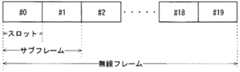
非特許文献1(5章)に記載される、3GPPでの、LTEシステムにおけるフレーム構成に関する決定事項について、図1を用いて説明する。図1は、LTE方式の通信システムで使用される無線フレームの構成を示す説明図である。図1において、1つの無線フレーム(Radio frame)は10msである。無線フレームは10個の等しい大きさのサブフレーム(Subframe)に分割される。サブフレームは、2個の等しい大きさのスロット(slot)に分割される。無線フレーム毎に1番目および6番目のサブフレームに下り同期信号(Downlink Synchronization Signal)が含まれる。同期信号には、第一同期信号(Primary Synchronization Signal:P−SS)と、第二同期信号(Secondary Synchronization Signal:S−SS)とがある。 The decisions regarding the frame configuration in the LTE system in 3GPP described in Non-Patent Document 1 (Chapter 5) will be described with reference to FIG. FIG. 1 is an explanatory diagram showing a configuration of a wireless frame used in an LTE communication system. In FIG. 1, one radio frame is 10 ms. The radio frame is divided into 10 equally sized subframes. The subframe is divided into two equally sized slots. A downlink synchronization signal is included in the first and sixth subframes for each radio frame. The synchronization signal includes a first synchronization signal (Primary Synchronization Signal: P-SS) and a second synchronization signal (Secondary Synchronization Signal: S-SS).
3GPPでの、LTEシステムにおけるチャネル構成に関する決定事項が、非特許文献1(5章)に記載されている。CSG(Closed Subscriber Group)セルにおいてもnon−CSGセルと同じチャネル構成が用いられると想定されている。 The decisions regarding the channel configuration in the LTE system in 3GPP are described in Non-Patent Document 1 (Chapter 5). It is assumed that the same channel configuration as the non-CSG cell is used in the CSG (Closed Subscriber Group) cell.
物理報知チャネル(Physical Broadcast Channel:PBCH)は、基地局装置(以下、単に「基地局」という場合がある)から移動端末装置(以下、単に「移動端末」という場合がある)などの通信端末装置(以下、単に「通信端末」という場合がある)への下り送信用のチャネルである。BCHトランスポートブロック(transport block)は、40ms間隔中の4個のサブフレームにマッピングされる。40msタイミングの明白なシグナリングはない。 The physical broadcast channel (PBCH) is a communication terminal device such as a base station device (hereinafter, may be simply referred to as a "base station") to a mobile terminal device (hereinafter, may be simply referred to as a "mobile terminal"). It is a channel for downlink transmission to (hereinafter, may be simply referred to as a "communication terminal"). The BCH transport block is mapped to 4 subframes in a 40 ms interval. There is no explicit signaling for 40ms timing.
物理制御フォーマットインジケータチャネル(Physical Control Format Indicator Channel:PCFICH)は、基地局から通信端末への下り送信用のチャネルである。PCFICHは、PDCCHsのために用いるOFDM(Orthogonal Frequency Division Multiplexing)シンボルの数を、基地局から通信端末へ通知する。PCFICHは、サブフレーム毎に送信される。 The Physical Control Format Indicator Channel (PCFICH) is a channel for downlink transmission from a base station to a communication terminal. PCFICH notifies the communication terminal from the base station of the number of OFDM (Orthogonal Frequency Division Multiplexing) symbols used for PDCCHs. PCFICH is transmitted every subframe.
物理下り制御チャネル(Physical Downlink Control Channel:PDCCH)は、基地局から通信端末への下り送信用のチャネルである。PDCCHは、後述のトランスポートチャネルの1つである下り共有チャネル(Downlink Shared Channel:DL−SCH)のリソース割り当て(allocation)情報、後述のトランスポートチャネルの1つであるページングチャネル(Paging Channel:PCH)のリソース割り当て(allocation)情報、DL−SCHに関するHARQ(Hybrid Automatic Repeat reQuest)情報を通知する。PDCCHは、上りスケジューリンググラント(Uplink Scheduling Grant)を運ぶ。PDCCHは、上り送信に対する応答信号であるAck(Acknowledgement)/Nack(Negative Acknowledgement)を運ぶ。PDCCHは、L1/L2制御信号とも呼ばれる。 The Physical Downlink Control Channel (PDCCH) is a channel for downlink transmission from a base station to a communication terminal. The PDCCH is a resource allocation information of a downlink shared channel (DL-SCH) which is one of the transport channels described later, and a paging channel (Paging Channel) which is one of the transport channels described later. ) Resource allocation information and HARQ (Hybrid Automatic Repeat reQuest) information related to DL-SCH are notified. The PDCCH carries an Uplink Scheduling Grant. The PDCCH carries Ac (Acknowledgement) / Nack (Negative Acknowledgement), which is a response signal for uplink transmission. The PDCCH is also called an L1 / L2 control signal.
物理下り共有チャネル(Physical Downlink Shared Channel:PDSCH)は、基地局から通信端末への下り送信用のチャネルである。PDSCHには、トランスポートチャネルである下り共有チャネル(DL−SCH)、およびトランスポートチャネルであるPCHがマッピングされている。 The Physical Downlink Shared Channel (PDSCH) is a channel for downlink transmission from a base station to a communication terminal. A downlink shared channel (DL-SCH), which is a transport channel, and a PCH, which is a transport channel, are mapped to the PDSCH.
物理マルチキャストチャネル(Physical Multicast Channel:PMCH)は、基地局から通信端末への下り送信用のチャネルである。PMCHには、トランスポートチャネルであるマルチキャストチャネル(Multicast Channel:MCH)がマッピングされている。 The physical multicast channel (PMCH) is a channel for downlink transmission from a base station to a communication terminal. A multicast channel (Multicast Channel: MCH), which is a transport channel, is mapped to the PMCH.
物理上り制御チャネル(Physical Uplink Control Channel:PUCCH)は、通信端末から基地局への上り送信用のチャネルである。PUCCHは、下り送信に対する応答信号(response signal)であるAck/Nackを運ぶ。PUCCHは、CQI(Channel Quality Indicator)レポートを運ぶ。CQIとは、受信したデータの品質、もしくは通信路品質を示す品質情報である。またPUCCHは、スケジューリングリクエスト(Scheduling Request:SR)を運ぶ。 The Physical Uplink Control Channel (PUCCH) is a channel for uplink transmission from a communication terminal to a base station. The PUCCH carries Ack / Nack, which is a response signal for downlink transmission. PUCCH carries a CQI (Channel Quality Indicator) report. CQI is quality information indicating the quality of received data or the quality of communication paths. The PUCCH also carries a scheduling request (SR).
物理上り共有チャネル(Physical Uplink Shared Channel:PUSCH)は、通信端末から基地局への上り送信用のチャネルである。PUSCHには、トランスポートチャネルの1つである上り共有チャネル(Uplink Shared Channel:UL−SCH)がマッピングされている。 The Physical Uplink Shared Channel (PUSCH) is a channel for uplink transmission from a communication terminal to a base station. An uplink shared channel (UL-SCH), which is one of the transport channels, is mapped to the PUSCH.
物理HARQインジケータチャネル(Physical Hybrid ARQ Indicator Channel:PHICH)は、基地局から通信端末への下り送信用のチャネルである。PHICHは、上り送信に対する応答信号であるAck/Nackを運ぶ。物理ランダムアクセスチャネル(Physical Random Access Channel:PRACH)は、通信端末から基地局への上り送信用のチャネルである。PRACHは、ランダムアクセスプリアンブル(random access preamble)を運ぶ。 The Physical Hybrid ARQ Indicator Channel (PHICH) is a channel for downlink transmission from a base station to a communication terminal. PHICH carries Ack / Nack, which is a response signal to uplink transmission. The Physical Random Access Channel (PRACH) is a channel for uplink transmission from a communication terminal to a base station. The PRACH carries a random access preamble.
下り参照信号(リファレンスシグナル(Reference Signal):RS)は、LTE方式の通信システムとして既知のシンボルである。以下の5種類の下りリファレンスシグナルが定義されている。セル固有参照信号(Cell-specific Reference Signal:CRS)、MBSFN参照信号(MBSFN Reference Signal)、UE固有参照信号(UE-specific Reference Signal)であるデータ復調用参照信号(Demodulation Reference Signal:DM−RS)、位置決定参照信号(Positioning Reference Signal:PRS)、チャネル状態情報参照信号(Channel State Information Reference Signal:CSI−RS)。通信端末の物理レイヤの測定として、リファレンスシグナルの受信電力(Reference Signal Received Power:RSRP)測定がある。 The downlink reference signal (Reference Signal (RS)) is a symbol known as an LTE communication system. The following five types of downlink reference signals are defined. Demodulation Reference Signal (DM-RS), which is a cell-specific reference signal (CRS), MBSFN reference signal (MBSFN Reference Signal), and UE-specific reference signal (UE-specific reference signal). , Positioning Reference Signal (PRS), Channel State Information Reference Signal (CSI-RS). As a measurement of the physical layer of a communication terminal, there is a reference signal received power (RSRP) measurement.
非特許文献1(5章)に記載されるトランスポートチャネル(Transport channel)について、説明する。下りトランスポートチャネルのうち、報知チャネル(Broadcast Channel:BCH)は、その基地局(セル)のカバレッジ全体に報知される。BCHは、物理報知チャネル(PBCH)にマッピングされる。 The transport channel described in Non-Patent Document 1 (Chapter 5) will be described. Of the downlink transport channels, the broadcast channel (BCH) is broadcast to the entire coverage of the base station (cell). BCH is mapped to the physical broadcast channel (PBCH).
下り共有チャネル(Downlink Shared Channel:DL−SCH)には、HARQ(Hybrid ARQ)による再送制御が適用される。DL−SCHは、基地局(セル)のカバレッジ全体への報知が可能である。DL−SCHは、ダイナミックあるいは準静的(Semi-static)なリソース割り当てをサポートする。準静的なリソース割り当ては、パーシステントスケジューリング(Persistent Scheduling)ともいわれる。DL−SCHは、通信端末の低消費電力化のために通信端末の間欠受信(Discontinuous reception:DRX)をサポートする。DL−SCHは、物理下り共有チャネル(PDSCH)へマッピングされる。 Retransmission control by HARQ (Hybrid ARQ) is applied to the downlink shared channel (DL-SCH). The DL-SCH can notify the entire coverage of the base station (cell). DL-SCH supports dynamic or quasi-static resource allocation. Quasi-static resource allocation is also known as Persistent Scheduling. The DL-SCH supports intermittent reception (DRX) of a communication terminal in order to reduce the power consumption of the communication terminal. The DL-SCH is mapped to a physical downlink shared channel (PDSCH).
ページングチャネル(Paging Channel:PCH)は、通信端末の低消費電力を可能とするために通信端末のDRXをサポートする。PCHは、基地局(セル)のカバレッジ全体への報知が要求される。PCHは、動的にトラフィックに利用できる物理下り共有チャネル(PDSCH)のような物理リソースへマッピングされる。 The paging channel (PCH) supports the DRX of a communication terminal to enable low power consumption of the communication terminal. The PCH is required to notify the entire coverage of the base station (cell). The PCH is dynamically mapped to a physical resource such as a physical downlink shared channel (PDSCH) available for traffic.
マルチキャストチャネル(Multicast Channel:MCH)は、基地局(セル)のカバレッジ全体への報知に使用される。MCHは、マルチセル送信におけるMBMS(Multimedia Broadcast Multicast Service)サービス(MTCHとMCCH)のSFN合成をサポートする。MCHは、準静的なリソース割り当てをサポートする。MCHは、PMCHへマッピングされる。 A multicast channel (MCH) is used to broadcast the entire coverage of a base station (cell). The MCH supports SFN synthesis of MBMS (Multimedia Broadcast Multicast Service) services (MTCH and MCCH) in multicell transmission. MCH supports quasi-static resource allocation. The MCH is mapped to the PMCH.
上りトランスポートチャネルのうち、上り共有チャネル(Uplink Shared Channel:UL−SCH)には、HARQ(Hybrid ARQ)による再送制御が適用される。UL−SCHは、ダイナミックあるいは準静的(Semi-static)なリソース割り当てをサポートする。UL−SCHは、物理上り共有チャネル(PUSCH)へマッピングされる。 Among the uplink transport channels, retransmission control by HARQ (Hybrid ARQ) is applied to the uplink shared channel (UL-SCH). UL-SCH supports dynamic or quasi-static resource allocation. UL-SCH is mapped to a physical uplink shared channel (PUSCH).
ランダムアクセスチャネル(Random Access Channel:RACH)は、制御情報に限られている。RACHは、衝突のリスクがある。RACHは、物理ランダムアクセスチャネル(PRACH)へマッピングされる。 Random Access Channel (RACH) is limited to control information. RACH is at risk of collision. The RACH is mapped to a Physical Random Access Channel (PRACH).
HARQについて説明する。HARQとは、自動再送要求(Automatic Repeat reQuest:ARQ)と誤り訂正(Forward Error Correction)との組合せによって、伝送路の通信品質を向上させる技術である。HARQには、通信品質が変化する伝送路に対しても、再送によって誤り訂正が有効に機能するという利点がある。特に、再送にあたって初送の受信結果と再送の受信結果との合成をすることで、更なる品質向上を得ることも可能である。 HARQ will be described. HARQ is a technique for improving the communication quality of a transmission line by combining an automatic repeat reQuest (ARQ) and an error correction (Forward Error Correction). HARQ has an advantage that error correction functions effectively by retransmission even for a transmission line whose communication quality changes. In particular, it is possible to further improve the quality by synthesizing the reception result of the first transmission and the reception result of the retransmission at the time of retransmission.
再送の方法の一例を説明する。受信側にて、受信データが正しくデコードできなかった場合、換言すればCRC(Cyclic Redundancy Check)エラーが発生した場合(CRC=NG)、受信側から送信側へ「Nack」を送信する。「Nack」を受信した送信側は、データを再送する。受信側にて、受信データが正しくデコードできた場合、換言すればCRCエラーが発生しない場合(CRC=OK)、受信側から送信側へ「Ack」を送信する。「Ack」を受信した送信側は次のデータを送信する。 An example of the retransmission method will be described. If the received data cannot be decoded correctly on the receiving side, in other words, if a CRC (Cyclic Redundancy Check) error occurs (CRC = NG), "Nack" is transmitted from the receiving side to the transmitting side. The transmitting side that receives the "Nack" retransmits the data. If the received data can be correctly decoded on the receiving side, in other words, if a CRC error does not occur (CRC = OK), "Ack" is transmitted from the receiving side to the transmitting side. The transmitting side that receives "Ack" transmits the next data.
非特許文献1(6章)に記載される論理チャネル(ロジカルチャネル:Logical channel)について、説明する。報知制御チャネル(Broadcast Control Channel:BCCH)は、報知システム制御情報のための下りチャネルである。論理チャネルであるBCCHは、トランスポートチャネルである報知チャネル(BCH)、あるいは下り共有チャネル(DL−SCH)へマッピングされる。 The logical channel (logical channel) described in Non-Patent Document 1 (Chapter 6) will be described. The broadcast control channel (BCCH) is a downlink channel for broadcast system control information. BCCH, which is a logical channel, is mapped to a broadcast channel (BCH), which is a transport channel, or a downlink shared channel (DL-SCH).
ページング制御チャネル(Paging Control Channel:PCCH)は、ページング情報(Paging Information)およびシステム情報(System Information)の変更を送信するための下りチャネルである。PCCHは、通信端末のセルロケーションをネットワークが知らない場合に用いられる。論理チャネルであるPCCHは、トランスポートチャネルであるページングチャネル(PCH)へマッピングされる。 The paging control channel (PCCH) is a downlink channel for transmitting changes in paging information (Paging Information) and system information (System Information). PCCH is used when the network does not know the cell location of the communication terminal. The PCCH, which is a logical channel, is mapped to a paging channel (PCH), which is a transport channel.
共有制御チャネル(Common Control Channel:CCCH)は、通信端末と基地局との間の送信制御情報のためのチャネルである。CCCHは、通信端末がネットワークとの間でRRC接続(connection)を有していない場合に用いられる。下り方向では、CCCHは、トランスポートチャネルである下り共有チャネル(DL−SCH)へマッピングされる。上り方向では、CCCHは、トランスポートチャネルである上り共有チャネル(UL−SCH)へマッピングされる。 A shared control channel (CCCH) is a channel for transmission control information between a communication terminal and a base station. CCCH is used when the communication terminal does not have an RRC connection with the network. In the downlink direction, the CCCH is mapped to the downlink shared channel (DL-SCH), which is a transport channel. In the uplink direction, the CCCH is mapped to the uplink shared channel (UL-SCH), which is a transport channel.
マルチキャスト制御チャネル(Multicast Control Channel:MCCH)は、1対多の送信のための下りチャネルである。MCCHは、ネットワークから通信端末への1つあるいはいくつかのMTCH用のMBMS制御情報の送信のために用いられる。MCCHは、MBMS受信中の通信端末のみに用いられる。MCCHは、トランスポートチャネルであるマルチキャストチャネル(MCH)へマッピングされる。 The Multicast Control Channel (MCCH) is a downlink channel for one-to-many transmission. The MCCH is used for transmitting MBMS control information for one or several MTCHs from the network to the communication terminal. MCCH is used only for communication terminals receiving MBMS. The MCCH is mapped to a multicast channel (MCH), which is a transport channel.
個別制御チャネル(Dedicated Control Channel:DCCH)は、1対1にて、通信端末とネットワークとの間の個別制御情報を送信するチャネルである。DCCHは、通信端末がRRC接続(connection)である場合に用いられる。DCCHは、上りでは上り共有チャネル(UL−SCH)へマッピングされ、下りでは下り共有チャネル(DL−SCH)にマッピングされる。 The individual control channel (Dedicated Control Channel: DCCH) is a channel for transmitting individual control information between the communication terminal and the network on a one-to-one basis. The DCCH is used when the communication terminal is an RRC connection. The DCCH is mapped to the uplink shared channel (UL-SCH) on the uplink and to the downlink shared channel (DL-SCH) on the downlink.
個別トラフィックチャネル(Dedicated Traffic Channel:DTCH)は、ユーザ情報の送信のための個別通信端末への1対1通信のチャネルである。DTCHは、上りおよび下りともに存在する。DTCHは、上りでは上り共有チャネル(UL−SCH)へマッピングされ、下りでは下り共有チャネル(DL−SCH)へマッピングされる。 The Dedicated Traffic Channel (DTCH) is a channel for one-to-one communication to an individual communication terminal for transmitting user information. DTCH exists both up and down. The DTCH is mapped to the uplink shared channel (UL-SCH) on the uplink and to the downlink shared channel (DL-SCH) on the downlink.
マルチキャストトラフィックチャネル(Multicast Traffic channel:MTCH)は、ネットワークから通信端末へのトラフィックデータ送信のための下りチャネルである。MTCHは、MBMS受信中の通信端末のみに用いられるチャネルである。MTCHは、マルチキャストチャネル(MCH)へマッピングされる。 A multicast traffic channel (MTCH) is a downlink channel for transmitting traffic data from a network to a communication terminal. MTCH is a channel used only for communication terminals receiving MBMS. The MTCH is mapped to a multicast channel (MCH).
CGIとは、セルグローバル識別子(Cell Global Identifier)のことである。ECGIとは、E−UTRANセルグローバル識別子(E-UTRAN Cell Global Identifier)のことである。LTE、後述のLTE−A(Long Term Evolution Advanced)およびUMTS(Universal Mobile Telecommunication System)において、CSG(Closed Subscriber Group)セルが導入される。 CGI is a Cell Global Identifier. The ECGI is an E-UTRAN Cell Global Identifier. CSG (Closed Subscriber Group) cells are introduced in LTE, LTE-A (Long Term Evolution Advanced) and UMTS (Universal Mobile Telecommunication System), which will be described later.
CSG(Closed Subscriber Group)セルとは、利用可能な加入者をオペレータが特定しているセル(以下「特定加入者用セル」という場合がある)である。特定された加入者は、PLMN(Public Land Mobile Network)の1つ以上のセルにアクセスすることが許可される。特定された加入者がアクセスを許可されている1つ以上のセルを「CSGセル(CSG cell(s))」と呼ぶ。ただし、PLMNにはアクセス制限がある。 The CSG (Closed Subscriber Group) cell is a cell in which an operator specifies available subscribers (hereinafter, may be referred to as a "specific subscriber cell"). Identified subscribers are allowed access to one or more cells in the PLMN (Public Land Mobile Network). One or more cells that the identified subscriber is granted access to are called "CSG cells (CSG cells)". However, PLMN has access restrictions.
CSGセルは、固有のCSGアイデンティティ(CSG identity:CSG ID;CSG−ID)を報知し、CSGインジケーション(CSG Indication)にて「TRUE」を報知するPLMNの一部である。予め利用登録し、許可された加入者グループのメンバーは、アクセス許可情報であるところのCSG−IDを用いてCSGセルにアクセスする。 The CSG cell is a part of PLMN that notifies a unique CSG identity (CSG identity: CSG ID; CSG-ID) and notifies "TRUE" by CSG Indication. Members of the subscriber group who have been registered for use in advance and are authorized access the CSG cell using the CSG-ID which is the access permission information.
CSG−IDは、CSGセルまたはセルによって報知される。LTE方式の通信システムにCSG−IDは複数存在する。そして、CSG−IDは、CSG関連のメンバーのアクセスを容易にするために、通信端末(UE)によって使用される。 The CSG-ID is announced by the CSG cell or cell. There are a plurality of CSG-IDs in the LTE communication system. The CSG-ID is then used by the communication terminal (UE) to facilitate access for CSG-related members.
通信端末の位置追跡は、1つ以上のセルからなる区域を単位に行われる。位置追跡は、待受け状態であっても通信端末の位置を追跡し、通信端末を呼び出す、換言すれば通信端末が着呼することを可能にするために行われる。この通信端末の位置追跡のための区域をトラッキングエリアと呼ぶ。 The position tracking of the communication terminal is performed in units of areas consisting of one or more cells. The position tracking is performed to track the position of the communication terminal even in the standby state and call the communication terminal, in other words, to enable the communication terminal to make a call. The area for tracking the position of this communication terminal is called a tracking area.
3GPPにおいて、Home−NodeB(Home−NB;HNB)、Home−eNodeB(Home−eNB;HeNB)と称される基地局が検討されている。UTRANにおけるHNB、およびE−UTRANにおけるHeNBは、例えば家庭、法人、商業用のアクセスサービス向けの基地局である。非特許文献2には、HeNBおよびHNBへのアクセスの3つの異なるモードが開示されている。具体的には、オープンアクセスモード(Open access mode)と、クローズドアクセスモード(Closed access mode)と、ハイブリッドアクセスモード(Hybrid access mode)とが開示されている。 In 3GPP, base stations called Home-NodeB (Home-NB; HNB) and Home-eNodeB (Home-eNB; HeNB) are being studied. The HNB in UTRAN and the HeNB in E-UTRAN are, for example, base stations for home, corporate, and commercial access services.
各々のモードは、以下のような特徴を有する。オープンアクセスモードでは、HeNBおよびHNBは、通常のオペレータのノーマルセルとして操作される。クローズドアクセスモードでは、HeNBおよびHNBは、CSGセルとして操作される。このCSGセルは、CSGメンバーのみアクセス可能なCSGセルである。ハイブリッドアクセスモードでは、HeNBおよびHNBは、非CSGメンバーも同時にアクセス許可されているCSGセルとして操作される。言い換えれば、ハイブリッドアクセスモードのセル(ハイブリッドセルとも称する)は、オープンアクセスモードとクローズドアクセスモードとの両方をサポートするセルである。 Each mode has the following features. In open access mode, HeNB and HNB are operated as normal cells of a normal operator. In closed access mode, HeNB and HNB are operated as CSG cells. This CSG cell is a CSG cell that can be accessed only by CSG members. In hybrid access mode, HeNB and HNB are operated as CSG cells to which non-CSG members are also allowed access at the same time. In other words, a cell in hybrid access mode (also referred to as a hybrid cell) is a cell that supports both open access mode and closed access mode.
3GPPでは、全ての物理セル識別子(Physical Cell Identity:PCI)のうち、CSGセルで使用するためにネットワークによって予約されたPCI範囲がある(非特許文献1 10.5.1.1章参照)。PCI範囲を分割することをPCIスプリットと称することがある。PCIスプリットに関する情報(PCIスプリット情報とも称する)は、システム情報によって基地局から傘下の通信端末に対して報知される。基地局の傘下とは、該基地局をサービングセルとすることを意味する。 In 3GPP, of all Physical Cell Identity (PCI), there is a PCI range reserved by the network for use in CSG cells (see
非特許文献3は、PCIスプリットを用いた通信端末の基本動作を開示する。PCIスプリット情報を有していない通信端末は、全PCIを用いて、例えば504コード全てを用いて、セルサーチを行う必要がある。これに対して、PCIスプリット情報を有する通信端末は、当該PCIスプリット情報を用いてセルサーチを行うことが可能である。 Non-Patent Document 3 discloses a basic operation of a communication terminal using a PCI split. A communication terminal that does not have PCI split information needs to perform a cell search using all PCIs, for example, all 504 codes. On the other hand, a communication terminal having PCI split information can perform a cell search using the PCI split information.
また3GPPでは、リリース10として、ロングタームエボリューションアドヴァンスド(Long Term Evolution Advanced:LTE−A)の規格策定が進められている(非特許文献4、非特許文献5参照)。LTE−Aは、LTEの無線区間通信方式を基本とし、それにいくつかの新技術を加えて構成される。 In 3GPP, as Release 10, the standard for Long Term Evolution Advanced (LTE-A) is being formulated (see Non-Patent Document 4 and Non-Patent Document 5). LTE-A is based on the LTE radio section communication system, and is configured by adding some new technologies to it.
LTE−Aシステムでは、100MHzまでのより広い周波数帯域幅(transmission bandwidths)をサポートするために、二つ以上のコンポーネントキャリア(Component Carrier:CC)を集約する(「アグリゲーション(aggregation)する」とも称する)、キャリアアグリゲーション(Carrier Aggregation:CA)が検討されている。 In LTE-A systems, two or more Component Carriers (CCs) are aggregated (also referred to as "aggregation") to support wider transmission bandwidths up to 100 MHz. , Carrier Aggregation (CA) is being considered.
CAが構成される場合、UEはネットワーク(Network:NW)と唯一つのRRC接続(RRC connection)を有する。RRC接続において、一つのサービングセルがNASモビリティ情報とセキュリティ入力を与える。このセルをプライマリセル(Primary Cell:PCell)と呼ぶ。下りリンクで、PCellに対応するキャリアは、下りプライマリコンポーネントキャリア(Downlink Primary Component Carrier:DL PCC)である。上りリンクで、PCellに対応するキャリアは、上りプライマリコンポーネントキャリア(Uplink Primary Component Carrier:UL PCC)である。 When the CA is configured, the UE has a network (NW) and only one RRC connection (RRC connection). In the RRC connection, one serving cell provides NAS mobility information and security inputs. This cell is called a primary cell (PCell). In the downlink, the carrier corresponding to the PCell is the downlink primary component carrier (DL PCC). The carrier corresponding to the PCell in the uplink is the Uplink Primary Component Carrier (UL PCC).
UEの能力(ケーパビリティ(capability))に応じて、セカンダリセル(Secondary Cell:SCell)が、PCellとサービングセルの組を形成するために構成される。下りリンクで、SCellに対応するキャリアは、下りセカンダリコンポーネントキャリア(Downlink Secondary Component Carrier:DL SCC)である。上りリンクで、SCellに対応するキャリアは、上りセカンダリコンポーネントキャリア(Uplink Secondary Component Carrier:UL SCC)である。 Depending on the capability of the UE, a secondary cell (SCell) is configured to form a pair of PCell and serving cell. In the downlink, the carrier corresponding to SCell is the downlink secondary component carrier (DL SCC). The carrier corresponding to SCell in the uplink is the Uplink Secondary Component Carrier (UL SCC).
一つのUEに対して、一つのPCellと、一つ以上のSCellとからなるサービングセルの組が構成される。 For one UE, a set of serving cells including one PCell and one or more SCells is configured.
また、LTE−Aでの新技術としては、より広い帯域をサポートする技術(Wider bandwidth extension)、および多地点協調送受信(Coordinated Multiple Point transmission and reception:CoMP)技術などがある。3GPPでLTE−Aのために検討されているCoMPについては、非特許文献6に記載されている。 In addition, new technologies in LTE-A include a technology for supporting a wider bandwidth (Wider bandwidth extension) and a technology for coordinated multiple point transmission and reception (CoMP). CoMP being studied for LTE-A in 3GPP is described in Non-Patent Document 6.
モバイルネットワークのトラフィック量は、増加傾向にあり、通信速度も高速化が進んでいる。LTEおよびLTE−Aが本格的に運用を開始されると、更に通信速度が高速化され、トラフィック量が増加することが見込まれる。 The traffic volume of mobile networks is on the rise, and the communication speed is also increasing. When LTE and LTE-A start full-scale operation, it is expected that the communication speed will be further increased and the traffic volume will increase.
また、スマートフォンおよびタブレット型端末装置の普及によって、セルラー系無線通信によるトラフィック量が爆発的に増加しており、世界中で無線リソースの不足が懸念されている。 In addition, with the spread of smartphones and tablet terminals, the amount of traffic due to cellular wireless communication is increasing explosively, and there are concerns about the shortage of wireless resources all over the world.
トラフィック量の増加の問題に対して、3GPPにおいて、リリース12版の規格書の策定が進められている。リリース12版の規格書では、将来の膨大なトラフィック量に対応するために、スモールeNBを用いることが検討されている。例えば、多数のスモールeNBを設置して、多数のスモールセルを構成することによって、周波数利用効率を高めて、通信容量の増大を図る技術などが検討されている。 In response to the problem of increased traffic volume, the 12th release version of the standard is being developed in 3GPP. The release 12 version of the standard considers the use of small eNBs to handle the enormous traffic volume in the future. For example, a technique for increasing frequency utilization efficiency and increasing communication capacity by installing a large number of small eNBs and configuring a large number of small cells is being studied.
その中で、マクロセルとスモールセルとがオーバラップしている場合に、通信端末がマクロセルとスモールセルとの両方に接続する技術として、デュアルコネクティビティ(dual connectivity)が議論されている(非特許文献8参照)。非特許文献8には、マクロセルとスモールセルとがオーバラップしている場合に、通信端末がマクロセルとスモールセルとの両方に接続する技術として、デュアルコネクティビティ(dual connectivity)が開示されている。 Among them, dual connectivity has been discussed as a technique for connecting a communication terminal to both a macro cell and a small cell when the macro cell and the small cell overlap (Non-Patent Document 8). reference). Non-Patent Document 8 discloses dual connectivity as a technique for connecting a communication terminal to both the macro cell and the small cell when the macro cell and the small cell overlap.
さらに、高度化する移動体通信に対して、2020年以降にサービスを開始することを目標とした第5世代(以下「5G」という場合がある)無線アクセスシステムが検討されている。例えば、欧州では、METISという団体で5Gの要求事項がまとめられている(非特許文献9参照)。 Further, for the increasingly sophisticated mobile communication, a fifth generation (hereinafter sometimes referred to as "5G") wireless access system with the goal of starting the service after 2020 is being studied. For example, in Europe, the requirements for 5G are summarized by an organization called METIS (see Non-Patent Document 9).
5G無線アクセスシステムでは、LTEシステムと比較して、システム容量は1000倍、データ伝送速度は100倍、データ処理遅延は10分の1(1/10)、通信端末の同時接続数は100倍として、更なる低消費電力化、および装置の低コスト化を実現することが要件として挙げられている。 In the 5G wireless access system, the system capacity is 1000 times, the data transmission speed is 100 times, the data processing delay is 1/10 (1/10), and the number of simultaneous connections of communication terminals is 100 times that of the LTE system. , Further reduction in power consumption and cost reduction of the equipment are listed as requirements.
このような要件を満たすために、周波数を広帯域で使用してデータの伝送容量を増やすこと、ならびに周波数利用効率を上げてデータの伝送速度を上げるために、空間多重を可能とする、多素子アンテナを用いたMIMO(Multiple Input Multiple Output)およびビームフォーミングなどの技術が検討されている。 Multi-element antennas that enable spatial multiplexing to meet these requirements by using wideband frequencies to increase data transmission capacity and to increase frequency utilization efficiency and data transmission speed. Techniques such as MIMO (Multiple Input Multiple Output) and beamforming using the above are being studied.
同じ無線アクセス技術(Radio Access Technology;略称:RAT)または異なるRATの2つのセルがオーバラップしている場合に、通信端末が両方のセルとデュアルコネクティビティ(dual connectivity)およびキャリアアグリゲーション(carrier aggregation)のいずれで接続するかを切り替える技術として、マルチコネクティビティ(multi-connectivity)が議論されている(例えば、「RWS−150023,Intel,3GPP RAN 5G Workshop 2015年9月19日」参照)。 When two cells of the same Radio Access Technology (abbreviation: RAT) or different RATs overlap, the communication terminal has dual connectivity and carrier aggregation with both cells. Multi-connectivity is being discussed as a technology for switching which connection is used (see, for example, "RWS-150023, Intel,
セルと通信端末との接続形態を、デュアルコネクティビティおよびキャリアアグリゲーションのいずれにするかを選択するパラメータの1つとして、バックホールの性能が考えられている。 Backhaul performance is considered as one of the parameters for selecting whether the connection form between the cell and the communication terminal is dual connectivity or carrier aggregation.
バックホールの性能については、例えば、3GPP TR 36.932(以下「参考文献1」という)に記載されている。参考文献1では、遅延およびスループットに基づいて分類される理想的バックホール(ideal backhaul)と非理想的バックホール(non-ideal backhaul)とについて記載されている。しかしながら、参考文献1では、バックホールの性能の測定、およびその性能に応じたマルチコネクティビティを行うことについては、何ら開示も示唆もされていない。 The performance of the backhaul is described, for example, in 3GPP TR 36.923 (hereinafter referred to as "
性能の測定については、例えば、3GPP TS 36.314(以下「参考文献2」という)に記載されている。参考文献2では、通信端末と基地局との間のレイヤ2における各種性能の測定に関する仕様が規定されている。しかしながら、参考文献2では、バックホールにおける測定、およびマルチコネクティビティへの適用については、何ら開示も示唆もされていない。 Performance measurements are described, for example, in 3GPP TS 36.314 (hereinafter referred to as "
本発明の目的は、通信端末装置と基地局装置との接続形態を、異なる複数の接続形態の中から適切に選択することができる通信システムを提供することである。 An object of the present invention is to provide a communication system capable of appropriately selecting a connection form between a communication terminal device and a base station device from a plurality of different connection forms.
本発明の通信システムは、通信端末装置と、前記通信端末装置と無線通信可能に接続される複数の基地局装置と、前記通信端末装置と各前記基地局装置との通信を管理するコアネットワークとを備える通信システムであって、前記通信端末装置と前記複数の基地局装置とは、異なる複数の接続形態によって接続可能であり、前記複数の基地局装置のうちで前記通信端末装置からメジャメント報告を受信した基地局装置は、前記複数の接続形態のうち、いずれの接続形態を選択するかを、少なくとも、前記基地局装置同士を接続するリンクの遅延の測定結果に基づいて決定することを特徴とする。The communication system of the present invention includes a communication terminal device, a plurality of base station devices that are wirelessly connected to the communication terminal device, and a core network that manages communication between the communication terminal device and each of the base station devices. The communication terminal device and the plurality of base station devices can be connected by a plurality of different connection forms, and thecommunication terminal device among the plurality of base station devices canreport a measurement. received base station apparatus, among the plurality of connection forms,whether to select one of the topology, at least, and characterized bydetermining based on the measurement result of the delay of the link connecting the base station apparatus to each other To do.
本発明の通信システムによれば、通信端末装置と複数の基地局装置とコアネットワークとを備えて、通信システムが構成される。通信端末装置と複数の基地局装置とは、異なる複数の接続形態によって接続可能である。複数の基地局装置のうちで通信端末装置からメジャメント報告を受信した基地局装置は、複数の接続形態のうち、いずれの接続形態を選択するかを、少なくとも、基地局装置同士を接続するリンクの遅延の測定結果に基づいて決定する。これによって、通信端末装置と基地局装置との接続形態を、異なる複数の接続形態の中から適切に選択することができる。
According to the communication system of the present invention, a communication system is configured by including a communication terminal device, a plurality of base station devices, and a core network. The communication terminal device and the plurality of base station devices can be connected by a plurality of different connection forms.Among a plurality of base station devices, the base station device that has received the measurement report from the communication terminal device determineswhich connection form to select from the plurality of connection forms, at least for the link connecting the base station devices. Determined based on the delay measurement results. Thereby, the connection form between the communication terminal device and the base station device can be appropriately selected from a plurality of different connection forms.
実施の形態1.
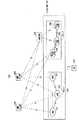
図2は、3GPPにおいて議論されているLTE方式の通信システム200の全体的な構成を示すブロック図である。図2について説明する。無線アクセスネットワークは、E−UTRAN(Evolved Universal Terrestrial Radio Access Network)201と称される。通信端末装置である移動端末装置(以下「移動端末(User Equipment:UE)」という)202は、基地局装置(以下「基地局(E-UTRAN NodeB:eNB)」という)203と無線通信可能であり、無線通信で信号の送受信を行う。
FIG. 2 is a block diagram showing the overall configuration of the
ここで、「通信端末装置」とは、移動可能な携帯電話端末装置などの移動端末装置だけでなく、センサなどの移動しないデバイスも含んでいる。以下の説明では、「通信端末装置」を、単に「通信端末」という場合がある。 Here, the "communication terminal device" includes not only a mobile terminal device such as a mobile mobile phone terminal device but also a non-moving device such as a sensor. In the following description, the "communication terminal device" may be simply referred to as a "communication terminal".
移動端末202に対する制御プロトコル、例えばRRC(Radio Resource Control)と、ユーザプレイン、例えばPDCP(Packet Data Convergence Protocol)、RLC(Radio Link Control)、MAC(Medium Access Control)、PHY(Physical layer)とが基地局203で終端するならば、E−UTRANは1つあるいは複数の基地局203によって構成される。 Control protocols for
移動端末202と基地局203との間の制御プロトコルRRC(Radio Resource Control)は、報知(Broadcast)、ページング(paging)、RRC接続マネージメント(RRC connection management)などを行う。RRCにおける基地局203と移動端末202との状態として、RRC_IDLEと、RRC_CONNECTEDとがある。 The control protocol RRC (Radio Resource Control) between the
RRC_IDLEでは、PLMN(Public Land Mobile Network)選択、システム情報(System Information:SI)の報知、ページング(paging)、セル再選択(cell re-selection)、モビリティなどが行われる。RRC_CONNECTEDでは、移動端末はRRC接続(connection)を有し、ネットワークとのデータの送受信を行うことができる。またRRC_CONNECTEDでは、ハンドオーバ(Handover:HO)、隣接セル(Neighbour cell)の測定(メジャメント(measurement))などが行われる。 In RRC_IDLE, PLMN (Public Land Mobile Network) selection, system information (SI) notification, paging, cell re-selection, mobility, and the like are performed. In RRC_CONNECTED, the mobile terminal has an RRC connection and can send and receive data to and from the network. Further, in RRC_CONCEPTED, handover (HO), measurement of adjacent cells (neighbor cell), and the like are performed.
基地局203は、eNB207と、Home−eNB206とに分類される。通信システム200は、複数のeNB207を含むeNB群203−1と、複数のHome−eNB206を含むHome−eNB群203−2とを備える。またコアネットワークであるEPC(Evolved Packet Core)と、無線アクセスネットワークであるE−UTRAN201とで構成されるシステムは、EPS(Evolved Packet System)と称される。コアネットワークであるEPCと、無線アクセスネットワークであるE−UTRAN201とを合わせて、「ネットワーク」という場合がある。
eNB207は、移動管理エンティティ(Mobility Management Entity:MME)、あるいはS−GW(Serving Gateway)、あるいはMMEおよびS−GWを含むMME/S−GW部(以下「MME部」という場合がある)204とS1インタフェースにより接続され、eNB207とMME部204との間で制御情報が通信される。一つのeNB207に対して、複数のMME部204が接続されてもよい。eNB207間は、X2インタフェースにより接続され、eNB207間で制御情報が通信される。 The
Home−eNB206は、MME部204とS1インタフェースにより接続され、Home−eNB206とMME部204との間で制御情報が通信される。一つのMME部204に対して、複数のHome−eNB206が接続される。あるいは、Home−eNB206は、HeNBGW(Home-eNB GateWay)205を介してMME部204と接続される。Home−eNB206とHeNBGW205とは、S1インタフェースにより接続され、HeNBGW205とMME部204とはS1インタフェースを介して接続される。 The Home-
一つまたは複数のHome−eNB206が一つのHeNBGW205と接続され、S1インタフェースを通して情報が通信される。HeNBGW205は、一つまたは複数のMME部204と接続され、S1インタフェースを通して情報が通信される。 One or more Home-eNB 206s are connected to one HeNBGW 205 and information is communicated through the S1 interface. The
MME部204およびHeNBGW205は、上位装置、具体的には上位ノードであり、基地局であるeNB207およびHome−eNB206と、移動端末(UE)202との接続を制御する。MME部204は、コアネットワークであるEPCを構成する。基地局203およびHeNBGW205は、E−UTRAN201を構成する。 The
さらに3GPPでは、以下のような構成が検討されている。Home−eNB206間のX2インタフェースはサポートされる。すなわち、Home−eNB206間は、X2インタフェースにより接続され、Home−eNB206間で制御情報が通信される。MME部204からは、HeNBGW205はHome−eNB206として見える。Home−eNB206からは、HeNBGW205はMME部204として見える。 Furthermore, in 3GPP, the following configurations are being considered. The X2 interface between Home-
Home−eNB206が、HeNBGW205を介してMME部204に接続される場合および直接MME部204に接続される場合のいずれの場合も、Home−eNB206とMME部204との間のインタフェースは、S1インタフェースで同じである。 In both cases where the Home-
基地局203は、1つのセルを構成してもよいし、複数のセルを構成してもよい。各セルは、移動端末202と通信可能な範囲であるカバレッジとして予め定める範囲を有し、カバレッジ内で移動端末202と無線通信を行う。1つの基地局203が複数のセルを構成する場合、1つ1つのセルが、移動端末202と通信可能に構成される。 The
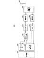
図3は、本発明に係る通信端末である図2に示す移動端末202の構成を示すブロック図である。図3に示す移動端末202の送信処理を説明する。まず、プロトコル処理部301からの制御データ、およびアプリケーション部302からのユーザデータが、送信データバッファ部303へ保存される。送信データバッファ部303に保存されたデータは、エンコーダー部304へ渡され、誤り訂正などのエンコード処理が施される。エンコード処理を施さずに、送信データバッファ部303から変調部305へ直接出力されるデータが存在してもよい。エンコーダー部304でエンコード処理されたデータは、変調部305にて変調処理が行われる。変調されたデータは、ベースバンド信号に変換された後、周波数変換部306へ出力され、無線送信周波数に変換される。その後、アンテナ307から基地局203に送信信号が送信される。 FIG. 3 is a block diagram showing a configuration of a
また、移動端末202の受信処理は、以下のように実行される。基地局203からの無線信号がアンテナ307により受信される。受信信号は、周波数変換部306にて無線受信周波数からベースバンド信号に変換され、復調部308において復調処理が行われる。復調後のデータは、デコーダー部309へ渡され、誤り訂正などのデコード処理が行われる。デコードされたデータのうち、制御データはプロトコル処理部301へ渡され、ユーザデータはアプリケーション部302へ渡される。移動端末202の一連の処理は、制御部310によって制御される。よって制御部310は、図3では省略しているが、各部301〜309と接続している。 Further, the reception process of the
図4は、本発明に係る基地局である図2に示す基地局203の構成を示すブロック図である。図4に示す基地局203の送信処理を説明する。EPC通信部401は、基地局203とEPC(MME部204など)、HeNBGW205などとの間のデータの送受信を行う。他基地局通信部402は、他の基地局との間のデータの送受信を行う。EPC通信部401および他基地局通信部402は、それぞれプロトコル処理部403と情報の受け渡しを行う。プロトコル処理部403からの制御データ、ならびにEPC通信部401および他基地局通信部402からのユーザデータおよび制御データは、送信データバッファ部404へ保存される。 FIG. 4 is a block diagram showing the configuration of the
送信データバッファ部404に保存されたデータは、エンコーダー部405へ渡され、誤り訂正などのエンコード処理が施される。エンコード処理を施さずに、送信データバッファ部404から変調部406へ直接出力されるデータが存在してもよい。エンコードされたデータは、変調部406にて変調処理が行われる。変調されたデータは、ベースバンド信号に変換された後、周波数変換部407へ出力され、無線送信周波数に変換される。その後、アンテナ408より一つもしくは複数の移動端末202に対して送信信号が送信される。 The data stored in the transmission
また、基地局203の受信処理は以下のように実行される。一つもしくは複数の移動端末202からの無線信号が、アンテナ408により受信される。受信信号は、周波数変換部407にて無線受信周波数からベースバンド信号に変換され、復調部409で復調処理が行われる。復調されたデータは、デコーダー部410へ渡され、誤り訂正などのデコード処理が行われる。デコードされたデータのうち、制御データはプロトコル処理部403あるいはEPC通信部401、他基地局通信部402へ渡され、ユーザデータはEPC通信部401および他基地局通信部402へ渡される。基地局203の一連の処理は、制御部411によって制御される。よって制御部411は、図4では省略しているが、各部401〜410と接続している。 Further, the reception process of the
図5は、本発明に係るMMEの構成を示すブロック図である。図5では、前述の図2に示すMME部204に含まれるMME204aの構成を示す。PDN GW通信部501は、MME204aとPDN GWとの間のデータの送受信を行う。基地局通信部502は、MME204aと基地局203との間のS1インタフェースによるデータの送受信を行う。PDN GWから受信したデータがユーザデータであった場合、ユーザデータは、PDN GW通信部501から、ユーザプレイン通信部503経由で基地局通信部502に渡され、1つあるいは複数の基地局203へ送信される。基地局203から受信したデータがユーザデータであった場合、ユーザデータは、基地局通信部502から、ユーザプレイン通信部503経由でPDN GW通信部501に渡され、PDN GWへ送信される。 FIG. 5 is a block diagram showing the configuration of the MME according to the present invention. FIG. 5 shows the configuration of the
PDN GWから受信したデータが制御データであった場合、制御データは、PDN GW通信部501から制御プレイン制御部505へ渡される。基地局203から受信したデータが制御データであった場合、制御データは、基地局通信部502から制御プレイン制御部505へ渡される。 When the data received from the PDN GW is the control data, the control data is passed from the PDN
HeNBGW通信部504は、HeNBGW205が存在する場合に設けられ、情報種別によって、MME204aとHeNBGW205との間のインタフェース(IF)によるデータの送受信を行う。HeNBGW通信部504から受信した制御データは、HeNBGW通信部504から制御プレイン制御部505へ渡される。制御プレイン制御部505での処理の結果は、PDN GW通信部501経由でPDN GWへ送信される。また、制御プレイン制御部505で処理された結果は、基地局通信部502経由でS1インタフェースにより1つあるいは複数の基地局203へ送信され、またHeNBGW通信部504経由で1つあるいは複数のHeNBGW205へ送信される。 The
制御プレイン制御部505には、NASセキュリティ部505−1、SAEベアラコントロール部505−2、アイドルステート(Idle State)モビリティ管理部505−3などが含まれ、制御プレインに対する処理全般を行う。NASセキュリティ部505−1は、NAS(Non-Access Stratum)メッセージのセキュリティなどを行う。SAEベアラコントロール部505−2は、SAE(System Architecture Evolution)のベアラの管理などを行う。アイドルステートモビリティ管理部505−3は、待受け状態(アイドルステート(Idle State);LTE−IDLE状態、または、単にアイドルとも称される)のモビリティ管理、待受け状態時のページング信号の生成および制御、傘下の1つあるいは複数の移動端末202のトラッキングエリアの追加、削除、更新、検索、トラッキングエリアリスト管理などを行う。 The control
MME204aは、1つまたは複数の基地局203に対して、ページング信号の分配を行う。また、MME204aは、待受け状態(Idle State)のモビリティ制御(Mobility control)を行う。MME204aは、移動端末が待ち受け状態のとき、および、アクティブ状態(Active State)のときに、トラッキングエリア(Tracking Area)リストの管理を行う。MME204aは、UEが登録されている(registered)追跡領域(トラッキングエリア:Tracking Area)に属するセルへ、ページングメッセージを送信することで、ページングプロトコルに着手する。MME204aに接続されるHome−eNB206のCSGの管理およびCSG−IDの管理、そしてホワイトリスト管理は、アイドルステートモビリティ管理部505−3で行われてもよい。 The
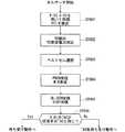
次に通信システムにおけるセルサーチ方法の一例を示す。図6は、LTE方式の通信システムにおいて通信端末(UE)が行うセルサーチから待ち受け動作までの概略を示すフローチャートである。通信端末は、セルサーチを開始すると、ステップST601で、周辺の基地局から送信される第一同期信号(P−SS)、および第二同期信号(S−SS)を用いて、スロットタイミング、フレームタイミングの同期をとる。 Next, an example of the cell search method in the communication system will be shown. FIG. 6 is a flowchart showing an outline from a cell search to a standby operation performed by a communication terminal (UE) in an LTE communication system. When the communication terminal starts the cell search, in step ST601, the slot timing and the frame are used by using the first synchronization signal (P-SS) and the second synchronization signal (S-SS) transmitted from the surrounding base stations. Synchronize the timing.
P−SSとS−SSとを合わせて、同期信号(Synchronization Signal:SS)という。同期信号(SS)には、セル毎に割り当てられたPCIに1対1に対応するシンクロナイゼーションコードが割り当てられている。PCIの数は504通りが検討されている。この504通りのPCIを用いて同期をとるとともに、同期がとれたセルのPCIを検出(特定)する。 The P-SS and S-SS are collectively called a synchronization signal (SS). A synchronization code corresponding to one-to-one is assigned to the PCI assigned to each cell in the synchronization signal (SS). 504 different types of PCI are being considered. The PCIs of the synchronized cells are detected (specified) while synchronizing using the 504 types of PCIs.
次に同期がとれたセルに対して、ステップST602で、基地局からセル毎に送信される参照信号(リファレンスシグナル:RS)であるセル固有参照信号(Cell-specific Reference Signal:CRS)を検出し、RSの受信電力(Reference Signal Received Power:RSRP)の測定を行う。参照信号(RS)には、PCIと1対1に対応したコードが用いられている。そのコードで相関をとることによって他セルと分離できる。ステップST1で特定したPCIから、該セルのRS用のコードを導出することによって、RSを検出し、RSの受信電力を測定することが可能となる。 Next, for the synchronized cells, in step ST602, a cell-specific reference signal (CRS), which is a reference signal (reference signal: RS) transmitted from the base station to each cell, is detected. , RS receive power (Reference Signal Received Power: RSRP) is measured. For the reference signal (RS), a code having a one-to-one correspondence with PCI is used. It can be separated from other cells by correlating with that code. By deriving the code for RS of the cell from the PCI identified in step ST1, RS can be detected and the received power of RS can be measured.
次にステップST603で、ステップST602までで検出された一つ以上のセルの中から、RSの受信品質が最もよいセル、例えば、RSの受信電力が最も高いセル、つまりベストセルを選択する。 Next, in step ST603, the cell with the highest RS reception quality, for example, the cell with the highest RS reception power, that is, the best cell is selected from the one or more cells detected up to step ST602.
次にステップST604で、ベストセルのPBCHを受信して、報知情報であるBCCHを得る。PBCH上のBCCHには、セル構成情報が含まれるMIB(Master Information Block)がマッピングされる。したがって、PBCHを受信してBCCHを得ることで、MIBが得られる。MIBの情報としては、例えば、DL(ダウンリンク)システム帯域幅(送信帯域幅設定(transmission bandwidth configuration:dl-bandwidth)とも呼ばれる)、送信アンテナ数、SFN(System Frame Number)などがある。 Next, in step ST604, the best cell PBCH is received to obtain BCCH which is broadcast information. A MIB (Master Information Block) including cell configuration information is mapped to the BCCH on the PBCH. Therefore, the MIB can be obtained by receiving the PBCH and obtaining the BCCH. The MIB information includes, for example, DL (downlink) system bandwidth (also called transmission bandwidth configuration (dl-bandwidth)), number of transmitting antennas, SFN (System Frame Number), and the like.
次にステップST605で、MIBのセル構成情報をもとに該セルのDL−SCHを受信して、報知情報BCCHの中のSIB(System Information Block)1を得る。SIB1には、該セルへのアクセスに関する情報、セルセレクションに関する情報、他のSIB(SIBk;k≧2の整数)のスケジューリング情報が含まれる。また、SIB1には、トラッキングエリアコード(Tracking Area Code:TAC)が含まれる。 Next, in step ST605, the DL-SCH of the cell is received based on the cell configuration information of the MIB, and the SIB (System Information Block) 1 in the broadcast information BCCH is obtained. SIB1 includes information on access to the cell, information on cell selection, and scheduling information on other SIBs (SIBk; integers of k ≧ 2). Further, SIB1 includes a tracking area code (TAC).
次にステップST606で、通信端末は、ステップST605で受信したSIB1のTACと、通信端末が既に保有しているトラッキングエリアリスト内のトラッキングエリア識別子(Tracking Area Identity:TAI)のTAC部分とを比較する。トラッキングエリアリストは、TAIリスト(TAI list)とも称される。TAIはトラッキングエリアを識別するための識別情報であり、MCC(Mobile Country Code)と、MNC(Mobile Network Code)と、TAC(Tracking Area Code)とによって構成される。MCCは国コードである。MNCはネットワークコードである。TACはトラッキングエリアのコード番号である。 Next, in step ST606, the communication terminal compares the TAC of SIB1 received in step ST605 with the TAC portion of the tracking area identifier (TAI) in the tracking area list already held by the communication terminal. .. The tracking area list is also referred to as a TAI list. TAI is identification information for identifying a tracking area, and is composed of MCC (Mobile Country Code), MNC (Mobile Network Code), and TAC (Tracking Area Code). MCC is a country code. MNC is a network code. TAC is the code number of the tracking area.
通信端末は、ステップST606で比較した結果、ステップST605で受信したTACが、トラッキングエリアリスト内に含まれるTACと同じならば、該セルで待ち受け動作に入る。比較して、ステップST605で受信したTACがトラッキングエリアリスト内に含まれなければ、通信端末は、該セルを通して、MMEなどが含まれるコアネットワーク(Core Network,EPC)へ、TAU(Tracking Area Update)を行うためにトラッキングエリアの変更を要求する。 As a result of comparison in step ST606, if the TAC received in step ST605 is the same as the TAC included in the tracking area list, the communication terminal enters the standby operation in the cell. In comparison, if the TAC received in step ST605 is not included in the tracking area list, the communication terminal passes through the cell to the core network (Core Network, EPC) including the MME and the like, and TAU (Tracking Area Update). Request a change in the tracking area to do this.
コアネットワークを構成する装置(以下「コアネットワーク側装置」という場合がある)は、TAU要求信号とともに通信端末から送られてくる該通信端末の識別番号(UE−IDなど)をもとに、トラッキングエリアリストの更新を行う。コアネットワーク側装置は、通信端末に更新後のトラッキングエリアリストを送信する。通信端末は、受信したトラッキングエリアリストに基づいて、通信端末が保有するTACリストを書き換える(更新する)。その後、通信端末は、該セルで待ち受け動作に入る。 The device that constitutes the core network (hereinafter sometimes referred to as the "core network side device") tracks based on the identification number (UE-ID, etc.) of the communication terminal sent from the communication terminal together with the TAU request signal. Update the area list. The core network side device transmits the updated tracking area list to the communication terminal. The communication terminal rewrites (updates) the TAC list held by the communication terminal based on the received tracking area list. After that, the communication terminal enters the standby operation in the cell.
スマートフォンおよびタブレット型端末装置の普及によって、セルラー系無線通信によるトラフィックが爆発的に増大しており、世界中で無線リソースの不足が懸念されている。これに対応して周波数利用効率を高めるために、小セル化し、空間分離を進めることが検討されている。 With the widespread use of smartphones and tablet terminals, traffic by cellular wireless communication is increasing explosively, and there are concerns about a shortage of wireless resources around the world. In response to this, in order to improve frequency utilization efficiency, it is being studied to reduce the size of cells and promote spatial separation.
従来のセルの構成では、eNBによって構成されるセルは、比較的広い範囲のカバレッジを有する。従来は、複数のeNBによって構成される複数のセルの比較的広い範囲のカバレッジによって、あるエリアを覆うように、セルが構成されている。 In the conventional cell configuration, the cell composed of eNB has a relatively wide range of coverage. Conventionally, cells are configured to cover an area with a relatively wide range of coverage of a plurality of cells composed of a plurality of eNBs.
小セル化された場合、eNBによって構成されるセルは、従来のeNBによって構成されるセルのカバレッジに比べて範囲が狭いカバレッジを有する。したがって、従来と同様に、あるエリアを覆うためには、従来のeNBに比べて、多数の小セル化されたeNBが必要となる。 When miniaturized, the cells composed of eNBs have a narrower coverage than the coverage of cells composed of conventional eNBs. Therefore, as in the conventional case, in order to cover a certain area, a large number of small-celled eNBs are required as compared with the conventional eNBs.
以下の説明では、従来のeNBによって構成されるセルのように、カバレッジが比較的大きいセルを「マクロセル」といい、マクロセルを構成するeNBを「マクロeNB」という。また、小セル化されたセルのように、カバレッジが比較的小さいセルを「スモールセル」といい、スモールセルを構成するeNBを「スモールeNB」という。 In the following description, a cell having a relatively large coverage like a cell composed of a conventional eNB is referred to as a “macro cell”, and an eNB constituting the macro cell is referred to as a “macro eNB”. Further, a cell having a relatively small coverage such as a small cell is called a "small cell", and an eNB constituting the small cell is called a "small eNB".
マクロeNBは、例えば、非特許文献7に記載される「ワイドエリア基地局(Wide Area Base Station)」であってもよい。 The macro eNB may be, for example, the “Wide Area Base Station” described in
スモールeNBは、例えば、ローパワーノード、ローカルエリアノード、ホットスポットなどであってもよい。また、スモールeNBは、ピコセルを構成するピコeNB、フェムトセルを構成するフェムトeNB、HeNB、RRH(Remote Radio Head)、RRU(Remote Radio Unit)、RRE(Remote Radio Equipment)またはRN(Relay Node)であってもよい。また、スモールeNBは、非特許文献7に記載される「ローカルエリア基地局(Local Area Base Station)」または「ホーム基地局(Home Base Station)」であってもよい。 The small eNB may be, for example, a low power node, a local area node, a hotspot, or the like. The small eNB is a pico eNB constituting a pico cell, a femto eNB constituting a femto cell, a HeNB, an RRH (Remote Radio Head), an RRU (Remote Radio Unit), an RRE (Remote Radio Equipment) or an RN (Relay Node). There may be. Further, the small eNB may be a "Local Area Base Station" or a "Home Base Station" described in
図7は、マクロeNBとスモールeNBとが混在する場合のセルの構成の概念を示す図である。マクロeNBによって構成されるマクロセルは、比較的広い範囲のカバレッジ701を有する。スモールeNBによって構成されるスモールセルは、マクロeNB(マクロセル)のカバレッジ701に比べて範囲が小さいカバレッジ702を有する。 FIG. 7 is a diagram showing a concept of cell configuration when a macro eNB and a small eNB are mixed. The macro cell composed of the macro eNB has a relatively wide range of
複数のeNBが混在する場合、あるeNBによって構成されるセルのカバレッジが、他のeNBによって構成されるセルのカバレッジ内に含まれる場合がある。図7に示すセルの構成では、参照符号「704」または「705」で示されるように、スモールeNBによって構成されるスモールセルのカバレッジ702が、マクロeNBによって構成されるマクロセルのカバレッジ701内に含まれる場合がある。 When a plurality of eNBs are mixed, the coverage of a cell composed of one eNB may be included in the coverage of a cell composed of another eNB. In the cell configuration shown in FIG. 7, the
また、参照符号「705」で示されるように、複数、例えば2つのスモールセルのカバレッジ702が、1つのマクロセルのカバレッジ701内に含まれる場合もある。移動端末(UE)703は、例えばスモールセルのカバレッジ702内に含まれ、スモールセルを介して通信を行う。 Further, as indicated by the reference code “705”, the
また図7に示すセルの構成では、参照符号「706」で示されるように、マクロeNBによって構成されるマクロセルのカバレッジ701と、スモールeNBによって構成されるスモールセルのカバレッジ702とが複雑に重複する場合が生じる。 Further, in the cell configuration shown in FIG. 7, as indicated by the reference code “706”, the
また、参照符号「707」で示されるように、マクロeNBによって構成されるマクロセルのカバレッジ701と、スモールeNBによって構成されるスモールセルのカバレッジ702とが重複しない場合も生じる。 Further, as indicated by the reference code “707”, the
さらには、参照符号「708」で示されるように、多数のスモールeNBによって構成される多数のスモールセルのカバレッジ702が、1つのマクロeNBによって構成される1つのマクロセルのカバレッジ701内に構成される場合も生じる。 Further, as indicated by the reference code "708", the
同じ無線アクセス技術(Radio Access Technology;略称:RAT)または異なるRATの2つのセルがオーバラップしている場合に、通信端末が両方のセルとデュアルコネクティビティ(dual connectivity)およびキャリアアグリゲーション(carrier aggregation)のいずれで接続するかを切り替える技術として、マルチコネクティビティ(multi-connectivity)が議論されている(例えば、「RWS−150023,Intel,3GPP RAN 5G Workshop 2015年9月19日」参照)。 When two cells of the same Radio Access Technology (abbreviation: RAT) or different RATs overlap, the communication terminal has dual connectivity and carrier aggregation with both cells. Multi-connectivity is being discussed as a technology for switching which connection is used (see, for example, "RWS-150023, Intel,
セルと通信端末との接続形態を、デュアルコネクティビティおよびキャリアアグリゲーションのいずれにするかを選択するパラメータの1つとして、バックホールの性能が考えられている。 Backhaul performance is considered as one of the parameters for selecting whether the connection form between the cell and the communication terminal is dual connectivity or carrier aggregation.
バックホールの性能については、例えば、前述の参考文献1に記載されている。参考文献1では、遅延およびスループットに基づいて分類される理想的バックホール(ideal backhaul)と非理想的バックホール(non-ideal backhaul)とについて記載されている。しかしながら、参考文献1では、バックホールの性能の測定、およびその性能に応じたマルチコネクティビティを行うことについては、何ら開示も示唆もされていない。 The backhaul performance is described, for example, in
性能の測定については、例えば、前述の参考文献2に記載されている。参考文献2では、通信端末と基地局との間のレイヤ2における各種性能の測定に関する仕様が規定されている。しかしながら、参考文献2では、バックホールにおける測定、およびマルチコネクティビティへの適用については、何ら開示も示唆もされていない。 The measurement of performance is described, for example, in
そこで、本実施の形態では、セルと通信端末との接続形態として、デュアルコネクティビティおよびキャリアアグリゲーションのいずれを選択するかを決定する方法を具体的に示す。まず、マルチコネクティビティ(multi-connectivity)における接続形態について説明する。 Therefore, in the present embodiment, a method for determining whether to select dual connectivity or carrier aggregation as the connection form between the cell and the communication terminal will be specifically shown. First, a connection form in multi-connectivity will be described.
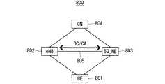
図8は、UEがLTEおよび5Gの両方のRATの基地局に接続する場合の通信システム800の構成の一例を示すブロック図である。通信システム800は、UE801、LTE用の基地局であるeNB802、5G用の基地局である5G_NB803、およびコアネットワーク(Core Network;略称:CN)804を備えて構成される。eNB802および5G_NB803間は、X2リンクによって接続される。ここでは、LTEおよび5Gの両方のRATでの接続を仮定して説明するが、他のRATの任意の組合せでもよい。 FIG. 8 is a block diagram showing an example of the configuration of the
eNB802と5G_NB803とが連携を行い、UE801に対して、LTEおよび5Gの両方のRATによる同時接続を提供する。X2リンク805の性能に応じて、デュアルコネクティビティ(dual connectivity;略称:DC)およびキャリアアグリゲーション(carrier aggregation;略称:CA)のいずれかに、接続形態を切り替える。 The
ここでは、UE801が5G_NB803と接続している状態で、5G_NB803が主体となって、5G_NB803およびeNB802のマルチコネクティビティの制御を行う場合を仮定して説明する。これと逆、すなわち、UE801がeNB802と接続している状態で、eNB802が主体となって、5G_NB803およびeNB802のマルチコネクティビティの制御を行ってもよい。 Here, it is assumed that the
デュアルコネクティビティと、キャリアアグリゲーションとを比較すると、キャリアアグリゲーションの方が密な連携を行う。密な連携を実現するためには、バックホールは、遅延が比較的短いことが要求される。バックホールにおける遅延が十分に短い場合は、キャリアアグリゲーションによる接続とし、バックホールにおける遅延が十分に短くない場合は、デュアルコネクティビティによる接続とするのが望ましい。 Comparing dual connectivity and carrier aggregation, carrier aggregation works more closely. Backhaul is required to have a relatively short delay in order to achieve close coordination. If the delay in the backhaul is sufficiently short, it is desirable to use carrier aggregation, and if the delay in the backhaul is not sufficiently short, it is desirable to use dual connectivity.
接続形態を選択する方法について説明する。デュアルコネクティビティおよびキャリアアグリゲーションの2種の接続形態からいずれかを選択する方法として、X2リンクの遅延を測定して、その測定結果と予め定める遅延用閾値とを比較していずれを選択するかを決定する方法がある。具体的には、X2リンクの遅延の測定結果の値が遅延用閾値未満であるか否かを判断する。X2リンクの遅延の測定結果の値が遅延用閾値未満であると判断された場合に、接続形態としてキャリアアグリゲーションを選択する。前記測定結果の値が遅延用閾値以上であると判断された場合に、接続形態としてデュアルコネクティビティを選択する。 The method of selecting the connection form will be described. As a method of selecting one from two types of connection forms, dual connectivity and carrier aggregation, the delay of the X2 link is measured, and the measurement result is compared with a predetermined delay threshold value to determine which one to select. There is a way to do it. Specifically, it is determined whether or not the value of the measurement result of the delay of the X2 link is less than the delay threshold value. When it is determined that the value of the measurement result of the delay of the X2 link is less than the delay threshold value, carrier aggregation is selected as the connection form. When it is determined that the value of the measurement result is equal to or greater than the delay threshold value, dual connectivity is selected as the connection form.
遅延用閾値は、キャリアアグリゲーションに必要とされる遅延性能の限界値を意味し、X2リンクにおいてキャリアアグリゲーションの接続処理を行うにあたって許容可能な遅延時間の上限値である。遅延用閾値は、例えば、通信システムにおいて、予め、X2リンクの遅延時間を変えて、各遅延時間についてキャリアアグリゲーションの接続処理を行うことが可能か否かを評価して、その評価結果に基づいて決定される。遅延用閾値は、運用開始時に固定の値として通信システムが保持しておくこととする。 The delay threshold value means a limit value of delay performance required for carrier aggregation, and is an upper limit value of an allowable delay time when performing carrier aggregation connection processing in the X2 link. The delay threshold is determined based on, for example, evaluating in advance whether or not it is possible to change the delay time of the X2 link and perform carrier aggregation connection processing for each delay time in the communication system, and based on the evaluation result. It is determined. The delay threshold is held by the communication system as a fixed value at the start of operation.
X2リンクの遅延を測定する方法について説明する。5G_NBが、X2リンク上で、遅延測定用メッセージとして要求(Request)メッセージをeNB宛てに送信する。 A method of measuring the delay of the X2 link will be described. 5G_NB sends a request message to the eNB as a delay measurement message on the X2 link.
eNBは、要求(Request)メッセージを受信すると、直ちに応答(Response)メッセージを5G_NB宛てに送信する。 Upon receiving the Request message, the eNB immediately sends a Response message to 5G_NB.
5G_NBは、応答(Response)メッセージを受信すると、遅延測定用メッセージの往復時間から、X2リンクの遅延を判断する。 Upon receiving the response message, the 5G_NB determines the delay of the X2 link from the round-trip time of the delay measurement message.
X2リンクの遅延は、遅延測定用メッセージの往復を1回のみ実行して、そのときの測定結果のみから判断すると、誤差および突発的な外乱の影響を大きく受けるおそれがある。したがって、前述の影響を平滑化するために、遅延測定用メッセージの往復は、1回に限らず複数回実行して、複数回の遅延測定用メッセージの往復時間の平均値から、X2リンクの遅延を判断してもよい。 The delay of the X2 link may be greatly affected by errors and sudden disturbances when the delay measurement message is reciprocated only once and judged only from the measurement results at that time. Therefore, in order to smooth out the above-mentioned influence, the round trip of the delay measurement message is executed not only once but multiple times, and the delay of the X2 link is calculated from the average value of the round trip times of the multiple delay measurement messages. May be judged.
上記方法では、5G_NBが遅延測定用メッセージの往復時間を測定しているが、5G_NBからの要求によってeNBが測定して、5G_NBに測定結果を報告するようにしてもよい。また、5G_NBによる測定結果と、eNBによる測定結果との両方の結果を用いて、両方の結果のうちの大きい方の値を選択するか、または両方の結果の平均値を最終的な測定結果として採用するようにしてもよい。 In the above method, 5G_NB measures the round-trip time of the delay measurement message, but the eNB may measure the round-trip time according to the request from 5G_NB and report the measurement result to 5G_NB. Also, using both the measurement result by 5G_NB and the measurement result by eNB, the larger value of both results is selected, or the average value of both results is used as the final measurement result. It may be adopted.
X2リンクの遅延を測定する方法としては、上記の方法に限らず、他の公知の測定方法を適用してもよい。 The method for measuring the delay of the X2 link is not limited to the above method, and other known measuring methods may be applied.
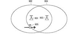
上記接続形態の選択を実行するタイミングについて説明する。図9は、本発明の実施の形態1の通信システムにおけるセルの配置の一例を示す図である。まず、図9のように、5G_NB901のカバレッジ902と、eNB903のカバレッジ904とが重複しており、5G_NB901と接続状態にあるUE905が移動してeNB903のカバレッジ904内に入った場合を想定して説明する。 The timing for executing the selection of the connection form will be described. FIG. 9 is a diagram showing an example of cell arrangement in the communication system according to the first embodiment of the present invention. First, as shown in FIG. 9, it is assumed that the
図10は、本発明の実施の形態1の通信システムにおけるマルチコネクティビティに関する処理のシーケンスの一例を示す図である。 FIG. 10 is a diagram showing an example of a sequence of processing related to multi-connectivity in the communication system according to the first embodiment of the present invention.
ステップST1001において、UEは、5G_NBに、メジャメント報告(Measurement Report)を通知する。5G_NBは、UEから通知されたメジャメント報告を受信する。 In step ST1001, the UE notifies 5G_NB of the Measurement Report. The 5G_NB receives the measurement report notified by the UE.
続いて、ステップST1002において、5G_NBは、受信したメジャメント報告の結果を用いて、メジャメント報告を通知したUEに対して、5G_NBとeNBとによるマルチコネクティビティを開始するか否かを決定する。図10に示す例では、ステップST1002において、5G_NBは、前記UEに対してマルチコネクティビティを開始することを決定する。 Subsequently, in step ST1002, the 5G_NB uses the result of the received measurement report to determine whether or not to start the multi-connectivity by the 5G_NB and the eNB for the UE that has notified the measurement report. In the example shown in FIG. 10, in step ST1002, 5G_NB determines to initiate multi-connectivity to the UE.
続いて、ステップST1003において、5G_NBは、自装置およびeNB間、すなわち5G_NBおよびeNB間のX2リンクの遅延を測定する。X2リンクの遅延の測定が完了すると、ステップST1004に移行する。 Subsequently, in step ST1003, 5G_NB measures the delay of the X2 link between its own device and the eNB, that is, between the 5G_NB and the eNB. When the measurement of the delay of the X2 link is completed, the process proceeds to step ST1004.
ステップST1004において、5G_NBは、X2リンクの遅延の測定結果の値と、予め定める遅延用閾値とを比較して、接続形態を決定する。具体的には、5G_NBは、接続形態として、デュアルコネクティビティおよびキャリアアグリゲーションのいずれを適用するかを決定する。 In step ST1004, 5G_NB compares the value of the measurement result of the delay of the X2 link with the predetermined delay threshold value to determine the connection form. Specifically, 5G_NB determines whether dual connectivity or carrier aggregation is applied as the connection form.
さらに具体的に述べると、5G_NBは、ステップST1003におけるX2リンクの遅延の測定結果の値が、予め定める遅延用閾値未満であるか否かを判断する。5G_NBは、前記遅延の測定結果の値が、予め定める遅延用閾値未満であると判断した場合は、接続形態を、キャリアアグリゲーションに決定する。5G_NBは、前記遅延の測定結果の値が、予め定める遅延用閾値以上であると判断した場合は、接続形態を、デュアルコネクティビティに決定する。 More specifically, 5G_NB determines whether or not the value of the measurement result of the delay of the X2 link in step ST1003 is less than the predetermined delay threshold value. When 5G_NB determines that the value of the measurement result of the delay is less than the predetermined delay threshold value, the connection form is determined to be carrier aggregation. When 5G_NB determines that the value of the measurement result of the delay is equal to or higher than a predetermined delay threshold value, the connection form is determined to be dual connectivity.
ステップST1005において、5G_NBは、ステップST1004で決定した接続形態に応じて、UE、5G_NB、eNBおよびコアネットワークの間での接続シーケンスを行う。具体的には、5G_NBは、DCまたはCAの接続シーケンスを行う。 In step ST1005, 5G_NB performs a connection sequence between the UE, 5G_NB, eNB and the core network according to the connection form determined in step ST1004. Specifically, 5G_NB performs a DC or CA connection sequence.
図11は、本発明の実施の形態1の通信システムにおけるデュアルコネクティビティに関する処理のシーケンスの他の例を示す図である。 FIG. 11 is a diagram showing another example of a sequence of processing related to dual connectivity in the communication system according to the first embodiment of the present invention.
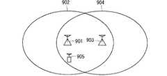
図11のように、5G_NB901のカバレッジ902内かつeNB903のカバレッジ904内の場所にあるUE905が起動して、最初に5G_NB901と接続し、その後にeNB903とも接続を行う場合を想定して説明する。 As shown in FIG. 11, it is assumed that the
図12は、図11の場合における実施の形態1の通信システムにおけるマルチコネクティビティに関する処理のシーケンスの一例を示す図である。図12に示すシーケンスは、図10に示すシーケンスと同一のステップを含んでいるので、同一のステップについては同一のステップ番号を付して、共通する説明を省略する。 FIG. 12 is a diagram showing an example of a sequence of processing related to multi-connectivity in the communication system of the first embodiment in the case of FIG. Since the sequence shown in FIG. 12 includes the same steps as the sequence shown in FIG. 10, the same steps are given the same step numbers, and a common description will be omitted.
ステップST1201において、UEは、UE、5G_NBおよびコアネットワーク間でのアタッチ(Attach)シーケンスを行う。 In step ST1201, the UE performs an Attach sequence between the UE, 5G_NB and the core network.
アタッチシーケンスが完了して、UEが5G_NBに接続された状態となった後、ステップST1001において、UEは、5G_NBに、メジャメント報告(Measurement Report)を通知する。5G_NBは、UEから通知されたメジャメント報告を受信することによって、UEがeNBのカバレッジ内に存在していることを知る。 After the attachment sequence is completed and the UE is connected to the 5G_NB, in step ST1001, the UE notifies the 5G_NB of the Measurement Report. The 5G_NB knows that the UE is within the coverage of the eNB by receiving the measurement report notified by the UE.
ステップST1001の処理が終了した後は、図10に示すシーケンスと同様にして、ステップST1002〜ステップST1005の処理が行われる。 After the processing of step ST1001 is completed, the processing of steps ST1002 to ST1005 is performed in the same manner as in the sequence shown in FIG.
以上のように本実施の形態によれば、UEと、eNBおよび5G_NBとは、異なる複数の接続形態、具体的にはデュアルコネクティビティおよびキャリアアグリゲーションのいずれかによって接続可能である。いずれの接続形態を選択するかは、少なくとも、eNBと5G_NBとを接続するリンク、本実施の形態ではX2リンクの遅延の測定結果に基づいて決定される。これによって、UEと、eNBおよび5G_NBとの接続形態を、異なる複数の接続形態の中から適切に選択することができる。 As described above, according to the present embodiment, the UE and the eNB and 5G_NB can be connected by a plurality of different connection forms, specifically, dual connectivity and carrier aggregation. Which connection form is selected is determined at least based on the measurement result of the delay of the link connecting the eNB and the 5G_NB, or the X2 link in the present embodiment. Thereby, the connection form between the UE and the eNB and 5G_NB can be appropriately selected from a plurality of different connection forms.
また以上のように本実施の形態では、UEが接続される複数の基地局装置は、無線アクセス技術(RAT)が異なる複数の基地局装置、具体的にはLTEによる基地局装置であるeNBと、5Gによる基地局装置である5G_NBとを含む。このような基地局装置に本実施の形態を適用することによって、前述のように、UEと、eNBおよび5G_NBとの接続形態を、異なる複数の接続形態の中から適切に選択することができる通信システムを実現することができる。 Further, as described above, in the present embodiment, the plurality of base station devices to which the UE is connected are a plurality of base station devices having different wireless access technologies (RAT), specifically, eNB which is a base station device by LTE. Includes 5G_NB, which is a 5G base station device. By applying the present embodiment to such a base station apparatus, as described above, the connection form between the UE and the eNB and 5G_NB can be appropriately selected from a plurality of different connection forms. The system can be realized.
実施の形態2.
実施の形態1では、X2リンクの遅延性能に応じて、マルチコネクティビティの接続形態の選択を行うことを想定している。本実施の形態では、その選択を行う基準として、X2リンクの遅延だけでなく、X2リンクのスループットを加える。すなわち、本実施の形態では、X2リンクの遅延とX2リンクのスループットとに応じて、マルチコネクティビティの接続形態を選択する。
In the first embodiment, it is assumed that the multi-connectivity connection form is selected according to the delay performance of the X2 link. In the present embodiment, not only the delay of the X2 link but also the throughput of the X2 link is added as a criterion for making the selection. That is, in the present embodiment, the multi-connectivity connection form is selected according to the delay of the X2 link and the throughput of the X2 link.
本実施の形態における、X2リンクの遅延とX2リンクのスループットとに応じて、マルチコネクティビティの接続形態を選択する方法について説明する。 A method of selecting a multi-connectivity connection form according to the delay of the X2 link and the throughput of the X2 link in the present embodiment will be described.
本実施の形態では、デュアルコネクティビティおよびキャリアアグリゲーションの2種の接続形態のいずれかを選択する方法として、X2リンクの遅延を測定して、その測定結果の値と予め定める遅延用閾値とを比較することに加えて、X2リンクのスループットを測定して、その測定結果の値と予め定めるスループット用閾値とを比較する。 In the present embodiment, as a method of selecting one of the two types of connection forms, dual connectivity and carrier aggregation, the delay of the X2 link is measured, and the value of the measurement result is compared with the predetermined delay threshold value. In addition, the throughput of the X2 link is measured, and the value of the measurement result is compared with the predetermined throughput threshold value.
具体的には、X2リンクの遅延の測定結果の値が遅延用閾値未満であるか否かを判断するとともに、X2リンクのスループットの測定結果の値がスループット用閾値を以上であるか否かを判断する。 Specifically, it is determined whether or not the value of the measurement result of the delay of the X2 link is less than the threshold value for delay, and whether or not the value of the measurement result of the throughput of the X2 link is equal to or more than the threshold value for throughput. to decide.
X2リンクの遅延の測定結果の値が遅延用閾値未満であり、かつX2リンクのスループットの測定結果の値がスループット用閾値以上であると判断された場合には、接続形態として、キャリアアグリゲーションを選択する。 If it is determined that the value of the measurement result of the delay of the X2 link is less than the threshold value for delay and the value of the measurement result of the throughput of the X2 link is equal to or more than the threshold value for throughput, carrier aggregation is selected as the connection form. To do.
X2リンクの遅延の測定結果の値が遅延用閾値未満であるという条件、およびX2リンクのスループットの測定結果の値がスループット用閾値以上であるという条件のうち、少なくとも一方の条件を満たさないと判断された場合には、接続形態として、デュアルコネクティビティを選択する。 It is determined that at least one of the condition that the value of the measurement result of the delay of the X2 link is less than the threshold value for delay and the condition that the value of the measurement result of the throughput of the X2 link is equal to or more than the threshold value for throughput is not satisfied. If so, select dual connectivity as the connection form.
スループット用閾値は、キャリアアグリゲーションに必要とされるスループット性能の限界値を意味する。スループット性能の限界値は、X2リンクにおいて、キャリアアグリゲーションの接続処理を行うにあたって許容可能なスループットの下限値である。スループット用閾値は、例えば、通信システムにおいて、予め、スループットの値を変えて、各スループットの値についてキャリアアグリゲーションが可能か否かを評価して、その評価結果に基づいて決定される。スループット用閾値は、運用開始時に固定の値として通信システムが保持しておくこととする。 The throughput threshold means the limit value of the throughput performance required for carrier aggregation. The limit value of the throughput performance is the lower limit value of the throughput that can be tolerated in performing the carrier aggregation connection processing in the X2 link. For example, in a communication system, the throughput threshold is determined in advance by changing the throughput value, evaluating whether or not carrier aggregation is possible for each throughput value, and based on the evaluation result. The throughput threshold is held by the communication system as a fixed value at the start of operation.
次に、スループットを測定する方法について説明する。5G_NBが、X2リンク上で、スループット情報の要求(Request)メッセージをeNB宛てに送信する。 Next, a method of measuring the throughput will be described. 5G_NB sends a request message for throughput information to the eNB on the X2 link.
要求メッセージを受信したeNBは、自装置の現在のトラフィック流量の測定を行う。続いて、eNBは、自装置の回線の最大スループットのケーパビリティ(capability)と現在のトラフィック流量との差分を、現在のスループットのケーパビリティ情報として導出する。eNBは、導出したケーパビリティ情報を含む応答(Response)メッセージを、5G_NB宛てに送信する。 Upon receiving the request message, the eNB measures the current traffic flow rate of its own device. Subsequently, the eNB derives the difference between the maximum throughput capability of the line of its own device and the current traffic flow rate as the capability information of the current throughput. The eNB sends a response message including the derived capability information to 5G_NB.
5G_NBは、応答メッセージを受信すると、eNBと同様に、自装置の現在のトラフィック流量の測定を行い、現在のスループットのケーパビリティ情報を導出する。そして、5G_NBは、受信した応答メッセージに含まれるeNBの現在のスループットのケーパビリティ情報と、導出した5G_NBの現在のスループットのケーパビリティ情報とから、X2リンクのスループットを判断する。 When the 5G_NB receives the response message, it measures the current traffic flow rate of its own device in the same manner as the eNB, and derives the capability information of the current throughput. Then, 5G_NB determines the throughput of the X2 link from the capability information of the current throughput of the eNB included in the received response message and the capability information of the current throughput of the derived 5G_NB.
本実施の形態では、5G_NBは、5G_NBのスループットのケーパビリティ情報で示される差分の値と、eNBのスループットのケーパビリティ情報で示される差分の値とのうち、小さい方の値をX2リンクのスループットとして採用する。あるいは、5G_NBは、両方の差分の値の平均値をX2リンクのスループットとして採用してもよい。 In the present embodiment, for 5G_NB, the smaller value of the difference value indicated by the 5G_NB throughput capability information and the eNB throughput capability information is the throughput of the X2 link. Adopt as. Alternatively, 5G_NB may adopt the average value of the values of both differences as the throughput of the X2 link.
5G_NBおよびeNBの双方における現在のトラフィック流量の測定は、1回の実行のみで測定結果を判断すると、誤差および突発的な外乱の影響を大きく受けてしまう。したがって、前述の影響を平滑化するために、1回に限らず複数回測定を実行して、複数回の測定値の平均値から、現在のトラフィック流量を判断してもよい。 The current traffic flow measurement in both 5G_NB and eNB is greatly affected by errors and sudden disturbances when the measurement result is judged by only one execution. Therefore, in order to smooth the above-mentioned influence, the measurement may be executed not only once but also a plurality of times, and the current traffic flow rate may be determined from the average value of the measured values.
スループットを測定する方法としては、上記の方法に限らず、他の公知の測定方法を適用してもよい。 The method for measuring the throughput is not limited to the above method, and other known measurement methods may be applied.
次に、上記接続形態の選択を実行するタイミングについて説明する。まず、前述の図9のように、5G_NB901のカバレッジ902と、eNB903のカバレッジ904とが重複しており、5G_NB901と接続状態にあるUE905が移動してeNB903のカバレッジ904内に入った場合を想定して説明する。 Next, the timing for executing the selection of the connection form will be described. First, as shown in FIG. 9, it is assumed that the
図13は、本発明の実施の形態2の通信システムにおけるマルチコネクティビティに関する処理のシーケンスの一例を示す図である。図13に示すシーケンスは、図10に示すシーケンスと同一のステップを含んでいるので、同一のステップについては同一のステップ番号を付して、共通する説明を省略する。 FIG. 13 is a diagram showing an example of a sequence of processing related to multi-connectivity in the communication system according to the second embodiment of the present invention. Since the sequence shown in FIG. 13 includes the same steps as the sequence shown in FIG. 10, the same steps are given the same step numbers, and a common description will be omitted.
本実施の形態では、図10に示すシーケンスと同様にしてステップST1001〜ステップST1003の処理を行った後、ステップST1301に移行する。 In the present embodiment, the processes of steps ST1001 to ST1003 are performed in the same manner as in the sequence shown in FIG. 10, and then the process proceeds to step ST1301.
ステップST1301において、5G_NBは、5G_NBおよびeNB間のX2リンクのスループットを測定する。本実施の形態では、ステップST1003の処理の後にステップST1301の処理を行っているが、ステップST1003の処理とステップST1301の処理との前後関係は問わず、両処理を連続せずに独立に実行してもよい。 In step ST1301, 5G_NB measures the throughput of the X2 link between 5G_NB and eNB. In the present embodiment, the process of step ST1301 is performed after the process of step ST1003, but both processes are executed independently without being continuous regardless of the context of the process of step ST1003 and the process of step ST1301. You may.
ステップST1003におけるX2リンクの遅延の測定と、ステップST1301におけるX2リンクのスループットの測定との両方が完了すると、ステップST1302に移行する。 When both the measurement of the delay of the X2 link in step ST1003 and the measurement of the throughput of the X2 link in step ST1301 are completed, the process proceeds to step ST1302.
ステップST1302において、5G_NBは、X2リンクの遅延の測定結果の値と予め定める遅延用閾値とを比較するとともに、X2リンクのスループットの測定結果の値と予め定めるスループット用閾値とを比較して、接続形態を決定する。具体的には、5G_NBは、接続形態として、デュアルコネクティビティおよびキャリアアグリゲーションのどちらを適用するかを決定する。 In step ST1302, 5G_NB compares the value of the measurement result of the delay of the X2 link with the predetermined delay threshold value, and compares the value of the measurement result of the throughput of the X2 link with the predetermined throughput threshold value to connect. Determine the morphology. Specifically, 5G_NB determines whether to apply dual connectivity or carrier aggregation as the connection form.
さらに具体的に述べると、5G_NBは、ステップST1003におけるX2リンクの遅延の測定結果の値が、予め定める遅延用閾値未満であるか否かを判断するとともに、ステップST1301におけるX2リンクのスループットの測定結果の値が、予め定めるスループット用閾値以上であるか否かを判断する。 More specifically, 5G_NB determines whether or not the value of the delay measurement result of the X2 link in step ST1003 is less than the predetermined delay threshold value, and the measurement result of the throughput of the X2 link in step ST1301. It is determined whether or not the value of is equal to or greater than the predetermined throughput threshold value.
5G_NBは、前記遅延の測定結果の値が遅延用閾値未満であり、かつ前記スループットの測定結果の値がスループット用閾値以上であると判断した場合には、接続形態を、キャリアアグリゲーションに決定する。 When 5G_NB determines that the value of the measurement result of the delay is less than the threshold value for delay and the value of the measurement result of the throughput is equal to or more than the threshold value for throughput, the connection form is determined to be carrier aggregation.
5G_NBは、前記遅延の測定結果の値が遅延用閾値未満であるという条件、および前記スループットの測定結果の値がスループット用閾値以上であるという条件のうち、少なくとも一方の条件を満たさない場合には、接続形態を、デュアルコネクティビティに決定する。 5G_NB does not satisfy at least one of the conditions that the value of the measurement result of the delay is less than the threshold value for delay and the condition that the value of the measurement result of the throughput is equal to or more than the threshold value for throughput. , Determine the connection form to dual connectivity.
次に、前述の図11のように、5G_NB901のカバレッジ902内かつeNB903のカバレッジ904内の場所にあるUE905が起動して、最初に5G_NB901と接続し、その後にeNB903とも接続を行う場合を想定して説明する。 Next, as shown in FIG. 11, it is assumed that the
図14は、図11の場合における実施の形態2の通信システムにおけるマルチコネクティビティに関する処理のシーケンスの一例を示す図である。図14に示すシーケンスは、図10、図12および図13に示すシーケンスと同一のステップを含んでいるので、同一のステップについては同一のステップ番号を付して、共通する説明を省略する。 FIG. 14 is a diagram showing an example of a sequence of processing related to multi-connectivity in the communication system of the second embodiment in the case of FIG. Since the sequence shown in FIG. 14 includes the same steps as the sequences shown in FIGS. 10, 12, and 13, the same steps are given the same step numbers, and common description will be omitted.
本実施の形態では、図11に示すシーケンスと同様にしてステップST1201の処理が行われた後、前述の図10に示すシーケンスと同様にしてステップST1001およびステップST1003の処理が行われる。 In the present embodiment, after the processing of step ST1201 is performed in the same manner as the sequence shown in FIG. 11, the processing of steps ST1001 and ST1003 is performed in the same manner as the sequence shown in FIG.
5G_NBは、ステップST1003において、5G_NBおよびeNB間のX2リンクの遅延を測定した後、ステップST1301において、前述の図13に示すシーケンスと同様にして、5G_NBおよびeNB間のX2リンクのスループットを測定する。 5G_NB measures the delay of the X2 link between 5G_NB and eNB in step ST1003, and then measures the throughput of the X2 link between 5G_NB and eNB in step ST1301 in the same manner as the sequence shown in FIG. 13 described above.
本実施の形態では、ステップST1003の処理の後にステップST1301の処理を行っているが、ステップST1003の処理とステップST1301の処理との前後関係は問わず、両処理を連続せずに独立に実行してもよい。 In the present embodiment, the process of step ST1301 is performed after the process of step ST1003, but both processes are executed independently without being continuous regardless of the context of the process of step ST1003 and the process of step ST1301. You may.
ステップST1003におけるX2リンクの遅延の測定と、ステップST1301におけるX2リンクのスループットの測定との両方が完了すると、ステップST1302に移行する。 When both the measurement of the delay of the X2 link in step ST1003 and the measurement of the throughput of the X2 link in step ST1301 are completed, the process proceeds to step ST1302.
ステップST1302において、5G_NBは、前述の図13に示すシーケンスと同様にして、X2リンクの遅延の測定結果の値と予め定める遅延用閾値とを比較するとともに、X2リンクのスループットの測定結果の値と予め定めるスループット用閾値とを比較して、接続形態を決定する。具体的には、5G_NBは、接続形態として、デュアルコネクティビティおよびキャリアアグリゲーションのどちらを適用するかを決定する。 In step ST1302, 5G_NB compares the value of the measurement result of the delay of the X2 link with the predetermined delay threshold value and the value of the measurement result of the throughput of the X2 link in the same manner as in the sequence shown in FIG. The connection form is determined by comparing with a predetermined throughput threshold value. Specifically, 5G_NB determines whether to apply dual connectivity or carrier aggregation as the connection form.
以上のように本実施の形態によれば、いずれの接続形態を選択するかは、eNBと5G_NBとを接続するリンクの遅延の測定結果と、リンクのスループットの測定結果とに基づいて決定される。本実施の形態では、X2リンクの遅延の測定結果と、X2リンクのスループットの測定結果とに基づいて、いずれの接続形態を選択するかが決定される。これによって、UEと、eNBおよび5G_NBとの接続形態を、より適切に選択することができる。 As described above, according to the present embodiment, which connection mode is selected is determined based on the measurement result of the delay of the link connecting the eNB and the 5G_NB and the measurement result of the throughput of the link. .. In the present embodiment, which connection mode is selected is determined based on the measurement result of the delay of the X2 link and the measurement result of the throughput of the X2 link. Thereby, the connection form between the UE and the eNB and 5G_NB can be selected more appropriately.
実施の形態3.
本発明の実施の形態3における通信システムは、前述の実施の形態1における通信システムと構成が類似しており、実施の形態1と異なる構成について説明し、実施の形態1と同様の構成については説明を省略する。Embodiment 3.
The communication system according to the third embodiment of the present invention has a configuration similar to that of the above-mentioned communication system according to the first embodiment, and a configuration different from the first embodiment will be described. The explanation is omitted.
実施の形態1では、eNBと5G_NBとがX2リンク上で連携して、マルチコネクティビティを行うことを想定している。しかし、基地局同士の連携は、低いレイヤの通信によって行われる方が、高いレイヤの通信によって行われるよりも好ましい。 In the first embodiment, it is assumed that the eNB and the 5G_NB cooperate on the X2 link to perform multi-connectivity. However, cooperation between base stations is preferably performed by low-layer communication rather than high-layer communication.
したがって、本実施の形態では、低いレイヤの通信によって基地局同士の連携を行う。これによって、処理遅延を少なくし、かつ連携のためのメッセージのオーバーヘッドを少なくすることができる。 Therefore, in the present embodiment, the base stations are linked by low-layer communication. As a result, the processing delay can be reduced and the message overhead for cooperation can be reduced.
本実施の形態では、前述の図8に示す通信システムの構成において、eNB802と5G_NB803とが、X2リンク805ではなく、PDCPレイヤでリンクしている場合を想定する。PDCPレイヤに代えて、RLCレイヤなどの他のレイヤのリンクでもよい。 In the present embodiment, in the configuration of the communication system shown in FIG. 8 described above, it is assumed that the
接続形態を選択する方法については、該レイヤにおける遅延の測定結果に基づいて接続形態の選択を行う方法とする。ここでの選択を行う基準となる閾値は、該レイヤのリンクにおいて、キャリアアグリゲーションの接続処理を行うにあたって許容可能な遅延時間の上限値である。 As for the method of selecting the connection form, the connection form is selected based on the measurement result of the delay in the layer. The threshold value that serves as a reference for making the selection here is the upper limit of the delay time that can be tolerated in performing the carrier aggregation connection processing in the link of the layer.
遅延を測定する方法については、該レイヤにおけるメッセージによって測定を行う方法とする。 As for the method of measuring the delay, the method of measuring by the message in the layer is used.
前述の各実施の形態およびその変形例は、本発明の例示に過ぎず、本発明の範囲内において、各実施の形態およびその変形例を自由に組合せることができる。また各実施の形態およびその変形例の任意の構成要素を適宜変更または省略することができる。 Each of the above-described embodiments and modifications thereof is merely an example of the present invention, and each embodiment and variations thereof can be freely combined within the scope of the present invention. Further, any component of each embodiment and its modification can be appropriately changed or omitted.
801,905 UE、802,903 eNB、803,901 5G_NB、804 コアネットワーク(CN)、902 5G_NBのカバレッジ、904 eNBのカバレッジ。 801,905 UE, 802,903 eNB, 803,901 5G_NB, 804 Core Network (CN), 902 5G_NB coverage, 904 eNB coverage.
Claims (5)
Translated fromJapanese前記通信端末装置と前記複数の基地局装置とは、異なる複数の接続形態によって接続可能であり、
前記複数の基地局装置のうちで前記通信端末装置からメジャメント報告を受信した基地局装置は、前記複数の接続形態のうち、いずれの接続形態を選択するかを、少なくとも、前記基地局装置同士を接続するリンクの遅延の測定結果に基づいて決定することを特徴とする通信システム。A communication system including a communication terminal device, a plurality of base station devices that are wirelessly connected to the communication terminal device, and a core network that manages communication between the communication terminal device and each of the base station devices. ,
The communication terminal device and the plurality of base station devices can be connected by a plurality of different connection forms.
Said plurality of base stations having received the measurement report from the communication terminal device among the base station apparatus, among the plurality of connection forms,whether to select one of the topology, at least, the base station apparatus to each other communication system anddetermines based on the measurement result of the delay of the link to be connected.
Priority Applications (1)
| Application Number | Priority Date | Filing Date | Title |
|---|---|---|---|
| JP2016192681AJP6769811B2 (en) | 2016-09-30 | 2016-09-30 | Communications system |
Applications Claiming Priority (1)
| Application Number | Priority Date | Filing Date | Title |
|---|---|---|---|
| JP2016192681AJP6769811B2 (en) | 2016-09-30 | 2016-09-30 | Communications system |
Related Child Applications (1)
| Application Number | Title | Priority Date | Filing Date |
|---|---|---|---|
| JP2020159522ADivisionJP2020202596A (en) | 2020-09-24 | 2020-09-24 | Communication system |
Publications (2)
| Publication Number | Publication Date |
|---|---|
| JP2018056865A JP2018056865A (en) | 2018-04-05 |
| JP6769811B2true JP6769811B2 (en) | 2020-10-14 |
Family
ID=61836065
Family Applications (1)
| Application Number | Title | Priority Date | Filing Date |
|---|---|---|---|
| JP2016192681AExpired - Fee RelatedJP6769811B2 (en) | 2016-09-30 | 2016-09-30 | Communications system |
Country Status (1)
| Country | Link |
|---|---|
| JP (1) | JP6769811B2 (en) |
Families Citing this family (7)
| Publication number | Priority date | Publication date | Assignee | Title |
|---|---|---|---|---|
| CN110649949B (en) | 2018-06-27 | 2021-07-09 | 华为技术有限公司 | A communication method and device |
| JPWO2020022389A1 (en)* | 2018-07-27 | 2021-08-02 | 三菱電機株式会社 | Communication systems, base stations and communication terminals |
| CN108649971B (en)* | 2018-08-20 | 2020-07-07 | 维沃移动通信有限公司 | a terminal device |
| CN118338366A (en)* | 2018-11-26 | 2024-07-12 | 三菱电机株式会社 | Communication system and communication terminal device |
| JP7311991B2 (en) | 2019-03-26 | 2023-07-20 | キヤノン株式会社 | COMMUNICATION DEVICE, COMMUNICATION DEVICE CONTROL METHOD, AND PROGRAM |
| JP7340941B2 (en) | 2019-03-26 | 2023-09-08 | キヤノン株式会社 | Communication device, control method, and program |
| WO2025004138A1 (en)* | 2023-06-26 | 2025-01-02 | 日本電信電話株式会社 | Wireless communication system, wireless communication method, wireless communication device, and wireless communication program |
Family Cites Families (2)
| Publication number | Priority date | Publication date | Assignee | Title |
|---|---|---|---|---|
| JP2015126308A (en)* | 2013-12-26 | 2015-07-06 | 株式会社Nttドコモ | User terminal, radio base station, radio communication method, and radio communication system |
| JP6207440B2 (en)* | 2014-03-20 | 2017-10-04 | Kddi株式会社 | Maintenance management apparatus, wireless communication system, usage architecture determination method, and computer program |
- 2016
- 2016-09-30JPJP2016192681Apatent/JP6769811B2/ennot_activeExpired - Fee Related
Also Published As
| Publication number | Publication date |
|---|---|
| JP2018056865A (en) | 2018-04-05 |
Similar Documents
| Publication | Publication Date | Title |
|---|---|---|
| JP7595737B2 (en) | Communication system, terminal device and SgNB | |
| JP7463447B2 (en) | Mobile communication system, base station and mobile terminal | |
| JP2025063260A (en) | Mobile communication system, mobile terminal and base station | |
| JP7321322B2 (en) | mobile terminal equipment | |
| JP6769811B2 (en) | Communications system | |
| WO2018124259A1 (en) | Communication system | |
| WO2017026159A1 (en) | Communication system | |
| JP7254233B2 (en) | Communication system, base station device and communication terminal device | |
| JP7639075B2 (en) | Communication system, base station and communication terminal | |
| WO2018011777A1 (en) | Communication system, base station device, communication terminal device, and communication method | |
| JP2023179745A (en) | Communication systems, user equipment and base stations | |
| EP3606131A1 (en) | Communications system | |
| JPWO2020110825A1 (en) | Communication system and communication terminal equipment | |
| WO2018011776A1 (en) | Communication system, base station device, communication terminal device, and communication method | |
| JP7434628B2 (en) | Communications system | |
| EP4440233A1 (en) | Communication system |
Legal Events
| Date | Code | Title | Description |
|---|---|---|---|
| A621 | Written request for application examination | Free format text:JAPANESE INTERMEDIATE CODE: A621 Effective date:20190910 | |
| A977 | Report on retrieval | Free format text:JAPANESE INTERMEDIATE CODE: A971007 Effective date:20200515 | |
| A131 | Notification of reasons for refusal | Free format text:JAPANESE INTERMEDIATE CODE: A131 Effective date:20200609 | |
| A521 | Request for written amendment filed | Free format text:JAPANESE INTERMEDIATE CODE: A523 Effective date:20200720 | |
| TRDD | Decision of grant or rejection written | ||
| A01 | Written decision to grant a patent or to grant a registration (utility model) | Free format text:JAPANESE INTERMEDIATE CODE: A01 Effective date:20200825 | |
| A61 | First payment of annual fees (during grant procedure) | Free format text:JAPANESE INTERMEDIATE CODE: A61 Effective date:20200924 | |
| R150 | Certificate of patent or registration of utility model | Ref document number:6769811 Country of ref document:JP Free format text:JAPANESE INTERMEDIATE CODE: R150 | |
| R250 | Receipt of annual fees | Free format text:JAPANESE INTERMEDIATE CODE: R250 | |
| LAPS | Cancellation because of no payment of annual fees |