JP6768885B2 - Image forming device and preview display method of image forming device - Google Patents
Image forming device and preview display method of image forming deviceDownload PDFInfo
- Publication number
- JP6768885B2 JP6768885B2JP2019118293AJP2019118293AJP6768885B2JP 6768885 B2JP6768885 B2JP 6768885B2JP 2019118293 AJP2019118293 AJP 2019118293AJP 2019118293 AJP2019118293 AJP 2019118293AJP 6768885 B2JP6768885 B2JP 6768885B2
- Authority
- JP
- Japan
- Prior art keywords
- image
- display
- mode
- displayed
- preview
- Prior art date
- Legal status (The legal status is an assumption and is not a legal conclusion. Google has not performed a legal analysis and makes no representation as to the accuracy of the status listed.)
- Active
Links
Images


Landscapes
- Accessory Devices And Overall Control Thereof (AREA)
- Record Information Processing For Printing (AREA)
- Digital Computer Display Output (AREA)
- Facsimiles In General (AREA)
Description
Translated fromJapanese本発明は、画像形成装置および画像形成装置のプレビュー表示方法に係り、特に、複数の動作モードを備え、原稿画像をプレビュー表示可能な画像表示操作装置を備えた画像形成装置および画像形成装置のプレビュー表示方法に関する。 The present invention relates to an image forming apparatus and a preview display method of the image forming apparatus, and in particular, a preview of the image forming apparatus and the image forming apparatus including an image display operation apparatus having a plurality of operation modes and capable of preview-displaying an original image. Regarding the display method.
近年、画像形成装置において、原稿画像(入力画像)に対する多彩な編集機能の中から、所望する編集機能を選択して出力物を完成させる画像編集機能を搭載した画像形成装置が知られている。特に、プリンタ機能、コピー機能及びFAX機能などの複数の機能(動作モード)を備えた、いわゆるデジタル複合機においては、原稿画像を画像データとして取り扱うこととなるため、多彩な画像の編集が可能なデジタル画像形成装置として実現されている。 In recent years, in an image forming apparatus, an image forming apparatus equipped with an image editing function for selecting a desired editing function from a variety of editing functions for a manuscript image (input image) to complete an output is known. In particular, in a so-called digital multifunction device equipped with a plurality of functions (operation modes) such as a printer function, a copy function, and a fax function, the original image is handled as image data, so that various images can be edited. It is realized as a digital image forming device.
このような画像形成装置では、上述の各種機能を実行する際の設定を行うため、液晶タッチパネルなどの表示操作部が設けられている。近年のデジタル複合機は、複数の機能が存在する上に、設定すべき項目が多くなっているため、わかりやすい設定画面を表示することや、利用者による設定の操作負担を軽減することが求められている。 In such an image forming apparatus, a display operation unit such as a liquid crystal touch panel is provided in order to make settings when executing the above-mentioned various functions. In recent years, digital multifunction devices have multiple functions and many items to be set, so it is required to display an easy-to-understand setting screen and reduce the burden of setting operations by the user. ing.
近年、複数ページの原稿画像をプレビュー表示可能な画像表示操作装置を備えた画像形成装置が知られている。このような画像形成装置によれば、ジョブの実行前に事前に原稿をスキャン(プリスキャン)した処理結果を表示画面上にプレビュー表示することで、出力する前に読取った原稿を確認することができる。 In recent years, an image forming apparatus including an image display operating apparatus capable of preview-displaying a multi-page original image has been known. According to such an image forming apparatus, it is possible to check the scanned document before outputting it by displaying the processing result of scanning (pre-scanning) the document in advance on the display screen before executing the job. it can.
従来、画像形成装置において、表示画面上にプレビュー表示する場合は、画像読込み装置で読込んだ画像データからプレビュー表示する表示画像を生成し、表示画面上に表示する際には、読込んだ画像をそのまま縮小した表示画像を生成してプレビュー表示するようにされている(特許文献1を参照)。 Conventionally, in an image forming apparatus, when a preview is displayed on a display screen, a display image to be previewed is generated from the image data read by the image reading device, and when the display image is displayed on the display screen, the read image is generated. Is made to generate a reduced display image as it is and display it as a preview (see Patent Document 1).
例えば、カラー原稿を読込んだ場合は、カラーのまま縮小した表示画像を生成してプレビュー表示している。 For example, when a color original is read, a reduced display image is generated in color and previewed.
しかしながら、画像形成装置としての複数の動作モードを有するデジタル複合機には、ファクシミリモードやインターネットファクシミリモードを有するものがあるが、それらの動作モードにおいてはモノクロ画像送信が主流になっているのが現状である。 However, some digital multifunction devices having a plurality of operation modes as an image forming apparatus have a facsimile mode and an Internet facsimile mode, and the current situation is that monochrome image transmission is the mainstream in these operation modes. Is.
従って、デジタル複合機におけるファクシミリ送信やインターネットファクシミリ送信モードにおいては、原稿画像の読込み中や読込完了後の仕上り状態(出力される画像の状態)を確認するためのプレビュー表示(仕上りプレビュー表示)を行う際に、読込まれる原稿がカラー原稿の場合、読込んだカラー画像をそのままカラーの表示画像でプレビュー表示されると、実際に送信される画像のイメージがつかみ難くなるという問題が生じる。 Therefore, in the facsimile transmission or the Internet facsimile transmission mode in the digital multifunction device, a preview display (finish preview display) is performed to confirm the finished state (state of the output image) during or after the reading of the original image. At that time, when the read original is a color original, if the read color image is preview-displayed as a color display image as it is, there arises a problem that it becomes difficult to grasp the image of the image actually transmitted.
そのため、実際に送信される画像のイメージを認識するためには、その都度、カラー画像をモノクロ画像の表示に切り替えるなどの煩雑な操作をしなければならないという問題がある。 Therefore, in order to recognize the image of the image actually transmitted, there is a problem that a complicated operation such as switching the color image to the monochrome image display must be performed each time.
本発明は、上記従来の課題に鑑みてなされたものであり、画像形成装置における複数の動作モードにおいて、煩雑な操作を行うことなく、実際に出力する画像のイメージを即座に確認できる画像形成装置および画像形成装置のプレビュー表示方法を提供することを目的とする。 The present invention has been made in view of the above-mentioned conventional problems, and is an image forming apparatus capable of immediately confirming an image of an image actually output without performing complicated operations in a plurality of operation modes of the image forming apparatus. And an object of the present invention is to provide a preview display method of an image forming apparatus.
本発明の画像形成装置は、読み込まれた原稿画像に基づいて表示画像を生成し、生成された表示画像をプレビュー表示する画像形成装置において、複数の動作モードを選択可能に備え、ファクシミリモード又はインターネットファクシミリモードが選択された場合、読み込まれた原稿画像の色調に関わらず、仕上りプレビュー表示をするときには、モノクロ画像を表示する、ことを特徴とする。 The image forming apparatus of the present invention is an image forming apparatus that generates a display image based on a read original image and preview-displays the generated display image, and is provided with a plurality of operation modes that can be selected from the facsimile mode or the Internet. When the facsimile mode is selected, a monochrome image is displayed when the finish preview is displayed regardless of the color tone of the read original image.
本発明のプレビュー表示方法は、読み込まれた原稿画像に基づいて表示画像を生成し、生成された表示画像をプレビュー表示する画像形成装置のプレビュー表示方法において、複数の動作モードを選択可能に備え、ファクシミリモード又はインターネットファクシミリモードがプレビュー表示する動作モードとして選択された場合、読み込まれた原稿画像の色調に関わらず、仕上りプレビュー表示をするときには、モノクロ画像を表示する、ことを特徴とする。 The preview display method of the present invention is provided with a plurality of operation modes that can be selected in the preview display method of the image forming apparatus that generates a display image based on the read original image and preview-displays the generated display image. When the facsimile mode or the Internet facsimile mode is selected as the operation mode for preview display, a monochrome image is displayed when the finished preview display is performed regardless of the color tone of the read original image.
本発明の画像形成装置によれば、入力された画像データに基づいて表示画像を生成し、生成された表示画像をプレビュー表示する画像形成装置において、複数の動作モードを選択可能に備え、選択された動作モードがコピーモードもしくはE-mail送信モードの場合は、読み込み中のプレビュー表示として、画像データの色調に対応した色調の表示画像を表示し、仕上りプレビュー表示として、機能設定に応じた色調の表示画像を表示することで、選択された動作モードによって、読み込み中のプレビュー表示および仕上りプレビュー表示を画像の色調を変えて表示することで、原稿のプレビュー表示と比較して、実際に実行される出力画像の出力状態を確認することができる。 According to the image forming apparatus of the present invention, in an image forming apparatus that generates a display image based on input image data and displays a preview of the generated display image, a plurality of operation modes can be selected and selected. When the operation mode is copy mode or E-mail transmission mode, the display image of the color tone corresponding to the color tone of the image data is displayed as the preview display during reading, and the color tone according to the function setting is displayed as the finish preview display. By displaying the displayed image, the preview display being read and the finished preview display are displayed in different color tones of the image according to the selected operation mode, and are actually executed in comparison with the preview display of the original. You can check the output status of the output image.
また、本発明の画像形成装置のプレビュー表示方法によれば、入力された画像データに基づいて表示画像を生成し、生成された表示画像をプレビュー表示する画像形成装置のプレビュー表示方法において、複数の動作モードからプレビュー表示する動作モードを選択し、選択された動作モードがコピーモードもしくはE-mail送信モードの場合は、読み込み中のプレビュー表示として、画像データの色調に対応した色調の表示画像を表示し、仕上りプレビュー表示として、機能設定に応じた色調の表示画像を表示することで、選択された動作モードによって、読み込み中のプレビュー表示および仕上りプレビュー表示する画像の色調を変えて仕上げプレビュー表示することで、原稿のプレビュー表示と比較して、実際に実行される出力画像の出力状態を確認することができる。 Further, according to the preview display method of the image forming apparatus of the present invention, there are a plurality of preview display methods of the image forming apparatus that generate a display image based on the input image data and preview-display the generated display image. Select the operation mode to be previewed from the operation mode, and if the selected operation mode is copy mode or E-mail transmission mode, display the display image of the color tone corresponding to the color tone of the image data as the preview display during reading. Then, as the finish preview display, by displaying the display image of the color tone according to the function setting, the color tone of the preview display being loaded and the image to be displayed in the finish preview can be changed according to the selected operation mode to display the finish preview. With, it is possible to confirm the output state of the output image actually executed by comparing with the preview display of the original.
以下、本発明の実施形態について図面を参照して説明する。
図1は発明を実施する形態の一例であって、本発明の実施形態に係る画像形成装置の全体の構成を示す説明図、図2は前記画像形成装置の内部構成を簡略化して示す説明図、図3は前記画像形成装置のハードウェア構成を示す機能ブロック図、図4は前記画像形成装置のタッチパネルディスプレイのプレビュー表示領域を示す説明図、図5は前記タッチパネルディスプレイに表示される画面例を示す説明図、図6は前記タッチパネルディスプレイに表示されるプレビュー領域を変更した状態を示す説明図である。Hereinafter, embodiments of the present invention will be described with reference to the drawings.
FIG. 1 is an example of an embodiment of the present invention, and FIG. 2 is an explanatory diagram showing an overall configuration of an image forming apparatus according to an embodiment of the present invention, and FIG. 2 is an explanatory diagram showing a simplified internal configuration of the image forming apparatus. FIG. 3 is a functional block diagram showing a hardware configuration of the image forming apparatus, FIG. 4 is an explanatory diagram showing a preview display area of the touch panel display of the image forming apparatus, and FIG. 5 is a screen example displayed on the touch panel display. The explanatory view and FIG. 6 are explanatory views showing a state in which the preview area displayed on the touch panel display is changed.
本発明の実施形態は、図1に示すように、コピーモード、ファクシミリモード(FAXモード)等の複数の動作モードを備え、画像データを入力する原稿読取部(入力手段)102と、原稿読取部102から入力される画像データを蓄積する蓄積手段105(図9を参照)と、画像データに基づいて画像出力を行う画像出力手段(出力手段)107と、原稿読取部102により入力された画像データに基づいて記録媒体上に画像を形成する画像形成部104とを備えるとともに、蓄積手段105に蓄積された画像データに基づいて表示画像を生成する表示画像生成手段137(図9を参照)と、画像データに基づいてプレビュー画像を表示する表示パネル(表示手段)132と、表示画像生成手段137により生成された表示画像を表示パネル132にプレビュー表示する操作ユニット側制御部(表示制御手段)131(図9を参照)とを具備する操作ユニット(画像表示操作装置)120とを備える画像形成装置100において、操作ユニット側制御部131及び表示画像生成手段137の構成をとして、本発明に係る画像形成装置の構成を採用したものである。 As shown in FIG. 1, an embodiment of the present invention includes a document reading unit (input means) 102 and a
表示パネル132に表示される複数原稿画像は、画像形成装置100の原稿読取部などから取り込まれた原稿画像の形態をプレビュー表示(仕上りプレビュー表示)するものであり、且つ、画像形成部から記録用紙上に形成される画像の出力形態を仕上りプレビュー画像として表示するものである。 The plurality of original images displayed on the
本実施形態に係る画像形成装置100は、複数の動作モードを備え、その動作モードが切り換えられて表示機器の画面が切り換えられた場合において、ユーザが画面構成を覚えていなくても、ユーザが求める情報をユーザが容易に取得することができるように、情報を表示する表示機器を備えた装置であればよい。 The
尚、本実施形態に係る画像形成装置100は、ジェスチャー操作方法とジェスチャー操作によらないタッチ操作方法とにより操作が可能なタッチパネルディスプレイ(操作画面)を備えるとするが、タッチ操作のみが可能なタッチパネルディスプレイを備える装置であってもよく、さらには、操作が不可能な表示のみ可能な表示パネル及び操作用のボタンを備える装置であってもよい。 It is assumed that the
この画像形成装置100は、電子写真方式により記録用紙に画像を形成する。
また、画像形成装置100は、動作モードとして、コピーモード、ファクシミリモード(FAXモード)、ドキュメントファイリングモード(スキャンした画像を画像形成装置内部の記憶装置に記憶するモード)及びメールモード(スキャンした画像を電子メールに添付する形式で送信するモード)を備える。尚、この画像形成装置100は、さらにネットワークプリンタモードを備えていても構わない。The
Further, the
また、本発明はこれに限定されず、動作モード毎に画面が切り換わる画像形成装置であれば構わない。また、印刷方式は電子写真方式に限定されない。 Further, the present invention is not limited to this, and any image forming apparatus that switches the screen for each operation mode may be used. Further, the printing method is not limited to the electrophotographic method.
まず、本発明の実施形態に係る画像形成装置100について説明する。
本実施形態に係る画像形成装置100は、図1に示すように、原稿読取部102、画像形成部104、給紙部106、排紙処理装置108、及び、操作ユニット120を備える。
操作ユニット120は、タッチパネルディスプレイ130と表示操作部140とで構成される。タッチパネルディスプレイ130は、液晶パネル等で構成された表示パネル132と、表示パネル132に重ねて配置されたユーザの指で押圧された位置を検出するタッチパネル(タッチ操作認識手段)134とで構成される。表示操作部140は、表示灯142と、電源キー144と、省エネルギーキー(以下「省エネキー」と記載)146と、動作モードを選択するホーム画面ヘタッチパネルディスプレイ130の表示画面を戻すためのホームキー148とで構成される。First, the
As shown in FIG. 1, the
The
このように画像形成装置100は、主たる操作デバイスとしてタッチパネルディスプレイ130を備えるとともに、ハードウェアキー及び表示灯により構成される表示操作部140を備える。表示操作部140のキー(電源キー144、省エネキー146、ホームキー148)は、タッチパネルディスプレイ130により構成されるソフトウェアボタンと対比して、ハードウェアボタンとして構成される点が特徴である。 As described above, the
尚、画像形成装置100は、このような構成の表示操作部140を備えるものに限定されず、タッチパネルディスプレイ130のみを備えるものであってもよい。タッチパネルディスプレイ130に表示されたホーム画面においてユーザが動作モードを選択すると、選択された動作モードにおける初期画面に切り換わるものであれば構わない。このような画像形成装置100の動作モードについて説明する。 The
(コピーモード)
以下において、画像形成装置100のコピーモードでの動作について説明する。
このコピーモードにおいては、主として、原稿読取部(以下、「スキャナ部」と称する。)102及び画像形成部104が動作する。(Copy mode)
The operation of the
In this copy mode, the document reading unit (hereinafter, referred to as “scanner unit”) 102 and the
画像形成装置100においては、原稿載置台に置かれた原稿が原稿読取部102により画像データとして読取られ、読取られた画像データが図3に示すマイクロコンピュータ等から構成されるCPU300に入力され、ここで画像データに各種の画像処理が施され、この画像データが画像形成部104へと出力される。 In the
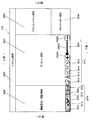
画像形成部104は、図2に示すように、画像データによって示される原稿の画像を記録媒体(多くの場合、記録用紙)に印刷するものであって、感光体ドラム222、帯電装置224、レーザスキャンユニット(以下、「LSU」と称する。)226、現像装置228、転写装置230、クリーニング装置232、定着装置234、及び図示しない除電装置等を備えている。 As shown in FIG. 2, the
画像形成部104には、主搬送路236及び反転搬送路238が設けられており、給紙部106から給紙されてきた記録用紙が主搬送路236に沿って搬送される。給紙部106は、用紙カセット240に収納された記録用紙、または手差トレイ242に載置された記録用紙を1枚ずつ引出して記録用紙を画像形成部104の主搬送路236へと送り出す。 The
画像形成部104の主搬送路236に沿って記録用紙が搬送されている途中で、記録用紙が感光体ドラム222と転写装置230との間を通過し、さらに定着装置234を通過して、記録用紙に対する印刷が行われる。 While the recording paper is being conveyed along the
感光体ドラム222は、一方向に回転し、その表面は、クリーニング装置232と除電装置によりクリーニングされた後、帯電装置224により均一に帯電される。 The
LSU226は、印刷対象の画像データに基づいてレーザ光を変調し、このレーザ光によって感光体ドラム222の表面を主走査方向に繰返し走査して、静電潜像を感光体ドラム222の表面に形成する。 The LSU226 modulates the laser beam based on the image data to be printed, and the laser beam repeatedly scans the surface of the
現像装置228は、トナーを感光体ドラム222の表面に供給して静電潜像を現像し、トナー像を感光体ドラム222の表面に形成する。 The developing
転写装置230は、当該転写装置230と感光体ドラム222との間を通過していく記録用紙に感光体ドラム222の表面のトナー像を転写する。 The
定着装置234は、記録用紙を加熱するための加熱ローラ248と、記録用紙を加圧するための加圧ローラ250とを含む。記録用紙は、加熱ローラ248によって加熱され、かつ、加圧ローラ250によって加圧されることによって、記録用紙上に転写されたトナー像が記録用紙に定着される。この定着装置234へ供給される電力によりヒータを温めて加熱ローラ248の温度が定着に適した温度になるように制御されている。尚、省エネモードに移行すると、例えば、このヒータへ供給される電力が停止されたり削減されたりする。 The fixing
主搬送路236と反転搬送路238との接続位置には、分岐爪244が配設されている。記録用紙の片面のみに印刷が行われる場合は、分岐爪244が位置決めされ、この分岐爪244により定着装置234からの記録用紙が排紙トレイ246または排紙処理装置108の方へと導かれる。 A
記録用紙の両面に印刷が行われる場合は、分岐爪244が所定方向に回動されて記録用紙が一旦排紙トレイ246側へ導かれた後、スイッチバック搬送されて反転搬送路238の方へと導かれる。記録用紙は、反転搬送路238を通過して、その表裏を反転されて主搬送路236へと再び搬送され、主搬送路236の再度の搬送途中で、その裏面への印刷が行われて排紙トレイ246または排紙処理装置108の方へと導かれる。 When printing is performed on both sides of the recording paper, the
上述のようにして印刷された記録用紙は、排紙トレイ246または排紙処理装置108の方へと導かれて排紙トレイ246に排出され、または排紙処理装置108の各排紙トレイ110の何れかに排出される。 The recording paper printed as described above is guided toward the
排紙処理装置108では、複数の記録用紙を各排紙トレイ110に仕分けして排出する処理、各記録用紙にパンチングする処理、及び各記録用紙にステープルする処理を施す。例えば、複数部の印刷物を作成する場合は、各排紙トレイ110に印刷物の一部ずつが割り当てられるように、各記録用紙を各排紙トレイ110に仕分けして排出し、排紙トレイ110毎に、排紙トレイ110上の各記録用紙に対しパンチングユニット111によるパンチング処理またはステープルユニット112によるステープル処理を施して印刷物を作成する。 The
(ファクシミリモード)
以下において、ファクシミリモードでの動作について説明する。
このファクシミリモードにおいては、図3に示すように、主として、送信動作は原稿読取部(スキャナ部)102及びFAX通信部160が動作することにより、受信動作はFAX通信部160及び画像形成部104が動作する。(Facsimile mode)
The operation in the facsimile mode will be described below.
In this facsimile mode, as shown in FIG. 3, the transmission operation is mainly performed by the document reading unit (scanner unit) 102 and the
(送信動作)
画像形成装置100においては、ファクシミリモードを指定して、原稿載置台に置かれた原稿が原稿読取部102により画像データとして読取られ、読取られた画像データが図3に示すマイクロコンピュータ等から構成されるCPU300に入力され、ここで画像データに各種の画像処理が施され、この画像データがFAX通信部(図3のFAX通信部160)へと出力される。(Transmission operation)
In the
図3に示すように、送信側の画像形成装置100のFAX通信部160は、指定された送信側の回線を指定された送信先に接続して、画像データをファクシミリ通信規格に合致した通信データへ変換して、受信側のファクシミリ装置(例えばファクシミリ機能を備えた画像形成装置100)へ送信する。 As shown in FIG. 3, the
(通信動作)
回線が接続されると、受信側の画像形成装置100のFAX通信部160は、送信側の画像形成装置100のFAX通信部160からの通信要求信号を検出して、応答信号を送信する。その後、例えば、FAX通信部160は、送信側及び受信側で互いに実装されている能力情報の受渡しを行ない、利用可能な最大能力での通信速度及び画像データの符号化・符号訂正方式などを決定してモデムの通信方式を設定する。この通信方式にあわせた画像信号静式を用いて、送信側の画像形成装置100のFAX通信部160から受信側の画像形成装置100のFAX通信部160ヘデータを送信する。送信が終了すると回線が切断される。(Communication operation)
When the line is connected, the
(受信動作)
受信側の画像形成装置100のFAX通信部160は、受信したデータを画像データに変換して、画像形成部104へ送る。尚、受信したデータを画像データへ変換するのは画像形成部104であっても構わない。画像形成部104は、上述したコピーモードにおける動作と同じように、受信したデータから変換された画像データによって示される原稿の画像を記録用紙に印刷する。(Reception operation)
The
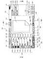
次に、画像形成装置100の制御ブロック構成について図面を参照して説明する。
図3に示すように、画像形成装置100は、さらに、コピーモード、ファクシミリモードとして装置が搭載する機能の設定が可能な操作ユニット120と、プログラム等を記憶するためのROM306と、通電が遮断された場合であってもプログラム及びデータ等を記憶可能な不揮発性記憶領域であるハードディスク302と、プログラムを実行する際の記憶領域を提供するためのRAM(Random Access Memory)308とを含む。Next, the control block configuration of the
As shown in FIG. 3, the
画像形成装置100は、さらに、原稿読取部102、画像形成部104、FAX通信部160、操作ユニット120、ROM306、ハードディスク302、及びRAM308に接続されるパス310と、パス310に接続された、画像形成装置としての一般的機能を実現するためのCPU300とを含む。 The
ハードディスク302には、この画像形成装置100でスキャンした原稿の画像データのファイルが記憶される。また、ハードディスク302には、各動作モードの初期画面データが記憶されている。(ハードディスク302でなくてもROM306に記憶させておくことも可能) The
ROM306には、画像形成装置100の動作を制御するのに必要なプログラム及びデータ等が記憶されている。このROM306にプログラムとともに記憶するデータとして、各動作モードの初期画面データを記憶するようにしても構わない。CPU300は、ROM306に格納されているプログラム及びデータに従って画像形成装置100の制御を行うとともに画像形成装置100の各機能に関する制御を実行する。 The
図3に示すように、この画像形成装置100のFAX通信部160には、画像データの送受信用に公衆回線が接続され、ネットワークインターフェイス304には、ネットワーク回線が接続されている。このネットワーク回線には、この画像形成装置100をネットワーク対応のプリンタとして使用するコンピュータ等が接続されたり、インターネットを介して指定されたURL(Uniform Resource Locator)により特定されるコンピュータ等が接続されたりする。このようにインターネットに接続されると、画像形成装置100は、インターネットを介して、必要な情報を取得することができる。 As shown in FIG. 3, a public line is connected to the
RAM308は、CPU300による演算及び処理の結果を一時的に記憶するワーキングメモリとしての機能と、画像データを記憶するフレームメモリとしての機能とを提供する。 The
原稿読取部102、画像形成部104、操作ユニット120を構成するタッチパネルディスプレイ130及び表示操作部140、ならびにROM306、ハードディスク302、及びRAM308に対する制御は、CPU300が所定のプログラムを実行することにより行われる。尚、操作ユニット120は、入出力インターフェイスを介してCPU300と通信する。 Control of the
操作ユニット120は、ユーザが目視しやすいように傾斜して設けられた板状のパネルで構成される。操作ユニット120の表面には、その左側の領域にタッチパネルディスプレイ130が、右側の領域に表示操作部140(表示灯142ならびにハードウェアボタンである電源キー144、省エネキー146及びホームキー148)が、備えられている。タッチパネルディスプレイ130及び表示操作部140は、操作ユニット120が全体として一体となるように構成されている。 The
上述したように、このタッチパネルディスプレイ130は、表示パネル132と、表示パネル132に重ねて配置されたタッチパネル134とで構成される。 As described above, the
このタッチパネルディスプレイ130においては、表示パネル132に、この画像形成装置100における動作モードを選択するホーム画面、この画像形成装置100の現在の状態、宛先指定状況、ジョブの処理状況等が表示される。表示パネル132のプレビュー表示領域上にはソフトウェアボタンである選択ボタンが表示され、この選択ボタンの表示されている領域を指で押すと、タッチパネル134がその押された位置を検出する。プログラム上で、選択ボタンの表示位置とタッチパネル134が押された位置とを照合することにより、画像形成装置100の動作モード選択、機能設定及び動作指示等が行われる。この画像形成装置100はこのようなタッチ操作(ユーザによる押圧位置に基づくコマンド入力操作)に加えて、上述したジェスチャー操作(ユーザによる操作軌跡に基づくコマンド入力操作)にも対応している。 In the
また、表示操作部140の表示灯142は、例えばLED(Light Emitting Diode)で構成され、CPU300により点灯/消灯(/点滅)が制御される。主電源スイッチとは別に設けられた電源キー144をユーザが押下すると、この画像形成装置100が待機モード(例えば主電源がオンの状態でFAX受信動作のみ可能)から通常モードへ移行して、この画像形成装置100の全ての動作モードが使用できるようになる。この状態に連動して表示灯142が点灯する。さらに、ユーザが操作しない時間が予め定められた時間を経過したり、省エネキー146をユーザが押下したりすると、この画像形成装置100が通常モードから省エネモードへ移行して、この画像形成装置100の一部の動作モードしか使用できないようになる。この状態に連動して表示灯142が点滅する。さらに、この省エネモードのときに、省エネキー146をユーザが押下すると、この画像形成装置100が省エネモードから通常モードへ移行する。ホームキー148は、タッチパネルディスプレイ130の表示を初期状態(ホーム画面)へ戻すためのハードウェアキーである。尚、電源キー144、省エネキー146及びホームキー148を押下したときの処理はこれらに限定されるものではない。 Further, the
尚、表示操作部140のハードウェアボタン(電源キー144、省エネキー146及びホームキー148)には、CPU300により点灯/消灯(/点滅)が制御されるキーランプを埋め込むようにしても構わない。例えば、このキーランプは、円型のキーの5周囲をリング状に光らせたり、キーの中央部を光らせたりする。操作デバイスとしてハードウェアボタンを使用することが許可されているタイミングで(ハードウェアボタンを使用すると処理が実行されるタイミングで)、このキーランプが点灯する。 A key lamp whose lighting / extinguishing (/ blinking) is controlled by the
本実施形態に係る画像形成装置100においては、上述した2つの動作モード(コピーモード、ファクシミリモード)を備える。タッチパネルディスプレイ130には、それぞれの動作モードにおける機能設定用のソフトウェアボタンと、必要に応じて、画像形成イメージであるプレビューまたは宛先設定用のボタン等が表示される。 The
動作モードが違う場合には、タッチパネルディスプレイ130は、異なる画面が表示される。このような場合であっても、ユーザが要求する情報を容易に見つけることのできるように、タッチパネルディスプレイ130は複数の領域に分割されて(かつその領域の大きさを可変として)、各領域に情報を表示するという本発明の本質的部分を備える。特にこの画像形成装置100においては、主たる表示操作デバイスとして設けられたタッチパネルディスプレイ130のホーム画面において動作モードを選択すると、各動作モードの初期画面が表示される。 When the operation modes are different, the
この初期画面において、(1)基本レイアウトが5つの領域(「システム領域」、「機能選択領域」、「プレビュー領域」、「アクションパネル領域」、「タスクトリガー領域」)に分割されて適切に配置されているので、左上から右下へユーザが操作することにより(このような大型のタッチパネルディスプレイ130を備えない従来機と同じようなユーザの視点の動線及び指先の動線が実現されるために)容易に設定が可能で、(2)異なる動作モードであっても5つの領域のそれぞれに表示される概念は同じものであって、動作モードが異なってもユーザが混乱することなく操作が可能である。
以下に、このような基本レイアウトの構成について説明する。In this initial screen, (1) the basic layout is divided into five areas ("system area", "function selection area", "preview area", "action panel area", "task trigger area") and arranged appropriately. Therefore, when the user operates from the upper left to the lower right (because the flow line of the user's viewpoint and the flow line of the fingertip similar to those of the conventional machine without such a large
The configuration of such a basic layout will be described below.
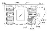
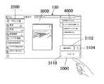
まず、画像形成装置100のタッチパネルディスプレイ130における基本レイアウトについて図面を参照して説明する。
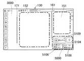
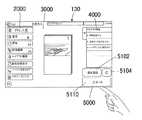
タッチパネルディスプレイ130の基本レイアウトは、図4に示すように、横長のタッチパネルディスプレイ130において(例えば、横1024ピクセル×縦600ピクセル)、最上部に配置されたシステム領域1000、画面中央部に配置されたプレビュー領域(プレビュー表示領域)3000、プレビュー領域3000の左側に配置された機能設定/確認領域2000(以下、機能選択領域2000と記載する)、プレビュー領域3000の右上部に配置されたアクションパネル領域4000、及び、プレビュー領域3000の右下部に配置されたタスクトリガー領域(操作キー表示領域)5000で構成される。First, the basic layout of the
As shown in FIG. 4, the basic layout of the
尚、タッチパネルディスプレイ130における領域の数は5つに限定されるものではなく、左右の並びもこれに限定されず、例えば、ユーザの利き手に応じて領域の左右の配置を逆にしても構わない。また、システム領域1000の位置は最下部であっても構わない。また、状態もしくは設定によっては表示されなくても構わない。 The number of areas on the
システム領域1000には、この画像形成装置100の現時点での状態が表示され、操作中の動作モードのタイトル、画像形成装置100の状況・状態が表示される。例えば、システム領域1000には、動作モード名、割り込みキー、ログインユーザ名、処理中のジョブ状況、内蔵メモリ使用状態、時刻等が表示される。 The current state of the
機能選択領域2000には、各機能の設定、表示の切り換え、設定の確認のためにユーザにより操作される機能選択メニュー(アイコン、ボタン等)が、アイコンモード、レギュラーモード及びエキスプレスモードで表示態様を変更して、表示される。アイコンモードにおいては、プレビュー領域3000が最も広くなるように機能選択領域2000には機能設定用のアイコンのみが表示される。エキスプレスモードにおいては、プレビュー領域3000が最も狭くなっても機能選択領域2000には機能を一度に設定できる画面が大きく表示される。レギュラーモードにおいては、プレビュー領域3000の大きさはアイコンモードとエキスプレスモードとの中間の大きさであって、機能選択領域2000には機能設定のアイコンとともに機能名称がテキスト表示される。 In the
これらのアイコンモード、レギュラーモード及びエキスプレスモードの切り換えはユーザの操作に基づく。すなわち、プレビュー領域3000の大きさが、ユーザの操作に応じて変更して表示される。このように、アイコンは、小さい領域でユーザへの情報を伝達することができるので、全ての機能に対して準備しておいて、プレビュー領域3000が大きく表示できることが好ましい。 Switching between these icon mode, regular mode and express mode is based on the user's operation. That is, the size of the
この機能選択領域2000には、その下部に機能選択領域2000の表示スタイルを変更する変更ボタン群2010を備える。変更ボタン群2010には、アイコンモードで機能選択領域2000を表示するアイコンモード移行ボタン2012、「お気に入り」登録した機能を表示させるお気に入りボタン2014、設定が変更された機能を表示させるチェックボタン2016、選択されている動作モードにおいて設定可能な全ての機能の一覧を表示するリストボタン2018、レギュラーモードで機能選択領域2000を表示するレギュラーモード移行ボタン2020、及び、エキスプレスモードで機能選択領域2000を表示するエキスプレスモード移行ボタン2022が配置されている。 The
尚、機能選択領域2000に表示される情報が多い場合には、この機能選択領域2000において上下方向に移動表示可能に情報が表示される。この場合において、この変更ボタン群2010は移動表示されないで、機能選択領域2000の最下部に常に表示される。 When a large amount of information is displayed in the
プレビュー領域3000には、原稿の出力(仕上り)イメージが表示される。ダミーデータまたはスキャンデータを用いてイメージ表示し、ユーザが仕上りを変更する毎にプレビュー領域3000に表示されているイメージが変更される。このプレビュー領域3000においては、スキャン前のバーチヤルモードでのダミーイメージでの仕上り表示、スキャン後のスキャンインモードでの実イメージでの仕上り表示の2つのモードを有し、さらにバーチヤルモードには、原稿セット前及び原稿セット後の2種類がある。 The output (finished) image of the original is displayed in the
このプレビュー領域3000には、その下部にプレビュー領域3000の表示スタイルを変更するプレビュー変更ボタン群3010を備える。プレビュー変更ボタン群3010には、プレビューを左に90度回転させる左回転ボタン3016、プレビューを右に90度回転させる右回転ボタン3018、ズームバー3020が配置されている。これら以外にも、例えばカラー変更ボタン3012及びプレビュー操作ボタン3014が配置されている。 The
ここで、左回転ボタン3016を1回タッチ操作するとプレビューが左に90度回転されて、2回タッチ操作するとプレビューが左に180度回転される(上下反転)。また、プレビュー領域に表示された仕上り原稿イメージをジェスチャー操作しても(指先で原稿イメージを反時計回転方向に180度回転させても)、プレビューが左に180度回転されて上下反転される。 Here, if the
右回転ボタン3018を1回タッチ操作するとプレビューが右に90度回転されて、2回タッチ操作するとプレビューが右に180度回転される(上下反転)。また、プレビュー領域に表示された仕上り原稿イメージをジェスチャー操作しても(指先で原稿イメージを時計回転方向に180度回転させても)、プレビューが右に180度回転されて上下反転される。 Touching the right-
ズームバー3020のプラスボタン3020Aをタッチ操作したり、バ−3020Cをプラスボタン3020A側へジェスチャー操作(ドラッグまたはスライド)したりすると、プレビューが拡大して表示される。また、プレビュー領域に表示された仕上り原稿イメージをジェスチャー操作しても(指先で原稿イメージをピンチアウト/ピンチオープンさせても)、プレビューが拡大して表示される。 When the
ズームバー3020のマイナスボタン3020Bをタッチ操作したり、バ−3020Cをマイナスボタン3020B側ヘジェスチャー操作(ドラッグまたはスライド)したりすると、プレビューが縮小して表示される。また、プレビュー領域に表示された仕上り原稿イメージをジェスチャー操作しても(指先で原稿イメージをピンチイン/ピンチクローズさせても)、プレビューが縮小して表示される。 When the
尚、プレビュー領域3000に表示される原稿イメージのページ数が多い場合には、タッチ操作可能な表示ページ選択ボタン(ページ番号入力ボタン、ページ送りボタン、ページ戻しボタン、単ページ表示ボタン、複数ページ表示ボタン等)を表示するようにしても構わない。尚、原稿イメージをスライドタッチ(フリック操作)してもプレビューされる原稿のページ送り、ページ戻しを行うことができる。また、プレビュー領域3000に表示される原稿イメージが大きい場合には、タッチ操作またはジェスチャー操作可能なスクロールバーを表示するようにしても構わない。 If the number of pages of the original image displayed in the
アクションパネル領域4000には、操作についての補助・助言・提案についての情報が表示される。このアクションパネル領域4000には、例えば、あるユーザが特定の機能を選択すると、その機能に関連する機能を表示したり、目的指向でその機能についての他の機能を表示したり、このユーザまたはこのユーザが所属するグループのユーザが過去に組み合わせて選択した機能を「おすすめ機能」として表示したりする。 In the
タスクトリガー領域5000には、その動作モードにおける全ての設定が完了して、この画像形成装置100を実際に動作させるためにユーザにより操作されるトリガー一項目が表示される。例えば、処理を開始させるためのスタートボタン(ソフトウェアボタン)である。尚、印字を伴う動作モード(ファクス送信以外)において、消耗品切れについての情報も、タスクの実行不可に関連するので、この「タスクトリガー領域」に表示される。 In the
この場合において、スタートボタンが押下できる状態の場合にのみ、スタートボタンを表示することも好ましい。スタートボタンが押下できる状態とは、印字を伴う動作モードの場合には、全ての設定が終了してかつ消耗品(記録用紙およびトナー)切れでない状態であって、印字を伴わない動作モードであるファクシミリモード(送信)の場合には、宛先を含む全ての送信パラメータの設定が終了した状態である。 In this case, it is also preferable to display the start button only when the start button can be pressed. The state in which the start button can be pressed is a state in which all settings are completed and consumables (recording paper and toner) are not exhausted in the case of an operation mode involving printing, and the operation mode does not involve printing. In the case of facsimile mode (transmission), all transmission parameters including the destination have been set.
これらの5領域は、動作モードが変更されても(どの動作モードの初期画面においても、その配置された位置は変更されない。また、機能選択領域2000(およびプレビュー領域3000)におけるアイコンモード/レギュラーモード/エキスプレスモードの切り換え表示のように、領域はタッチパネルディスプレイ130の画面横方向(長手方向)に伸縮してサイズが変化する。 Even if the operation mode is changed (the position of the five areas is not changed in the initial screen of any operation mode), the icon mode / regular mode in the function selection area 2000 (and the preview area 3000) is not changed. As in the / express mode switching display, the area expands and contracts in the horizontal direction (longitudinal direction) of the screen of the
このような5領域の配置は、従来機におけるユーザインターフェイスをも考慮しつつ、ユーザの視点の動線及び操作の動線に着目して配置されている。このような配置により、タッチパネルディスプレイ130において、左上から右下へユーザの視線が動いて、左上から右下へユーザの操作(利き手の指先)が動く。 The arrangement of such five regions pays attention to the flow line of the user's viewpoint and the flow line of the operation while considering the user interface in the conventional machine. With such an arrangement, in the
尚、ある動作モードから他の動作モードへ遷移するためには、ホームキー148を押下して、ホーム画面において他の動作モードを選択する。このように、ホーム画面を経由して、動作モードが切り換えられる。 In order to transition from a certain operation mode to another operation mode, the
(コピーモードの初期画面表示動作)
コピーモードが選択されると、ハードディスク302等から読出したコピー初期画面データを用いてタッチパネルディスプレイ130にコピーモードの初期画面が表示される。
このとき、例えば、タッチパネルディスプレイ130には、図5に示すように、コピーモード初期画面7100が表示される。コピーモード初期画面7100は、上述したレイアウト構成の5領域に分割されて情報が表示される。(Initial screen display operation in copy mode)
When the copy mode is selected, the initial screen of the copy mode is displayed on the
At this time, for example, the
コピーモード初期画面7100のシステム領域1000には、図5に示すように、選択されている動作モード(ここではコピーモード)を示すエリア1102、選択された動作モードに付随するサブ情報を表示するエリア1104、ログインユーザ名を表示するエリア1106、ログアウトボタン(ソフトウェアボタン)が表示されるエリア1108、現在実行中のジョブ状況を表示するエリア1110、ジョブ状況に関係するボタン(ソフトウェアボタン)が表示されるエリア1112、通信状態が表示されるエリア1114、現在時刻が表示されるエリア1116が配置されている。 As shown in FIG. 5, the
エリア1102には、動作モードを示す名称または/及びアイコンが表示される。
このエリア1102をタッチ操作、タップ操作またはダブルタップ操作すると、動作モードを示すメニューがプルダウン表示されて動作モードを切り換えることができるようにすることも好ましい(他の動作モードにおいても同じ)。A name or / and an icon indicating the operation mode are displayed in the
When the
エリア1104には、サブ情報として、割り込みキー(ソフトウェアボタン)が表示される。この割り込みキーをタッチ操作、タップ操作またはダブルタップ操作すると、コピーモードにおいて割り込み処理を実行することができる。 An interrupt key (software button) is displayed as sub-information in the
エリア1112には、現在実行中のジョブ状況がアイコンで表示される。このジョブ状況をタッチ操作、タップ操作またはダブルタップ操作すると、詳細なジョブ状況情報が表示される。さらに、エリア1112には、選択されたジョブを停止させるボタン等を表示することも好ましい。 In the
コピーモード初期画面7100の機能選択領域2000には、コピーモードにおいてユーザが選択できる機能選択メニュー2100及び上述した変更ボタン群2010が表示されている。図5に示す画面では、レギュラーモードで機能選択メニューが表示されている。 In the
図5に示すように、レギュラーモードで表示される機能選択メニューは、アイコン群2100とテキスト群2120とで構成される。この機能選択領域2000に表示される機能選択メニューとして、コピー部数を設定するアイコン2102及び設定された内容を表示するテキス卜2122、カラーモードを設定するアイコン2104及び設定された内容を表示するテキスト2124、コピー濃度を設定するアイコン2106及び設定された内容を表示するテキスト2126、コピー倍率を設定するアイコン2108及び設定された内容を表示するテキスト2128、原稿の種類を設定するアイコン2110及び設定された内容を表示するテキスト2130、用紙の種類を設定するアイコン2112及び設定された内容を表示するテキスト2132、画像を編集するアイコン2114及び設定された内容を表示するテキスト2134、レイアウトを編集するアイコン2116及び設定された内容を表示するテキスト2136が表示されている。 As shown in FIG. 5, the function selection menu displayed in the regular mode is composed of an
尚、上述したように、これらの機能設定メニューにおけるさらなる項目は、変更ボタン群2010の表示位置を固定した状態で、上下方向に移動表示可能に表示することができる。そして、上下方向に隠れて表示されていない項目を含めて機能設定メニューの表示項目を切り換えることは、タッチ操作(スクロール操作)でもジェスチャー操作(上下方向へフリック操作)の何れの操作でも可能である。 As described above, further items in these function setting menus can be displayed so as to be movable in the vertical direction while the display position of the
ここで、画像編集とは、1ページの原稿に対する画像編集であって、さらに下位の階層メニューとして、枠消去、印字メニュー、ウォータマーク、ユーザスタンプ等があり、レイアウト編集とは、複数ページの原稿に対する画像編集であって、さらに下位の階層メニューとして、ページ集約、綴じしろ、ページ移動、センタリング等がある。これらのさらなる下位メニューは、アイコン2102〜アイコン2116またはテキスト2122〜テキス卜2136をタッチ操作、タップ操作またはダブルタップ操作すると、タッチパネルディスプレイ130に表示される。 Here, image editing is image editing for a one-page manuscript, and there are frame erasure, print menu, water mark, user stamp, etc. as lower level menus, and layout editing is a multi-page manuscript. Image editing for, and lower hierarchical menus include page aggregation, binding margin, page movement, centering, and the like. These further submenus are displayed on the
コピーモード初期画面7100のプレビュー領域3000には、原稿の出力(仕上り)イメージ3100及び上述したプレビュー変更ボタン群3010が配置されている。このとき、ダミーデータまたはスキャンデータを用いてイメージ3100が表示され、ユーザが機能選択領域2000の機能設定メニューを変更する毎に、イメージ3100が変更されてプレビュー領域3000に表示される(プレビューの表示が変更)。 In the
コピーモード初期画面7100のアクションパネル領域4000には、コピー操作についての補助・助言・提案についての情報が表示されている。ここでは、図5に示すように、このユーザが選択したコピーモードにおけるおすすめ機能が表示される。このとき、アクションパネル領域4000は、表示されている情報の内容を示すエリア4100、それ自体がソフトウェアボタンとしておすすめ機能をテキスト表示するエリア4102〜エリア4106が配置されている。 In the
エリア4102をタッチ操作、タップ操作またはダブルタップ操作すると、省エネコピーについてのさらに詳細な情報がプルダウン表示される。例えば、このとき、「両面印刷すると用紙を節約できます」というテキストとともに両面コピーの機能設定画面へ遷移するソフトウェアボタンと、「複数の原稿を集約して印刷すると用紙を節約できます」というテキストとともにページ集約の機能設定画面へ遷移するソフトウェアボタンと、「本のように綴じられるように印刷することができます」というテキストとともに中綴じの機能設定画面へ遷移するソフトウェアボタンとが、表示される。 When the
コピーモード初期画面7100のタスクトリガー領域5000には、実行ボタン群5100が表示される。この実行ボタン群5100として、原稿をスキャンして画像データを取得するように画像形成装置100を作動させるスキャンインキー(ソフトウェアボタン)5102、設定した機能をクリアするクリアオールキー(ソフトウェアボタン)5104、原稿をスキャンしてモノクロコピーを実行するように画像形成装置100を作動させるモノクロスタートキー(ソフトウェアボタン)5106、原稿をスキャンしてカラーコピーを実行するように画像形成装置100を作動させる力ラースタートキー(ソフトウェアボタン)5108が配置されている。 The
尚、ファクシミリモードの場合は、モノクロスタートキー5106、力ラースタートキー5108の換わりにスタートキー5110が表示される(図13を参照)。 In the facsimile mode, the
このように、5つの領域に分割して情報が表示されたコピーモード初期画面7100において、ユーザが要求を入力すると、その要求に従ってコピー処理が実行される。 In this way, when the user inputs a request on the copy mode
次に、機能選択領域2000をアイコンモードで表示してプレビュー領域3000を広げた場合の、プレビューページの変更動作について説明する。 Next, the operation of changing the preview page when the
図6に示すように、プレビューのイメージ3118が表示されている場合において、ユーザが、プレビュー表示された画面をユーザが左へフリックすると、入力軌跡が分析される。このとき、このユーザによるジェスチャー操作はページをめくる要求であると分析されて、フリックした方向に応じた表示されていない別のページを含むプレビューイメージが表示される。 As shown in FIG. 6, when the
また、このようにプレビューイメージが表示されるページを移動させるには、ページ送りボタン3118G、ページ早送りボタン3118H、ページ戻しボタン3118E、ページ早戻しボタン3118Dをタッチ操作しでも可能である。さらに、ページ直接指定ボタン3118Fをタッチして直接移動させたいページを入力することにより、プレビューイメージが表示されるページを移動させることも可能である。 Further, in order to move the page on which the preview image is displayed in this way, the page forward button 3118G, the page
このように、機能選択領域2000がアイコンモードで表示されると、プレビュー領域3000が広がり、図6に示すように、ユーザの視認性及びユーザの操作性が高まるように、プレビューイメージを表示することができる。特に、タッチ操作またはジェスチャー操作により、表示させたいプレビューイメージまで移動して、所望のプレビューを表示させることができる。 In this way, when the
尚、図6に示すごみ箱アイコン3118Aは、選択したページをごみ箱アイコン3118Aまでドラッグすることによりそのページを削除することができる。 The
また、1ページ表示アイコン3118Bを押下することにより、例えば3ページ表示していたプレビューが1ページ表示になり(このとき1ページ分を大きく表示)、複数ページ表示アイコン3118Cを押下することにより、例えば、1ページ表示していたプレビューが3ページ表示になる。 Further, by pressing the one-page display icon 3118B, for example, the preview displaying three pages becomes one-page display (at this time, one page is displayed larger), and by pressing the
次に、本実施形態の画像形成装置100の特徴的な構成について図面を参照して説明する。
図7は本実施形態の画像形成装置のタッチパネルディスプレイを構成する表示パネルの表示態様を示す説明図、図8は前記タッチパネルディスプレイのプレビュー表示領域の表示態様の一例を示す説明図である。Next, the characteristic configuration of the
FIG. 7 is an explanatory diagram showing a display mode of a display panel constituting the touch panel display of the image forming apparatus of the present embodiment, and FIG. 8 is an explanatory diagram showing an example of a display mode of a preview display area of the touch panel display.
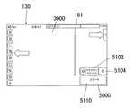
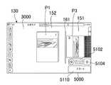
本実施形態の画像形成装置100は、図7に示すように、タッチパネルディスプレイ130において、プレビュー領域3000が画面中央部に配置され、そのプレビュー領域3000の左側に機能選択領域2000が配置される。また、プレビュー領域3000の右上部にアクションパネル領域4000が配置され、そのアクションパネル領域4000の下部にタスクトリガー領域5000が配置される。 In the
タッチパネルディスプレイ130は、図8に示すように、プレビュー領域3000が拡大された状態で、アクションパネル領域4000に相当する位置に第1の表示領域151が形成され、プレビュー領域3000内の略中央部に第1の表示領域151よりも広い範囲で第2の表示領域152が形成されている。 As shown in FIG. 8, in the
第1の表示領域151には、入力された画像データに基づき生成された表示画像が表示される。第2の表示領域152には、第1の表示領域151に表示された表示画像を第1の表示領域151に表示した後に表示される。 A display image generated based on the input image data is displayed in the
第1の表示領域151と第2の表示領域152とは隣接して配置されている。
第1の表示領域151と第2の表示領域152との間には、それらの領域の境界を示す境界ライン161が表示されている。The
A
境界ライン161は、原稿読込時における「画面案内表示」を行うときに、第1の表示領域151に表示される原稿画像が読込まれる動作を行う読取りラインであって、原稿読取部102により原稿が読込まれる状況をタッチパネルディスプレイ130上で簡易的に表現するものである。本実施形態では、境界ライン161は、タッチパネルディスプレイ130の上下方向に直線的な緑色のラインで表示される。 The
さらに、タッチパネルディスプレイ130には、プレビュー領域3000に表示される表示画像を表示パネル132の左側端部に向って移動表示する基準位置となる出力ライン(表示基準部)171が表示されている。 Further, the
出力ライン171は、画像出力時における「画面案内表示」を行うときに、第2の表示領域152に表示された画像が出力される際の表示パネル132上での基準となるラインであって、画像出力手段107(図9を参照)により画像出力される状況をタッチパネルディスプレイ130上で簡易的に表現するものである。本実施形態では、出力ライン171は、タッチパネルディスプレイ130の上下方向に直線的な黄色のラインで表示される。 The
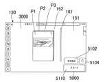
タスクトリガー領域5000は、プレビュー領域3000を拡大して表示されるときには、縮小化されることなく、プレビュー領域3000の右下部で境界ライン161付近に常に表示される。 When the
タスクトリガー領域5000には、実行ボタン群5100が表示される。
実行ボタン群5100として、スキャンインキー5102、クリアオールキー5104、モノクロスタートキー5106、力ラースタートキー5108が配置されている。The
As the
スキャンインキー5102は、図8に示すように、スキャンインの指示により原稿をスキャンして画像データの取得が開始されると、装置の動作を中断する(読込を中止する)中断キー(操作キー)5109に変更されて表示される。 As shown in FIG. 8, the scan-in key 5102 interrupts the operation of the device (stops reading) when the document is scanned and the acquisition of image data is started according to the scan-in instruction (operation key). It is changed to 5109 and displayed.
次に、本実施形態の画像形成装置100における操作ユニット120の特徴的な画面表示に係る電気的構成について図面を参照して説明する。
図9は本実施形態の画像形成装置における操作ユニットの電気的構成を示すブロック図、図10は前記操作ユニットを構成するタッチパネルディスプレイの構成を示すブロック図である。Next, the electrical configuration related to the characteristic screen display of the
FIG. 9 is a block diagram showing an electrical configuration of an operation unit in the image forming apparatus of the present embodiment, and FIG. 10 is a block diagram showing a configuration of a touch panel display constituting the operation unit.
本実施形態に係る操作ユニット120は、図9に示すように、表示パネル132、タッチパネル134に加えて、操作位置検出手段135、画面表示手段136、表示画像生成手段137及び操作ユニット120における処理・動作を制御する操作ユニット側制御部(表示制御手段)131を備えている。 As shown in FIG. 9, the
画像形成装置100は、画像データを入力する原稿読取部102、画像処理手段103、原稿読取部102から入力される画像データを蓄積する蓄積手段105、プリンタや送信部などの画像を出力する画像出力手段107を備えて、主制御部101により動作制御される。 The
操作位置検出手段135は、タッチパネル134上で行われる操作位置を検出する。
画面表示手段136は、表示画像生成手段137により形成された画像を表示パネル132上に表示する。また、画面表示手段136は、画像出力手段107による画像出力(FAX送信)が開始されるときに、表示画像生成手段137により生成された表示画像を表示パネル132に表示する機能を備えている。The operation position detecting means 135 detects an operation position performed on the
The screen display means 136 displays the image formed by the display image generation means 137 on the
表示画像生成手段137は、画像形成装置100本体に入力された画像データに基づき操作ユニット側制御部131からの指示により所定の画像を形成する。そして、表示画像生成手段137は、複数の動作モードの中から選択された動作モードに対応して、蓄積手段105に蓄積された画像データの色調を制御した表示画像を生成する機能(表示画像色調制御機能)を備えている。 The display image generation means 137 forms a predetermined image according to an instruction from the operation unit
具体的には、表示画像生成手段137は、例えば、選択された動作モードがコピーモードの場合は、蓄積手段105に蓄積された画像データがカラーの画像データのときは、蓄積手段105に蓄積された画像データの色調を制御してカラーの表示画像を生成するようにされている。 Specifically, the display image generation means 137 is stored in the storage means 105, for example, when the selected operation mode is the copy mode and the image data stored in the storage means 105 is color image data. The color tone of the image data is controlled to generate a color display image.
一方、選択された動作モードがファクシミリモードの場合は、出力される画像がモノクロ画像となるため、蓄積手段105に蓄積された画像データがカラーの画像データであっても、蓄積手段105に蓄積された画像データの色調を制御してモノクロの表示画像を生成するようにされている。 On the other hand, when the selected operation mode is the facsimile mode, the output image is a monochrome image, so even if the image data stored in the storage means 105 is color image data, it is stored in the storage means 105. The color tone of the image data is controlled to generate a monochrome display image.
操作ユニット側制御部131は、画像形成装置100本体の主制御部101に接続され、タッチパネルディスプレイ130における制御部として機能する。 The operation unit
ここで、操作ユニット側制御部131について詳細に説明する。
操作ユニット側制御部131は、図10に示すように、表示パネル132に複数ページの原稿画像をプレビュー表示するプレビュー表示機能と、プレビュー表示された複数ページの原稿画像を移動表示するスクロール表示機能と、原稿読取部102から入力される画像データの入力状況を表示パネル132上に表示して案内する入力状況案内機能と、画像出力手段107から出力される画像の出力状況を表示パネル132上に表示して案内する出力状況案内機能を備えている。Here, the operation unit
As shown in FIG. 10, the operation unit
また、操作ユニット側制御部131は、表示パネル132上に表示画像を表示する表示画像表示手段1310として、表示画像生成手段137により生成された表示画像を第1の表示領域151に表示する第1の表示領域表示手段1311と、第1の表示領域151に表示された表示画像を第2の表示領域152に向って移動表示させた後に第2の表示領域152に表示する第2の表示領域表示手段1312とを備えている。 Further, the operation unit
さらに、操作ユニット側制御部131は、プレビュー表示機能として、入力された画像を確認するためのプレビュー機能(入力画像プレビュー表示機能)を備えている。
そして、入力画像プレビュー表示時には、蓄積手段105に蓄積された画像データに基づき色調を変更することなく表示画像を生成し、この生成された表示画像をタッチパネルディスプレイ130上の表示パネル132にプレビュー表示するようにされている。Further, the operation unit
Then, at the time of displaying the input image preview, a display image is generated based on the image data stored in the storage means 105 without changing the color tone, and the generated display image is preview-displayed on the
また、操作ユニット側制御部131は、プレビュー表示機能として、複数の動作モードのうちから選択された動作モードに対応した表示画像を表示パネル132にプレビュー表示するようにされている(動作モード対応プレビュー表示機能)。 Further, the operation unit
操作ユニット側制御部131は、複数の動作モードが同時に設定された場合は、複数の動作モードのうちの1つの動作モードを主モードとして設定し、表示画像生成手段137により主モードに対応して蓄積手段105に蓄積された画像データの色調を制御して生成された表示画像をタッチパネルディスプレイ130上の表示パネル132にプレビュー表示するようにされている。 When a plurality of operation modes are set at the same time, the operation unit
操作ユニット120は、コピーモードとファクシミリモードとを含む複数の動作モードを同時に設定可能に構成されている。 The
例えば、主モードとしてコピーモードが設定された場合は、表示画像生成手段137は、蓄積手段105に蓄積された画像データに基づく表示画像をカラー画像として生成し、操作ユニット側制御部131は、表示画像生成手段137により生成されたカラー画像を表示パネル132にプレビュー表示するようにされている。 For example, when the copy mode is set as the main mode, the display image generation means 137 generates a display image based on the image data stored in the storage means 105 as a color image, and the operation unit
また、主モードとしてファクシミリモード(またはインターネットファクシミリモード)が設定された場合は、表示画像生成手段137は、蓄積手段105に蓄積された画像データに基づく表示画像をモノクロ画像として生成し、操作ユニット側制御部131は、表示画像生成手段137に生成されたモノクロ画像を表示パネル132にプレビュー表示するようにされている。 When the facsimile mode (or the Internet facsimile mode) is set as the main mode, the display image generation means 137 generates a display image based on the image data stored in the storage means 105 as a monochrome image, and the operation unit side. The
本実施形態では、原稿読取部102による画像データの入力は、原稿読取部102の最大能力(フルカラー、高解像度)で入力するようにされている。 In the present embodiment, the image data is input by the
ここで、本実施形態の画像形成装置100において、複数の動作モードのうちの2つの動作モードを同時に設定した場合について説明する。
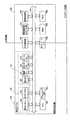
図11は本実施形態の画像形成装置の動作モードにおける表示条件に応じたプレビュー画像を示す表である。Here, in the
FIG. 11 is a table showing preview images according to display conditions in the operation mode of the image forming apparatus of the present embodiment.
画像形成装置100において、動作モードとして、コピーモード、ファクシミリモード、インターネットファクシミリモード、Eメールモード、保存モードが設定可能に構成されている。 The
これらの複数の動作モードのうちの2つの動作モードが選択されて、一方の動作モードを主モードとし、他方の動作モードを副モードとして設定されている。 Two of these plurality of operation modes are selected, and one operation mode is set as the main mode and the other operation mode is set as the sub mode.
具体的には、主モードと副モードとの関係は、図11に示すように、主モードをコピーモード、ファクシミリモード(インターネットファクシミリモード)、Eメールモードとしたときに、副モードはそれぞれ主モードと異なる動作モードに設定されている。 Specifically, as shown in FIG. 11, the relationship between the main mode and the sub mode is as follows. When the main mode is the copy mode, the facsimile mode (Internet facsimile mode), and the e-mail mode, the sub modes are the main modes, respectively. It is set to a different operation mode.
そして、それぞれの動作モードに対応して、表示画像生成手段137により蓄積手段105に蓄積された画像データの色調を制御した表示画像を生成してプレビュー表示するように構成されている。 Then, corresponding to each operation mode, the display image generation means 137 is configured to generate a display image in which the color tone of the image data stored in the storage means 105 is controlled and display the preview.
コピーモードが主モードで設定される場合は、副モードとしてファクシミリモード、インターネットファックスモード、保存モード、Eメールモードが設定され、読込み中のプレビュー表示はカラー画像、仕上りプレビュー表示は機能設定による画像(初期はカラー画像に設定)、原稿プレビュー表示はカラー画像でそれぞれ表示される。 When the copy mode is set in the main mode, the facsimile mode, internet fax mode, save mode, and e-mail mode are set as the sub modes, the preview display during reading is a color image, and the finish preview display is an image according to the function settings ( Initially set to a color image), the original preview display is displayed as a color image.
ファクシミリモード(FAXモード)またはインターネットファクシミリモード(I−FAXモード)が主モードで設定される場合は、副モードとしてコピーモード、保存モード、Eメールモードが設定され、読込み中のプレビュー表示はモノクロ画像、仕上りプレビュー表示はモノクロ画像、原稿プレビュー表示はカラー画像でそれぞれ表示される。 When the facsimile mode (FAX mode) or the Internet facsimile mode (I-FAX mode) is set in the main mode, the copy mode, save mode, and e-mail mode are set as the sub modes, and the preview display during reading is a monochrome image. , The finish preview display is displayed as a monochrome image, and the original preview display is displayed as a color image.
Eメールモードが主モードで設定される場合は、副モードとしてファクシミリモード、インターネットファックスモード、保存モード、コピーモードが設定され、読込み中のプレビュー表示はカラー画像、仕上りプレビュー表示は機能設定による画像(初期はカラー画像に設定)、原稿プレビュー表示はカラー画像でそれぞれ表示される。 When the e-mail mode is set in the main mode, the facsimile mode, internet fax mode, save mode, and copy mode are set as the sub modes, the preview display during reading is a color image, and the finish preview display is an image according to the function settings ( Initially set to a color image), the original preview display is displayed as a color image.
以上のように構成したので、それぞれの動作モードにおいて、設定された主モードに応じてそれぞれのプレビュー表示に対応してカラー画像やモノクロ画像によって表示される。これにより、それぞれの動作モードにおいて最適な表示画像がプレビュー表示されるので、出力される画像を容易に確認できる。 Since it is configured as described above, in each operation mode, a color image or a monochrome image is displayed corresponding to each preview display according to the set main mode. As a result, the optimum display image is preview-displayed in each operation mode, so that the output image can be easily confirmed.
尚、上記例では、動作モードとして主モードと副モードによる複数の動作モードを設定しているが、副モードを設定しなければ、単独の動作モードに対応して蓄積手段105に蓄積された画像データの色調を制御して最適な表示画像を設定するものとして対応できることは言うまでもない。 In the above example, a plurality of operation modes according to the main mode and the sub mode are set as the operation modes, but if the sub mode is not set, the image stored in the storage means 105 corresponding to the single operation mode. Needless to say, it can be used to control the color tone of data and set the optimum display image.
次に、本実施形態の画像形成装置100のタッチパネルディスプレイ130上における原稿読取り時に表示されるプレビュー表示について、フローチャートに沿って説明する。
図12は本実施形態の画像形成装置において原稿読取部による原稿読取状況をタッチパネルディスプレイ上でプレビュー表示を行うときの動作の一例を示すフローチャートである。Next, the preview display displayed when the document is read on the
FIG. 12 is a flowchart showing an example of an operation when previewing the document reading status by the document reading unit on the touch panel display in the image forming apparatus of the present embodiment.
図12に示すように、画像形成装置100において、タッチパネルディスプレイ130上に表示されるスキャンインキー5102がタッチされることにより読取り開始が指示され(ステップS1)、原稿サイズがA4縦またはB5縦であるかが判断される(ステップS2)。 As shown in FIG. 12, in the
ステップS2で原稿サイズがA4縦またはB5縦であると判断された場合、原稿読取部102により原稿画像が読取られて画像データとして蓄積手段105に記憶される(ステップS3)。 When it is determined in step S2 that the original size is A4 vertical or B5 vertical, the original image is read by the
そして、蓄積手段105に記憶された画像データに基づき表示画像生成手段137により縮小されたカラー画像とモノクロ画像の表示画像が生成される(ステップS4)。 Then, based on the image data stored in the storage means 105, the display images of the color image and the monochrome image reduced by the display image generation means 137 are generated (step S4).
そして、出力形態がFAX送信であるか否かが判断され(ステップ5)、ステップS5でFAX送信であると判断された場合は、タッチパネルディスプレイ130上にモノクロ画像がプレビュー表示される(ステップS6)。 Then, it is determined whether or not the output form is fax transmission (step 5), and if it is determined in step S5 that the output mode is fax transmission, a monochrome image is previewed on the touch panel display 130 (step S6). ..
一方、ステップ5でFAX送信ではない判断された場合は、タッチパネルディスプレイ130上にカラー画像がプレビュー表示される(ステップS7)。 On the other hand, if it is determined in
ステップS2に戻って、ステップS2で原稿サイズがA4縦またはB5縦であると判断されなかった場合は、ステップS8に進み、原稿読取部102により原稿画像が読取られて画像データとして蓄積手段105に記憶される。そして、蓄積手段105に記憶された画像データに基づき表示画像生成手段137により縮小されたカラー画像とモノクロ画像の表示画像が生成される(ステップS9)。 Returning to step S2, if it is not determined in step S2 that the document size is A4 portrait or B5 portrait, the process proceeds to step S8, and the document image is read by the
そして、出力形態がFAX送信であるか否かが判断され(ステップ10)、ステップS10でFAX送信であると判断された場合は、タッチパネルディスプレイ130上にモノクロ画像がプレビュー表示される(ステップS11)。 Then, it is determined whether or not the output form is fax transmission (step 10), and if it is determined in step S10 that the output mode is fax transmission, a monochrome image is preview-displayed on the touch panel display 130 (step S11). ..
一方、ステップ5でFAX送信ではない判断された場合は、タッチパネルディスプレイ130上にカラー画像がプレビュー表示される(ステップS12)。 On the other hand, if it is determined in
このようにして、原稿読取りが行われたときには、動作モードに応じて、選択された動作モードがFAX送信の場合には、表示画面にはモノクロ画像がプレビュー表示され、その他の出力態様(例えば、プリンタ出力やカラーコピー)の場合には、表示画面にはカラー画像がプレビュー表示されるので、読取った時点で実際に送信する白黒の画像で即座に確認できる。 In this way, when the document is read, a monochrome image is previewed on the display screen according to the operation mode when the selected operation mode is FAX transmission, and other output modes (for example, for example). In the case of printer output or color copy), a color image is previewed on the display screen, so you can immediately check the black-and-white image that is actually transmitted when it is read.
次に、本実施形態の画像形成装置100のタッチパネルディスプレイ130上における原稿読取り時のプレビュー表示について、具体的に例を挙げて図面を参照して説明する。 Next, a preview display at the time of reading a document on the
(実施例1)
まず、画像形成装置100において、原稿をA4縦送りにセットして原稿読取及び画像出力を行う場合について説明する。
図13〜図29は本実施形態の画像形成装置において原稿をA4縦送りで行う場合の原稿読取時のタッチパネルディスプレイ上に表示されるプレビュー画像の表示状態を示す説明図である。(Example 1)
First, in the
13 to 29 are explanatory views showing a display state of a preview image displayed on the touch panel display at the time of reading the original when the original is fed in A4 vertical feed in the image forming apparatus of the present embodiment.
まず、画像形成装置100において、原稿を読取るときのタッチパネルディスプレイ130に表示される表示画像(読取られた画像)の案内表示について説明する。 First, the guidance display of the display image (read image) displayed on the
画像形成装置100において、原稿は、原稿読取部102にA4縦送りにセットされている。原稿を読取る場合は、タッチパネルディスプレイ130に表示されたホーム画面においてユーザがファクシミリモードを選択して、図13に示すように、スキャンインキー5102をタッチして原稿の読込みを開始する。 In the
スキャンインキー5102により原稿の読取りが指示されると、図14に示すように、タッチパネルディスプレイ130の機能設定領域2000とアクションパネル領域4000の表示情報が左右両サイドに矢印方向にそれぞれ引き込まれて、プレビュー領域3000が拡張され、プレビュー領域3000内に設定される第1の表示領域151と第2の表示領域152との境界を示す境界ライン161が表示される。この境界ライン161は、原稿読取部102により原稿が読込まれる状況をタッチパネルディスプレイ130上で簡易的に表現するものであるため、以下「読取りライン」と称する。 When the scan-in key 5102 instructs to read the original, as shown in FIG. 14, the display information of the
原稿が原稿読取部102に読取られると、読取られた1枚目の原稿の画像データから表示画像生成手段137により縮小された表示画像が生成されて、図15に示すように、読取りライン161の右側の第1の表示領域151に1枚目の画像P1が表示される。このとき、動作モードとしてファクシミリモードが選択されているので、プレビュー表示される画像は全てモノクロ画像で表示される。 When the original is read by the
1枚目の画像P1は、第2の表示領域152に向って、すなわち読取りライン161に向って(右側から左側に向って)徐々に画像が明瞭となるように表示されている。 The first image P1 is displayed toward the
第1の表示領域151に表示された1枚目の画像P1は、図16に示すように、読取りライン161に向って移動して、図17に示すように、読取りライン161を通って読取りライン161の左側の第2の表示領域152に移動して表示される。そして、1枚目の画像P1は、図18に示すように、第2の表示領域152において、時計回り方向に90°回転移動して、図19に示すように、A4縦位置で配置される。 The first image P1 displayed in the
このとき、第1の表示領域151には、原稿読取部102に読取られた2枚目の原稿の画像データから表示画像生成手段137により生成された2枚目の画像P2が縮小されて表示される。 At this time, in the
第1の表示領域151に表示される2枚目の画像P2は、第2の表示領域152に向って、すなわち読取りライン161に向って(右側から左側に向って)徐々に画像が明瞭となるように表示されている。 The second image P2 displayed in the
そして、第1の表示領域151に表示された2枚目の画像P2は、図20に示すように、読取りライン161に向って移動して、読取りライン161を通って読取りライン161の左側の第2の表示領域152に移動して表示される。 Then, as shown in FIG. 20, the second image P2 displayed in the
そして、2枚目の画像P2は、図21に示すように、1枚目の画像P1の背後に重ねて配置され、図22に示すように、時計回り方向に90°回転移動して、図23に示すように、A4縦位置で配置される。このとき、2枚目の画像P2は、表示画面上で存在が確認できるように一部を1枚目の画像P1の下から露出した状態で配置される。 Then, the second image P2 is arranged behind the first image P1 as shown in FIG. 21, and is rotated by 90 ° in the clockwise direction as shown in FIG. As shown in 23, it is arranged in the A4 vertical position. At this time, the second image P2 is arranged in a state where a part of the second image P2 is exposed from below the first image P1 so that its existence can be confirmed on the display screen.
そして、このとき、第1の表示領域151には、原稿読取部102に読取られた3枚目の原稿の画像データから表示画像生成手段137により生成された3枚目の画像P3が縮小されて表示される。 Then, at this time, in the
第1の表示領域151に表示される3枚目の画像P3は、第2の表示領域152に向って、すなわち読取りライン161に向って(右側から左側に向って)徐々に画像が明瞭となるように表示されている。 The third image P3 displayed in the
そして、第1の表示領域151に表示された3枚目の画像P3は、読取りライン161に向って移動して、図24に示すように、読取りライン161を通って読取りライン161の左側の第2の表示領域152に移動して表示される。
このとき、3枚目の画像P3は、図25に示すように、2枚目の画像P2の背後にさらに重ねて配置され、図26に示すように、時計回り方向に90°回転移動して、図27に示すように、A4縦位置で配置される。このとき、3枚目の画像P3は、表示画面上で存在が確認できるように一部を2枚目の画像P2の下から露出した状態で配置される。Then, the third image P3 displayed in the
At this time, the third image P3 is further overlapped behind the second image P2 as shown in FIG. 25, and is rotated by 90 ° in the clockwise direction as shown in FIG. 26. , As shown in FIG. 27, are arranged in the A4 vertical position. At this time, the third image P3 is arranged in a state where a part of the third image P3 is exposed from below the second image P2 so that its existence can be confirmed on the display screen.
以上のように、原稿読取部102により読取られた原稿の表示画像の表示と移動が繰り返されて、図27に示すように、全ての原稿のスキャンインによる事前読込が完了すると、図28,図29に示すように、機能設定領域2000とアクションパネル領域4000の表示がもとの状態に戻されるとともに、読取りライン161が消去される。 As described above, the display and movement of the display image of the document read by the
このようにして、ファクシミリモードにおいて原稿がA4縦送りで読取られる状況をタッチパネルディスプレイ130上で容易に確認することができ、FAX送信される画像がモノクロ画像であることが容易に確認することができる。 In this way, the situation in which the original is read in A4 vertical feed in the facsimile mode can be easily confirmed on the
(実施例2)
次に、画像形成装置100において、原稿をA4横送りにセットして原稿読取及び画像出力を行う場合について説明する。
図30〜図39は本実施形態の画像形成装置において原稿をA4縦送りで行う場合の原稿読取時のタッチパネルディスプレイ上に表示されるプレビュー画像の表示状態を示す説明図である。(Example 2)
Next, in the
30 to 39 are explanatory views showing a display state of a preview image displayed on the touch panel display at the time of reading the original when the original is fed in A4 vertical feed in the image forming apparatus of the present embodiment.
まず、画像形成装置100において、原稿を読取るときのタッチパネルディスプレイ130に表示される表示画像の案内表示について説明する。 First, the guidance display of the display image displayed on the
画像形成装置100において、原稿は、原稿読取部102にA4横送りにセットされている。原稿を読取る場合は、タッチパネルディスプレイ130に表示されたホーム画面においてユーザがファクシミリモードを選択して、図30に示すように、スキャンインキー5102をタッチして原稿の読込みを開始する。 In the
スキャンインキー5102により原稿の読取りが指示されると、図31に示すように、タッチパネルディスプレイ130の機能設定領域2000とアクションパネル領域4000の表示情報が左右両サイドに矢印方向にそれぞれ引き込まれて、プレビュー領域3000が拡張され、プレビュー領域3000内に設定される第1の表示領域151と第2の表示領域152との境界を示す読取りライン161が表示される。 When the scan-in key 5102 instructs to read the original, as shown in FIG. 31, the display information of the
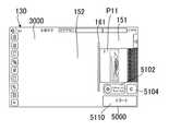
原稿が原稿読取部102に読取られると、読取られた1枚目の原稿の画像データから表示画像生成手段137により縮小された表示画像が生成されて、図32に示すように、読取りライン161の右側の第1の表示領域151に1枚目の画像P11が表示される。このとき、動作モードとしてファクシミリモードが選択されているので、プレビュー表示される画像は全てモノクロ画像で表示される。 When the original is read by the
1枚目の画像P11は、第2の表示領域152に向って、すなわち読取りライン161に向って(右側から左側に向って)徐々に画像が明瞭となるように表示されている。 The first image P11 is displayed toward the
第1の表示領域151に表示された1枚目の画像P11は、図33に示すように、読取りライン161に向って移動して、図34に示すように、読取りライン161を通って読取りライン161の左側の第2の表示領域152に移動して表示される。
このとき、第1の表示領域151には、原稿読取部102に読取られた2枚目の原稿の画像データから表示画像生成手段137により生成された2枚目の画像P12が縮小されて表示される。The first image P11 displayed in the
At this time, in the
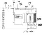
第1の表示領域151に表示される2枚目の画像P12は、第2の表示領域152に向って、すなわち読取りライン161に向って(右側から左側に向って)徐々に画像が明瞭となるように表示されている。 The second image P12 displayed in the
そして、第1の表示領域151に表示された2枚目の画像P12は、図35に示すように、読取りライン161に向って移動して、図36に示すように、読取りライン161を通って読取りライン161の左側の第2の表示領域152に移動して表示される。
このとき、2枚目の画像P12は、1枚目の画像P11の背後に重ねて配置され、2枚目の画像P12の存在が確認できるように一部を1枚目の画像P11の下から露出した状態で配置される。Then, the second image P12 displayed in the
At this time, the second image P12 is arranged so as to be overlapped behind the first image P11, and a part thereof is placed from below the first image P11 so that the existence of the second image P12 can be confirmed. It is placed in an exposed state.
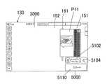
そして、このとき、第1の表示領域151には、原稿読取部102に読取られた3枚目の原稿の画像データから表示画像生成手段137により生成された3枚目の画像P13が縮小されて表示される。 Then, at this time, the third image P13 generated by the display image generation means 137 from the image data of the third document read by the
第1の表示領域151に表示される3枚目の画像P13は、第2の表示領域152に向って、すなわち読取りライン161に向って(右側から左側に向って)徐々に画像が明瞭となるように表示されている。 The third image P13 displayed in the
そして、第1の表示領域151に表示された3枚目の画像P13は、読取りライン161に向って移動して、図37に示すように、読取りライン161を通って読取りライン161の左側の第2の表示領域152に移動して表示される。そして、3枚目の画像P13は、2枚目の画像P12の背後にさらに重ねて配置され、3枚目の画像P13の存在が確認できるように一部を2枚目の画像P12の下から露出した状態で配置される。 Then, the third image P13 displayed in the
以上のように、原稿読取部102により読取られた原稿の表示画像の表示と移動が繰り返されて、全ての原稿のスキャンインによる事前読込が完了すると、図38,図39に示すように、機能設定領域2000とアクションパネル領域4000の表示がもとの状態に戻されるとともに、読取りライン161が消去される。 As described above, when the display and movement of the display image of the document read by the
このようにして、ファクシミリモードにおいて、原稿をA4横送りにセットした場合に原稿がA4横送りで読取られる状況をタッチパネルディスプレイ130上で容易に確認することができ、FAX送信される画像がモノクロ画像であることが容易に確認することができる。 In this way, in the facsimile mode, when the document is set in A4 landscape feed, the situation in which the document is read in A4 landscape feed can be easily confirmed on the
以上のように構成したので、本実施形態によれば、画像形成装置100において、表示画像生成手段137により、蓄積手段105に蓄積された画像データがカラーの画像データの場合は、その画像データの縮小されたカラー画像とモノクロ画像を表示画像として生成して、操作ユニット側制御部131により、複数の動作モードから選択された動作モードに対応した表示画像を表示パネル132にプレビュー表示するようにしたので、ファクシミリモードやインターネットファクシミリモードが単独で、もしくは複数の動作モードが選択されているなかで主モードとして選択されている場合に、読込原稿がカラー原稿であっても、原稿の読込み中のプレビュー表示及び読込完了後の仕上りプレビュー表示の画像をモノクロ画像で表示することができるため、煩雑な操作を行うことなく、実際に送信する画像のイメージを即座に確認することできる。 According to the present embodiment, when the image data stored in the storage means 105 by the display image generation means 137 in the
また、本実施形態によれば、読込んだ画像を確認したい場合でも、プレビュー表示を原稿表示モードに切り替えることで、読込んだままの原稿(カラー原稿の場合はカラー画像)の縮小画像で確認することができる。 Further, according to the present embodiment, even when it is desired to confirm the read image, by switching the preview display to the original display mode, the read original (color image in the case of a color original) is confirmed as a reduced image. can do.
尚、上述した実施形態では、本発明に係る操作ユニット120を図1に示すような画像形成装置100に適用した例について説明したが、FAX送信(またはインターネットFAX送信)する前に表示パネル等に原稿画像をプレビュー表示が可能な操作ユニットを備えるものであれば、上述したような構成の画像形成装置や複写機に限定されるものではなく、その他のデジタル複合機等に展開が可能である。 In the above-described embodiment, an example in which the
以上のように、本発明は、上述した実施形態に限定されるものではなく、請求項に示した範囲で種々の変更が可能である。当業者であれば、特許請求の範囲に記載された範疇内において、各種の変更例または修正例に想到し得ることは明らかであり、すなわち、本発明の要旨を逸脱しない範囲内において適宜変更した技術的手段を組み合わせて得られる実施形態についても本発明の技術的範囲に含まれる。 As described above, the present invention is not limited to the above-described embodiment, and various modifications can be made within the scope of the claims. It is clear that a person skilled in the art can come up with various modifications or modifications within the scope of the claims, that is, the modifications are made as appropriate without departing from the gist of the present invention. Embodiments obtained by combining technical means are also included in the technical scope of the present invention.
100 画像形成装置
101 主制御部
102 原稿読取部(入力手段)
103 画像処理手段
104 画像形成部(画像形成手段)
105 蓄積手段
107 画像出力手段
120 操作ユニット(画像表示操作装置)
130 タッチパネルディスプレイ(表示制御手段)
131 操作ユニット側制御部
132 表示パネル(表示手段)
134 タッチパネル
135 操作位置検出手段
136 画面表示手段
137 表示画像生成手段
151 第1の表示領域
152 第2の表示領域
161 読取りライン(境界ライン)
1000 システム領域
1310 表示画像表示手段
1311 第1の表示領域表示手段
1312 第2の表示領域表示手段
1000 システム領域
2000 機能選択領域
3000 プレビュー領域
4000 アクションパネル領域
5000 タスクトリガー領域
5100 実行ボタン群
5102 スキャンインキー(操作キー)
5104 クリアオールキー(操作キー)
5106 モノクロスタートキー(操作キー)
5108 カラースタートキー(操作キー)
5109 中断キー(操作キー)
5110 スタートキー(操作キー)
P1,P11 1枚目の画像
P2,P12 2枚目の画像
P3,P13 3枚目の画像100
103 Image processing means 104 Image forming unit (image forming means)
105 Storage means 107 Image output means 120 Operation unit (image display operation device)
130 Touch panel display (display control means)
131 Operation unit
134
1000
5104 Clear all key (operation key)
5106 Monochrome start key (operation key)
5108 Color start key (operation key)
5109 Suspend key (operation key)
5110 Start key (operation key)
P1, P11 1st image P2, P12 2nd image P3, P13 3rd image
Claims (5)
Translated fromJapanese複数の動作モードを選択可能に備え、
主モードとしてファクシミリモード又はインターネットファクシミリモードが選択されるとともに、副モードとしてコピーモード又はE-mail送信モードが選択された場合、読み込まれた原稿画像の色調に関わらず、仕上がりプレビューを表示するときには、モノクロ画像を表示することを特徴とする画像形成装置。In an image forming apparatus that generates a display image based on a read original image and previews the generated display image.
With multiple operation modes selectable
When the facsimile mode or the Internet facsimile mode is selected as the main mode and the copy mode or the E-mail transmission mode is selected as the sub mode, when displaying the finished preview regardless of the color tone of the read original image, An image forming apparatus characterized by displaying a monochrome image.
複数の動作モードを選択可能に備え、
主モードとしてファクシミリモード又はインターネットファクシミリモードが選択された場合、仕上がりプレビュー表示をするときには、読み込まれた原稿画像の色調に関わらず、モノクロ画像を表示し、
主モードとしてコピーモード又はE-mail送信モードが選択されるとともに、副モードとしてファクシミリモード又はインターネットファクシミリモードが選択された場合、仕上がりプレビューを表示するときには、機能設定に応じた色調の表示画面を表示することを特徴とする画像形成装置。In an image forming apparatus that generates a display image based on a read original image and previews the generated display image.
With multiple operation modes selectable
When the facsimile mode or the Internet facsimile mode is selected as the main mode, a monochrome image is displayed regardless of the color tone of the read original image when the finished preview is displayed.
When copy modeor E-mail transmission modeis selectedas the main mode and facsimile mode or internet facsimile mode is selectedas thesub mode, when displaying the finished preview, the display screen of the color tone according to the function setting is displayed. An image forming apparatus characterized by
複数の動作モードを選択可能に備え、
主モードとしてファクシミリモード又はインターネットファクシミリモードが選択されるとともに、副モードとしてコピーモード又はE-mail送信モードが選択された場合、読み込まれた原稿画像の色調に関わらず、仕上がりプレビューを表示するときには、モノクロ画像を表示する、
ことを特徴とする画像形成装置のプレビュー表示方法。In the preview display method of the image forming apparatus that generates a display image based on the read original image and previews the generated display image.
With multiple operation modes selectable
When the facsimile mode or the Internet facsimile mode is selected as the main mode and the copy mode or the E-mail transmission mode is selected as the sub mode, when displaying the finished preview regardless of the color tone of the read original image, Display monochrome images ,
A method of displaying a preview of an image forming apparatus.
複数の動作モードを選択可能に備え、 With multiple operation modes selectable
主モードとしてファクシミリモード又はインターネットファクシミリモードが選択された場合、仕上がりプレビュー表示をするときには、読み込まれた原稿画像の色調に関わらず、モノクロ画像を表示し、 When the facsimile mode or the Internet facsimile mode is selected as the main mode, a monochrome image is displayed regardless of the color tone of the read original image when the finished preview is displayed.
主モードとしてコピーモード又はE-mail送信モードが選択されるとともに、副モードとしてファクシミリモード又はインターネットファクシミリモードが選択された場合、仕上がりプレビューを表示するときには、機能設定に応じた色調の表示画面を表示する、 When copy mode or E-mail transmission mode is selected as the main mode and facsimile mode or internet facsimile mode is selected as the sub mode, when displaying the finished preview, the display screen of the color tone according to the function setting is displayed. To do
ことを特徴とする画像形成装置のプレビュー表示方法。 A method of displaying a preview of an image forming apparatus.
Priority Applications (1)
| Application Number | Priority Date | Filing Date | Title |
|---|---|---|---|
| JP2019118293AJP6768885B2 (en) | 2019-06-26 | 2019-06-26 | Image forming device and preview display method of image forming device |
Applications Claiming Priority (1)
| Application Number | Priority Date | Filing Date | Title |
|---|---|---|---|
| JP2019118293AJP6768885B2 (en) | 2019-06-26 | 2019-06-26 | Image forming device and preview display method of image forming device |
Related Parent Applications (1)
| Application Number | Title | Priority Date | Filing Date |
|---|---|---|---|
| JP2017224649ADivisionJP6695316B2 (en) | 2017-11-22 | 2017-11-22 | Image forming apparatus and preview display method for image forming apparatus |
Publications (2)
| Publication Number | Publication Date |
|---|---|
| JP2019201412A JP2019201412A (en) | 2019-11-21 |
| JP6768885B2true JP6768885B2 (en) | 2020-10-14 |
Family
ID=68613313
Family Applications (1)
| Application Number | Title | Priority Date | Filing Date |
|---|---|---|---|
| JP2019118293AActiveJP6768885B2 (en) | 2019-06-26 | 2019-06-26 | Image forming device and preview display method of image forming device |
Country Status (1)
| Country | Link |
|---|---|
| JP (1) | JP6768885B2 (en) |
Family Cites Families (4)
| Publication number | Priority date | Publication date | Assignee | Title |
|---|---|---|---|---|
| JP2008294606A (en)* | 2007-05-23 | 2008-12-04 | Murata Mach Ltd | Image processor |
| JP4708460B2 (en)* | 2008-08-27 | 2011-06-22 | シャープ株式会社 | Display control apparatus, image forming apparatus, display device control method, control program, and recording medium |
| JP5101463B2 (en)* | 2008-11-19 | 2012-12-19 | シャープ株式会社 | Image reading apparatus, image forming apparatus, image reading apparatus control method, control program, and recording medium |
| JP2010183456A (en)* | 2009-02-06 | 2010-08-19 | Sharp Corp | Image processor, image reading processing apparatus, image forming apparatus, image processing method, image processing program, and recording medium |
- 2019
- 2019-06-26JPJP2019118293Apatent/JP6768885B2/enactiveActive
Also Published As
| Publication number | Publication date |
|---|---|
| JP2019201412A (en) | 2019-11-21 |
Similar Documents
| Publication | Publication Date | Title |
|---|---|---|
| JP5192019B2 (en) | Image forming apparatus | |
| CN104506748B (en) | Image forming apparatus | |
| JP5646898B2 (en) | Image forming apparatus | |
| JP4943527B2 (en) | Image display operation device and image forming apparatus having the same | |
| JP2012022188A (en) | Image forming apparatus | |
| JP4975129B2 (en) | Operating device, electronic device and image processing apparatus including the operating device, and information display method in the operating device | |
| JP5101672B2 (en) | Image forming apparatus | |
| JP5587099B2 (en) | Image forming apparatus | |
| JP2012095001A (en) | Image forming apparatus | |
| JP6437064B2 (en) | Image forming apparatus | |
| JP5653106B2 (en) | Image transmission device | |
| JP2016048965A (en) | Image transmitting apparatus, image transmitting method, and image forming apparatus provided with image transmitting apparatus | |
| JP6351793B2 (en) | Image transmitting apparatus, image transmitting method, and image forming apparatus provided with image transmitting apparatus | |
| JP6768885B2 (en) | Image forming device and preview display method of image forming device | |
| JP5710669B2 (en) | Image forming apparatus | |
| JP6695316B2 (en) | Image forming apparatus and preview display method for image forming apparatus | |
| JP6250618B2 (en) | Image forming apparatus and preview display method of image forming apparatus | |
| JP6383054B2 (en) | Image forming apparatus and display control method for image forming apparatus | |
| JP5856253B2 (en) | Image forming apparatus and preview display method of image forming apparatus | |
| JP6824323B2 (en) | Image forming device | |
| JP6166421B2 (en) | Image forming apparatus and display control method for image forming apparatus | |
| JP5865984B2 (en) | Image transmitting apparatus and image transmitting method | |
| JP5936720B2 (en) | Image forming apparatus | |
| JP6250849B2 (en) | Image forming apparatus | |
| JP5562802B2 (en) | Image forming apparatus |
Legal Events
| Date | Code | Title | Description |
|---|---|---|---|
| A621 | Written request for application examination | Free format text:JAPANESE INTERMEDIATE CODE: A621 Effective date:20190626 | |
| A131 | Notification of reasons for refusal | Free format text:JAPANESE INTERMEDIATE CODE: A131 Effective date:20200519 | |
| A521 | Written amendment | Free format text:JAPANESE INTERMEDIATE CODE: A523 Effective date:20200715 | |
| TRDD | Decision of grant or rejection written | ||
| A01 | Written decision to grant a patent or to grant a registration (utility model) | Free format text:JAPANESE INTERMEDIATE CODE: A01 Effective date:20200825 | |
| A61 | First payment of annual fees (during grant procedure) | Free format text:JAPANESE INTERMEDIATE CODE: A61 Effective date:20200923 | |
| R150 | Certificate of patent or registration of utility model | Ref document number:6768885 Country of ref document:JP Free format text:JAPANESE INTERMEDIATE CODE: R150 |