JP6768001B2 - Coiled implants and systems and how to make them - Google Patents
Coiled implants and systems and how to make themDownload PDFInfo
- Publication number
- JP6768001B2 JP6768001B2JP2017556733AJP2017556733AJP6768001B2JP 6768001 B2JP6768001 B2JP 6768001B2JP 2017556733 AJP2017556733 AJP 2017556733AJP 2017556733 AJP2017556733 AJP 2017556733AJP 6768001 B2JP6768001 B2JP 6768001B2
- Authority
- JP
- Japan
- Prior art keywords
- implant
- coils
- coil
- level
- implants
- Prior art date
- Legal status (The legal status is an assumption and is not a legal conclusion. Google has not performed a legal analysis and makes no representation as to the accuracy of the status listed.)
- Active
Links
Images


Classifications
- A—HUMAN NECESSITIES
- A61—MEDICAL OR VETERINARY SCIENCE; HYGIENE
- A61F—FILTERS IMPLANTABLE INTO BLOOD VESSELS; PROSTHESES; DEVICES PROVIDING PATENCY TO, OR PREVENTING COLLAPSING OF, TUBULAR STRUCTURES OF THE BODY, e.g. STENTS; ORTHOPAEDIC, NURSING OR CONTRACEPTIVE DEVICES; FOMENTATION; TREATMENT OR PROTECTION OF EYES OR EARS; BANDAGES, DRESSINGS OR ABSORBENT PADS; FIRST-AID KITS
- A61F2/00—Filters implantable into blood vessels; Prostheses, i.e. artificial substitutes or replacements for parts of the body; Appliances for connecting them with the body; Devices providing patency to, or preventing collapsing of, tubular structures of the body, e.g. stents
- A61F2/02—Prostheses implantable into the body
- A61F2/30—Joints
- A61F2/44—Joints for the spine, e.g. vertebrae, spinal discs
- A61F2/4455—Joints for the spine, e.g. vertebrae, spinal discs for the fusion of spinal bodies, e.g. intervertebral fusion of adjacent spinal bodies, e.g. fusion cages
- A—HUMAN NECESSITIES
- A61—MEDICAL OR VETERINARY SCIENCE; HYGIENE
- A61F—FILTERS IMPLANTABLE INTO BLOOD VESSELS; PROSTHESES; DEVICES PROVIDING PATENCY TO, OR PREVENTING COLLAPSING OF, TUBULAR STRUCTURES OF THE BODY, e.g. STENTS; ORTHOPAEDIC, NURSING OR CONTRACEPTIVE DEVICES; FOMENTATION; TREATMENT OR PROTECTION OF EYES OR EARS; BANDAGES, DRESSINGS OR ABSORBENT PADS; FIRST-AID KITS
- A61F2/00—Filters implantable into blood vessels; Prostheses, i.e. artificial substitutes or replacements for parts of the body; Appliances for connecting them with the body; Devices providing patency to, or preventing collapsing of, tubular structures of the body, e.g. stents
- A61F2/02—Prostheses implantable into the body
- A61F2/30—Joints
- A61F2/30721—Accessories
- A61F2/30744—End caps, e.g. for closing an endoprosthetic cavity
- A—HUMAN NECESSITIES
- A61—MEDICAL OR VETERINARY SCIENCE; HYGIENE
- A61F—FILTERS IMPLANTABLE INTO BLOOD VESSELS; PROSTHESES; DEVICES PROVIDING PATENCY TO, OR PREVENTING COLLAPSING OF, TUBULAR STRUCTURES OF THE BODY, e.g. STENTS; ORTHOPAEDIC, NURSING OR CONTRACEPTIVE DEVICES; FOMENTATION; TREATMENT OR PROTECTION OF EYES OR EARS; BANDAGES, DRESSINGS OR ABSORBENT PADS; FIRST-AID KITS
- A61F2/00—Filters implantable into blood vessels; Prostheses, i.e. artificial substitutes or replacements for parts of the body; Appliances for connecting them with the body; Devices providing patency to, or preventing collapsing of, tubular structures of the body, e.g. stents
- A61F2/02—Prostheses implantable into the body
- A61F2/30—Joints
- A61F2002/30001—Additional features of subject-matter classified in A61F2/28, A61F2/30 and subgroups thereof
- A61F2002/30003—Material related properties of the prosthesis or of a coating on the prosthesis
- A61F2002/30004—Material related properties of the prosthesis or of a coating on the prosthesis the prosthesis being made from materials having different values of a given property at different locations within the same prosthesis
- A61F2002/30011—Material related properties of the prosthesis or of a coating on the prosthesis the prosthesis being made from materials having different values of a given property at different locations within the same prosthesis differing in porosity
- A—HUMAN NECESSITIES
- A61—MEDICAL OR VETERINARY SCIENCE; HYGIENE
- A61F—FILTERS IMPLANTABLE INTO BLOOD VESSELS; PROSTHESES; DEVICES PROVIDING PATENCY TO, OR PREVENTING COLLAPSING OF, TUBULAR STRUCTURES OF THE BODY, e.g. STENTS; ORTHOPAEDIC, NURSING OR CONTRACEPTIVE DEVICES; FOMENTATION; TREATMENT OR PROTECTION OF EYES OR EARS; BANDAGES, DRESSINGS OR ABSORBENT PADS; FIRST-AID KITS
- A61F2/00—Filters implantable into blood vessels; Prostheses, i.e. artificial substitutes or replacements for parts of the body; Appliances for connecting them with the body; Devices providing patency to, or preventing collapsing of, tubular structures of the body, e.g. stents
- A61F2/02—Prostheses implantable into the body
- A61F2/30—Joints
- A61F2002/30001—Additional features of subject-matter classified in A61F2/28, A61F2/30 and subgroups thereof
- A61F2002/30108—Shapes
- A61F2002/30199—Three-dimensional shapes
- A61F2002/302—Three-dimensional shapes toroidal, e.g. rings
- A—HUMAN NECESSITIES
- A61—MEDICAL OR VETERINARY SCIENCE; HYGIENE
- A61F—FILTERS IMPLANTABLE INTO BLOOD VESSELS; PROSTHESES; DEVICES PROVIDING PATENCY TO, OR PREVENTING COLLAPSING OF, TUBULAR STRUCTURES OF THE BODY, e.g. STENTS; ORTHOPAEDIC, NURSING OR CONTRACEPTIVE DEVICES; FOMENTATION; TREATMENT OR PROTECTION OF EYES OR EARS; BANDAGES, DRESSINGS OR ABSORBENT PADS; FIRST-AID KITS
- A61F2/00—Filters implantable into blood vessels; Prostheses, i.e. artificial substitutes or replacements for parts of the body; Appliances for connecting them with the body; Devices providing patency to, or preventing collapsing of, tubular structures of the body, e.g. stents
- A61F2/02—Prostheses implantable into the body
- A61F2/30—Joints
- A61F2002/30001—Additional features of subject-matter classified in A61F2/28, A61F2/30 and subgroups thereof
- A61F2002/30108—Shapes
- A61F2002/30199—Three-dimensional shapes
- A61F2002/30289—Three-dimensional shapes helically-coiled
- A—HUMAN NECESSITIES
- A61—MEDICAL OR VETERINARY SCIENCE; HYGIENE
- A61F—FILTERS IMPLANTABLE INTO BLOOD VESSELS; PROSTHESES; DEVICES PROVIDING PATENCY TO, OR PREVENTING COLLAPSING OF, TUBULAR STRUCTURES OF THE BODY, e.g. STENTS; ORTHOPAEDIC, NURSING OR CONTRACEPTIVE DEVICES; FOMENTATION; TREATMENT OR PROTECTION OF EYES OR EARS; BANDAGES, DRESSINGS OR ABSORBENT PADS; FIRST-AID KITS
- A61F2/00—Filters implantable into blood vessels; Prostheses, i.e. artificial substitutes or replacements for parts of the body; Appliances for connecting them with the body; Devices providing patency to, or preventing collapsing of, tubular structures of the body, e.g. stents
- A61F2/02—Prostheses implantable into the body
- A61F2/30—Joints
- A61F2002/30001—Additional features of subject-matter classified in A61F2/28, A61F2/30 and subgroups thereof
- A61F2002/30316—The prosthesis having different structural features at different locations within the same prosthesis; Connections between prosthetic parts; Special structural features of bone or joint prostheses not otherwise provided for
- A61F2002/30535—Special structural features of bone or joint prostheses not otherwise provided for
- A61F2002/30593—Special structural features of bone or joint prostheses not otherwise provided for hollow
- A—HUMAN NECESSITIES
- A61—MEDICAL OR VETERINARY SCIENCE; HYGIENE
- A61F—FILTERS IMPLANTABLE INTO BLOOD VESSELS; PROSTHESES; DEVICES PROVIDING PATENCY TO, OR PREVENTING COLLAPSING OF, TUBULAR STRUCTURES OF THE BODY, e.g. STENTS; ORTHOPAEDIC, NURSING OR CONTRACEPTIVE DEVICES; FOMENTATION; TREATMENT OR PROTECTION OF EYES OR EARS; BANDAGES, DRESSINGS OR ABSORBENT PADS; FIRST-AID KITS
- A61F2/00—Filters implantable into blood vessels; Prostheses, i.e. artificial substitutes or replacements for parts of the body; Appliances for connecting them with the body; Devices providing patency to, or preventing collapsing of, tubular structures of the body, e.g. stents
- A61F2/02—Prostheses implantable into the body
- A61F2/30—Joints
- A61F2002/30001—Additional features of subject-matter classified in A61F2/28, A61F2/30 and subgroups thereof
- A61F2002/30621—Features concerning the anatomical functioning or articulation of the prosthetic joint
- A61F2002/30622—Implant for fusing a joint or bone material
- A—HUMAN NECESSITIES
- A61—MEDICAL OR VETERINARY SCIENCE; HYGIENE
- A61F—FILTERS IMPLANTABLE INTO BLOOD VESSELS; PROSTHESES; DEVICES PROVIDING PATENCY TO, OR PREVENTING COLLAPSING OF, TUBULAR STRUCTURES OF THE BODY, e.g. STENTS; ORTHOPAEDIC, NURSING OR CONTRACEPTIVE DEVICES; FOMENTATION; TREATMENT OR PROTECTION OF EYES OR EARS; BANDAGES, DRESSINGS OR ABSORBENT PADS; FIRST-AID KITS
- A61F2/00—Filters implantable into blood vessels; Prostheses, i.e. artificial substitutes or replacements for parts of the body; Appliances for connecting them with the body; Devices providing patency to, or preventing collapsing of, tubular structures of the body, e.g. stents
- A61F2/02—Prostheses implantable into the body
- A61F2/30—Joints
- A61F2/30767—Special external or bone-contacting surface, e.g. coating for improving bone ingrowth
- A61F2/30771—Special external or bone-contacting surface, e.g. coating for improving bone ingrowth applied in original prostheses, e.g. holes or grooves
- A61F2002/30772—Apertures or holes, e.g. of circular cross section
- A61F2002/30774—Apertures or holes, e.g. of circular cross section internally-threaded
- A—HUMAN NECESSITIES
- A61—MEDICAL OR VETERINARY SCIENCE; HYGIENE
- A61F—FILTERS IMPLANTABLE INTO BLOOD VESSELS; PROSTHESES; DEVICES PROVIDING PATENCY TO, OR PREVENTING COLLAPSING OF, TUBULAR STRUCTURES OF THE BODY, e.g. STENTS; ORTHOPAEDIC, NURSING OR CONTRACEPTIVE DEVICES; FOMENTATION; TREATMENT OR PROTECTION OF EYES OR EARS; BANDAGES, DRESSINGS OR ABSORBENT PADS; FIRST-AID KITS
- A61F2/00—Filters implantable into blood vessels; Prostheses, i.e. artificial substitutes or replacements for parts of the body; Appliances for connecting them with the body; Devices providing patency to, or preventing collapsing of, tubular structures of the body, e.g. stents
- A61F2/02—Prostheses implantable into the body
- A61F2/30—Joints
- A61F2/30767—Special external or bone-contacting surface, e.g. coating for improving bone ingrowth
- A61F2002/3092—Special external or bone-contacting surface, e.g. coating for improving bone ingrowth having an open-celled or open-pored structure
- A—HUMAN NECESSITIES
- A61—MEDICAL OR VETERINARY SCIENCE; HYGIENE
- A61F—FILTERS IMPLANTABLE INTO BLOOD VESSELS; PROSTHESES; DEVICES PROVIDING PATENCY TO, OR PREVENTING COLLAPSING OF, TUBULAR STRUCTURES OF THE BODY, e.g. STENTS; ORTHOPAEDIC, NURSING OR CONTRACEPTIVE DEVICES; FOMENTATION; TREATMENT OR PROTECTION OF EYES OR EARS; BANDAGES, DRESSINGS OR ABSORBENT PADS; FIRST-AID KITS
- A61F2/00—Filters implantable into blood vessels; Prostheses, i.e. artificial substitutes or replacements for parts of the body; Appliances for connecting them with the body; Devices providing patency to, or preventing collapsing of, tubular structures of the body, e.g. stents
- A61F2/02—Prostheses implantable into the body
- A61F2/30—Joints
- A61F2/3094—Designing or manufacturing processes
- A61F2/30942—Designing or manufacturing processes for designing or making customized prostheses, e.g. using templates, CT or NMR scans, finite-element analysis or CAD-CAM techniques
- A61F2002/30957—Designing or manufacturing processes for designing or making customized prostheses, e.g. using templates, CT or NMR scans, finite-element analysis or CAD-CAM techniques using a positive or a negative model, e.g. moulds
- A—HUMAN NECESSITIES
- A61—MEDICAL OR VETERINARY SCIENCE; HYGIENE
- A61F—FILTERS IMPLANTABLE INTO BLOOD VESSELS; PROSTHESES; DEVICES PROVIDING PATENCY TO, OR PREVENTING COLLAPSING OF, TUBULAR STRUCTURES OF THE BODY, e.g. STENTS; ORTHOPAEDIC, NURSING OR CONTRACEPTIVE DEVICES; FOMENTATION; TREATMENT OR PROTECTION OF EYES OR EARS; BANDAGES, DRESSINGS OR ABSORBENT PADS; FIRST-AID KITS
- A61F2/00—Filters implantable into blood vessels; Prostheses, i.e. artificial substitutes or replacements for parts of the body; Appliances for connecting them with the body; Devices providing patency to, or preventing collapsing of, tubular structures of the body, e.g. stents
- A61F2/02—Prostheses implantable into the body
- A61F2/30—Joints
- A61F2/3094—Designing or manufacturing processes
- A61F2002/30985—Designing or manufacturing processes using three dimensional printing [3DP]
- A—HUMAN NECESSITIES
- A61—MEDICAL OR VETERINARY SCIENCE; HYGIENE
- A61F—FILTERS IMPLANTABLE INTO BLOOD VESSELS; PROSTHESES; DEVICES PROVIDING PATENCY TO, OR PREVENTING COLLAPSING OF, TUBULAR STRUCTURES OF THE BODY, e.g. STENTS; ORTHOPAEDIC, NURSING OR CONTRACEPTIVE DEVICES; FOMENTATION; TREATMENT OR PROTECTION OF EYES OR EARS; BANDAGES, DRESSINGS OR ABSORBENT PADS; FIRST-AID KITS
- A61F2/00—Filters implantable into blood vessels; Prostheses, i.e. artificial substitutes or replacements for parts of the body; Appliances for connecting them with the body; Devices providing patency to, or preventing collapsing of, tubular structures of the body, e.g. stents
- A61F2/02—Prostheses implantable into the body
- A61F2/30—Joints
- A61F2/44—Joints for the spine, e.g. vertebrae, spinal discs
- A61F2002/4495—Joints for the spine, e.g. vertebrae, spinal discs having a fabric structure, e.g. made from wires or fibres
Landscapes
- Health & Medical Sciences (AREA)
- Engineering & Computer Science (AREA)
- Biomedical Technology (AREA)
- Orthopedic Medicine & Surgery (AREA)
- Neurology (AREA)
- Heart & Thoracic Surgery (AREA)
- Oral & Maxillofacial Surgery (AREA)
- Transplantation (AREA)
- Cardiology (AREA)
- Vascular Medicine (AREA)
- Life Sciences & Earth Sciences (AREA)
- Animal Behavior & Ethology (AREA)
- General Health & Medical Sciences (AREA)
- Public Health (AREA)
- Veterinary Medicine (AREA)
- Prostheses (AREA)
- Surgical Instruments (AREA)
Description
Translated fromJapanese本発明は、一般に、患者における骨成長を支持するインプラントに関する。 The present invention generally relates to implants that support bone growth in patients.
種々の異なるインプラントが体内で使用される。あるエリアを安定させ、骨内部成長を促すように体内で使用されるインプラントは、安定性(すなわち、経時にわたる圧力下での最小限の変形)および骨内部成長のスペースの双方を提供する。 A variety of different implants are used in the body. Implants used in the body to stabilize an area and promote internal bone growth provide both stability (ie, minimal deformation under pressure over time) and space for internal bone growth.
脊椎固定術または脊椎癒着術としても知られている脊椎固定は、変性円板疾患、すべり症(椎骨のすべり)、脊柱管狭窄症、脊柱側弯症、骨折、感染または腫瘍等の、種々の病的状態の治療に使用される外科的な治療方法である。脊椎固定処置の目的は、不安定さ、ひいては痛みを低減することである。 Spinal fusion, also known as spinal fusion or spinal fusion, is a variety of diseases such as degenerative disc disease, spondylolisthesis (slip of the vertebrae), spinal canal stenosis, scoliosis, fractures, infections or tumors. A surgical treatment method used to treat a condition. The purpose of spinal fusion procedures is to reduce instability and thus pain.
脊椎固定に備えて、椎間板のほとんどが除去される。デバイス、すなわち脊椎固定ケージ、を椎骨間に配置して、脊椎の位置合わせおよび椎間板の高さを維持してもよい。癒合、すなわち骨橋は、椎骨の終板間で生じる。 Most of the disc is removed in preparation for spinal fusion. A device, a spinal fixation cage, may be placed between the vertebrae to maintain spinal alignment and disc height. Fusion, or osteopontin, occurs between the endplates of the vertebrae.
しかし、骨内部成長のためにインプラント内にスペースを設けることは、インプラントの強度および安定性を損なう可能性がある。 However, providing space within the implant for internal bone growth can compromise the strength and stability of the implant.
圧力および張力下でインプラントの形状を維持するとともに、骨内部成長のための十分な開口を提供する、改良されたインプラントが必要とされている。 There is a need for improved implants that maintain the shape of the implant under pressure and tension and provide sufficient opening for internal bone growth.
本発明の目的は、改良されたインプラントを提供することである。 An object of the present invention is to provide an improved implant.
本発明のさらなる目的は、患者の骨を修復するかまたは患者における骨の癒合を生成するシステムを提供することである。 A further object of the present invention is to provide a system for repairing a patient's bone or producing bone fusion in the patient.
本発明のまたさらなる目的は、そのようなインプラントを製造する方法を提供することである。 Yet a further object of the present invention is to provide a method of making such an implant.
インプラント、システム、ならびに、そのようなインプラントを作製および使用する方法が、本明細書において記載される。インプラントは、1つまたは複数のコイル、好ましくは複数のコイルから形成される。いくつかの実施形態では、インプラントの壁は複数のコイルから形成され、任意選択的に、コイルは、2つ以上のコイルの、セットまたは群に含まれる。 Implants, systems, and methods for making and using such implants are described herein. The implant is formed from one or more coils, preferably multiple coils. In some embodiments, the wall of the implant is formed from a plurality of coils and optionally the coils are included in a set or group of two or more coils.
コイルのそれぞれのセットにおけるコイルは、互いに接触しないように位置合わせされる。しかし、通常、インプラントは、互いに隣接して1つまたは複数の交差領域において、通常は一定の間隔で互いに交差する少なくとも2個のコイル(またはコイルのセットもしくは群)を含む。コイルは、複数の交差領域、任意選択的には交差領域のアレイに沿って交差してもよい。交差領域は大略的に、隣接する上側または下側の骨表面に接触する、インプラントの上側表面または下側表面には位置付けられない。むしろ、交差領域は大略的に、インプラントの内部、および/または、インプラントの側壁に位置付けられる。 The coils in each set of coils are aligned so that they do not touch each other. However, implants usually include at least two coils (or a set or group of coils) that intersect each other, usually at regular intervals, in one or more intersecting regions adjacent to each other. The coils may intersect along an array of multiple intersecting regions, optionally the intersecting regions. The intersecting region is generally not located on the superior or inferior surface of the implant, which contacts the adjacent superior or inferior bone surface. Rather, the crossing region is roughly located inside the implant and / or on the side wall of the implant.
任意選択的に、インプラントは、固定および/または挿入を助ける1つまたは複数のプレートを含む。いくつかの実施形態では、インプラントは、側壁のうちの1つの代わりにプレートを含む。他の実施形態では、1つまたは複数のプレートは、側壁またはインプラントの角部に取り付けられるとともにこれと一体である。これらの実施形態では、プレートは、壁の一部のみにある。プレートは、挿入器具が嵌まる1つまたは複数の領域を含んでもよい。代替的または付加的に、プレートは、骨ねじまたは他の固定デバイスのための1つまたは複数の穴を含んでもよい。プレートは好ましくは、ケージと一体である。たとえば、プレートおよびケージは、3Dプリントを使用して1つのプロセスで製造することができる。任意選択的に、プレートは、別個に製造され、ケージに取り付けられるように構成されている。 Optionally, the implant comprises one or more plates that aid in fixation and / or insertion. In some embodiments, the implant comprises a plate instead of one of the sidewalls. In other embodiments, one or more plates are attached to and integral with the sidewalls or corners of the implant. In these embodiments, the plate is only part of the wall. The plate may include one or more areas into which the insert device fits. Alternatively or additionally, the plate may include one or more holes for bone screws or other fixation devices. The plate is preferably integral with the cage. For example, plates and cages can be manufactured in one process using 3D printing. Optionally, the plates are manufactured separately and configured to be attached to the cage.
システムは、任意選択的に1つまたは複数の固定要素を有する、1つまたは複数のインプラントを含む。任意選択的に、システムは、インプラント内に骨移植片または骨移植片代用品を含む。 The system comprises one or more implants optionally having one or more fixation elements. Optionally, the system includes a bone graft or bone graft substitute within the implant.
インプラントは、部位を修復するために骨成長を必要とする体内の種々の異なるスペースにおいて使用されるように構成することができる。一実施形態では、インプラントは、脊椎固定におけるように、脊椎において使用されるように構成されている。別の実施形態では、インプラントは、関節において使用されるように構成されている。任意選択的に、インプラントは、足首または足における骨折を修復するため等に、この領域において使用されるように構成されている。あるいは、インプラントは、大関節(たとえば、臀部および/もしくは膝インプラント)、小関節(たとえば、肩、肘および/もしくは足首インプラント)、外傷の部位(たとえば、肩の骨折、長骨再建インプラントおよび/もしくは髄内ロッド/釘インプラント)、頭蓋顎顔面(たとえば、顎置換もしくは頭蓋再建において使用するためのインプラント)、または、口内(たとえば、歯科インプラント)においてまたは隣接して使用するため等の、体内の他の部位のために構成することができる。 Implants can be configured to be used in a variety of different spaces in the body that require bone growth to repair the site. In one embodiment, the implant is configured to be used in the spine, as in spinal fusion. In another embodiment, the implant is configured for use in a joint. Optionally, the implant is configured to be used in this area, such as to repair a fracture in the ankle or foot. Alternatively, the implants can be large joints (eg, buttocks and / or knee implants), small joints (eg, shoulder, elbow and / or ankle implants), sites of trauma (eg, shoulder fractures, long bone reconstruction implants and / or). Intramedullary rod / nail implants), craniofacial (eg, implants for use in jaw replacement or reconstructive), or in the mouth (eg, dental implants) or elsewhere in the body. Can be configured for the site of.
I.インプラント
A.構造
インプラントは、体内で高い圧縮力下にあっても十分な強度および安定性を提供しながらも、骨成長のためのインプラント内の十分な開スペースを提供するように構成されている。I. Implant A. Structural implants are configured to provide sufficient open space within the implant for bone growth while providing sufficient strength and stability under high compressive forces in the body.
インプラントは、1つまたは複数のコイル、通常は複数のコイルから形成される。好ましくは、インプラント内のコイルは、十分な構造支持を提供するように十分な量およびパッキング密度で互いに対する向きにされ、それによって、インプラントは、ヒトの脊柱に加えられる標準的な荷重に晒されたとき等に、経時にわたる一定の荷重下で撓みに抵抗する。好ましくは、インプラントは、頸椎の圧縮限界点に大略的に対応する、約630lbf〜940lbfまでの荷重等の、より高い荷重か、または、単一の椎体の圧縮強度および腰椎の圧縮限界点に大略的に対応する、約8kN(1800lbf)までの荷重等のより高い荷重に晒されたときに、撓みに抵抗する。Implants are formed from one or more coils, usually multiple coils. Preferably, the coils in the implant are oriented relative to each other in sufficient quantity and packing density to provide sufficient structural support, whereby the implant is exposed to standard loads applied to the human spinal column. It resists bending under a constant load over time. Preferably, the implant will generally-corresponding to the compression limit point of cervical, load such as up to about 630lbf ~940lbf, or higher loads, or compression limit of compressive strength and lumbar single vertebral body It resists deflection when exposed to higher loads, such as loads up to about 8 kN (1800 lbf ), which roughly correspond to the points.
インプラントは、インプラントが使用される特定の部位に合わせて任意の好適な形状およびサイズを有することができる。頸椎において使用されるインプラントの場合、冠状面におけるインプラントの幅は、およそ10mm〜22mmに及び、矢状面におけるインプラントの寸法は、およそ8mm〜16mmに及び、インプラントの高さは約5mm〜40mmに及ぶ。胸椎において使用されるインプラントの場合、冠状面におけるインプラントの幅は、およそ23mm〜34mmに及び、矢状面におけるインプラントの寸法は、およそ16mm〜27mmに及び、インプラントの高さは約6mm〜53mmに及ぶ。腰椎において使用されるインプラントの場合、冠状面におけるインプラントの幅はおよそ24mm〜46mmに及び、矢状面におけるインプラントの寸法は、およそ20mm〜40mmに及び、インプラントの高さは、約6mm〜60mmに及ぶ。 The implant can have any suitable shape and size for the particular site where the implant will be used. For implants used in the cervical spine, the width of the implant in the coronal plane ranges from approximately 10 mm to 22 mm, the size of the implant in the sagittal plane ranges from approximately 8 mm to 16 mm, and the height of the implant ranges from approximately 5 mm to 40 mm. It reaches. For implants used in the thoracic spine, the width of the implant in the coronal plane ranges from approximately 23 mm to 34 mm, the size of the implant in the sagittal plane ranges from approximately 16 mm to 27 mm, and the height of the implant ranges from approximately 6 mm to 53 mm. It reaches. For implants used in the lumbar spine, the width of the implant in the coronal plane ranges from approximately 24 mm to 46 mm, the size of the implant in the sagittal plane ranges from approximately 20 mm to 40 mm, and the height of the implant ranges from approximately 6 mm to 60 mm. It reaches.
大関節(たとえば、臀部および/もしくは膝インプラント)、小関節(たとえば、肩、肘および/もしくは足首インプラント)、外傷の部位(たとえば、肩の骨折、長骨再建インプラントおよび/もしくは髄内ロッド/釘インプラント)、頭蓋顎顔面(たとえば、顎置換もしくは頭蓋再建において使用するためのインプラント)、または、口内(たとえば、歯科インプラント)において使用するため等の、体の他の部分において使用されるインプラントの場合、典型的な寸法は、これらの部位において使用されている現在のインプラントに大略的に対応する。 Large joints (eg, buttocks and / or knee implants), small joints (eg, shoulder, elbow and / or ankle implants), sites of trauma (eg, shoulder fractures, long bone reconstruction implants and / or intramedullary rods / nails) For implants used in other parts of the body, such as (implants), craniofacial (eg, implants for use in jaw replacement or reconstructive), or in the mouth (eg, dental implants). The typical dimensions roughly correspond to the current implants used at these sites.
インプラントは、1つまたは複数の平面を中心に対称であってもよい。本明細書において用いられる場合、「正中面」という用語は、インプラントを右側半体および左側半体に分ける、インプラントの前方端から後方端に通る垂直面を指す。本明細書において用いられる場合、「横断面」という用語は、インプラントを上側半体および下側半体に分ける、インプラントの中心に位置付けられる水平面を指す。本明細書において用いられる場合、「冠状面」という用語は、インプラントを前方半体および後方半体に分ける、インプラントの中心に位置付けられる垂直面を指す。いくつかの実施形態では、インプラントは、正中面および横断面等の2つの平面を中心に対称である。 The implant may be symmetrical about one or more planes. As used herein, the term "midline" refers to the vertical plane that divides the implant into right and left halves, passing from the anterior end to the posterior end of the implant. As used herein, the term "cross section" refers to the centrally located horizontal plane of the implant that divides the implant into upper and lower halves. As used herein, the term "coronal plane" refers to the centrally located vertical plane of the implant that divides the implant into anterior and posterior halves. In some embodiments, the implant is symmetrical about two planes, such as the median plane and the cross section.
任意選択的に、インプラントの1つまたは複数の部分は、骨の表面に対する摩擦を増大させ、および/または、骨移植片の成長を促すように、テクスチャー加工されたまたは多孔質の表面を含む。いくつかの実施形態では、上側面および下側面、支持体および内側壁を含む任意の内側面には、テクスチャー加工されたまたは多孔質の表面を3Dプリントしてもよい。さらなる実施形態では、インプラント全体には、任意選択的に、前方プレート、後方プレートおよび/または側壁を含む外周リングの外側表面を除いて、テクスチャー加工されるかまたは多孔質の表面が3Dプリントされる。 Optionally, one or more portions of the implant include a textured or porous surface to increase friction against the surface of the bone and / or promote the growth of the bone graft. In some embodiments, any inner surface, including upper and lower surfaces, supports and inner walls, may be 3D printed with a textured or porous surface. In a further embodiment, the entire implant is optionally 3D printed with a textured or porous surface, except for the outer surface of the outer ring, which includes the anterior plate, posterior plate and / or sidewall. ..
1.コイル
インプラントは1つまたは複数のコイルを含む。通常、インプラントは複数のコイルを含む。たとえば、コイルの2つ以上、任意選択的にはすべては、同じ寸法を有してもよい(たとえば、コイルの外径(D1)および内径(D2)、ピッチ(p)、コイルの断面の最大寸法(α)ならびに長さ(l)、図1を参照のこと)。他の実施形態では、インプラント内のコイルは様々な寸法を有してもよい。いくつかの実施形態では、1つまたは複数のより小径のコイルが、インプラント内の1つまたは複数のより大きいコイル内に位置付けられるとともに囲まれる。1. 1. Coil implants include one or more coils. Implants usually include multiple coils. For example, two or more of the coils, optionally all of them, may have the same dimensions (eg, coil outer diameter (D1) and inner diameter (D2), pitch (p), maximum coil cross section. Dimension (α) and length (l), see FIG. 1). In other embodiments, the coil within the implant may have various dimensions. In some embodiments, one or more smaller diameter coils are positioned and enclosed within one or more larger coils within the implant.
さらに他の実施形態では、所与のコイルにおける寸法のうちの1つまたは複数は変えてもよく、たとえば、コイルの外径(D1)および/または内径(D2)は、コイルの長さにわたって変えてもよい。一実施形態では、コイルが円形のらせんコイルであり、D1=D2(本明細書ではDと称される)である場合、直径(D)は、コイルの中央において直径が最も大きく、コイルの端のそれぞれにおいて直径が最も小さい状態で、テーパー状になる。別の実施形態では、コイルの直径は、インプラントの前方端においてインプラント内の1つまたは複数のコイルの直径(D)が最も大きく、インプラントの後方端において直径が最も小さい状態で、テーパー状になる。さらに他の実施形態では、インプラント内の1つまたは複数のコイルの最大の直径は、インプラントの後方端にあり、最小の直径はインプラントの前方端にある。さらに他の実施形態では、コイルの最大の直径(D)は、インプラントの1つの端付近に位置付けてもよいが、正確にインプラントの端には位置付けられなくてもよい。たとえば、コイルの最大の直径(D)は、ALIF等の、椎体間固定スペーサにおけるインプラントの中央とインプラントの前方端との間に位置付けてもよく、コイルが前方端および後方端に達するまで、直径がこの領域から縮小する。この実施形態では、前方端は、後方端よりも大きい直径(D)を有する。 In yet other embodiments, one or more of the dimensions in a given coil may vary, for example, the outer diameter (D1) and / or inner diameter (D2) of the coil may vary over the length of the coil. You may. In one embodiment, when the coil is a circular spiral coil and D1 = D2 (referred to herein as D), the diameter (D) is the largest in diameter at the center of the coil and at the ends of the coil. With the smallest diameter in each of the above, it becomes tapered. In another embodiment, the coil diameter is tapered with the largest diameter (D) of one or more coils in the implant at the anterior end of the implant and the smallest diameter at the posterior end of the implant. .. In yet another embodiment, the maximum diameter of one or more coils in the implant is at the posterior end of the implant and the minimum diameter is at the anterior end of the implant. In yet another embodiment, the maximum diameter (D) of the coil may be located near one end of the implant, but may not be located exactly at the end of the implant. For example, the maximum diameter (D) of the coil may be located between the center of the implant and the anterior end of the implant in an interbody fixation spacer, such as ALIF, until the coil reaches the anterior and posterior ends. The diameter shrinks from this area. In this embodiment, the front end has a larger diameter (D) than the rear end.
さらに、ピッチを、コイルの長さにわたって、たとえば端のそれぞれにおいて変えてもよく、コイルは、巻線のそれぞれが近接する巻線に接触するように、きつく巻き付けてもよい。 In addition, the pitch may vary over the length of the coil, eg, at each end, and the coil may be wound tightly so that each of the windings contacts an adjacent winding.
インプラント内の1つまたは複数のコイル、コイルのセットまたはコイルの群は、インプラントの下側面または上側面に位置付けられるコイルの部分に通常は対応する、1つまたは複数の平坦な部分を含んでもよい。1つまたは複数のコイルの外側表面は、インプラントが患者の体に埋め込まれるときに隣接する骨表面の形状に一致するように構成してもよい。 One or more coils, a set of coils or a group of coils within an implant may include one or more flat portions, usually corresponding to portions of the coils located on the inferior or superior side of the implant. .. The outer surface of one or more coils may be configured to match the shape of the adjacent bone surface when the implant is implanted in the patient's body.
コイルの典型的な長さは、インプラントのサイズ、および、インプラント内のコイルの位置に依存する。たとえば、インプラントを形成するように複数回巻き付くコイルは、極めて長いものとすることができる。長さは、5mm〜100mmに及ぶことができる。しかし、より短いかまたはより長い長さを有するコイルを使用してインプラントを形成してもよい。 The typical length of the coil depends on the size of the implant and the position of the coil within the implant. For example, a coil that is wound multiple times to form an implant can be extremely long. The length can range from 5 mm to 100 mm. However, implants may be formed using coils with shorter or longer lengths.
インプラント内のコイルを形成する材料の断面の最大寸法(α)は、それぞれのコイルまたはコイルのセットもしくは群について同じであるか、または、コイルまたはコイルのセットもしくは群間で変えることができる。さらなる異なるコイルは、異なる断面形状または同じ断面形状を有することができる。 The maximum cross-sectional dimension (α) of the material forming the coils in the implant is the same for each coil or set or group of coils, or can vary between coils or sets or groups of coils. Further different coils can have different cross-sectional shapes or the same cross-sectional shape.
インプラント内のコイルを形成する材料の直径(d)は、それぞれのコイルまたはコイルのセットもしくは群について同じであるか、または、コイルまたはコイルのセットもしくは群間で変えることができる。 The diameter (d) of the material forming the coils in the implant is the same for each coil or set or group of coils, or can vary between coils or sets or groups of coils.
いくつかの実施形態では、外側コイルのセットにおけるコイルを形成する材料は、内側コイルのセットにおけるコイルを形成する材料の直径(dic)よりも大きい直径(dec)を有する。他の実施形態では、外側コイルのセットにおけるコイルを形成する材料は、内側コイルのセットにおけるコイルを形成する材料の直径(dic)よりも小さい直径(dec)である。さらに他の実施形態では、decおよびdicは等しい。好ましくは、外側コイルのセットにおけるコイルを形成する材料は、内側コイルのセットにおけるコイルを形成する材料の直径(dic)以上である直径(dec)を有し(dec≧dic)、より好ましくは、decはdicよりも大きい。In some embodiments, the material forming the coil in the set of outer coils has a diameter of the material forming the coil (dics) larger in diameter than (dec) in the set of inner coils. In other embodiments, the material forming the coil in the set of outer coils is the diameter of the material forming the coil in the set of inner coils (dics) smaller in diameter than (dec). In yet other embodiments,dec anddic are equal. Preferably, the material forming the coil in the set of outer coils has a diameter (dec ) greater than orequal to the diameter (dic ) of the material forming the coil in the set of inner coils (dec ≥dic ). morepreferably, d ec is greater thand ic.
通常、コイルを形成する材料の直径(d)は、約0.25mm〜約5mm、好ましくは1mm〜3mmに及ぶ。 Generally, the diameter (d) of the material forming the coil ranges from about 0.25 mm to about 5 mm, preferably from 1 mm to 3 mm.
通常、ピッチは約2mm〜約30mmに及ぶ。 Usually, the pitch ranges from about 2 mm to about 30 mm.
インプラントを形成するのに使用されるコイルの好適な直径(D)は、通常は少なくとも0.7mmであり、任意選択的には直径が少なくとも1mmまたは少なくとも2mmである。しかし、他の直径およびその範囲も想定される。いくつかの実施形態では、コイルの直径(D)は、約1mm〜約13mmに及ぶ。くつかの実施形態では、コイルの直径(D)は、コイルの長さに沿って変わる。任意選択的に、直径(D)は、一端における最大の直径から反対端における最小の直径まで、コイルの長さにわたって徐々に変化する。たとえば、一端において、コイルは約1mmの直径(D)を有してもよく、反対端において、コイルは約13mmの直径(D)を有してもよく、直径は、コイルの長さにわたって第1の端から第2の端に増大し、周囲の/隣接する骨の生体構造との接触を増大させる。 A suitable diameter (D) of the coil used to form the implant is usually at least 0.7 mm and optionally at least 1 mm or at least 2 mm in diameter. However, other diameters and their ranges are also envisioned. In some embodiments, the coil diameter (D) ranges from about 1 mm to about 13 mm. In some embodiments, the coil diameter (D) varies with the length of the coil. Optionally, the diameter (D) gradually varies over the length of the coil, from the largest diameter at one end to the smallest diameter at the other end. For example, at one end the coil may have a diameter (D) of about 1 mm and at the other end the coil may have a diameter (D) of about 13 mm, the diameter being the first over the length of the coil. It increases from one end to the second end, increasing contact with the biological structure of the surrounding / adjacent bone.
コイルは、端を含まない連続的な閉ループ等の任意の形態であるか、または、少なくとも第1の端および第2の端を有するコイル(本明細書では「コイル状セグメント」とも称される)であるものとすることができる。「外側コイル」という用語は、インプラントの中央に対してインプラントの最も外側の位置に位置決めされるコイル、コイルの群またはコイルのセットを指す。「内側コイル」という用語は、外側コイルに対してインプラントの中央に位置付けられるかまたは交差するものを含む、インプラントの中央の最も近くに/より近くに位置決めされる任意のコイル、コイルの群またはコイルのセットを指す。 The coil is in any form, such as a continuous closed loop without ends, or has at least a first end and a second end (also referred to herein as a "coiled segment"). Can be assumed to be. The term "outer coil" refers to a coil, group of coils or set of coils positioned at the outermost position of the implant with respect to the center of the implant. The term "inner coil" refers to any coil, group of coils or coils that are positioned closest to / closer to the center of the implant, including those that are centered or intersect with the outer coil. Refers to the set of.
「コイル状セグメント」という用語は、1つまたは複数のコイル、好ましくはコイルのセットにおける2つ以上の合同コイルまたはコイルの群における2つ以上のコイルから形成される任意の幾何学的形状のセグメントを指す。好適な幾何学的形状は、限定はされないが、円、長円、直線、および、通常は1つまたは複数の湾曲した部分を含み、任意選択的には1つまたは複数の湾曲した部分および1つまたは複数の直線的な部分の組み合わせを含む不規則的な形状を含む。「コイル状セグメント」という用語は、中断ループ、すなわち、プレートもしくは外周リング、または、隣接するコイルもしくはコイルのセットもしくは群と交差する、その他の部分では連続的なループを含む。それぞれのコイル状セグメントは、少なくとも第1の端および第2の端を有する。「外側コイル状セグメント」という用語は、インプラントの中央に対してインプラントの最も外側の位置に位置決めされるコイル状セグメントを指す。「内側コイル状セグメント」という用語は、外側コイル状セグメントに対してインプラントの中央の最も近くに/より近くに位置決めされる任意のコイル状セグメントを指す。 The term "coiled segment" refers to any geometrically shaped segment formed from one or more coils, preferably two or more congruent coils in a set of coils or two or more coils in a group of coils. Point to. Suitable geometries include, but are not limited to, circles, ellipses, straight lines, and usually one or more curved parts, optionally one or more curved parts and one. Includes irregular shapes containing a combination of one or more linear portions. The term "coiled segment" includes an interrupted loop, i.e. a plate or outer ring, or a continuous loop elsewhere that intersects an adjacent coil or set or group of coils. Each coiled segment has at least a first end and a second end. The term "outer coiled segment" refers to a coiled segment that is positioned at the outermost position of the implant with respect to the center of the implant. The term "inner coiled segment" refers to any coiled segment that is positioned closest to / closer to the center of the implant with respect to the outer coiled segment.
円弧の形態であるコイル状セグメントは、本明細書では、多くの場合に「コイル状円弧」と称される。円弧は、任意の曲線の任意の部分における任意の円の外周の任意の部分を表してもよい。コイル状円弧は通常、第1の端および第2の端を有する。コイル状円弧の第1の端および第2の端は、任意の曲線の任意の部分における任意の円の外周の任意の部分に沿って位置決めされてもよい。曲線は凹状または凸状であってもよい。「外側コイル状円弧」という用語は、インプラントの中央に対してインプラントの最も外側の位置に位置決めされるコイル状円弧を指す。「内側コイル状円弧」という用語は、インプラントの中央の最も近くに位置決めされるコイル状円弧を指す。「中間コイル状円弧」という用語は、内側コイル状円弧と外側コイル状円弧との間に位置決めされる任意のコイル状円弧を指す。 A coiled segment in the form of an arc is often referred to herein as a "coiled arc". The arc may represent any part of the outer circumference of any circle in any part of any curve. The coiled arc usually has a first end and a second end. The first and second ends of the coiled arc may be positioned along any portion of the outer circumference of any circle in any portion of any curve. The curve may be concave or convex. The term "outer coiled arc" refers to a coiled arc that is positioned at the outermost position of the implant with respect to the center of the implant. The term "inner coiled arc" refers to the coiled arc that is positioned closest to the center of the implant. The term "intermediate coiled arc" refers to any coiled arc positioned between the inner coiled arc and the outer coiled arc.
いくつかの実施形態では、インプラントは、重なり合って積み重ねられる複数のコイルを含み、インプラントの、外側側面、すなわち、壁、を画定する。たとえば、外側壁を形成するコイルのそれぞれは、連続的な閉ループの形態であってもよい。いくつかの実施形態では、インプラントの外側壁を形成するコイルのうちの1つまたは複数、任意選択的にすべては、中断ループ等のコイル状セグメントであり、2つ以上の端が、1つのプレートまたは2つ以上のプレートに取り付けられる。また、インプラントの内部は、重なり合って積み重ねられる複数のコイルで満たしてもよい。いくつかの実施形態では、インプラントの内部のそれぞれのコイルは、2つの端を有し、それぞれの端は、1つまたは複数の壁形成コイルに接触する。一実施形態では、インプラントの内部は、連続的な閉ループの形態のコイルも含み、この場合、所与のレベル(level)(すなわち、1個のコイルの幅)について、外側コイルよりも小さい寸法を有する少なくとも1個のコイルは、外側コイルと同心であり、外側コイル内に位置付けられ、外側コイルに隣接する。任意選択的に、コイルのそれぞれのレベルは、2つ以上の同心のコイルまたはコイルのセットもしくは群を含む。 In some embodiments, the implant comprises a plurality of coils that are stacked on top of each other to define the lateral aspect of the implant, i.e. the wall. For example, each of the coils forming the outer wall may be in the form of a continuous closed loop. In some embodiments, one or more of the coils forming the outer wall of the implant, optionally all, are coiled segments such as interrupted loops, with two or more ends being one plate. Or it can be attached to two or more plates. Further, the inside of the implant may be filled with a plurality of coils that are stacked on top of each other. In some embodiments, each coil inside the implant has two ends, each end contacting one or more wall forming coils. In one embodiment, the interior of the implant also includes a coil in the form of a continuous closed loop, in which case it has a smaller dimension than the outer coil for a given level (ie, the width of one coil). The at least one coil having is concentric with the outer coil, is located within the outer coil and is adjacent to the outer coil. Optionally, each level of the coil comprises two or more concentric coils or a set or group of coils.
コイル内のおよびコイル間の開口は、埋め込み後の、成長する骨のための開スペースを提供する。任意選択的に、骨移植片代用品または骨移植片材料が、埋め込み前に、埋め込みの時点で、または、埋め込み後でさえも、開口内に存在するかまたは挿入される。いくつかの実施形態では、コイルは、本明細書では中央開口と称される、インプラントの中央に通常は位置付けられる比較的大きい開スペースを画定する。中央開口は、1つの大きい開スペースであってもよい。あるいは、中央開口は、2つ以上の、より小さい開スペースに分けることができる。分けるものは、コイル、通常は複数の積み重ねられたコイルの形態であってもよく、または、任意の他の好適な形状であってもよい。 The openings in and between the coils provide open space for growing bone after implantation. Optionally, a bone graft substitute or bone graft material is present or inserted into the opening prior to implantation, at the time of implantation, or even after implantation. In some embodiments, the coil defines a relatively large open space, usually located in the center of the implant, referred to herein as the central opening. The central opening may be one large open space. Alternatively, the central opening can be divided into two or more smaller open spaces. The partition may be in the form of a coil, usually a plurality of stacked coils, or any other suitable shape.
i.量(amount)
コイルの数は、インプラントの用途に応じて変えることができる。i. Amount
The number of coils can be varied depending on the implant application.
a.コイルのセット
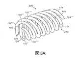
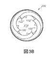
本明細書において用いられる場合、「コイルのセット」という用語は、共通のらせん軸または経路に沿って位置合わせされる2つ以上のコイルを指し、この場合、コイルは互いに交差しないかまたは接触しない。本明細書において用いられる場合、「らせん軸」は、コイルの中心にあり、その周りでコイルが回転する(図1において「Z」として特定される)直線を指す。本明細書において用いられる場合、「らせん経路」とは、コイルの中心にあり、その周りでコイルが回転する直線または湾曲した線を指す。いくつかの実施形態では、コイルのセットにおけるコイルは合同である。たとえば、図3Aおよび図3Bは、4個の合同コイル100、100’、100’’および100’’’を含むコイルのセット200を示している。a. Set of Coil As used herein, the term "set of coils" refers to two or more coils that are aligned along a common spiral axis or path, in which case the coils do not intersect each other. Or do not touch. As used herein, the "spiral axis" refers to a straight line that is in the center of the coil and around which the coil rotates (specified as "Z" in FIG. 1). As used herein, "spiral path" refers to a straight or curved line that is in the center of the coil and around which the coil rotates. In some embodiments, the coils in the set of coils are congruent. For example, FIGS. 3A and 3B show a set of 200 coils containing four combined
コイルのセットにおけるコイルは通常、互いから等間隔に離間される。たとえば、図3Aにおいて示されているように、4個のコイルがコイルのセットを形成し、この場合、セット内のすべてのコイルは、互いから等間隔に90°離間される。それぞれのコイルの端102は、隣接するコイルの端102’から90°離間して位置付けられる。図3Aにおいて示されているように、端102は端102’および端102’’から90°離間しており、端102’’は端102’’’から90°離間している。同じことが、コイルのセットの反対端において分かる。たとえば、コイル100、100’、100’’および100’’’それぞれの端104、104’、104’’および104’’’を参照のこと。所与の数(n)のコイルの等しい間隔は、360°をnで割ることによって計算することができ、したがって、3個のコイルを含むセットの場合、コイルは120°離間され、6個のコイルを含むセットの場合、コイルは60°離間される。 The coils in a set of coils are usually evenly spaced from each other. For example, as shown in FIG. 3A, four coils form a set of coils, in which case all coils in the set are evenly spaced 90 ° apart from each other. The ends 102 of each coil are positioned 90 ° apart from the ends 102'of adjacent coils. As shown in FIG. 3A, the
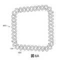
同様に、図6Aにおいて示されているように、2個のコイルがコイルのセットを形成し、この場合、セットにおけるすべてのコイルは互いから180°等間隔に離間される。どちらのコイルも、コイルのセットにおける他方のコイルに接触しない。この実施形態では、コイルのセットは、インプラントの一部を形成するのに使用することができる連続的なループの形態である。 Similarly, as shown in FIG. 6A, the two coils form a set of coils, in which case all the coils in the set are evenly spaced 180 ° apart from each other. Neither coil makes contact with the other coil in the set of coils. In this embodiment, the set of coils is in the form of a continuous loop that can be used to form part of the implant.
いくつかの実施形態では、コイルのセットにおけるコイルは、互いから等間隔で離間されない。 In some embodiments, the coils in the set of coils are not evenly spaced from each other.
b.コイルの群(group)
本明細書において用いられる場合、「コイルの群」という用語は、2つ以上のコイルを指し、この場合、少なくとも1個のコイルが少なくとも別のコイルよりも大きい直径を有し、より小さい直径を有するコイル(「内側コイル」と称される)が、より大きい直径を有する1つまたは複数のコイル(「外側コイル」と称される)の内部にある。2つ以上の内側コイルを囲む2つ以上の外側コイルを含むコイルの群の場合、外側コイルの数は通常、内側コイルの数と同じである。b. Group of coils
As used herein, the term "group of coils" refers to two or more coils, in which case at least one coil has a larger diameter than at least another coil and a smaller diameter. The coil having (referred to as "inner coil") is inside one or more coils (referred to as "outer coil") having a larger diameter. For a group of coils containing two or more outer coils surrounding two or more inner coils, the number of outer coils is usually the same as the number of inner coils.
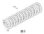
図2は、単一の外側コイル100および単一の内側コイル150を含むコイルの群500を示している。図2において示されているコイルの群は、全部で2個のコイルを含む。 FIG. 2 shows a group of
コイルの群における外側コイルおよび内側コイルは、好ましくは異なるピッチを有し、最も好ましくは、内側コイルおよび外側コイルは互い違いにまたはオフセットされて位置合わせされ、好ましくは、コイルは、約180°離間するように位置合わせされる。たとえば図2を参照のこと。 The outer and inner coils in the group of coils preferably have different pitches, most preferably the inner and outer coils are aligned alternately or offset, and preferably the coils are separated by about 180 °. Aligned so that. See, for example, Figure 2.
一定の荷重下での撓みに抵抗する強いインプラントを提供するためにコイルに密なパッキングが必要とされる場合、コイルの数は、約10個〜約100個、好ましくは約30個〜約60個に及ぶことができる。付加的に、インプラントは、第1のセットの約30個〜約60個の外側の合同コイル、および、第2のセットの約30個〜約60個の内側の合同コイルを含んでもよい。 If tight packing is required in the coils to provide a strong implant that resists bending under constant load, the number of coils will be from about 10 to about 100, preferably from about 30 to about 60. Can reach individuals. Additionally, the implant may include from about 30 to about 60 outer congruent coils in the first set and from about 30 to about 60 inner congruent coils in the second set.
たとえば、図4Aおよび図4Bは、インプラントを形成するのに使用することができるコイルの群を示している。群600は、第1のセット200の4個の外側らせんコイル100、100’、100’’および100’’’、ならびに、第2のセット400の4個の内側らせんコイル300、300’、300’’および300’’’を含む。コイルの第2のセット400はコイルの第1のセット200の内部にある。それぞれのセットにおけるコイルは合同である。図4Aおよび図4Bにおいて示されているコイルの群は、全部で8個のコイルを含む。 For example, FIGS. 4A and 4B show a group of coils that can be used to form an implant.
任意選択的に、インプラントは、第1のセットのコイルおよび第2のセットのコイル内に1つまたは複数の付加的なセットの合同コイルを含んでもよい(図示せず)。 Optionally, the implant may include one or more additional sets of combined coils within the first set of coils and the second set of coils (not shown).
ii.サイズ
インプラント内の異なるコイルは異なる直径を有してもよい。たとえば、コイルの群において、外側コイルは内側コイルよりも大きい直径を有する。ii. Size Different coils in the implant may have different diameters. For example, in a group of coils, the outer coil has a larger diameter than the inner coil.
付加的に、所与のコイルの直径はコイルに沿って変えてもよく、この場合、最大の直径がコイルの中央にあり、最小の直径が同じコイルの遠位端および近位端にあるといった具合である。あるいは、最大の直径は、コイルの一端に対応してもよく、最小の直径は、コイルの反対端に対応してもよい。 Additionally, the diameter of a given coil may vary along the coil, in which case the maximum diameter is in the center of the coil and the minimum diameter is at the distal and proximal ends of the same coil. It is in good condition. Alternatively, the maximum diameter may correspond to one end of the coil and the minimum diameter may correspond to the opposite end of the coil.
iii.形状
コイルのうちの1つまたは複数は、コイルが楕円形のコイルであるように、異なる値を有する外径(D1)および内径(D2)を有することができる。コイルのうちの1つまたは複数は、コイルが円形のらせんコイルであるように、同じ外径および内径を有する。さらに他の実施形態では、所与のコイルにおける寸法のうちの1つまたは複数を変えてもよく、たとえば、コイルの外径(D1)および/または内径(D2)を、コイルの長さにわたって変えてもよい。iii. One or more of the shape coils can have an outer diameter (D1) and an inner diameter (D2) with different values so that the coil is an elliptical coil. One or more of the coils have the same outer and inner diameters so that the coil is a circular spiral coil. In yet another embodiment, one or more of the dimensions in a given coil may be varied, eg, the outer diameter (D1) and / or inner diameter (D2) of the coil may be varied over the length of the coil. You may.
それぞれのコイルの断面は、任意の好適な形状を有することができる。断面形状は、限定はされないが、円形、楕円形、星形、正方形、矩形、長円形、六角形、八角形および非対称な形状を含む。コイルの断面の最大寸法(α)は、大略的に0.7mm以上である。たとえば、コイルの断面が円の形状である場合、円の直径(d)は通常、0.7mm以下である。たとえば図1を参照のこと。 The cross section of each coil can have any suitable shape. Cross-sectional shapes include, but are not limited to, circular, elliptical, star, square, rectangular, oval, hexagonal, octagonal and asymmetrical shapes. The maximum dimension (α) of the cross section of the coil is roughly 0.7 mm or more. For example, when the cross section of the coil is in the shape of a circle, the diameter (d) of the circle is usually 0.7 mm or less. See, for example, Figure 1.
B.インプラントの構造
インプラントは、インプラントの所望の用途に応じて任意の好適な構造を有することができる。B. Implant Structure The implant can have any suitable structure depending on the desired application of the implant.
通常、インプラントは、互いに隣接するとともに1つまたは複数の交差領域において互いに交差する少なくとも2個のコイル(またはコイルのセットもしくは群)を含む。コイルは、複数の交差領域において、任意選択的には交差領域のアレイに沿って交差してもよい。交差領域は大略的に、椎体間固定スペーサの外側の下側表面または上側表面等の、隣接する骨表面に接触するインプラントの外側表面には位置付けられない。むしろ、交差領域は、インプラントの内部および/またはインプラントの側壁に大略的に位置付けられる。 Implants typically include at least two coils (or sets or groups of coils) that are adjacent to each other and intersect each other in one or more intersecting regions. The coils may optionally intersect along an array of intersection regions in the plurality of intersection regions. The crossing region is generally not located on the lateral surface of the implant in contact with the adjacent bone surface, such as the lateral inferior or superior surface of the interbody fixation spacer. Rather, the crossing region is roughly located inside the implant and / or on the side wall of the implant.
一実施形態では、インプラントは、閉ループコイル等の複数のコイルから形成される。通常、インプラントは、2つ以上のレベル(level)を含み、この場合、それぞれのレベルは、2つ以上の閉ループコイルを含む。たとえば、2つ以上の閉ループを含むレベルにおいて、コイルのセットまたは群は、1個のコイルが他のコイルの内部にある状態で位置合わせされてレベルを形成する同心の閉ループである。通常、それぞれの閉ループは、コイルのセットの形態の2つ以上の合同コイルを含む。任意選択的に、インプラントは、1つまたは複数のプレート、および、1つまたは複数のセットの中断ループを含み、この場合、コイルの一端がプレートの一方の側に接触し、同じコイルの別の端が、同じプレートの別の側または第2のプレートの側に接触する。 In one embodiment, the implant is formed from a plurality of coils, such as a closed loop coil. Implants typically include more than one level, where each level contains more than one closed loop coil. For example, at a level involving two or more closed loops, a set or group of coils is a concentric closed loop in which one coil is aligned and forms a level with one coil inside the other coil. Usually, each closed loop comprises two or more congruent coils in the form of a set of coils. Optionally, the implant comprises one or more plates and one or more sets of interruption loops, in which one end of the coil contacts one side of the plate and another of the same coil. The end contacts the other side of the same plate or the side of the second plate.
代替的な実施形態では、インプラントは、コイル状セグメントの形態の、任意選択的にはコイル状円弧の形態等の、さらに任意選択的には1つまたは複数のプレートに接触する、複数のコイルを含む。 In an alternative embodiment, the implant comprises a plurality of coils in the form of coiled segments, optionally in the form of coiled arcs, and optionally in contact with one or more plates. Including.
代替的な実施形態では、インプラントの側壁は複数の積み重ねられた閉ループを含み、インプラントの内側部分は、コイルのスタックから形成される。コイルのそれぞれのスタックの中心は通常、スタックにおける他のコイルよりも大きい直径を有する。通常、コイルのスタックを形成するコイルは、2つ以上のコイルの複数のセットまたは群と積み重ねられる、2つ以上のコイルのセットまたは群の形態である。 In an alternative embodiment, the side wall of the implant comprises a plurality of stacked closed loops and the inner portion of the implant is formed from a stack of coils. The center of each stack of coils usually has a larger diameter than the other coils in the stack. Typically, the coils that form a stack of coils are in the form of a set or group of two or more coils that are stacked with a plurality of sets or groups of two or more coils.
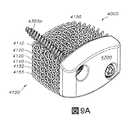
またさらなる代替的な実施形態では、インプラントは、少なくとも2個のコイル、ならびに、コイル間および/またはコイル内の開口を含む複数のコイルまたはコイルのセットを備え、この場合、インプラントは、1つまたは複数の外側壁、上側表面および下側表面、ならびに、中央支持部分を備える。中央支持部分は、外側壁の内部にある。上側表面および下側表面は、複数のコイルまたはコイルのセットから形成される。外側壁は、交差領域における2つ以上の外側コイルまたは外側コイルのセットの交差から形成される。外側壁は好ましくは、平滑な外周リングの形態である。 In a further alternative embodiment, the implant comprises at least two coils and a plurality of coils or a set of coils including openings between and / or in the coils, in which case the implant is one or more. It has a plurality of outer walls, upper and lower surfaces, and a central support portion. The central support is inside the outer wall. The upper surface and the lower surface are formed from a plurality of coils or a set of coils. The outer sidewall is formed from the intersection of two or more outer coils or a set of outer coils in the intersection region. The outer sidewall is preferably in the form of a smooth outer ring.
好ましい実施形態では、インプラントは、1つまたは複数の対称面を中心に対称である。好ましい実施形態では、インプラントは、正中面Mおよび横断面Tの双方を中心に対称である。 In a preferred embodiment, the implant is symmetric about one or more planes of symmetry. In a preferred embodiment, the implant is symmetrical about both the median plane M and the cross section T.
いくつかの実施形態では、インプラントの外側面および内側面は平滑ではなく、むしろ、テクスチャー加工されているかまたは多孔質である。しかし、通常は、外周リング、および、外周リングに取り付けられるかまたは外周リングに組み込まれるプレート等の側壁は平滑であり、すなわち、テクスチャー加工されずおよび/または多孔質ではない。 In some embodiments, the outer and inner surfaces of the implant are not smooth, but rather textured or porous. However, usually the outer ring and the side walls such as the plate attached to or incorporated into the outer ring are smooth, i.e. not textured and / or porous.
1.側壁
インプラントの外側表面は大略的に、1つまたは複数の側壁、通常は4個の側壁、または、5個以上の側壁、上側の外側表面および下側の外側表面を含む。いくつかの実施形態では、1つまたは複数の側壁は複数のコイルから形成され、この場合、コイルは、閉ループまたは中断ループの形態である。たとえば、閉ループまたは中断ループ等の複数のコイルは、重なり合って積み重ねられ、インプラントの側壁を形成してもよい。いくつかの実施形態では、1つまたは複数の側壁は、任意選択的には1つまたは複数のコイル状円弧の形態の、複数のコイル状セグメントから形成される。1. 1. The outer surface of the side wall implant generally comprises one or more side walls, usually four side walls, or five or more side walls, an upper outer surface and a lower outer surface. In some embodiments, the one or more sidewalls are formed from a plurality of coils, in which case the coils are in the form of closed or interrupted loops. For example, multiple coils, such as closed loops or interrupted loops, may be stacked on top of each other to form the side wall of the implant. In some embodiments, the one or more sidewalls are formed from a plurality of coiled segments, optionally in the form of one or more coiled arcs.
任意選択的に、側壁は、インプラントの挿入中の組織への損傷を防止するように実質的に平滑である。 Optionally, the sidewalls are substantially smooth to prevent damage to the tissue during implant insertion.
いくつかの実施形態では、側壁は、平滑な外周リングまたは2つ以上の外周リングセグメントの形態である。平滑な外周リングは、嵌め込み中にインプラントにさらなる強度を与え、嵌め込み力を分散させることを助ける。たとえば、外側コイルまたはコイルのセットが骨端輪に載る椎体間固定スペーサにおけるように、外側のセットのコイルがほとんどの圧負荷を支えることが期待されるインプラントでは、外周リングは、外側のセットのコイルに付加的な軸方向の機械的強度を加える。付加的に、平滑な外周リングによって提供される平滑な表面は、嵌め込み段階を含む配置の種々の段階においてインプラントが組織と接触するときに、近傍の組織のせん断を最小限に抑えることができる。 In some embodiments, the sidewall is in the form of a smooth outer ring or two or more outer ring segments. The smooth outer ring gives the implant additional strength during fitting and helps disperse the fitting force. For implants where the outer set of coils is expected to support most pressure loads, such as in an interbody fixation spacer where the outer coil or set of coils rests on the epiphyseal ring, the outer ring is the outer set. Adds additional axial mechanical strength to the coil. In addition, the smooth surface provided by the smooth outer ring can minimize shear in nearby tissue as the implant contacts tissue at various stages of placement, including the inset step.
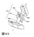
2.プレート
インプラントの側壁は、1つまたは複数のプレートを含んでもよい。いくつかの実施形態では、側壁のうちの1つまたはその一部が、インプラントの残りの部分と一体であるプレートに置換される。2. Plate The side wall of the implant may include one or more plates. In some embodiments, one or part of the side wall is replaced with a plate that is integral with the rest of the implant.
「プレート」という用語は、本明細書において用いられる場合、外側表面に位置付けられるかまたはインプラントの外側表面の一部もしくはすべてを形成するインプラントの一部を大略的に指す。プレートは、平坦なまたは丸みを帯びた表面であるものとすることができる。プレートは大略的に、1つまたは複数のコイルからは形成されない。 As used herein, the term "plate" broadly refers to a portion of an implant that is located on the lateral surface or that forms part or all of the lateral surface of the implant. The plate can be a flat or rounded surface. The plate is generally not formed from one or more coils.
2つ以上の外側壁を含む実施形態では、任意選択的に、プレートのうちの1つは、インプラントの壁のうちの1つを画定し、インプラントの2個の他の壁に接続される。いくつかの実施形態では、外側壁は、インプラントの前方端の前方プレートおよびインプラントの後方端の後方プレートを含む外周リングの形態である。 In embodiments involving two or more outer walls, optionally one of the plates defines one of the walls of the implant and is connected to two other walls of the implant. In some embodiments, the lateral wall is in the form of an outer ring that includes an anterior plate at the anterior end of the implant and a posterior plate at the posterior end of the implant.
プレートは、インプラントに存在する場合、1つまたは複数のコイルと交差し、側壁のうちの1つもしくは複数、または、側壁の一部を形成してもよい。 The plate, if present in the implant, may intersect one or more coils to form one or more of the side walls, or part of the side wall.
3.開スペース
本明細書において記載されるインプラントは、インプラントの中央、コイル間および/もしくはコイル内、ならびに/または、コイルと中央支持部分との間等における開スペースを含み、インプラントにおけるおよびインプラントを通した骨成長を促進する。開スペースの一部またはすべては、任意選択的に、患者の部位におけるインプラントの挿入前または挿入後に、骨移植片または骨移植片代用品で満たされ、骨成長を促進する。3. 3. Open Space The implants described herein include an open space in the center of the implant, between and / or within the coil, and / or between the coil and the central support, etc., in and through the implant. Promotes bone growth. Part or all of the open space is optionally filled with bone grafts or bone graft substitutes before or after implant insertion at the patient's site to promote bone growth.
任意の特定のインプラント内の開スペースの総体積は、インプラントの全体的な寸法、ならびに、コイル、中央支持体(存在する場合)、前方プレート、後方プレート等を含むインプラント内の個々の構成要素のサイズおよび寸法に依存する。空隙の体積は通常、インプラントの体積の約20%〜80%に及ぶ。任意選択的に、インプラントの空隙の体積は、インプラントの体積の少なくとも20%、25%、30%、35%、40%、45%、50%、55%、60%、65%、70%、75%または80%である。ALIFインプラント等の椎体間固定スペーサの場合に好ましくは、パーセント空隙体積は、インプラントの総体積の少なくとも約25%、より好ましくは少なくとも約40%、および、インプラントの総体積の最大でも80%であり、好ましくは、空隙の体積は、約25%〜75%、より好ましくは約40%〜75%に及ぶ。 The total volume of open space within any particular implant is the overall size of the implant, as well as the individual components within the implant, including the coil, central support (if any), anterior plate, posterior plate, etc. Depends on size and dimensions. The volume of the void typically ranges from about 20% to 80% of the volume of the implant. Optionally, the volume of the implant void is at least 20%, 25%, 30%, 35%, 40%, 45%, 50%, 55%, 60%, 65%, 70% of the implant volume. 75% or 80%. In the case of interbody fixation spacers such as ALIF implants, the percent void volume is preferably at least about 25%, more preferably at least about 40% of the total volume of the implant, and at most 80% of the total volume of the implant. Yes, preferably the volume of the voids ranges from about 25% to 75%, more preferably from about 40% to 75%.
4.インプラントの様々な用途
脊柱において使用されるインプラントは、脊柱内、通常は2つの椎体間に挿入するのに好適な全体的な寸法を有する。インプラントの形状および寸法は、インプラントが挿入される部位に依存する。たとえば、ALIFデバイスの場合、インプラントは通常、18mm以上、好ましくは約20mm〜約40mmの前後深さ、約24mm〜約46mm等の24mm以上の横幅、および、6mm〜60mmに及ぶ(その最高点における)高さを有する。インプラントを形成するのに使用されるコイルの好適な直径は通常、直径が少なくとも0.79mmである。4. Various Uses of Implants Implants used in the spinal column have overall dimensions suitable for insertion within the spinal column, usually between two vertebral bodies. The shape and dimensions of the implant depend on where the implant is inserted. For example, in the case of ALIF devices, implants typically range from 18 mm or more, preferably anterior-posterior depths of about 20 mm to about 40 mm, widths of 24 mm or more such as about 24 mm to about 46 mm, and 6 mm to 60 mm (at its highest point). ) Have a height. A suitable diameter of the coil used to form the implant is usually at least 0.79 mm in diameter.
i.閉ループのスタックから形成される壁によって囲まれる積み重ねられたコイルの列を有するインプラントの実施形態
いくつかの実施形態では、インプラントの内側部分は通常、積み重ねられたコイルの列で満たされる。積み重ねられたコイルのそれぞれの列において、コイルのすべては、単一の軸(z)に沿って位置合わせする。それぞれの列におけるコイル(またはコイルのセット)の数は、同じであってもよく、または異なっていてもよい。付加的に、インプラントの内部を形成する列のそれぞれにおけるコイル(またはコイルのセット)の数は、側壁を形成するように積み重ねられるコイル(またはコイルのセット)の数と同じであってもよい。複数の列の積み重ねられたコイルの上部および下側部分は、上側の外側表面および下側の外側表面をそれぞれ形成する。通常、複数の列の中央の列において、中央のコイル(コイルのセットまたはコイルの群)は、同じ列における他のコイルよりも大きい直径を有する(本明細書では「中央支持コイル」850と称される)。3Dプリントプロセスは、下から上にまたは上から下にインプラントを構築する(重なり合う層を構築するために支持構造を必要とするため)。i. Embodiments of an implant having a stack of coil rows surrounded by a wall formed from a closed-loop stack In some embodiments, the inner portion of the implant is usually filled with a stack of coil rows. In each row of stacked coils, all of the coils are aligned along a single axis (z). The number of coils (or sets of coils) in each row may be the same or different. Additionally, the number of coils (or sets of coils) in each of the rows forming the interior of the implant may be the same as the number of coils (or sets of coils) stacked to form the sidewalls. The upper and lower portions of the stacked coils in multiple rows form the upper outer surface and the lower outer surface, respectively. Typically, in the central row of multiple rows, the central coil (set of coils or group of coils) has a larger diameter than the other coils in the same row (referred to herein as "central support coil" 850). Will be). The 3D printing process builds implants from bottom to top or top to bottom (because it requires a support structure to build overlapping layers).
コイルのパッキング密度は、インプラントの用途に応じて変わる。 The packing density of the coil will vary depending on the implant application.
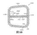
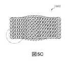
図5A〜図5Dにおいて示されているように、インプラント1000は、4個の側壁1100、1200、1300および1400ならびに内側部分1600を含む。 As shown in FIGS. 5A-5D, the
側壁は、複数の積み重ねられた閉ループコイルから形成される。たとえば、図5A〜図5Cにおいて示されているインプラントは、6列のセットの閉ループコイルを含み、この場合、コイルのそれぞれのセット800は、2個の合同コイル100および700を含む。 The side wall is formed from a plurality of stacked closed loop coils. For example, the implants shown in FIGS. 5A-5C include a set of 6 rows of closed loop coils, in which case each set of
積み重ねられたコイルの1つの列1700のみが、見やすくするために図5A〜図5Cにおいて示されているインプラントの内側部分1600において示されている。図面に示されているように、上側の外側表面1800および下側の外側表面(図示せず)は、コイルの列1700の上側部分および下側部分によって画定される。しかし、通常は、インプラントは、複数の列の積み重ねられたコイルを含み、この場合、列のそれぞれの上側部分は、完全な上側の外側表面を形成し、列のそれぞれの下側部分は、完全な下側の外側表面を形成する。 Only one row of 1700 of stacked coils is shown in the
側壁と同様に、コイルの列1700は好ましくは、コイルのセット6個のスタックを含み、この場合、コイルのそれぞれのセット900’および900’’は、2個の合同コイル100’および700’を含む。それぞれのコイルの端は、側壁1100または1300の内側部分1110および1310にそれぞれ取り付けられる。任意選択的に、コイルのセットを含むスタックの代わりに、スタックは、図3A〜図3Bおよび図4A〜図4Bにおいて示されているような単一のコイルもしくはコイルの群、または、コイルのそのようなセットおよび群の組み合わせもしくは変形を含んでもよい。 Like the sidewalls, the row of
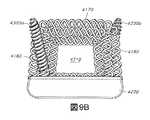
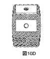
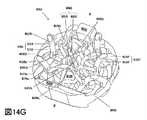
ii.複数の閉ループコイルおよび/または中断ループから形成されるインプラント
図7Aおよび図7B、図9A〜図9Dおよび図10A〜図10Dにおいて示されているような別の実施形態では、インプラントは、側壁を形成する積み重ねられたループ、ならびに、インプラントの内部とともにインプラントの上側表面および下側表面を形成する実質的に同心のループの形態等の、複数の閉ループコイルおよび/または中断ループを含む。ii. Implants Formed from Multiple Closed Loop Coil and / or Suspended Loops In another embodiment as shown in FIGS. 7A and 7B, FIGS. 9A-9D and 10A-10D, the implant forms a sidewall. Includes multiple closed-loop coils and / or interrupted loops, such as stacked loops that form the implant, as well as substantially concentric loop forms that form the upper and lower surfaces of the implant with the interior of the implant.
インプラントは、インプラントの用途に依存する任意の好適なサイズおよび形状を有することができる。インプラントは、複数の側壁、通常は少なくとも4個の側壁、任意選択的には5個以上の側壁、1つの上側表面および1つの下側表面を含む。閉ループコイルは通常、コイルのセットまたはコイルの群の形態の2つ以上のコイルを含む。好ましい実施形態では、閉ループコイルのそれぞれはコイルのセットである。インプラントは好ましくは、閉ループコイルの2つ以上のレベルを含み、この場合、それぞれのレベルは、少なくとも1つの、および好ましくは2つ以上の閉ループコイルを含む。好ましい実施形態では、それぞれのレベルは複数の同心の閉ループコイルを含み、この場合、最も外側の閉ループコイルは、最も大きい寸法(たとえば直径)を有し、インプラントの内部に向かって移動するそれぞれの隣接する閉ループコイルの寸法は、隣接する外側の閉ループコイルよりも小さい。 The implant can have any suitable size and shape depending on the application of the implant. The implant comprises a plurality of sidewalls, usually at least 4 sidewalls, optionally 5 or more sidewalls, one upper surface and one lower surface. Closed-loop coils typically include two or more coils in the form of a set of coils or a group of coils. In a preferred embodiment, each of the closed loop coils is a set of coils. The implant preferably comprises two or more levels of closed-loop coils, in which case each level comprises at least one, and preferably two or more closed-loop coils. In a preferred embodiment, each level comprises a plurality of concentric closed-loop coils, in which case the outermost closed-loop coil has the largest dimension (eg, diameter) and is adjacent to each moving towards the interior of the implant. The size of the closed loop coil is smaller than that of the adjacent outer closed loop coil.
図7Aおよび図7Bにおいて示されているように、インプラント2000は、4個の側壁2100、2200、2300および2400、1つの上側表面2600ならびに1つの下側表面2700を含む。 As shown in FIGS. 7A and 7B, the
側壁は、複数の積み重ねられた閉ループコイルの外側表面によって画定される。たとえば、図7Aおよび図7Bにおいて示されているインプラントはコイルの3個のレベルを含み、この場合、それぞれのレベルはコイルのセットを3個含み、それぞれのセットは2個の合同コイルを含む。 The sidewalls are defined by the outer surface of a plurality of stacked closed loop coils. For example, the implants shown in FIGS. 7A and 7B contain three levels of coils, where each level contains three sets of coils, each set containing two congruent coils.
a.閉ループの形態のコイルのセット
連続的な閉ループの形態のコイルの単一のセット800が、見やすくするために図6A〜図6Dにおいて示されている。図6A〜図6Dにおいて示されているように、コイルのそれぞれのセット800は、2個の合同コイル100および700を含む。それぞれのセットにおけるコイルの数は、単に例示目的であり、当業者は、それぞれのセットが同じ数の合同コイルまたは異なる数の合同コイルを有することができることを理解するであろう。付加的に、それぞれのセットにおける合同コイルの数は、それぞれのセットにおいて少なくとも1個、2個、3個、4個、5個、6個、7個、8個、9個または10個以上の合同コイル等、必要に応じて変えることができる。それぞれのセットにおける15個以上、20個以上またはさらにより多い数等の、合同コイルの他の量も想定される。a. A set of coils in the form of a closed loop A
単一の閉ループの湾曲が、側面図(図6Cおよび図6D)において分かる。いくつかの実施形態では、コイルのそれぞれのセットは、インプラントの上側表面または下側表面に隣接することになる体内の表面の凸状部または凹状部に大略的に対応するプロファイルを有してもよい。たとえば、図6Cおよび図6Dにおいて示されているように、閉ループは、凸状面または凹状面のプロファイルを有してもよい。凸状面の形状は、脊椎固定インプラントに特に有用である。 The curvature of a single closed loop can be seen in the side views (FIGS. 6C and 6D). In some embodiments, each set of coils may have a profile that roughly corresponds to the convex or concave portion of the surface of the body that will be adjacent to the upper or lower surface of the implant. Good. For example, as shown in FIGS. 6C and 6D, the closed loop may have a convex or concave profile. The convex surface shape is particularly useful for spinal fixation implants.
いくつかの実施形態では、上側表面または下側表面のみが、体内の隣接する表面の凸状部または凹状部に対応するプロファイルを有する。たとえば、インプラントの上側表面または下側表面を形成する、レベルにおけるコイルの1つまたは複数のセットは、インプラントの上側表面が通常のコイルよりも平坦であり、椎体の端等の隣接する凹状面に大略的に対応するように、変更された形状を有してもよい。 In some embodiments, only the upper or lower surface has a profile that corresponds to the convex or concave portion of the adjacent surface in the body. For example, one or more sets of coils at the level that form the upper or lower surface of the implant have the upper surface of the implant flatter than a normal coil and adjacent concave surfaces such as the ends of the vertebral body. May have a modified shape to roughly correspond to.
b.同心のコイルのレベル
インプラントは、任意の好適な数のレベルを有してもよく、それぞれのレベルは、任意の好適な数のコイルの同心のループを含んでもよい。レベルの好適な数は、ループの半径およびインプラントの全体的なサイズに応じて、2個〜100個またはそれ以上に及ぶ。通常、脊椎インプラントの場合、レベルの数は、2個〜約40個、好ましくは2個〜30個、より好ましくは2個〜約10個、好ましくは2個〜6個に及ぶ。b. Levels of Concentric Coil Implants may have any suitable number of levels, and each level may include concentric loops of any suitable number of coils. A suitable number of levels can range from 2 to 100 or more, depending on the radius of the loop and the overall size of the implant. Generally, for spinal implants, the number of levels ranges from 2 to about 40, preferably 2 to 30, more preferably 2 to about 10, preferably 2 to 6.
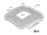
同心のコイル(またはコイルの同心のセット)の1つのレベル2800のみが、見やすくするために図8A〜図8Dにおいて示されている。これらの図において示されているように、レベルは、コイルのセット3個、2810、2820および2830、から形成され、この場合、コイルのそれぞれのセットは2個の合同コイル、たとえばセット2810における2812および2814を含む。それぞれのレベルにおけるコイルのセットの数は、単に例示目的であり、当業者は、それぞれのレベルが同じ数の同心のコイルまたは異なる数の同心のコイルを有することができることを理解するであろう。付加的に、それぞれのレベルにおける同心のコイルの数は、必要に応じて変えることができる。たとえば、それぞれのレベルは、少なくとも1個、2個、3個、4個、5個、6個、7個、8個、9個または10個以上の同心のコイルを含むことができる。それぞれのレベルにおける15個以上、20個以上またはより多くの数等の、同心のコイルの他の量も想定される。 Only one
上側の外側表面2850および下側の外側表面(図示せず)は、コイルのレベル2800の上側部分および下側部分によって画定される。 The upper
所与のレベル内または隣接するレベルにおけるコイルの隣接するセットにおけるコイルは、一定の間隔で、すなわち、コイル2810の回転内で同じ角度で、交差領域において互いに交差する。 The coils in an adjacent set of coils within a given level or at adjacent levels intersect each other in the intersection region at regular intervals, i.e. at the same angle within the rotation of the
図8Aおよび図8Cにおいて示されているように、コイルの外側のセット2810におけるコイル2812および2814は、交差領域2826a、2826bおよび2826cにおいて、コイルの隣接するセット2820におけるコイル2822および2824と一定の間隔で交差する。交差領域は、それぞれの接続コイルに対して同じ相対的な位置に位置付けられる。たとえば、接続コイル2812および2822は、2812が0°位置にあり、2822が180°位置にあるときに、交差領域において接続する。同様に、接続コイル2814および2824は、2814が0°位置にあり、2824が180°位置にあるときに、交差領域において接続する。 As shown in FIGS. 8A and 8C, the
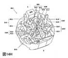
c.両凸インプラント
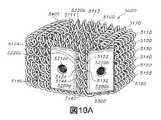
通常、インプラントは、同心のコイルの複数のレベルを含み、内側のレベルそれぞれの上側部分は、上記で説明したように、規則的な交差領域においてコイルの隣接するレベルの下側部分と交差する。図7Aおよび図7Bにおいて示されているように、インプラントは、同心の閉ループの3個のレベル2800、2900および3000を含む。インプラントにおけるレベルの数は、単に例示目的であり、当業者は、それぞれのインプラントが、インプラントのサイズおよびインプラントにおけるコイルのサイズに応じて、異なる数のレベルを有することができることを理解するであろう。たとえば、インプラントにおけるレベルの数は、10個以上、15個以上、20個以上または最高で40個のレベル等の、2個以上であるものとすることができる。いくつかの実施形態では、インプラントは、最高で100個または最高で1000個等の、より多くの量のレベルを含んでもよい。c. Biconvex implants Implants typically contain multiple levels of concentric coils, with the upper part of each inner level being the lower part of the adjacent level of the coil in a regular intersecting region, as described above. Cross. As shown in FIGS. 7A and 7B, the implant comprises three
それぞれのレベルにおける外側の閉ループ(2810、2910および3010)を見ると、コイルの外側のセット2910は、隣接するレベルにおけるコイルの外側のセット2810および3010と一定の間隔で接続する2個のコイル2912および2914を含む。たとえば、コイルの外側のセット3010におけるコイル3012および3014のそれぞれは、コイルに沿う同じ相対的な位置に一定の間隔で位置付けられる交差領域3026a、3026bおよび3026cにおいて、コイルの外側のセット2910におけるコイルのうちの1つに接続する。同様に、コイルの外側のセット2810におけるコイルのそれぞれは、コイルに沿う同じ相対的な位置に一定の間隔で位置付けられる交差領域2926a、2926b、2926cおよび2926dにおいて、コイルの外側のセット2910におけるコイルのうちの1つに接続する。 Looking at the outer closed loops (2810, 2910 and 3010) at each level, the
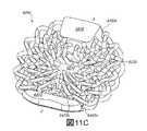
iii.複数のコイル状円弧から形成されるインプラント
図11A〜図11Eにおいて示されているような別の実施形態では、インプラントは、側壁と、インプラントの内部とともにインプラントの上側表面および下側表面を形成する実質的に同心のコイル状円弧とを形成する積み重ねられたコイル状円弧の形態等の、複数のコイル状円弧を含む。iii. Implants Formed from Multiple Coiled Arcs In another embodiment, as shown in FIGS. 11A-11E, the implant is a parenchyma that forms the upper and lower surfaces of the implant along with the sidewalls and interior of the implant. Includes a plurality of coiled arcs, such as in the form of stacked coiled arcs that form concentric coiled arcs.
コイル状円弧の代替として、任意の幾何学的形状のコイル状セグメントをインプラントにおいて使用してもよい。 As an alternative to the coiled arc, coiled segments of any geometry may be used in the implant.
インプラントは、インプラントの用途に依存する任意の好適なサイズおよび形状を有することができる。インプラントは、複数の側壁、通常は少なくとも4個の側壁、任意選択的には5個以上の側壁、1つの上側表面および1つの下側表面を含む。コイル状円弧は通常、コイルのセットまたはコイルの群の形態の2つ以上のコイルを含む。好ましい実施形態では、コイル状円弧のそれぞれはコイルのセットである。インプラントは好ましくは、コイル状円弧の2つ以上のレベルを含み、この場合、それぞれのレベルは、少なくとも1つの、および好ましくは2つ以上のコイル状円弧を含む。好ましい実施形態では、それぞれのレベルは複数の同心のコイル状円弧を含み、この場合、外側コイル状円弧は、最も大きい寸法(たとえば半径)を有し、内側コイル状円弧の寸法は最小である。同様に、それぞれの中間コイル状円弧は、内側コイル状円弧よりも大きい半径を有し、中間コイル状円弧の半径は、インプラントの中央に対して外方に移動するにつれて増大する。 The implant can have any suitable size and shape depending on the application of the implant. The implant comprises a plurality of sidewalls, usually at least 4 sidewalls, optionally 5 or more sidewalls, one upper surface and one lower surface. A coiled arc usually includes two or more coils in the form of a set of coils or a group of coils. In a preferred embodiment, each of the coiled arcs is a set of coils. The implant preferably comprises two or more levels of coiled arcs, in which case each level comprises at least one, and preferably two or more levels of coiled arcs. In a preferred embodiment, each level comprises a plurality of concentric coiled arcs, in which case the outer coiled arc has the largest dimension (eg radius) and the inner coiled arc has the smallest dimension. Similarly, each intermediate coiled arc has a larger radius than the inner coiled arc, and the radius of the intermediate coiled arc increases as it moves outward with respect to the center of the implant.
いくつかの実施形態では、インプラントは、少なくとも2個の合同コイル、ならびに、コイル間および/またはコイル内の開口を含む複数のコイルまたはコイルのセットを含み、この場合、インプラントは、外側の側壁、上側表面および下側表面ならびに内側部分を含み、この場合、内側部分は外側の側壁内にあり、この場合、外側の側壁、上側表面および下側表面は、複数のコイルまたはコイルのセットから形成され、この場合、側壁は、複数のコイルまたはコイルのセットのスタックから形成され、この場合、コイルまたはコイルのセットは、コイル状円弧の形態である。 In some embodiments, the implant comprises at least two congruent coils and a plurality of coils or a set of coils including openings between and / or in the coils, in which case the implant is an outer side wall. Including the upper and lower surfaces as well as the inner portion, in this case the inner portion is within the outer sidewall, in which case the outer sidewall, upper surface and lower surface are formed from a plurality of coils or a set of coils. In this case, the sidewall is formed from a stack of multiple coils or a set of coils, in which case the coil or set of coils is in the form of a coiled arc.
任意選択的に、インプラントの内側部分は、積み重ねられたコイルまたは積み重ねられたコイルのセットの複数の列を含む。任意選択的に、それぞれの列におけるコイルまたはコイルのセットの数は、外側の側壁を形成するコイルのスタックにおけるコイルまたはコイルのセットの数と同じである。 Optionally, the inner portion of the implant comprises multiple rows of stacked coils or a set of stacked coils. Optionally, the number of coils or sets of coils in each row is the same as the number of coils or sets of coils in the stack of coils forming the outer sidewall.
インプラントは1つまたは複数のプレートをさらに含んでもよく、この場合、1つまたは複数のプレートはインプラントの壁と一体である。任意選択的に、プレートのうちの1つは、インプラントの壁のうちの1つとして働き、その側部がインプラントの他の壁に接続される。 The implant may further include one or more plates, in which case the one or more plates are integral with the wall of the implant. Optionally, one of the plates acts as one of the walls of the implant and its sides are connected to the other wall of the implant.
いくつかの実施形態では、コイルまたはコイルのセットのうちの1つまたは複数は、コイルの長さにわたって変わる直径(D)を有する。任意選択的に、直径(D)は、インプラントの前方端において最も大きく、後方端において最も小さい。他の実施形態では、直径(D)は、インプラントの中央において最も大きく、インプラントの中央からインプラントの前方端および後方端に向かって移動するにつれて縮小する。いくつかの好ましい実施形態では、インプラントは、前方経路腰椎椎体間固定(ALIF)デバイスである。 In some embodiments, one or more of the coils or sets of coils have a diameter (D) that varies over the length of the coil. Optionally, the diameter (D) is largest at the anterior end of the implant and smallest at the posterior end. In another embodiment, the diameter (D) is largest in the center of the implant and shrinks as it moves from the center of the implant towards the anterior and posterior ends of the implant. In some preferred embodiments, the implant is an anterior route lumbar interbody fusion (ALIF) device.
図11A〜図11Eにおいて示されているように、インプラント6000は、コイル状円弧によって画定される側壁ならびに上側表面および下側表面を含み、コイル状円弧の外側のセット6100、6100’は、インプラントの正中面Mを対称面として、互いに反対に対称である。インプラントは、1つのレベル6710がインプラントの横断面Tに沿って他のレベル6720の反対に対称であるように、横断面Tにおける別の対称面を有する。 As shown in FIGS. 11A-11E,
側壁は、コイル状円弧の複数のセットの外側表面によって画定される。たとえば、図11A〜図11Eにおいて示されているインプラントは2個のレベル6710および6720を含み、この場合、それぞれのレベルはコイル状円弧のセットを6個含み、正中面Mの一方の側の1つのレベルにおける3個のセット、および、正中面Mの他方の側の他の3個のセットを有する。 The sidewalls are defined by the outer surface of a plurality of sets of coiled arcs. For example, the implants shown in FIGS. 11A-11E contain two
a.コイル状円弧のセット
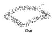
図11A〜図11Eにおいて示されているように、コイルのそれぞれのセット6100は、2個の合同コイル6110および6120を含む。それぞれのセットにおけるコイルの数は、単に例示目的であり、当業者は、それぞれのセットが同じ数の合同コイルまたは異なる数の合同コイルを有することができることを理解するであろう。それぞれのセットにおける合同コイルの数は、それぞれのセットにおける少なくとも1個、2個、3個、4個、5個、6個、7個、8個、9個または10個以上の合同コイル等、必要に応じて変えることができる。それぞれのセットにおける15個以上、20個以上またはより多くの数等の、合同コイルの他の量も想定される。a. A set of coiled arcs As shown in FIGS. 11A-11E, each set of
いくつかの実施形態では、コイル状円弧のそれぞれのセットは、インプラントの上側表面または下側表面に隣接することになる体内の表面の凸状部または凹状部に大略的に対応するプロファイルを有してもよい。たとえば、図11Eにおいて示されているように、湾曲した円弧は、典型的なALIFインプラントのプロファイルを有してもよい。この形状は、脊椎固定インプラントに特に有用である。 In some embodiments, each set of coiled arcs has a profile that roughly corresponds to the convex or concave portion of the surface of the body that will be adjacent to the upper or lower surface of the implant. You may. For example, as shown in FIG. 11E, the curved arc may have a typical ALIF implant profile. This shape is particularly useful for spinal fixation implants.
いくつかの実施形態では、上側表面または下側表面のみが、体内の隣接する表面の凸状部または凹状部に対応するプロファイルを有する。たとえば、インプラントの上側表面または下側表面を形成するレベルにおけるコイルの1つまたは複数のセットは、インプラントの上側表面が通常のコイルよりも平坦であるかまたはより湾曲しているように、変更された形状を有してもよい。 In some embodiments, only the upper or lower surface has a profile that corresponds to the convex or concave portion of the adjacent surface in the body. For example, one or more sets of coils at the level forming the upper or lower surface of the implant are modified so that the upper surface of the implant is flatter or more curved than a normal coil. May have a different shape.
b.コイル状円弧のレベル
インプラントは、任意の好適な数のレベルを有してもよく、それぞれのレベルは、任意の好適な数の同心のコイル状円弧を含んでもよい。たとえば、レベルの数は、円弧の半径およびインプラントの全体的なサイズに応じて、2個〜1000個またはそれ以上に及んでもよい。脊椎インプラントの場合に通常は、レベルの数は、2個〜約30個、好ましくは2個〜20個または2個〜10個に及ぶ。b. Levels of coiled arcs Implants may have any suitable number of levels, and each level may include any suitable number of concentric coiled arcs. For example, the number of levels may range from 2 to 1000 or more, depending on the radius of the arc and the overall size of the implant. In the case of spinal implants, the number of levels typically ranges from 2 to about 30, preferably 2 to 20 or 2 to 10.
これらの図において示されているように、レベル6710は、コイル状円弧のセット3個、6100、6120および6130、から形成され、この場合、コイル状円弧のそれぞれのセットは、2個の合同コイル、たとえばセット6100における6110および6120を含む。それぞれのレベルにおけるコイル状円弧のセットの数は、単に例示目的であり、当業者は、それぞれのレベルが同じ数の同心のコイル状円弧または異なる数の同心のコイル状円弧を有することができることを理解するであろう。付加的に、それぞれのレベルにおける同心のコイル状円弧の数は、必要に応じて変えることができる。たとえば、それぞれのレベルは、少なくとも1個、2個、3個、4個、5個、6個、7個、8個、9個または10個以上の同心のコイル状円弧を含むことができる。それぞれのレベルにおける15個以上、20個以上またはより多くの数等の、同心のコイル状円弧の他の量も想定される。 As shown in these figures,
上側の外側表面6510および下側の外側表面6530は、コイル状円弧のレベル6710および6720の、合同コイル6110、6120、6210、6220、6310および6320の上側表面6112a、6112b等、6122a、6122b等、6212a、6212b等、6222a、6222b等、ならびに、合同コイル6110’’、6120’’、6210’’、6220’’、6310’’および6320’’の下側表面6112a’’、6112b’’等、6122a’’、6122b’’等、6212a’’、6212b’’等、6222a’’、6222b’’等、および、6312a’’、6312b’’等、6322a’’、6322b’’によって画定される。 The upper
所与のレベル内または隣接するレベルにおけるコイル状円弧の隣接するセットにおけるコイルは、交差領域において互いに交差する。図11Eにおいて示されているように、第1のレベル6710におけるコイル状円弧6100のコイル6110および6120は、交差領域6520a、6520bにおいて、第2のレベル6720におけるコイル状円弧6100’’のコイル6110’’および6120’’と交差する。また、コイル状円弧6100のコイル6110および6120は、交差領域6250a、6250b等において、同じレベル6710におけるコイル状円弧6200のコイル6210および6220と交差する。 The coils in an adjacent set of coiled arcs within a given level or at adjacent levels intersect each other in the intersecting region. As shown in FIG. 11E, the
c.椎間インプラント
図11A〜図11Eにおいて示されているような一実施形態では、インプラントは、それぞれのレベルにおける複数のコイル状円弧、すなわち、外側コイル状円弧6100、6100’、中間コイル状円弧6200、6200’および内側コイル状円弧6300、6300’、を含む。コイル状円弧は2個の合同コイルから形成される。たとえば、外側コイル状円弧6100は、2個の合同コイル6110および6120から形成され、中間コイル状円弧6200は、2個の合同コイル6210および6220から形成され、内側コイル状円弧6300は、2個の合同コイル6310および6320から形成される。c. Intervertebral Implants In one embodiment, as shown in FIGS. 11A-11E, the implant has a plurality of coiled arcs at each level, namely lateral
インプラントが正中面Mによって分けられた場合のレベル6710の一方の半体を参照すると、半体6910は、同心の配置で配置される、外側コイル状円弧6100、中間コイル状円弧6200および内側コイル状円弧6300から形成される3個の交差するコイル状円弧を含む。レベルの第2の半体6920は、第1の半体6910の鏡像である。ともに、双方の半体6910および6920の相互接続するコイル状円弧は、レベル6710を形成する。 With reference to one half of the
図11A〜図11Eにおいて示されているインプラントは、対向する同心のコイル状円弧の2個のレベル、すなわち、上側レベル6710および下側レベル6720を含む。まとめて、インプラントのレベルは6700である。下側レベル6720は、インプラントの横断面Tに沿う上側レベル6710の鏡像である。この実施形態では、インプラントは、正中面Mおよび横断面Tに沿って対称である。 The implants shown in FIGS. 11A-11E include two levels of opposing concentric coiled arcs, namely the
インプラントの上側表面および下側表面は、インプラントが患者の体内にあるときに隣接する椎骨終板の形状に一致する、すなわち篏合する、任意の形状であるものとすることができる。たとえば、上側表面および/または下側表面は、形状が凸状、凹状または両凸等であるものとすることができる。これは、椎間板腔におけるインプラントの確実で密なフィットを提供する。この実施形態では、合同コイル6110、6120、6210、6220、6310および6320は、平坦化された上側表面6112a、6112b等、6122a、6122b等、6212a、6212b等、6222a、6222b等を含み、インプラントの上側表面6510をまとめて形成する。同様に、下側レベル6720では、外側コイル状円弧6100’’を形成する合同コイル6110’’、6120’’、中間コイル状円弧6200’’を形成する合同コイル6210’’、6220’’、および、内側コイル状円弧(図示せず)の2個の合同コイルは、平坦化された下側表面6112a’’、6122a’’等を含む。下側レベル6720のコイル状円弧におけるコイルの平坦化された表面は、インプラントの下側表面6530をまとめて形成する。 The upper and lower surfaces of the implant can be of any shape that matches, or aligns with, the shape of the adjacent vertebral endplates when the implant is inside the patient's body. For example, the upper surface and / or the lower surface may be convex, concave, biconvex, or the like in shape. This provides a secure and tight fit of the implant in the disc space. In this embodiment, the
インプラントは、前方プレート6600および後方プレート6400も含む。コイルは、それらの接続端を介してこれらのプレートの双方に接続する。たとえば、コイル6110は、接続端6111がプレート6400の内側に接続し、コイル6120は、接続端6121がプレート6400の内側に接続する。前方プレート6600は、挿入器具、骨移植片展開器具または隣接する骨生体構造への別個の固定具を受け入れるように構成されている穴6620を含む。インプラントの前方Aから見て、外側コイル状円弧6100、6100’、中間コイル状円弧6200、6200’、および、内側コイル状円弧6300、6300’は、前方プレート6600から後方プレートに向かって湾曲して延びる。インプラントの後方Pにおいて、外側コイル状円弧6100の合同コイル6110および6120は、接続端6450a、6450b等において後方プレート6400に合流する。インプラントの後方Pにおいて、中間コイル状円弧6200の合同コイル6210および6220、ならびに、内側コイル状円弧6300の合同コイル6310および6320は、接続端6420a、6420b、6420cにおいて、正中面Mに沿ってそれらのそれぞれの鏡像の合同コイルに合流する。コイルが前方プレート6600から後方プレート6400に向かって延びるにつれて、コイルの直径(D)は低減し、インプラントの後方Pにおいて最小の直径に達する。 Implants also include
図11A〜図11Cにおいて示されているように、インプラントは、インプラントの中央に大きい開スペース6830を含んでもよい。大きい開スペース6830の一部またはすべては、任意選択的に骨移植片または骨移植片代用品で満たされ、骨成長を促進する。インプラント6000は、外側コイル状円弧6100の内部および周りに形成される、開スペース6820a、6820b等、まとめて6820、および、開スペース6810a、6810b等、まとめて6810も含む。開スペース6820、6810の任意の部分またはすべてを、任意選択的に骨移植片または骨移植片代用品で満たし、骨成長を促進してもよい。 As shown in FIGS. 11A-11C, the implant may include a large
iv.複数の中断ループから形成されるインプラント
図12A〜図12Eにおいて示されているような別の実施形態では、インプラントは、側壁を形成する積み重ねられた中断ループ、ならびに、インプラントの内部とともにインプラントの上側表面および下側表面を形成する実質的に同心のループの形態等の、複数の中断ループを含む。任意選択的に、インプラントは、通常は内側コイルまたはコイルの内側のセットもしくは群として、任意選択的には1つまたは複数の中間のコイル、または、コイルの中間のセットもしくは群としても、1つまたは複数の閉ループコイルも含む。iv. Implants Formed from Multiple Suspension Loops In another embodiment, as shown in FIGS. 12A-12E, the implant has a stacked suspension loop forming a side wall, as well as the upper surface of the implant along with the interior of the implant. And includes multiple interruption loops, such as the form of substantially concentric loops forming the underside surface. Optionally, the implant is usually an inner coil or an inner set or group of coils, optionally one or more intermediate coils, or even an intermediate set or group of coils. Or it also includes a plurality of closed loop coils.
インプラントは、インプラントの用途に依存する、任意の好適なサイズおよび形状を有することができる。インプラントは、複数の側壁、通常は少なくとも4個の側壁、任意選択的には5個以上の側壁、1つの上側表面および1つの下側表面を含む。中断ループは通常、コイルのセットまたはコイルの群の形態の2つ以上のコイルを含む。好ましい実施形態では、中断ループのそれぞれはコイルのセットである。 The implant can have any suitable size and shape, depending on the application of the implant. The implant comprises a plurality of sidewalls, usually at least 4 sidewalls, optionally 5 or more sidewalls, one upper surface and one lower surface. The break loop usually includes two or more coils in the form of a set of coils or a group of coils. In a preferred embodiment, each of the interruption loops is a set of coils.
インプラントは好ましくは、コイルの2つ以上のレベルを含み、この場合、それぞれのレベルは、少なくとも1つの、および、好ましくは2つ以上の中断ループを含む。好ましい実施形態では、それぞれのレベルは複数の同心の中断ループを含み、この場合、外側のループは最大の寸法(たとえば直径)を有し、内側のループは最小の寸法を有する。任意の内側のループは、存在する場合、内側のループよりも大きい直径を有するが、外側のループよりも小さい直径を有し、直径は、ループがインプラントの内部に向かって移動するにつれて縮小する。 The implant preferably comprises two or more levels of coil, where each level comprises at least one and preferably two or more interruption loops. In a preferred embodiment, each level comprises a plurality of concentric break loops, in which case the outer loop has the largest dimension (eg diameter) and the inner loop has the smallest dimension. Any inner loop, if present, has a larger diameter than the inner loop, but a smaller diameter than the outer loop, and the diameter shrinks as the loop moves toward the inside of the implant.
図12A〜図12Eにおいて示されているように、インプラント7000は、ケージと一体化されているとともに、患者へのケージの挿入を容易にするように構成されている前方プレート7600、および、通常は丸みを帯びた端を有する楔の形状の後方プレート7400を含む。これらの図において、インプラントは、中断ループの同心のセットの2個のレベル(7710および7720)を含み、この場合、それぞれのレベルは、中断ループのセット2個(上側レベル7710における7810および7820、ならびに、下側レベル7720における7810’および7820’)を含み、それぞれのセットは、2個の合同コイル(中断ループの外側のセット7810をまとめて形成する7812および7814、ならびに、中断ループの内側のセット7820をまとめて形成する7822および7824)、上側表面7850ならびに下側表面7830を含む。インプラントは、前方端7200および後方端7300を有する。インプラントは、前方端7200および後方端7300において異なる高さを有してもよい。通常、インプラントの形状は、コイルの直径Dにおける変化とともに変化する。 As shown in FIGS. 12A-12E, the
a.閉ループおよび/または中断ループの形態のコイルのセット
連続的な閉ループの形態の、まとめてレベル7710を形成するコイルのセット2個、7810および7820が、見やすくするために図13Aおよび図13Bにおいて示されている。図13Aおよび図13Bにおいて示されているように、コイルのセット7810は、2個の合同コイル7812および7814を含み、コイルのセット7820は、2個の合同コイル7822および7824を含む。それぞれのセットにおけるコイルの数は、単に例示目的であり、当業者は、それぞれのセットが同じ数の合同コイルまたは異なる数の合同コイルを有することができることを理解するであろう。付加的に、それぞれのセットにおける合同コイルの数は、それぞれのセットにおいて少なくとも1個、2個、3個、4個、5個、6個、7個、8個、9個または10個以上の合同コイル等、必要に応じて変えることができる。それぞれのセットにおける15個以上、20個以上またはさらにより多い数等の、合同コイルの他の量も想定される。a. A set of coils in the form of a closed loop and / or a break loop Two sets of coils, 7810 and 7820, in the form of a continuous closed loop, together forming
単一の閉ループの湾曲が、側面図(図13B)において分かる。いくつかの実施形態では、コイルのそれぞれのセットは、インプラントの上側表面または下側表面に隣接することになる体内の表面の凸状部または凹状部に大略的に対応するプロファイルを有してもよい。この実施例では、コイルのセットは、可変の直径Dを有するコイルから形成され、それによって、インプラントの前方端7200’におけるコイルは、インプラントの後方端7300’におけるコイルよりも大きい直径を有し、インプラントは、前方端から後方端に直径がテーパー状になる。最大の直径Dは、最大で13mm、最大で9mm、最大で8mm、最大で7mm、最大で6mm、好ましくは5mmであってもよく、所与のコイルにおける最小の直径(D)は、コイルの最大の直径よりも小さく、好ましくは0.7mm〜4mm、または、約1mm、より好ましくは2mmに及ぶ。たとえば、図12Eにおいて示されているように、インプラントは楔の形状を有してもよい。この形状は、脊椎固定インプラントに特に有用である。 The curvature of a single closed loop can be seen in the side view (FIG. 13B). In some embodiments, each set of coils may have a profile that roughly corresponds to the convex or concave portion of the surface of the body that will be adjacent to the upper or lower surface of the implant. Good. In this embodiment, the set of coils is formed from coils with a variable diameter D, whereby the coil at the anterior end 7200'of the implant has a larger diameter than the coil at the posterior end 7300' of the implant. Implants taper in diameter from the anterior end to the posterior end. The maximum diameter D may be up to 13 mm, up to 9 mm, up to 8 mm, up to 7 mm, up to 6 mm, preferably 5 mm, and the minimum diameter (D) in a given coil is that of the coil. It is smaller than the maximum diameter, preferably 0.7 mm to 4 mm, or about 1 mm, more preferably 2 mm. For example, as shown in FIG. 12E, the implant may have a wedge shape. This shape is particularly useful for spinal fixation implants.
いくつかの実施形態では、インプラントの上側表面または下側表面は、体内の隣接する表面の凸状部または凹状部に対応するプロファイルを有する。たとえば、インプラントの上側表面または下側表面におけるコイルの1つまたは複数のセットは、インプラントの上側表面が通常のコイルよりも平坦であり、椎体の端等の隣接する凹状面に大略的に対応するように、変更された形状を有してもよい。図12A〜図12Eにおいて、これは、インプラント7000の上側表面7850および下側表面7830によって実証されている。 In some embodiments, the upper or lower surface of the implant has a profile that corresponds to the convex or concave portion of the adjacent surface within the body. For example, one or more sets of coils on the upper or lower surface of the implant have the upper surface of the implant flatter than a normal coil and roughly correspond to adjacent concave surfaces such as the ends of the vertebral body. It may have a modified shape so that it does. In FIGS. 12A-12E, this is demonstrated by the
b.同心のコイルのレベル
インプラントは、任意の好適な数のレベルを有してもよく、それぞれのレベルは、任意の好適な数のコイルの同心のループを含んでもよい。レベルの好適な数は、ループの半径およびインプラントの全体的なサイズに応じて、2個〜1000個またはそれ以上に及ぶ。脊椎インプラントの場合に通常は、レベルの数は、2個〜約30個、好ましくは2個〜20個または2個〜10個に及ぶ。b. Levels of Concentric Coil Implants may have any suitable number of levels, and each level may include concentric loops of any suitable number of coils. A suitable number of levels can range from 2 to 1000 or more, depending on the radius of the loop and the overall size of the implant. In the case of spinal implants, the number of levels typically ranges from 2 to about 30, preferably 2 to 20 or 2 to 10.
同心のコイル(またはコイルの同心のセット)の1つのレベル7800のみが、見やすくするために図13Aおよび図13Bにおいて示されている。これらの図において示されているように、レベルは、コイルのセット2個、7810および7820から形成され、この場合、コイルのそれぞれのセットは、2個の合同コイル、たとえば、第1のセット7810におけるコイル7812および7814、ならびに、第2のセット7820におけるコイル7822および7824を含む。それぞれのレベルにおけるコイルのセットの数は、単に例示目的であり、当業者は、それぞれのレベルが同じ数の同心のコイルまたは異なる数の同心のコイルを有することができることを理解するであろう。それぞれのレベルにおける同心のコイルの数は、必要に応じて変えることができる。たとえば、それぞれのレベルは、少なくとも1個、2個、3個、4個、5個、6個、7個、8個、9個または10個以上の同心のコイルを含むことができる。それぞれのレベルにおける15個以上、20個以上またはより多くの数等の、同心のコイルの他の量も想定される。 Only one
上側表面7850および下側表面7840は、コイルのレベル7800の上側部分および下側部分によって画定される。 The
所与のレベル内または隣接するレベルにおけるコイルの隣接するセットにおけるコイルは、交差領域において互いに交差する。任意選択的に、交差領域は、一定の間隔で、すなわち、コイル7810の回転内で同じ角度で離間される。図12Aおよび図13Aにおいて示されているように、コイルの外側のセット7810におけるコイル7812および7814は、複数の交差領域7826a、7826bおよび7826cにおいて、コイルの隣接する内側のセット7820におけるコイル7822および7824と一定の間隔で交差する。 The coils in an adjacent set of coils within a given level or at adjacent levels intersect each other in the intersecting region. Optionally, the intersecting regions are spaced at regular intervals, i.e., at the same angle within the rotation of the
c.コイルの閉ループのセット、1つまたは複数のプレートによって中断ループの外側のセットから形成されるインプラント
通常、インプラントは、同心のコイルの複数のレベルを含み、内側のレベルのそれぞれの上側部分は、上記で説明したように、一定の交差領域においてコイルの隣接するレベルの下側部分と交差する。図12A〜図12Eにおいて示されているように、インプラントは、同心のループの2個のレベル7710および7720を含む。インプラントにおけるレベルの数は、単に例示目的であり、当業者は、インプラントに、異なる数のレベルを設けることができることを理解するであろう。たとえば、インプラントにおけるレベルの数は、10個以上、15個以上、20個以上または最高で100個もしくは最高で1000個のレベル等の、2個以上であるものとすることができる。c. Implants formed from a set of closed loops of coils and an outer set of interrupted loops by one or more plates Usually an implant contains multiple levels of concentric coils, each upper portion of the inner level described above. As described in, it intersects the lower part of the adjacent level of the coil in a certain intersection area. As shown in FIGS. 12A-12E, the implant comprises two
図12A〜図12Eにおいて示されているインプラントでは、上側レベル7710は、横断面Tを中心に下側レベル7720と対称である。 In the implants shown in FIGS. 12A-12E, the
上側レベル7710におけるコイルの外側のセット7810は、2個の合同コイル7812および7814を含み、同様に、下側レベル7720におけるコイルの外側のセット7810’は、2個の合同コイル7812’および7814’を含む。上側レベル7710におけるコイルの外側のセット7810のコイル7812および7814は、隣接するレベルにおけるコイルの外側のセット7810’のコイル7812’および7814’に一定の間隔で接続する。たとえば、コイルの外側のセット7810におけるコイル7812および7814は、それぞれのコイルに沿って一定の間隔で同じ相対的な位置に位置付けられる交差領域7520a、7520bおよび7520cにおいて、コイルの外側のセット7810’の2個のコイル7812’および7814’に接続する。 The
同様の交差領域が、上側レベル7710におけるコイルの内側のセット7820のコイル7822および7824と、第2の下側レベル7720における内側のセットのコイル(図では表記されていない)とを接続する。 A similar intersecting region connects the
コイルの外側のセット7810は、前方プレート7600から、後方プレート7400に向かって湾曲して延びる。後方プレート7400において、コイルの外側のセット7810の合同コイル7812および7814は、まとめて7450として示されている、接続端7450a、7450b、7450c等において後方プレート7400に合流する。図12Aにおいて示されているように、接続端は、プレートの内側(後面)7402において後方プレートに合流する。コイルの外側のセット7810の合同コイル7812および7814は、まとめて7650として示されている、接続端7650a、7650b等において前方プレート7600に合流する。同様に、コイルの内側のセット7820の合同コイル7822および7824は、接続端7823a、7823b等において前方プレート7600に合流する。 The
コイルが前方プレート7600から後方プレート7400に向かって延びるにつれて、コイルの直径Dは縮小し、インプラントの後方において最小の直径に達する。最大の直径(D)は、最大で9mm、最大で8mm、最大で7mm、最大で6mm、好ましくは5mmであってもよく、所与のコイルにおける最小の直径Dは、コイルの最大の直径よりも小さく、好ましくは1mm〜4mm、または、約1mm、より好ましくは2mmに及ぶ。 As the coil extends from the
図12Aおよび図12Cにおいて示されているように、インプラントは、インプラントの中央に大きい開スペース7210を含んでもよい。大きい開スペース7210の一部またはすべては、任意選択的に、骨移植片または骨移植片代用品で満たされ、骨成長を促進する。インプラント7000は、開スペース7320a、7320b等、まとめて7320、ならびに、コイルの外側のセット7810の内部および周りに形成される開スペース7310a、7310b等、まとめて7310も含む。開スペース7320、7310の任意の部分またはすべては、任意選択的に、骨移植片または骨移植片代用品で満たされ、骨成長を促進してもよい。 As shown in FIGS. 12A and 12C, the implant may include a large
5.挿入および/または固定のためのプレート
いくつかの実施形態では、システムまたはインプラントは、患者の体内の所望の部位におけるケージの挿入または固定を助けるように構成されている1つまたは複数のプレートを含む。1つまたは複数のプレートは、インプラントにおいて任意の位置に存在してもよい。通常、プレートは、コイルの端、コイルの側部または双方に合流する。5. Plates for Insertion and / or Fixation In some embodiments, the system or implant comprises one or more plates that are configured to assist the insertion or fixation of the cage at a desired site in the patient's body. .. One or more plates may be present at any position in the implant. Normally, the plate joins the end of the coil, the side of the coil, or both.
コイルまたはコイルのセットもしくは群の端(本明細書では「接続端」とも称される)は、プレートの内側(後面)、プレートの上側表面もしくは下側表面、または、プレートの側方側面等の、プレートの任意の側部または部分に接続してもよい。いくつかの実施形態では、コイルまたはコイルのセットもしくは群の端は、プレートの外側(正面)に接続する。 The end of a coil or set or group of coils (also referred to herein as the "connection end") is the inside (rear surface) of the plate, the upper or lower surface of the plate, or the lateral side of the plate, etc. , May be connected to any side or portion of the plate. In some embodiments, the end of the coil or set or group of coils is connected to the outside (front) of the plate.
いくつかの実施形態では、プレートは、インプラントの前方部分に位置付けられる。他の実施形態では、プレートは、インプラントの挿入を容易にするのに使用されるとき等に、実質的にインプラントの角部に位置付けてもよい。さらに他の実施形態では、プレートは、インプラントの後方側またはその一部に位置付けてもよい。 In some embodiments, the plate is positioned in the anterior portion of the implant. In other embodiments, the plate may be positioned substantially at the corners of the implant, such as when used to facilitate implant insertion. In yet other embodiments, the plate may be positioned posterior to or part of the implant.
プレートは、インプラントの残りの部分と一体であってもよい。この実施形態では、プレートおよびインプラントの残りの部分は、3Dプリントによって一緒にプリントされる。あるいは、プレートおよびインプラントの残りの部分は、他の好適な方法によって形成してもよい。代替的な実施形態では、プレートは、インプラントの残りの部分とは別個に提供されるが、患者への挿入前にインプラントに取り付け可能である。 The plate may be integral with the rest of the implant. In this embodiment, the rest of the plate and implant are printed together by 3D printing. Alternatively, the rest of the plate and implant may be formed by other suitable methods. In an alternative embodiment, the plate is provided separately from the rest of the implant, but can be attached to the implant prior to insertion into the patient.
プレートは、挿入器具を受け入れるとともに取り付けるように構成されている1つまたは複数の領域を有し、患者の体の所望の位置へのインプラントの挿入を容易にしてもよい。 The plate may have one or more areas configured to receive and attach the insertion device, facilitating the insertion of the implant into the desired position on the patient's body.
あるいはまたは付加的に、プレートは、骨ねじを受け入れるように構成されている1つまたは複数の穴を含み、所望の部位における固定を助けてもよい。プレートは、ねじのヘッドの本体がボア内に嵌まるように好適な直径を有する1つまたは複数のボアを含んでもよい。任意選択的に、固定プレートにある穴は、溝付き釘等の他の固定要素を受け入れるように構成されている。 Alternatively or additionally, the plate may include one or more holes configured to receive the bone screw to aid fixation at the desired site. The plate may include one or more bores having a diameter suitable for the body of the screw head to fit within the bore. Optionally, the holes in the fixing plate are configured to accept other fixing elements such as grooved nails.
付加的に、1つまたは複数のプレートがインプラントに含まれ、インプラントの強度を高め、および/または、インプラントの挿入を容易にしてもよい。たとえば、楔の形状等の好適な形状のプレートをALIFの後方端に含め、インプラントの挿入中に椎体間の距離を増大させてもよい。 Additionally, one or more plates may be included in the implant to increase the strength of the implant and / or facilitate the insertion of the implant. For example, a plate of a suitable shape, such as a wedge shape, may be included at the posterior end of the ALIF to increase the distance between the vertebral bodies during implant insertion.
i.固定要素のための穴を有するプレートを含むスタンドアロンインプラント
プレートを含むインプラントが、図9A〜図9Dにおいて示されている。これらの図において示されているように、インプラント4000は、インプラント本体またはケージ4100およびプレート4200を含み、この場合、プレートはケージの前方部分に位置付けられている。プレートは、インプラント本体が3個の側壁(4160、4170および4180)ならびに上側表面(4190)および下側表面(図示せず)を含むように(図9A、図9Bおよび図9Dを参照のこと)、前方プレートを含まないインプラントに対して、上記で記載した4個の側壁のうちの1つに取って代わる。i. Standalone implants containing plates with holes for fixation elements Implants containing plates are shown in FIGS. 9A-9D. As shown in these figures, the
インプラント本体4100は、コイル4110、4120、4130、4140、4150および4155の同心の閉ループの6個のレベルから形成され、コイル4110、4120、4130、4140、4150および4155は、それらの前方端においてプレート4200に接続する。たとえば、コイル4110は、接続端4112および4114においてプレート4200の内側4202に接続し、コイル4120は、接続端4122および4124においてプレート4200の内側4202に接続する。インプラントにおけるレベルの数は、単に例示目的であり、当業者は、それぞれのインプラントが、異なる数のレベルを有することができることを理解するであろう。たとえば、インプラントにおけるレベルの数は、10個以上、15個以上、20個以上または最高で100個もしくは最高で1000個のレベル等の、2個以上であるものとすることができる。 The
インプラントは、骨移植片または骨移植片代用品を受け入れるように構成されている中央開口4310も含む。中央開口は骨内部成長を支持するようにも構成されている。 The implant also includes a
プレート4200は、骨ねじ4300aおよび4300bを受け入れるように構成されている2個の穴(4210aおよび4210b)を含む。当業者は、穴の数が単に例示であること、および、骨ねじまたは他の固定要素のための他の量の穴がインプラントのプレートに存在してもよいことを理解するであろう。 The
図9A、図9Bおよび図9Cにおいて示されているように、完全に組み立てられると、ねじのヘッド4310aまたは4310bが、プレートの穴に着座している。穴は、ねじの本体4312aおよび4312bがインプラント本体もしくはケージに接触しないかまたはインプラント本体もしくはケージを通らないように、ねじを、プレートを通して、インプラント本体またはケージの上側表面もしくは下側表面にわたってガイドするように角度が付けられている。 When fully assembled, the screw heads 4310a or 4310b are seated in the holes in the plate, as shown in FIGS. 9A, 9B and 9C. The holes guide the screws through the plate over the upper or lower surface of the implant body or cage so that the
ii.挿入を助けるように2個のプレートを含むインプラント
2個のプレートを含むインプラントが図10A〜図10Dにおいて示されている。これらの図において示されているように、インプラント5000は、インプラント本体またはケージ5100、ならびに、2個のプレート5200aおよび5200bを含み、この場合、一方のプレート5200aが側壁5190に位置付けられており、他方のプレート5200bが丸みを帯びた角部5300の周りに位置付けられており、この場合、1つの側壁5180が別の側壁5190に合流している。ii. Implants containing two plates to aid insertion Implants containing two plates are shown in FIGS. 10A-10D. As shown in these figures, the
角部のプレートの位置は、前外側処置中に患者の脊柱に挿入するために好適である。インプラントは、血管の栄養成分強化に対する退縮が可能ではない場合に特に有用である。 The position of the plate at the corner is suitable for insertion into the patient's spinal column during anterolateral procedure. Implants are especially useful when regression to the nutrient enhancement of blood vessels is not possible.
それぞれのプレート5200aおよび5200bは、挿入器具を受け入れるように構成されている1つの穴(それぞれ5210aおよび5210b)を含む。これらの図において示されているように、穴は、相補的なねじ山を有する挿入器具を受け入れるためにねじ山が付けられている。しかし、挿入器具を受け入れるための任意の好適な機構を、ねじ山の代わりに使用してもよい。当業者は、穴の数、および、穴、すなわち、挿入器具を受け入れるとともに接続するための要素、の形状が、単に例示であること、ならびに、他の量の穴または代替的な形状がインプラントのプレートに存在してもよいことを理解するであろう。 Each
インプラント本体5100は、4個の側壁(5160、5170、5180および5190)、ならびに、上側表面(5400)および下側表面(5500)を含む(図10A、図10Bおよび図10Cを参照のこと)。インプラントは、コイル5110、5120、5130、5140、5150および5155の同心の閉ループの6個のレベルから形成される。インプラントにおけるレベルの数は、単に例示目的であり、当業者は、それぞれのインプラントが、異なる数のレベルを有することができることを理解するであろう。たとえば、インプラントにおけるレベルの数は、10個以上、15個以上、20個以上または最高で100個もしくは最高で1000個のレベル等の、2個以上であるものとすることができる。 The
プレート5200a、5200bは、プレート5200a、5200bが位置付けられる側壁と一体である。コイルは、プレートの内側(後面)、プレートの外側(正面)、プレートの上側表面もしくは下側表面、または、プレートの側方側面等の、プレートの任意の部分に接続することができる。たとえば、側壁5180は、コイル5110、5120、5130、5140、5150および5155を含む。これらのコイルのそれぞれは、プレート5200bにその側方側面のうちの一方5220bにおいて接続する少なくとも第1の接続端5112、5122、5132および5142をそれぞれ含む。同様に、側壁5190は、コイル5110、5120、5130、5140、5150および5155を含む。これらのコイルのそれぞれは、プレート5200aにその側方側面のうちの一方5220aにおいて接続する少なくとも第2の接続端5114、5124、5134および5144をそれぞれ含む。 The
インプラントは、骨移植片または骨移植片代用品を受け入れるように構成されている中央開口5310も含む。中央開口は、骨内部成長を支持するようにも構成されている。 Implants also include a
6.複数のコイル状セグメントから形成されるインプラント
図14A〜図14Iおよび図15A〜図15Cにおいて示されているような他の実施形態では、インプラントは、互いに交差する複数のコイル状セグメントを含む。インプラントは、インプラントの側部、上側表面および下側表面を画定する1つまたは複数の外側壁を含む。6. Implants Formed from Multiple Coiled Segments In other embodiments as shown in FIGS. 14A-14I and 15A-15C, the implant comprises a plurality of coiled segments that intersect each other. The implant includes one or more outer walls that define the sides, upper and lower surfaces of the implant.
好ましくは、外側壁は、実質的に平滑であるか、または、実質的に平滑な部分を含む。好ましくは、インプラントの側部は、任意選択的に、インプラントの前方端および後方端にそれぞれ対応する前方端および後方端を含む、リングの形態等の実質的に平滑な外側壁によって画定される。コイル状セグメントの上側表面および下側表面の少なくとも一部が、インプラントの上側表面および下側表面をそれぞれ形成する。 Preferably, the outer wall is substantially smooth or comprises a substantially smooth portion. Preferably, the side portion of the implant is optionally defined by a substantially smooth outer wall, such as in the form of a ring, including anterior and posterior ends corresponding to the anterior and posterior ends of the implant, respectively. At least a portion of the upper and lower surfaces of the coiled segment forms the upper and lower surfaces of the implant, respectively.
好ましくは、インプラントは中央支持部分も含む。任意選択的に、内側コイルの1つまたは複数は、中央支持部分と交差する。 Preferably, the implant also includes a central support portion. Optionally, one or more of the inner coils intersect the central support portion.
インプラントは、インプラントの用途に依存する任意の好適なサイズおよび形状を有することができる。いくつかの好ましい実施形態では、インプラントは、脊柱の胸部、頸部または腰部領域におけるスペーサ等の、椎体間固定のためのスペーサである。いくつかの実施形態では、スペーサは前方経路腰椎椎体間固定術(ALIF)である。 The implant can have any suitable size and shape depending on the application of the implant. In some preferred embodiments, the implant is a spacer for interbody fixation, such as a spacer in the chest, neck or lumbar region of the spinal column. In some embodiments, the spacer is anterior pathway lumbar interbody fusion (ALIF).
インプラントの側部は、1つまたは複数のプレートを含んでもよく、この場合、1つまたは複数のプレートは、インプラントの外側壁と一体である。任意選択的に、プレートのうちの1つは、インプラントの壁のうちの1つとして働き、その側部がインプラントの2つの他の側壁に接続される。 The side of the implant may include one or more plates, in which case the one or more plates are integral with the outer wall of the implant. Optionally, one of the plates acts as one of the walls of the implant and its sides are connected to the two other side walls of the implant.
いくつかの実施形態では、インプラントは、インプラントの前方端における前方プレート、および、インプラントの後方端における後方プレートを含む外周リングの形態の外側の側壁、ならびに、上側表面および下側表面によって画定される、インプラント本体を含む。インプラントの本体は複数のコイルを含み、通常、コイルは、2つ以上のコイルのセットまたは群、好ましくは2個のコイルのセットの形態である。好ましくは、インプラントは、対称面としてのインプラントの正中面M、および/または、対称面としての横断面T等の1つまたは複数の対称面を有する。これらの実施形態では、インプラントの前方端からインプラントの後方端まで延びる正中面Mが対称面である場合、正中面Mに対するインプラントの一方の側は、他方の側の反対に対称(鏡像)である。横断面Tが対称面である実施形態では、インプラントの上側半体は、インプラントの下側半体の反対に対称(鏡像)である。 In some embodiments, the implant is defined by an anterior plate at the anterior end of the implant and an outer sidewall in the form of an outer ring that includes a posterior plate at the posterior end of the implant, as well as upper and lower surfaces. , Including the implant body. The body of the implant comprises a plurality of coils, usually in the form of a set or group of two or more coils, preferably a set of two coils. Preferably, the implant has one or more planes of symmetry, such as the median plane M of the implant as the plane of symmetry and / or the cross section T as the plane of symmetry. In these embodiments, if the median plane M extending from the anterior end of the implant to the posterior end of the implant is a plane of symmetry, then one side of the implant with respect to the median plane M is symmetrical (mirror image) to the opposite side of the other. .. In embodiments where the cross section T is a plane of symmetry, the upper half of the implant is symmetric (mirror image) as opposed to the lower half of the implant.
インプラントは、任意の好適な数のレベルを有してもよく、それぞれのレベルは、任意の好適な数のコイルを含んでもよい。レベルの好適な数は、コイルの半径およびインプラントの全体的なサイズに応じて、2個〜1000個またはそれ以上に及ぶ。脊椎インプラントの場合に通常は、レベルの数は、2個〜約30個、好ましくは2個〜20個または2個〜10個に及ぶ。 The implant may have any suitable number of levels, and each level may contain any suitable number of coils. A suitable number of levels can range from 2 to 1000 or more, depending on the radius of the coil and the overall size of the implant. In the case of spinal implants, the number of levels typically ranges from 2 to about 30, preferably 2 to 20 or 2 to 10.
いくつかの実施形態では、インプラントは、複数のコイルまたは少なくとも2個のコイルを含むコイルのセット、ならびに、コイル間および/またはコイル内の開口を含み、この場合、インプラントは、1つまたは複数の外側壁、上側表面および下側表面、ならびに、中央支持部分を含む。中央支持部分は、外側壁の内部にある。上側表面および下側表面は、複数のコイルまたはコイルのセットから形成される。外側壁は、2つ以上の外側コイルまたは外側コイルのセットの交差から形成される。外側の側壁は好ましくは、平滑な外周リングの形態である。 In some embodiments, the implant comprises a set of coils comprising multiple coils or at least two coils, as well as openings between and / or within the coils, in which case the implant is one or more. Includes outer sidewall, upper and lower surfaces, and central support. The central support is inside the outer wall. The upper surface and the lower surface are formed from a plurality of coils or a set of coils. The outer sidewall is formed from the intersection of two or more outer coils or a set of outer coils. The outer sidewall is preferably in the form of a smooth outer ring.
インプラント内の空隙スペース
インプラントは、インプラントの中央、コイル間および/もしくはコイル内、ならびに/または、コイルと中央支持部分との間等における開スペースを含む。開スペースの一部またはすべては、任意選択的に、骨移植片または骨移植片代用品で満たされ、骨成長を促進する。Void space within the implant The implant includes an open space in the center of the implant, between and / or within the coil, and / or between the coil and the central support. Part or all of the open space is optionally filled with bone grafts or bone graft substitutes to promote bone growth.
任意の特定のインプラント内の開スペースの総体積は、インプラントの全体的な寸法、ならびに、コイル、前方プレート、後方プレート、中央支持部分(たとえば、任意選択的にリングを有するベース)等を含むインプラント内の個々の構成要素のサイズおよび寸法に依存する。空隙の体積は通常、インプラントの体積の約20%〜80%に及ぶ。任意選択的に、インプラントの空隙の体積は、インプラントの体積の少なくとも20%、25%、30%、35%、40%、45%、50%、55%、60%、65%、70%、75%または80%である。 The total volume of open space within any particular implant includes the overall dimensions of the implant, as well as the implant, including the coil, anterior plate, posterior plate, central support portion (eg, a base with an optional ring), etc. Depends on the size and dimensions of the individual components within. The volume of the void typically ranges from about 20% to 80% of the volume of the implant. Optionally, the volume of the implant void is at least 20%, 25%, 30%, 35%, 40%, 45%, 50%, 55%, 60%, 65%, 70% of the implant volume. 75% or 80%.
ALIFインプラントの場合に好ましくは、パーセント空隙体積は、インプラントの総体積の少なくとも40%、および、インプラントの総体積の最大でも80%であり、好ましくは、空隙の体積は、約40%〜75%に及ぶ。
コイルのセット
インプラントは好ましくは、コイルの2個以上のレベルを含み、この場合、それぞれのレベルは、コイルの少なくとも1つの、好ましくは2つ以上のセットを含む。いくつかの実施形態では、コイルのそれぞれのセットは2個のコイルを含む。当業者は、それぞれのセットが、特定のインプラントおよびその提案される目的に応じて、同じ数のコイルまたは異なる数のコイルを有することができることを理解するであろう。それぞれのセットにおけるコイルの数は、それぞれのセットにおける少なくとも1個、2個、3個、4個、5個、6個、7個、8個、9個または10個以上のコイル等、必要に応じて変えることができる。それぞれのセットにおける15個以上、20個以上またはより多くの数等の、コイルの他の量も想定される。In the case of ALIF implants, the percent void volume is preferably at least 40% of the total volume of the implant and at most 80% of the total volume of the implant, preferably the volume of the void is about 40% to 75%. To.
Coil Set The implant preferably comprises two or more levels of the coil, in which case each level comprises at least one, preferably two or more sets of coils. In some embodiments, each set of coils comprises two coils. Those skilled in the art will appreciate that each set can have the same number of coils or different numbers of coils, depending on the particular implant and its proposed purpose. The number of coils in each set should be at least one, two, three, four, five, six, seven, eight, nine or ten or more coils in each set, etc. It can be changed accordingly. Other quantities of coils, such as 15 or more, 20 or more or more in each set, are also envisioned.
いくつかの実施形態では、コイルのそれぞれのセットは、インプラントの上側表面または下側表面に隣接することになる体内の表面の凸状部または凹状部に大略的に対応するプロファイルを有する。たとえば、図14Bおよび図14Cにおいて示されているように、コイルは、ALIFインプラントのプロファイルを有してもよい。この形状は、脊椎固定インプラントに特に有用である。 In some embodiments, each set of coils has a profile that roughly corresponds to the convex or concave portion of the surface of the body that will be adjacent to the upper or lower surface of the implant. For example, as shown in FIGS. 14B and 14C, the coil may have the profile of an ALIF implant. This shape is particularly useful for spinal fixation implants.
いくつかの実施形態では、上側表面または下側表面のみが、体内の隣接する表面の凸状部または凹状部に対応するプロファイルを有する。たとえば、インプラントの上側表面/下側表面を形成する、レベルにおけるコイルの1つまたは複数のセットは、本明細書では「平坦化された表面」と称される、インプラントの上側表面が通常のコイルよりも平坦であるように、変更された形状を有してもよい。 In some embodiments, only the upper or lower surface has a profile that corresponds to the convex or concave portion of the adjacent surface in the body. For example, one or more sets of coils at the level that form the upper / lower surface of the implant are referred to herein as "flattened surfaces", where the upper surface of the implant is a normal coil. It may have a modified shape so that it is flatter than.
コイルの寸法
インプラント内のコイルを形成する材料の直径(d)は、それぞれのコイルまたはコイルのセットもしくは群について同じであるか、または、コイルまたはコイルのセットもしくは群間で変えることができる。いくつかの実施形態では、外側コイルのセットにおけるコイルを形成する材料は、内側コイルのセットにおけるコイルを形成する材料の直径(dic)よりも大きい直径(dec)を有する。他の実施形態では、外側コイルのセットにおけるコイルを形成する材料は、内側コイルのセットにおけるコイルを形成する材料の直径(dic)よりも小さい直径(dec)である。さらに他の実施形態では、decおよびdicは等しい。好ましくは、外側コイルのセットにおけるコイルを形成する材料は、内側コイルのセットにおけるコイルを形成する材料の直径(dic)以上である直径(dec)を有し(dec≧dic)、より好ましくは、decはdicよりも大きい。Coil Dimensions The diameter (d) of the material forming the coil within the implant is the same for each coil or set or group of coils, or can vary between coils or sets or groups of coils. In some embodiments, the material forming the coil in the set of outer coils has a diameter of the material forming the coil (dics) larger in diameter than (dec) in the set of inner coils. In other embodiments, the material forming the coil in the set of outer coils is the diameter of the material forming the coil in the set of inner coils (dics) smaller in diameter than (dec). In yet other embodiments,dec anddic are equal. Preferably, the material forming the coil in the set of outer coils has a diameter (dec ) greater than orequal to the diameter (dic ) of the material forming the coil in the set of inner coils (dec ≥dic ). morepreferably, d ec is greater thand ic.
通常、インプラント内のコイルを形成する材料の直径(d)は、約0.7mm〜約5.0mm、好ましくは約1.5mm〜約2.5mmに及ぶ。しかし、それらの断面に関して、より大きい直径を有するコイルも使用してもよい。いくつかの実施形態では、外側コイルのセットにおけるコイルを形成する材料の直径(dec)は、内側コイルのセットにおけるコイルを形成する材料の直径(dic)よりも大きい。中央支持部分の1つまたは複数のリングを形成する材料の直径(dring)は、約0.7mm〜約5.0mm、好ましくは約1.5mm〜約2.5mm、より好ましくは約1.8mm等、コイルの直径と同様の範囲を有することができる。Generally, the diameter (d) of the material forming the coil in the implant ranges from about 0.7 mm to about 5.0 mm, preferably from about 1.5 mm to about 2.5 mm. However, coils with larger diameters with respect to their cross section may also be used. In some embodiments, the material forming the coil in the set of the outer coil diameter (dec) is greater than the diameter of the material forming the coil (dics) in the set of inner coils. The diameter of the material to form one or more rings of the central support portion(d ring) is about 0.7mm~ about 5.0 mm, preferably about 1.5mm~ about 2.5 mm, more preferably about 1. It can have a range similar to the diameter of the coil, such as 8 mm.
いくつかの実施形態では、コイルまたはコイルのセットの1つまたは複数は、コイルの長さにわたって変わる直径(D)を有する。任意選択的に、直径(D)は、インプラントの前方端において最大であり、後方端において最小である。他の実施形態では、直径(D)は、インプラントの中央において最大であり、インプラントの中央からインプラントの前方端および後方端に向かって移動するにつれて縮小する。 In some embodiments, one or more of the coils or sets of coils have a diameter (D) that varies over the length of the coil. Optionally, the diameter (D) is maximum at the anterior end of the implant and minimum at the posterior end. In other embodiments, the diameter (D) is maximal in the center of the implant and shrinks as it moves from the center of the implant towards the anterior and posterior ends of the implant.
i.外側コイル
好ましくは、インプラントにおける第1のレベルは、外側コイルのセット2個、すなわち、正中面(M)に対して右側の外側コイルの第1のセット、および、左側の外側コイルの第2のセットを含む。インプラントにおける第2のレベルも、外側コイルのセット2個、すなわち、正中面(M)に対して右側の外側コイルの第1のセット、および、左側の外側コイルの第2のセットを含む。i. Outer Coil Preferably, the first level in the implant is two sets of outer coils, i.e. the first set of outer coils on the right side with respect to the median plane (M), and the second set of outer coils on the left side. Includes set. The second level in the implant also includes two sets of outer coils, i.e., a first set of outer coils to the right of the median plane (M) and a second set of outer coils to the left.
第1のレベルにおける外側コイルの第1のセットの凸状面、および、第2のレベルにおける外側コイルの第1のセットの凸状面は、互いに交差し、インプラントの外側壁を画定する、外周リング8550の一方の側を形成する。同様に、第1のレベルにおける外側コイルの第2のセットの凸状面、および、第2のレベルにおける外側コイルの第2のセットの凸状面は、互いに交差し、インプラントの外側壁を画定する、外周リング8550の反対の側を形成する。 The convex surface of the first set of outer coils at the first level and the convex surface of the first set of outer coils at the second level intersect each other and define the outer wall of the implant. It forms one side of the
外側コイルの端は、インプラントの外周リングにおいて終端する。 The ends of the outer coil terminate at the outer ring of the implant.
ii.内側コイル
好ましくは、インプラントにおける第1のレベルは、内側コイルのセット2個、すなわち、正中面(M)に対して右側の内側コイルの第1のセット、および、左側の内側コイルの第2のセットを含む。インプラントにおける第2のレベルも、内側コイルのセット2個、すなわち、正中面(M)に対して右側の内側コイルの第1のセット、および、左側の内側コイルの第2のセットを含む。内側コイルのセットは、中央支持体と外側コイルのセットとの間に位置付けられる。ii. Inner Coil Preferably, the first level in the implant is two sets of inner coils, i.e. the first set of inner coils on the right side with respect to the median plane (M), and the second set of inner coils on the left side. Includes set. The second level in the implant also includes two sets of inner coils, i.e., a first set of inner coils to the right of the median plane (M) and a second set of inner coils to the left. The set of inner coils is positioned between the central support and the set of outer coils.
内側コイルのセットは、複数の地点において外側コイルのセットに交差する。内側コイルの1つまたは複数の端は、インプラントの外側壁または中央支持部分において終端する。 The set of inner coils intersects the set of outer coils at multiple points. One or more ends of the inner coil terminate at the outer wall or central support portion of the implant.
任意選択的に、インプラントは、1つまたは複数のコイル、内側コイルのセットと外側コイルのセットとの間のコイルのセットおよび/またはコイルの群を含む。 Optionally, the implant comprises one or more coils, a set of coils and / or a group of coils between a set of inner coils and a set of outer coils.
iii.側壁
インプラントは、インプラントの側部を画定する1つまたは複数の側壁を含む。好ましくは、側壁は、実質的に平滑であるか、または、実質的に平滑な部分を含む。好ましくは、インプラントの側部は、任意選択的に、インプラントの前方端および後方端にそれぞれ対応する前方端および後方端を含む、リングの形態等の実質的に平滑な側壁によって画定される。iii. Side wall implants include one or more side walls that define the sides of the implant. Preferably, the sidewall is substantially smooth or comprises a substantially smooth portion. Preferably, the side portion of the implant is optionally defined by a substantially smooth side wall, such as in the form of a ring, including anterior and posterior ends corresponding to the anterior and posterior ends of the implant, respectively.
好ましい実施形態では、外側壁は、2つの外周リングセグメント、前方プレートおよび後方プレートを含む。平滑な外周リングは、嵌め込み中にインプラントにさらなる強度を与え、嵌め込み力を分散させることを助ける。ループの外側のセットが骨端輪に載るときにほとんどの圧負荷を支えることが期待されるため、外周リングは、ループの外側のセットに付加的な軸方向の機械的強度を加える。付加的に、外周リングによって提供される平滑な表面は、嵌め込み段階を含む配置の種々の段階においてインプラントが組織と接触するときに、近傍の組織のせん断を最小限に抑えることができる。 In a preferred embodiment, the outer wall comprises two outer ring segments, a front plate and a rear plate. The smooth outer ring gives the implant additional strength during fitting and helps disperse the fitting force. The outer ring adds additional axial mechanical strength to the outer set of loops, as it is expected to support most pressure loads when the outer set of loops rests on the epiphyseal ring. In addition, the smooth surface provided by the outer ring can minimize shear in nearby tissue as the implant contacts the tissue at various stages of placement, including the inset step.
インプラントの外側壁は、1つまたは複数のプレートを含んでもよい。2つ以上の外側壁を含む実施形態では、任意選択的に、プレートのうちの1つは、インプラントの壁のうちの1つを画定し、その側部がインプラントの2個の他の壁に接続される。いくつかの実施形態では、外側壁は、インプラントの前方端の前方プレートおよびインプラントの後方端の後方プレートを含む外周リングの形態である。 The outer wall of the implant may include one or more plates. In embodiments involving two or more outer walls, optionally, one of the plates defines one of the walls of the implant, the sides of which demarcate the two other walls of the implant. Be connected. In some embodiments, the lateral wall is in the form of an outer ring that includes an anterior plate at the anterior end of the implant and a posterior plate at the posterior end of the implant.
iv.中央支持部分
好ましい実施形態では、インプラントは、特に患者の体内への挿入中にインプラントに支持を提供する中央支持部分も含む。中央支持部分は通常、前方端および後方端、または、側部の外側壁の一部および反対側の側部の外側壁の対応する部分等の、インプラントの2個の反対の側を接続するベースを含む。好ましくは、中央支持部分のベースは、インプラントの前方端と後方端とを接続する正中面に沿う。任意選択的に、中央支持部分は、1つまたは複数のリング等の、1つまたは複数の付加的な支持体も含む。中央支持部分は、ベースと内側コイルとの間の接続を強化する、2個、3個、4個、5個、6個、7個、8個、9個、10個またはより多くの量等、1つまたは複数のリングを含んでもよい。付加的なリングは、インプラントの嵌め込み/挿入中の支持、ならびに、圧縮および/またはせん断力に対する抵抗を提供する。さらに、リング、たとえば平滑な外側表面、の幾何学的形状は、隣接する組織の表面への安全性のために、挿入中に平滑な外周を提供する。iv. Central Support In a preferred embodiment, the implant also includes a central support that provides support to the implant, especially during insertion into the patient's body. The central support is usually the base connecting the two opposite sides of the implant, such as the anterior and posterior ends, or the corresponding part of the lateral outer wall of the side and the outer wall of the opposite side. including. Preferably, the base of the central support portion is along the midline connecting the anterior and posterior ends of the implant. Optionally, the central support portion also includes one or more additional supports, such as one or more rings. The central support portion strengthens the connection between the base and the inner coil, 2, 3, 4, 5, 6, 6, 7, 8, 9, 10 or more, etc. It may include one or more rings. Additional rings provide support during implant fitting / insertion, as well as resistance to compression and / or shear forces. In addition, the geometry of the ring, eg, a smooth outer surface, provides a smooth perimeter during insertion for safety to the surface of adjacent tissue.
v.特定の実施例
図14A〜図14Fおよび図15A〜図15Cにおいて示されているように、インプラント8000、9000は、外側壁、上側表面および下側表面によって画定されるインプラント本体を含む。外側の側壁は、インプラントの前方端の前方プレート8600およびインプラントの後方端の後方プレート8400を含む外周リング8550、9550の形態である。外周リング8550は、外側コイルのセットの外側の凸状面に沿って延びる。v. Specific Examples As shown in FIGS. 14A-14F and 15A-15C,
インプラント8000、9000の本体は複数のコイルを含み、通常、コイルは、2つ以上のコイルのセットまたは群、好ましくは2個のコイルのセットの形態である。 The body of the
図14A〜図14Fおよび図15A〜図15Cにおいて示されているように、インプラントは、外側コイルのセットを2個、内側コイルのセットを2個、および中央支持部分を含む。外側コイルのセット8100、8100’は、インプラントの正中面Mを対称面として(図14A)、互いに反対に対称である。インプラントは、第1のレベル8710がインプラントの横断面Tに沿って第2のレベル8720の反対に対称である(図14Cおよび図14D)ように、横断面Tにおける別の対称面を有する。外側コイルのセットおよび内側コイルのセットにおけるコイルは、それぞれのセットにおいて実質的に同心であり、中央のリングとともにインプラントの上側表面および下側表面を形成する。 As shown in FIGS. 14A-14F and 15A-15C, the implant includes two sets of outer coils, two sets of inner coils, and a central support portion. The outer coil sets 8100, 8100'are symmetrical with respect to each other, with the midline M of the implant as the plane of symmetry (FIG. 14A). The implant has another plane of symmetry in cross section T such that the
中央支持部分8300は、前方プレート8600と後方プレート8400とを接続するインプラントの長さにわたるベース8330を含む。中央支持部分は、4個のリング8310、8320、8310’および8320’の形態の付加的な支持体も含む。 The
a.ALIF
図14A〜図14Iにおいて示されているような一実施形態では、インプラントは、外側コイルのセット2個、8100、8100’、および内側コイルのセット2個、8200、8200’の形態の、それぞれのレベルにおける複数のコイルを含む。コイルのそれぞれのセットは2個のコイルから形成される。たとえば、コイルの第1の外側のセット8100は2個の外側コイル8110および8120から形成され、コイルの第2の内側のセット8200は2個の内側コイル8210および8220から形成される。a. ALIF
In one embodiment as shown in FIGS. 14A-14I, the implant is in the form of two sets of outer coils, 8100, 8100', and two sets of inner coils, 8200, 8200', respectively. Includes multiple coils at the level. Each set of coils is made up of two coils. For example, the first
インプラントは、ベース8330ならびに支持リング8310、8320、8310’および8320’を含む中央支持部分8300をさらに含む。 The implant further includes a
この実施形態では、インプラントは、正中面Mおよび横断面Tに沿って対称である。インプラントは、2つの対称なレベル、すなわち、上側レベル8710および下側レベル8720を含む。まとめて、インプラントのレベルは8700として示されている。下側レベル8720は、インプラントの横断面Tに沿って上側レベル8710の鏡像である。したがって、図14Aにおいて示されているインプラントの上面図では、上側レベル8710のみが見える。 In this embodiment, the implant is symmetrical along the median plane M and the cross section T. The implant contains two symmetrical levels, namely the
図14Eは、正中面Mおよび横断面Tに沿って切り取ったインプラントの4分の1、すなわち、正中面Mに沿って切り取ったレベル8710の1つの半体8910を示している。レベル8710の半体8910は、同心の配置で配置される、コイルの外側のセット8100およびコイルの内側のセット8200から形成される、交差するコイルのセットを2個含む。加えて、中央支持部分8300の4分の1が、前方プレート8600と後方プレート8400とを接続する正中面に沿う。図14Eにおいて示されているように、第1の支持リング8310の1つの半体および第2の支持リング8320の1つの半体が、交差領域8315a、8325aにおいて支持ベース8330と交差している。 FIG. 14E shows a quarter of the implant cut along the median plane M and the cross section T, i.e., one
正中面Mに沿って切り取ったレベル8710の第2の半体8920は、第1の半体8910の反対に対称(鏡像)である。第2の半体8920は、2個のセット(この場合、一方はコイルの外側のセット8100’であり、他方はコイルの内側のセット8200’である)、ならびに、ベースの対応する4分の1および2個の支持リング8320’および8310’のそれぞれの半体を含む中央支持体の4分の1を含み、これらはそれぞれ、第1の半体8910におけるコイルの対応するセットおよびリングの鏡像である。 The
ともに、双方の半体8910および8920のコイルおよび中央支持部分は、第1のレベル8710を形成する。 Both coils and central support portions of both
レベル8710の外側壁は、実質的に平滑であり、1つの半体8910におけるコイルの外側のセットの凸状側の周りの第1の外周リングセグメント8550、および、第2の半体8920におけるコイルの外側のセットの凸状側の第2の外周リングセグメント8550’に大略的に対応する。2個の外周リングセグメントのそれぞれは、前方プレート8600および後方プレート8400に接合されている。 The outer wall of
i.コイルのセット
図14A〜図14Fにおいて示されているように、コイルのそれぞれのセット8100、8200、8100’、8200’等は、それぞれ2個のコイル8110および8120、8210および8220、8110’および8120’、ならびに、8210’および8220’を含む。i. Coil sets As shown in FIGS. 14A-14F, the respective sets of
a.外側コイル
上側レベル8710は、図14Aにおいて示されているように、2個の外側コイル8110および8120を含むコイルの第1の外側のセット8100、ならびに、その鏡像である、2個の外側コイル8110’および8120’を含むコイルの第2の外側のセット8100’を含む。同様に、上側レベル8710のインプラントの横断面Tに沿う鏡像である下側レベル8720は、2個の外側コイル8110’’および8120’’を含むコイルの第1の外側のセット8100’’、ならびに、その鏡像である、2個の外側コイル8110’’’および8120’’’を含むコイルの第2の外側のセット8100’’’を含む。a. Outer
b.内側コイル
上側レベル8710は、2個の内側コイル8210および8220を含むコイルの第1の内側のセット8200、ならびに、その鏡像である、2個の内側コイル8210’および8220’を含むコイルの第2の内側のセット8200’を含む。同様に、上側レベル8710の横断面Tに沿う鏡像である下側レベル8720は、2個の内側コイル8210’’および8220’’を含むコイルの第1の内側のセット8200’’、ならびに、その鏡像である、2個の内側コイル8210’’’および8220’’’を含むコイルの第2の内側のセット8200’’’を含む。b. Inner
c.コイルの平坦化された表面
インプラントの上側表面および下側表面は、インプラントが患者の体内にあるときに隣接する椎骨終板の形状に一致する、すなわち嵌合する任意の形状であるものとすることができる。これは、椎間板腔におけるインプラントの確実で密なフィットを提供する。c. Flattened surface of the coil The upper and lower surfaces of the implant shall be of any shape that matches, or fits, the shape of the adjacent vertebral endplates when the implant is inside the patient's body. Can be done. This provides a secure and tight fit of the implant in the disc space.
この実施形態では、コイル8110、8120、8210、8220、8110’、8120’、8210’および8220’、ならびに、支持リング8310、8320、8310’および8320’は、インプラントの平坦化された上側表面8510をまとめて形成する、平坦化された上側表面8112a等、8122a、8122b等、8212a等、8222a、8222b等、8312a等および8322a等を含む。同様に、下側レベル8720では、コイル8110’’、8120’’、8210’’、8220’’、8110’’’、8120’’’、8210’’’および8220’’’、ならびに、支持リング8310、8320、8310’および8320’は、インプラント8000の平坦化された下側表面8530をまとめて形成する、平坦化された下側表面8112a’’、8122a’’、8122b’’、8212a’’、8222a’’、8222b’’、8222a’’、8312a’’等を含む(図14Cを参照のこと)。 In this embodiment, the
d.交差領域
所与のレベル内のコイルの隣接するセットにおけるコイルは、交差領域において互いに交差する。図14Gにおいて示されているように、コイルのセット8100の外側コイル8110および8120は、交差領域8250a、8250bおよび8250cにおいて、同じレベル8710におけるコイルのセット8200の内側コイル8210および8220と交差する。同じ交差領域が、レベル8710および8720における内側コイルおよび外側コイルの他のセット間に存在する。d. Intersection Region The coils in adjacent sets of coils within a given level intersect each other in the intersection region. As shown in FIG. 14G, the
同様に、隣接するレベルにおけるコイルは、複数の交差領域において互いに交差する。図14Fにおいて示されているように、第1のレベル8710におけるコイルの外側のセット8100の外側コイル8110および8120は、交差領域8119a、8129aおよび8129bにおいて、第2のレベル8720(図14Fには示されていない)におけるコイル8100’’のコイル8110’’および8120’’と交差する。 Similarly, the coils at adjacent levels intersect each other in multiple intersecting regions. As shown in FIG. 14F, the
第1のレベル8710におけるコイルの内側のセット8200の内側コイル8210および8220は、交差領域8219a、8219b、8229aおよび8229bにおいて、第2のレベル8720におけるコイルの内側のセット8200’’の内側コイル8210’’および8220’’と交差する。 The
ii.外側壁
図14A〜図14Hにおいて示されているように、インプラント8000は、インプラントの側部を画定する、1つまたは複数の外側壁を含むインプラント本体を含む。外側壁は、挿入中の隣接する組織への損傷を防止するように実質的に平滑である。ii. Outer Wall As shown in FIGS. 14A-14H, the
外側壁は、インプラントの1つの半体8910においてコイルの外側のセットの凸状側に位置付けられる第1の外周リングセグメント8550、および、インプラントの第2の半体8920においてコイルの外側のセットの凸状側の第2の外周リングセグメント8550’を含む。2個の外周リングセグメントのそれぞれは、一端において前方プレート8600に接続し、他端において後方プレート8400に接続する。 The outer sidewalls are a first
外周リングセグメント8550および8550’は、複数の交差領域においてコイルの外側のセットに合流する。たとえば、図14Dにおいて示されているように、コイルの外側のセット8100の外側コイル8110は、8115aおよび8115bにおいて外周リングセグメント8550と交差し、コイルの外側のセット8100の外側コイル8120は、8125a、8125bおよび8450cにおいて外周リングセグメント8550と交差する。同じ交差領域が、レベル8710および8720における内側コイルおよび外側コイルの他のセット間に存在する。 The
iii.中央支持体
インプラントは、ベース支持体とコイルの内側のセットとの間の接続を強化するベース8330および1つまたは複数のリングを含む中央支持部分8300も有する。iii. The central support implant also has a base 8330 that strengthens the connection between the base support and the inner set of coils and a
a.ベース支持体
ベース支持体8330は、前方プレート8600と後方プレート8400とを接続するインプラントの長さにわたる。ベース支持体は、複数の領域において、前方プレート、後方プレート、コイルの内側のセット、中央リングおよび外周リングと交差する。a. Base Support The
b.接続リング
図14Iにおいて示されているように、中央支持部分は、4個のリング8310、8320、8310’および8320’または9310、9320、9310’および9320’を含む。リングは、細長い形状を採ってインプラントの深さを横断する。リングは、インプラントの上側レベル8710および下側レベル8720の双方を横断する。リングは、任意選択的に、8312a、8322a等のような平坦化された表面も含み、これらの平坦化された表面は、内側コイルおよび外側コイルの平坦化された表面とともに、インプラントの上側表面8510および下側表面8530を画定する。b. Connecting Rings As shown in FIG. 14I, the central support portion includes four
c.交差領域
中央支持部分は、インプラントの正中面Mの対称線に沿う。中央支持部分の1つの半体が、インプラントの第1の半体8910に位置付けられ、その鏡像である、中央支持部分の第2の半体が、インプラントの第2の半体8920に位置付けられる。c. Crossing region The central support is along the line of symmetry of the implant midline M. One half of the central support is located at the first half of the
図14Eにおいて示されているように、コイルのセット8200の内側コイル8210の前方端は、交差領域8420cにおいてベース8330と交差し、コイルのセット8200の内側コイル8210の後方端は、交差領域8420aにおいてベース8330と交差し、その鏡像8210’(図14Eには示されていない)は、対称の正中面Mに沿う。 As shown in FIG. 14E, the front end of the
コイルのセット8200の内側コイル8220の前方端は、交差領域8420dにおいてベース8330と交差し、コイルのセット8200の内側コイル8220の後方端は、8420bにおいてベース8330と交差する。 The front end of the
同じ交差領域が、レベル8710および8720における内側コイルの他のセットとベース8330との間に存在する。 The same crossing region exists between the base 8330 and the other set of inner coils at
iv.前方プレート
インプラントは、前方プレート8600および後方プレート8400も含む。インプラントの前方端Aから見て、コイルの外側のセット8100、8100’およびコイルの内側のセット8200、8200’は大略的に、前方プレート8600からインプラントのプレート端Pに向かう方向に湾曲して延びる。コイルが前方プレート8600から後方プレート8400に向かって延びるにつれて、コイルの直径(D)は縮小し、インプラントの後方Pの最も近くで最小の直径に達する。iv. Anterior plate implants also include
コイルの直径(D)はまた、中心から離れて外周リングの各側に横方向に移動するにつれて変わり、この場合、コイルの内側のセットの直径(D)は、コイルの外側のセットの直径(D)よりも大きい。 The diameter (D) of the coil also changes as it moves laterally away from the center to each side of the outer ring, in which case the diameter (D) of the inner set of coils is the diameter of the outer set of coils ( Greater than D).
さらに、コイルの断面の直径(d)は、異なるコイルまたはコイルのセット間で変わることができる。図14A〜図14Hにおいて示されている実施形態では、コイルの外側のセット8100、8100’を形成する材料の断面は、コイルの内側のセット8200、8200’の断面の直径(d)よりも大きい直径(d)を有する。 Moreover, the diameter (d) of the cross section of the coil can vary between different coils or sets of coils. In the embodiments shown in FIGS. 14A-14H, the cross section of the material forming the
図14Aにおいて示されているように、内側のセットのコイルまたはコイルの外側のセットのいずれも、前方プレート8600において終端しない。前方プレートのサイズ、コイルの直径(D1、任意選択的には、コイルが円ではない場合にD2)、および、コイルの断面の直径(α、または、円形の断面の場合にはd)等の、個々の構成要素の寸法に応じて、そのような交差が想定されるが。 As shown in FIG. 14A, neither the inner set of coils nor the outer set of coils terminate at the
a.挿入領域
前方プレート8600は好ましくは、隣接する椎体間の所望の部位にインプラントを挿入するのに使用される好適な挿入器具を受け入れるように構成されている1つまたは複数の挿入領域8620を含む。いくつかの実施形態では、挿入領域8620は、挿入器具の端にある相補的なねじ山に篏合するねじ山を含むねじ山部分8622を含む(図14Fを参照のこと)。しかし、挿入器具を受け入れる任意の好適な機構を、ねじ山部分の代わりに使用してもよい(たとえば摩擦嵌め)。当業者は、挿入領域8620、すなわち挿入器具を受け入れるとともに接続する要素、の形状が単に例示であること、および、挿入を容易にするために代替的な形状がインプラントに存在してもよいことを理解するであろう。いくつかの実施形態では、挿入領域8620は、骨ねじを受け入れ、および/または、プレートに取り付けられ、付加的な固定を可能にするように構成されている。さらに他の実施形態では、2つ以上の挿入領域8620が存在する。a. Insertion Region The
v.後方プレート
インプラントは後方プレート8400を含む。インプラントの後方Pにおいて、コイルの外側のセット8100のコイル8120は、交差領域8450aにおいて後方プレート8400に合流する。コイルの外側のセット8100の外側コイル8110は、後方プレート8400に部分的に、および、交差地点8115aにおいて外周リング8550に部分的に合流する。コイルの内側のセット8200の内側コイル8210は、交差地点8440aにおいて後方プレート8400に合流し、付加的に、コイルの内側のセット8200のコイル8210は、交差地点8420aにおいて、正中面Mに沿ってそのそれぞれの鏡像コイル8210’に合流する。v. Posterior plate implants include
vi.パーセント空隙スペース
図14A〜図14Hにおいて示されているように、インプラントは、8830a、8830b等のような開スペースを含む。開スペース8830a、8830b等の一部またはすべては、任意選択的に、骨移植片または骨移植片代用品で満たされ、骨成長を促進する。vi. Percentage Void Space As shown in FIGS. 14A-14H, implants include open spaces such as 8830a, 8830b and the like. Some or all of the open spaces 8830a, 8830b, etc. are optionally filled with bone grafts or bone graft substitutes to promote bone growth.
図14Aにおいて示されている実施形態では、パーセント空隙体積は、インプラントの総体積の約75%であり、インプラントの構造的な構成要素は、インプラントの総体積の約25%を占める。
変形形態
図14A〜図14Iにおいて示されているインプラントは、より小さいかもしくはより大きいスペース、または、種々の形状のスペースに嵌まるように変更することができる。そのような変更の1つの実施例が、図15A〜図15Cにおいて示されている。図14A〜図14Iおよび図15A〜図15Cにおいて示されているインプラントは、同じ大略的な構造を有するが、それらの全体的なサイズが異なる。サイズの違いに起因して、図14A〜図14Iおよび図15A〜図15Cにおいて示されているインプラントは、それらのコイルの厚さ、コイルの特定の交差領域、ならびに、中央支持体のサイズおよび形状も異なる。In the embodiment shown in FIG. 14A, the percent void volume is about 75% of the total volume of the implant and the structural components of the implant occupy about 25% of the total volume of the implant.
Deformations The implants shown in FIGS. 14A-14I can be modified to fit into smaller or larger spaces, or spaces of various shapes. One embodiment of such a modification is shown in FIGS. 15A-15C. The implants shown in FIGS. 14A-14I and 15A-15C have the same general structure but differ in their overall size. Due to the difference in size, the implants shown in FIGS. 14A-14I and 15A-15C have the thickness of their coils, the specific intersection area of the coils, and the size and shape of the central support. Is also different.
これらのインプラントの好ましい寸法は、前後深さに関して(すなわち、後方プレートから前方プレートまで、これらのプレートを含めて)それぞれ約36mm〜23mm、横幅に関して(すなわち、対向する外周リングセグメントの2個の最も離れた地点)それぞれ約42mm〜26mm、および、前方プレートの高さまたは最高の地点における積み重ねられたコイルの2個のレベルの高さに関してそれぞれ約21mm〜9mmである。 The preferred dimensions of these implants are about 36 mm to 23 mm, respectively, with respect to anterior-posterior depth (ie, from posterior to anterior plates, including these plates), and with respect to width (ie, the two most of the opposite outer ring segments). (Distance points) about 42 mm to 26 mm, respectively, and about 21 mm to 9 mm, respectively, with respect to the height of the anterior plate or the height of the two levels of stacked coils at the highest point.
図14A〜図14Hにおいて示されているインプラントの場合、好ましい寸法は、前後深さに関して(すなわち、後方プレートから前方プレートまで、これらのプレートを含めて)約36mm、横幅に関して(すなわち、対向する外周リングセグメントの2個の最も離れた地点)約42mm、および、高さ(すなわち、前方プレートの高さまたは最高の地点における積み重ねられたコイルの2個のレベルの高さ)が約21mmである。 For the implants shown in FIGS. 14A-14H, the preferred dimensions are about 36 mm with respect to anterior-posterior depth (ie, from the posterior plate to the anterior plate, including these plates) and with respect to width (ie, opposite perimeters). The two furthest points of the ring segment are about 42 mm, and the height (ie, the height of the front plate or the height of the two levels of the stacked coils at the highest point) is about 21 mm.
任意の特定のインプラント内の開スペースの総体積は、インプラントの全体的な寸法、ならびに、コイル、リング、前方プレート、後方プレート、中央支持体等を含むインプラント内の個々の構成要素のサイズおよび寸法に依存する。 The total volume of open space within any particular implant is the overall size of the implant, as well as the size and dimensions of the individual components within the implant, including coils, rings, anterior plates, posterior plates, central supports, etc. Depends on.
図15Aにおいて示されている実施形態では、パーセント空隙体積は、インプラントの総体積の約47%であり、インプラントの構造的な構成要素は、インプラントの総体積の約53%を占める。 In the embodiment shown in FIG. 15A, the percent void volume is about 47% of the total volume of the implant and the structural components of the implant occupy about 53% of the total volume of the implant.
図14A〜図14Iおよび図15A〜図15Cのインプラントは、図14A〜図14Iのコイルの内側のセット8200のコイル8210が、交差地点8420aにおいて、正中面Mに沿うそのそれぞれの鏡像コイル8210’に合流するという点においても異なる。対照的に、図15A〜図15Cのコイルの内側のセット9200の内側コイル9210は、そのそれぞれの鏡像コイル9210’に、および、交差地点9219bにおいて、正中面Mに沿って中央支持部分のベース9330に合流する。 In the implants of FIGS. 14A-14I and 15A-15C, the
図15A〜図15Cにおいて示されている変更形態は、単に例示目的であり、当業者は、体内の異なる位置に合わせてインプラントを形成するか、または、より大きいかもしくはより小さい椎間インプラントを形成するように、他の好適な変更を加えることができることを理解するであろう。 The modified forms shown in FIGS. 15A-15C are for illustrative purposes only and those skilled in the art will form implants at different locations within the body or form larger or smaller facet implants. You will understand that other suitable changes can be made as such.
7.インプラントの開口
インプラントは、コイルの中央、セット、群および/またはレベルにおけるコイル間、ならびに、任意選択的にインプラントの中央領域における開口エリアを含む。開口エリアの一部またはすべては、任意選択的に、骨移植片または骨移植片代用品で満たされ、骨成長を促進する。7. Implant Aperture The implant comprises an opening area in the center, set, group and / or level of the coil, and optionally in the central region of the implant. Part or all of the opening area is optionally filled with bone grafts or bone graft substitutes to promote bone growth.
コイル、コイルの群またはコイルのセット内の開口エリアに関して、開口エリアのサイズは、群またはセットにおける最小の直径を有するコイルによって画定される。 For an opening area within a coil, group of coils or set of coils, the size of the opening area is defined by the coil having the smallest diameter in the group or set.
図3Aおよび図3Bにおいて示されているように、開口エリア210は、コイル100、100’、100’’および100’’’間、ならびに、コイルの内部に位置付けられる。開口エリア210の一部またはすべては、骨移植片または骨移植片代用品で、任意選択的には、1つまたは複数の付加的な生物活性剤で満たすことができる。 As shown in FIGS. 3A and 3B, the
図7Aにおいて示されているように、インプラントは、インプラントの中央に大きい開スペース2210を含んでもよい。大きい開スペース2210の一部またはすべては、任意選択的に、骨移植片または骨移植片代用品で満たされ、骨成長を促進する。 As shown in FIG. 7A, the implant may include a large
いくつかの実施形態では、大きい開スペースは、任意の好適な生体適合性材料から形成してもよいとともに任意の好適な形状を有してもよい仕切りによって、2つ以上のより小さい開スペース(図示せず)に隔てられる。たとえば、仕切りは、コイルのスタックの形態の複数のコイルから等、1つまたは複数のコイルから形成してもよい。 In some embodiments, the large open space may be formed from any suitable biocompatible material and may have any suitable shape by means of two or more smaller open spaces ( (Not shown). For example, the divider may be formed from one or more coils, such as from multiple coils in the form of a stack of coils.
C.材料
インプラントの種々の構成要素およびインプラントシステムは、特定の用途および/または医師の好みに応じて、金属(たとえばチタンもしくは他の金属)、合成ポリマー、セラミック、および/または、それらの組み合わせを含むがこれらに限定されない、ヒトの体内に埋め込むのに好適な生体適合性材料から製造される。C. Materials The various components of implants and implant systems include metals (eg titanium or other metals), synthetic polymers, ceramics, and / or combinations thereof, depending on the particular application and / or the preference of the physician. Manufactured from biocompatible materials suitable for implantation in the human body, not limited to these.
一般に、インプラントは、十分な強度を有する、任意の好適な生体適合性の、非分解性の材料から形成することができる。典型的な材料としては、限定はされないが、チタン、生体適合性チタン合金(たとえば、γチタンアルミナイド、Ti6−Al4−V ELI(ASTM F136)またはTi6−Al4−V(ASTM F1108およびASTM F1472))、および、ポリエーテルエーテルケトン(PEEK)等の不活性の生体適合性ポリマー(たとえば、PEEK−OPTIMA(登録商標)、Invibio Inc)が挙げられる。任意選択的に、インプラントは、画像化中の可視化を容易にするためにX線不透過性マーカーを含む。In general, implants can be formed from any suitable biocompatible, non-degradable material that is strong enough. Typical materials include, but are not limited to, titanium, biocompatible titanium alloys (eg, γ titanium aluminide, Ti6- Al4- V ELI (ASTM F136) or Ti6- Al4- V (ASTM F1108) and ASTM F1472)) and inert biocompatible polymers such as polyetheretherketone (PEEK) (eg, PEEK-OPTIMA®, Invivio Inc). Optionally, the implant contains an x-ray opaque marker to facilitate visualization during imaging.
いくつかの実施形態では、インプラントまたはシステムは、壁またはその一部を含み、それを通して、固定要素が挿入されるかまたは取り付けられる。この壁は、インプラントの残りの部分とは異なる材料から形成してもよい。たとえば、インプラントの大部分は、PEEK等の第1の材料から形成してもよく、一方で、骨ねじまたは他の固定要素を取り付けるための壁または部分は、同様の強度を有するチタンまたは別の生体適合性材料等の第2の異なる材料から形成される。好ましくは、壁は、インプラントの残りの部分に恒久的に固定される。 In some embodiments, the implant or system comprises a wall or part thereof, through which a fixing element is inserted or attached. This wall may be made of a different material than the rest of the implant. For example, the majority of implants may be formed from a first material such as PEEK, while the walls or parts for attaching bone screws or other fixing elements are titanium or another of similar strength. It is formed from a second different material, such as a biocompatible material. Preferably, the wall is permanently fixed to the rest of the implant.
II.システムおよびキット
いくつかの実施形態では、様々なサイズの複数のインプラントを、キットで構成して届けてもよい。医療保健専門家は、手術中に(たとえば、必要とされるサイズに従って)インプラントを選択してもよい。いくつかの実施形態では、2つ以上のインプラントを、患者の体内の、処置を必要とする部位に挿入してもよい。II. Systems and Kits In some embodiments, multiple implants of various sizes may be delivered in kits. Health professionals may select implants during surgery (eg, according to the size required). In some embodiments, two or more implants may be inserted into the patient's body at a site requiring treatment.
インプラントの高さ、長さおよび/またはインプラントの幅の変更が、患者の解剖学的構造における多様性に対応するために必要とされる。好ましい実施形態では、キットは、種々のサイズの複数のインプラントを提供するように構成されている。いくつかの実施形態では、複数のインプラントは、異なるサイズの2個〜5個のインプラントを含み、他の実施形態では、複数のインプラントは、5個〜10個またはそれ以上の異なるサイズのインプラントを含む。 Changes in implant height, length and / or implant width are required to accommodate the diversity of the patient's anatomy. In a preferred embodiment, the kit is configured to provide multiple implants of various sizes. In some embodiments, the plurality of implants comprises 2-5 implants of different sizes, in other embodiments, the plurality of implants comprises 5-10 or more implants of different sizes. Including.
いくつかの実施形態では、キットは、椎間板腔のサイズを測るとともに正しいサイズおよびフィットのインプラントを選択するための器具を含む。サイズを測るこれらの器具は、適切なサイズのインプラントの選択を容易にするために、1つまたは複数のサイズの予備的なスペーサを含む。予備的なスペーサは通常、椎間腔に挿入され、インプラントの挿入前にそこから取り出される。 In some embodiments, the kit comprises an instrument for sizing the disc cavity and selecting the correct size and fit implant. These sizing instruments include spare spacers of one or more sizes to facilitate the selection of implants of the appropriate size. Spare spacers are usually inserted into the intervertebral space and removed from it prior to implant insertion.
A.固定要素
通常、骨成長および/または修復システムは、1つまたは複数のインプラント、および、溝付き釘または骨ねじ等の1つまたは複数の固定要素を含む。1つまたは複数の固定要素は、インプラントのそれぞれの端にある端部を通して配置してもよい。A. Fixing Elements Typically, a bone growth and / or repair system includes one or more implants and one or more fixing elements such as grooved nails or bone threads. One or more fixation elements may be placed through the ends at each end of the implant.
1つまたは複数の固定要素は、インプラントへの挿入および/またはインプラントへの取り付けのために提供される。固定要素は、体内への埋め込み後にインプラントに安定性を与える。固定要素は、埋め込み後、手術がない場合、または、固定要素の意図的な取り出しの別の方法の場合に、適所から滑り出ないようにインプラントに取り付けられる。 One or more fixation elements are provided for insertion into and / or attachment to the implant. The fixation element provides stability to the implant after implantation into the body. After implantation, the fixation element is attached to the implant so that it does not slip out of place in the absence of surgery or in the case of another method of intentional removal of the fixation element.
患者への挿入後に、また任意選択的に展開後に、固定要素は、隣接する骨内にインプラントを固定する。 After insertion into the patient and optionally after deployment, the fixation element secures the implant within the adjacent bone.
B.骨移植片または骨移植片代用品
骨移植片または骨移植片代用品は、多くの場合に、骨成長のための適切な環境を作り出す必要がある。たとえば、脊椎固定において、骨移植片または骨移植片代用品は一般に、脊椎間に中実の骨橋を形成するために必要とされる。B. Bone Grafts or Bone Graft Substitutes Bone grafts or bone graft substitutes often need to create an appropriate environment for bone growth. For example, in spinal fusion, bone grafts or bone graft substitutes are generally needed to form a solid bone bridge between the spines.
種々の材料が、(患者の体の腸骨稜から摘出された)自家移植片、同種移植片、脱灰骨基質、および、種々の合成材料を含む骨移植片または骨移植片代用品として働いてもよい。 Various materials act as bone grafts or bone graft substitutes containing autologous grafts (extracted from the iliac crest of the patient's body), allogeneic grafts, demineralized bone matrix, and various synthetic materials. You may.
自家移植片は、中実の骨橋が成長するために必要な特徴をすべて有するため、脊椎固定において至適基準である。自家移植片は、脊椎固定に、新たな骨が成長するためのカルシウムコラーゲン足場を提供する(骨伝導能)。付加的に、自家移植片は、骨成長細胞、間葉系幹細胞および骨を再生する骨芽細胞を含む。最後に、自家移植片は、患者における新たな骨成長を助長するために、骨形態形成タンパク質(BMP)を含む骨成長タンパク質を含む。しかし、患者自身の骨の供給量が限られていること、ドナー部位の痛みのリスク、ならびに、長期の入院および手術時間と組み合わせた病的状態(失血、感染)が、自家移植片を、骨移植片代用品よりも魅力の少ない選択肢にしている。 Autologous grafts are the best standard for spinal fusion because they have all the characteristics necessary for the growth of a solid bone bridge. Autologous grafts provide a calcium-collagen scaffold for spinal fixation for new bone growth (bone conduction). In addition, autologous grafts include bone growth cells, mesenchymal stem cells and osteoblasts that regenerate bone. Finally, autologous grafts contain bone growth proteins, including bone morphogenetic protein (BMP), to promote new bone growth in the patient. However, the limited supply of the patient's own bone, the risk of pain at the donor site, and the morbidity (blood loss, infection) combined with long hospital stays and surgery time can lead to autologous bone grafts. It is an less attractive option than the graft substitute.
合成材料は、リン酸カルシウムまたはヒドロキシアパタイト、幹細胞と他の種類の骨移植片代用品のうちの1つとを組み合わせる幹細胞含有生成物、および、骨移植片代用品の最新世代として、Medtronic,IncからのINFUSE(登録商標)(rhBMP−2を含有する骨移植片)等の成長因子含有基質を含む。 Synthetic materials include calcium phosphate or hydroxyapatite, stem cell-containing products that combine stem cells with one of other types of bone graft substitutes, and INFUSE from Medtronic, Inc. as the latest generation of bone graft substitutes. Includes growth factor-containing substrates such as (registered trademark) (bone graft containing rhBMP-2).
C.インプラントを作製する方法
インプラント、その構成要素、および/または、インプラントシステムは、種々の方法によって製造することができる。たとえば、インプラント内のコイルおよび/またはインプラント全体は、射出成形、鋳造または射出成形、インサート成形、共押出、引き抜き成形、トランスファー成形、オーバーモールド、圧縮成形、3次元(3D)プリント、浸漬被覆、スプレー被覆、粉末被覆、多孔性被覆、中実の原材料からの粉砕、および、それらの組み合わせによって製造して組み立ててもよい。C. Methods of Making Implants Implants, their components, and / or implant systems can be made by a variety of methods. For example, the coil and / or the entire implant within the implant can be injection molded, cast or injection molded, insert molded, coextruded, drawn, transferred, overmolded, compression molded, 3D (3D) printed, dip coated, sprayed. It may be manufactured and assembled by coating, powder coating, porous coating, grinding from solid raw materials, and combinations thereof.
いくつかの実施形態では、インプラントの複数の部分は、鋳造するかまたは射出成形し、(たとえば溶接、融解等によって)一緒に接合してもよい。いくつかの実施形態では、インプラントを形成する個々のコイルは、(たとえば鋳造、射出成形等によって)別個に生成し、一緒に溶接して、本明細書において記載されるインプラントを形成してもよい。 In some embodiments, the plurality of parts of the implant may be cast or injection molded and joined together (eg by welding, melting, etc.). In some embodiments, the individual coils forming the implant may be produced separately (eg, by casting, injection molding, etc.) and welded together to form the implant described herein. ..
任意選択的に、インプラントの1つまたは複数の部分は、テクスチャー加工されたまたは多孔質の表面を含むように、3Dプリントによってプリントされる。いくつかの実施形態では、上側表面および下側表面、支持体および内側壁を含む任意の内側表面は、テクスチャー加工されたまたは多孔質の表面を3Dプリントしてもよい。さらなる実施形態では、インプラント全体が、任意選択的に前方プレート、後方プレートおよび外側壁を含む外周リングの外側表面を除いて、テクスチャー加工されたまたは多孔質の表面を3Dプリントされる。 Optionally, one or more parts of the implant are printed by 3D printing to include a textured or porous surface. In some embodiments, any inner surface, including upper and lower surfaces, supports and inner sidewalls, may be 3D printed with a textured or porous surface. In a further embodiment, the entire implant is optionally 3D printed on a textured or porous surface, except for the outer surface of the outer ring, including the anterior plate, posterior plate and outer wall.
任意選択的に、インプラント全体を、直接金属レーザー焼結(DMLS)または電子ビーム溶解(EBM)等の3次元プリントによって形成してもよい。EBMおよびDMLSを使用する典型的な3Dプリント方法のフローチャートが、図16Aおよび図16Bにそれぞれ示されている。6001において、インプラントの3次元モデルを生成し、インプラント製造プロセスを制御するように動作可能なコントローラにアクセス可能な記憶媒体に記憶する。6003において、材料の層(たとえば、粉末、液体等)を支持体に塗布する。いくつかの実施形態では、粉末は、高強度/低重量材料であってもよい、γTiAl(γチタンアルミナイド)またはTi6−Al4−V ELI等のチタン合金を含んでもよい。しかし、他の材料も使用してもよい。粉末は、ガス噴霧法を使用して形成してもよい。粉末は、(たとえば貯蔵容器から送達される)分配器を通して支持体に送達してもよい。分配器および/または支持体は、分配中に移動して粉末の層を支持体に塗布してもよい。いくつかの実施形態では、層は、略均一な厚さであってもよい(たとえば、20マイクロメートル〜200マイクロメートル(μm)の平均厚さを有する)。いくつかの実施形態では、分配器および支持体は、移動しなくてもよい(たとえば、材料を支持体に噴霧してもよい)。Optionally, the entire implant may be formed directly by 3D printing such as metal laser sintering (DMLS) or electron beam melting (EBM). Flowcharts of typical 3D printing methods using EBM and DMLS are shown in FIGS. 16A and 16B, respectively. At 6001, a three-dimensional model of the implant is generated and stored in a storage medium accessible to a controller that can operate to control the implant manufacturing process. At 6003, a layer of material (eg, powder, liquid, etc.) is applied to the support. In some embodiments, the powder may contain a titanium alloy such as γTiAl (γtitanium aluminide) or Ti6- Al4- V ELI, which may be a high strength / low weight material. However, other materials may also be used. The powder may be formed using a gas spray method. The powder may be delivered to the support through a distributor (eg, delivered from a storage container). The distributor and / or support may move during distribution to apply a layer of powder to the support. In some embodiments, the layers may have a substantially uniform thickness (eg, having an average thickness of 20 micrometers to 200 micrometers (μm)). In some embodiments, the distributor and support do not have to move (eg, the material may be sprayed onto the support).
図16Aにおいて示されているように、EBM法では、6005において、コントローラは電子ビームを材料層に対して移動させる。いくつかの実施形態では、電子ビーム発生器を移動させてもよく、いくつかの実施形態では、支持体を移動させてもよい。材料がγTiAlである場合、およそ1200℃〜1800℃の範囲(たとえば1500℃)の融解温度を、電子ビームと材料との間で得てもよい。6007において、それぞれの電子ビームの通過間で、付加的な材料を分配器によって塗布する。6009において、融解されていない材料を除去し、(たとえば冷却不活性ガスを使用して)インプラントを冷却する。 As shown in FIG. 16A, in the EBM method, at 6005, the controller moves the electron beam relative to the material layer. In some embodiments, the electron beam generator may be moved, and in some embodiments, the support may be moved. When the material is γTiAl, a melting temperature in the range of approximately 1200 ° C to 1800 ° C (eg 1500 ° C) may be obtained between the electron beam and the material. At 6007, additional material is applied by a distributor between the passages of each electron beam. At 6009, the unmelted material is removed and the implant is cooled (eg, using a cooling inert gas).
あるいは、図16Bにおいて示されているようなDMLS法では、6004において、コントローラはレーザーを材料層に対して移動させる(図16B)。6006において、付加的な材料層を、それぞれのレーザーの通過間で分配器によって塗布する。6008において、付加的な材料を生成して、パーツの層を支持する。6010において、すべての層が完成したら、付加的な支持材料をパーツから除去する。いくつかの実施形態では、インプラントの縁を平滑にして、粗い縁を除去してもよい。いくつかの実施形態では、インプラントは、インプラントと周囲の骨との間の摩擦を高め、骨へのインプラントの密着性を高めるように、粗い縁を含んでもよい。 Alternatively, in the DMLS method as shown in FIG. 16B, at 6004, the controller moves the laser relative to the material layer (FIG. 16B). At 6006, an additional layer of material is applied by a distributor between the passages of each laser. In 6008, an additional material is created to support the layer of parts. At 6010, when all layers are complete, additional supporting material is removed from the part. In some embodiments, the edges of the implant may be smoothed to remove rough edges. In some embodiments, the implant may include a rough edge to increase friction between the implant and the surrounding bone and to increase the adhesion of the implant to the bone.
インプラントは、特定の患者または患者内の部位に合わせてカスタマイズしてもよい。たとえば、インプラントの3次元測定および/または形状を使用して、3Dプリント技法を使用した1つまたは複数のインプラントを構築してもよい。図16Aにおいて記されているように、インプラントの3次元形状設計を、電子ビーム溶解プロセスを制御してもよいコンピュータシステム/コントローラに入力してもよい。いくつかの実施形態では、コイルの設計、および、インプラントにおける他のコイル内のコイルの相対的な位置は、コンピュータシステム/コントローラによって予め設定するかまたは予め決定してもよい。いくつかの実施形態では、ユーザーは、使用する設計を選択してもよい。いくつかの実施形態では、ユーザーは、3次元形状の外側寸法を入力してもよく、コンピュータシステム/コントローラは、スペースおよび部位の要件を満たす3次元インプラントを生成してもよい。 Implants may be customized for a particular patient or site within the patient. For example, 3D measurement and / or shape of the implant may be used to construct one or more implants using 3D printing techniques. As noted in FIG. 16A, the 3D shape design of the implant may be input to a computer system / controller that may control the electron beam dissolution process. In some embodiments, the design of the coil and the relative position of the coil within the other coil in the implant may be preset or predetermined by the computer system / controller. In some embodiments, the user may choose the design to use. In some embodiments, the user may enter the outer dimensions of the 3D shape and the computer system / controller may generate a 3D implant that meets the space and site requirements.
いくつかの実施形態では、コンピュータシステムは、1つまたは複数のコンピュータプログラムまたはソフトウェアコンポーネントを記憶することができる記憶媒体を含んでもよい。たとえば、記憶媒体は、本明細書において記載される方法を行うように実行可能である1つまたは複数のプログラムを記憶してもよい。記憶媒体は、オペレーティングシステムソフトウェア、および、コンピュータシステムのオペレーションのための他のソフトウェアも記憶してもよい。「記憶媒体」という用語は、異なる位置、たとえば、ネットワークを介して接続される異なるコンピュータにある2つ以上の記憶媒体を包含する。 In some embodiments, the computer system may include a storage medium capable of storing one or more computer programs or software components. For example, the storage medium may store one or more programs that are practicable to perform the methods described herein. The storage medium may also store operating system software and other software for operating computer systems. The term "storage medium" includes two or more storage media in different locations, eg, different computers connected via a network.
D.使用
1.脊柱
インプラントは、脊柱の胸部、頸部または腰部領域等の、脊柱の任意の部分においてスペーサとして使用されるように構成することができる。たとえば、インプラントは、限定はされないが、頸椎前方固定術(ACDF)、前方経胸、後外側胸部手法、前方経路腰椎椎体間固定術(ALIF)、片側進入腰椎後方椎体間固定術(オブリークとも呼ばれる)(TLIF)、後方経路腰椎椎体間固定術(PLIF)、および、側方経路腰椎椎体間固定術(XLIF、極端側方椎体間固定術とも呼ばれる)(LLIF)を含む、種々の脊柱手術において使用されるように構成することができる。いくつかの好ましい実施形態では、インプラントはALIFデバイスである。D. Use 1. Spinal implants can be configured to be used as spacers in any part of the spinal column, such as the chest, neck or lumbar region of the spinal column. For example, implants include, but are not limited to, anterior cervical fusion (ACDF), anterior transthoracic, posterolateral thoracic technique, anterior lumbar interbody fusion (ALIF), unilateral approach lumbar posterior interbody fusion (oblique). (Also known as TLIF), posterior lumbar interbody fusion (PLIF), and lateral lumbar interbody fusion (XLIF, also known as extreme lateral interbody fusion) (LLIF). It can be configured for use in various spinal procedures. In some preferred embodiments, the implant is an ALIF device.
脊柱手術において通常使用される標準的な処置に、本明細書において記載されるインプラントが続いてもよい。典型的なステップのうちのいくつかを以下で記載する。 The standard procedures commonly used in spinal surgery may be followed by the implants described herein. Some of the typical steps are described below.
i.椎間板および終板の準備
椎間板は多くの場合に、輪前部および側方輪のみが残るまで、椎間板を除去することによって準備される。スクレーパ、やすり、カッター等を使用して、髄核および軟骨終板の表層の除去を助けてもよい。軟骨終板の表層を除去して、出血している骨を露出させてもよい。i. Disc and endplate preparation Discs are often prepared by removing the disc until only the anterior and lateral annulus remain. A scraper, file, cutter, etc. may be used to help remove the surface layer of the nucleus pulposus and cartilage endplates. The surface layer of the cartilage endplate may be removed to expose the bleeding bone.
終板の十分な準備は、骨移植片への血管の供給を容易にする。 Sufficient preparation of the endplate facilitates the supply of blood vessels to the bone graft.
ii.伸延
脊柱手術における使用に好適な伸延ブレードは、後方経路腰椎椎体間固定(PLIF)術に利用可能な伸延器を含む。他の伸延器は、椎間板腔を伸延するのに使用される低侵襲脊髄手技のための伸延器を含む。伸延器の市販の供給元としては、TeDan Surgical Innovations and Synthes Holding AGが挙げられる。ii. Stretching blades suitable for use in stretch spinal surgery include stretchers available for posterior lumbar interbody fusion (PLIF) surgery. Other stretchers include stretchers for minimally invasive spinal cord procedures used to stretch the disc space. Commercially available sources of extenders include TeDan Surgical Innovations and Synthes Holding AG.
伸延が必要である場合、伸延器ブレードを、椎体内に載るまで椎間板腔内に挿入する。蛍光透視法を使用して、伸延器ブレードが終板に対して平行であることを確認してもよい。伸延器ブレードは、適切に配置されると頭側で角度が付けられる。次に、椎間板腔を伸延する。 If extension is required, the extender blade is inserted into the disc cavity until it rests within the vertebral body. Fluorescence perspective may be used to ensure that the extender blades are parallel to the end plate. The extender blades are angled cranial when properly placed. Next, the disc space is stretched.
iii.インプラントサイズの決定
予備的なスペーサを椎間腔に挿入し、正しくフィットするインプラントを選択してもよい。蛍光透視法および触覚による判断によって、予備的なスペーサのフィットの確認を補助してもよい。予備的なスペーサが緩すぎるかまたはきつすぎるように思われる場合、代替的なサイズおよび/または形状のインプラントを、確実なフィットが達成されるまで試すべきである。次に、正しい予備的なスペーサに対応するインプラントを選択する。予備的なスペーサアセンブリを取り出す。スラップハンマーを使用して取り出しを補助してもよい。iii. Implant size determination Preliminary spacers may be inserted into the intervertebral space to select an implant that fits properly. Fluorescence fluoroscopy and tactile judgment may assist in confirming the fit of the preliminary spacer. If the spare spacer appears to be too loose or too tight, an alternative size and / or shape of implant should be tried until a secure fit is achieved. Then select the implant that corresponds to the correct preliminary spacer. Remove the spare spacer assembly. A slap hammer may be used to assist with removal.
iv.自家骨移植片のパッキング
任意選択的に、インプラントを、骨移植片または骨移植片代用品で予め満たしてもよい。自家骨移植片または骨移植片代用品は、移植片装填ブロックを使用してインプラントの開口内にパッキングしてもよい。iv. Packing Autologous Bone Grafts Optionally, the implants may be prefilled with bone grafts or bone graft substitutes. Autologous bone grafts or bone graft substitutes may be packed within the implant opening using a graft loading block.
あるいは、骨移植片、骨移植片代用品、または、骨移植片代用品を形成する1つまたは複数の前駆体物質を、インプラントの挿入後に、インプラントの開口、または、開口の一部に送達してもよい。 Alternatively, the bone graft, bone graft substitute, or one or more precursors forming the bone graft substitute is delivered to the implant opening or part of the opening after the implant is inserted. You may.
v.インプラントの挿入
適切にサイズ決めされたインプラントを椎間腔に挿入する。通常、インプラントは挿入器具に取り付けられる。たとえば、インプラントを、挿入ハンドルのねじ山付きのロッドに螺合させてもよい。次に、インプラントおよび器具を、必要に応じた向きにし、準備が整った椎間腔内に導入する。いくつかの実施形態では、インプラントは、所望の部位に達するまで回転される。必要であれば、軽い嵌め込みを用いて、インプラントを椎間板腔内に適切に着座させる。インプラントが所望の位置になったら、挿入ロッドのねじを緩める。v. Implant Insertion Insert a properly sized implant into the intervertebral space. Implants are usually attached to inserts. For example, the implant may be threaded onto a threaded rod on the insertion handle. Implants and instruments are then oriented as needed and introduced into the ready intervertebral space. In some embodiments, the implant is rotated until it reaches the desired site. If necessary, use a light fit to properly seat the implant in the disc space. When the implant is in the desired position, unscrew the insertion rod.
いくつかの実施形態では、同じプロファイル、長さ、幅および高さ(または異なるサイズ)の第2のインプラントを、利用可能な椎間板腔内に挿入する。前述のように、そっと嵌め込んでもよい。 In some embodiments, a second implant of the same profile, length, width and height (or different size) is inserted into the available disc cavity. As mentioned above, it may be fitted gently.
vi.補助的な固定
これらのインプラントは、補助的な固定システムとともに使用してもよい。たとえば、固定システムは、1つまたは複数の複軸スクリューおよび/または横方向接続部を含んでもよい。vi. Auxiliary fixation These implants may be used with ancillary fixation system. For example, the fixation system may include one or more biaxial screws and / or lateral connections.
2.体の他の部分
本明細書において記載されるインプラントは、大関節(たとえば、臀部および/もしくは膝インプラント)、小関節(たとえば、肩、肘および/もしくは足首インプラント)、外傷の部位(たとえば、肩の骨折、長骨再建インプラントおよび/もしくは髄内ロッドインプラント)、頭蓋顎顔面(たとえば、顎置換において使用するためのインプラント)、または、口内(たとえば、歯科インプラント)を含むがこれらに限定されない、体内の種々の位置に配置されるように構成することができる。典型的な寸法は、これらの部位において使用される現在のインプラントに大略的に対応する。2. Other Parts of the Body The implants described herein include large joints (eg, chin and / or knee implants), small joints (eg, shoulder, elbow and / or ankle implants), and sites of trauma (eg, shoulders). In the body, including but not limited to fractures, long bone reconstruction implants and / or intramedullary rod implants), craniofacial (eg, implants for use in jaw replacement), or oral (eg, dental implants). It can be configured to be placed at various positions in. Typical dimensions roughly correspond to current implants used at these sites.
本明細書において記載されるインプラントは、骨折を修復する上で使用されるように構成してもよく、または、骨間隙に挿入してもよい。 The implants described herein may be configured to be used in repairing a fracture or may be inserted into the interosseous space.
別途定義されない限り、本明細書において用いられるすべての技術的および科学的な用語は、開示される発明が属する分野の当業者によって一般的に理解されるものと同じ意味を有する。本明細書において引用される刊行物、および、それらにおいて言及される材料は、参照により具体的に援用される。 Unless otherwise defined, all technical and scientific terms used herein have the same meaning as commonly understood by one of ordinary skill in the art to which the disclosed invention belongs. The publications cited herein, and the materials referred to therein, are specifically incorporated by reference.
当業者は、日常的な実験のみを用いて、本明細書において記載される本発明の特定の実施形態に対する多くの均等物を認識するか、または確認可能であろう。そのような均等物は、以下の特許請求の範囲によって包含されることが意図される。 One of ordinary skill in the art will recognize or confirm many equivalents to a particular embodiment of the invention described herein using only routine experiments. Such equivalents are intended to be covered by the following claims.
関連出願の相互参照
本願は、2015年4月29日に出願された米国出願第62/154,599号、2015年9月11日に出願された米国出願第62/217,542号、および、2016年2月29日に出願された米国出願第62/301,546号に対する優先権を主張するものであり、これらの開示は、参照によりそれらの全体が本明細書に援用される。Cross-references to related applications This application applies to US Application Nos. 62 / 154,599 filed on April 29, 2015, US Application Nos. 62 / 217,542 filed on September 11, 2015, and It claims priority over US Application No. 62 / 301,546 filed on February 29, 2016, and these disclosures are incorporated herein by reference in their entirety.
Claims (30)
Translated fromJapanese前記インプラントは、前記複数のコイルの少なくとも一部によって形成される上側の外側表面を備え、
前記複数のコイルは、ほぼ円形の断面形状を持ち、
前記複数のコイルは、複数の平坦化された表面を持ち、
前記複数の平坦化された表面は、まとまって、前記インプラントの上側の外側表面の少なくとも一部を形成している、インプラント。Animplantthat includes a plurality of coilsand includes open spaces between and / or within the coils.
The implant comprises an upper outer surface formed by at least a portion of the plurality of coils.
The plurality of coils have a substantially circular cross-sectional shape.
The plurality of coils have a plurality of flattened surfaces and have a plurality of flattened surfaces.
An implant in which the plurality of flattened surfaces together form at least a portion of the upper outer surface of the implant.
前記インプラントは少なくとも2個のレベルを含み、
前記インプラントが前記横断面を中心に分けられると、少なくとも第1のレベルが上側半体に位置付けられ、少なくとも第2のレベルが下側半体に位置付けられ、
それぞれのレベルは、少なくとも2個の外側コイルおよび少なくとも2個の内側コイルを含む、請求項1に記載のインプラント。The implant is symmetrical about its cross section and
The implant contains at least two levels
When the implant is centered on the cross section, at least the first level is located in the upper half body and at least the second level is located in the lower half body.
The implant according toclaim 1 , wherein each level comprises at least two outer coils and at least two inner coils.
前記中央支持部分は、正中面にあって第1の端において前記インプラントの前方端に接続するとともに第2の端において前記インプラントの後方端に接続するベースを含む、請求項1に記載のインプラント。Including the central support part,
It said central supporting portionincludes a base which connects at a second end with the first end In thepositive middle surface connected to the forward end of the implant to the posterior end of the implant, according toclaim 1 implant ..
Applications Claiming Priority (7)
| Application Number | Priority Date | Filing Date | Title |
|---|---|---|---|
| US201562154599P | 2015-04-29 | 2015-04-29 | |
| US62/154,599 | 2015-04-29 | ||
| US201562217542P | 2015-09-11 | 2015-09-11 | |
| US62/217,542 | 2015-09-11 | ||
| US201662301546P | 2016-02-29 | 2016-02-29 | |
| US62/301,546 | 2016-02-29 | ||
| PCT/US2016/029865WO2016176496A1 (en) | 2015-04-29 | 2016-04-28 | Coiled implants and systems and methods of use thereof |
Related Child Applications (2)
| Application Number | Title | Priority Date | Filing Date |
|---|---|---|---|
| JP2020156918ADivisionJP7119039B2 (en) | 2015-04-29 | 2020-09-18 | implant |
| JP2020156917ADivisionJP7121085B2 (en) | 2015-04-29 | 2020-09-18 | intervertebral implant |
Publications (3)
| Publication Number | Publication Date |
|---|---|
| JP2018516646A JP2018516646A (en) | 2018-06-28 |
| JP2018516646A5 JP2018516646A5 (en) | 2019-06-06 |
| JP6768001B2true JP6768001B2 (en) | 2020-10-14 |
Family
ID=55963476
Family Applications (4)
| Application Number | Title | Priority Date | Filing Date |
|---|---|---|---|
| JP2017556733AActiveJP6768001B2 (en) | 2015-04-29 | 2016-04-28 | Coiled implants and systems and how to make them |
| JP2020156918AActiveJP7119039B2 (en) | 2015-04-29 | 2020-09-18 | implant |
| JP2020156917AActiveJP7121085B2 (en) | 2015-04-29 | 2020-09-18 | intervertebral implant |
| JP2022124717APendingJP2022140753A (en) | 2015-04-29 | 2022-08-04 | intervertebral implant |
Family Applications After (3)
| Application Number | Title | Priority Date | Filing Date |
|---|---|---|---|
| JP2020156918AActiveJP7119039B2 (en) | 2015-04-29 | 2020-09-18 | implant |
| JP2020156917AActiveJP7121085B2 (en) | 2015-04-29 | 2020-09-18 | intervertebral implant |
| JP2022124717APendingJP2022140753A (en) | 2015-04-29 | 2022-08-04 | intervertebral implant |
Country Status (5)
| Country | Link |
|---|---|
| US (4) | US9918849B2 (en) |
| EP (2) | EP3760166B1 (en) |
| JP (4) | JP6768001B2 (en) |
| CN (3) | CN114259328A (en) |
| WO (1) | WO2016176496A1 (en) |
Families Citing this family (73)
| Publication number | Priority date | Publication date | Assignee | Title |
|---|---|---|---|---|
| US20180228621A1 (en) | 2004-08-09 | 2018-08-16 | Mark A. Reiley | Apparatus, systems, and methods for the fixation or fusion of bone |
| US10363140B2 (en) | 2012-03-09 | 2019-07-30 | Si-Bone Inc. | Systems, device, and methods for joint fusion |
| DE202014003441U1 (en)* | 2013-08-14 | 2014-11-18 | Joimax Gmbh | Intervertebral Cup |
| US11147688B2 (en) | 2013-10-15 | 2021-10-19 | Si-Bone Inc. | Implant placement |
| US10166033B2 (en) | 2014-09-18 | 2019-01-01 | Si-Bone Inc. | Implants for bone fixation or fusion |
| JP6542362B2 (en) | 2014-09-18 | 2019-07-10 | エスアイ−ボーン・インコーポレイテッドSi−Bone, Inc. | Matrix implant |
| JP6768001B2 (en) | 2015-04-29 | 2020-10-14 | インスティテュート フォー マスキュロスケレタル サイエンス アンド エジュケイション,リミテッド | Coiled implants and systems and how to make them |
| US10492921B2 (en) | 2015-04-29 | 2019-12-03 | Institute for Musculoskeletal Science and Education, Ltd. | Implant with arched bone contacting elements |
| US10709570B2 (en) | 2015-04-29 | 2020-07-14 | Institute for Musculoskeletal Science and Education, Ltd. | Implant with a diagonal insertion axis |
| US10449051B2 (en) | 2015-04-29 | 2019-10-22 | Institute for Musculoskeletal Science and Education, Ltd. | Implant with curved bone contacting elements |
| US20170258606A1 (en)* | 2015-10-21 | 2017-09-14 | Thomas Afzal | 3d printed osteogenesis scaffold |
| EP3386444B1 (en)* | 2015-12-07 | 2020-11-18 | Nexus Spine, L.L.C. | Porous interbody spacer |
| US10596660B2 (en) | 2015-12-15 | 2020-03-24 | Howmedica Osteonics Corp. | Porous structures produced by additive layer manufacturing |
| AU2016369593B2 (en) | 2015-12-16 | 2021-04-01 | Nuvasive, Inc. | Porous spinal fusion implant |
| EP3407837B1 (en)* | 2016-01-28 | 2021-07-07 | DePuy Synthes Products, Inc. | Helical bone graft containment cage |
| US10660764B2 (en)* | 2016-06-14 | 2020-05-26 | The Trustees Of The Stevens Institute Of Technology | Load sustaining bone scaffolds for spinal fusion utilizing hyperbolic struts and translational strength gradients |
| US10478312B2 (en)* | 2016-10-25 | 2019-11-19 | Institute for Musculoskeletal Science and Education, Ltd. | Implant with protected fusion zones |
| US11033394B2 (en) | 2016-10-25 | 2021-06-15 | Institute for Musculoskeletal Science and Education, Ltd. | Implant with multi-layer bone interfacing lattice |
| US10568742B2 (en)* | 2016-12-06 | 2020-02-25 | Zimmer, Inc. | Tibial insert |
| WO2018165571A1 (en)* | 2017-03-10 | 2018-09-13 | Life Spine, Inc. (A Delaware Corporation) | 3-d printed orthopedic implants |
| US10512549B2 (en) | 2017-03-13 | 2019-12-24 | Institute for Musculoskeletal Science and Education, Ltd. | Implant with structural members arranged around a ring |
| US10213317B2 (en)* | 2017-03-13 | 2019-02-26 | Institute for Musculoskeletal Science and Education | Implant with supported helical members |
| US10357377B2 (en) | 2017-03-13 | 2019-07-23 | Institute for Musculoskeletal Science and Education, Ltd. | Implant with bone contacting elements having helical and undulating planar geometries |
| US10667924B2 (en)* | 2017-03-13 | 2020-06-02 | Institute for Musculoskeletal Science and Education, Ltd. | Corpectomy implant |
| US11628517B2 (en) | 2017-06-15 | 2023-04-18 | Howmedica Osteonics Corp. | Porous structures produced by additive layer manufacturing |
| US11116519B2 (en) | 2017-09-26 | 2021-09-14 | Si-Bone Inc. | Systems and methods for decorticating the sacroiliac joint |
| EP3479798B1 (en) | 2017-11-03 | 2023-06-21 | Howmedica Osteonics Corp. | Flexible construct for femoral reconstruction |
| US10744001B2 (en) | 2017-11-21 | 2020-08-18 | Institute for Musculoskeletal Science and Education, Ltd. | Implant with improved bone contact |
| US10940015B2 (en) | 2017-11-21 | 2021-03-09 | Institute for Musculoskeletal Science and Education, Ltd. | Implant with improved flow characteristics |
| US20190167433A1 (en)* | 2017-12-04 | 2019-06-06 | Duke University | Orthopedic implant for sustained drug release |
| WO2019152581A1 (en)* | 2018-01-31 | 2019-08-08 | Institute for Musculoskeletal Science and Education, Ltd. | Implant with a diagonal insertion axis |
| US10695192B2 (en)* | 2018-01-31 | 2020-06-30 | Institute for Musculoskeletal Science and Education, Ltd. | Implant with internal support members |
| USD870888S1 (en)* | 2018-03-02 | 2019-12-24 | Restor3D, Inc. | Accordion airway stent |
| USD871577S1 (en)* | 2018-03-02 | 2019-12-31 | Restor3D, Inc. | Studded airway stent |
| USD870889S1 (en)* | 2018-03-02 | 2019-12-24 | Restor3D, Inc. | Cutout airway stent |
| US10183442B1 (en) | 2018-03-02 | 2019-01-22 | Additive Device, Inc. | Medical devices and methods for producing the same |
| USD870890S1 (en)* | 2018-03-02 | 2019-12-24 | Restor3D, Inc. | Spiral airway stent |
| US11944552B2 (en) | 2018-03-08 | 2024-04-02 | Nexus Spine, LLC | Stand-alone interbody fusion |
| ES3011907T3 (en) | 2018-03-28 | 2025-04-08 | Si Bone Inc | Threaded implants for use across bone segments |
| US10531962B2 (en) | 2018-05-08 | 2020-01-14 | Globus Medical, Inc. | Intervertebral spinal implant |
| US10744003B2 (en) | 2018-05-08 | 2020-08-18 | Globus Medical, Inc. | Intervertebral spinal implant |
| US10682238B2 (en) | 2018-05-08 | 2020-06-16 | Globus Medical, Inc. | Intervertebral spinal implant |
| CN213722665U (en)* | 2018-06-12 | 2021-07-20 | 深圳市立心科学有限公司 | Intervertebral fusion device with multiple buffering parts |
| US11039931B2 (en) | 2019-02-01 | 2021-06-22 | Globus Medical, Inc. | Intervertebral spinal implant |
| EP4613244A2 (en) | 2019-02-14 | 2025-09-10 | SI-Bone Inc. | Implants for spinal fixation and or fusion |
| US11369419B2 (en) | 2019-02-14 | 2022-06-28 | Si-Bone Inc. | Implants for spinal fixation and or fusion |
| US11213403B2 (en) | 2019-03-14 | 2022-01-04 | Medos International Sarl | Devices and methods for optimized spinal fixation |
| US10889053B1 (en) | 2019-03-25 | 2021-01-12 | Restor3D, Inc. | Custom surgical devices and method for manufacturing the same |
| WO2021032698A1 (en)* | 2019-08-16 | 2021-02-25 | Biodinamics Ag | Titanium cage with extended support platform |
| WO2021061205A1 (en)* | 2019-09-25 | 2021-04-01 | Mirus, Llc | Interbody lattice structure |
| JP7646654B2 (en) | 2019-11-21 | 2025-03-17 | エスアイ-ボーン・インコーポレイテッド | Rod coupling assembly for bone stabilization construct - Patent application |
| AU2020392121B2 (en) | 2019-11-27 | 2025-05-22 | Si-Bone, Inc. | Bone stabilizing implants and methods of placement across SI joints |
| EP4072452A4 (en) | 2019-12-09 | 2023-12-20 | SI-Bone, Inc. | Sacro-iliac joint stabilizing implants and methods of implantation |
| KR102367057B1 (en)* | 2019-12-23 | 2022-02-25 | 유앤아이 주식회사 | An implant for spinal fusion |
| USD920516S1 (en) | 2020-01-08 | 2021-05-25 | Restor3D, Inc. | Osteotomy wedge |
| US10772732B1 (en) | 2020-01-08 | 2020-09-15 | Restor3D, Inc. | Sheet based triply periodic minimal surface implants for promoting osseointegration and methods for producing same |
| USD920517S1 (en) | 2020-01-08 | 2021-05-25 | Restor3D, Inc. | Osteotomy wedge |
| USD920515S1 (en) | 2020-01-08 | 2021-05-25 | Restor3D, Inc. | Spinal implant |
| CN111658242A (en)* | 2020-07-09 | 2020-09-15 | 西安赛隆金属材料有限责任公司 | Intervertebral fusion cage |
| USD942624S1 (en) | 2020-11-13 | 2022-02-01 | Mirus Llc | Spinal implant |
| USD944400S1 (en) | 2020-11-13 | 2022-02-22 | Mirus Llc | Spinal implant |
| USD942623S1 (en) | 2020-11-13 | 2022-02-01 | Mirus Llc | Spinal implant |
| USD942011S1 (en) | 2020-11-13 | 2022-01-25 | Mirus Llc | Spinal implant |
| EP4259015A4 (en) | 2020-12-09 | 2024-09-11 | SI-Bone, Inc. | SACROILIAC JOINT STABILIZATION IMPLANTS AND METHODS OF IMPLANTATION |
| US11850144B1 (en) | 2022-09-28 | 2023-12-26 | Restor3D, Inc. | Ligament docking implants and processes for making and using same |
| US11806028B1 (en) | 2022-10-04 | 2023-11-07 | Restor3D, Inc. | Surgical guides and processes for producing and using the same |
| WO2024118877A2 (en)* | 2022-11-30 | 2024-06-06 | Paragon 28, Inc. | Talar implants and implant systems |
| US12232790B2 (en) | 2022-12-30 | 2025-02-25 | IvyTech Design LLC | Adjustable angle orthopedic distractor, compressor, and distractor-compressor |
| USD1051384S1 (en) | 2023-03-24 | 2024-11-12 | Restor3D, Inc. | Bone fixation pin |
| USD1053353S1 (en) | 2023-03-24 | 2024-12-03 | Restor3D, Inc. | Orthopedic screw |
| USD1052732S1 (en) | 2023-05-25 | 2024-11-26 | Restor3D, Inc. | Subtalar wedge |
| WO2025038769A1 (en) | 2023-08-15 | 2025-02-20 | Si-Bone Inc. | Pelvic stabilization implants, methods of use and manufacture |
| US11960266B1 (en) | 2023-08-23 | 2024-04-16 | Restor3D, Inc. | Patient-specific medical devices and additive manufacturing processes for producing the same |
Family Cites Families (464)
| Publication number | Priority date | Publication date | Assignee | Title |
|---|---|---|---|---|
| US3720959A (en) | 1970-08-26 | 1973-03-20 | G Hahn | Mandibular prosthetic apparatus |
| US4038703A (en) | 1975-11-14 | 1977-08-02 | General Atomic Company | Prosthetic devices having a region of controlled porosity |
| US4309777A (en) | 1980-11-13 | 1982-01-12 | Patil Arun A | Artificial intervertebral disc |
| JPS62127489A (en) | 1985-11-27 | 1987-06-09 | Permelec Electrode Ltd | Composite titanium body having coil-shaped surface skeleton structure and its production |
| CA1283501C (en) | 1987-02-12 | 1991-04-30 | Thomas P. Hedman | Artificial spinal disc |
| CH672589A5 (en)* | 1987-07-09 | 1989-12-15 | Sulzer Ag | |
| US4851008A (en) | 1988-02-01 | 1989-07-25 | Orthomet, Inc. | Bone implant prosthesis with substantially stress-free outer surface |
| US6210412B1 (en) | 1988-06-13 | 2001-04-03 | Gary Karlin Michelson | Method for inserting frusto-conical interbody spinal fusion implants |
| US6923810B1 (en) | 1988-06-13 | 2005-08-02 | Gary Karlin Michelson | Frusto-conical interbody spinal fusion implants |
| US7534254B1 (en) | 1988-06-13 | 2009-05-19 | Warsaw Orthopedic, Inc. | Threaded frusto-conical interbody spinal fusion implants |
| US5609635A (en) | 1988-06-28 | 1997-03-11 | Michelson; Gary K. | Lordotic interbody spinal fusion implants |
| US4961740B1 (en) | 1988-10-17 | 1997-01-14 | Surgical Dynamics Inc | V-thread fusion cage and method of fusing a bone joint |
| US5458638A (en) | 1989-07-06 | 1995-10-17 | Spine-Tech, Inc. | Non-threaded spinal implant |
| US5055104A (en) | 1989-11-06 | 1991-10-08 | Surgical Dynamics, Inc. | Surgically implanting threaded fusion cages between adjacent low-back vertebrae by an anterior approach |
| US5198308A (en) | 1990-12-21 | 1993-03-30 | Zimmer, Inc. | Titanium porous surface bonded to a cobalt-based alloy substrate in an orthopaedic implant device |
| DE59108588D1 (en) | 1991-08-07 | 1997-04-10 | Oscobal Ag | Endoprosthesis with a metal wire |
| DE4128332A1 (en)* | 1991-08-27 | 1993-03-04 | Man Ceramics Gmbh | SPINE BONE REPLACEMENT |
| DE4133877C1 (en) | 1991-10-12 | 1993-05-19 | S + G Implants Gmbh, 2400 Luebeck, De | |
| US5263953A (en) | 1991-12-31 | 1993-11-23 | Spine-Tech, Inc. | Apparatus and system for fusing bone joints |
| US5423817A (en) | 1993-07-29 | 1995-06-13 | Lin; Chih-I | Intervertebral fusing device |
| US5397364A (en)* | 1993-10-12 | 1995-03-14 | Danek Medical, Inc. | Anterior interbody fusion device |
| US5973222A (en) | 1994-04-18 | 1999-10-26 | Bristol-Myers Squibb Co. | Orthopedic implant having a porous metal pad |
| JP3509103B2 (en) | 1994-05-23 | 2004-03-22 | スルザー スパイン−テック インコーポレイテッド | Intervertebral fusion implant |
| DE4423257C2 (en) | 1994-07-02 | 2001-07-12 | Ulrich Heinrich | Implant to be inserted between the vertebral body of the spine as a placeholder |
| US5582616A (en) | 1994-08-05 | 1996-12-10 | Origin Medsystems, Inc. | Surgical helical fastener with applicator |
| US5885299A (en) | 1994-09-15 | 1999-03-23 | Surgical Dynamics, Inc. | Apparatus and method for implant insertion |
| DE19504867C1 (en) | 1995-02-14 | 1996-02-29 | Harms Juergen | Position retainer for spine |
| US6758849B1 (en) | 1995-02-17 | 2004-07-06 | Sdgi Holdings, Inc. | Interbody spinal fusion implants |
| US5607424A (en) | 1995-04-10 | 1997-03-04 | Tropiano; Patrick | Domed cage |
| US6039762A (en) | 1995-06-07 | 2000-03-21 | Sdgi Holdings, Inc. | Reinforced bone graft substitutes |
| CA2242645A1 (en) | 1995-12-08 | 1997-06-12 | Robert S. Bray, Jr. | Anterior stabilization device |
| US5709683A (en) | 1995-12-19 | 1998-01-20 | Spine-Tech, Inc. | Interbody bone implant having conjoining stabilization features for bony fusion |
| US5766253A (en) | 1996-01-16 | 1998-06-16 | Surgical Dynamics, Inc. | Spinal fusion device |
| US5716416A (en) | 1996-09-10 | 1998-02-10 | Lin; Chih-I | Artificial intervertebral disk and method for implanting the same |
| US5968098A (en) | 1996-10-22 | 1999-10-19 | Surgical Dynamics, Inc. | Apparatus for fusing adjacent bone structures |
| WO1998034552A1 (en) | 1997-02-06 | 1998-08-13 | Surgical Dynamics | Expandable non-threaded spinal fusion device |
| IL128261A0 (en) | 1999-01-27 | 1999-11-30 | Disc O Tech Medical Tech Ltd | Expandable element |
| US5954504A (en) | 1997-03-31 | 1999-09-21 | Biohorizons Implants Systems | Design process for skeletal implants to optimize cellular response |
| AU744371B2 (en) | 1997-04-25 | 2002-02-21 | Stryker European Holdings I, Llc | Two-part intersomatic implant |
| DE19721661A1 (en) | 1997-05-23 | 1998-11-26 | Zimmer Markus | Bone and cartilage replacement structures |
| DE19722389C2 (en) | 1997-05-28 | 1999-07-01 | Eska Implants Gmbh & Co | Modular knee arthrodesis implant |
| US5897556A (en) | 1997-06-02 | 1999-04-27 | Sdgi Holdings, Inc. | Device for supporting weak bony structures |
| US6149651A (en) | 1997-06-02 | 2000-11-21 | Sdgi Holdings, Inc. | Device for supporting weak bony structures |
| USD403069S (en) | 1997-06-02 | 1998-12-22 | Sdgi Holdings, Inc. | Orthopedic bone support |
| US6585770B1 (en) | 1997-06-02 | 2003-07-01 | Sdgi Holdings, Inc. | Devices for supporting bony structures |
| FR2774280B1 (en) | 1998-01-30 | 2000-07-28 | Dimso Sa | IMPLANT TO REPLACE A VERTEBRA |
| DE19804765C2 (en) | 1998-02-06 | 2000-09-28 | Biedermann Motech Gmbh | Placeholder with adjustable axial length |
| DE19818143A1 (en) | 1998-04-23 | 1999-10-28 | Medinorm Ag | Device for connecting vertebrae of the spine |
| US6126689A (en) | 1998-06-15 | 2000-10-03 | Expanding Concepts, L.L.C. | Collapsible and expandable interbody fusion device |
| US6530956B1 (en) | 1998-09-10 | 2003-03-11 | Kevin A. Mansmann | Resorbable scaffolds to promote cartilage regeneration |
| US6090143A (en) | 1998-09-21 | 2000-07-18 | Meriwether; Michael W. | Box cage for intervertebral body fusion |
| US6156037A (en) | 1998-10-28 | 2000-12-05 | Sdgi Holdings, Inc. | Anterior lateral spine cage-plate fixation device and technique |
| EP1131020B1 (en) | 1998-10-30 | 2005-04-20 | Gary Karlin Michelson | Self-broaching, rotatable, push-in interbody fusion implant |
| AU4988700A (en) | 1999-05-05 | 2000-11-17 | Gary K. Michelson | Spinal fusion implants with opposed locking screws |
| US6520996B1 (en) | 1999-06-04 | 2003-02-18 | Depuy Acromed, Incorporated | Orthopedic implant |
| NL1012719C1 (en)* | 1999-07-28 | 2001-01-30 | Veldhuizen Dr Ag | Spine prosthesis. |
| WO2001015639A1 (en) | 1999-09-01 | 2001-03-08 | Sharkey Hugh R | Intervertebral spacer implant |
| US6494883B1 (en) | 2000-05-26 | 2002-12-17 | Bret A. Ferree | Bone reinforcers |
| CA2387042A1 (en) | 1999-10-20 | 2001-04-26 | Sdgi Holdings, Inc. | Impacted orthopedic bone support implant |
| US6206924B1 (en) | 1999-10-20 | 2001-03-27 | Interpore Cross Internat | Three-dimensional geometric bio-compatible porous engineered structure for use as a bone mass replacement or fusion augmentation device |
| DE50013602D1 (en) | 1999-12-15 | 2006-11-23 | Zimmer Gmbh | Intervertebral implant |
| KR200188511Y1 (en) | 2000-01-06 | 2000-07-15 | 구자교 | A supplement plug for spinal colulm |
| US6500205B1 (en) | 2000-04-19 | 2002-12-31 | Gary K. Michelson | Expandable threaded arcuate interbody spinal fusion implant with cylindrical configuration during insertion |
| US6709458B2 (en) | 2000-02-04 | 2004-03-23 | Gary Karlin Michelson | Expandable push-in arcuate interbody spinal fusion implant with tapered configuration during insertion |
| EP1645248B8 (en) | 2000-02-04 | 2010-06-16 | Warsaw Orthopedic, Inc. | Expandable interbody spinal fusion implant having pivotally attached blocker |
| WO2001066048A1 (en) | 2000-03-09 | 2001-09-13 | Osteotech, Inc. | Anterior lumbar spacer |
| EP1263353A2 (en) | 2000-03-10 | 2002-12-11 | SDGI Holdings, Inc. | Synthetic reinforced interbody fusion implants |
| US6436141B2 (en) | 2000-04-07 | 2002-08-20 | Surgical Dynamics, Inc. | Apparatus for fusing adjacent bone structures |
| GB2363115A (en) | 2000-06-10 | 2001-12-12 | Secr Defence | Porous or polycrystalline silicon orthopaedic implants |
| US6808537B2 (en) | 2000-07-07 | 2004-10-26 | Gary Karlin Michelson | Expandable implant with interlocking walls |
| FR2811543B1 (en) | 2000-07-12 | 2003-07-04 | Spine Next Sa | INTERSOMATIC IMPLANT |
| FR2812188B1 (en)* | 2000-07-31 | 2003-06-13 | Spinevision Sa | RACHIS IMMOBILIZATION CAGE AND OSTEOSYNTHESIS, METHOD FOR MANUFACTURING THE CAGE AND DRILLING EQUIPMENT FOR THE LAYOUT OF THE CAGE |
| US6666888B1 (en) | 2000-08-23 | 2003-12-23 | Roger P. Jackson | Threaded fusion cage with enhanced anterior support |
| US6468309B1 (en) | 2000-10-05 | 2002-10-22 | Cleveland Clinic Foundation | Method and apparatus for stabilizing adjacent bones |
| US6953462B2 (en)* | 2000-10-05 | 2005-10-11 | The Cleveland Clinic Foundation | Apparatus for implantation into bone |
| FR2815846B1 (en) | 2000-10-30 | 2004-09-24 | Fixano | VERTEBRAL ARTHRODESIS DEVICE |
| US6582467B1 (en) | 2000-10-31 | 2003-06-24 | Vertelink Corporation | Expandable fusion cage |
| US6863689B2 (en) | 2001-07-16 | 2005-03-08 | Spinecore, Inc. | Intervertebral spacer having a flexible wire mesh vertebral body contact element |
| US20030078660A1 (en) | 2001-02-15 | 2003-04-24 | Dale Clifford | Orthopedic implant and method for orthopedic treatment |
| US6673113B2 (en)* | 2001-10-18 | 2004-01-06 | Spinecore, Inc. | Intervertebral spacer device having arch shaped spring elements |
| US6827743B2 (en)* | 2001-02-28 | 2004-12-07 | Sdgi Holdings, Inc. | Woven orthopedic implants |
| US6849093B2 (en) | 2001-03-09 | 2005-02-01 | Gary K. Michelson | Expansion constraining member adapted for use with an expandable interbody spinal fusion implant and method for use thereof |
| US7128760B2 (en) | 2001-03-27 | 2006-10-31 | Warsaw Orthopedic, Inc. | Radially expanding interbody spinal fusion implants, instrumentation, and methods of insertion |
| US6890355B2 (en) | 2001-04-02 | 2005-05-10 | Gary K. Michelson | Artificial contoured spinal fusion implants made of a material other than bone |
| EP2055267B1 (en) | 2001-05-01 | 2013-04-17 | Amedica Corporation | Radiolucent bone graft |
| US20050177238A1 (en) | 2001-05-01 | 2005-08-11 | Khandkar Ashok C. | Radiolucent bone graft |
| US6974480B2 (en) | 2001-05-03 | 2005-12-13 | Synthes (Usa) | Intervertebral implant for transforaminal posterior lumbar interbody fusion procedure |
| US20030003127A1 (en) | 2001-06-27 | 2003-01-02 | Ethicon, Inc. | Porous ceramic/porous polymer layered scaffolds for the repair and regeneration of tissue |
| GB0119652D0 (en) | 2001-08-11 | 2001-10-03 | Stanmore Implants Worldwide | Surgical implant |
| US6569201B2 (en) | 2001-09-28 | 2003-05-27 | Depuy Acromed, Inc. | Hybrid composite interbody fusion device |
| WO2003032801A2 (en) | 2001-10-18 | 2003-04-24 | Third Millennium Engineering Llc | Artificial intervertebral disc having a spider spring force restoring element |
| US20030083746A1 (en) | 2001-10-31 | 2003-05-01 | Kuslich Stephen D. | Vertebral spacer for spinal stabilization |
| JP4313005B2 (en) | 2002-08-23 | 2009-08-12 | タキロン株式会社 | Implant material |
| US7485134B2 (en) | 2001-12-07 | 2009-02-03 | Simonson Rush E | Vertebral implants adapted for posterior insertion |
| FR2835739B1 (en) | 2002-02-11 | 2004-05-14 | Spinevision | SYSTEM FOR FIXING A WORKPIECE ON A BONE BODY |
| US7527649B1 (en) | 2002-02-15 | 2009-05-05 | Nuvasive, Inc. | Intervertebral implant and related methods |
| DE10222872B4 (en)* | 2002-05-23 | 2018-08-16 | Johnson & Johnson Medical Gmbh | Medical implant and method for manufacturing a medical implant |
| WO2003105673A2 (en) | 2002-06-17 | 2003-12-24 | Trimedyne, Inc. | Devices and methods for minimally invasive treatment of degenerated spinal discs |
| CN1309352C (en) | 2002-07-22 | 2007-04-11 | 精密医疗责任有限公司 | Bone fusion system |
| US20060293753A1 (en) | 2002-08-19 | 2006-12-28 | Lanx, Llc | Corrective artificial disc |
| JP4088495B2 (en) | 2002-08-20 | 2008-05-21 | 昭和医科工業株式会社 | Intervertebral cage |
| US6712852B1 (en) | 2002-09-30 | 2004-03-30 | Depuy Spine, Inc. | Laminoplasty cage |
| AU2003261497B2 (en) | 2002-11-08 | 2009-02-26 | Howmedica Osteonics Corp. | Laser-produced porous surface |
| US20060147332A1 (en) | 2004-12-30 | 2006-07-06 | Howmedica Osteonics Corp. | Laser-produced porous structure |
| EP1567075B1 (en) | 2002-12-06 | 2013-11-27 | Synthes GmbH | Device for osteosynthesis |
| US7192447B2 (en) | 2002-12-19 | 2007-03-20 | Synthes (Usa) | Intervertebral implant |
| CA2515247C (en) | 2003-02-06 | 2010-10-05 | Synthes (U.S.A.) | Intervertebral implant |
| US20040225361A1 (en) | 2003-03-14 | 2004-11-11 | Glenn Bradley J. | Intervertebral disk nuclear augmentation system |
| DE10311477A1 (en) | 2003-03-15 | 2004-09-23 | Ulrich Gmbh & Co. Kg | Implant to be inserted between the vertebral body of the spine |
| EP1605872B1 (en) | 2003-03-24 | 2009-09-30 | Synthes GmbH | Vertebral disc or intervertebral disc prosthesis |
| US20040193270A1 (en) | 2003-03-31 | 2004-09-30 | Depuyacromed, Inc. | Implantable bone graft |
| US7563281B2 (en) | 2003-04-03 | 2009-07-21 | Warsaw Orthopedic, Inc. | Apparatus and method for supporting vertebral bodies |
| CN100484499C (en) | 2003-04-14 | 2009-05-06 | 斯恩蒂斯有限公司 | Intervertebral implant |
| WO2005000159A2 (en) | 2003-06-25 | 2005-01-06 | Baylor College Of Medicine | Tissue integration design for seamless implant fixation |
| US7141068B2 (en) | 2003-07-01 | 2006-11-28 | Thomas Ross | Spinal spacer assembly |
| US7153325B2 (en)* | 2003-08-01 | 2006-12-26 | Ultra-Kinetics, Inc. | Prosthetic intervertebral disc and methods for using the same |
| US8062365B2 (en) | 2003-08-04 | 2011-11-22 | Warsaw Orthopedic, Inc. | Bone supporting devices with bio-absorbable end members |
| US7815665B2 (en) | 2003-09-24 | 2010-10-19 | N Spine, Inc. | Adjustable spinal stabilization system |
| DE102004021861A1 (en) | 2004-05-04 | 2005-11-24 | Biedermann Motech Gmbh | Implant for temporary or permanent replacement of vertebra or intervertebral disk, comprising solid central element and outer elements with openings |
| GB0401362D0 (en) | 2004-01-22 | 2004-02-25 | Depuy Int Ltd | Vertebral fusion parts, devices and methods |
| EP2250974B1 (en) | 2004-03-03 | 2015-11-25 | Mentor Worldwide LLC | Devices having a textured surface |
| ATE520372T1 (en) | 2004-03-26 | 2011-09-15 | Nuvasive Inc | POROUS IMPLANT FOR DISC NUCLEUS REPLACEMENT |
| US9232971B2 (en) | 2004-04-15 | 2016-01-12 | Globus Medical, Inc. | Cement-directing orthopedic implants |
| US7465318B2 (en)* | 2004-04-15 | 2008-12-16 | Soteira, Inc. | Cement-directing orthopedic implants |
| US20060041262A1 (en) | 2004-05-19 | 2006-02-23 | Calvert Jay W | Interlaced wire for implants |
| US7621952B2 (en) | 2004-06-07 | 2009-11-24 | Dfine, Inc. | Implants and methods for treating bone |
| US7297162B2 (en)* | 2004-06-09 | 2007-11-20 | Zimmer Spine, Inc. | Expandable helical cage |
| US20050278027A1 (en) | 2004-06-11 | 2005-12-15 | Hyde Edward R Jr | Annulus fibrosus stent |
| US9237958B2 (en) | 2004-06-30 | 2016-01-19 | Synergy Disc Replacement Inc. | Joint prostheses |
| US7955357B2 (en)* | 2004-07-02 | 2011-06-07 | Ellipse Technologies, Inc. | Expandable rod system to treat scoliosis and method of using the same |
| US9662158B2 (en) | 2004-08-09 | 2017-05-30 | Si-Bone Inc. | Systems and methods for the fixation or fusion of bone at or near a sacroiliac joint |
| US8388667B2 (en) | 2004-08-09 | 2013-03-05 | Si-Bone, Inc. | Systems and methods for the fixation or fusion of bone using compressive implants |
| DE102004041354A1 (en)* | 2004-08-25 | 2006-03-30 | Buck, Alfred | Implant for surgical use in humans or vertebrates |
| US20060058881A1 (en)* | 2004-09-16 | 2006-03-16 | Trieu Hai H | Intervertebral disc nucleus implants and methods |
| WO2006034436A2 (en) | 2004-09-21 | 2006-03-30 | Stout Medical Group, L.P. | Expandable support device and method of use |
| US7452369B2 (en) | 2004-10-18 | 2008-11-18 | Barry Richard J | Spine microsurgery techniques, training aids and implants |
| US7794500B2 (en) | 2004-10-27 | 2010-09-14 | Felix Brent A | Surgical implant |
| US20060100706A1 (en) | 2004-11-10 | 2006-05-11 | Shadduck John H | Stent systems and methods for spine treatment |
| AU2006206559A1 (en) | 2005-01-19 | 2006-07-27 | Nexgen Spine, Inc. | Fixation of elastomer to rigid structures |
| US7578848B2 (en) | 2005-03-03 | 2009-08-25 | Cervical Xpand, Llc | Intervertebral stabilizer |
| US7780732B2 (en) | 2005-03-16 | 2010-08-24 | Dennis Lee Abernathie | Spinal fusion cage and method of use |
| US8226718B2 (en) | 2005-03-24 | 2012-07-24 | Cardinal Spine, Llc | Spinal implant and method of using spinal implant |
| US7435261B1 (en) | 2005-03-24 | 2008-10-14 | Frank Castro | Spinal implant and method of using spinal implant |
| US8673006B2 (en) | 2005-03-24 | 2014-03-18 | Igip, Llc | Spinal implant |
| US8246683B2 (en) | 2005-03-24 | 2012-08-21 | Cardinal Spine, Llc | Spinal implant |
| US8986383B2 (en) | 2005-03-24 | 2015-03-24 | Igip, Llc | End cap and connector for a spinal implant |
| US8361149B2 (en) | 2005-03-24 | 2013-01-29 | Cardinal Spine, Llc | Wedge-like spinal implant |
| US8016887B1 (en) | 2005-03-24 | 2011-09-13 | Cardinal Spine, Llc | Spinal implant with overlay |
| US9456907B1 (en) | 2005-03-24 | 2016-10-04 | Igip, Llc | Extendable spinal implant |
| US7749269B2 (en) | 2005-03-28 | 2010-07-06 | Warsaw Orthopedic, Inc. | Spinal system and method including lateral approach |
| EP1868539A2 (en) | 2005-04-15 | 2007-12-26 | Musculoskeletal Transplant Foundation | Vertebral disc repair |
| WO2006116761A2 (en) | 2005-04-27 | 2006-11-02 | Stout Medical Group, L.P. | Expandable support device and methods of use |
| US7655043B2 (en) | 2005-04-29 | 2010-02-02 | Warsaw Orthopedic, Inc. | Expandable spinal implant and associated instrumentation |
| US8262737B2 (en) | 2005-05-06 | 2012-09-11 | Titan Spine, Llc | Composite interbody spinal implant having openings of predetermined size and shape |
| US8480749B2 (en) | 2005-05-06 | 2013-07-09 | Titan Spine, Llc | Friction fit and vertebral endplate-preserving spinal implant |
| US8568413B2 (en) | 2008-12-18 | 2013-10-29 | Sonoma Orthopedic Products, Inc. | Bone fixation device, tools and methods |
| US20060271196A1 (en) | 2005-05-26 | 2006-11-30 | Saal Jeffrey A | Spinal disc annulus augmentation |
| US8021426B2 (en) | 2005-06-15 | 2011-09-20 | Ouroboros Medical, Inc. | Mechanical apparatus and method for artificial disc replacement |
| EP1903949A2 (en) | 2005-07-14 | 2008-04-02 | Stout Medical Group, L.P. | Expandable support device and method of use |
| US20070027544A1 (en) | 2005-07-28 | 2007-02-01 | Altiva Corporation | Spinal cage implant |
| US20090112321A1 (en) | 2005-08-04 | 2009-04-30 | Kitchen Michael S | Spinal stabilization device and method |
| AU2006279558B2 (en) | 2005-08-16 | 2012-05-17 | Izi Medical Products, Llc | Spinal tissue distraction devices |
| US7591099B2 (en) | 2005-08-30 | 2009-09-22 | Ecolab Inc. | Bed bug monitor |
| US8882841B2 (en) | 2005-09-16 | 2014-11-11 | Us Spine, Inc. | Steerable interbody fusion cage |
| CA2623448A1 (en) | 2005-09-26 | 2007-03-29 | Frank J. Schwab | Hybrid intervertebral spinal fusion implant |
| EP1942817B1 (en) | 2005-09-27 | 2014-05-07 | Paradigm Spine, LLC | Interspinous vertebral stabilization devices |
| US7611217B2 (en) | 2005-09-29 | 2009-11-03 | Applied Materials, Inc. | Methods and systems for inkjet drop positioning |
| EP1943987B1 (en) | 2005-10-26 | 2012-04-18 | BIEDERMANN MOTECH GmbH | Implant with one-piece swivel joint |
| EP1779812A1 (en) | 2005-10-26 | 2007-05-02 | Etervind AB | An osseointegration implant |
| US7674294B2 (en) | 2005-12-01 | 2010-03-09 | Warsaw Orthopedic, Inc. | End device for a vertebral implant |
| WO2007066669A1 (en) | 2005-12-05 | 2007-06-14 | Mitsubishi Materials Corporation | Medical device and method of modifying the surface of medical device |
| DE102005061932A1 (en) | 2005-12-23 | 2007-07-05 | Biedermann Motech Gmbh | Placeholder for implantation to the human vertebrae has three tubular bodies having different lengths and diameters that are inserted and connected to each other by pins so that they project over the edges of the next larger tubular body |
| US20070198090A1 (en) | 2006-02-03 | 2007-08-23 | Abdou M S | Use of Carbon Nanotubes in the Manufacture of Orthopedic Implants |
| EP1988855A2 (en)* | 2006-02-27 | 2008-11-12 | Synthes GmbH | Intervertebral implant with fixation geometry |
| WO2007130648A2 (en) | 2006-05-05 | 2007-11-15 | Ceramatec, Inc. | Fully or partially bioresorbable orthopedic implant |
| US8092536B2 (en) | 2006-05-24 | 2012-01-10 | Disc Dynamics, Inc. | Retention structure for in situ formation of an intervertebral prosthesis |
| ES2395298T3 (en) | 2006-07-14 | 2013-02-11 | Biedermann Technologies Gmbh & Co. Kg | Separator for insertion between two vertebrae |
| US8894661B2 (en) | 2007-08-16 | 2014-11-25 | Smith & Nephew, Inc. | Helicoil interference fixation system for attaching a graft ligament to a bone |
| US8715350B2 (en) | 2006-09-15 | 2014-05-06 | Pioneer Surgical Technology, Inc. | Systems and methods for securing an implant in intervertebral space |
| US9439948B2 (en) | 2006-10-30 | 2016-09-13 | The Regents Of The University Of Michigan | Degradable cage coated with mineral layers for spinal interbody fusion |
| CA2668655A1 (en) | 2006-11-16 | 2008-05-29 | Rex Medical, L.P. | Spinal implant and method of use |
| EP1925272B1 (en) | 2006-11-23 | 2010-01-13 | BIEDERMANN MOTECH GmbH | Expandable intervertebral implant |
| US8298286B2 (en) | 2006-12-19 | 2012-10-30 | Warsaw Orthopedic, Inc. | Non-linear vertebral mesh |
| US20080177389A1 (en) | 2006-12-21 | 2008-07-24 | Rob Gene Parrish | Intervertebral disc spacer |
| US20080167686A1 (en) | 2007-01-05 | 2008-07-10 | Warsaw Orthopedic, Inc. | Non-Rigid Intervertebral Spacers |
| WO2008088869A1 (en)* | 2007-01-19 | 2008-07-24 | Spinemedica Corporation | Methods and systems for forming implants with selectively exposed mesh for fixation |
| EP1961433A1 (en)* | 2007-02-20 | 2008-08-27 | National University of Ireland Galway | Porous substrates for implantation |
| US11179243B2 (en) | 2007-02-28 | 2021-11-23 | Happe Spine Llc | Implantable devices |
| ES2554533T3 (en) | 2007-03-02 | 2015-12-21 | Atex Technologies, Inc. | Textile medical device with a conical transition and manufacturing method |
| US8197513B2 (en) | 2007-04-13 | 2012-06-12 | Depuy Spine, Inc. | Facet fixation and fusion wedge and method of use |
| US20100286778A1 (en) | 2007-04-18 | 2010-11-11 | Lukas Eisermann | Textile-Based Spinal Implant and Related Methods |
| WO2008130654A1 (en) | 2007-04-18 | 2008-10-30 | Life Spine, Inc. | Spinal disc prostheses |
| US20090048675A1 (en) | 2007-04-25 | 2009-02-19 | Bhatnagar Mohit K | Spinal Fusion Implants with Selectively Applied Bone Growth Promoting Agent |
| US20080312742A1 (en) | 2007-06-12 | 2008-12-18 | Dennis Lee Abernathie | Anterior Spinal Fusion and Fixation Cage with Integrated Plate and Method of Use |
| CA2688437C (en) | 2007-06-29 | 2015-12-22 | Synthes Usa, Llc | Flexible chain implants and instrumentation |
| US10342674B2 (en) | 2007-07-02 | 2019-07-09 | Theken Spine, Llc | Spinal cage having deployable member |
| US7922767B2 (en) | 2007-07-07 | 2011-04-12 | Jmea Corporation | Disk fusion implant |
| US20090024174A1 (en) | 2007-07-17 | 2009-01-22 | Stark John G | Bone screws and particular applications to sacroiliac joint fusion |
| EP2018832B1 (en)* | 2007-07-26 | 2011-09-21 | BIEDERMANN MOTECH GmbH | Intervertebral disc prosthesis |
| ES2404883T3 (en)* | 2007-07-26 | 2013-05-29 | Biedermann Technologies Gmbh & Co. Kg | Bone fixation device |
| US20090062917A1 (en) | 2007-08-27 | 2009-03-05 | Foley Kevin T | Spinal interbody replacement devices |
| WO2009051779A1 (en)* | 2007-10-17 | 2009-04-23 | Kitchen Michael S | Spinal stabilization device and method |
| US8182538B2 (en) | 2007-10-31 | 2012-05-22 | Depuy Spine, Inc. | Expandable fusion cage |
| US20090149958A1 (en) | 2007-11-01 | 2009-06-11 | Ann Prewett | Structurally reinforced spinal nucleus implants |
| DE102007056993A1 (en) | 2007-11-27 | 2009-06-04 | Kilian Kraus | Bone-contacting implants |
| US8540769B2 (en) | 2007-11-28 | 2013-09-24 | Pioneer Surgical Technology, Inc. | Device for securing an implant to tissue |
| US8241363B2 (en) | 2007-12-19 | 2012-08-14 | Depuy Spine, Inc. | Expandable corpectomy spinal fusion cage |
| US9101491B2 (en) | 2007-12-28 | 2015-08-11 | Nuvasive, Inc. | Spinal surgical implant and related methods |
| US7799056B2 (en) | 2007-12-31 | 2010-09-21 | Warsaw Orthopedic, Inc. | Bone fusion device and methods |
| EP2237748B1 (en) | 2008-01-17 | 2012-09-05 | Synthes GmbH | An expandable intervertebral implant |
| DE202008001079U1 (en) | 2008-01-25 | 2008-03-27 | Aesculap Ag & Co. Kg | Intervertebral implant |
| US8740912B2 (en) | 2008-02-27 | 2014-06-03 | Ilion Medical Llc | Tools for performing less invasive orthopedic joint procedures |
| US20090248162A1 (en) | 2008-03-25 | 2009-10-01 | Warsaw Orthopedic, Inc. | Microparticle delivery syringe and needle for placing suspensions and removing vehicle fluid |
| US20100036498A1 (en) | 2008-04-03 | 2010-02-11 | Mcdevitt Dennis | Fusion cage with reverse thread profile (rtp) |
| FR2929502B1 (en) | 2008-04-04 | 2011-04-08 | Clariance | NUCLEIC IMPLANT. |
| US20100057216A1 (en) | 2008-07-23 | 2010-03-04 | Jamy Gannoe | System and method for joint resurfacing with dynamic fixation |
| CA2735001A1 (en) | 2008-09-02 | 2010-03-11 | Synthes Usa, Llc | Implant with spiral anchor |
| KR101726885B1 (en) | 2008-10-17 | 2017-04-26 | 내셔널 유니버시티 오브 싱가포르 | Resorbable scaffolds for bone repair and long bone tissue engineering |
| TR201901133T4 (en) | 2008-11-20 | 2019-02-21 | Cartiheal 2009 Ltd | Solid Forms for Tissue Repair |
| JP5686742B2 (en) | 2008-12-17 | 2015-03-18 | ジンテス ゲゼルシャフト ミット ベシュレンクテル ハフツング | All-metal buffer intervertebral implant |
| WO2010080511A1 (en) | 2008-12-18 | 2010-07-15 | 4-Web Spine, Inc. | Truss implant |
| AU2009329873A1 (en) | 2008-12-26 | 2011-11-03 | Scott Spann | Minimally-invasive retroperitoneal lateral approach for spinal surgery |
| US8157865B2 (en) | 2009-01-22 | 2012-04-17 | Stephen Hochschuler | Apparatus and method for stabilizing adjacent bone portions |
| CN101708138A (en) | 2009-02-12 | 2010-05-19 | 北京爱康宜诚医疗器材有限公司 | Artificial knee joint bone fusion prosthesis |
| DE202009001900U1 (en) | 2009-02-23 | 2009-07-16 | Zrinski Ag | Implant for fusion of bones or bone parts |
| GB0903247D0 (en) | 2009-02-26 | 2009-04-08 | Depuy Int Ltd | Support structure implant for a bone cavity |
| KR20120013940A (en) | 2009-04-15 | 2012-02-15 | 신세스 게엠바하 | Spinal Implant System for Flexible Intervertebral Spacer |
| JP5455020B2 (en) | 2009-06-08 | 2014-03-26 | ナカシマメディカル株式会社 | Intervertebral cage |
| JP5815926B2 (en)* | 2009-06-10 | 2015-11-17 | 株式会社ハイレックスコーポレーション | Scaffold material and three-dimensional structure using the same |
| US20110035019A1 (en) | 2009-07-09 | 2011-02-10 | Wright State University | Total ankle replacement system |
| US20110015741A1 (en) | 2009-07-16 | 2011-01-20 | Warsaw Orthopedic, Inc. | Spinal implant configured to apply radiation treatment and method |
| US9399086B2 (en) | 2009-07-24 | 2016-07-26 | Warsaw Orthopedic, Inc | Implantable medical devices |
| US20110029085A1 (en) | 2009-07-31 | 2011-02-03 | Warsaw Orthopedic, Inc. | Flexible spinal implant |
| EP2467099B1 (en) | 2009-08-19 | 2019-05-15 | Synthes GmbH | Apparatus for augmenting bone |
| US9402656B2 (en) | 2009-09-11 | 2016-08-02 | Globus Medical, Inc. | Spinous process fusion devices |
| US9615933B2 (en) | 2009-09-15 | 2017-04-11 | DePuy Synthes Products, Inc. | Expandable ring intervertebral fusion device |
| WO2011037668A1 (en) | 2009-09-23 | 2011-03-31 | Zimmer Spine, Inc. | Composite implant |
| EP2496187B1 (en) | 2009-11-03 | 2016-12-21 | Howmedica Osteonics Corp. | Intervertebral implant with integrated fixation |
| CN102309361A (en)* | 2010-07-08 | 2012-01-11 | 北京市奥斯比利克新技术开发有限公司 | Elastic support body and manufacturing method thereof |
| FR2955025B1 (en) | 2010-01-11 | 2012-11-30 | Kasios | POROUS TITANIUM PIECE AND METHOD OF MANUFACTURING THE SAME |
| WO2014015309A1 (en) | 2012-07-20 | 2014-01-23 | Jcbd, Llc | Orthopedic anchoring system and methods |
| US8303879B2 (en) | 2010-02-01 | 2012-11-06 | Sb Technologies, Llc | Composite interbody device and method of manufacture |
| US9913726B2 (en) | 2010-02-24 | 2018-03-13 | Globus Medical, Inc. | Expandable intervertebral spacer and method of posterior insertion thereof |
| EP2547292B1 (en) | 2010-03-16 | 2019-04-24 | Pinnacle Spine Group, LLC | Ntervertebral implants and graft delivery systems |
| CN102822784A (en) | 2010-03-31 | 2012-12-12 | 诺基亚公司 | Apparatuses, methods and computer programs for a virtual stylus |
| WO2011123439A2 (en) | 2010-03-31 | 2011-10-06 | Kitchen Michael S | Intervertebral spacer and methods of use |
| US20110301709A1 (en) | 2010-06-03 | 2011-12-08 | Kilian Kraus | Intervertebral implant |
| RU2012157129A (en) | 2010-06-08 | 2014-07-20 | Смит Энд Нефью, Инк. | IMPLANT AND METHODS OF ITS MANUFACTURE |
| US8377139B2 (en)* | 2010-06-17 | 2013-02-19 | Aesculap Implant Systems, Llc | Standalone interbody fusion device with locking and release mechanism |
| US20110313532A1 (en) | 2010-06-18 | 2011-12-22 | Jessee Hunt | Bone implant interface system and method |
| WO2017066518A1 (en) | 2010-06-29 | 2017-04-20 | Mighty Oak Medical, Inc. | Patient-matched apparatus and methods for performing surgical procedures |
| JP5328051B2 (en) | 2010-07-14 | 2013-10-30 | ナカシマメディカル株式会社 | Intervertebral cage |
| US20190298542A1 (en) | 2010-07-23 | 2019-10-03 | Privelop-Spine Ag | Surgical implant |
| AU2011281934B2 (en) | 2010-07-23 | 2016-06-02 | Privelop-Spine Ag | Surgical implant |
| US9402734B2 (en) | 2010-07-30 | 2016-08-02 | Igip, Llc | Spacer for spinal implant |
| DE102010041959A1 (en) | 2010-10-05 | 2012-04-05 | Aces Gmbh | Medical implant |
| CN103298429B (en) | 2010-11-15 | 2015-11-25 | 新特斯有限责任公司 | Graft Collection and Containment System for Bone Defects |
| US20120150300A1 (en)* | 2010-12-08 | 2012-06-14 | Raj Nihalani | Inter-vertebral-body spacer |
| US20120158143A1 (en) | 2010-12-20 | 2012-06-21 | Shapiro Gary S | ALIF Spinal Cage |
| US20120191188A1 (en) | 2011-01-20 | 2012-07-26 | Huang meng-feng | Spinal implant with bone engaging projections |
| US20120191189A1 (en) | 2011-01-20 | 2012-07-26 | Huang meng-feng | Spinal implant with padded bone engaging projections |
| US9623148B2 (en) | 2011-01-28 | 2017-04-18 | Spinesmith Partners, L.P. | Composite bone graft device |
| US9271765B2 (en) | 2011-02-24 | 2016-03-01 | Spinal Elements, Inc. | Vertebral facet joint fusion implant and method for fusion |
| US9326791B2 (en) | 2011-03-23 | 2016-05-03 | Aleeva Medical Inc. | Tissue repair with space-seeking spirals of filament |
| AU2012236149B2 (en) | 2011-03-30 | 2016-05-19 | Trinity Orthopedics, Llc | Articulating interbody cage and methods thereof |
| WO2012148838A1 (en) | 2011-04-26 | 2012-11-01 | Alphatec Spine, Inc. | Stand alone interbody fixation system |
| CN102824238B (en)* | 2011-06-16 | 2014-07-09 | 王宁利 | A kind of Schlemm's canal (Schlemm) expansion stent and its combination |
| US9039766B1 (en) | 2011-06-30 | 2015-05-26 | Mx Orthopedics, Corp. | Wave spring for a spinal implant |
| EP2726023A2 (en) | 2011-07-05 | 2014-05-07 | Expanding Orthopedics, Inc. | Bone structural device |
| EP3461509A1 (en) | 2011-07-13 | 2019-04-03 | Vivex Biomedical, Inc. | Spinal implants with stem cells |
| US9186252B2 (en) | 2011-07-26 | 2015-11-17 | Rita Leibinger GmbH & Co. KG | Tibia implant for tightening the patella tendons |
| US20130030529A1 (en) | 2011-07-29 | 2013-01-31 | Jessee Hunt | Implant interface system and method |
| US9066734B2 (en) | 2011-08-31 | 2015-06-30 | Biomet Manufacturing, Llc | Patient-specific sacroiliac guides and associated methods |
| US20130085535A1 (en) | 2011-09-21 | 2013-04-04 | Flexmedex, LLC | Support device and method |
| US8454700B2 (en) | 2011-10-04 | 2013-06-04 | Zimmer Spine, Inc. | Interbody vertebral spacer |
| FR2981262B1 (en) | 2011-10-14 | 2014-09-19 | Pierre Roussouly | INTERSOMATIC IMPLANT |
| PL218461B1 (en) | 2011-10-18 | 2014-12-31 | Lfc Spółka Z Ograniczoną Odpowiedzialnością | Spinal intervertebral implant |
| USD739935S1 (en) | 2011-10-26 | 2015-09-29 | Spinal Elements, Inc. | Interbody bone implant |
| WO2013067528A1 (en) | 2011-11-03 | 2013-05-10 | 4-Web, Inc. | Method of length preservation during bone repair |
| FR2982764B1 (en) | 2011-11-17 | 2015-01-02 | Prosteel | INTERVERTEBRAL SPINAL IMPLANT |
| US8414654B1 (en) | 2011-11-23 | 2013-04-09 | Amendia, Inc. | Bone implants and method of manufacture |
| US9554914B2 (en) | 2011-12-12 | 2017-01-31 | Wright Medical Technology, Inc. | Fusion implant |
| US20130184826A1 (en) | 2011-12-22 | 2013-07-18 | Basix Spine Llc | Bioabsorbable enclosures |
| JP2015511838A (en) | 2012-02-08 | 2015-04-23 | フォー−ウェブ・インコーポレイテッド | Prosthetic implant for acetabular joint and method of using the same |
| US9907657B2 (en) | 2012-02-09 | 2018-03-06 | Arthrex, Inc. | Porous coating for orthopedic implant utilizing porous, shape memory materials |
| US9155819B2 (en)* | 2012-02-09 | 2015-10-13 | Mx Orthopedics, Corp. | Dynamic porous coating for orthopedic implant |
| FR2987256B1 (en) | 2012-02-24 | 2014-08-08 | Ldr Medical | ANCHORING DEVICE FOR INTERVERTEBRAL IMPLANT, INTERVERTEBRAL IMPLANT AND IMPLANTATION INSTRUMENTATION |
| US10363140B2 (en) | 2012-03-09 | 2019-07-30 | Si-Bone Inc. | Systems, device, and methods for joint fusion |
| JP5684177B2 (en) | 2012-03-19 | 2015-03-11 | シンセス ゲゼルシャフト ミット ベシュレンクテル ハフツングSynthes Gmbh | Porous implant |
| WO2014168631A1 (en) | 2013-04-12 | 2014-10-16 | Mosci Corp. | Bioactive glass scaffolds, and method of making |
| US8900310B2 (en) | 2012-04-05 | 2014-12-02 | Zimmer Spine, Inc. | Interbody spacer |
| USD681812S1 (en) | 2012-04-23 | 2013-05-07 | Nanovis, LLC | Interbody spacer implant |
| USD681204S1 (en) | 2012-04-23 | 2013-04-30 | Nanovis, LLC | Lumbar-sacral interbody spacer implant |
| US8771368B2 (en) | 2012-04-24 | 2014-07-08 | William F. McKay | Interspinous bone implant device |
| US9220518B2 (en) | 2012-05-08 | 2015-12-29 | Zimmer, Inc. | Porous spacers, instruments, and methods for foot and ankle fusion |
| EP2662037B1 (en) | 2012-05-09 | 2023-01-11 | CoLigne AG | Iliac connector, connector head and spinal fixation system |
| US20140018814A1 (en) | 2012-07-10 | 2014-01-16 | Zimmer, Inc. | Cementing of an orthopedic implant |
| EP2877127B1 (en) | 2012-07-26 | 2019-08-21 | Synthes GmbH | Expandable implant |
| US9295488B2 (en) | 2012-08-09 | 2016-03-29 | Wilson T. Asfora | Joint fusion |
| US9226831B2 (en) | 2012-08-27 | 2016-01-05 | Globus Medical, Inc. | Intervertebral implant |
| WO2014033651A1 (en) | 2012-08-29 | 2014-03-06 | Nlt Spine Ltd | Method and system for implants |
| US9636229B2 (en) | 2012-09-20 | 2017-05-02 | Conformis, Inc. | Solid freeform fabrication of implant components |
| US8882818B1 (en) | 2012-09-24 | 2014-11-11 | Vg Innovations, Llc | Method for deploying a fusion device for sacroiliac joint fusion |
| JP6310922B2 (en) | 2012-09-25 | 2018-04-11 | フォー−ウェブ・インコーポレイテッド | Programmable graft and method of using a programmable graft to repair bone structure |
| US8475533B1 (en) | 2012-09-27 | 2013-07-02 | Igip, Llc | System and stabilizer for spinal implant and methods of assisting stabilization of spinal implant |
| WO2014048494A1 (en) | 2012-09-28 | 2014-04-03 | Telefonaktiebolaget L M Ericsson (Publ) | Interference- protected control message transmission in a mobile communications network |
| US20140107786A1 (en) | 2012-10-11 | 2014-04-17 | Rhausler, Inc. | Fusion cage implant with lattice structure |
| US20170020685A1 (en) | 2012-10-11 | 2017-01-26 | Rhausler, Inc. | Fusion cage implant with lattice structure and grooves |
| US9186257B2 (en) | 2012-10-11 | 2015-11-17 | Rhausler, Inc. | Bone plate and fusion cage interface |
| ITPI20120106A1 (en) | 2012-10-19 | 2014-04-20 | Giancarlo Guizzardi | DEVICE AND SYSTEM FOR VERTEBRAL ARTHRODES |
| US9456904B2 (en) | 2012-10-23 | 2016-10-04 | Spinesmith Partners, L.P. | Facet fixation device |
| US9622880B2 (en) | 2012-10-23 | 2017-04-18 | Spinesmith Partners, L.P. | Mesenchymal cell-based soft fusion as a biological intervertebral disc replacement |
| US9265609B2 (en) | 2013-01-08 | 2016-02-23 | Warsaw Orthopedic, Inc. | Osteograft implant |
| DE102013202211A1 (en) | 2013-02-11 | 2014-08-14 | Rita Leibinger GmbH & Co. KG | Canines cervical implant |
| US9770343B2 (en) | 2013-03-01 | 2017-09-26 | Globus Medical Inc. | Articulating expandable intervertebral implant |
| US8900312B2 (en) | 2013-03-12 | 2014-12-02 | Spine Wave, Inc. | Expandable interbody fusion device with graft chambers |
| US20140277569A1 (en) | 2013-03-13 | 2014-09-18 | Warsaw Orthopedic, Inc. | Hybrid osteoinductive bone graft |
| US9358120B2 (en)* | 2013-03-14 | 2016-06-07 | DePuy Synthes Products, Inc. | Expandable coil spinal implant |
| US9629727B2 (en) | 2013-03-14 | 2017-04-25 | Atlas Spine, Inc. | Pedicle-based construct facet joint fixation device |
| WO2014145567A1 (en) | 2013-03-15 | 2014-09-18 | 4-Web, Inc. | Motion preservation implant and methods |
| KR20150130528A (en) | 2013-03-15 | 2015-11-23 | 4웹, 인코포레이티드 | Traumatic bone fracture repair systems and methods |
| US9700356B2 (en) | 2013-07-30 | 2017-07-11 | Jcbd, Llc | Systems for and methods of fusing a sacroiliac joint |
| US10433880B2 (en) | 2013-03-15 | 2019-10-08 | Jcbd, Llc | Systems and methods for fusing a sacroiliac joint and anchoring an orthopedic appliance |
| US9522028B2 (en) | 2013-07-03 | 2016-12-20 | Interventional Spine, Inc. | Method and apparatus for sacroiliac joint fixation |
| JP6419181B2 (en) | 2013-07-24 | 2018-11-07 | レノビス サージカル テクノロジーズ,インコーポレイテッド | Surgical implant device incorporating a porous surface |
| US10016811B2 (en) | 2013-08-09 | 2018-07-10 | David J. Neal | Orthopedic implants and methods of manufacturing orthopedic implants |
| DE202014003441U1 (en) | 2013-08-14 | 2014-11-18 | Joimax Gmbh | Intervertebral Cup |
| WO2015051080A1 (en) | 2013-10-02 | 2015-04-09 | Renovis Surgical Technologies, Inc. | Surgical implant devices incorporating porous surfaces and a locking plate |
| US20150112351A1 (en) | 2013-10-22 | 2015-04-23 | Spirit Spine Holdings Corporation, Inc. | Device for bone fixation |
| US9517095B2 (en) | 2013-11-16 | 2016-12-13 | Rahul Vaidya | Method and apparatus for minimally invasive treatment of unstable pelvic ring injuries combined with hip arthroplasty |
| US9662224B2 (en) | 2014-02-07 | 2017-05-30 | Globus Medical, Inc. | Variable lordosis spacer and related methods of use |
| US9839528B2 (en) | 2014-02-07 | 2017-12-12 | Globus Medical, Inc. | Variable lordosis spacer and related methods of use |
| US9427328B2 (en) | 2014-03-10 | 2016-08-30 | Warsaw Orthopedic, Inc. | Interbody implant system and method |
| EP3134035A1 (en) | 2014-04-25 | 2017-03-01 | Neo Medical SA | Spine cage |
| WO2015168478A1 (en) | 2014-05-01 | 2015-11-05 | Lorio Morgan Packard | Sacroiliac joint fastener, systems, and methods of using the same |
| CA3195066A1 (en) | 2014-05-02 | 2015-11-05 | The Royal Institution For The Advancement Of Learning/Mcgill University | Structural porous biomaterial and implant formed of same |
| US10716604B2 (en) | 2014-07-21 | 2020-07-21 | Maurho Medical, Inc. | Bone fusing device for fusing phalanges |
| US10561456B2 (en) | 2014-07-24 | 2020-02-18 | KYOCERA Medical Technologies, Inc. | Bone screw incorporating a porous surface formed by an additive manufacturing process |
| US9649200B2 (en) | 2014-07-28 | 2017-05-16 | Wasaw Orthopedic, Inc. | Spinal implant system and method |
| US9662226B2 (en) | 2014-07-28 | 2017-05-30 | Warsaw Orthopedic, Inc. | Spinal implant system and method |
| US9782270B2 (en) | 2014-08-08 | 2017-10-10 | Warsaw Orthopedic, Inc. | Spinal implant system and method |
| US11090168B2 (en) | 2014-08-29 | 2021-08-17 | Newsouth Innovations Pty Limited | Fusion device |
| AU2014265029B2 (en) | 2014-09-12 | 2016-08-11 | Wright Medical Technology, Inc | Talar dome prosthesis |
| JP6542362B2 (en) | 2014-09-18 | 2019-07-10 | エスアイ−ボーン・インコーポレイテッドSi−Bone, Inc. | Matrix implant |
| US9452056B2 (en) | 2014-09-29 | 2016-09-27 | Biomet C.V. | Implants for fixation of the distal tibia |
| WO2016061148A1 (en) | 2014-10-16 | 2016-04-21 | Additive Innovations, Llc | Additive manufactured titanium bone device |
| US10751185B2 (en) | 2014-10-23 | 2020-08-25 | Spinesmith Partners, L.P. | Treatment of skeletal voids with implantable substrate hydrated with bone marrow concentrate |
| KR101524532B1 (en) | 2014-12-01 | 2015-06-01 | 조대진 | Intervertebral cage for spinal implant |
| US20160166284A1 (en) | 2014-12-16 | 2016-06-16 | Oxford Performance Materials, Inc. | Methods and Systems For Local Administration of Therapeutics |
| US20160184099A1 (en) | 2014-12-29 | 2016-06-30 | Yechiel Gotfried | Orthopedic implants |
| AU2016200179B2 (en) | 2015-01-14 | 2020-09-17 | Stryker European Operations Holdings Llc | Spinal implant with porous and solid surfaces |
| US9060876B1 (en) | 2015-01-20 | 2015-06-23 | Ouroboros Medical, Inc. | Stabilized intervertebral scaffolding systems |
| US9907670B2 (en) | 2015-01-21 | 2018-03-06 | Warsaw Orthopedic, Inc. | Unitarily formed expandable spinal implant and method of manufacturing and implanting same |
| US20160213405A1 (en) | 2015-01-27 | 2016-07-28 | K2M, Inc. | Vertebral plate systems and methods of use |
| ES2968195T3 (en) | 2015-03-03 | 2024-05-08 | Smed Ta Td Llc | Orthopedic implant with porous structural member |
| US10413427B2 (en) | 2015-03-19 | 2019-09-17 | Warsaw Orthopedic, Inc. | Spinal implant system and method |
| US10449055B2 (en) | 2015-04-23 | 2019-10-22 | Disc Fix L.L.C. | Systems and methods for treatment of intervertebral disc derangements |
| US10555818B2 (en) | 2015-04-23 | 2020-02-11 | Institute for Musculoskeletal Science and Education, Ltd. | Spinal fusion implant for oblique insertion |
| US9474624B1 (en) | 2015-04-28 | 2016-10-25 | Aegis Spine, Inc. | Intervertebral fusion cage |
| US10709570B2 (en) | 2015-04-29 | 2020-07-14 | Institute for Musculoskeletal Science and Education, Ltd. | Implant with a diagonal insertion axis |
| JP6768001B2 (en) | 2015-04-29 | 2020-10-14 | インスティテュート フォー マスキュロスケレタル サイエンス アンド エジュケイション,リミテッド | Coiled implants and systems and how to make them |
| US10449051B2 (en) | 2015-04-29 | 2019-10-22 | Institute for Musculoskeletal Science and Education, Ltd. | Implant with curved bone contacting elements |
| US10492921B2 (en) | 2015-04-29 | 2019-12-03 | Institute for Musculoskeletal Science and Education, Ltd. | Implant with arched bone contacting elements |
| CA2930123A1 (en) | 2015-05-18 | 2016-11-18 | Stryker European Holdings I, Llc | Partially resorbable implants and methods |
| DE102015110202B3 (en) | 2015-06-25 | 2016-06-09 | Heraeus Medical Gmbh | Kit for constructing a cage for spinal fusion and method therefor and corresponding cage and its use |
| FR3038831B1 (en) | 2015-07-16 | 2017-07-21 | Spineart Sa | INTERVERTEBRAL CAGE FOR ARTHRODESIS |
| CN204931903U (en) | 2015-08-14 | 2016-01-06 | 西安交通大学第二附属医院 | A kind of Cervical vertebra 3D prints titanium cage |
| GB201609448D0 (en) | 2015-09-10 | 2016-07-13 | Obl S A | Medical device |
| JP6639032B2 (en) | 2015-09-14 | 2020-02-05 | ジゴフィックス・リミテッド | Small joint distraction and fixation prosthesis |
| US20170258606A1 (en) | 2015-10-21 | 2017-09-14 | Thomas Afzal | 3d printed osteogenesis scaffold |
| US11376660B2 (en) | 2015-11-20 | 2022-07-05 | Titan Spine, Inc. | Processes for additively manufacturing orthopedic implants |
| CN105342681B (en) | 2015-11-24 | 2018-04-10 | 李明 | A universal acetabular medial anatomical locking bone plate and its matching instruments |
| US10166116B2 (en) | 2015-12-02 | 2019-01-01 | Brian Patrick Janowski | Helical lock spacer, instruments and methods |
| EP3383296B1 (en) | 2015-12-03 | 2020-05-20 | Biomet Manufacturing, LLC | Hammertoe implant promoting bony in-growth |
| EP3386444B1 (en) | 2015-12-07 | 2020-11-18 | Nexus Spine, L.L.C. | Porous interbody spacer |
| TWI587847B (en) | 2015-12-07 | 2017-06-21 | 財團法人工業技術研究院 | Implant device for osseous integration |
| AU2016369593B2 (en) | 2015-12-16 | 2021-04-01 | Nuvasive, Inc. | Porous spinal fusion implant |
| DE102015226063A1 (en) | 2015-12-18 | 2017-06-22 | Aesculap Ag | Medical product and medical kit for use in the treatment, in particular for use in filling and / or closure, a bone cavity |
| WO2017123724A1 (en) | 2016-01-12 | 2017-07-20 | Smed-Ta/Td, Llc | Orthopaedic implants with textured porous surfaces |
| EP3407837B1 (en) | 2016-01-28 | 2021-07-07 | DePuy Synthes Products, Inc. | Helical bone graft containment cage |
| US20180338838A1 (en) | 2016-02-03 | 2018-11-29 | Globus Medical, Inc. | Intervertebral Spinal Implants, Associated Instruments, And Methods Thereof |
| EP3439584B1 (en) | 2016-04-07 | 2023-10-11 | Icahn School of Medicine at Mount Sinai | Method and system for providing customizable bone implants |
| FR3050927B1 (en) | 2016-05-03 | 2022-01-07 | Ldr Medical | VERTEBRAL IMPLANT AND INSERT FOR VERTEBRAL IMPLANT |
| US10959850B2 (en) | 2016-06-01 | 2021-03-30 | Corentec Co., Ltd. | Implant having porous layer and molding method thereof |
| US10405983B2 (en) | 2016-06-07 | 2019-09-10 | HD LifeSciences LLC | Implant with independent endplates |
| US10660764B2 (en) | 2016-06-14 | 2020-05-26 | The Trustees Of The Stevens Institute Of Technology | Load sustaining bone scaffolds for spinal fusion utilizing hyperbolic struts and translational strength gradients |
| TW201806562A (en) | 2016-06-28 | 2018-03-01 | 普羅維登斯醫療科技公司 | Spinal implant and methods of using the same |
| JP6700135B2 (en) | 2016-07-25 | 2020-05-27 | 日本特殊陶業株式会社 | Vertebral body spacer |
| US10265189B2 (en) | 2016-09-13 | 2019-04-23 | Warsaw Orthopedic, Inc. | Interbody spinal fusion device |
| US10278834B2 (en) | 2016-09-14 | 2019-05-07 | Globus Medical, Inc. | Center lordotic mesh cage |
| US10278833B2 (en) | 2016-09-14 | 2019-05-07 | Globus Medical, Inc. | Center lordotic mesh cage |
| WO2018053403A1 (en) | 2016-09-16 | 2018-03-22 | Mirus Llc | Interbody fusion devices and related methods of manufacture |
| WO2018057549A1 (en) | 2016-09-20 | 2018-03-29 | DePuy Synthes Products, Inc. | Intervertebral implant |
| US20190091027A1 (en) | 2016-10-18 | 2019-03-28 | Spinecraft, LLC | Structure for facilitating bone attachment |
| US11033394B2 (en) | 2016-10-25 | 2021-06-15 | Institute for Musculoskeletal Science and Education, Ltd. | Implant with multi-layer bone interfacing lattice |
| US10478312B2 (en) | 2016-10-25 | 2019-11-19 | Institute for Musculoskeletal Science and Education, Ltd. | Implant with protected fusion zones |
| DE102016224453B4 (en) | 2016-12-08 | 2019-02-07 | Innotere Gmbh | Structured mineral bone substitute moldings |
| WO2018112050A2 (en) | 2016-12-13 | 2018-06-21 | Aurora Spine, Inc. | Body density scan result-matched orthopedic implants and methods of use |
| US20180243104A1 (en) | 2017-01-24 | 2018-08-30 | G6 Solutions, LLC | Modular interbody fusion systems and methods |
| WO2018165571A1 (en) | 2017-03-10 | 2018-09-13 | Life Spine, Inc. (A Delaware Corporation) | 3-d printed orthopedic implants |
| US10512549B2 (en) | 2017-03-13 | 2019-12-24 | Institute for Musculoskeletal Science and Education, Ltd. | Implant with structural members arranged around a ring |
| US10213317B2 (en) | 2017-03-13 | 2019-02-26 | Institute for Musculoskeletal Science and Education | Implant with supported helical members |
| US10667924B2 (en) | 2017-03-13 | 2020-06-02 | Institute for Musculoskeletal Science and Education, Ltd. | Corpectomy implant |
| US10357377B2 (en) | 2017-03-13 | 2019-07-23 | Institute for Musculoskeletal Science and Education, Ltd. | Implant with bone contacting elements having helical and undulating planar geometries |
| GB2561293A (en) | 2017-03-14 | 2018-10-10 | Alphatec Spine Inc | Intervertebral Cage with porosity gradient |
| US20180289503A1 (en) | 2017-03-31 | 2018-10-11 | Spineology Inc. | Oblique interbody device |
| EP3606473A4 (en) | 2017-04-01 | 2020-12-30 | HD Lifesciences LLC | FLUID INTERFACE SYSTEM FOR IMPLANTS |
| CA3058365A1 (en) | 2017-04-01 | 2018-10-04 | HD LifeSciences LLC | Three-dimensional lattice structures for implants |
| US20180296343A1 (en) | 2017-04-18 | 2018-10-18 | Warsaw Orthopedic, Inc. | 3-d printing of porous implants |
| US11672674B2 (en) | 2017-04-19 | 2023-06-13 | Life Spine Inc. | Implant with bone screw retention |
| EP3612138A1 (en) | 2017-04-19 | 2020-02-26 | Life Spine, Inc. (a Delaware Corporation) | Stand-alone alif spine implants |
| US11757101B2 (en) | 2017-05-22 | 2023-09-12 | Sumitomo Electric Industries, Ltd. | Metal porous body and method for producing metal porous body |
| US20200190680A1 (en) | 2017-05-22 | 2020-06-18 | Sumitomo Electric Industries, Ltd. | Composite metal porous body and method for producing composite metal porous body |
| US10624760B2 (en) | 2017-05-22 | 2020-04-21 | Warsaw Orthopedic, Inc. | Spinal implant system and method |
| KR101806140B1 (en) | 2017-06-29 | 2017-12-15 | 주식회사 멘티스로지텍 | Spinal implant with unit structure printed 3d printer |
| US11369474B2 (en) | 2017-07-17 | 2022-06-28 | Warsaw Orthopedic, Inc. | Bone implant having a mesh |
| EP3662938A4 (en) | 2017-08-01 | 2021-04-28 | Chubu University Educational Foundation | THREE-DIMENSIONAL STRUCTURE WITH BIOLOGICAL ACTIVITY AND MANUFACTURING PROCESS FOR IT |
| JP7002885B2 (en) | 2017-08-21 | 2022-01-20 | 日本特殊陶業株式会社 | Vertebral spacer |
| JP2020531090A (en) | 2017-08-25 | 2020-11-05 | セラムテック ゲゼルシャフト ミット ベシュレンクテル ハフツングCeramTec GmbH | Medical ceramic member with at least one ceramic foam |
| JP2019041886A (en) | 2017-08-30 | 2019-03-22 | 日本特殊陶業株式会社 | Vertebral spacer |
| WO2019051260A1 (en) | 2017-09-08 | 2019-03-14 | Pioneer Surgical Technology, Inc. | Intervertebral implants, instruments, and methods |
| DE102017008592A1 (en) | 2017-09-13 | 2019-03-14 | Joimax Gmbh | Intervertebral implant |
| EP3459502B1 (en) | 2017-09-20 | 2024-05-22 | Stryker European Operations Holdings LLC | Spinal implants |
| US20190133769A1 (en) | 2017-11-06 | 2019-05-09 | Kevin D. Tetsworth | Truss implant with rounded corners |
| US10940015B2 (en) | 2017-11-21 | 2021-03-09 | Institute for Musculoskeletal Science and Education, Ltd. | Implant with improved flow characteristics |
| US10744001B2 (en) | 2017-11-21 | 2020-08-18 | Institute for Musculoskeletal Science and Education, Ltd. | Implant with improved bone contact |
| EP3494931B1 (en) | 2017-12-08 | 2023-09-06 | Globus Medical, Inc. | Center lordotic mesh cage |
| US11039933B2 (en) | 2017-12-15 | 2021-06-22 | Innovasis, Inc. | Interbody spinal fusion implant with support struts |
| EP3737339B1 (en) | 2018-01-11 | 2024-06-05 | K2M, Inc. | Implants and instruments with flexible features |
| CA3029952A1 (en) | 2018-01-24 | 2019-07-24 | Smed-Ta/Td, Llc | Orthopaedic implant with porous structural member |
| US10695192B2 (en) | 2018-01-31 | 2020-06-30 | Institute for Musculoskeletal Science and Education, Ltd. | Implant with internal support members |
| US11147679B2 (en) | 2018-02-05 | 2021-10-19 | Paragon Advanced Technologies, Inc. | Bone fixation device |
| US10993814B2 (en) | 2018-02-27 | 2021-05-04 | Life Spine, Inc. | Height adjustable spine implant |
| US11944552B2 (en) | 2018-03-08 | 2024-04-02 | Nexus Spine, LLC | Stand-alone interbody fusion |
| US11109983B2 (en) | 2018-03-21 | 2021-09-07 | Life Spine, Inc. | Steerable TLIF spine implant, installer, and method of installation |
| SG11202009612YA (en) | 2018-03-26 | 2020-10-29 | Univ California | Medical implants and other articles of manufacture based on trabecular bone lattices |
| JP2019180797A (en) | 2018-04-09 | 2019-10-24 | 日本特殊陶業株式会社 | Vertebral body spacer |
| US20190314169A1 (en) | 2018-04-16 | 2019-10-17 | Amit Patel | Coated and layered vertebral disc arthrodesis prothesis |
| US10744003B2 (en) | 2018-05-08 | 2020-08-18 | Globus Medical, Inc. | Intervertebral spinal implant |
| US10682238B2 (en) | 2018-05-08 | 2020-06-16 | Globus Medical, Inc. | Intervertebral spinal implant |
| US10531962B2 (en) | 2018-05-08 | 2020-01-14 | Globus Medical, Inc. | Intervertebral spinal implant |
| JP7114055B2 (en) | 2018-05-21 | 2022-08-08 | 学校法人早稲田大学 | Method for producing bioimplants having bone growth promoting properties |
| USD870288S1 (en) | 2018-07-31 | 2019-12-17 | The Regents Of The University Of California | Spinal interbody fusion implant |
| EP3603580B1 (en) | 2018-08-02 | 2023-12-06 | Globus Medical, Inc. | Intervertebral spinal implants |
| US10722378B2 (en) | 2018-08-21 | 2020-07-28 | Warsaw Orthopedic, Inc. | Surgical implant including a body portion and at least one attached tier |
| TWM573218U (en) | 2018-10-15 | 2019-01-21 | 謝瑞洋 | Support for implanting in or between bones of an individual and implant assembly and implant system therewith |
| JP7665284B2 (en) | 2018-12-05 | 2025-04-21 | スメド-ティーエイ/ティーディー・エルエルシー | Controlled stiffness orthopedic implants and methods of manufacture - Patents.com |
| US11185423B2 (en) | 2019-01-09 | 2021-11-30 | Osseus Fusion Systems | Highly radiographically opaque metal based interbody |
| US11039931B2 (en) | 2019-02-01 | 2021-06-22 | Globus Medical, Inc. | Intervertebral spinal implant |
| US20200276019A1 (en) | 2019-02-07 | 2020-09-03 | PrinterPrezz, Inc. | Three dimensionally printed and nanocoated medical implants |
| US20200281727A1 (en) | 2019-02-12 | 2020-09-10 | PrinterPrezz, Inc. | Selective nano surface modulation of medical devices |
| US11857393B2 (en) | 2019-03-19 | 2024-01-02 | Alm Ortho, Inc. | Internal bone fixation device |
| CN110179570B (en) | 2019-06-13 | 2021-08-03 | 上海交通大学 | A design method of a gradient porous cervical interbody cage |
| JP7324634B2 (en) | 2019-07-18 | 2023-08-10 | Towa株式会社 | Bone therapeutic implant, method for manufacturing implant for bone therapy, and device for manufacturing implant for bone therapy |
| WO2021061205A1 (en) | 2019-09-25 | 2021-04-01 | Mirus, Llc | Interbody lattice structure |
| USD898197S1 (en) | 2019-09-25 | 2020-10-06 | Mirus Llc | Spinal implant |
| US10772732B1 (en) | 2020-01-08 | 2020-09-15 | Restor3D, Inc. | Sheet based triply periodic minimal surface implants for promoting osseointegration and methods for producing same |
| USD920515S1 (en) | 2020-01-08 | 2021-05-25 | Restor3D, Inc. | Spinal implant |
| USD920516S1 (en) | 2020-01-08 | 2021-05-25 | Restor3D, Inc. | Osteotomy wedge |
| US12251318B2 (en) | 2020-10-16 | 2025-03-18 | KYOCERA Medical Technologies, Inc. | Surgical implant device incorporating a lattice volume and associated method of manufacture |
| USD942011S1 (en) | 2020-11-13 | 2022-01-25 | Mirus Llc | Spinal implant |
| USD942623S1 (en) | 2020-11-13 | 2022-02-01 | Mirus Llc | Spinal implant |
| USD944400S1 (en) | 2020-11-13 | 2022-02-22 | Mirus Llc | Spinal implant |
| USD942624S1 (en) | 2020-11-13 | 2022-02-01 | Mirus Llc | Spinal implant |
- 2016
- 2016-04-28JPJP2017556733Apatent/JP6768001B2/enactiveActive
- 2016-04-28CNCN202111498526.3Apatent/CN114259328A/enactivePending
- 2016-04-28EPEP20191843.0Apatent/EP3760166B1/enactiveActive
- 2016-04-28EPEP16722008.6Apatent/EP3288501B1/enactiveActive
- 2016-04-28USUS15/141,655patent/US9918849B2/enactiveActive
- 2016-04-28CNCN201911133528.5Apatent/CN110946681B/enactiveActive
- 2016-04-28WOPCT/US2016/029865patent/WO2016176496A1/ennot_activeCeased
- 2016-04-28CNCN201680039103.6Apatent/CN108348342B/enactiveActive
- 2018
- 2018-01-31USUS15/885,418patent/US10433979B2/enactiveActive
- 2019
- 2019-10-04USUS16/593,101patent/US11826261B2/enactiveActive
- 2020
- 2020-09-18JPJP2020156918Apatent/JP7119039B2/enactiveActive
- 2020-09-18JPJP2020156917Apatent/JP7121085B2/enactiveActive
- 2022
- 2022-08-04JPJP2022124717Apatent/JP2022140753A/enactivePending
- 2023
- 2023-11-28USUS18/520,833patent/US20240091023A1/enactivePending
Also Published As
| Publication number | Publication date |
|---|---|
| CN110946681B (en) | 2021-12-24 |
| US9918849B2 (en) | 2018-03-20 |
| JP2020199327A (en) | 2020-12-17 |
| WO2016176496A1 (en) | 2016-11-03 |
| US20180221166A1 (en) | 2018-08-09 |
| JP7121085B2 (en) | 2022-08-17 |
| EP3760166A1 (en) | 2021-01-06 |
| EP3288501A1 (en) | 2018-03-07 |
| JP7119039B2 (en) | 2022-08-16 |
| JP2022140753A (en) | 2022-09-27 |
| EP3760166B1 (en) | 2025-08-27 |
| US20160324656A1 (en) | 2016-11-10 |
| JP2020199326A (en) | 2020-12-17 |
| CN110946681A (en) | 2020-04-03 |
| US11826261B2 (en) | 2023-11-28 |
| CN108348342A (en) | 2018-07-31 |
| CN114259328A (en) | 2022-04-01 |
| EP3288501B1 (en) | 2020-11-25 |
| JP2018516646A (en) | 2018-06-28 |
| US20200038197A1 (en) | 2020-02-06 |
| US10433979B2 (en) | 2019-10-08 |
| US20240091023A1 (en) | 2024-03-21 |
| CN108348342B (en) | 2019-12-13 |
Similar Documents
| Publication | Publication Date | Title |
|---|---|---|
| JP6768001B2 (en) | Coiled implants and systems and how to make them | |
| US11951018B2 (en) | Implant with improved flow characteristics | |
| JP7510471B2 (en) | Implant with structural member disposed around the annulus | |
| JP7519342B2 (en) | Implants with curved bone-contacting elements - Patents.com | |
| US10667924B2 (en) | Corpectomy implant | |
| US20240423811A1 (en) | Porous implantable interbody devices | |
| JP2024060082A (en) | Implant with diagonal insertion axis |
Legal Events
| Date | Code | Title | Description |
|---|---|---|---|
| A521 | Request for written amendment filed | Free format text:JAPANESE INTERMEDIATE CODE: A523 Effective date:20190423 | |
| A621 | Written request for application examination | Free format text:JAPANESE INTERMEDIATE CODE: A621 Effective date:20190423 | |
| A977 | Report on retrieval | Free format text:JAPANESE INTERMEDIATE CODE: A971007 Effective date:20200228 | |
| A131 | Notification of reasons for refusal | Free format text:JAPANESE INTERMEDIATE CODE: A131 Effective date:20200305 | |
| A521 | Request for written amendment filed | Free format text:JAPANESE INTERMEDIATE CODE: A523 Effective date:20200605 | |
| TRDD | Decision of grant or rejection written | ||
| A01 | Written decision to grant a patent or to grant a registration (utility model) | Free format text:JAPANESE INTERMEDIATE CODE: A01 Effective date:20200813 | |
| A601 | Written request for extension of time | Free format text:JAPANESE INTERMEDIATE CODE: A601 Effective date:20200911 | |
| A61 | First payment of annual fees (during grant procedure) | Free format text:JAPANESE INTERMEDIATE CODE: A61 Effective date:20200918 | |
| R150 | Certificate of patent or registration of utility model | Ref document number:6768001 Country of ref document:JP Free format text:JAPANESE INTERMEDIATE CODE: R150 | |
| R250 | Receipt of annual fees | Free format text:JAPANESE INTERMEDIATE CODE: R250 | |
| R250 | Receipt of annual fees | Free format text:JAPANESE INTERMEDIATE CODE: R250 | |
| R250 | Receipt of annual fees | Free format text:JAPANESE INTERMEDIATE CODE: R250 |