JP6767802B2 - Unmanned aerial vehicle and its flight control method - Google Patents
Unmanned aerial vehicle and its flight control methodDownload PDFInfo
- Publication number
- JP6767802B2 JP6767802B2JP2016139983AJP2016139983AJP6767802B2JP 6767802 B2JP6767802 B2JP 6767802B2JP 2016139983 AJP2016139983 AJP 2016139983AJP 2016139983 AJP2016139983 AJP 2016139983AJP 6767802 B2JP6767802 B2JP 6767802B2
- Authority
- JP
- Japan
- Prior art keywords
- unmanned aerial
- aerial vehicle
- pilot
- unit
- unmanned
- Prior art date
- Legal status (The legal status is an assumption and is not a legal conclusion. Google has not performed a legal analysis and makes no representation as to the accuracy of the status listed.)
- Active
Links
- 238000000034methodMethods0.000titleclaimsdescription22
- RZVHIXYEVGDQDX-UHFFFAOYSA-N9,10-anthraquinoneChemical compoundC1=CC=C2C(=O)C3=CC=CC=C3C(=O)C2=C1RZVHIXYEVGDQDX-UHFFFAOYSA-N0.000titleclaimsdescription18
- 238000004891communicationMethods0.000claimsdescription39
- 230000006870functionEffects0.000description6
- 238000010586diagramMethods0.000description4
- 238000007796conventional methodMethods0.000description2
- 230000003287optical effectEffects0.000description2
- 125000002066L-histidyl groupChemical group[H]N1C([H])=NC(C([H])([H])[C@](C(=O)[*])([H])N([H])[H])=C1[H]0.000description1
- 230000000694effectsEffects0.000description1
- 230000001141propulsive effectEffects0.000description1
- 238000011084recoveryMethods0.000description1
- 230000000284resting effectEffects0.000description1
Images


Classifications
- B—PERFORMING OPERATIONS; TRANSPORTING
- B64—AIRCRAFT; AVIATION; COSMONAUTICS
- B64C—AEROPLANES; HELICOPTERS
- B64C39/00—Aircraft not otherwise provided for
- B64C39/02—Aircraft not otherwise provided for characterised by special use
- B64C39/024—Aircraft not otherwise provided for characterised by special use of the remote controlled vehicle type, i.e. RPV
- G—PHYSICS
- G05—CONTROLLING; REGULATING
- G05D—SYSTEMS FOR CONTROLLING OR REGULATING NON-ELECTRIC VARIABLES
- G05D1/00—Control of position, course, altitude or attitude of land, water, air or space vehicles, e.g. using automatic pilots
- G05D1/0011—Control of position, course, altitude or attitude of land, water, air or space vehicles, e.g. using automatic pilots associated with a remote control arrangement
- G05D1/0022—Control of position, course, altitude or attitude of land, water, air or space vehicles, e.g. using automatic pilots associated with a remote control arrangement characterised by the communication link
- G—PHYSICS
- G05—CONTROLLING; REGULATING
- G05D—SYSTEMS FOR CONTROLLING OR REGULATING NON-ELECTRIC VARIABLES
- G05D1/00—Control of position, course, altitude or attitude of land, water, air or space vehicles, e.g. using automatic pilots
- G05D1/08—Control of attitude, i.e. control of roll, pitch, or yaw
- G05D1/0808—Control of attitude, i.e. control of roll, pitch, or yaw specially adapted for aircraft
- B—PERFORMING OPERATIONS; TRANSPORTING
- B64—AIRCRAFT; AVIATION; COSMONAUTICS
- B64U—UNMANNED AERIAL VEHICLES [UAV]; EQUIPMENT THEREFOR
- B64U2201/00—UAVs characterised by their flight controls
- B64U2201/20—Remote controls
Landscapes
- Engineering & Computer Science (AREA)
- Aviation & Aerospace Engineering (AREA)
- Radar, Positioning & Navigation (AREA)
- Remote Sensing (AREA)
- Physics & Mathematics (AREA)
- General Physics & Mathematics (AREA)
- Automation & Control Theory (AREA)
- Control Of Position, Course, Altitude, Or Attitude Of Moving Bodies (AREA)
- Toys (AREA)
Description
Translated fromJapanese本開示は、無人飛行体及びその飛行制御方法に関するものであり、特に、無人飛行体の操縦時に無人飛行体の姿勢を定められた向きに強制的に設定する方法に関するものである。 The present disclosure relates to an unmanned aerial vehicle and a flight control method thereof, and more particularly to a method of forcibly setting the attitude of the unmanned aerial vehicle in a predetermined direction when maneuvering the unmanned aerial vehicle.
無人飛行体を操縦する際に、操縦者に転倒などのトラブルが生じたときに、無人飛行体が無制御状態になることを避けるための手法があった(例えば、特許文献1参照)。特許文献1には、操縦者が無人飛行体であるヘリコプタの操縦中に、転倒する等のアクシデントに見舞われた際、ヘリコプタをホバリングさせて墜落を防止する技術が開示されている。 When maneuvering an unmanned aerial vehicle, there is a method for avoiding the unmanned aerial vehicle from being in an uncontrolled state when a trouble such as a fall occurs in the operator (see, for example, Patent Document 1).
しかしながら、上記従来技術では、操縦者が操縦を再開した際に、ホバリング中の無人飛行体の姿勢の判別が困難であり、操縦者が無人飛行体の操縦を容易に再開できないという課題を有していた。 However, the above-mentioned prior art has a problem that it is difficult to determine the attitude of the unmanned aerial vehicle while hovering when the operator resumes maneuvering, and the operator cannot easily resume maneuvering the unmanned aerial vehicle. Was there.
本開示は、前記従来の課題を解決するもので、操縦者が無人飛行体の操縦を容易に再開することができる無人飛行体及びその飛行制御方法を提供することを目的とする。 The present disclosure is to solve the above-mentioned conventional problems, and an object of the present invention is to provide an unmanned aerial vehicle in which a pilot can easily resume maneuvering the unmanned aerial vehicle and a flight control method thereof.
本開示の一態様による無人飛行体は、操縦器を用いて操作される無人飛行体であって、前記操縦器から操作指示を受信する無線通信部と、前記無人飛行体の位置を取得する位置取得部と、前記無人飛行体を回転させる回転角を決定する姿勢決定部と、前記操作指示に基づいて前記無人飛行体の飛行を制御する制御部と、を備え、前記無線通信部は、前記操縦器から位置リセットコマンド及び前記操縦器の位置を受信し、前記姿勢決定部は、前記操縦器の位置及び前記無人飛行体の位置に基づいて、前記無人飛行体の移動方向を所定の方向に向ける回転角を決定し、前記制御部は、前記回転角に基づいて前記無人飛行体を制御する。 The unmanned aerial vehicle according to one aspect of the present disclosure is an unmanned aerial vehicle operated by using a pilot, and has a radio communication unit that receives an operation instruction from the pilot and a position for acquiring the position of the unmanned aerial vehicle. The radio communication unit includes an acquisition unit, a posture determination unit that determines a rotation angle for rotating the unmanned aerial vehicle, and a control unit that controls the flight of the unmanned aerial vehicle based on the operation instruction. Upon receiving the position reset command and the position of the pilot from the pilot, the attitude determination unit sets the moving direction of the unmanned aerial vehicle in a predetermined direction based on the position of the pilot and the position of the unmanned aerial vehicle. The rotation angle to be directed is determined, and the control unit controls the unmanned aerial vehicle based on the rotation angle.
本開示によれば、操縦者が無人飛行体の操縦を容易に再開することができる。 According to the present disclosure, the pilot can easily resume maneuvering the unmanned aerial vehicle.
(本開示の基礎となった知見)
従来の技術として、特許文献1には、操縦者が無人飛行体であるヘリコプタの操縦中に、転倒する等のアクシデントに見舞われた際、ヘリコプタをホバリングさせて墜落を防止する技術が開示されている。(Knowledge on which this disclosure was based)
As a conventional technique,
しかしながら、上記従来の技術では、墜落を防止することは可能となるが、無人飛行体の姿勢、特に向きを制御していない。そのため、無人飛行体の目視が困難な程度の遠地点に、無人飛行体が位置する場合には、無人飛行体の姿勢、特に向きの判別は難しい。この場合、操縦者は、操縦対象の無人飛行体の向きの判別ができないことで、操縦の回復が困難となる。 However, with the above-mentioned conventional technique, although it is possible to prevent a crash, the attitude of the unmanned aerial vehicle, particularly the orientation, is not controlled. Therefore, when the unmanned aerial vehicle is located at a distant point where it is difficult to visually recognize the unmanned aerial vehicle, it is difficult to determine the attitude, particularly the orientation of the unmanned aerial vehicle. In this case, the operator cannot determine the direction of the unmanned aerial vehicle to be operated, which makes it difficult to recover the operation.
すなわち、特許文献1では、無人飛行体はホバリングをして空中に静止をしているが、その前進方向がどの方向を向いているかは不明であり、無人飛行体が遠方におり、目視が困難であるような場合には、操縦者が無人飛行体の前進方向を探すことは難しく、操縦の回復には課題があった。 That is, in
このため、本開示では、操縦者のアクシデントも含め、遠地点で目視が困難な状況にある無人飛行体を安全に制御回復させるために、無人飛行体の姿勢を、操縦者から見て定められた向きに強制的に制御する。 Therefore, in the present disclosure, the attitude of the unmanned aerial vehicle is determined from the viewpoint of the operator in order to safely control and restore the unmanned aerial vehicle in a situation where it is difficult to see at a distant point, including an accident of the operator. Forcibly control the orientation.
例えば、本開示の無人飛行体は、無人飛行体の位置を把握するための位置取得部を装備する。また、無人飛行体を制御するため、操縦者が保持する操縦器にも、操縦器の位置を検知するための位置取得部を装備する。さらに、操縦器には、無人飛行体の位置をリセットする動作に入るための位置リセットスイッチを設ける。 For example, the unmanned aerial vehicle of the present disclosure is equipped with a position acquisition unit for grasping the position of the unmanned aerial vehicle. Further, in order to control the unmanned aerial vehicle, the pilot held by the pilot is also equipped with a position acquisition unit for detecting the position of the pilot. Further, the controller is provided with a position reset switch for entering the operation of resetting the position of the unmanned aerial vehicle.
操縦者が位置リセットスイッチを押すと、操縦器は、無人飛行体と通信し、無人飛行体は、操縦器の位置情報を得て、自身の姿勢を制御し、操縦器の方向を向いてホバリングする。ここで、操縦者の位置と、操縦器の位置とは、ほぼ同じ位置であると推定することができるので、無人飛行体は、操縦者の方を向いて静止するよう制御することが可能となる。 When the operator presses the position reset switch, the pilot communicates with the unmanned aerial vehicle, and the unmanned aerial vehicle obtains the position information of the pilot, controls its own attitude, and hovering toward the pilot. To do. Here, since it can be estimated that the position of the pilot and the position of the pilot are almost the same position, it is possible to control the unmanned aerial vehicle to face the pilot and stand still. Become.
上記のように、操縦者が所定のスイッチを押下することで、操縦者が保持する操縦器の位置を取得して、無人飛行体を、操縦器の方向を向いてホバリングする姿勢に制御することにより、無人飛行体の姿勢を、操縦者から見て定められた向きに強制的に制御することができ、容易に、操縦者の方向(操縦器の方向)を向いて、無人飛行体を静止させることが可能になる。 As described above, when the operator presses a predetermined switch, the position of the pilot held by the pilot is acquired, and the unmanned aerial vehicle is controlled to hover toward the pilot. As a result, the attitude of the unmanned aerial vehicle can be forcibly controlled in a direction determined by the operator, and the unmanned aerial vehicle can be easily stopped in the direction of the operator (direction of the pilot). It becomes possible to make it.
このように、操縦者が所定のスイッチを押下することで、一旦、無人飛行体をホバリングさせ、さらに無人飛行体の向きを自分(操縦者)の方向に向ける。これにより、無人飛行体の操縦を回復することが容易になる。この結果、無人飛行体の墜落やフライアウェイ(無制御状態)になる可能性を低減することができる。 In this way, when the operator presses a predetermined switch, the unmanned aerial vehicle is once hovered, and the unmanned aerial vehicle is further turned toward itself (the operator). This makes it easier to restore control of the unmanned aerial vehicle. As a result, the possibility of the unmanned aerial vehicle crashing or flying away (uncontrolled state) can be reduced.
また、無人飛行体は、無人飛行体が搭載する、自位置を取得する位置取得部、例えば、GPS(GLOBAL POSITIONING SYSTEM)またはGLONASS(GLOBAL NAVIGATION SATELLITE SYSTEM)などのポジショニングシステムにより、自身(無人飛行体)の位置を検出する。さらに、無人飛行体には、コンパスが搭載されており、自身の機体の向きを検出することができるように構成されている。ここで、操縦者は、操縦器を保持しているが、操縦器も、上記と同様の自位置の位置取得部を備えている。 In addition, the unmanned vehicle is mounted on the unmanned vehicle by a position acquisition unit that acquires its own position, for example, by a positioning system such as GPS (GLOBAL POSITIONING SYSTEM) or GLONASS (GLOBAL NAVIGATION SATELLITE SYSTEM). ) Position is detected. In addition, the unmanned aerial vehicle is equipped with a compass, which is configured to be able to detect the orientation of its own aircraft. Here, the pilot holds the pilot, and the pilot also has a position acquisition unit at his / her own position as described above.
このように構成することで、操縦器の位置、すなわち、ほぼ操縦者の位置と推定可能な座標(X1,Y1)と、飛行体の位置を示す座標(X2,Y2)とが得られる。また、操縦器と無人飛行体とは、ともに無線通信部を備えており、相互に情報を交換することができるので、無人飛行体は、この2つの座標(X1,Y1)、(X2,Y2)を得ることができる。 With this configuration, the position of the pilot, that is, the coordinates (X1, Y1) that can be estimated to be the position of the pilot, and the coordinates (X2, Y2) that indicate the position of the flying object can be obtained. Further, since both the pilot and the unmanned aerial vehicle are equipped with a wireless communication unit and can exchange information with each other, the unmanned aerial vehicle has these two coordinates (X1, Y1) and (X2, Y2). ) Can be obtained.
このとき、2つの経度及び緯度の情報を直交座標とみて、無人飛行体の自位置を原点とした極座標へと変換を行うことにより、無人飛行体が操縦器の位置の方向を向くための回転角θを得る。 At this time, by regarding the information of the two longitudes and latitudes as Cartesian coordinates and converting them into polar coordinates with the self-position of the unmanned vehicle as the origin, the unmanned vehicle rotates to face the position of the controller. Obtain the angle θ.
すなわち、X=X1−X2、Y=Y1−Y2とし、tanθ=X/Yから、回転角θが求められる。 That is, X = X1-X2 and Y = Y1-Y2, and the rotation angle θ can be obtained from tan θ = X / Y.
無人飛行体は、得られた回転角θを用いて姿勢を変更し、機体の前方が回転角θの方向を向くように制御される。 The unmanned aerial vehicle changes its attitude using the obtained rotation angle θ, and is controlled so that the front of the aircraft faces the direction of the rotation angle θ.
このように構成することにより、操縦者は、操縦器の位置リセットスイッチなどの所定のコマンドボタンを押すことにより、無人飛行体の移動方向(例えば、前進方向)を自分の方向に向かせることが可能になる。つまり、操縦者は、目視が困難な遠隔地を飛行中の無人飛行体であっても、容易に無人飛行体の姿勢(向き)を判断でき、容易に制御回復することが可能となる。 With this configuration, the pilot can direct the unmanned aerial vehicle's movement direction (for example, forward direction) to his own direction by pressing a predetermined command button such as the position reset switch of the pilot. It will be possible. That is, the operator can easily determine the attitude (orientation) of the unmanned aerial vehicle even if the unmanned aerial vehicle is flying in a remote place where it is difficult to see, and can easily recover the control.
上記の無人飛行体の飛行制御方法によれば、操縦者が無人飛行体を見失しなったときや、無人飛行体が制御を失ったような場合に、一旦、無人飛行体をホバリングさせ、さらに無人飛行体の向きを自分の方向に向けることにより、無人飛行体の操縦を回復することが容易になる。 According to the above-mentioned flight control method of the unmanned aerial vehicle, when the operator loses sight of the unmanned aerial vehicle or when the unmanned aerial vehicle loses control, the unmanned aerial vehicle is temporarily hovered. Furthermore, by orienting the unmanned aerial vehicle in its own direction, it becomes easier to restore the maneuverability of the unmanned aerial vehicle.
これにより、無人飛行体の墜落やフライアウェイ(無制御状態)になる可能性を低減することができる。 This can reduce the possibility of the unmanned aerial vehicle crashing or flying away (uncontrolled state).
ここで、上記の各説明及び後述する実施の形態の説明から本開示について要約すると、以下のようになる。すなわち、本開示の一態様に係る無人飛行体は、操縦器を用いて操作される無人飛行体であって、前記操縦器から操作指示を受信する無線通信部と、前記無人飛行体の位置を取得する位置取得部と、前記無人飛行体を回転させる回転角を決定する姿勢決定部と、前記操作指示に基づいて前記無人飛行体の飛行を制御する制御部と、を備え、前記無線通信部は、前記操縦器から位置リセットコマンド及び前記操縦器の位置を受信し、前記姿勢決定部は、前記操縦器の位置及び前記無人飛行体の位置に基づいて、前記無人飛行体の移動方向を所定の方向に向ける回転角を決定し、前記制御部は、前記回転角に基づいて前記無人飛行体を制御する。 Here, the present disclosure will be summarized as follows from the above description and the description of the embodiments described later. That is, the unmanned aerial vehicle according to one aspect of the present disclosure is an unmanned aerial vehicle operated by using a pilot, and the positions of the radio communication unit that receives an operation instruction from the pilot and the unmanned aerial vehicle are determined. The radio communication unit includes a position acquisition unit for acquisition, a posture determination unit for determining a rotation angle for rotating the unmanned aerial vehicle, and a control unit for controlling the flight of the unmanned aerial vehicle based on the operation instruction. Receives a position reset command and the position of the pilot from the pilot, and the attitude determination unit determines the moving direction of the unmanned aerial vehicle based on the position of the pilot and the position of the unmanned aerial vehicle. The control unit controls the unmanned aerial vehicle based on the rotation angle of the unmanned aerial vehicle.
このような構成により、操縦器から位置リセットコマンド及び操縦器の位置を受信し、操縦器の位置及び無人飛行体の位置に基づいて、無人飛行体の移動方向を所定の方向に向ける回転角を決定し、回転角に基づいて無人飛行体を制御しているので、無人飛行体の移動方向を所定の方向に向けることができる。この結果、操縦者は、無人飛行体を目視できない場合でも、無人飛行体の移動方向がどの方向を向いているかを把握することができ、無人飛行体の操縦を容易に再開することができる。 With such a configuration, the position reset command and the position of the pilot are received from the pilot, and the rotation angle that directs the moving direction of the unmanned aerial vehicle in a predetermined direction is determined based on the position of the pilot and the position of the unmanned aerial vehicle. Since the unmanned aerial vehicle is determined and controlled based on the rotation angle, the moving direction of the unmanned aerial vehicle can be directed to a predetermined direction. As a result, even if the unmanned aerial vehicle cannot be visually observed, the operator can grasp which direction the unmanned aerial vehicle is moving, and can easily resume the operation of the unmanned aerial vehicle.
前記姿勢決定部は、前記操縦器の位置及び前記無人飛行体の位置に基づいて、前記無人飛行体の前進方向を前記所定の方向に向ける回転角を決定するようにしてもよい。 The attitude determining unit may determine the rotation angle at which the forward direction of the unmanned aerial vehicle is directed to the predetermined direction based on the position of the controller and the position of the unmanned aerial vehicle.
このような構成により、操縦器の位置及び無人飛行体の位置に基づいて、無人飛行体の前進方向を所定の方向に向ける回転角を決定しているので、無人飛行体の前進方向を所定の方向に向けることができ、操縦者は、無人飛行体を目視できない場合でも、無人飛行体の前進方向がどの方向を向いているかを把握することができる。 With such a configuration, the rotation angle for directing the forward direction of the unmanned aerial vehicle to a predetermined direction is determined based on the position of the controller and the position of the unmanned aerial vehicle. Therefore, the forward direction of the unmanned aerial vehicle is determined. It can be turned in a direction, and the operator can know which direction the unmanned aerial vehicle is facing even if the unmanned aerial vehicle cannot be seen.
前記所定の方向は、前記操縦器の位置する方向であってもよい。 The predetermined direction may be the direction in which the controller is located.
このような構成により、無人飛行体の移動方向を操縦器の位置する方向、すなわち操縦者の位置する方向に向けることができ、操縦者は、無人飛行体を目視できない場合でも、無人飛行体の移動方向が操縦者の位置する方向を向いていることを把握することができる。 With such a configuration, the moving direction of the unmanned aerial vehicle can be directed to the direction in which the pilot is located, that is, the direction in which the operator is located, and the operator can direct the unmanned aerial vehicle even if the unmanned aerial vehicle cannot be seen. It is possible to grasp that the moving direction is in the direction in which the operator is located.
前記姿勢決定部は、前記回転角をθ、前記操縦器の位置を(X1、Y1)、前記無人飛行体の位置を(X2、Y2)とし、また、X=X1−X2、Y=Y1−Y2としたとき、θ=arctan(X/Y)を用いて、前記回転角θを決定するようにしてもよい。 The posture determining unit sets the rotation angle to θ, the position of the controller to (X1, Y1), the position of the unmanned vehicle to (X2, Y2), and X = X1-X2, Y = Y1-. When Y2 is set, θ = arctan (X / Y) may be used to determine the rotation angle θ.
このような構成により、無人飛行体の移動方向を、操縦器の位置する方向、すなわち操縦者の位置する方向に正確に向けることができ、操縦者は、無人飛行体を目視できない場合でも、無人飛行体の移動方向が操縦者の位置する方向を正確に向いていることを把握することができる。 With such a configuration, the direction of movement of the unmanned aerial vehicle can be accurately directed to the direction in which the pilot is located, that is, the direction in which the operator is located, and the operator can not see the unmanned aerial vehicle even if he / she cannot see it. It is possible to grasp that the moving direction of the aircraft is exactly the direction in which the operator is located.
前記制御部は、前記回転角に基づいて、前記無人飛行体の前進方向を所定の方向に向け、さらに所定の高度でホバリングするように前記無人飛行体を制御するようにしてもよい。 Based on the rotation angle, the control unit may control the unmanned aerial vehicle so that the forward direction of the unmanned aerial vehicle is directed to a predetermined direction and the unmanned aerial vehicle is hovered at a predetermined altitude.
このような構成により、回転角に基づいて無人飛行体の移動方向を所定の方向に向けているので、操縦者は、無人飛行体の移動方向がどの方向を向いているかを把握することができるとともに、無人飛行体が所定の高度でホバリングしているので、無人飛行体を、操縦の再開を受付可能な待機状態にすることができ、操縦者は、無人飛行体を目視できない場合でも、無人飛行体の操縦をより容易に再開することができる。 With such a configuration, the moving direction of the unmanned aerial vehicle is directed to a predetermined direction based on the rotation angle, so that the operator can grasp which direction the unmanned aerial vehicle is moving. At the same time, since the unmanned aerial vehicle is hovering at a predetermined altitude, the unmanned aerial vehicle can be put into a standby state where it can accept the resumption of maneuvering, and the operator can not see the unmanned aerial vehicle even if he / she cannot see it. The maneuvering of the aircraft can be resumed more easily.
また、本開示は、以上のような特徴的な構成を備える無人飛行体として実現することができるだけでなく、無人飛行体が備える特徴的な構成に対応する特徴的な処理を実行する無人飛行体の飛行制御方法として実現することもできる。したがって、以下の他の態様でも、上記の無人飛行体と同様の効果を奏することができる。 Further, the present disclosure can be realized not only as an unmanned aerial vehicle having the above-mentioned characteristic configuration, but also an unmanned aerial vehicle that executes characteristic processing corresponding to the characteristic configuration of the unmanned aerial vehicle. It can also be realized as a flight control method of. Therefore, the same effect as the above-mentioned unmanned aerial vehicle can be obtained in the following other aspects as well.
本開示の他の態様に係る無人飛行体の飛行制御方法は、操縦器を用いて操作される無人飛行体の飛行制御方法であって、前記操縦器から操作指示を受信する無線通信ステップと、前記無人飛行体の位置を取得する位置取得ステップと、前記無人飛行体を回転させる回転角を決定する姿勢決定ステップと、前記操作指示に基づいて前記無人飛行体の飛行を制御する制御ステップと、を含み、前記無線通信ステップにおいて、前記操縦器から位置リセットコマンド及び前記操縦器の位置を受信し、前記姿勢決定ステップにおいて、前記操縦器の位置及び前記無人飛行体の位置に基づいて、前記無人飛行体の移動方向を所定の方向に向ける回転角を決定し、前記制御ステップにおいて、前記回転角に基づいて前記無人飛行体を制御する。 The flight control method for an unmanned vehicle according to another aspect of the present disclosure is a flight control method for an unmanned vehicle operated by using a pilot, and includes a wireless communication step for receiving an operation instruction from the pilot. A position acquisition step for acquiring the position of the unmanned vehicle, a posture determination step for determining the rotation angle for rotating the unmanned vehicle, and a control step for controlling the flight of the unmanned aircraft based on the operation instruction. In the wireless communication step, the position reset command and the position of the pilot are received from the pilot, and in the attitude determination step, the unmanned aircraft is based on the position of the pilot and the position of the unmanned aircraft. A rotation angle that directs the movement direction of the flying object to a predetermined direction is determined, and in the control step, the unmanned flying object is controlled based on the rotation angle.
なお、以下で説明する実施の形態は、いずれも本開示の一具体例を示すためのものである。以下の実施の形態で示される数値、形状、構成要素、ステップ、ステップの順序などは、一例であり、本開示を限定する主旨ではない。また、以下の実施の形態における構成要素のうち、最上位概念を示す独立請求項に記載されていない構成要素については、任意の構成要素として説明される。また、全ての実施の形態において、各々の内容を組み合わせることもできる。 It should be noted that all of the embodiments described below are for showing a specific example of the present disclosure. The numerical values, shapes, components, steps, order of steps, etc. shown in the following embodiments are examples, and are not intended to limit the present disclosure. Further, among the components in the following embodiments, the components not described in the independent claims indicating the highest level concept are described as arbitrary components. In addition, each content can be combined in all the embodiments.
(実施の形態)
以下、本開示の一実施の形態について、図面を参照しながら説明する。(Embodiment)
Hereinafter, an embodiment of the present disclosure will be described with reference to the drawings.
本実施の形態の飛行制御方法は、操縦器に装備された位置リセットスイッチを押すことにより、無人飛行体を、自機の前進方向を操縦器の方向に向けてホバリングする姿勢に制御する。ここでは、これらの動作の詳細について、図面を用いながら説明する。 In the flight control method of the present embodiment, by pressing the position reset switch equipped on the pilot, the unmanned aerial vehicle is controlled to hover in the forward direction of the own aircraft toward the pilot. Here, the details of these operations will be described with reference to the drawings.
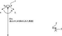
図1は、本実施の形態における無人飛行体と操縦器との位置関係を説明するための概略図であり、図2は、本実施の形態における操縦器の外観の一例を示す図である。 FIG. 1 is a schematic view for explaining the positional relationship between the unmanned aerial vehicle and the pilot in the present embodiment, and FIG. 2 is a diagram showing an example of the appearance of the pilot in the present embodiment.
図1は、無人飛行体1、操縦器2及び操縦者3の位置関係を示している。図1に示す無人飛行体1は、操縦器2を用いて操作され、操縦者3は、操縦器2を用いて無人飛行体1を遠隔操縦する。また、無人飛行体1の位置リセット動作前の無人飛行体1の前進方向は、矢印4の方向であり、無人飛行体1の位置リセット動作後の前進方向は、矢印5の方向であり、位置リセット動作後の方向5は、操縦器2の方向、すなわち操縦者3の方向を向いている。 FIG. 1 shows the positional relationship between the unmanned
ここで、図2に示すように、操縦器2は、アンテナ401、右スティック402、左スティック403、主電源スイッチ404、及び位置リセットスイッチ405を備える。 Here, as shown in FIG. 2, the
アンテナ401は、無人飛行体1との通信に用いる。右スティック402及び左スティック403は、操縦者3の入力を受け付ける。右スティック402及び左スティック403は、それぞれ、上下左右に可動である。主電源スイッチ404は、主電源をオン又はオフするためのスイッチである。位置リセットスイッチ405は、無人飛行体1の位置をリセットするためのスイッチである。 The
また、右スティック402及び左スティック403の十字状の矢印は、無人飛行体1の移動方向(例えば、前進方向、後退方向、右方向、及び左方向)と対応付けられている。例えば、上向き矢印が無人飛行体1の前進方向に対応付けられている場合、操縦者3が右スティック402又は左スティック403を上方向に傾けると、無人飛行体1は前進方向に移動する。 Further, the cross-shaped arrows of the
また、操縦者3が位置リセットスイッチ405を押下することにより、図1に示すように、無人飛行体1を、あらかじめ決められた高さ、例えば、地上高30mで停止させるホバリングを開始させるとともに、無人飛行体1の向き、具体的には、無人飛行体1の前進方向を操縦者3が位置する方向に向ける。実際には、無人飛行体1は、操縦者3の位置は把握できないため、無人飛行体1は、操縦器2の位置を操縦者3の位置であると仮定して、その位置に自機の前進方向を向けて、ホバリングする。このことにより、操縦者3は、操縦器2の右スティック402又は左スティック403を操作することにより、無人飛行体1に対して前進を指示することができるので、無人飛行体1が操縦者3に向かって戻ってくるように構成できる。 Further, when the operator 3 presses the position
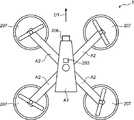
図3は、本実施の形態における無人飛行体及び操縦器を備えた飛行制御システムの構成の一例を示すブロック図であり、図4は、本実施の形態における無人飛行体の外観の一例を示す図である。 FIG. 3 is a block diagram showing an example of the configuration of a flight control system including an unmanned aerial vehicle and a pilot according to the present embodiment, and FIG. 4 shows an example of the appearance of the unmanned aerial vehicle according to the present embodiment. It is a figure.
図3に示すように、飛行制御システム200は、無人飛行体1と、操縦器2とを備え、無線通信を介して、相互に接続可能である。操縦器2は、第二位置取得部221、第二無線通信部222、制御部223、位置リセットスイッチ405、及び入力部225を備える。制御部223は、第二位置取得部221、第二無線通信部222、位置リセットスイッチ405、及び入力部225の制御を行う。 As shown in FIG. 3, the
第二位置取得部221は、操縦器2の位置を示す位置情報(例えば、経度及び緯度の情報)を取得する。第二位置取得部221は、例えば、GPSまたはGLONASSなどの位置情報システムを用いるセンサーである。第二無線通信部222は、無線通信を利用して、無人飛行体1と通信を行い、情報の送受信を行う。第二無線通信部222が使用する無線通信方式は、WiFiなどの無線LANでもよいし、ラジコンなどに用いられる2.4GHz帯の無線通信でもよいし、赤外線などの光学的な通信でもよい。 The second
入力部225は、図2に示す右スティック402及び左スティック403等から構成され、無人飛行体1に対する操縦者3の入力指示を受け付ける。位置リセットスイッチ405は、図2に例示したように、操縦器2の操作面の右側下部に装備されたスイッチであり、操縦者3は、無人飛行体1の制御が困難と判断した際に押すことができる。具体的には、操縦者3が位置リセットスイッチ405を押す(ONにする)ことにより、無人飛行体1は、位置リセット動作を開始する。 The
上記の操作により、位置リセットスイッチ405は、ONされたことを検知すると、制御部223に位置リセット指示を通知する。制御部223は、位置リセットスイッチ405が押されたときに、リセット指示を受け取り、第二無線通信部222を介して、位置リセット動作開始を指示する位置リセットコマンドと、第二位置取得部221が取得した操縦器2の位置情報とを無人飛行体1に送信する制御を実施する。 When the position
次に、図4を参照して、無人飛行体1は、本体A1と、4本の支持部A2と、無人飛行体1の推進力を発生させる4個の駆動部207と、撮影用のカメラ208とを備える。駆動部207は、本体A1から四方へ延在する支持部A2の先端に取り付けられる。本体A1の上側には、第一位置取得部203が取り付けられている。 Next, referring to FIG. 4, the unmanned
本体A1の内部には、図3に示す姿勢制御部201、姿勢決定部202、第一無線通信部204、プリセット高度記憶部205、及び制御部206が収納されている。本体A1の先端部には、カメラ208が取り付けられ、カメラ208は、前方又は前方下方の対象物を撮影する撮影部であり、撮影方向D1の対象物を撮影することができる。例えば、図4に示す無人飛行体1では、カメラ208の撮影方向D1が無人飛行体1の前進方向に設定されており、操縦者3が右スティック402又は左スティック403を上方向に傾けると、無人飛行体1は、撮影方向D1(無人飛行体1の前進方向)に移動する。 The
再び、図3を参照して、制御部206は、無人飛行体1の飛行を制御する。駆動部207は、プロペラと、プロペラを回転させるモータとからなる。制御部206は、駆動部207のプロペラの回転数を適宜制御することで、無人飛行体1の移動方向や飛行状態を制御する。なお、図4では、無人飛行体1は、4個の駆動部207を有しているが、これに限定されず、例えば、5個以上の駆動部を用いてもよい。 Again, with reference to FIG. 3, the
第一位置取得部203は、無人飛行体1に実装され、無人飛行体1の位置を示す位置情報(例えば、経度及び緯度の情報)を取得する機能を有する。第一位置取得部203は、例えば、GPSまたはGLONASSなどの位置情報システムを用いるセンサーである。 The first
第一無線通信部204は、無線通信を利用して操縦器2と通信を行い、情報の送受信を行う。第一無線通信部204は、操縦器2から操作指示を受信する。第一無線通信部204が使用する無線通信方式は、WiFiなどの無線LANでもよいし、ラジコンなどに用いられる2.4GHz帯の無線通信でもよいし、赤外線などの光学的な通信でもよい。 The first
本実施の形態において、第一無線通信部204及び第二無線通信部222は、無人飛行体を無線で制御するためのコマンドを、無人飛行体1と操縦器2の間で送受信する機能を有する。無線通信を利用して、位置リセットスイッチ405を押した場合に、位置リセット動作開始を指示する位置リセットコマンドを、操縦器2から無人飛行体1に送信する。また、無線通信を利用して、操縦器2の位置情報を無人飛行体1に送信することができる。 In the present embodiment, the first
プリセット高度記憶部205は、あらかじめ決められた位置リセット時の高度を記憶しておくメモリである。高度を表す情報は、海抜でもよいし、地上高でもよく、適切なホバリング時の高度を数値化して記憶できるものであればよい。本例では、地上高30mとした。 The preset
姿勢決定部202は、第一位置取得部203及び第二位置取得部221より入手される無人飛行体1及び操縦器2のそれぞれの位置情報を用いて、無人飛行体1の移動方向、例えば、前進方向を操縦器2に向けるために必要な回転角を求めるための機能を有する。姿勢決定部202は、操縦器2の位置及び無人飛行体1の位置に基づいて、無人飛行体1の移動方向、例えば、前進方向を、所定の方向、例えば、操縦器の位置する方向に向ける回転角θを決定する。 The
姿勢制御部201は、コンパスを備え、無人飛行体1の高度及び進行方向を制御するための機能を有し、操縦器2からの操作指示に基づいて無人飛行体1の飛行を制御する。また、姿勢制御部201は、プリセット高度記憶部205及び姿勢決定部202から、高さ方向の数値及び飛行体の向きを示すパラメータを入力され、姿勢決定部202が決定した回転角に基づいて無人飛行体1を制御する。 The
ここで、パラメータとして、極座標平面における角度θを用いる。姿勢制御部201は、入力したパラメータに従い、無人飛行体1の高度及び向き(姿勢)を制御する。例えば、姿勢制御部201は、パラメータとして通知された角度θに一致するように、無人飛行体1の向きを制御する。 Here, the angle θ in the polar coordinate plane is used as a parameter. The
なお、位置リセットスイッチ405は、単体のスイッチで構成されてもよいし、複数のスイッチの組み合わせでもよい。位置リセットスイッチ405は、他の用途のスイッチを所定のパターン、例えば、決められた回数だけON/OFFを繰り返す等のコンビネーションを用いて実現してもよい。さらに、位置リセットスイッチ405は、操縦器2の外側に物理的に装備したスイッチでなく、操縦器2にタッチパネルを設け、その画面上にボタンを表示し、操縦者3に操作させるように構成してもよい。 The position reset
(位置リセットのための飛行制御処理の詳細)
次に、本実施の形態の無人飛行体1の飛行制御方法の動作の詳細について、図5のフローチャートを用いながら説明する。(Details of flight control processing for position reset)
Next, the details of the operation of the flight control method of the unmanned
まず、操縦器2の位置リセットスイッチ405が操縦者3によって押されると(ステップS10がYes)、位置リセットスイッチ405は、制御部223に位置リセット指示を通知し、制御部223は、位置リセット指示を受け取り、位置リセット処理を開始する(ステップS11)。 First, when the position
次に、制御部223は、第二位置取得部221が取得した操縦器2の位置(例えば、経度及び緯度)を示す位置情報(X1,Y1)を受け取る(ステップS12)。 Next, the
次に、制御部223は、位置リセット動作開始を指示する位置リセットコマンドと、操縦器2の位置情報(X1,Y1)とを、第二無線通信部222を介して無人飛行体1に送信する(ステップS13)。なお、位置リセットコマンドにパラメータの一つとして位置情報を含んでもよい。また、位置リセットコマンドを送信した後に、別のコマンドとして位置情報を送信してもよい。 Next, the
一方、無人飛行体1の姿勢決定部202は、操縦器2がステップS13で送信した位置リセットコマンドを、第一無線通信部204を介して受信する(ステップS20がYes)。すなわち、姿勢決定部202は、位置リセットコマンドを受け取り、位置リセット動作を開始する。 On the other hand, the
次に、姿勢決定部202は、操縦器2が送信した位置情報(X1,Y1)を取得する(ステップS21)。 Next, the
次に、姿勢決定部202は、第一位置取得部203から無人飛行体1の位置(例えば、経度及び緯度)を示す位置情報(X2,Y2)を取得する(ステップS22)。 Next, the
次に、姿勢決定部202は、操縦器2の位置情報(X1,Y1)と無線飛行体1の位置情報(X2,Y2)とを用いて、無人飛行体1の向くべき方向を算出する(ステップS23)。ここでの無人飛行体1の向くべき方向とは、無人飛行体1の前進方向が操縦器2に向くことを意味する。具体的には、姿勢決定部202は、無人飛行体1の前進方向を操縦器2に向けるために必要な回転角を算出する。姿勢決定部202は、算出した回転角をパラメータとして姿勢制御部201に通知する。 Next, the
なお、無人飛行体1の向くべき方向(移動方向)は、無人飛行体1の前進方向が操縦器2の方向を向くだけではなく、他の向きであってもよい。すなわち、無人飛行体1の向くべき方向(移動方向)は、操縦器2の操作(例えば、右スティック402及び/又は左スティック403の操作)により、無人飛行体1がどの方向に移動するのかを操縦者が把握できる方向であれば、種々の方向を用いることができる。例えば、無人飛行体1の後退方向、無人飛行体1を上から見た場合の右方向又は左方向等の他の方向であってもよく、所定の方位(北方向、西方向、南方向、東方向等)であってもよい。 The direction (movement direction) that the unmanned
また、本実施の形態では、カメラ208の撮影方向D1を無人飛行体1の前進方向(移動方向)としたが、この例に特に限定されず、カメラ208の有無に拘らず、無人飛行体1の特定の方向(例えば、先細形状を有する本体A1の先端方向)を前進方向(移動方向)とする等の種々の変更が可能である。 Further, in the present embodiment, the shooting direction D1 of the
次に、姿勢制御部201は、姿勢決定部202から通知されたパラメータに従い、駆動部207へ無人飛行体1の姿勢を変更する制御を行う(ステップS24)。具体的には、無人飛行体1は、パラメータとして通知された回転角に従い回転することで、自身の向きを変更する。この結果、無人飛行体1は、前進方向を操縦者3の方向に向けホバリングすることができる。 Next, the
上記のように、姿勢決定部202は、操縦器2の位置、すなわち、ほぼ操縦者3の位置と推定可能な座標(X1,Y1)と、無人飛行体1の位置を示す座標(X2,Y2)とを取得する。姿勢決定部202は、取得した2つの座標(X1,Y1)と(X2,Y2)を用いて、下記のように計算を実施する。 As described above, the
これらの関係を図6に示す。 These relationships are shown in FIG.
まず、2つの経度及び緯度の情報を直交座標とみて、無人飛行体1の自位置を原点とした極座標へと変換を行う。これにより、無人飛行体1が、操縦器2が位置する方向に向くための回転角θを得る。 First, the information of the two longitudes and latitudes is regarded as Cartesian coordinates, and the unmanned
すなわち、X=X1−X2、Y=Y1−Y2とすると、tanθ=X/Yの関係が成り立つ。したがって、これを解いて、θ=arctan(X/Y)により、必要な回転角θを得ることができる。ここで、arctanは、アークタンジェントを求める関数である。 That is, if X = X1-X2 and Y = Y1-Y2, the relationship of tan θ = X / Y is established. Therefore, by solving this, the required rotation angle θ can be obtained by θ = arctan (X / Y). Here, arctan is a function for obtaining an arc tangent.
姿勢決定部202は、計算により求めた回転角θを、姿勢制御部201に通知する。無人飛行体1は、通知された回転角θに基づき必要な回転をして、結果として前進方向を操縦者3の方向に向けホバリングすることができる。なお、回転角の決定方法は、上記の例に特に限定されず、経度及び緯度以外の他の位置情報等を用いて計算してもよく、種々の変更が可能である。 The
また、プリセット高度記憶部205が、あらかじめ設定された位置リセットのためのプリセット高度を記憶している場合に、姿勢制御部201は、姿勢決定部202から回転角θと共に、プリセット高度記憶部205から高度をパラメータとして受け取り、無人飛行体1の高度についても制御を実施する。 Further, when the preset
以上述べてきたように、操縦者3が手元にある操縦器2の位置リセットスイッチ405をONにすることにより、無人飛行体1が無制御状態となった場合でも、無人飛行体1は、決められた高度で、かつ、自機の前進方向を操縦器2の位置、すなわち操縦者3の位置に向けて静止(ホバリング)させることができる。つまり、操縦者3は、目視が困難な遠隔地を飛行中の無人飛行体1であっても、容易に無人飛行体1の姿勢(向き)を判断でき、容易に制御状態に回復することが可能となる。 As described above, the unmanned
このことから、操縦者3は、無人飛行体1に対し前進指示を送ることだけで、操縦者3の手元に無人飛行体1を戻すように制御することが可能となり、操縦の回復が容易に行え、機材の回収にも極めて有用である。 From this, the pilot 3 can control to return the unmanned
上記のように、本実施の形態にかかる無人飛行体1の飛行制御方法によれば、操縦者が無人飛行体を見失しなったときや、無人飛行体の制御を失ったような場合に、一旦無人飛行体1をホバリングさせ、さらに無人飛行体1の向きを自分の方向に向けることにより、無人飛行体1の操縦を回復することが容易になる。 As described above, according to the flight control method of the unmanned
これにより、無人飛行体1の墜落やフライアウェイ(無制御状態)になる可能性を低減することができる。 This makes it possible to reduce the possibility that the unmanned
本開示に係る無人飛行体の飛行制御方法は、位置リセットスイッチを用い、位置リセットスイッチが押されると、無人飛行体の向きを操縦器の位置に向けてホバリングする機能を有し、操縦者により遠隔制御される無人飛行体において有用である。 The flight control method for an unmanned aerial vehicle according to the present disclosure uses a position reset switch and has a function of hovering the direction of the unmanned aerial vehicle toward the position of the controller when the position reset switch is pressed. It is useful in remotely controlled unmanned aerial vehicles.
1 無人飛行体
2 操縦器
201 姿勢制御部
202 姿勢決定部
203 第一位置取得部
204 第一無線通信部
205 プリセット高度記憶部
206 制御部
207 駆動部
221 第二位置取得部
222 第二無線通信部
223 制御部
225 入力部
401 アンテナ
402 右スティック
403 左スティック
404 主電源スイッチ
405 位置リセットスイッチ1
Claims (6)
Translated fromJapanese前記操縦器から操作指示を受信する無線通信部と、
前記無人飛行体の位置を取得する位置取得部と、
前記無人飛行体の移動方向を決定する姿勢決定部と、
前記操作指示に基づいて前記無人飛行体の飛行を制御する制御部と、を備え、
前記無線通信部は、前記操縦器から前記操縦器の位置を受信し、
前記姿勢決定部は、前記操縦器の位置及び前記無人飛行体の位置に基づいて、前記無人飛行体の移動方向を前記操縦器の位置する方向に決定し、
前記制御部は、決定された前記移動方向に基づいて前記無人飛行体を制御する、
無人飛行体。An unmanned aerial vehicle operated using a pilot
A wireless communication unit that receives operation instructions from the controller,
A position acquisition unit that acquires the position of the unmanned aerial vehicle, and
The attitude determination unit that determinesthe movement direction of the unmanned aerial vehicle, and
A control unit that controls the flight of the unmanned aerial vehicle based on the operation instruction is provided.
The wireless communication unit receives the position of the steering unit oral before Symbol steering unit,
The attitude determining unit determines the moving direction of the unmanned aerial vehicle in the direction inwhich the pilot is located, based on the position of the pilot and the position of the unmanned aerial vehicle.
The control unit controls the unmanned aerial vehicle based onthe determinedmovement direction .
Unmanned aerial vehicle.
請求項1に記載の無人飛行体。The attitude determining unit determines a rotation angle that directs the forward direction of the unmanned aerial vehicle towardthe position of the controller based on the position of the controller and the position of the unmanned aerial vehicle.
The unmanned aerial vehicle according to claim 1.
請求項2に記載の無人飛行体。The posture determining unit sets the rotation angle to θ, the position of the controller to (X1, Y1), the position of the unmanned vehicle to (X2, Y2), and X = X1-X2, Y = Y1-. When Y2 is set, θ = arctan (X / Y) is used to determine the rotation angle θ.
The unmanned aerial vehicle accordingto claim2 .
前記制御部は、前記リセットコマンドが受信されると、前記操縦器の位置及び前記無人飛行体の位置に基づいて、前記無人飛行体の移動方向を前記操縦器の位置する方向に決定する When the reset command is received, the control unit determines the moving direction of the unmanned aerial vehicle in the direction in which the pilot is located, based on the position of the pilot and the position of the unmanned aerial vehicle.
請求項1〜3のいずれか1項に記載の無人飛行体。 The unmanned aerial vehicle according to any one of claims 1 to 3.
請求項1〜4のいずれかに記載の無人飛行体。Wherein the controlunit, the movement directionbefore Symbol unmanned air vehiclesin that the directionof the position of the steering unit, for controlling the unmanned air vehicle so as to further hovering a predetermined altitude,
The unmanned aerial vehicle according to any one of claims 1 to 4.
前記操縦器から操作指示を受信する無線通信ステップと、
前記無人飛行体の位置を取得する位置取得ステップと、
前記無人飛行体の移動方向を決定する姿勢決定ステップと、
前記操作指示に基づいて前記無人飛行体の飛行を制御する制御ステップと、を含み、
前記無線通信ステップにおいて、前記操縦器から前記操縦器の位置を受信し、
前記姿勢決定ステップにおいて、前記操縦器の位置及び前記無人飛行体の位置に基づいて、前記無人飛行体の移動方向を前記操縦器の位置する方向に決定し、
前記制御ステップにおいて、決定された前記移動方向に基づいて前記無人飛行体を制御する、
無人飛行体の飛行制御方法。It is a flight control method for unmanned aerial vehicles operated using a pilot.
A wireless communication step that receives an operation instruction from the controller, and
The position acquisition step for acquiring the position of the unmanned aerial vehicle and
The attitude determination step that determinesthe movement direction of the unmanned aerial vehicle and
Includes a control step that controls the flight of the unmanned aerial vehicle based on the operational instructions.
In the wireless communication step to receive the position of the steering unit oral before Symbol steering unit,
In the attitude determination step, the moving direction of the unmanned aerial vehicleis determined inthe direction in which the pilot is located, based on the position of the pilot and the position of the unmanned aerial vehicle.
In the control step, the unmanned aerial vehicle is controlled based onthe determinedmovement direction .
Flight control method for unmanned aerial vehicles.
Priority Applications (2)
| Application Number | Priority Date | Filing Date | Title |
|---|---|---|---|
| CN201610812735.3ACN106809386B (en) | 2015-11-30 | 2016-09-09 | Unmanned aerial vehicle and its flight control method |
| US15/352,000US10023310B2 (en) | 2015-11-30 | 2016-11-15 | Unmanned flying object and flight control method thereof |
Applications Claiming Priority (2)
| Application Number | Priority Date | Filing Date | Title |
|---|---|---|---|
| JP2015232676 | 2015-11-30 | ||
| JP2015232676 | 2015-11-30 |
Publications (2)
| Publication Number | Publication Date |
|---|---|
| JP2017105429A JP2017105429A (en) | 2017-06-15 |
| JP6767802B2true JP6767802B2 (en) | 2020-10-14 |
Family
ID=59059043
Family Applications (1)
| Application Number | Title | Priority Date | Filing Date |
|---|---|---|---|
| JP2016139983AActiveJP6767802B2 (en) | 2015-11-30 | 2016-07-15 | Unmanned aerial vehicle and its flight control method |
Country Status (2)
| Country | Link |
|---|---|
| JP (1) | JP6767802B2 (en) |
| CN (1) | CN106809386B (en) |
Families Citing this family (9)
| Publication number | Priority date | Publication date | Assignee | Title |
|---|---|---|---|---|
| JP2019085104A (en)* | 2017-11-06 | 2019-06-06 | 株式会社エアロネクスト | Flying body and method of controlling flying body |
| WO2019138466A1 (en)* | 2018-01-10 | 2019-07-18 | 楽天株式会社 | Unmanned aircraft control system, unmanned aircraft control method, and program |
| WO2019159232A1 (en)* | 2018-02-13 | 2019-08-22 | 楽天株式会社 | Unmanned air vehicle control system, unmanned air vehicle control method, and program |
| CN111566010B (en)* | 2018-02-28 | 2024-06-07 | 株式会社尼罗沃克 | Unmanned aerial vehicle, unmanned aerial vehicle control method, and computer-readable recording medium |
| JP6921026B2 (en)* | 2018-03-30 | 2021-08-18 | エスゼット ディージェイアイ テクノロジー カンパニー リミテッドSz Dji Technology Co.,Ltd | Transmitters, flying objects, flight control instruction methods, flight control methods, programs, and storage media |
| WO2020024185A1 (en)* | 2018-08-01 | 2020-02-06 | SZ DJI Technology Co., Ltd. | Techniques for motion-based automatic image capture |
| WO2021005809A1 (en)* | 2019-07-08 | 2021-01-14 | パナソニックIpマネジメント株式会社 | Information processing device, information processing method, and unmanned aerial vehicle |
| CN116261699A (en)* | 2020-12-29 | 2023-06-13 | 深圳市大疆创新科技有限公司 | Unmanned aerial vehicle and its control method, device, control terminal and storage medium |
| CN118294192B (en)* | 2024-04-07 | 2024-12-13 | 绍兴文理学院 | Unmanned aerial vehicle device for drilling tree cores and application method |
Family Cites Families (25)
| Publication number | Priority date | Publication date | Assignee | Title |
|---|---|---|---|---|
| FR2565372B1 (en)* | 1984-05-29 | 1987-09-18 | Trt Telecom Radio Electr | DISTANCE MEASUREMENT TERMINAL GUIDANCE OR LOCALIZATION SYSTEM FOR AIRCRAFT |
| JP3297830B2 (en)* | 1994-06-29 | 2002-07-02 | ヤンマー農機株式会社 | Helicopter remote control |
| JP2001209427A (en)* | 2000-01-28 | 2001-08-03 | Fuji Heavy Ind Ltd | Unmanned airplane remote control |
| JP4304009B2 (en)* | 2003-06-04 | 2009-07-29 | 富士重工業株式会社 | Unmanned aircraft control system |
| US8005563B2 (en)* | 2007-10-26 | 2011-08-23 | The Boeing Company | System for assembling aircraft |
| FR2958418B1 (en)* | 2010-04-06 | 2012-12-28 | Thales Sa | AIRCRAFT FLIGHT MANAGEMENT SYSTEM WITHOUT PILOT ON AIRCRAFT |
| KR101157484B1 (en)* | 2010-12-14 | 2012-06-20 | 주식회사 대한항공 | Uav automatic recovering method |
| EP2511781A1 (en)* | 2011-04-14 | 2012-10-17 | Hexagon Technology Center GmbH | Method and system for controlling an unmanned aircraft |
| KR20130081260A (en)* | 2012-01-06 | 2013-07-16 | 엘아이지넥스원 주식회사 | Apparatus for controlling unmanned vehicle and unmanned vehicle having the said apparatus |
| CN103576690B (en)* | 2012-07-25 | 2016-12-21 | 深圳市大疆创新科技有限公司 | A kind of no-manned machine distant control method and apparatus, unmanned plane |
| CN102945046A (en)* | 2012-11-15 | 2013-02-27 | 中国兵器工业计算机应用技术研究所 | Control method of unmanned aircraft |
| US9102406B2 (en)* | 2013-02-15 | 2015-08-11 | Disney Enterprises, Inc. | Controlling unmanned aerial vehicles as a flock to synchronize flight in aerial displays |
| CA2841685C (en)* | 2013-03-15 | 2021-05-18 | Panasonic Avionics Corporation | System and method for providing multi-mode wireless data distribution |
| CN103365298B (en)* | 2013-07-05 | 2017-06-20 | 深圳市大疆创新科技有限公司 | Flight assistance system and method for unmanned aerial vehicles |
| CN107065914B (en)* | 2013-07-05 | 2020-04-28 | 深圳市大疆创新科技有限公司 | Flight assistance method and device for unmanned aerial vehicle |
| JP6469962B2 (en)* | 2014-04-21 | 2019-02-13 | 薫 渡部 | Monitoring system and monitoring method |
| US9457901B2 (en)* | 2014-04-22 | 2016-10-04 | Fatdoor, Inc. | Quadcopter with a printable payload extension system and method |
| WO2016101227A1 (en)* | 2014-12-25 | 2016-06-30 | 深圳市大疆创新科技有限公司 | Flight auxiliary method and system of unmanned aerial vehicle, unmanned aerial vehicle, and mobile terminal |
| CN104820428B (en)* | 2015-04-20 | 2017-11-07 | 余江 | The memory-type flight path reproducting method and its device of a kind of unmanned plane |
| CN104881039A (en)* | 2015-05-12 | 2015-09-02 | 零度智控(北京)智能科技有限公司 | Method and system for returning of unmanned plane |
| CN204719540U (en)* | 2015-05-28 | 2015-10-21 | 余江 | Multi-rotor aerocraft |
| CN104898699B (en)* | 2015-05-28 | 2020-03-17 | 小米科技有限责任公司 | Flight control method and device and electronic equipment |
| CN104932526B (en)* | 2015-05-29 | 2020-08-28 | 深圳市大疆创新科技有限公司 | Control method of flight equipment and flight equipment |
| JP2017007603A (en)* | 2015-06-25 | 2017-01-12 | 三菱自動車工業株式会社 | Driving support control device |
| CN105045281A (en)* | 2015-08-13 | 2015-11-11 | 深圳一电科技有限公司 | Unmanned aerial vehicle flight control method and device |
- 2016
- 2016-07-15JPJP2016139983Apatent/JP6767802B2/enactiveActive
- 2016-09-09CNCN201610812735.3Apatent/CN106809386B/enactiveActive
Also Published As
| Publication number | Publication date |
|---|---|
| JP2017105429A (en) | 2017-06-15 |
| CN106809386B (en) | 2021-07-27 |
| CN106809386A (en) | 2017-06-09 |
Similar Documents
| Publication | Publication Date | Title |
|---|---|---|
| JP6767802B2 (en) | Unmanned aerial vehicle and its flight control method | |
| CN105469579B (en) | Somatosensory remote controller, somatosensory remote control flight system and somatosensory remote control flight method | |
| JP6671375B2 (en) | How to fly a drone | |
| US20200019189A1 (en) | Systems and methods for operating unmanned aerial vehicle | |
| US10222792B2 (en) | Drone piloting device adapted to hold piloting commands and associated control method | |
| KR101117207B1 (en) | Auto and manual control system for unmanned aerial vehicle via smart phone | |
| KR20190076982A (en) | Safety system for unmanned aircraft operation | |
| JP4012749B2 (en) | Remote control system | |
| EP3274779B1 (en) | Path-based flight maneuvering system | |
| US20140008496A1 (en) | Using handheld device to control flying object | |
| US11383834B2 (en) | Unmanned flying object and method of controlling unmanned flying object | |
| JP2011189929A (en) | Method and equipment for remote control of unmanned aircraft, particularly, rotary-wing unmanned aircraft | |
| JP2017065467A (en) | Drone and its control method | |
| WO2018232616A1 (en) | Methods and apparatuses related to transformable remote controllers | |
| WO2017222542A1 (en) | Unmanned aerial vehicle avoiding obstacles | |
| JP2001209427A (en) | Unmanned airplane remote control | |
| CN113614670A (en) | Method and equipment for controlling return flight of unmanned aerial vehicle | |
| KR20180025416A (en) | Drone flying control system and method using motion recognition and virtual reality | |
| JP6560479B1 (en) | Unmanned aircraft control system, unmanned aircraft control method, and program | |
| JP2020196355A (en) | Pilotless aircraft and pilotless aerial system | |
| KR20200002166A (en) | Drone manipulation method and device using wrist inclination | |
| JP2019051755A (en) | Maneuvering system of flight device | |
| US10023310B2 (en) | Unmanned flying object and flight control method thereof | |
| JP7289152B2 (en) | flight control system | |
| KR20190009504A (en) | One-hand remote control device for controlling drone |
Legal Events
| Date | Code | Title | Description |
|---|---|---|---|
| A621 | Written request for application examination | Free format text:JAPANESE INTERMEDIATE CODE: A621 Effective date:20190131 | |
| A977 | Report on retrieval | Free format text:JAPANESE INTERMEDIATE CODE: A971007 Effective date:20200123 | |
| A131 | Notification of reasons for refusal | Free format text:JAPANESE INTERMEDIATE CODE: A131 Effective date:20200204 | |
| A521 | Request for written amendment filed | Free format text:JAPANESE INTERMEDIATE CODE: A523 Effective date:20200427 | |
| TRDD | Decision of grant or rejection written | ||
| A01 | Written decision to grant a patent or to grant a registration (utility model) | Free format text:JAPANESE INTERMEDIATE CODE: A01 Effective date:20200901 | |
| A61 | First payment of annual fees (during grant procedure) | Free format text:JAPANESE INTERMEDIATE CODE: A61 Effective date:20200918 | |
| R150 | Certificate of patent or registration of utility model | Ref document number:6767802 Country of ref document:JP Free format text:JAPANESE INTERMEDIATE CODE: R150 |