JP6766574B2 - Rotating electric machine - Google Patents
Rotating electric machineDownload PDFInfo
- Publication number
- JP6766574B2 JP6766574B2JP2016198335AJP2016198335AJP6766574B2JP 6766574 B2JP6766574 B2JP 6766574B2JP 2016198335 AJP2016198335 AJP 2016198335AJP 2016198335 AJP2016198335 AJP 2016198335AJP 6766574 B2JP6766574 B2JP 6766574B2
- Authority
- JP
- Japan
- Prior art keywords
- stator
- gap rotor
- radial gap
- rotor
- teeth
- Prior art date
- Legal status (The legal status is an assumption and is not a legal conclusion. Google has not performed a legal analysis and makes no representation as to the accuracy of the status listed.)
- Active
Links
Images


Landscapes
- Iron Core Of Rotating Electric Machines (AREA)
- Synchronous Machinery (AREA)
- Permanent Magnet Type Synchronous Machine (AREA)
Description
Translated fromJapanese本発明に係る実施形態は回転電機に関する。 The embodiment according to the present invention relates to a rotary electric machine.
電機子コイルで発生する空間高調波成分を利用して外部からの電力供給なくマグネットトルクを得る回転電機が知られている。 A rotary electric machine that obtains magnet torque without supplying electric power from the outside by using a spatial harmonic component generated by an armature coil is known.
従来の回転電機は、いわゆるアキシャルギャップ型であって、モータシャフトを中心にして回転駆動する2つのロータと、シャフトの軸方向において2つのロータに挟まれるステータと、備えている。ステータは、シャフト周りに配置される複数の電機子コイルを備え、ロータのそれぞれは、シャフト周りに配置される複数の誘導コイルおよび複数の界磁コイルと、誘導コイルで発生する誘導電流を整流して界磁コイルに供給するダイオードと、を備えている。 A conventional rotary electric machine is a so-called axial gap type, and includes two rotors that are rotationally driven around a motor shaft and a stator that is sandwiched between the two rotors in the axial direction of the shaft. The stator comprises a plurality of armature coils arranged around the shaft, and each of the rotors rectifies a plurality of induction coils and a plurality of field coils arranged around the shaft and an induction current generated by the induction coils. It is equipped with a diode that supplies the field coil.
従来の回転電機は、ステータコアからロータコアに鎖交させる磁束に空間高調波成分が重畳している。このため、2つのロータは、ステータから鎖交される磁束の空間高調波成分の磁束密度の変化を利用して誘導コイルに誘導電流を発生させ、この電流を界磁コイルに供給して起磁力を得ている。 In the conventional rotary electric machine, the space harmonic component is superimposed on the magnetic flux interlinking from the stator core to the rotor core. Therefore, the two rotors generate an induced current in the induction coil by utilizing the change in the magnetic flux density of the space harmonic component of the magnetic flux interlinking from the stator, and supply this current to the field coil to generate the magnetomotive force. Is getting.
そして、従来の回転電機は、界磁コイルが発生させた磁束をロータコアの端面からステータコアの端面に鎖交させ、主回転力を発生する電機子コイルの磁束とは別にマグネットトルクを得て、2つのロータの回転駆動を補助する。 Then, in the conventional rotary electric machine, the magnetic flux generated by the field coil is interlinked from the end face of the rotor core to the end face of the stator core, and a magnet torque is obtained separately from the magnetic flux of the armature coil that generates the main rotational force. Assists in the rotational drive of one rotor.
従来の回転電機は、誘導コイルと界磁コイルとを別個に設けることで、両コイルを1つのコイルで兼用する場合に生じる磁気的な干渉を低減させている。 In the conventional rotary electric machine, the induction coil and the field coil are provided separately to reduce the magnetic interference that occurs when both coils are used in combination with one coil.
しかし、従来の回転電機は、誘導コイルと界磁コイルとを同一のロータティースに巻いているため、コイルの巻き数に制約を受けてしまう。 However, in the conventional rotary electric machine, since the induction coil and the field coil are wound on the same rotor, the number of coil turns is restricted.
誘導電流も起磁力もコイルの巻き数に比例するため、コイルの巻き数の制約が制約されることは、空間高調波成分の利用を制限してしまう。 Since both the induced current and the magnetomotive force are proportional to the number of turns of the coil, the restriction on the number of turns of the coil limits the use of the spatial harmonic component.
そこで、本発明は、誘導コイルおよび界磁コイルの巻き数を確保し易く、ひいては空間高調波成分をより効率的に利用可能な回転電機を提供することを目的とする。 Therefore, an object of the present invention is to provide a rotary electric machine that can easily secure the number of turns of the induction coil and the field coil, and can more efficiently use the space harmonic component.
前記の課題を解決するため本発明の実施形態に係る回転電機は、筒状のステータと、前記ステータの軸方向の少なくともいずれか一方に配置され隙間を隔てて前記ステータに対面するアキシャルギャップロータと、前記ステータの径方向内側または外側に配置され隙間を隔てて前記ステータに対面するラジアルギャップロータと、を備え、前記ステータは、ステータコアと、前記ステータコアに設けられ前記ステータコアの周方向に等間隔で並ぶ複数のステータティースと、前記ステータコアまたは前記ステータティースに巻かれる電機子コイルと、を有し、前記アキシャルギャップロータは、前記ステータコアに対面し前記アキシャルギャップロータコアの周方向に等間隔で並ぶ複数のアキシャルギャップロータティースと、前記アキシャルギャップロータティースに巻かれ前記ステータで発生する磁束に基づいて誘導電流を誘起させる誘導コイルと、を有し、前記ラジアルギャップロータは、前記ステータコアに対面するラジアルギャップロータコアと、前記ラジアルギャップロータコアに設けられ前記ラジアルギャップロータコアの周方向に等間隔で並ぶ複数のラジアルギャップロータティースと、前記ラジアルギャップロータティースのそれぞれに設けられる永久磁石と、隣り合う前記ラジアルギャップロータティースの間に配置される磁路部材と、前記磁路部材に巻かれ前記誘導電流が流れると磁界を発生させる界磁コイルと、を有し、前記ラジアルギャップロータティースは、前記永久磁石よりも前記ステータ側に配置され前記永久磁石と前記磁路部材との間、および前記永久磁石と前記ステータティースとの間に磁束を通す磁路としての先端部を有している。In order to solve the above problems, the rotary electric machine according to the embodiment of the present invention includes a tubular stator and an axial gap rotor which is arranged in at least one of the axial directions of the stator and faces the stator with a gap. , A radial gap rotor arranged on the inside or outside of the stator in the radial direction and facing the stator with a gap, the stator is provided on the stator core and at equal intervals in the circumferential direction of the stator core. A plurality of stator teeth arranged side by side and an armature coil wound around the stator core or the stator teeth are provided, and the axial gap rotor faces the stator core and is arranged at equal intervals in the circumferential direction of the axial gap rotor core. The radial gap rotor has an axial gap rotor and an induction coil that is wound around the axial gap rotor and induces an induced current based on a magnetic flux generated in the stator, and the radial gap rotor faces the stator core. A plurality of radial gap rotor teeth provided in the radial gap rotor core and arranged at equal intervals in the circumferential direction of the radial gap rotor core, permanent magnets provided in each of the radial gap rotor teeth, and adjacent radial gap rotor teeth. a magnetic path member disposed between said wound magnetic path memberhave a, a field coil for generating a magnetic field when the induced currentflows, the radial gap rotor teeth, said than said permanent magnet andhave a tip portion of a magnetic path passing the magnetic flux between the between being placed on the stator side and the permanent magnet and the magnetic path member, and said permanent magnet and the stator teeth.
また、本発明の実施形態に係る回転電機は、筒状のステータと、前記ステータの軸方向の少なくともいずれか一方に配置され隙間を隔てて前記ステータに対面するアキシャルギャップロータと、前記ステータの径方向内側または外側に配置され隙間を隔てて前記ステータに対面するラジアルギャップロータと、を備え、前記ステータは、ステータコアと、前記ステータコアに設けられ前記ステータコアの周方向に等間隔で並ぶ複数のステータティースと、前記ステータコアまたは前記ステータティースに巻かれる電機子コイルと、を有し、前記ラジアルギャップロータは、前記ステータコアに対面すし周方向に等間隔で並ぶ複数のラジアルギャップロータティースと、前記ラジアルギャップロータティースに巻かれ前記ステータで発生する磁束に基づいて誘導電流を誘起させる誘導コイルと、を有し、前記アキシャルギャップロータは、前記ステータコアに対面するアキシャルギャップロータコアと、前記アキシャルギャップロータコアに設けられ前記アキシャルギャップロータコアの周方向に等間隔で並ぶ複数のアキシャルギャップロータティースと、前記アキシャルギャップロータティースのそれぞれに設けられる永久磁石と、隣り合う前記アキシャルギャップロータティースの間に配置される磁路部材と、前記磁路部材に巻かれ前記誘導電流が流れると磁界を発生させる界磁コイルと、を有している。 Further, the rotary electric machine according to the embodiment of the present invention includes a tubular stator, an axial gap rotor arranged in at least one of the axial directions of the stator and facing the stator with a gap, and a diameter of the stator. A plurality of stator teeth provided on the inner or outer side of the direction and facing the stator with a gap thereof are provided, and the stator is provided on the stator core and arranged at equal intervals in the circumferential direction of the stator core. The radial gap rotor has a plurality of radial gap rotor teeth that are arranged at equal intervals in the circumferential direction facing the stator core, and the radial gap rotor, and the armature coil wound around the stator core or the stator teeth. It has an induction coil wound around a tooth and inducing an induced current based on a magnetic field generated by the stator, and the axial gap rotor is provided on the axial gap rotor core facing the stator core and the axial gap rotor core. A plurality of axial gap rotors arranged at equal intervals in the circumferential direction of the axial gap rotor core, permanent magnets provided in each of the axial gap rotor teeth, and a magnetic path member arranged between the adjacent axial gap rotor teeth. It has a field coil that is wound around the magnetic path member and generates a magnetic field when the induced current flows.
本発明によれば、誘導コイルおよび界磁コイルの巻き数を確保し易く、ひいては空間高調波成分をより効率的に利用可能な回転電機を提供できる。 According to the present invention, it is possible to easily secure the number of turns of the induction coil and the field coil, and it is possible to provide a rotary electric machine capable of more efficiently utilizing the space harmonic component.
以下、本発明に係る回転電機の実施形態について図1から図15を参照して説明する。 Hereinafter, embodiments of the rotary electric machine according to the present invention will be described with reference to FIGS. 1 to 15.
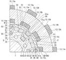
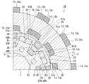
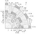
図1は、本発明の実施形態に係る回転電機を回転軸に沿う方向から見た図である。 FIG. 1 is a view of a rotary electric machine according to an embodiment of the present invention as viewed from a direction along a rotation axis.
図2は、本発明の実施形態に係る回転電機を回転軸に直交する方向から見た図である。 FIG. 2 is a view of the rotary electric machine according to the embodiment of the present invention as viewed from a direction orthogonal to the rotation axis.
図1および図2に示すように、本実施形態に係る回転電機1は、概略円柱形状の外観を有する。回転電機1は、筒状のステータ2と、ステータ2の軸方向の少なくともいずれか一方に配置され、隙間G1を隔ててステータ2に対面するアキシャルギャップロータ3と、ステータ2の径方向内側または外側に配置され、隙間G2を隔ててステータ2に対面するラジアルギャップロータ5と、を備えている。つまり、回転電機1は、いわゆるアキシャルギャップ型およびラジアルギャップ型の両方の構造を兼ね備えている。 As shown in FIGS. 1 and 2, the rotary
なお、図1は、ステータ2の径方向内側に配置されるラジアルギャップロータ5を備える、いわゆるインナーロータ型の回転電機1の図である。また、図2は、ステータ2の軸方向の両方からステータ2を挟む一対のアキシャルギャップロータ3を備える回転電機1の図である。 Note that FIG. 1 is a diagram of a so-called inner rotor type rotary
また、回転電機1は、ステータ2の中心線に沿って配置される回転軸6を備えている。回転軸6は、ステータ2を挟む一対のアキシャルギャップロータ3を回転一体に支持している。また、回転軸6は、ステータ2の内部にラジアルギャップロータ5を回転一体に支持している。つまり、回転軸6は、アキシャルギャップロータ3およびラジアルギャップロータ5を回転一体に支持している。アキシャルギャップロータ3、ラジアルギャップロータ5、よび回転軸6は、ステータ2の中心線を中心に回転する。回転軸6は、ステータ2、またはステータ2、ラジアルギャップロータ5、およびアキシャルギャップロータ3を収容するケーシング7に軸受(図示省略)を介して回転可能に支持されている。 Further, the rotary
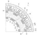
図3は、本発明の実施形態に係る回転電機のステータの斜視図である。 FIG. 3 is a perspective view of a stator of a rotary electric machine according to an embodiment of the present invention.
図4は、本発明の実施形態に係る回転電機のステータコアの斜視図である。 FIG. 4 is a perspective view of a stator core of a rotary electric machine according to an embodiment of the present invention.
図1および図2に加えて図3および図4に示すように、本実施形態に係る回転電機1のステータ2は、円筒形状のステータコア11と、ステータコア11に設けられ、ステータコア11の周方向に等間隔で並ぶ複数のステータティース12と、ステータコア11またはステータティース12に巻かれる電機子コイル13と、を備えている。 As shown in FIGS. 3 and 4 in addition to FIGS. 1 and 2, the
ステータコア11は、高透磁率の磁性材料で製作されている。ステータコア11の中心線方向を臨む面、つまり天面および底面をアキシャル面と呼び、ステータコア11の径方向を臨む面、つまり内周面および外周面をラジアル面と呼ぶ。 The
複数、例えば12のステータティース12は、放射状に配置されている。ステータティース12は、ステータコア11と同じ材料で一体成型されている。隣り合う一対のステータティース12は、ステータスロットを画定している。換言すると、ステータスロットは、隣り合うステータティース12の側面に挟まれる空間である。 A plurality of, for example, 12
それぞれのステータティース12は、ステータコア11の2つのアキシャル面から突出する第一ティース部15と、ステータコア11のラジアル面から突出する第二ティース部16と、を備えている。第一ティース部15は、ステータコア11の厚みの中央部から外側および内側へ向かって狭まる略六角柱状の外観を有している。第二ティース部16は、第一ティース部15の内側の形状に整合してステータコア11の中心線に向かって狭まる台形状を有している。第二ティース部16は、ステータコア11の内周面を長手方向、つまりステータコア11の中心線に平行な方向へ延びている。 Each
電機子コイル13は、三相交流電源(図示省略)に接続される。電機子コイル13は、ステータスロットに配置され、ステータコア11に巻かれている。U相、V相、およびW相のそれぞれに接続される電機子コイル13a、13b、13cが、例えば4極ずつ並列にトロイダル集中巻きされている。各相の電機子コイル13は、ステータティース12を両脇から挟んでいる。なお、電機子コイル13は、ステータティース12に巻かれていても良い。 The
ステータ2は、電機子コイル13に交流電力が通電することによって磁束を発生させ、その磁束をステータコア11のアキシャル面からアキシャルギャップロータ3に鎖交させ、ステータコア11のラジアル面からラジアルギャップロータ5に鎖交させる。ステータティース12は、電機子コイル13に交流電力が通電することによってラジアルギャップロータ5を回転させる磁束を発生する電磁石として機能する。 The
図5は、本発明の実施形態に係る回転電機のアキシャルギャップロータを回転軸に沿う方向から見た図である。 FIG. 5 is a view of the axial gap rotor of the rotary electric machine according to the embodiment of the present invention as viewed from the direction along the rotation axis.
図6は、本発明の実施形態に係る回転電機のアキシャルギャップロータを回転軸に直交する方向から見た図である。 FIG. 6 is a view of the axial gap rotor of the rotary electric machine according to the embodiment of the present invention as viewed from a direction orthogonal to the rotation axis.
図1および図2に加えて図5および図6に示すように、本実施形態に係る回転電機1のアキシャルギャップロータ3は、非磁性部材21と、ステータコア11に対面し周方向に等間隔で並ぶ複数のアキシャルギャップロータティース22と、アキシャルギャップロータティース22に巻かれステータ2で発生する磁束に基づいて誘導電流を誘起させる誘導コイル23と、を備えている。 As shown in FIGS. 5 and 6 in addition to FIGS. 1 and 2, the axial gap rotor 3 of the rotary
アキシャルギャップロータ3は、非磁性部材21、複数のアキシャルギャップロータティース22、および誘導コイル23を、例えば樹脂を硬化させて一体化したものである。 The axial gap rotor 3 is formed by integrating a
非磁性部材21は、非磁性金属(例えばアルミニウム)や樹脂のような非磁性材料で製作されている。非磁性部材21には、アキシャルギャップロータティース22が取り付けられ、複数のアキシャルギャップロータティース22の相対的な位置が定められている。非磁性部材21(および樹脂)によって、アキシャルギャップロータ3とラジアルギャップロータとの間、および、複数のアキシャルギャップロータティースの間の磁気抵抗が高められている。 The
複数、例えば8つのアキシャルギャップロータティース22は、第二次高調波成分を導くため放射状に配置されたセグメント構造を有している。アキシャルギャップロータティース22は、断面が概略台形の短尺な棒体であり、台形の短辺を径方向内側に配置し、台形の長辺を径方向外側に配置している。アキシャルギャップロータティース22は、高透磁率の磁性材料で製作されている。アキシャルギャップロータティース22は、回転軸6の中心線に平行な方向に延びている。 The plurality, for example, eight
誘導コイル23は、アキシャルギャップロータティース22に集中巻きされている。誘導コイル23は、外部電源に非接続である。アキシャルギャップロータティース22毎に巻かれた誘導コイル23は、アキシャルギャップロータ3全体で直列に接続されている。なお、誘導コイル23は、全てのアキシャルギャップロータティース22に巻かれている必要はなく、アキシャルギャップロータティース22の少なくとも1つに巻かれていれば良い。 The
回転電機1は、ステータ2のアキシャル面の突極数(すなわち第一ティース部15の数)とアキシャルギャップロータ3の誘導コイル23のコア数との比を3:2に設定し、第二次空間高調波成分を効率的に界磁エネルギー源として活用する。 The rotary
セグメント構造のアキシャルギャップロータティース22とラジアルギャップロータ5との間に非磁性部材21が介在しているため、第2次空間高調波成分はラジアルギャップロータ5の基本波磁束の磁路には干渉しない。 Since the
また、複数のアキシャルキャップロータティース22同士の間にも非磁性部材21および樹脂が介在しているため、基本波磁束の磁路を形成せず、第二次空間高調波成分のみの磁路を形成するため、アキシャル面におけるドラッグトルク(「ブレーキトルク」とも呼ばれる)を大幅に低減する。セグメント構造のアキシャルギャップロータティース22は、磁路を必要最小限にすることで、磁束の鎖交によって生じる鉄損を抑制する。 Further, since the
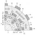
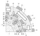
図7は、本発明の実施形態に係る回転電機の横断面図である。 FIG. 7 is a cross-sectional view of the rotary electric machine according to the embodiment of the present invention.
なお、図7は、回転電機1の1/4周、すなわち90度の領域の横断面図であるが、他の領域も同様の構造を有する。 Note that FIG. 7 is a cross-sectional view of a region of 1/4 circumference of the rotary
図1および図2に加えて図7に示すように、本実施形態に係る回転電機1のラジアルギャップロータ5は、ステータコア11に対面するラジアルギャップロータコア31と、ラジアルギャップロータコア31に設けられラジアルギャップロータコア31の周方向に等間隔で並ぶ複数のラジアルギャップロータティース32と、ラジアルギャップロータティース32のそれぞれに設けられる永久磁石33と、隣り合うラジアルギャップロータティース32の間に配置される磁路部材34と、磁路部材34に巻かれ誘導コイル23が誘起させた誘導電流が通電すると磁界を発生させる界磁コイル35と、を備えている。 As shown in FIG. 7 in addition to FIGS. 1 and 2, the
ラジアルギャップロータ3およびアキシャルギャップロータ5は、一体成形され、または回転軸6を介して組み合わされ、回転一体化されている。 The radial gap rotor 3 and the
複数、例えば8つのラジアルギャップロータティース32は、放射状に配置されている。ラジアルギャップロータティース32は、ラジアルギャップロータ5の径方向外側に向かって延びている。ラジアルギャップロータティース32は、高透磁率の磁性材料で製作されている。ラジアルギャップロータティース32とステータティース12との数量は異なる。したがって、ステータコア11とラジアルギャップロータ5とが相対的に回転するとき、ラジアルギャップロータティース32の外周面はステータティース12の内周面に適宜、近接し、対面する。 A plurality, for example, eight radial
隣り合う一対のラジアルギャップロータティース32は、ロータスロットを画定している。ロータスロットは、隣り合うラジアルギャップロータティース32の側面に挟まれる空間である。 A pair of adjacent radial gap lotus 32s define a rotor slot. The rotor slot is a space sandwiched between the side surfaces of adjacent radial
永久磁石33は、ラジアルギャップロータティース32に埋設されている。永久磁石33は、ラジアルギャップロータティース32毎に2つずつ配置されている。2つの永久磁石33は、一文字型に並んでいる。2つの永久磁石33の間には、ブリッジ部36が設けられている。なお、2つの永久磁石33は、V字型に配置されていても良い。 The
ラジアルギャップロータティース32は、永久磁石33よりもステータ2側に配置される先端部51を有している。先端部51は、永久磁石33と磁路部材34との間、および永久磁石33とステータティース12(第二ティース部16)との間に磁束を通す磁路である。先端部51は、ラジアルギャップロータティース32の突出端に相当する。ラジアルギャップロータティース32のうち、先端部51よりも根元側、つまり先端部51よりもステータ2から遠い側は、実質的に一様な幅寸法で延びている。先端部51は、ラジアルギャップロータ5の中心からの距離を半径とする円弧状の外周面を有している。また、先端部51は、永久磁石33よりも磁路部材34に向かって突出した形状を有している。具体的には、ラジアルギャップロータティース32の幅寸法よりも拡がってロータスロットに楔状に侵入する突出部51aを有している。 The radial
磁路部材34および界磁コイル35は、ロータスロットに配置されている。 The
磁路部材34は、高透磁率の磁性材料で製作されている。磁路部材34は、ラジアルギャップロータ5の回転中心と平行に延びている。磁路部材34は、隣り合う一対のラジアルギャップロータティース32の先端部51の間を短絡する磁路(以下、単に「磁路」または「バイパス磁路」と言う)を形成する。 The
磁路部材34は、界磁コイル35が巻かれる基部61と、隣り合う一対のラジアルギャップロータティース32のうち少なくとも一方の先端部51にむかって延びる突出部62と、を備えている。ラジアルギャップロータティース32の先端部51と磁路部材34の突出部62との間には、間隔G3が設けられている。 The
基部61は、界磁コイル35を巻き付けることが可能な板状の形状を有する。基部61は、ラジアルギャップロータ5の回転中心と平行に延び、かつ隣り合う一対のラジアルギャップロータティース32の間に架け渡されるように、ラジアルギャップロータ5の周方向に延びている。 The
突出部62は、基部61の周方向側の端部からラジアルギャップロータティース32の先端部51へ向かって延びている。 The projecting
ラジアルギャップロータティース32と磁路部材34との間隔G3は、ステータティース12(第二ティース部16)とラジアルギャップロータコア31との間隔G4よりも広い。間隔G3は、ラジアルギャップロータティース32の先端部51の突出部51aと、磁路部材34の突出部62との最短距離である。間隔G4は、ステータ2の第二ティース部16の最内周面と、ラジアルギャップロータティース32の先端部51の最外周面との最短距離であり、実質的にステータ2とラジアルギャップロータ5との隙間G2と同じである。 The distance G3 between the radial
ラジアルギャップロータティース32と磁路部材34との間隔G3を、隙間(空気)で隔てる場合、磁路部材34は、ラジアルギャップロータコア31の軸方向におけるそれぞれの端部でラジアルギャップロータコア31に固定される。ラジアルギャップロータティース32と磁路部材34との間隔G3は、隙間ではなく、非磁性体、例えば樹脂で満たされていても良い。この場合、磁路部材34は、間隔G3を埋める樹脂でラジアルギャップロータコア31に固定される。 When the distance G3 between the radial
永久磁石33は、隣り合う一対のラジアルギャップロータティース32においての磁極(N極、S極)を逆に向けて設置されている。換言すると、永久磁石33は、磁路部材34を挟んで隣り合うもの同士の極性が反対である。ラジアルギャップロータ5の全周においては、永久磁石33は、ラジアルギャップロータティース32毎に磁極(N極、S極)を交互に逆に向けて設置されている。ある1つのステータティース12(第二ティース部16)に着目すると、ラジアルギャップロータ5とステータ2とが相対回転するとき、永久磁石33のN極およびS極が、交互に繰り返しステータティース12(第二ティース部16)に対面する。 The
界磁コイル35は、磁路部材34の基部61に集中巻きされている。界磁コイル35は、隣り合う一対のラジアルギャップロータティース32の間で磁路を短絡させる向きに巻かれている。また、界磁コイル35は、ラジアルギャップロータ5の径方向に向かって巻かれている。磁路部材34毎に巻かれた界磁コイル35は、ラジアルギャップロータ5全体で直列に接続されている。なお、界磁コイル35は、並列接続しても良いし、別回路を設ける構造としても良い。 The
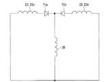
図8は、本発明の実施形態に係る回転電機の誘電コイルおよび界磁コイルの回路図である。 FIG. 8 is a circuit diagram of a coil and a field coil of a rotary electric machine according to an embodiment of the present invention.
図8に示すように、本実施形態に係る回転電機1は、誘導コイル23で発生する交流の誘導電流を直流の界磁電流にして界磁コイル35に供給する。回転電機1は、界磁コイル35に界磁電流を流し、磁路部材34を電磁石として機能させる。なお、誘導コイル23aは、例えばステータ2の軸方向の一方に配置されるアキシャルギャップロータ3の誘導コイル23であり、誘導コイル23bは、例えばステータ2の軸方向の他方に配置されるアキシャルギャップロータ3の誘導コイル23である。 As shown in FIG. 8, the rotary
誘導コイル23および界磁コイル35は、ダイオード71a、71bを介して接続されている。換言すると、誘導コイル23および界磁コイル35は、誘導回路および界磁回路として、外部の電源等の回路に接続されることのない閉回路内にダイオード71a、71bとともに組み込まれている。 The
この閉回路は、誘導コイル23で発生する交流の誘導電流を、ダイオード71a、71bを介して半波整流させて直流界磁電流に調整し、この後に合流させて界磁コイル35に供給する。 In this closed circuit, the AC induced current generated in the
ダイオード71a、71bは、それぞれ180度位相差になるように結線され、誘導コイル23の誘導電流を反転させて半波整流出力する中性点クランプ型の半波整流回路を構成している。 The
上述したとおり、回転電機1は、トロイダル集中巻されるステータ2と、ステータ2のアキシャル面に配置され誘導コイル23を有するアキシャルギャップロータ3と、ステータ2のラジアル面に配置され界磁コイル35を有するラジアルギャップロータ5と、を備えている。このように構成される回転電機1は、ステータ2の電機子コイル13に通電することにより磁束を発生させる。この磁束は、ステータティース12のラジアル面から対面するラジアルギャップロータティース32の先端部51の外周面に鎖交する。回転電機1は、ステータティース12とラジアルギャップロータティース32との間で鎖交する磁束の磁路を最短にしようとするリラクタンストルク、および永久磁石33の磁気反発力ならびに磁石吸引力によるマグネットトルクによってラジアルギャップロータ5を回転させる。そして、回転電機1は、ラジアルギャップロータ5と一体回転する回転軸6から機械的エネルギーを出力する。 As described above, the rotary
ところで、一般的な固定界磁形の永久磁石同期モータは、高回転で駆動するとき、永久磁石の磁束に起因する逆起電力(ステータ巻線誘導起電力、速度起電力とも言う)が増加する。そこで、逆起電力の電圧が電源電圧を超えないように、インバータを用いた電圧制限制御、いわゆる弱め磁束制御が行われる。この弱め磁束制御は、トルクに寄与しない磁束ベクトル方向に永久磁石の磁束を打ち消すベクトルを発生させる。したがって、弱め磁束制御は、モータの出力に寄与しない無駄なエネルギーを必要とし、効率を低下させる。また、弱め磁束制御は、ステータとロータとのギャップ中の磁束を大きく歪ませ、高調波成分を発生させ、鉄損を増加させ、電磁振動を増加させる。さらに、弱め磁束制御は、永久磁石に対向する逆磁界ベクトルを発生させて永久磁石の磁束を抑え込むため、比較的保磁力の高い磁石を必要とし、コストを増加させる。 By the way, in a general fixed field type permanent magnet synchronous motor, when driven at high speed, the counter electromotive force (also referred to as stator winding induced electromotive force or velocity electromotive force) due to the magnetic flux of the permanent magnet increases. .. Therefore, voltage limit control using an inverter, so-called weak magnetic flux control, is performed so that the voltage of the counter electromotive force does not exceed the power supply voltage. This weakening magnetic flux control generates a vector that cancels the magnetic flux of the permanent magnet in the direction of the magnetic flux vector that does not contribute to torque. Therefore, the weakening magnetic flux control requires wasted energy that does not contribute to the output of the motor, and reduces the efficiency. Further, the weak magnetic flux control greatly distorts the magnetic flux in the gap between the stator and the rotor, generates harmonic components, increases iron loss, and increases electromagnetic vibration. Further, the weakening magnetic flux control generates a reverse magnetic field vector facing the permanent magnet to suppress the magnetic flux of the permanent magnet, so that a magnet having a relatively high coercive force is required, which increases the cost.
本実施形態に係る回転電機1も、ステータティース12からラジアルギャップロータティース32に鎖交する磁束に高調波成分が重畳する。基本周波数の磁束に重畳する高調波成分は、基本周波数と異なる周期で時間的に変化しつつアキシャルギャップロータティース22にも鎖交する。 Also in the rotary
そこで、回転電機1は、ステータ2からアキシャルギャップロータ3に鎖交する磁束の高調波成分の磁束密度の変化を利用して、アキシャルギャップロータ3の誘導コイル23に誘導電流を発生させる。つまり、誘導コイル23は、第二次高調波成分を利用することによって、外部からの電力等を必要とすることなく、効率よく誘導電流を発生させる。この結果、回転電機1は、鉄損の原因となる高調波成分を自己励磁するためのエネルギーとして回収する。 Therefore, the rotary
図9および図10は、本発明の実施形態に係る回転電機の界磁コイルが生じさせる磁束の変化を概略的に示す図である。 9 and 10 are diagrams schematically showing changes in magnetic flux generated by the field coil of the rotary electric machine according to the embodiment of the present invention.
なお、図9および図10は、ラジアルギャップロータ5に生じる磁束を矢印で表し、ステータ2に生じる磁束を省略して図示している。 Note that FIGS. 9 and 10 show the magnetic flux generated in the
図9は、回転電機1が低速で回転しているときの様子を示し、図10は、回転電機1が高速で回転しているときの様子を示している。 FIG. 9 shows a state when the rotary
回転電機1は、誘導コイル23が発生させた誘導電流をダイオード71a、71bで整流し、この整流した誘導電流を界磁電流として界磁コイル35に流す。界磁コイル35は、界磁電流が流れることによって自己励磁し、磁路部材34、つまりバイパス磁路に磁極を形成する。誘導コイル23に発生する誘導起電力は、ファラデーの法則に基づき、回転電機1の回転速度の増加とともに増加する、つまり正の相関関係を有する。図9は回転電機1が低速で回転し誘導起電力が小さい状態を図示しているため、界磁電流(または界磁コイルの起電力)の図示を省略している。他方、図10は、回転電機1が低速で回転し誘導起電力が大きい状態を図示しているため、界磁電流(または界磁コイルの起電力)を図示している。誘導コイル23に発生する誘導起電力が回転電機1の回転速度の増加とともに増加するため、界磁コイル35は、回転電機1の回転速度の増加とともに磁路部材34の磁力を強め、隣り合うラジアルギャップロータティース32(32a、32b)に埋設される永久磁石33(33a、33b)の磁束をラジアルギャップロータ5内で短絡させ、ハルバッハ配列を形成する。この結果、回転電機1は、回転速度の変化に応じてステータ2に鎖交する磁束量を変化させる。換言すると、回転電機1は、回転速度の変化に応じてステータ2に鎖交する磁束量を可変させる。図9および図10は、磁路部材34の磁力による影響を矢印の太さで表している。回転電機1は、ステータ2に鎖交する磁束量を可変させるため、ステータ2に鎖交する磁束量を「φ」と表すとき、ステータ端子電圧V=電機子コイル巻数N×dφ/dtで表されるステータ端子電圧Vの増加を防ぐことができる。 The rotary
したがって、回転電機1は、ステータ2に鎖交する磁束量を制御し、ステータ端子電圧Vの増加を防ぎ、ひいては弱め界磁制御を不要にできる。また、回転電機1は、弱め界磁制御に起因するモータ電磁振動を大幅に低減させる。そして、回転電機1は、高回転時における出力を増加させ、効率を向上させる。 Therefore, the rotary
また、回転電機1は、回転速度の増加に応じて磁路部材34の磁力を強め、この磁力を永久磁石33の磁束の短絡に利用するため、誘導起電力が増加する高回転域で特に好適である。 Further, since the rotary
なお、アキシャルギャップロータ3およびラジアルギャップロータ5は、誘導コイル23と界磁コイル35とが電気的に接続されている限りにおいて、常に回転一体化されている必要はない。 The axial gap rotor 3 and the
次いで、本実施形態に係る回転電機1の他の例を説明する。なお、各例で説明する回転電機1A、1B、および1Cにおいて、図1から図10の回転電機1と同じ構成には同一の符号を付し、重複する説明は省略する。 Next, another example of the rotary
図11は、本発明の実施形態に係る回転電機の他の例の横断面図である。 FIG. 11 is a cross-sectional view of another example of the rotary electric machine according to the embodiment of the present invention.
図11に示すように、本実施形態に係る回転電機1Aは、ラジアルギャップロータ5の中心側から略一様な幅寸法で延びるラジアルギャップロータティース32Aと、磁路部材34Aと、を備えている。 As shown in FIG. 11, the rotary
ラジアルギャップロータティース32Aは、根元から突出端、つまり先端部51Aまでラジアルギャップロータ5の中心側から略一様な幅寸法で延びている。 The radial
磁路部材34Aは、誘導コイル23が巻かれる基部61と、隣り合う一対のラジアルギャップロータティース32Aの先端部51Aにむかって延びる突出部62Aと、を備えている。磁路部材34Aの突出部62Aは、図7における先端部51の突出部51aを兼ねている。 The
図12は、本発明の実施形態に係る回転電機の他の例の横断面図である。 FIG. 12 is a cross-sectional view of another example of the rotary electric machine according to the embodiment of the present invention.
図12に示すように、本実施形態に係る回転電機1Bは、ラジアルギャップロータティース32Bと、磁路部材34Bと、を備えている。 As shown in FIG. 12, the rotary
磁路部材34Bは、誘導コイル23が巻かれる基部61を有する。 The
ラジアルギャップロータティース32Bは、磁路部材34Bの基部61に向かって延びる先端部51Bを有している。ラジアルギャップロータティース32Bの先端部51Bは、図7における磁路部材34の突出部62を兼ねている。 The radial
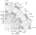
図13は、本発明の実施形態に係る回転電機の他の例の横断面図である。 FIG. 13 is a cross-sectional view of another example of the rotary electric machine according to the embodiment of the present invention.
図13に示すように、本実施形態に係る回転電機1Cは、ラジアルギャップロータ5の周方向において非対称なラジアルギャップロータティース32Cと、磁路部材34Cと、を備えている。 As shown in FIG. 13, the rotary electric machine 1C according to the present embodiment includes a radial gap rotor teeth 32C that is asymmetric in the circumferential direction of the
ラジアルギャップロータティース32Cは、ラジアルギャップロータ5の周方向においていずれか一方、図13では時計回りの方向に図11と同様な構造を有し、ラジアルギャップロータ5の周方向においていずれか他方、図13では反時計回りの方向に図12と同様な構造を有している。 The radial gap rotor teeth 32C has a structure similar to that in FIG. 11 in the clockwise direction in FIG. 13 while either one in the circumferential direction of the
磁路部材34Cは、ラジアルギャップロータ5の周方向においていずれか一方、図13では時計回りの方向に図12と同様な構造を有し、ラジアルギャップロータ5の周方向においていずれか他方、図13では反時計回りの方向に図11と同様な構造を有している。 The magnetic path member 34C has a structure similar to that in FIG. 12 in the clockwise direction in FIG. 13 while either one in the circumferential direction of the
ラジアルギャップロータティース32Cの時計回り方向の半分は、根元から突出端、つまり先端部51Cまでラジアルギャップロータ5の中心側から略一様な幅寸法で延びている。 The clockwise half of the radial gap rotor teeth 32C extends from the root to the protruding end, that is, the tip portion 51C from the central side of the
磁路部材34Cの反時計回り方向の半分は、誘導コイル23が巻かれる基部61と、隣り合う一対のラジアルギャップロータティース32Cの先端部51Cにむかって延びる突出部62Cと、を備えている。磁路部材34Cの突出部62Cは、図7における先端部51の突出部51aを兼ねている。 Half of the magnetic path member 34C in the counterclockwise direction includes a
磁路部材34Cの時計回りの半分は、誘導コイル23が巻かれる基部61を有する。 The clockwise half of the magnetic path member 34C has a
ラジアルギャップロータティース32Cの反時計回りの半分は、磁路部材34Cの基部61に向かって延びる先端部51Cを有している。ラジアルギャップロータティース32Cの先端部51Cは、図7における磁路部材34の突出部62を兼ねている。 The counterclockwise half of the radial gap rotor teeth 32C has a tip 51C extending toward the
図13の回転電機1Cは、図13における時計回りおよび反時計回りのいずれか一方にのみ回転させる場合に好適である。また、回転電機1Cは、正転と逆転との特性を変化させる場合にも好適である。 The rotary electric machine 1C of FIG. 13 is suitable for rotating only one of clockwise and counterclockwise in FIG. The rotary electric machine 1C is also suitable for changing the characteristics of forward rotation and reverse rotation.
このように構成される本実施形態に係る回転電機1、1A、1B、1Cは、誘導コイル23と界磁コイル35とを別々のロータ(すなわち、アキシャルギャップロータ3、ラジアルギャップロータ5)に巻いているため、従来の回転電機のように誘導コイル23と界磁コイル35とを同一のロータに巻く場合に比べてそれぞれのコイルを巻く領域をより大きく確保することができる。このことは、誘導コイル23および界磁コイル35それぞれの巻き数を増加させ、空間高調波の利用効率を高める。 In the rotary
また、本実施形態に係る回転電機1、1A、1B、1Cは、隣り合うラジアルギャップロータティース32、32A、32B、32Cの間に、永久磁石33の磁束のバイパス回路としての磁路部材34、34A、34B、34Cを配置しているため、ラジアルギャップロータティース32、32A、32B、32Cにフラックスバリアとしての空隙を設けてバイパス回路を形成する場合に比べ、永久磁石33を配置する場所を大きく確保することができる。なお、ラジアルギャップロータティース32、32A、32B、32Cにフラックスバリアを設けてバイパス回路を形成する場合には、より小さい永久磁石33を配置して界磁コイル35の配置場所を確保する代わりにより小さい永久磁石33を採用したり、同程度の大きさの永久磁石33を配置することでラジアルギャップロータティース32、32A、32B、32Cを周方向に幅広に確保する代わりに界磁コイル35の巻き数を減じたりしなければならなくなる。 Further, in the rotary
さらに、本実施形態に係る回転電機1、1A、1B、1Cは、界磁コイル35を磁路部材34、34A、34B、34Cに巻いているため、界磁コイル35を永久磁石に巻く場合に比べ、永久磁石の磁気抵抗がなく、界磁コイル35の磁束が通りやすく、効率的に磁束を発生させることができる。 Further, in the rotary
さらにまた、本実施形態に係る回転電機1、1A、1B、1Cは、ラジアルギャップロータティース32、32A、32B、32Cと磁路部材34、34A、34B、34Cとの間隔G3を有するため、磁路部材34、34A、34B、34Cに巻かれる界磁コイル35に生じる熱がラジアルギャップロータティース32、32A、32B、32Cに埋設される永久磁石33に伝わり難く、熱影響による永久磁石33の磁気特性の低下を防止できる。 Furthermore, since the rotary
また、本実施形態に係る回転電機1、1A、1B、1Cは、ラジアルギャップロータティース32、32A、32B、32Cと磁路部材34、34A、34B、34Cとの間隔G3が、ステータティース12とラジアルギャップロータコア31との間隔G4よりも広いため、ラジアルギャップロータティース32、32A、32B、32Cと磁路部材34、34A、34B、34Cとの間の磁気抵抗が、ステータコア11とラジアルギャップロータコア31との磁気抵抗よりも大きい。このことは、界磁コイル35に流れる界磁電流が少ない低回転時において、磁路部材34、34A、34B、34Cを介する永久磁石33間の磁束の短絡を減じ、トルクの低下を抑制する。 Further, in the rotary
さらに、本実施形態に係る回転電機1、1A、1B、1Cは、ラジアルギャップロータ5の径方向に向かって巻かれる界磁コイル35を備えているため、極数の多いロータ、つまりラジアルギャップロータティース32、32A、32B、32Cが多く、ロータスロットの幅が狭いラジアルギャップロータ5であっても、界磁コイル35の占積率を高めることができる。 Further, since the rotary
さらにまた、本実施形態に係る回転電機1、1A、1B、1Cは、永久磁石33と電磁石になった磁路部材34、34A、34B、34Cとがハルバッハ配列になるため、界磁コイル35の磁束を永久磁石33の磁束に作用させやすい。 Furthermore, in the rotary
また、本実施形態に係る回転電機1、1A、1Cは、誘導コイル23が巻かれる基部61から隣接する一対のラジアルギャップロータティース32、32A、32Cのうち少なくとも一方の先端部51にむかって延びる突出部62、62A、62Cを有する磁路部材34、34A、34Cを備えることによって、界磁コイル35の配置の自由度を高めることができる。磁路部材34、34A、34Cは、ロータスロットの径方向における略中央に基部61を配置することで界磁コイル35の占積率を高めることができる。このとき、磁路部材34、34A、34Cの基部61とラジアルギャップロータティース32、32A、32Cの先端部51、51A、51Cとは、ラジアルギャップロータ5の径方向に離間してしまうことになる。そこで、回転電機1、1B、1Cは、磁路部材34、34B、34Cに突出部62を設けることによって、基部61とラジアルギャップロータティース32、32A、32Cの先端部51、51A、51Cとの離間距離、すなわち間隔G3を容易に調整することができる。 Further, the rotary
さらに、本実施形態に係る回転電機1、1B、1Cは、ラジアルギャップロータティース32、32B、32Cに永久磁石33よりも磁路部材34、34B、34Cに向かって突出した形状を有する先端部51、51B、51Cを有することによって、永久磁石33の磁束を磁束線に沿ったバイパス磁路に容易に形成できる。 Further, the rotary
図14は、本発明の実施形態に係る回転電機の他の例の横断面図である。 FIG. 14 is a cross-sectional view of another example of the rotary electric machine according to the embodiment of the present invention.
なお、本実施形態に係る回転電機1、1A、1B、1Cは、図1から図13のようなステータ2の内側にラジアルギャップロータ5を配置するインナーロータ型に限られず、図14に示すように、ステータ2の外側にラジアルギャップロータ5を配置するアウターロータ型であっても良い。 The rotary
この場合、回転電機1、1A、1B、1Cは、筒状のステータ2と、ステータ2の軸方向の少なくともいずれか一方に配置され、隙間G1を隔ててステータ2に対面するアキシャルギャップロータ3と、ステータ2の径方向外側に配置され、隙間G2を隔ててステータ2に対面するラジアルギャップロータ5と、を備えることになる。ステータ2の第二ティース部16は、第一ティース部15の外側の形状に整合してステータコア11の中心線に向かって狭まる台形状を有している。第二ティース部16は、ステータコア11の外周面を長手方向、つまりステータコア11の中心線に平行な方向へ延びている。ラジアルギャップロータティース32は、ラジアルギャップロータ5の径方向内側に向かって延びている。 In this case, the rotary
また、本実施形態に係る回転電機1、1A、1B、1Cは、非磁性部材21に代えて、または非磁性部材21とは別に、アキシャルギャップロータティース22と同一材料で形成されるアキシャルギャップロータコアを備えていても良い。この場合、アキシャルギャップロータコアとアキシャルギャップロータティース22とを一体形成でき、製造コストおよび製造工数を低減することができる。 Further, the rotary
また、本実施形態に係る回転電機1、1A、1B、1Cは、アキシャルギャップロータ3の非磁性部材21および誘導コイル23と、ラジアルギャップロータ5のラジアルギャップロータコア31、界磁コイル35、永久磁石33、および磁路部材34とを入れ替えても良い。つまり、回転電機1、1A、1B、1Cのラジアルギャップロータ5は、非磁性部材21、ステータコア11に対面し周方向に等間隔で並ぶ複数のラジアルギャップロータティース32と、ラジアルギャップロータティース32に巻かれステータ2で発生する磁束に基づいて誘導電流を誘起させる誘導コイル23と、を有し、アキシャルギャップロータ3は、ステータコア11に対面するアキシャルギャップロータコア21と、アキシャルギャップロータコア21に設けられアキシャルギャップロータコア21の周方向に等間隔で並ぶ複数のアキシャルギャップロータティース22と、アキシャルギャップロータティース22のそれぞれに設けられる永久磁石33と、隣り合うアキシャルギャップロータティース22の間に配置される磁路部材34と、磁路部材34に巻かれ誘導コイル23が誘起させた誘導電流が流れると磁界を発生させる界磁コイル35と、を有するものであっても良い。この場合においても、本実施形態に係る回転電機1、1A、1B、1Cは、非磁性部材21に代えて、または非磁性部材21とは別に、アキシャルギャップロータティース22と同一材料で形成されるアキシャルギャップロータコアを設けても良い。 Further, the rotary
図15は、本発明の実施形態に係る回転電機の他の例の界磁コイルが生じさせる磁束の変化を概略的に示す図である。 FIG. 15 is a diagram schematically showing a change in magnetic flux generated by a field coil of another example of a rotary electric machine according to an embodiment of the present invention.
さらに、本実施形態に係る回転電機1、1A、1B、1Cは、図10のように界磁コイル35の起磁力を、電機子コイル13および永久磁石33の磁束を弱める方向に利用するものに限られない。インバータの電源電圧に制約がなければ、本実施形態に係る回転電機1、1A、1B、1Cは、図15に示すように従来技術のように、界磁コイル35の起磁力を、電機子コイル13および永久磁石33の磁束を強める方向に利用しても良い。この場合、界磁コイル35は、図10の場合の反対方向に巻かれる。 Further, the rotary
さらにまた、本実施形態に係る回転電機1、1A、1B、1Cは、誘導コイル23と界磁コイル35とをアキシャルギャップロータ3とラジアルギャップロータ5とに分けて配置するものに限られない。本実施形態に係る回転電機1、1A、1B、1Cは、誘導コイル23と界磁コイル35とを兼用するコイルを、アキシャルギャップロータ3およびラジアルギャップロータ5のそれぞれに設けても良い。この場合、本実施形態に係る回転電機1、1A、1B、1Cは、誘導コイル23および界磁コイル35を兼用するコイルを別々のロータ(すなわち、アキシャルギャップロータ3、ラジアルギャップロータ5)に巻いているため、従来の回転電機のように誘導コイル23と界磁コイル35とを同一のロータに巻く場合に比べてそれぞれのコイルを巻く領域をより大きく確保することができる。 Furthermore, the rotary
また、本実施形態に係る回転電機1、1A、1B、1Cは、外部からアキシャルギャップロータ3およびラジアルギャップロータ5にエネルギーを入力する必要のない構造を有し、例えば、ハイブリッド自動車や電気自動車に搭載することが好適な性能を有している。 Further, the rotary
したがって、本発明に係る回転電機1、1A、1B、1Cによれば、誘導コイル23および界磁コイル35の巻き数を確保し易く、ひいては空間高調波成分をより効率的に利用することができる。 Therefore, according to the rotary
1、1A、1B、1C…回転電機、2…ステータ、3…アキシャルギャップロータ、5…ラジアルギャップロータ、6…回転軸、7…ケーシング、11…ステータコア、12…ステータティース、13、13a、13b、13c…電機子コイル、15…第一ティース部、16…第二ティース部、21…非磁性部材、22…アキシャルギャップロータティース、23、23a、23b…誘導コイル、31…ラジアルギャップロータコア、32、32A、32B、32C、32a、32b…ラジアルギャップロータティース、33、33a、33b…永久磁石、34、34A、34B、34C…磁路部材、35…界磁コイル、35…界磁コイル、36…ブリッジ部、51、51A、51B、51C…先端部、51a…突出部、61…基部、62、62A、62C…突出部、71a、71b…ダイオード。 1, 1A, 1B, 1C ... Rotating armature, 2 ... Stator, 3 ... Axial gap rotor, 5 ... Radial gap rotor, 6 ... Rotating shaft, 7 ... Casing, 11 ... Stator core, 12 ... Stator teeth, 13, 13a, 13b , 13c ... armature coil, 15 ... first teeth part, 16 ... second teeth part, 21 ... non-magnetic member, 22 ... axial gap rotor teeth, 23, 23a, 23b ... induction coil, 31 ... radial gap rotor core, 32. , 32A, 32B, 32C, 32a, 32b ... Radial Gap Rotates, 33, 33a, 33b ... Permanent magnets, 34, 34A, 34B, 34C ... Magnetic path members, 35 ... Field coil, 35 ... Field coil, 36 ... Bridge, 51, 51A, 51B, 51C ... Tip, 51a ... Projection, 61 ... Base, 62, 62A, 62C ... Projection, 71a, 71b ... Diode.
Claims (6)
Translated fromJapanese前記ステータの軸方向の少なくともいずれか一方に配置され隙間を隔てて前記ステータに対面するアキシャルギャップロータと、
前記ステータの径方向内側または外側に配置され隙間を隔てて前記ステータに対面するラジアルギャップロータと、を備え、
前記ステータは、
ステータコアと、
前記ステータコアに設けられ前記ステータコアの周方向に等間隔で並ぶ複数のステータティースと、
前記ステータコアまたは前記ステータティースに巻かれる電機子コイルと、を有し、
前記アキシャルギャップロータは、
前記ステータコアに対面し前記アキシャルギャップロータコアの周方向に等間隔で並ぶ複数のアキシャルギャップロータティースと、
前記アキシャルギャップロータティースに巻かれ前記ステータで発生する磁束に基づいて誘導電流を誘起させる誘導コイルと、を有し、
前記ラジアルギャップロータは、
前記ステータコアに対面するラジアルギャップロータコアと、
前記ラジアルギャップロータコアに設けられ前記ラジアルギャップロータコアの周方向に等間隔で並ぶ複数のラジアルギャップロータティースと、
前記ラジアルギャップロータティースのそれぞれに設けられる永久磁石と、
隣り合う前記ラジアルギャップロータティースの間に配置される磁路部材と、
前記磁路部材に巻かれ前記誘導電流が流れると磁界を発生させる界磁コイルと、を有し、
前記ラジアルギャップロータティースは、前記永久磁石よりも前記ステータ側に配置され前記永久磁石と前記磁路部材との間、および前記永久磁石と前記ステータティースとの間に磁束を通す磁路としての先端部を有する回転電機。With a tubular stator
An axial gap rotor that is arranged in at least one of the axial directions of the stator and faces the stator with a gap.
A radial gap rotor that is arranged radially inside or outside the stator and faces the stator with a gap is provided.
The stator is
With the stator core
A plurality of stator teeth provided on the stator core and arranged at equal intervals in the circumferential direction of the stator core,
It has an armature coil that is wound around the stator core or the stator teeth.
The axial gap rotor is
A plurality of axial gap rotor teeth facing the stator core and arranged at equal intervals in the circumferential direction of the axial gap rotor core.
It has an induction coil that is wound around the axial gap rotor and induces an induced current based on a magnetic flux generated in the stator.
The radial gap rotor is
The radial gap rotor core facing the stator core and
A plurality of radial gap rotor tires provided on the radial gap rotor core and arranged at equal intervals in the circumferential direction of the radial gap rotor core,
Permanent magnets provided in each of the radial gap rotors,
A magnetic path member arranged between the adjacent radial gap rotors,
Have a, a field coil for generating a magnetic field when the induced current wound around the magnetic path memberflows,
The radial gap rotor tooth is arranged on the stator side of the permanent magnet and is a tip as a magnetic path through which magnetic flux is passed between the permanent magnet and the magnetic path member and between the permanent magnet and the stator teeth. rotating electric machine tohave a part.
前記磁路部材は、前記誘導コイルが巻き付けられる基部と、隣接する一対の前記ラジアルギャップロータティースのうち少なくとも一方の前記先端部にむかって延びる突出部と、を有している請求項3に記載の回転電機。Before SL permanent magnets are of opposite polarity and adjacent groups across the magnetic path member,
The third aspect of claim 3, wherein the magnetic path member has a base around which the induction coil is wound and a protruding portion extending toward the tip of at least one of the pair of adjacent radial gap rotors. Rotating electric machine.
前記ステータの軸方向の少なくともいずれか一方に配置され隙間を隔てて前記ステータに対面するアキシャルギャップロータと、
前記ステータの径方向内側または外側に配置され隙間を隔てて前記ステータに対面するラジアルギャップロータと、を備え、
前記ステータは、
ステータコアと、
前記ステータコアに設けられ前記ステータコアの周方向に等間隔で並ぶ複数のステータティースと、
前記ステータコアまたは前記ステータティースに巻かれる電機子コイルと、を有し、
前記ラジアルギャップロータは、
前記ステータコアに対面すし周方向に等間隔で並ぶ複数のラジアルギャップロータティースと、
前記ラジアルギャップロータティースに巻かれ前記ステータで発生する磁束に基づいて誘導電流を誘起させる誘導コイルと、を有し、
前記アキシャルギャップロータは、
前記ステータコアに対面するアキシャルギャップロータコアと、
前記アキシャルギャップロータコアに設けられ前記アキシャルギャップロータコアの周方向に等間隔で並ぶ複数のアキシャルギャップロータティースと、
前記アキシャルギャップロータティースのそれぞれに設けられる永久磁石と、
隣り合う前記アキシャルギャップロータティースの間に配置される磁路部材と、
前記磁路部材に巻かれ前記誘導電流が流れると磁界を発生させる界磁コイルと、を有する回転電機。With a tubular stator
An axial gap rotor that is arranged in at least one of the axial directions of the stator and faces the stator with a gap.
A radial gap rotor that is arranged radially inside or outside the stator and faces the stator with a gap is provided.
The stator is
With the stator core
A plurality of stator teeth provided on the stator core and arranged at equal intervals in the circumferential direction of the stator core,
It has an armature coil that is wound around the stator core or the stator teeth.
The radial gap rotor is
A plurality of radial gap rotors arranged at equal intervals in the circumferential direction facing the stator core,
It has an induction coil that is wound around the radial gap rotor and induces an induced current based on the magnetic flux generated by the stator.
The axial gap rotor is
The axial gap rotor core facing the stator core and
A plurality of axial gap rotor teeth provided on the axial gap rotor core and arranged at equal intervals in the circumferential direction of the axial gap rotor core.
Permanent magnets provided in each of the axial gap rotors,
A magnetic path member arranged between the adjacent axial gap rotor teeth,
A rotary electric machine having a field coil that is wound around the magnetic path member and generates a magnetic field when the induced current flows.
Priority Applications (1)
| Application Number | Priority Date | Filing Date | Title |
|---|---|---|---|
| JP2016198335AJP6766574B2 (en) | 2016-10-06 | 2016-10-06 | Rotating electric machine |
Applications Claiming Priority (1)
| Application Number | Priority Date | Filing Date | Title |
|---|---|---|---|
| JP2016198335AJP6766574B2 (en) | 2016-10-06 | 2016-10-06 | Rotating electric machine |
Publications (2)
| Publication Number | Publication Date |
|---|---|
| JP2018061378A JP2018061378A (en) | 2018-04-12 |
| JP6766574B2true JP6766574B2 (en) | 2020-10-14 |
Family
ID=61910079
Family Applications (1)
| Application Number | Title | Priority Date | Filing Date |
|---|---|---|---|
| JP2016198335AActiveJP6766574B2 (en) | 2016-10-06 | 2016-10-06 | Rotating electric machine |
Country Status (1)
| Country | Link |
|---|---|
| JP (1) | JP6766574B2 (en) |
Cited By (1)
| Publication number | Priority date | Publication date | Assignee | Title |
|---|---|---|---|---|
| WO2025011692A1 (en)* | 2023-07-11 | 2025-01-16 | Schaeffler Technologies AG & Co. KG | Rotor for an electric machine formed in individual segments |
Families Citing this family (2)
| Publication number | Priority date | Publication date | Assignee | Title |
|---|---|---|---|---|
| US11482894B2 (en) | 2020-10-15 | 2022-10-25 | Mitsubishi Electric Research Laboratories, Inc. | Electric machine with combined axial- and radial-flux |
| CN115065178B (en)* | 2022-06-06 | 2024-06-11 | 河北工业大学 | Integrated two-module magnetic flux reversing motor of vehicle-mounted charger |
Family Cites Families (5)
| Publication number | Priority date | Publication date | Assignee | Title |
|---|---|---|---|---|
| DE102013102900A1 (en)* | 2013-03-21 | 2014-09-25 | Feaam Gmbh | synchronous machine |
| JP6303311B2 (en)* | 2013-07-23 | 2018-04-04 | スズキ株式会社 | Synchronous reluctance motor |
| JP6326938B2 (en)* | 2014-04-24 | 2018-05-23 | スズキ株式会社 | Electric rotating machine |
| JP6332011B2 (en)* | 2014-12-22 | 2018-05-30 | スズキ株式会社 | Axial gap type rotating electrical machine |
| JP6507721B2 (en)* | 2015-03-05 | 2019-05-08 | スズキ株式会社 | Electric rotating machine and current input control method of electric rotating machine |
- 2016
- 2016-10-06JPJP2016198335Apatent/JP6766574B2/enactiveActive
Cited By (1)
| Publication number | Priority date | Publication date | Assignee | Title |
|---|---|---|---|---|
| WO2025011692A1 (en)* | 2023-07-11 | 2025-01-16 | Schaeffler Technologies AG & Co. KG | Rotor for an electric machine formed in individual segments |
Also Published As
| Publication number | Publication date |
|---|---|
| JP2018061378A (en) | 2018-04-12 |
Similar Documents
| Publication | Publication Date | Title |
|---|---|---|
| JP5491484B2 (en) | Switched reluctance motor | |
| US9006949B2 (en) | Synchronous motor | |
| JP5302527B2 (en) | Rotating electric machine and drive control device thereof | |
| JP6668844B2 (en) | Rotating electric machine | |
| JP6589624B2 (en) | motor | |
| JP6561692B2 (en) | Rotating electric machine | |
| US20150091403A1 (en) | Transverse flux machine and vehicle | |
| JP2011078202A (en) | Axial gap motor | |
| JP6569396B2 (en) | Rotating electric machine | |
| CN107078617B (en) | Double stator type rotator | |
| JP6766575B2 (en) | Rotating electric machine | |
| JP6760014B2 (en) | Rotating electric machine | |
| JPWO2019187205A1 (en) | Rotating machine | |
| JP6592525B2 (en) | Magnet rotor, rotating electric machine including magnet rotor, and electric vehicle including rotating electric machine | |
| JP6766574B2 (en) | Rotating electric machine | |
| WO2018051938A1 (en) | Rotating electrical machine | |
| JP6645351B2 (en) | Rotating electric machine | |
| WO2018143377A1 (en) | Dynamo-electric machine | |
| JP6260994B2 (en) | Axial gap type motor | |
| JP6589703B2 (en) | Rotating electric machine | |
| CN110391701B (en) | Rotating electrical machine | |
| JP6476920B2 (en) | Rotating electric machine | |
| JP6485073B2 (en) | Rotating electric machine | |
| JP2014007787A (en) | Rotary electric machine and system for driving rotary electric machine | |
| JP6965677B2 (en) | Rotating machine and rotating machine system |
Legal Events
| Date | Code | Title | Description |
|---|---|---|---|
| A621 | Written request for application examination | Free format text:JAPANESE INTERMEDIATE CODE: A621 Effective date:20190627 | |
| A977 | Report on retrieval | Free format text:JAPANESE INTERMEDIATE CODE: A971007 Effective date:20200527 | |
| A131 | Notification of reasons for refusal | Free format text:JAPANESE INTERMEDIATE CODE: A131 Effective date:20200609 | |
| A521 | Written amendment | Free format text:JAPANESE INTERMEDIATE CODE: A523 Effective date:20200730 | |
| TRDD | Decision of grant or rejection written | ||
| A01 | Written decision to grant a patent or to grant a registration (utility model) | Free format text:JAPANESE INTERMEDIATE CODE: A01 Effective date:20200818 | |
| A61 | First payment of annual fees (during grant procedure) | Free format text:JAPANESE INTERMEDIATE CODE: A61 Effective date:20200831 | |
| R151 | Written notification of patent or utility model registration | Ref document number:6766574 Country of ref document:JP Free format text:JAPANESE INTERMEDIATE CODE: R151 |