JP6763042B2 - Roof rail and how to install the roof rail - Google Patents
Roof rail and how to install the roof railDownload PDFInfo
- Publication number
- JP6763042B2 JP6763042B2JP2019029609AJP2019029609AJP6763042B2JP 6763042 B2JP6763042 B2JP 6763042B2JP 2019029609 AJP2019029609 AJP 2019029609AJP 2019029609 AJP2019029609 AJP 2019029609AJP 6763042 B2JP6763042 B2JP 6763042B2
- Authority
- JP
- Japan
- Prior art keywords
- base member
- roof
- roof rail
- wall portion
- fastening
- Prior art date
- Legal status (The legal status is an assumption and is not a legal conclusion. Google has not performed a legal analysis and makes no representation as to the accuracy of the status listed.)
- Expired - Fee Related
Links
- 238000000034methodMethods0.000claimsdescription6
- 239000000463materialSubstances0.000description3
- 238000005553drillingMethods0.000description2
- 238000012986modificationMethods0.000description2
- 230000004048modificationEffects0.000description2
- XAGFODPZIPBFFR-UHFFFAOYSA-NaluminiumChemical compound[Al]XAGFODPZIPBFFR-UHFFFAOYSA-N0.000description1
- 229910052782aluminiumInorganic materials0.000description1
- 239000011347resinSubstances0.000description1
- 229920005989resinPolymers0.000description1
Images


Landscapes
- Fittings On The Vehicle Exterior For Carrying Loads, And Devices For Holding Or Mounting Articles (AREA)
Description
Translated fromJapanese本発明は、自動車のルーフに取り付けられるルーフレール、およびルーフレールの取り付け方法に関するものである。 The present invention relates to a roof rail to be attached to the roof of an automobile and a method of attaching the roof rail.
ルーフレールを自動車のルーフに取り付けるために、ルーフレールブラケットをルーフの内側から挿通させたボルトによって締め付ける技術が知られている(例えば、特許文献1参照。)。 In order to attach the roof rail to the roof of an automobile, there is known a technique of tightening the roof rail bracket with a bolt inserted from the inside of the roof (see, for example, Patent Document 1).
しかしながら、ボルトをルーフの内側から挿通させて締め付けるためには、作業者が車体の内部に入り、車体の内側から締め付け作業をする必要がある。すなわち、車体内に出入りする動作を必要とするため、作業性を向上させることが困難であった。 However, in order to insert the bolt from the inside of the roof and tighten it, it is necessary for the operator to enter the inside of the vehicle body and perform the tightening work from the inside of the vehicle body. That is, it is difficult to improve workability because it requires an operation of entering and exiting the vehicle body.
本発明は、上記の点に鑑み、ルーフレールを取り付けるための作業性を容易に向上させられるようにすることを目的としている。 In view of the above points, it is an object of the present invention to make it possible to easily improve the workability for attaching the roof rail.
上記の目的を達成するため、本発明は、
自動車のルーフに取り付けられるルーフレールであって、
上壁部と下壁部とを有し、ルーフ上に取り付けられるベース部材と、
上記ベース部材の上方を覆うように設けられるアウター部材と、
を備え、
上記ベース部材の下壁部には、上記ベース部材をルーフに取り付ける締結部材を挿通させる締結部材孔が形成され、
上記ベース部材の上壁部には、上記下壁部の締結部材孔の上方位置に、締結作業工具を挿入可能な開口部が形成されるとともに、上記アウター部材に形成され、または上記アウター部材に取り付けられた係合部材に形成された係合部が係合する被係合部が形成されていることを特徴とする。In order to achieve the above object, the present invention
A roof rail that can be attached to the roof of an automobile
A base member that has an upper wall part and a lower wall part and is mounted on the roof,
An outer member provided so as to cover the upper part of the base member and
With
In the lower wall portion of the base member, a fastening member hole through which the fastening member for attaching the base member to the roof is inserted is formed.
In the upper wall portion of the base member, an opening into which a fastening work tool can be inserted is formed at a position above the fastening member hole of the lower wall portion, and is formed in the outer member or in the outer member. It is characterized in that an engaged portion is formed to engage the engaging portion formed on the attached engaging member.
これにより、ルーフレールをベース部材とアウター部材とによって構成し、ベース部材を車体の上方側からボルト締め等可能にすることによって、車体内に出入りする動作などを不要にできるので、ルーフレールの取り付け作業の作業性を容易に向上させることができる。また、ボルトを締め付ける等のための開口部などは、アウター部材によって覆うことができるので、デザイン性を向上させることなども容易になる。 As a result, the roof rail is composed of a base member and an outer member, and the base member can be bolted from the upper side of the vehicle body, so that the operation of entering and exiting the vehicle body can be eliminated. Workability can be easily improved. Further, since the opening for tightening the bolt or the like can be covered with the outer member, it becomes easy to improve the design.
本発明によれば、ルーフレールを取り付けるための作業性を容易に向上させることができる。 According to the present invention, the workability for attaching the roof rail can be easily improved.
以下、本発明の実施形態を図面に基づいて詳細に説明する。なお、以下の実施形態や変形例において、同様の機能を有する構成要素については同一の符号を付して説明を省略する。 Hereinafter, embodiments of the present invention will be described in detail with reference to the drawings. In the following embodiments and modifications, components having similar functions are designated by the same reference numerals and description thereof will be omitted.
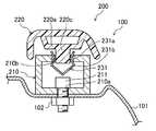
図1に示すように、自動車100のルーフ101に取り付けられるルーフレール200は、ベース部材210と、このベース部材210を覆うように設けられるアウター部材220とを備えて構成されている。 As shown in FIG. 1, the
上記ベース部材210は、図2、図3に示すように、上壁部と下壁部とを有する断面角管形状を有し、下壁部に形成されたボルト孔210aに車体上方側から挿通されるボルト211が、ルーフ101の内面側に取り付けられたナット102に螺合することによって固定されるようになっている。ベース部材210の上壁部には、後述するようにアウター部材220をベース部材210に固定するための係合部材221が係合する被係合部210bが形成されている。このベース部材210の材質は種々適用可能であるが、例えばアルミニウムの押し出し材などを用いることができる。 As shown in FIGS. 2 and 3, the
アウター部材220は、例えば略逆U字型の断面形状を有する樹脂によって形成され、ベース部材210の上部を覆ってデザイン性等を高め得るようになっている。アウター部材220の下面側には、所定の距離を空けて壁部220aが形成され、この壁部220aには、係合部材221が取り付けられる略U字型の係合部材取付凹部220bが形成されている。 The
係合部材221は、頭部221aと首部221bとフランジ部221cとを有し、上記首部221bが上記アウター部材220の壁部220aの係合部材取付凹部220bに嵌まり込むとともに、頭部221aとフランジ部221cがアウター部材220の壁部220aを挟み込むことによって、アウター部材220に固定され得るようになっている。係合部材221の下部には、上方に折り返した切片状の係合部221dが形成され、ベース部材210の上壁部に形成された上記被係合部210bに挿入されることによって係止され、アウター部材220をベース部材210に固定し得るようになっている。 The
ここで、上記ベース部材210の上壁部に形成される被係合部210bは、下壁部に形成されるボルト孔210aと上下方向に同じ位置に配置され、係合部材221を係止する機能を有するとともに、ボルト211、およびこのボルト211を締め付けるための六角レンチを上方から挿入可能な開口部としても用いられるようになっている。なお、係合部材221を係止するための被係合部210bとボルト211の締め付け等を行うための開口部は別個に形成してもよいが、同じ位置に形成することにより、アウター部材220に作用する外力をボルト211の締結部で受けやすくすることができ、ルーフレール200の取り付け強度や剛性を向上させることが容易にできる。また、孔開け加工の工数を低減することもできる。また、ボルト孔210aと被係合部210bとを、ボルト211のボルト頭よりも大径かつ互いに同径の孔として形成し、ボルト211のボルト頭と下壁部との間にワッシャを用いるようにしたりしてもよい。この場合には、ボルト孔210aと被係合部210bとを同時に形成することが容易になるので、一層、孔開け加工の工数を低減することも容易になる。 Here, the engaged
上記のようにルーフレール200をベース部材210とアウター部材220とによって構成し、ベース部材210を車体の上方側からボルト締め可能にすることによって、車体内に出入りする動作などを不要にできるので、ルーフレール200の取り付け作業の作業性を容易に向上させることができる。また、ボルト211を締め付けるための開口部などは、ベース部材210をルーフ101に取り付けた後にアウター部材220を取り付けることによって覆うことができるので、例えばホールプラグを用いたりする必要もない上、さらに、アウター部材220の材質の自由度を高くして、デザイン性を向上させることなども容易になる。 As described above, the
(変形例)
ベース部材210とアウター部材220との固定方法は上記に限らず、種々の手法を適用してもよい。例えば上記のような係合部材221をアウター部材220に取り付けるのに限らず、係合部材221と同様の係合部をアウター部材220に直接形成したりしてもよい。(Modification example)
The method of fixing the
また、例えば、図4に示すように、アウター部材220の壁部220aの下面側に凸部220cを形成し、板ばね等の弾性板を括れ部231aと張出部231bとを有する形状に折り曲げ加工した係合部材231を上記凸部220cに被せて、ベース部材210の上壁部に形成された例えば角形の被係合部210bに挿入して、アウター部材220をベース部材210に固定し得るようにしたりしてもよい。 Further, for example, as shown in FIG. 4, a
また、ベース部材210をルーフ101に取り付けるための部材はボルト211に限らず、例えば、上方からかしめ作業をすることによってベース部材210とルーフ101とを締結可能なかしめ締結部材など、上方から締結作業工具によって取り付け作業が可能な締結部材であればよく、被係合部210b等の開口部は、上記工具による作業が可能な開口部であればよい。 Further, the member for attaching the
100 自動車
101 ルーフ
102 ナット
200 ルーフレール
210 ベース部材
210a ボルト孔
210b 被係合部
211 ボルト
220 アウター部材
220a 壁部
220b 係合部材取付凹部
220c 凸部
221 係合部材
221a 頭部
221b 首部
221c フランジ部
221d 係合部
231 係合部材
231a 括れ部
231b 張出部
100
Claims (4)
Translated fromJapanese上壁部と下壁部とを有し、ルーフ上に取り付けられるベース部材と、
上記ベース部材の上方を覆うように設けられるアウター部材と、
を備え、
上記ベース部材の下壁部には、上記ベース部材をルーフに取り付ける締結部材を挿通させる締結部材孔が形成され、
上記ベース部材の上壁部には、上記下壁部の締結部材孔の上方位置に、締結作業工具を挿入可能な開口部が形成されるとともに、上記アウター部材に形成され、または上記アウター部材に取り付けられた係合部材に形成された係合部が係合する被係合部が形成され、
上記開口部は、独立した孔であることを特徴とするルーフレール。A roof rail that can be attached to the roof of an automobile
A base member that has an upper wall part and a lower wall part and is mounted on the roof,
An outer member provided so as to cover the upper part of the base member and
With
In the lower wall portion of the base member, a fastening member hole through which the fastening member for attaching the base member to the roof is inserted is formed.
In the upper wall portion of the base member, an opening into which a fastening work tool can be inserted is formed at a position above the fastening member hole of the lower wall portion, and is formed in the outer member or in the outer member. An engaged portion is formed in which the engaging portion formed on the attached engaging member engages.
The opening is a roof rail characterizedby being an independent hole .
上記ベース部材の上壁部の開口部が、上記被係合部を兼ねることを特徴とするルーフレール。The roof rail of claim 1.
A roof rail characterized in that the opening of the upper wall portion of the base member also serves as the engaged portion.
上記ベース部材の下壁部の締結部材孔と、上記ベース部材の上壁部の開口部とは、同径の孔であることを特徴とするルーフレール。The roof rail according to any one of claims 1 to 2.
A roof rail characterized in that the fastening member hole of the lower wall portion of the base member and the opening of the upper wall portion of the base member have holes having the same diameter.
上記ベース部材を上記ルーフに載置し、上記締結部材孔に上方から挿入した締結部材の締結作業により上記ルーフに取り付ける工程と、
上記ベース部材の被係合部に上記係合部を係合させて上記アウター部材を上記ベース部材に取り付ける工程と、
を有することを特徴とするルーフレールの取り付け方法。A method of attaching a roof rail to attach the roof rail according to any one of claims 1 to 3 to the roof of an automobile.
A step of placing the base member on the roof and attaching the base member to the roof by fastening the fastening member inserted into the fastening member hole from above.
A step of engaging the engaging portion with the engaged portion of the base member and attaching the outer member to the base member.
A method of mounting a roof rail, which comprises having.
Priority Applications (1)
| Application Number | Priority Date | Filing Date | Title |
|---|---|---|---|
| JP2019029609AJP6763042B2 (en) | 2019-02-21 | 2019-02-21 | Roof rail and how to install the roof rail |
Applications Claiming Priority (1)
| Application Number | Priority Date | Filing Date | Title |
|---|---|---|---|
| JP2019029609AJP6763042B2 (en) | 2019-02-21 | 2019-02-21 | Roof rail and how to install the roof rail |
Publications (2)
| Publication Number | Publication Date |
|---|---|
| JP2020132010A JP2020132010A (en) | 2020-08-31 |
| JP6763042B2true JP6763042B2 (en) | 2020-09-30 |
Family
ID=72277600
Family Applications (1)
| Application Number | Title | Priority Date | Filing Date |
|---|---|---|---|
| JP2019029609AExpired - Fee RelatedJP6763042B2 (en) | 2019-02-21 | 2019-02-21 | Roof rail and how to install the roof rail |
Country Status (1)
| Country | Link |
|---|---|
| JP (1) | JP6763042B2 (en) |
Family Cites Families (4)
| Publication number | Priority date | Publication date | Assignee | Title |
|---|---|---|---|---|
| US4432478A (en)* | 1981-05-04 | 1984-02-21 | Bott John Anthony | Vehicle article carrier |
| AU601188B2 (en)* | 1986-06-16 | 1990-09-06 | Huron/St. Clair Company. | Load-bearing slat for vehicle luggage carriers |
| DE4313526A1 (en)* | 1993-04-24 | 1994-10-27 | Happich Gmbh Gebr | Roof rails for vehicles |
| JP2004203123A (en)* | 2002-12-24 | 2004-07-22 | Aisin Seiki Co Ltd | Roof rack |
- 2019
- 2019-02-21JPJP2019029609Apatent/JP6763042B2/ennot_activeExpired - Fee Related
Also Published As
| Publication number | Publication date |
|---|---|
| JP2020132010A (en) | 2020-08-31 |
Similar Documents
| Publication | Publication Date | Title |
|---|---|---|
| US5269640A (en) | Holding device for use in assembling mechanical members | |
| CN101153622A (en) | Ornament mounting structure for vehicles | |
| KR101582895B1 (en) | Fixture for vehicle | |
| JP6763042B2 (en) | Roof rail and how to install the roof rail | |
| JP6939454B2 (en) | Engine mounting structure | |
| JP5214310B2 (en) | Deck side trim mounting structure | |
| JP4283136B2 (en) | Fixed structure, protector and electrical junction box | |
| KR101582898B1 (en) | Fixture for vehicle | |
| KR102540927B1 (en) | Vehicle clip | |
| JPH0530679U (en) | Piping clamp mounting structure | |
| JP4021821B2 (en) | Door striker mounting structure | |
| KR200467331Y1 (en) | Mounting-nut unit | |
| KR101314109B1 (en) | Grommet | |
| KR100569360B1 (en) | Installation structure of speed sensor assembly for automobile | |
| JP3952987B2 (en) | Overfender mounting structure | |
| JP2009280004A (en) | Fastening structure for hollow member | |
| JP3846701B2 (en) | Non-rotating structure for mounting parts | |
| KR200408990Y1 (en) | Wiring Harness Waterproof Grommet Structure | |
| JP5354285B2 (en) | Bumper holder mounting structure | |
| KR100700046B1 (en) | Wiring Harness Waterproof Grommet Structure | |
| JPH06179337A (en) | Cap for rail of seat slide | |
| KR200250461Y1 (en) | Bracket for automobile | |
| JPH0120423Y2 (en) | ||
| JPH0550139U (en) | bolt | |
| JPS6035828Y2 (en) | Piping fixing structure in automobiles |
Legal Events
| Date | Code | Title | Description |
|---|---|---|---|
| A621 | Written request for application examination | Free format text:JAPANESE INTERMEDIATE CODE: A621 Effective date:20190221 | |
| A977 | Report on retrieval | Free format text:JAPANESE INTERMEDIATE CODE: A971007 Effective date:20191223 | |
| A131 | Notification of reasons for refusal | Free format text:JAPANESE INTERMEDIATE CODE: A131 Effective date:20200107 | |
| A521 | Request for written amendment filed | Free format text:JAPANESE INTERMEDIATE CODE: A523 Effective date:20200309 | |
| TRDD | Decision of grant or rejection written | ||
| A01 | Written decision to grant a patent or to grant a registration (utility model) | Free format text:JAPANESE INTERMEDIATE CODE: A01 Effective date:20200901 | |
| A61 | First payment of annual fees (during grant procedure) | Free format text:JAPANESE INTERMEDIATE CODE: A61 Effective date:20200909 | |
| R150 | Certificate of patent or registration of utility model | Ref document number:6763042 Country of ref document:JP Free format text:JAPANESE INTERMEDIATE CODE: R150 | |
| LAPS | Cancellation because of no payment of annual fees |