JP6762285B2 - Protector for wire harness and manufacturing method of wire harness - Google Patents
Protector for wire harness and manufacturing method of wire harnessDownload PDFInfo
- Publication number
- JP6762285B2 JP6762285B2JP2017203713AJP2017203713AJP6762285B2JP 6762285 B2JP6762285 B2JP 6762285B2JP 2017203713 AJP2017203713 AJP 2017203713AJP 2017203713 AJP2017203713 AJP 2017203713AJP 6762285 B2JP6762285 B2JP 6762285B2
- Authority
- JP
- Japan
- Prior art keywords
- path
- cover
- main body
- cover portion
- protector
- Prior art date
- Legal status (The legal status is an assumption and is not a legal conclusion. Google has not performed a legal analysis and makes no representation as to the accuracy of the status listed.)
- Active
Links
Images


Classifications
- H—ELECTRICITY
- H02—GENERATION; CONVERSION OR DISTRIBUTION OF ELECTRIC POWER
- H02G—INSTALLATION OF ELECTRIC CABLES OR LINES, OR OF COMBINED OPTICAL AND ELECTRIC CABLES OR LINES
- H02G3/00—Installations of electric cables or lines or protective tubing therefor in or on buildings, equivalent structures or vehicles
- H02G3/02—Details
- H02G3/04—Protective tubing or conduits, e.g. cable ladders or cable troughs
- H02G3/0406—Details thereof
- H02G3/0418—Covers or lids; Their fastenings
- B—PERFORMING OPERATIONS; TRANSPORTING
- B60—VEHICLES IN GENERAL
- B60R—VEHICLES, VEHICLE FITTINGS, OR VEHICLE PARTS, NOT OTHERWISE PROVIDED FOR
- B60R16/00—Electric or fluid circuits specially adapted for vehicles and not otherwise provided for; Arrangement of elements of electric or fluid circuits specially adapted for vehicles and not otherwise provided for
- B60R16/02—Electric or fluid circuits specially adapted for vehicles and not otherwise provided for; Arrangement of elements of electric or fluid circuits specially adapted for vehicles and not otherwise provided for electric constitutive elements
- B60R16/0207—Wire harnesses
- B60R16/0215—Protecting, fastening and routing means therefor
- H—ELECTRICITY
- H01—ELECTRIC ELEMENTS
- H01B—CABLES; CONDUCTORS; INSULATORS; SELECTION OF MATERIALS FOR THEIR CONDUCTIVE, INSULATING OR DIELECTRIC PROPERTIES
- H01B7/00—Insulated conductors or cables characterised by their form
- H01B7/0045—Cable-harnesses
- H—ELECTRICITY
- H02—GENERATION; CONVERSION OR DISTRIBUTION OF ELECTRIC POWER
- H02G—INSTALLATION OF ELECTRIC CABLES OR LINES, OR OF COMBINED OPTICAL AND ELECTRIC CABLES OR LINES
- H02G1/00—Methods or apparatus specially adapted for installing, maintaining, repairing or dismantling electric cables or lines
- H02G1/06—Methods or apparatus specially adapted for installing, maintaining, repairing or dismantling electric cables or lines for laying cables, e.g. laying apparatus on vehicle
- H02G1/08—Methods or apparatus specially adapted for installing, maintaining, repairing or dismantling electric cables or lines for laying cables, e.g. laying apparatus on vehicle through tubing or conduit, e.g. rod or draw wire for pushing or pulling
- H—ELECTRICITY
- H02—GENERATION; CONVERSION OR DISTRIBUTION OF ELECTRIC POWER
- H02G—INSTALLATION OF ELECTRIC CABLES OR LINES, OR OF COMBINED OPTICAL AND ELECTRIC CABLES OR LINES
- H02G3/00—Installations of electric cables or lines or protective tubing therefor in or on buildings, equivalent structures or vehicles
- H02G3/02—Details
- H02G3/04—Protective tubing or conduits, e.g. cable ladders or cable troughs
- H02G3/0437—Channels
- H—ELECTRICITY
- H02—GENERATION; CONVERSION OR DISTRIBUTION OF ELECTRIC POWER
- H02G—INSTALLATION OF ELECTRIC CABLES OR LINES, OR OF COMBINED OPTICAL AND ELECTRIC CABLES OR LINES
- H02G3/00—Installations of electric cables or lines or protective tubing therefor in or on buildings, equivalent structures or vehicles
- H02G3/02—Details
- H02G3/04—Protective tubing or conduits, e.g. cable ladders or cable troughs
- H02G3/0462—Tubings, i.e. having a closed section
- H02G3/0468—Corrugated
- H—ELECTRICITY
- H02—GENERATION; CONVERSION OR DISTRIBUTION OF ELECTRIC POWER
- H02G—INSTALLATION OF ELECTRIC CABLES OR LINES, OR OF COMBINED OPTICAL AND ELECTRIC CABLES OR LINES
- H02G3/00—Installations of electric cables or lines or protective tubing therefor in or on buildings, equivalent structures or vehicles
- H02G3/02—Details
- H02G3/04—Protective tubing or conduits, e.g. cable ladders or cable troughs
- H02G3/0462—Tubings, i.e. having a closed section
- H02G3/0487—Tubings, i.e. having a closed section with a non-circular cross-section
Landscapes
- Engineering & Computer Science (AREA)
- Architecture (AREA)
- Civil Engineering (AREA)
- Structural Engineering (AREA)
- Mechanical Engineering (AREA)
- Details Of Indoor Wiring (AREA)
- Insulated Conductors (AREA)
- Protection Of Pipes Against Damage, Friction, And Corrosion (AREA)
Description
Translated fromJapanese本発明は、ワイヤハーネスを構成する電線に対して組み付けられるプロテクタ、及び、プロテクタが電線に組み付けられたワイヤハーネスの製造方法、に関する。 The present invention relates to a protector attached to an electric wire constituting a wire harness, and a method for manufacturing a wire harness in which the protector is attached to the electric wire.
従来から、ワイヤハーネスを構成する電線を収容可能な経路(空洞・空間)を内部に画成するワイヤハーネス用プロテクタが提案されている。この種のプロテクタは、例えば、その内部に収容した電線を保護すると共に、ワイヤハーネスを自動車の車体等に配索する際の固定具として用いられる。 Conventionally, a protector for a wire harness has been proposed in which a path (cavity / space) capable of accommodating an electric wire constituting the wire harness is defined inside. This type of protector is used, for example, as a fixture for protecting an electric wire housed therein and for arranging a wire harness to a vehicle body or the like of an automobile.
従来のプロテクタの一つは、底壁と両側壁とを有する断面U字状の溝(みぞ)構造を有し且つ立体的形状を有するプロテクタ本体と、プロテクタ本体の開口部を覆うカバーと、を備える。この従来のプロテクタでは、プロテクタ本体の底壁と両側壁が画成する経路内に電線を収容した後、プロテクタ本体にカバーを取り付けて固定することにより、電線を経路内に収容するようになっている(例えば、特許文献1を参照。)。 One of the conventional protectors has a protector body having a U-shaped cross-section groove structure having a bottom wall and both side walls and having a three-dimensional shape, and a cover covering the opening of the protector body. Be prepared. In this conventional protector, the electric wire is accommodated in the path defined by the bottom wall and both side walls of the protector body, and then the electric wire is accommodated in the path by attaching a cover to the protector body and fixing the electric wire. (See, for example, Patent Document 1).
上述した従来のプロテクタは、その両端部において電線をプロテクタ本体に対してテープ巻きによって固定し、更にその中央部において電線を押え片によってプロテクタ本体の中に押し込んだ状態にて、プロテクタ本体にカバーを取り付けるようになっている。このような取り付け手順により、従来のプロテクタは、プロテクタ本体が立体的な形状を有する場合であっても、プロテクタ本体から電線が離れた(浮き上がった)状態でカバーが取り付けられてプロテクタ本体とカバーとの間に電線が挟まれることを抑制するようになっている。 In the conventional protector described above, the electric wire is fixed to the protector main body by tape winding at both ends thereof, and the electric wire is further pushed into the protector main body by a holding piece at the central portion thereof, and then the cover is attached to the protector main body. It is designed to be installed. By such an attachment procedure, in the conventional protector, even when the protector main body has a three-dimensional shape, the cover is attached with the electric wire separated (floating) from the protector main body, and the protector main body and the cover are attached. It is designed to prevent the electric wire from being caught between the two.
しかし、実際には、この従来のプロテクタを電線に取り付ける際、電線をプロテクタ本体に対してテープ巻きによって固定する必要があるため、電線にプロテクタを取り付ける作業の効率を向上させにくい。更に、そのように電線にプロテクタを取り付けた後、種々の事情によって電線からプロテクタを取り外すこととなった際、電線とプロテクタとに巻き付けられたテープを取り除く必要があるため、電線からプロテクタを取り外す作業も困難である。 However, in reality, when attaching this conventional protector to an electric wire, it is necessary to fix the electric wire to the protector body by winding a tape, so that it is difficult to improve the efficiency of the work of attaching the protector to the electric wire. Furthermore, after attaching the protector to the electric wire in this way, when the protector is removed from the electric wire due to various circumstances, it is necessary to remove the tape wrapped around the electric wire and the protector, so the work of removing the protector from the electric wire. Is also difficult.
本発明は、上述した事情に鑑みてなされたものであり、その目的は、ワイヤハーネスを構成する電線に対してプロテクタを組み付ける際の作業性に優れたワイヤハーネス用のプロテクタ、及び、ワイヤハーネスの製造方法、を提供することにある。 The present invention has been made in view of the above circumstances, and an object of the present invention is to provide a protector for a wire harness having excellent workability when assembling a protector to an electric wire constituting the wire harness, and a wire harness. The manufacturing method is to provide.
前述した目的を達成するために、本発明に係る「ワイヤハーネス用のプロテクタ」は、下記(1)〜(3)を特徴としている。
(1)
ワイヤハーネスを構成する電線が通過可能な経路を画成する本体部と、前記電線を前記経路の中に保持するための複数のカバー部と、を備えた、ワイヤハーネス用のプロテクタであって、
前記本体部は、
前記経路に沿って延び且つ該本体部への前記ワイヤハーネスの組付方向に窪んだ溝によって前記経路を画成すると共に、前記経路の一端、前記経路の他端、及び、前記一端と前記他端との間の前記経路の中間箇所のうちの一つが、他の二つに比べて前記組付方向において異なる位置に前記溝の底部を有し、前記経路の一端を一端として直線状に延びる第1部分と、前記経路の他端を一端として直線状に延びる第2部分と、前記第2部分の他端から前記第2部分の延在方向と交差する方向に直線状に延びて前記中間箇所を通る第3部分と、前記第1部分の他端と前記第3部分の他端とを直線状に連結し且つ前記第1部分及び前記第3部分の双方の延在方向と交差する方向に延びる第4部分と、を含む、立体的形状を有し、
前記複数のカバー部は、
前記第1部分及び前記第4部分にて前記溝の開口を覆って前記電線を保持する第1カバー部と、前記第2部分にて前記開口を覆って前記電線を保持する第2カバー部と、前記第1カバー部に相対変位可能に繋がると共に前記第3部分にて前記開口を覆って前記電線を保持する第3カバー部と、を有する、
ワイヤハーネス用のプロテクタであること。
(2)
上記(1)に記載のプロテクタにおいて、
前記第1カバー部は、
前記本体部の前記第1部分に相対変位可能に繋がり、
前記第2カバー部は、
前記本体部の前記第2部分に相対変位可能に繋がる、
ワイヤハーネス用のプロテクタであること。
(3)
上記(1)又は上記(2)に記載のプロテクタにおいて、
前記本体部は、
前記電線の外周を覆うように装着されるコルゲートチューブを前記経路の軸線方向において相対移動不能に係止する係止突起を、前記経路の少なくとも一部に有する、
ワイヤハーネス用のプロテクタであること。In order to achieve the above-mentioned object, the "protector for a wire harness" according to the present invention is characterized by the following (1) to (3).
(1)
A protector for a wire harness, comprising a main body portion that defines a path through which an electric wire constituting the wire harness can pass, and a plurality of cover portions for holding the electric wire in the path.
The main body
The path is defined by a groove extending along the path and recessed in the assembling direction of the wire harness to the main body, and one end of the path, the other end of the path, and the one end and the other. one of the intermediate portion of the path between the end, thehave a bottom of the groove at different positions in the assembly direction than the other two,extends in a straight line one end of the route as part The first portion, the second portion extending linearly with the other end of the path as one end, and the intermediate extending linearly from the other end of the second portion in a direction intersecting the extending direction of the second portion. A direction in which the third portion passing through the portion, the other end of the first portion, and the other end of the third portion are linearly connected and intersect with the extending directions of both the first portion and the third portion. Has a three-dimensional shape,including a fourth portion extending into
The plurality of cover portions
A first cover portion for holdingsaid first portion and said electric wire covering the opening of the groove inthe fourth portion, and a second cover portion for holding the electric wire covering the opening insaid second portion A third cover portionthat is connectedto the first cover portion so asto be relatively displaceable and that covers the opening and holds the electric wire atthe third portion .
Must be a protector for wire harnesses.
(2)
In the protector described in (1) above
The first cover portion is
It is connected tothe first part ofthe main body so as to be relatively displaceable.
The second cover portion is
It is connected tothe second part ofthe main body so as to be relatively displaceable.
Must be a protector for wire harnesses.
(3)
In the protector described in (1) or (2) above,
The main body
At least a part of the path has a locking projection that locks the corrugated tube mounted so as to cover the outer periphery of the electric wire so as to be relatively immovable in the axial direction of the path.
Must be a protector for wire harnesses.
上記(1)の構成のプロテクタによれば、プロテクタが画成する経路(組付方向に窪んだ溝)にワイヤハーネスを構成する電線を収容した後、第1カバー部および第2カバー部によって経路の一端と他端とに対応する部分(溝の開口)を覆うことにより、経路の両端において電線が本体部から離れる(浮き上がる)ことが抑制される。更に、本体部が立体的形状を有することから特に電線の離れが生じ易い経路の中間箇所に対応する部分を、第3カバー部によって覆うことにより、経路の中間箇所においても電線が本体部から離れることが抑制される。 According to the protector having the configuration of (1) above, after accommodating the electric wires constituting the wire harness in the path defined by the protector (groove recessed in the assembly direction), the path is taken by the first cover portion and the second cover portion. By covering the portions (groove openings) corresponding to one end and the other end of the path, it is possible to prevent the electric wire from being separated (floating) from the main body at both ends of the path. Further, since the main body has a three-dimensional shape, the portion corresponding to the intermediate portion of the path where the electric wire is likely to be separated is covered with the third cover portion, so that the electric wire is separated from the main body even at the intermediate portion of the path. Is suppressed.
ここで、第3カバー部は、第1カバー部および第2カバー部の一方に相対変位可能に(例えば、ヒンジを中心として回動可能に)繋がっているため、第1カバー部および第2カバー部によって経路の両端に対応する部分を覆う作業と、第3カバー部によって経路の中間箇所に対応する部分を覆う作業と、を滞りなく連続して実行できる。例えば、第1カバーに第3カバーが繋がっている場合、作業者は、第1カバー及び第2カバーを本体部に取り付けた後、第1カバーから手を離すことなく速やかに第3カバーを本体部に取り付けることができる。第2カバーに第3カバーが繋がっている場合も同様である。 Here, since the third cover portion is connected to one of the first cover portion and the second cover portion so as to be relatively displaceable (for example, rotatably about the hinge), the first cover portion and the second cover portion are connected. The work of covering the portions corresponding to both ends of the route by the portions and the work of covering the portions corresponding to the intermediate portions of the route by the third cover portion can be continuously executed without delay. For example, when the third cover is connected to the first cover, the operator can quickly attach the third cover to the main body without taking his / her hand off the first cover after attaching the first cover and the second cover to the main body. Can be attached to the part. The same applies when the third cover is connected to the second cover.
したがって、本構成のプロテクタによれば、上述した従来のプロテクタのようなテープ巻きも押え片による固定も要さないため、ワイヤハーネスを構成する電線に対してプロテクタを組み付ける際の作業性を向上できる。更に、仮に電線からプロテクタを取り外すことになった場合であっても、本体から複数のカバー部を取り外すだけでよいため、従来のプロテクタのようにテープを用いる場合に比べ、電線からプロテクタを取り外す作業も容易である。 Therefore, according to the protector having this configuration, unlike the conventional protector described above, neither tape winding nor fixing with a holding piece is required, so that workability when assembling the protector to the electric wire constituting the wire harness can be improved. .. Furthermore, even if the protector is to be removed from the electric wire, it is only necessary to remove a plurality of cover parts from the main body, so that the work of removing the protector from the electric wire is different from the case of using tape as in the conventional protector. Is also easy.
上記(2)の構成のプロテクタによれば、第1カバー部および第2カバー部が本体部に相対変位可能に(例えば、ヒンジを中心として回動可能に)繋がっている。そのため、例えば、作業者は、本体部の経路に電線を収容した後、本体部から手を離すことなく速やかに第1カバー部および第2カバー部を変位させ(例えば、ヒンジを中心に回動させる)、経路の両端に対応する部分(溝の開口)を覆うことができる。よって、第1カバー部および第2カバー部が本体部から独立した部品である場合に比べ、プロテクタを組み付ける作業性を更に向上できる。 According to the protector having the configuration of (2) above, the first cover portion and the second cover portion are connected to the main body portion so as to be relatively displaceable (for example, rotatably around a hinge). Therefore, for example, after accommodating the electric wire in the path of the main body portion, the operator quickly displaces the first cover portion and the second cover portion (for example, rotates around the hinge) without taking his / her hand off the main body portion. It is possible to cover the parts (groove openings) corresponding to both ends of the path. Therefore, the workability for assembling the protector can be further improved as compared with the case where the first cover portion and the second cover portion are independent parts from the main body portion.
上記(3)の構成のプロテクタによれば、電線の外周を覆うようにコルゲートチューブが装着されている場合、本体部に設けた係止突起によってコルゲートチューブを係止することにより、コルゲートチューブ及び電線が経路の軸線方向に移動すること(経路の軸線方向における位置ズレ)を抑制できる。 According to the protector having the configuration of (3) above, when the corrugated tube is mounted so as to cover the outer circumference of the electric wire, the corrugated tube and the electric wire are locked by locking the corrugated tube with a locking projection provided on the main body. Can be suppressed from moving in the axial direction of the route (positional deviation in the axial direction of the route).
例えば、係止突起を第1カバー部および第2カバー部に対応する位置に設ければ、第1カバー部および第2カバー部によって経路の両端に対応する部分を覆ったとき、それら部分においてコルゲートチューブを固定できる。これにより、経路の両端にて、コルゲートチューブ及び電線の位置ズレを抑制できる。その結果、例えば、第1カバー部および第2カバー部を本体部に取り付けた後、電線が本体部の外部から内部に向けて押し込まれて経路の中間箇所において電線が経路から離れる(浮き上がる)こと等を抑制できる。よって、プロテクタを組み付ける作業性を更に向上できる。 For example, if the locking projections are provided at positions corresponding to the first cover portion and the second cover portion, when the first cover portion and the second cover portion cover the portions corresponding to both ends of the path, the corrugated portions thereof. The tube can be fixed. As a result, misalignment of the corrugated tube and the electric wire can be suppressed at both ends of the path. As a result, for example, after the first cover portion and the second cover portion are attached to the main body portion, the electric wire is pushed inward from the outside of the main body portion, and the electric wire separates (floats) from the path at an intermediate portion of the path. Etc. can be suppressed. Therefore, the workability of assembling the protector can be further improved.
更に、前述した目的を達成するために、本発明に係る「ワイヤハーネスの製造方法」は、下記(4)を特徴としている。
(4)
ワイヤハーネスを構成する電線に対してプロテクタが組み付けられたワイヤハーネスの製造方法であって、
前記プロテクタは、
前記電線が通過可能な経路を画成する本体部であって、前記経路に沿って延び且つ該本体部への前記ワイヤハーネスの組付方向に窪んだ溝によって前記経路を画成すると共に、前記経路の一端、前記経路の他端、及び、前記一端と前記他端との間の前記経路の中間箇所のうちの一つが、他の二つに比べて前記組付方向において異なる位置に前記溝の底部を有し、前記経路の一端を一端として直線状に延びる第1部分と、前記経路の他端を一端として直線状に延びる第2部分と、前記第2部分の他端から前記第2部分の延在方向と交差する方向に直線状に延びて前記中間箇所を通る第3部分と、前記第1部分の他端と前記第3部分の他端とを直線状に連結し且つ前記第1部分及び前記第3部分の双方の延在方向と交差する方向に延びる第4部分と、を含む、立体的形状を有する、本体部と、
前記電線を前記経路の中に保持するための複数のカバー部であって、前記第1部分及び前記第4部分にて前記溝の開口を覆って前記電線を保持する第1カバー部と、前記第2部分にて前記開口を覆って前記電線を保持する第2カバー部と、前記第1カバー部に相対変位可能に繋がると共に前記第3部分にて前記開口を覆って前記電線を保持する第3カバー部と、を含む、複数のカバー部と、を有し、
該製造方法は、
前記複数のカバー部によって前記開口が覆われていない状態にて、前記経路の中に前記電線を収容する工程と、
前記第1カバー部によって前記第1部分及び前記第4部分の前記開口を覆うように、前記第1カバー部を前記本体部に組み付ける工程と、
前記第2カバー部によって前記第2部分の前記開口を覆うように、前記第2カバー部を前記本体部に組み付ける工程と、
前記第1カバー部及び前記第2カバー部を前記本体部に組み付けた後、前記第3カバー部によって前記第3部分の前記開口を覆うように、前記第3カバー部を前記本体部に組み付ける工程と、を備えた、
ワイヤハーネスの製造方法であること。Further, in order to achieve the above-mentioned object, the "method for manufacturing a wire harness" according to the present invention is characterized by the following (4).
(4)
A method of manufacturing a wire harness in which a protector is attached to the electric wires that make up the wire harness.
The protector is
A main body portion that defines a path through which the electric wire can pass, and the path is defined by a groove extending along the path and recessed in the assembling direction of the wire harness to the main body portion, and the path is defined. One end of the path, the other end of the path, and one of the intermediate points of the path between the one end and the other end are located at different positions in the assembly direction as compared with the other two. the bottomhave a,a first portion extending in a straight line one end of the route as part, and a second portion extending in a straight line as part of the other end of the path, the second from the other end of the second portion A third portion that extends linearly in a direction intersecting the extending direction of the portion and passes through the intermediate portion, and the other end of the first portion and the other end of the third portion are linearly connected and said to be the first. A body portion having a three-dimensional shape,including a fourth portion extending in a direction intersecting the extending direction of both the first portion and the third portion .
A plurality of cover portions for holding the wire in said path, a first cover portion for holding the electric wire covering the opening of said groove insaid first portion and said fourth portion,said A second cover portion that covers the opening and holds the electric wire in the second portion and a second cover portion thatis relatively displaceably connectedto the first cover portionand that covers the opening and holds the electric wire inthe third portion . It has a plurality of cover parts including three cover parts,
The manufacturing method is
A step of accommodating the electric wire in the path in a state where the opening is not covered by the plurality of cover portions.
A step of assembling the first cover portion to the main body portion so that the first cover portion covers theopenings ofthe first portion and the fourth portion .
A step of assembling the second cover portion to the main body portion so that the second cover portion covers theopening of the second portion .
A step of assembling the first cover portion and the second cover portion to the main body portion, and then assembling the third cover portion to the main body portion so that the third cover portion covers theopening of the third portion. And equipped with
It must be a wire harness manufacturing method.
上記(4)の構成の製造方法によれば、プロテクタが画成する経路(組付方向に窪んだ溝)にワイヤハーネスを構成する電線を収容する工程の後、第1カバー部および第2カバー部によって経路の一端と他端とに対応する部分(溝の開口)を覆う工程を経て、経路の両端において電線が本体部から離れる(浮き上がる)ことが抑制される。更に、これら工程の後、本体部が立体的形状を有することから特に電線の離れが生じ易い中間箇所に対応する部分を第3カバー部によって覆う工程を経て、経路の中間箇所においても電線が本体部から離れることが抑制される。 According to the manufacturing method of the configuration (4) above, after the step of accommodating the electric wires constituting the wire harness in the path defined by the protector (groove recessed in the assembly direction), the first cover portion and the second cover Through the step of covering the portion (groove opening) corresponding to one end and the other end of the path by the portion, the electric wire is suppressed from being separated (floating) from the main body portion at both ends of the path. Further, after these steps, since the main body has a three-dimensional shape, the electric wire is covered with the third cover portion in the intermediate portion where the electric wire is likely to be separated. Separation from the part is suppressed.
ここで、第3カバー部は、第1カバー部および第2カバー部の一方に相対変位可能に(例えば、ヒンジを中心として回動可能に)繋がっているため、第1カバー部および第2カバー部によって経路の両端に対応する部分を覆う工程と、第3カバー部によって経路の中間箇所に対応する部分を覆う工程と、を滞りなく連続して実行できる。 Here, since the third cover portion is connected to one of the first cover portion and the second cover portion so as to be relatively displaceable (for example, rotatably about the hinge), the first cover portion and the second cover portion are connected. The step of covering the portions corresponding to both ends of the route by the portions and the step of covering the portions corresponding to the intermediate portions of the route by the third cover portion can be continuously executed without delay.
したがって、本構成のワイヤハーネスの製造方法によれば、ワイヤハーネスを構成する電線に対してプロテクタを組み付ける際の作業性を向上できる。更に、この製造方法によって製造されたワイヤハーネスによれば、仮に電線からプロテクタを取り外すこととなった場合であっても、本体から複数のカバー部を取り外すだけでよいため、従来のプロテクタのようにテープを用いる場合に比べ、電線からプロテクタを取り外す作業も容易である。 Therefore, according to the method for manufacturing a wire harness having this configuration, workability when assembling the protector to the electric wire constituting the wire harness can be improved. Further, according to the wire harness manufactured by this manufacturing method, even if the protector is to be removed from the electric wire, it is only necessary to remove a plurality of cover portions from the main body, so that the protector can be removed like a conventional protector. It is easier to remove the protector from the wire than when using tape.
本発明によれば、ワイヤハーネスを構成する電線に対してプロテクタを組み付ける際の作業性に優れたワイヤハーネス用のプロテクタ、及び、ワイヤハーネスの製造方法、を提供できる。 According to the present invention, it is possible to provide a protector for a wire harness having excellent workability when assembling the protector to an electric wire constituting the wire harness, and a method for manufacturing the wire harness.
以上、本発明について簡潔に説明した。更に、以下に説明される発明を実施するための形態(以下、「実施形態」という。)を添付の図面を参照して通読することにより、本発明の詳細は更に明確化されるであろう。 The present invention has been briefly described above. Further, the details of the present invention will be further clarified by reading through the embodiments for carrying out the invention described below (hereinafter, referred to as "embodiments") with reference to the accompanying drawings. ..
<実施形態>
以下、図面を参照しながら、本発明の実施形態に係るワイヤハーネス用のプロテクタ1、及び、ワイヤハーネスWHの製造方法について説明する。プロテクタ1は、ワイヤハーネスWHを構成する電線束Wの軸線方向の一部に取り付けられ、典型的には、車両の車体フレーム等の所定箇所に固定される。これにより、ワイヤハーネスWHが車体に配索されることになる。<Embodiment>
Hereinafter, the
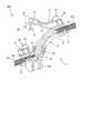
図1及び図2に示すように、プロテクタ1は、本体部2と、カバー部3と、を備える。カバー部3は、第1カバー部4、第2カバー部5、及び、第3カバー部6を含む。本体部2及びカバー部3は、合成樹脂から形成されている。 As shown in FIGS. 1 and 2, the
先ず、本体部2について説明する。本体部2は、上方に開口する(一対の上縁部を有する)断面U字状の長尺状の部材であり、ワイヤハーネスWHを構成する電線束W(図3等を参照)が通過可能な1本の連続した経路11(U字状溝)を画成している(図2(a)を参照)。このように、経路11は、本体部2へのワイヤハーネスWHの組付方向(上下方向)において窪んだ溝によって画成されている。 First, the
本体部2は、経路11の一端12、経路11の他端13、及び、一端12と他端13との間の経路11の中間箇所14のうちの一つが、他の二つに比べてプロテクタ1の上下方向(ワイヤハーネスWHの組付方向)において異なる位置にあるような、立体的形状を有している。本例では、上下方向において、他端13と中間箇所14とがほぼ同じ位置にあり、一端12が中間箇所14に対して大きく上方に移動した位置にある。 In the
本体部2の一端12側の端部における一対の上縁部のうち一方側には、経路11に沿う方向に延びる第1ヒンジ部15を介して、第1カバー部4が回動可能に連結されている(図2(a)を参照)。一方、本体部2の他端13側の端部における一対の上縁部のうち一方側には、経路11に沿う方向に延びる第2ヒンジ部16を介して、第2カバー部5が回動可能に連結されている。第1カバー部4及び第2カバー部5のそれぞれは、閉位置(図1を参照)と開位置(図2を参照)との間を個別に移動可能となっている。 A
本体部2の第1ヒンジ部15が形成された箇所における一対の上縁部のうち他方側には、幅方向に僅かに突出形成された枠体部にて、上下方向に貫通する係止孔17が設けられている。係止孔17は、第1カバー部4の係止片32を挿入するために設けられている。 On the other side of the pair of upper edge portions in the portion where the
同様に、本体部2の第2ヒンジ部16が形成された箇所における一対の上縁部のうち他方側には、幅方向に僅かに突出形成された枠体部にて、係止孔18が設けられている(図1(a)を参照)。係止孔18は、第2カバー部5の係止片41を挿入するために設けられている。 Similarly, on the other side of the pair of upper edge portions at the portion where the
本体部2の中間箇所14における一対の上縁部には、幅方向に僅かに突出形成された一対の枠体部にて、上下方向に貫通する一対の係止孔19が設けられている。一対の係止孔19は、第3カバー部6の一対の係止片51を挿入するために設けられている。 A pair of upper edge portions at an
本体部2の第1ヒンジ部15及び係止孔17が形成された箇所、及び、第2ヒンジ部16及び係止孔18が形成された箇所にはそれぞれ、経路11(U字状溝)の内部に突出する係止突起群21(複数の係止突起22,23)が設けられている(図2(a)を参照)。係止突起群21は、ワイヤハーネスWHを構成する電線束Wの外周を覆うコルゲートチューブCC(図3等を参照)を、経路11の軸線方向において相対移動不能に係止するために設けられている。 A path 11 (U-shaped groove) is provided at a location where the
図2(b)に拡大して示すように、係止突起群21としては、一対の係止突起22と、一対の係止突起23とが設けられている。一対の係止突起22は、経路11の軸線方向に間隔をあけて形成され、各係止突起22は、経路11(U字状溝)の底部から両側部に亘って経路11の内部に突出している。一対の係止突起23は、一対の係止突起22の間において経路11の軸線方向に間隔をあけて形成され、各係止突起23は、経路11(U字状溝)の両側部から経路11の内部に突出している。なお、図2(b)では、経路11の一端12側の係止突起群21が図示されているが、経路11の他端13側の係止突起群21も同様の構造を有している。 As shown enlarged in FIG. 2B, the locking
本体部2の係止孔18(図1(a)を参照)が形成された箇所の外側面には、プロテクタ1を車両の所定箇所に固定するための固定部24が一体的に設けられている。プロテクタ1をワイヤハーネスWHに組み付けた状態にて固定部24を車両の車体フレーム等の所定箇所に固定することにより、ワイヤハーネスWHが車体に配索されることになる。以上、本体部2について説明した。 A fixing
次いで、カバー部3について、第1カバー部4、第2カバー部5及び第3カバー部6の順に説明していく。図2に示すように、第1カバー部4は、第1ヒンジ部15を介して本体部2と連結されている。第1カバー部4は、本体部2の一端12側の端部から中間箇所14までの経路11の軸線方向に亘って本体部2の上部開口を塞ぐことで、電線束Wを経路11内に保持するために設けられている。 Next, the cover portion 3 will be described in the order of the
第1カバー部4の中間箇所14側の端部には、第1カバー部4の閉位置にて経路11と直交する方向に延びる第3ヒンジ部31を介し、第3カバー部6が回動可能に連結されている。第3カバー部6は、閉位置(図1,6を参照)と開位置(図2,5を参照)との間を移動可能となっている。 At the end of the
第1カバー部4の第1ヒンジ部15が設けられた側と対向する側の側端縁には、第1カバー部4の閉位置にて下方に突出する係止片32が設けられている。係止片32の外側面には突起33(図1(b)を参照)が設けられている。第1カバー部4の閉位置では、係止片32が本体部2の係止孔17に挿入され且つ突起33が係止孔17の縁部と係合することで、第1カバー部4が閉位置に保持されるようになっている。 A locking
第1カバー部4の内側面(電線束Wと対向する面)の係止片32及び第1ヒンジ部15で挟まれる箇所には、本体部2の一対の係止突起22(図2(b)を参照)に対応するように、一対の係止突起34が設けられている(図2(b)も参照)。第1カバー部4の閉位置では、一対の係止突起22と一対の係止突起34とが、コルゲートチューブCCを挟むように保持することで、コルゲートチューブCCを、本体部2の一端12側の端部において、経路11の軸線方向において移動不能に係止するようになっている。 A pair of locking
次いで、第2カバー部5について説明する。第2カバー部5は、上述のように、第2ヒンジ部16を介して本体部2と連結されている。第2カバー部5は、本体部2の他端13側の端部から中間箇所14までの経路11の軸線方向に亘って本体部2の上部開口を塞ぐことで、電線束Wを経路11内に保持するために設けられている。 Next, the
第2カバー部5の第2ヒンジ部16が設けられた側と対向する側の側端縁には、第2カバー部5の閉位置にて下方に突出する係止片41が設けられている。係止片41の外側面には、上述した突起33と同様の突起(図示省略)が設けられている。第2カバー部5の閉位置では、係止片41が本体部2の係止孔18(図1(a)を参照)に挿入され且つ突起(図示省略)が係止孔18の縁部と係合することで、第2カバー部5が閉位置に保持されるようになっている。 A locking
第2カバー部5の内側面(電線束Wと対向する面)の係止片41及び第2ヒンジ部16で挟まれる箇所には、本体部2の一対の係止突起22に対応するように、一対の係止突起42が設けられている(図2(a)を参照)。第2カバー部5の閉位置では、一対の係止突起22と一対の係止突起42とが、コルゲートチューブCCを挟むように保持することで、コルゲートチューブCCを、本体部2の他端13側の端部において、経路11の軸線方向において相対移動不能に係止するようになっている。 The portion of the inner surface of the second cover portion 5 (the surface facing the electric wire bundle W) sandwiched between the locking
次いで、第3カバー部6について説明する。第3カバー部6は、上述のように、第3ヒンジ部31を介して第1カバー部4と連結されている。第3カバー部6は、本体部2の中間箇所14における本体部2の上部開口を塞ぐことで、電線束Wを経路11内に保持するために設けられている。 Next, the
第3カバー部6の両側端縁には、(第1カバー部4の閉位置、且つ)第3カバー部6の閉位置にて下方に突出する一対の係止片51が設けられている。各係止片51の外側面には突起52がそれぞれ設けられている。(第1カバー部4の閉位置、且つ)第3カバー部6の閉位置では、一対の係止片51が本体部2の一対の係止孔19に挿入され且つ一対の突起52が一対の係止孔19の縁部と係合することで、第3カバー部6が閉位置に保持されるようになっている。以上、カバー部3について説明した。 A pair of locking
次いで、図3〜図6を参照しながら、プロテクタ1を電線束Wに組み付ける際の手順について説明する。図3に示すように、電線束Wには、電線束Wの外周を覆うようにコルゲートチューブCCが取り付けられている。但し、電線束Wの軸線方向の所定範囲に亘ってコルゲートチューブCCが設けられていない領域があり、その領域では電線束Wが露出している。 Next, the procedure for assembling the
先ず、図3に白矢印で示すように、カバー部3が開位置にあるプロテクタ1の経路11の全域に亘って、電線束Wを、電線束Wの露出部分が経路11の両端部を除いた部分に位置するように嵌め込む。これにより、図4に示すように、電線束Wの露出部分の両側に位置するコルゲートチューブCCのそれぞれの端部が、本体部2の一端12側の係止突起群21の上と他端13側の係止突起群21の上とにそれぞれ載置される。 First, as shown by the white arrows in FIG. 3, the electric wire bundle W is provided over the entire area of the
次いで、図5に白矢印で示すように、第1カバー部4及び第2カバー部5を開位置から閉位置まで移動(回動)させる。このとき、第1カバー部4及び第2カバー部5のうち一方を開位置から閉位置まで移動させた後に他方を開位置から閉位置まで移動させてもよいし、第1カバー部4及び第2カバー部5の双方を同時に開位置から閉位置まで移動させてもよい。 Next, as shown by the white arrows in FIG. 5, the
これにより、第1カバー部4の係止片32が本体部2の係止孔17に挿入され且つ突起33が係止孔17の縁部と係合することで、第1カバー部4が閉位置に保持される。同様に、第2カバー部5の係止片41が本体部2の係止孔18に挿入され且つ係止片41に設けられた突起(図示省略)が係止孔18の縁部と係合することで、第2カバー部5が閉位置に保持される。その結果、第1カバー部4及び第2カバー部5によって経路11の一端12と他端13とに対応する部分(U字状溝の開口)が覆われ、経路11の両端において電線束Wが本体部2から離れる(浮き上がる)ことが抑制される。 As a result, the locking
更に、電線束Wの露出部分の両側に位置するコルゲートチューブCCのうち、一方の端部が本体部2の一端12側の係止突起群21と第1カバー部4の一対の係止突起34とで挟まれ、且つ、他方の端部が本体部2の他端13側の係止突起群21と第2カバー部5の一対の係止突起42とで挟まれることで、双方のコルゲートチューブCCが、経路11の軸線方向において相対移動不能に係止される。 Further, of the corrugated tubes CC located on both sides of the exposed portion of the electric wire bundle W, one end is the locking
その後、図6に白矢印で示すように、第3カバー部6を開位置から閉位置まで移動させる。これにより、第3カバー部6の一対の係止片51が本体部2の一対の係止孔19に挿入され且つ一対の突起52が一対の係止孔19の縁部と係合することで、第3カバー部6が閉位置に保持される。その結果、本体部2が立体的形状を有することから電線束Wが本体部2から特に離れやすい中間箇所14を、第3カバー部6によって覆うことにより、中間箇所14において電線束Wが本体部2から離れる(浮き上がる)ことが抑制される。更に、このような組み付けの作業にあたり、作業者は、第1カバー部4及び第2カバー部5を本体部2に取り付けた後、第1カバー部4から手を離すことなく速やかに第3カバー部6を本体部2に取り付けることができる。 After that, as shown by the white arrow in FIG. 6, the
以上により、プロテクタ1の電線束Wへの組み付けが完了し、プロテクタ付きのワイヤハーネスWHが製造される。このように、プロテクタ1の電線束Wへの組み付けが完了した後、本体部2の固定部24を車両の車体フレームの所定箇所に固定することにより、ワイヤハーネスWHが車体に配索される。 As described above, the assembly of the
以上、本発明の実施形態に係るプロテクタ1、及び、ワイヤハーネスWHの製造方法によれば、プロテクタ1が画成する経路11(組付方向に窪んだ溝)にワイヤハーネスWHを構成する電線束Wを収容した後、第1カバー部4および第2カバー部5によって経路11の一端12と他端13とに対応する部分(溝の開口)を覆うことにより、経路11の両端(一端12及び他端13)において電線束Wが本体部2から離れることが抑制される。更に、このような状態にて、本体部2が立体的形状を有することから電線束Wが本体部2から特に離れやすい中間箇所14を、第3カバー部6によって覆うことにより、中間箇所14において電線束Wが本体部2から離れることが抑制される。 As described above, according to the method for manufacturing the
ここで、第3カバー部6は、第1カバー部4に第1ヒンジ部15を介して回動可能に繋がっているため、第1カバー部4および第2カバー部5によって経路11の両端(一端12及び他端13)に対応する部分を覆う作業と、第3カバー部6によって経路11の中間箇所14に対応する部分を覆う作業と、を滞りなく連続して実行できる。 Here, since the
したがって、本構成のプロテクタ1によれば、ワイヤハーネスWHを構成する電線束Wに対してプロテクタ1を組み付ける際の作業性を向上できる。更に、上述した従来のプロテクタのように本体部2と電線束Wとをテープによって巻き束ねることもないため、仮に電線束Wからプロテクタ1を取り外すことになった場合であっても、容易に取り外しを実行できる。 Therefore, according to the
更に、第1カバー部4および第2カバー部5が本体部2に、第1ヒンジ部15および第2ヒンジ部16を介してそれぞれ繋がっているため、本体部2の経路11に電線束Wを収容した後、第1カバー部4および第2カバー部5を回動させるだけで、経路11の両端(一端12及び他端13)に対応する部分(溝の開口)を覆うことができる。これにより、プロテクタ1を組み付ける作業性を向上できる。 Further, since the
更に、本体部2に設けた係止突起群21によって、電線束Wの外周を覆うコルゲートチューブCCを係止することにより、コルゲートチューブCC及び電線束Wが経路11の軸線方向に移動すること(軸線方向の位置ズレ)を抑制できる。具体的には、係止突起群21が、第1カバー部4および第2カバー部5に対応する位置にそれぞれ設けられている。よって、第1カバー部4および第2カバー部5によって経路11の両端(一端12及び他端13)に対応する部分を覆ったとき、それら箇所においてコルゲートチューブCCの位置ズレを抑制できる。これにより、例えば、経路11の両端(一端12及び他端13)が覆われた後に電線束Wが本体部2の外部から内部に向けて押し込まれ、経路11の中間箇所14において電線束Wが経路11から離れることを抑制できる。よって、プロテクタ1を組み付ける作業性を向上できる。 Further, by locking the corrugated tube CC that covers the outer periphery of the electric wire bundle W by the locking
<他の態様>
なお、本発明は上記各実施形態に限定されることはなく、本発明の範囲内において種々の変形例を採用することができる。例えば、本発明は、上述した実施形態に限定されるものではなく、適宜、変形、改良、等が可能である。その他、上述した実施形態における各構成要素の材質、形状、寸法、数、配置箇所、等は本発明を達成できるものであれば任意であり、限定されない。<Other aspects>
The present invention is not limited to each of the above embodiments, and various modifications can be adopted within the scope of the present invention. For example, the present invention is not limited to the above-described embodiment, and can be appropriately modified, improved, and the like. In addition, the material, shape, size, number, arrangement location, etc. of each component in the above-described embodiment are arbitrary as long as the present invention can be achieved, and are not limited.
例えば、上記実施形態では、第3カバー部6が第1カバー部4に相対変位可能に繋がっている。これに対し、第3カバー部6が第2カバー部5に相対変位可能に繋がっていてもよい。また、上記実施形態では、第1カバー部4及び第2カバー部5が本体部2に相対変位可能に繋がっている。これに対し、第1カバー部4及び第2カバー部5が本体部2に繋がっていなくてもよい。 For example, in the above embodiment, the
更に、上記実施形態では、係止突起群21が、第1カバー部4および第2カバー部5に対応する位置にそれぞれ設けられている。これに対し、係止突起群21が、第1カバー部4および第2カバー部5の何れか一方に対応する位置にのみ設けられていてもよいし、係止突起群21が本体部2に設けられていなくてもよい。 Further, in the above embodiment, the locking
ここで、上述した本発明に係るプロテクタ1、及び、ワイヤハーネスWHの製造方法の特徴をそれぞれ以下(1)〜(4)に簡潔に纏めて列記する。
(1)
ワイヤハーネス(WH)を構成する電線(W)が通過可能な経路(11)を画成する本体部(2)と、前記電線(W)を前記経路(11)の中に保持するための複数のカバー部(3)と、を備えた、ワイヤハーネス用のプロテクタ(1)であって、
前記本体部(2)は、
前記経路(11)に沿って延び且つ該本体部(2)への前記ワイヤハーネス(WH)の組付方向に窪んだ溝によって前記経路(11)を画成すると共に、前記経路(11)の一端(12)、前記経路(11)の他端(13)、及び、前記一端(12)と前記他端(13)との間の前記経路(11)の中間箇所(14)のうちの一つが他の二つに比べて前記組付方向において異なる位置にある立体的形状を有し、
前記複数のカバー部(3)は、
前記一端(12)にて前記溝の開口を覆って前記電線(W)を保持する第1カバー部(4)と、前記他端(13)にて前記開口を覆って前記電線(W)を保持する第2カバー部(5)と、前記第1カバー部(4)及び前記第2カバー部(5)の一方に相対変位可能に繋がると共に前記中間箇所(14)にて前記開口を覆って前記電線(W)を保持する第3カバー部(6)と、を有する、
ワイヤハーネス用のプロテクタ。
(2)
上記(1)に記載のプロテクタにおいて、
前記第1カバー部(4)は、
前記本体部(2)の前記一端(12)に対応する位置に相対変位可能に繋がり、
前記第2カバー部(5)は、
前記本体部(2)の前記他端(13)に対応する位置に相対変位可能に繋がる、
ワイヤハーネス用のプロテクタ。
(3)
上記(1)又は上記(2)に記載のプロテクタ(1)において、
前記本体部(2)は、
前記電線(W)の外周を覆うように装着されるコルゲートチューブ(CC)を前記経路(11)の軸線方向において相対移動不能に係止する係止突起(21)を、前記経路(11)の少なくとも一部に有する、
ワイヤハーネス用のプロテクタ(1)。
(4)
ワイヤハーネス(WH)を構成する電線(W)に対してプロテクタ(1)が組み付けられたワイヤハーネスの製造方法であって、
前記プロテクタ(1)は、
前記電線(W)が通過可能な経路(11)を画成する本体部(2)であって、前記経路(11)に沿って延び且つ該本体部(2)への前記ワイヤハーネス(WH)の組付方向に窪んだ溝によって前記経路(11)を画成すると共に、前記経路(11)の一端(12)、前記経路(11)の他端(13)、及び、前記一端(12)と前記他端(13)との間の前記経路(11)の中間箇所(14)のうちの一つが他の二つに比べて前記組付方向において異なる位置にある立体的形状を有する、本体部(2)と、
前記電線(W)を前記経路(11)の中に保持するための複数のカバー部(3)であって前記一端(12)にて前記溝の開口を覆って前記電線(W)を保持する第1カバー部(4)と、前記他端(13)にて前記開口を覆って前記電線(W)を保持する第2カバー部(5)と、前記第1カバー部(4)及び前記第2カバー部(5)の一方に相対変位可能に繋がると共に前記中間箇所(14)にて前記開口を覆って前記電線(W)を保持する第3カバー部(6)と、を含む、複数のカバー部(3)と、を有し
該製造方法は、
前記複数のカバー部(3)によって前記開口が覆われていない状態にて、前記経路(11)の中に前記電線(W)を収容する工程と、
前記第1カバー部(4)によって前記開口の前記一端(12)に対応する部分を覆うように、前記第1カバー部(4)を前記本体部(2)に組み付ける工程と、
前記第2カバー部(5)によって前記開口の前記他端(13)に対応する部分を覆うように、前記第2カバー部(5)を前記本体部(2)に組み付ける工程と、
前記第1カバー部(4)及び前記第2カバー部(5)を前記本体部(2)に組み付けた後、前記第3カバー部(6)によって前記開口の前記中間箇所(14)に対応する部分を覆うように前記第3カバー部(6)を前記本体部(2)に組み付ける工程と、を備えた、
ワイヤハーネスの製造方法。Here, the features of the
(1)
A main body (2) defining a path (11) through which the electric wire (W) constituting the wire harness (WH) can pass, and a plurality of for holding the electric wire (W) in the path (11). A protector (1) for a wire harness provided with a cover portion (3) of the above.
The main body (2)
The path (11) is defined by a groove extending along the path (11) and recessed in the assembling direction of the wire harness (WH) to the main body (2), and of the path (11). One of one end (12), the other end (13) of the path (11), and the intermediate portion (14) of the path (11) between the one end (12) and the other end (13). One has a three-dimensional shape at a different position in the assembly direction as compared with the other two.
The plurality of cover portions (3) are
The first cover portion (4) that covers the opening of the groove with the one end (12) to hold the electric wire (W), and the electric wire (W) that covers the opening with the other end (13). The second cover portion (5) to be held is connected to one of the first cover portion (4) and the second cover portion (5) so as to be relatively displaceable, and the opening is covered with the intermediate portion (14). It has a third cover portion (6) for holding the electric wire (W).
Protector for wire harness.
(2)
In the protector described in (1) above
The first cover portion (4) is
It is connected to the position corresponding to the one end (12) of the main body (2) so as to be relatively displaceable.
The second cover portion (5) is
It is connected to the position corresponding to the other end (13) of the main body (2) so as to be relatively displaceable.
Protector for wire harness.
(3)
In the protector (1) according to the above (1) or (2).
The main body (2)
A locking projection (21) for locking the corrugated tube (CC) mounted so as to cover the outer periphery of the electric wire (W) so as to be relatively immovable in the axial direction of the path (11) is provided on the path (11). Have at least part of it
Protector for wire harness (1).
(4)
A method for manufacturing a wire harness in which a protector (1) is attached to an electric wire (W) constituting the wire harness (WH).
The protector (1)
A main body portion (2) that defines a path (11) through which the electric wire (W) can pass, and extends along the path (11) and the wire harness (WH) to the main body portion (2). The path (11) is defined by a groove recessed in the assembling direction of the path (11), and one end (12) of the path (11), the other end (13) of the path (11), and the one end (12). A main body having a three-dimensional shape in which one of the intermediate portions (14) of the path (11) between the other end (13) and the other end (13) is located at a different position in the assembly direction as compared with the other two. Part (2) and
A plurality of cover portions (3) for holding the electric wire (W) in the path (11), and the one end (12) covers the opening of the groove to hold the electric wire (W). The first cover portion (4), the second cover portion (5) that covers the opening with the other end (13) and holds the electric wire (W), the first cover portion (4), and the first cover portion (4). A plurality of cover portions (6) including a third cover portion (6) that is connected to one of the cover portions (5) so as to be relatively displaceable and that covers the opening at the intermediate portion (14) to hold the electric wire (W). The manufacturing method has a cover portion (3).
A step of accommodating the electric wire (W) in the path (11) in a state where the opening is not covered by the plurality of cover portions (3).
A step of assembling the first cover portion (4) to the main body portion (2) so that the first cover portion (4) covers the portion corresponding to the one end (12) of the opening.
A step of assembling the second cover portion (5) to the main body portion (2) so that the second cover portion (5) covers the portion corresponding to the other end (13) of the opening.
After assembling the first cover portion (4) and the second cover portion (5) to the main body portion (2), the third cover portion (6) corresponds to the intermediate portion (14) of the opening. A step of assembling the third cover portion (6) to the main body portion (2) so as to cover the portion is provided.
How to make a wire harness.
1 プロテクタ
2 本体部
3 カバー部
4 第1カバー部(カバー部)
5 第2カバー部(カバー部)
6 第3カバー部(カバー部)
11 経路
12 一端
13 他端
14 中間箇所
21 係止突起群(係止突起)
22 係止突起
23 係止突起
CC コルゲートチューブ
W 電線束(電線)
WH ワイヤハーネス1
5 Second cover part (cover part)
6 Third cover part (cover part)
11
22
WH wire harness
Claims (4)
Translated fromJapanese前記本体部は、
前記経路に沿って延び且つ該本体部への前記ワイヤハーネスの組付方向に窪んだ溝によって前記経路を画成すると共に、前記経路の一端、前記経路の他端、及び、前記一端と前記他端との間の前記経路の中間箇所のうちの一つが、他の二つに比べて前記組付方向において異なる位置に前記溝の底部を有し、前記経路の一端を一端として直線状に延びる第1部分と、前記経路の他端を一端として直線状に延びる第2部分と、前記第2部分の他端から前記第2部分の延在方向と交差する方向に直線状に延びて前記中間箇所を通る第3部分と、前記第1部分の他端と前記第3部分の他端とを直線状に連結し且つ前記第1部分及び前記第3部分の双方の延在方向と交差する方向に延びる第4部分と、を含む、立体的形状を有し、
前記複数のカバー部は、
前記第1部分及び前記第4部分にて前記溝の開口を覆って前記電線を保持する第1カバー部と、前記第2部分にて前記開口を覆って前記電線を保持する第2カバー部と、前記第1カバー部に相対変位可能に繋がると共に前記第3部分にて前記開口を覆って前記電線を保持する第3カバー部と、を有する、
ワイヤハーネス用のプロテクタ。A protector for a wire harness, comprising a main body portion that defines a path through which an electric wire constituting the wire harness can pass, and a plurality of cover portions for holding the electric wire in the path.
The main body
The path is defined by a groove extending along the path and recessed in the assembling direction of the wire harness to the main body, and one end of the path, the other end of the path, and the one end and the other. one of the intermediate portion of the path between the end, thehave a bottom of the groove at different positions in the assembly direction than the other two,extends in a straight line one end of the route as part The first portion, the second portion extending linearly with the other end of the path as one end, and the intermediate extending linearly from the other end of the second portion in a direction intersecting the extending direction of the second portion. A direction in which the third portion passing through the portion, the other end of the first portion, and the other end of the third portion are linearly connected and intersect with the extending directions of both the first portion and the third portion. Has a three-dimensional shape,including a fourth portion extending into
The plurality of cover portions
A first cover portion for holdingsaid first portion and said electric wire covering the opening of the groove inthe fourth portion, and a second cover portion for holding the electric wire covering the opening insaid second portion A third cover portionthat is connectedto the first cover portion so asto be relatively displaceable and that covers the opening and holds the electric wire atthe third portion .
Protector for wire harness.
前記第1カバー部は、
前記本体部の前記第1部分に相対変位可能に繋がり、
前記第2カバー部は、
前記本体部の前記第2部分に相対変位可能に繋がる、
ワイヤハーネス用のプロテクタ。In the protector according to claim 1,
The first cover portion is
It is connected tothe first part ofthe main body so as to be relatively displaceable.
The second cover portion is
It is connected tothe second part ofthe main body so as to be relatively displaceable.
Protector for wire harness.
前記本体部は、
前記電線の外周を覆うように装着されるコルゲートチューブを前記経路の軸線方向において相対移動不能に係止する係止突起を、前記経路の少なくとも一部に有する、
ワイヤハーネス用のプロテクタ。In the protector according to claim 1 or 2.
The main body
At least a part of the path has a locking projection that locks the corrugated tube mounted so as to cover the outer periphery of the electric wire so as to be relatively immovable in the axial direction of the path.
Protector for wire harness.
前記プロテクタは、
前記電線が通過可能な経路を画成する本体部であって、前記経路に沿って延び且つ該本体部への前記ワイヤハーネスの組付方向に窪んだ溝によって前記経路を画成すると共に、前記経路の一端、前記経路の他端、及び、前記一端と前記他端との間の前記経路の中間箇所のうちの一つが、他の二つに比べて前記組付方向において異なる位置に前記溝の底部を有し、前記経路の一端を一端として直線状に延びる第1部分と、前記経路の他端を一端として直線状に延びる第2部分と、前記第2部分の他端から前記第2部分の延在方向と交差する方向に直線状に延びて前記中間箇所を通る第3部分と、前記第1部分の他端と前記第3部分の他端とを直線状に連結し且つ前記第1部分及び前記第3部分の双方の延在方向と交差する方向に延びる第4部分と、を含む、立体的形状を有する、本体部と、
前記電線を前記経路の中に保持するための複数のカバー部であって、前記第1部分及び前記第4部分にて前記溝の開口を覆って前記電線を保持する第1カバー部と、前記第2部分にて前記開口を覆って前記電線を保持する第2カバー部と、前記第1カバー部に相対変位可能に繋がると共に前記第3部分にて前記開口を覆って前記電線を保持する第3カバー部と、を含む、複数のカバー部と、を有し、
該製造方法は、
前記複数のカバー部によって前記開口が覆われていない状態にて、前記経路の中に前記電線を収容する工程と、
前記第1カバー部によって前記第1部分及び前記第4部分の前記開口を覆うように、前記第1カバー部を前記本体部に組み付ける工程と、
前記第2カバー部によって前記第2部分の前記開口を覆うように、前記第2カバー部を前記本体部に組み付ける工程と、
前記第1カバー部及び前記第2カバー部を前記本体部に組み付けた後、前記第3カバー部によって前記第3部分の前記開口を覆うように、前記第3カバー部を前記本体部に組み付ける工程と、を備えた、
ワイヤハーネスの製造方法。A method of manufacturing a wire harness in which a protector is attached to the electric wires that make up the wire harness.
The protector is
A main body portion that defines a path through which the electric wire can pass, and the path is defined by a groove extending along the path and recessed in the assembling direction of the wire harness to the main body portion, and the path is defined. One end of the path, the other end of the path, and one of the intermediate points of the path between the one end and the other end are located at different positions in the assembly direction as compared with the other two. the bottomhave a,a first portion extending in a straight line one end of the route as part, and a second portion extending in a straight line as part of the other end of the path, the second from the other end of the second portion A third portion that extends linearly in a direction intersecting the extending direction of the portion and passes through the intermediate portion, and the other end of the first portion and the other end of the third portion are linearly connected and said to be the first. A body portion having a three-dimensional shape,including a fourth portion extending in a direction intersecting the extending direction of both the first portion and the third portion .
A plurality of cover portions for holding the wire in said path, a first cover portion for holding the electric wire covering the opening of said groove insaid first portion and said fourth portion,said A second cover portion that covers the opening and holds the electric wire in the second portion and a second cover portion thatis relatively displaceably connectedto the first cover portionand that covers the opening and holds the electric wire inthe third portion . It has a plurality of cover parts including three cover parts,
The manufacturing method is
A step of accommodating the electric wire in the path in a state where the opening is not covered by the plurality of cover portions.
A step of assembling the first cover portion to the main body portion so that the first cover portion covers theopenings ofthe first portion and the fourth portion .
A step of assembling the second cover portion to the main body portion so that the second cover portion covers theopening of the second portion .
A step of assembling the first cover portion and the second cover portion to the main body portion, and then assembling the third cover portion to the main body portion so that the third cover portion covers theopening of the third portion. And equipped with
How to make a wire harness.
Priority Applications (4)
| Application Number | Priority Date | Filing Date | Title |
|---|---|---|---|
| JP2017203713AJP6762285B2 (en) | 2017-10-20 | 2017-10-20 | Protector for wire harness and manufacturing method of wire harness |
| US16/164,446US10873178B2 (en) | 2017-10-20 | 2018-10-18 | Wire harness protector and manufacturing method of wire harness |
| DE102018217839.9ADE102018217839B4 (en) | 2017-10-20 | 2018-10-18 | Wire harness protection device and wire harness manufacturing method |
| CN201811229550.5ACN109698480A (en) | 2017-10-20 | 2018-10-22 | The manufacturing method of Bindle wire protector and harness |
Applications Claiming Priority (1)
| Application Number | Priority Date | Filing Date | Title |
|---|---|---|---|
| JP2017203713AJP6762285B2 (en) | 2017-10-20 | 2017-10-20 | Protector for wire harness and manufacturing method of wire harness |
Publications (2)
| Publication Number | Publication Date |
|---|---|
| JP2019080385A JP2019080385A (en) | 2019-05-23 |
| JP6762285B2true JP6762285B2 (en) | 2020-09-30 |
Family
ID=65996571
Family Applications (1)
| Application Number | Title | Priority Date | Filing Date |
|---|---|---|---|
| JP2017203713AActiveJP6762285B2 (en) | 2017-10-20 | 2017-10-20 | Protector for wire harness and manufacturing method of wire harness |
Country Status (4)
| Country | Link |
|---|---|
| US (1) | US10873178B2 (en) |
| JP (1) | JP6762285B2 (en) |
| CN (1) | CN109698480A (en) |
| DE (1) | DE102018217839B4 (en) |
Families Citing this family (14)
| Publication number | Priority date | Publication date | Assignee | Title |
|---|---|---|---|---|
| JP6883595B2 (en)* | 2019-01-31 | 2021-06-09 | 矢崎総業株式会社 | Protective tube connection structure |
| JP7102374B2 (en)* | 2019-07-19 | 2022-07-19 | 矢崎総業株式会社 | Protector and wire harness |
| JP7144377B2 (en) | 2019-08-08 | 2022-09-29 | 矢崎総業株式会社 | Wire harness protector |
| JP6987103B2 (en)* | 2019-09-27 | 2021-12-22 | 住友電装株式会社 | Clamps and wire harnesses |
| JP7026087B2 (en) | 2019-09-27 | 2022-02-25 | 住友電装株式会社 | Clamps and wire harnesses |
| JP7269209B2 (en)* | 2020-11-16 | 2023-05-08 | 矢崎総業株式会社 | Corrugated tube mounting structure |
| US11623590B2 (en) | 2021-01-08 | 2023-04-11 | Lear Corporation | Electrical connector cover |
| JP7288475B2 (en)* | 2021-03-26 | 2023-06-07 | 矢崎総業株式会社 | Wire protection cover structure and wire wiring tool |
| KR102268037B1 (en)* | 2021-04-30 | 2021-06-23 | (주)티에이치엔 | Wiring protector |
| JP7674183B2 (en)* | 2021-07-27 | 2025-05-09 | 矢崎総業株式会社 | Protector |
| JP7677085B2 (en)* | 2021-09-07 | 2025-05-15 | 住友電装株式会社 | Wire Harness |
| JP7714993B2 (en)* | 2021-10-05 | 2025-07-30 | 住友電装株式会社 | Wire harnesses and protectors |
| SE2350405A1 (en)* | 2023-04-06 | 2024-10-07 | ElektroSkutt AB | Device for installing an electrical wire |
| DE102023109681A1 (en)* | 2023-04-18 | 2024-10-24 | Kromberg & Schubert Automotive Gmbh & Co. Kg | Device and method for bundling and/or encasing a cable harness arranged on a mounting arrangement |
Family Cites Families (18)
| Publication number | Priority date | Publication date | Assignee | Title |
|---|---|---|---|---|
| JPS6481610A (en)* | 1987-09-22 | 1989-03-27 | Yazaki Corp | Filamentary material protector |
| US5039828A (en)* | 1989-09-21 | 1991-08-13 | Whirlpool Corporation | Wire harness protector and pivotable door assembly including same |
| JP3942156B2 (en)* | 2002-02-22 | 2007-07-11 | 本田技研工業株式会社 | Harness protector and its mounting structure |
| JP3894006B2 (en)* | 2002-03-15 | 2007-03-14 | 住友電装株式会社 | Wire harness protector |
| US6844497B2 (en)* | 2002-03-26 | 2005-01-18 | Honda Giken Kogyo Kabushiki Kaisha | Wire harness arrangement |
| JP4002787B2 (en)* | 2002-05-29 | 2007-11-07 | 矢崎総業株式会社 | Harness fixture |
| JP2004320837A (en)* | 2003-04-11 | 2004-11-11 | Yazaki Corp | Protector |
| JP2005065399A (en)* | 2003-08-11 | 2005-03-10 | Yazaki Corp | Method of manufacturing protector and wire harness |
| JP4469648B2 (en)* | 2004-04-02 | 2010-05-26 | 矢崎総業株式会社 | Wire harness protector |
| JP4311431B2 (en)* | 2006-09-29 | 2009-08-12 | 住友電装株式会社 | Protector |
| JP4360392B2 (en) | 2006-09-29 | 2009-11-11 | 住友電装株式会社 | Protector |
| JP5292016B2 (en)* | 2008-08-19 | 2013-09-18 | 矢崎総業株式会社 | Protector and wire harness |
| CN201599093U (en)* | 2010-03-04 | 2010-10-06 | 重庆长安汽车股份有限公司 | Wire harness protection plate of automobile engine |
| CN201781234U (en) | 2010-04-29 | 2011-03-30 | 比亚迪股份有限公司 | Wire harness fixing support and engine wire harness fixing structure with the same |
| JP5860364B2 (en)* | 2012-08-27 | 2016-02-16 | 矢崎総業株式会社 | Electric wire routing structure |
| CN203180445U (en)* | 2013-03-06 | 2013-09-04 | 长春一汽富晟李尔汽车电器电子有限公司 | Wire harness guiding bracket |
| CN104505775B (en)* | 2014-12-18 | 2017-04-05 | 安徽江淮汽车集团股份有限公司 | A kind of fixing device and automobile of automotive wire bundle |
| JP6799311B2 (en) | 2016-05-12 | 2020-12-16 | 国立大学法人東京工業大学 | Sampling method and sampling system |
- 2017
- 2017-10-20JPJP2017203713Apatent/JP6762285B2/enactiveActive
- 2018
- 2018-10-18DEDE102018217839.9Apatent/DE102018217839B4/enactiveActive
- 2018-10-18USUS16/164,446patent/US10873178B2/enactiveActive
- 2018-10-22CNCN201811229550.5Apatent/CN109698480A/enactivePending
Also Published As
| Publication number | Publication date |
|---|---|
| JP2019080385A (en) | 2019-05-23 |
| CN109698480A (en) | 2019-04-30 |
| US20190123530A1 (en) | 2019-04-25 |
| DE102018217839A1 (en) | 2019-04-25 |
| DE102018217839B4 (en) | 2025-08-21 |
| US10873178B2 (en) | 2020-12-22 |
Similar Documents
| Publication | Publication Date | Title |
|---|---|---|
| JP6762285B2 (en) | Protector for wire harness and manufacturing method of wire harness | |
| JP5609701B2 (en) | Protector for wire harness | |
| US10790653B2 (en) | Wire harness | |
| US10862282B2 (en) | Protector for wire harness, and method for manufacturing wire harness | |
| JP5618632B2 (en) | Wire harness | |
| EP2402218B1 (en) | Electric junction box | |
| JP2004288545A (en) | Connector protector | |
| WO2018135392A1 (en) | Wire protection member | |
| JP5771075B2 (en) | Optical connector | |
| US10586630B2 (en) | Wire harness | |
| JP6825879B2 (en) | Protector and wire harness with it | |
| JP5668613B2 (en) | Corrugated tube with path maintenance member and wire harness | |
| JP6287701B2 (en) | Protector and wire module | |
| JP4462829B2 (en) | Corrugated tube holding structure with protector | |
| JP3685387B2 (en) | Wire harness protector | |
| CN111886765A (en) | Wire harness protector and wiring structure of wire harness using the same | |
| JP7314766B2 (en) | protector and routing unit | |
| JP2017135813A (en) | Wiring harness with protector | |
| JP5626046B2 (en) | Wire protector and wire harness | |
| JP6918549B2 (en) | Protector and wire harness | |
| JP2016189679A (en) | Protective tube and wire harness | |
| JP7560513B2 (en) | Wire harness manufacturing method, wire harness, protective member assembly, and protective member | |
| JP6806421B2 (en) | Harness protector | |
| JP5923260B2 (en) | Protector and lock method of the protector | |
| JP5790432B2 (en) | Corrugated tube with path maintenance member and path maintenance wire harness |
Legal Events
| Date | Code | Title | Description |
|---|---|---|---|
| A621 | Written request for application examination | Free format text:JAPANESE INTERMEDIATE CODE: A621 Effective date:20190219 | |
| A131 | Notification of reasons for refusal | Free format text:JAPANESE INTERMEDIATE CODE: A131 Effective date:20191112 | |
| A977 | Report on retrieval | Free format text:JAPANESE INTERMEDIATE CODE: A971007 Effective date:20191113 | |
| A521 | Request for written amendment filed | Free format text:JAPANESE INTERMEDIATE CODE: A523 Effective date:20191225 | |
| A02 | Decision of refusal | Free format text:JAPANESE INTERMEDIATE CODE: A02 Effective date:20200609 | |
| A521 | Request for written amendment filed | Free format text:JAPANESE INTERMEDIATE CODE: A523 Effective date:20200807 | |
| C60 | Trial request (containing other claim documents, opposition documents) | Free format text:JAPANESE INTERMEDIATE CODE: C60 Effective date:20200807 | |
| A911 | Transfer to examiner for re-examination before appeal (zenchi) | Free format text:JAPANESE INTERMEDIATE CODE: A911 Effective date:20200817 | |
| C21 | Notice of transfer of a case for reconsideration by examiners before appeal proceedings | Free format text:JAPANESE INTERMEDIATE CODE: C21 Effective date:20200818 | |
| TRDD | Decision of grant or rejection written | ||
| A01 | Written decision to grant a patent or to grant a registration (utility model) | Free format text:JAPANESE INTERMEDIATE CODE: A01 Effective date:20200901 | |
| A61 | First payment of annual fees (during grant procedure) | Free format text:JAPANESE INTERMEDIATE CODE: A61 Effective date:20200908 | |
| R150 | Certificate of patent or registration of utility model | Ref document number:6762285 Country of ref document:JP Free format text:JAPANESE INTERMEDIATE CODE: R150 | |
| S531 | Written request for registration of change of domicile | Free format text:JAPANESE INTERMEDIATE CODE: R313531 | |
| R350 | Written notification of registration of transfer | Free format text:JAPANESE INTERMEDIATE CODE: R350 | |
| R250 | Receipt of annual fees | Free format text:JAPANESE INTERMEDIATE CODE: R250 | |
| R250 | Receipt of annual fees | Free format text:JAPANESE INTERMEDIATE CODE: R250 | |
| R250 | Receipt of annual fees | Free format text:JAPANESE INTERMEDIATE CODE: R250 |