JP6758143B2 - Heating device - Google Patents
Heating deviceDownload PDFInfo
- Publication number
- JP6758143B2 JP6758143B2JP2016190605AJP2016190605AJP6758143B2JP 6758143 B2JP6758143 B2JP 6758143B2JP 2016190605 AJP2016190605 AJP 2016190605AJP 2016190605 AJP2016190605 AJP 2016190605AJP 6758143 B2JP6758143 B2JP 6758143B2
- Authority
- JP
- Japan
- Prior art keywords
- region
- resistance heating
- heating element
- columnar support
- holding body
- Prior art date
- Legal status (The legal status is an assumption and is not a legal conclusion. Google has not performed a legal analysis and makes no representation as to the accuracy of the status listed.)
- Active
Links
Images


Classifications
- H—ELECTRICITY
- H05—ELECTRIC TECHNIQUES NOT OTHERWISE PROVIDED FOR
- H05B—ELECTRIC HEATING; ELECTRIC LIGHT SOURCES NOT OTHERWISE PROVIDED FOR; CIRCUIT ARRANGEMENTS FOR ELECTRIC LIGHT SOURCES, IN GENERAL
- H05B3/00—Ohmic-resistance heating
- H05B3/10—Heating elements characterised by the composition or nature of the materials or by the arrangement of the conductor
- H—ELECTRICITY
- H01—ELECTRIC ELEMENTS
- H01L—SEMICONDUCTOR DEVICES NOT COVERED BY CLASS H10
- H01L21/00—Processes or apparatus adapted for the manufacture or treatment of semiconductor or solid state devices or of parts thereof
- H01L21/67—Apparatus specially adapted for handling semiconductor or electric solid state devices during manufacture or treatment thereof; Apparatus specially adapted for handling wafers during manufacture or treatment of semiconductor or electric solid state devices or components ; Apparatus not specifically provided for elsewhere
- H01L21/67005—Apparatus not specifically provided for elsewhere
- H01L21/67011—Apparatus for manufacture or treatment
- H01L21/67098—Apparatus for thermal treatment
- H01L21/67103—Apparatus for thermal treatment mainly by conduction
- H—ELECTRICITY
- H01—ELECTRIC ELEMENTS
- H01L—SEMICONDUCTOR DEVICES NOT COVERED BY CLASS H10
- H01L21/00—Processes or apparatus adapted for the manufacture or treatment of semiconductor or solid state devices or of parts thereof
- H01L21/67—Apparatus specially adapted for handling semiconductor or electric solid state devices during manufacture or treatment thereof; Apparatus specially adapted for handling wafers during manufacture or treatment of semiconductor or electric solid state devices or components ; Apparatus not specifically provided for elsewhere
- H01L21/67005—Apparatus not specifically provided for elsewhere
- H01L21/67242—Apparatus for monitoring, sorting or marking
- H01L21/67248—Temperature monitoring
- H—ELECTRICITY
- H01—ELECTRIC ELEMENTS
- H01L—SEMICONDUCTOR DEVICES NOT COVERED BY CLASS H10
- H01L21/00—Processes or apparatus adapted for the manufacture or treatment of semiconductor or solid state devices or of parts thereof
- H01L21/67—Apparatus specially adapted for handling semiconductor or electric solid state devices during manufacture or treatment thereof; Apparatus specially adapted for handling wafers during manufacture or treatment of semiconductor or electric solid state devices or components ; Apparatus not specifically provided for elsewhere
- H01L21/683—Apparatus specially adapted for handling semiconductor or electric solid state devices during manufacture or treatment thereof; Apparatus specially adapted for handling wafers during manufacture or treatment of semiconductor or electric solid state devices or components ; Apparatus not specifically provided for elsewhere for supporting or gripping
- H01L21/687—Apparatus specially adapted for handling semiconductor or electric solid state devices during manufacture or treatment thereof; Apparatus specially adapted for handling wafers during manufacture or treatment of semiconductor or electric solid state devices or components ; Apparatus not specifically provided for elsewhere for supporting or gripping using mechanical means, e.g. chucks, clamps or pinches
- H01L21/68714—Apparatus specially adapted for handling semiconductor or electric solid state devices during manufacture or treatment thereof; Apparatus specially adapted for handling wafers during manufacture or treatment of semiconductor or electric solid state devices or components ; Apparatus not specifically provided for elsewhere for supporting or gripping using mechanical means, e.g. chucks, clamps or pinches the wafers being placed on a susceptor, stage or support
- H01L21/68792—Apparatus specially adapted for handling semiconductor or electric solid state devices during manufacture or treatment thereof; Apparatus specially adapted for handling wafers during manufacture or treatment of semiconductor or electric solid state devices or components ; Apparatus not specifically provided for elsewhere for supporting or gripping using mechanical means, e.g. chucks, clamps or pinches the wafers being placed on a susceptor, stage or support characterised by the construction of the shaft
- H—ELECTRICITY
- H05—ELECTRIC TECHNIQUES NOT OTHERWISE PROVIDED FOR
- H05B—ELECTRIC HEATING; ELECTRIC LIGHT SOURCES NOT OTHERWISE PROVIDED FOR; CIRCUIT ARRANGEMENTS FOR ELECTRIC LIGHT SOURCES, IN GENERAL
- H05B3/00—Ohmic-resistance heating
- H05B3/02—Details
- H—ELECTRICITY
- H05—ELECTRIC TECHNIQUES NOT OTHERWISE PROVIDED FOR
- H05B—ELECTRIC HEATING; ELECTRIC LIGHT SOURCES NOT OTHERWISE PROVIDED FOR; CIRCUIT ARRANGEMENTS FOR ELECTRIC LIGHT SOURCES, IN GENERAL
- H05B3/00—Ohmic-resistance heating
- H05B3/02—Details
- H05B3/03—Electrodes
- H—ELECTRICITY
- H05—ELECTRIC TECHNIQUES NOT OTHERWISE PROVIDED FOR
- H05B—ELECTRIC HEATING; ELECTRIC LIGHT SOURCES NOT OTHERWISE PROVIDED FOR; CIRCUIT ARRANGEMENTS FOR ELECTRIC LIGHT SOURCES, IN GENERAL
- H05B3/00—Ohmic-resistance heating
- H05B3/20—Heating elements having extended surface area substantially in a two-dimensional plane, e.g. plate-heater
- H05B3/22—Heating elements having extended surface area substantially in a two-dimensional plane, e.g. plate-heater non-flexible
- H05B3/26—Heating elements having extended surface area substantially in a two-dimensional plane, e.g. plate-heater non-flexible heating conductor mounted on insulating base
- H05B3/265—Heating elements having extended surface area substantially in a two-dimensional plane, e.g. plate-heater non-flexible heating conductor mounted on insulating base the insulating base being an inorganic material, e.g. ceramic
- H—ELECTRICITY
- H05—ELECTRIC TECHNIQUES NOT OTHERWISE PROVIDED FOR
- H05B—ELECTRIC HEATING; ELECTRIC LIGHT SOURCES NOT OTHERWISE PROVIDED FOR; CIRCUIT ARRANGEMENTS FOR ELECTRIC LIGHT SOURCES, IN GENERAL
- H05B2203/00—Aspects relating to Ohmic resistive heating covered by group H05B3/00
- H05B2203/002—Heaters using a particular layout for the resistive material or resistive elements
- H05B2203/007—Heaters using a particular layout for the resistive material or resistive elements using multiple electrically connected resistive elements or resistive zones
- H—ELECTRICITY
- H05—ELECTRIC TECHNIQUES NOT OTHERWISE PROVIDED FOR
- H05B—ELECTRIC HEATING; ELECTRIC LIGHT SOURCES NOT OTHERWISE PROVIDED FOR; CIRCUIT ARRANGEMENTS FOR ELECTRIC LIGHT SOURCES, IN GENERAL
- H05B2203/00—Aspects relating to Ohmic resistive heating covered by group H05B3/00
- H05B2203/014—Heaters using resistive wires or cables not provided for in H05B3/54
- H—ELECTRICITY
- H05—ELECTRIC TECHNIQUES NOT OTHERWISE PROVIDED FOR
- H05B—ELECTRIC HEATING; ELECTRIC LIGHT SOURCES NOT OTHERWISE PROVIDED FOR; CIRCUIT ARRANGEMENTS FOR ELECTRIC LIGHT SOURCES, IN GENERAL
- H05B2203/00—Aspects relating to Ohmic resistive heating covered by group H05B3/00
- H05B2203/017—Manufacturing methods or apparatus for heaters
Landscapes
- Engineering & Computer Science (AREA)
- Physics & Mathematics (AREA)
- Condensed Matter Physics & Semiconductors (AREA)
- General Physics & Mathematics (AREA)
- Manufacturing & Machinery (AREA)
- Computer Hardware Design (AREA)
- Microelectronics & Electronic Packaging (AREA)
- Power Engineering (AREA)
- Chemical & Material Sciences (AREA)
- Ceramic Engineering (AREA)
- Resistance Heating (AREA)
- Container, Conveyance, Adherence, Positioning, Of Wafer (AREA)
Description
Translated fromJapanese本明細書に開示される技術は、加熱装置に関する。 The techniques disclosed herein relate to heating devices.
対象物(例えば、半導体ウェハ)を保持しつつ所定の処理温度(例えば、400〜650℃程度)に加熱する加熱装置(「サセプタ」とも呼ばれる)が知られている。加熱装置は、例えば、成膜装置(CVD成膜装置やスパッタリング成膜装置等)やエッチング装置(プラズマエッチング装置等)といった半導体製造装置の一部として使用される。 A heating device (also referred to as a "susceptor") that heats an object (for example, a semiconductor wafer) to a predetermined processing temperature (for example, about 400 to 650 ° C.) while holding the object (for example, a semiconductor wafer) is known. The heating device is used as a part of a semiconductor manufacturing device such as a film forming apparatus (CVD film forming apparatus, sputtering film forming apparatus, etc.) or an etching apparatus (plasma etching apparatus, etc.).
一般に、加熱装置は、所定の方向(以下、「第1の方向」という)に略直交する保持面および裏面を有する板状の保持体と、第1の方向に延びる柱状であり、保持体の裏面に接合された柱状支持体とを備える。保持体の内部には抵抗発熱体が配置されている。抵抗発熱体に電圧が印加されると、抵抗発熱体が発熱し、保持体の保持面上に保持された対象物(例えば、半導体ウェハ)が例えば400〜650℃程度に加熱される(例えば、特許文献1参照)。 Generally, the heating device is a plate-shaped holding body having a holding surface and a back surface substantially orthogonal to a predetermined direction (hereinafter, referred to as "first direction"), and a columnar shape extending in the first direction of the holding body. It is provided with a columnar support joined to the back surface. A resistance heating element is arranged inside the holder. When a voltage is applied to the resistance heating element, the resistance heating element generates heat, and the object (for example, a semiconductor wafer) held on the holding surface of the holding body is heated to, for example, about 400 to 650 ° C. (for example). See Patent Document 1).
近年、半導体製造プロセスにおけるパターン微細化や歩留まり向上等を図るため、加熱装置の保持面内の温度の均一性(面内均熱性)の向上に対する要求が高まっている。しかしながら、保持体の内部の抵抗発熱体で発生した熱は、柱状支持体を介して逃げていくため(以下、この現象を「熱逃げ」という)、保持体の保持面の内の第1の方向視で柱状支持体と重なる部分において温度が低くなりやすく、その結果、保持面の面内均熱性が低くなるおそれがある。 In recent years, in order to miniaturize patterns and improve yields in semiconductor manufacturing processes, there is an increasing demand for improvement in temperature uniformity (in-plane heat equalization) in the holding surface of a heating device. However, since the heat generated by the resistance heating element inside the holder escapes through the columnar support (hereinafter, this phenomenon is referred to as "heat escape"), the first of the holding surfaces of the holder is the first. The temperature tends to be low at the portion overlapping the columnar support in the directional view, and as a result, the in-plane heat equalization property of the holding surface may be lowered.
本明細書では、上述した課題を解決することが可能な技術を開示する。 This specification discloses a technique capable of solving the above-mentioned problems.
本明細書に開示される技術は、例えば、以下の形態として実現することが可能である。 The techniques disclosed herein can be realized, for example, in the following forms.
(1)本明細書に開示される加熱装置は、第1の方向に略直交する第1および第2の表面を有する板状であり、内部に、互いに異なる一対の電極端子に接続される複数の抵抗発熱体を有する保持体と、前記第1の方向に延びる柱状であり、前記保持体の前記第2の表面に接合された柱状支持体と、を備え、前記保持体の前記第1の表面上に保持された対象物を加熱する加熱装置において、前記複数の抵抗発熱体は、前記第1の方向視で前記柱状支持体と重なる領域を含む第1の領域と、前記第1の方向視で前記第1の領域の外周側に位置すると共に前記柱状支持体と重ならない領域を含む第2の領域と、にわたって配置された第1の抵抗発熱体と、前記第1の方向において前記第1の抵抗発熱体より前記第1の表面に近い位置に配置され、かつ、前記第1の領域のみに配置された第2の抵抗発熱体と、を含む。このように、本加熱装置では、保持体の内部に、互いに異なる一対の電極端子に接続された複数の抵抗発熱体が設けられており、該複数の抵抗発熱体が、第1の領域と第2の領域とにわたって配置された第1の抵抗発熱体に加えて、第1の領域のみに配置された第2の抵抗発熱体を含む。そのため、本加熱装置では、第1の抵抗発熱体を発熱させることによって保持体における第1の領域および第2の領域を加熱しつつ、それとは独立して、第2の抵抗発熱体を発熱させることによって保持体における第1の領域を加熱することができる。従って、本加熱装置では、第2の抵抗発熱体を用いた保持体の第1の領域の加熱によって、柱状支持体を介した熱逃げの影響による第1の表面の面内均熱性の低下を抑制することができる。また、本加熱装置では、第2の抵抗発熱体が、第1の方向において第1の抵抗発熱体より第1の表面に近い位置に配置されているため、第2の抵抗発熱体を発熱させることによって、第1の表面における第1の領域に属する部分の温度を迅速に高くすることができ、第1の表面の面内均熱性を迅速にかつ高度に向上させることができる。(1) The heating device disclosed in the present specification has a plate shape having first and second surfaces substantially orthogonal to the first direction, and is internally connected to a pair of different electrode terminals. A holding body having a resistance heating element of the above, and a columnar support extending in the first direction and joined to the second surface of the holding body, the first of the holding body. In a heating device that heats an object held on the surface, the plurality of resistance heating elements have a first region including a region that overlaps the columnar support in the first directional view, and the first direction. A first resistance heating element located on the outer peripheral side of the first region visually and including a region that does not overlap with the columnar support, a first resistance heating element arranged over the first region, and the first in the first direction. Includes a second resistance heating element that is located closer to the first surface than the first resistance heating element and is located only in the first region. As described above, in the present heating device, a plurality of resistance heating elements connected to a pair of different electrode terminals are provided inside the holding body, and the plurality of resistance heating elements are the first region and the first. In addition to the first resistance heating element arranged over the two regions, it includes a second resistance heating element arranged only in the first region. Therefore, in this heating device, the first resistance heating element is heated to heat the first region and the second region of the holder, and the second resistance heating element is heated independently of the first region and the second region. This allows the first region of the retainer to be heated. Therefore, in this heating device, by heating the first region of the holder using the second resistance heating element, the in-plane heat equality of the first surface is lowered due to the influence of heat escape through the columnar support. It can be suppressed. Further, in this heating device, since the second resistance heating element is arranged at a position closer to the first surface than the first resistance heating element in the first direction, the second resistance heating element is heated. As a result, the temperature of the portion of the first surface belonging to the first region can be rapidly increased, and the in-plane heat equalization property of the first surface can be rapidly and highly improved.
(2)上記加熱装置において、前記複数の抵抗発熱体は、さらに、前記第1の方向において前記第1の抵抗発熱体と略同一の位置に配置され、かつ、前記第1の方向視で前記第2の領域の外周側に位置する第3の領域のみに配置された第3の抵抗発熱体を含む構成としてもよい。本加熱装置によれば、第1の抵抗発熱体や第2の抵抗発熱体を用いた第1の領域や第2の領域の加熱とは独立して、第3の抵抗発熱体を発熱させることによって保持体における第3の領域を加熱することができる。従って、本加熱装置では、第3の抵抗発熱体を用いた保持体の第3の領域の加熱によって、第1の表面の周縁部の温度を制御することができ、第1の表面の面内均熱性をさらに向上させることができる。また、本加熱装置では、第3の抵抗発熱体が、第1の方向において第1の抵抗発熱体と略同一の位置、すなわち、第2の抵抗発熱体と比較して第1の表面から離れた位置に配置されているため、第3の抵抗発熱体から発した熱が第1の表面に伝わるまでの経路を長くすることができ、第1の表面における第2の領域と第3の領域との境界付近における温度差を低下させて、第1の表面の面内均熱性をさらに向上させることができる。(2) In the heating device, the plurality of resistance heating elements are further arranged at substantially the same positions as the first resistance heating element in the first direction, and the above-mentioned in the first direction. The configuration may include a third resistance heating element arranged only in the third region located on the outer peripheral side of the second region. According to this heating device, the third resistance heating element is heated independently of the heating of the first region and the second region using the first resistance heating element and the second resistance heating element. Can heat a third region in the retainer. Therefore, in this heating device, the temperature of the peripheral portion of the first surface can be controlled by heating the third region of the holder using the third resistance heating element, and the temperature of the peripheral portion of the first surface can be controlled, and the temperature of the peripheral portion of the first surface can be controlled. The heat soaking property can be further improved. Further, in this heating device, the third resistance heating element is located at substantially the same position as the first resistance heating element in the first direction, that is, is separated from the first surface as compared with the second resistance heating element. Since it is arranged in a vertical position, the path until the heat generated from the third resistance heating element is transferred to the first surface can be lengthened, and the second region and the third region on the first surface can be lengthened. The in-plane heat equalization property of the first surface can be further improved by reducing the temperature difference in the vicinity of the boundary with the first surface.
(3)上記加熱装置において、前記複数の抵抗発熱体は、さらに、前記第1の方向において前記第2の抵抗発熱体と略同一の位置に配置され、かつ、前記第1の方向視で前記第2の領域の外周側に位置する第3の領域のみに配置された第3の抵抗発熱体を含むことを特徴とする構成としてもよい。本加熱装置によれば、第1の抵抗発熱体や第2の抵抗発熱体を用いた第1の領域や第2の領域の加熱とは独立して、第3の抵抗発熱体を発熱させることによって保持体における第3の領域を加熱することができる。従って、本加熱装置では、第3の抵抗発熱体を用いた保持体の第3の領域の加熱によって、第1の表面の周縁部の温度を制御することができ、第1の表面の面内均熱性をさらに向上させることができる。また、本加熱装置では、第3の抵抗発熱体が、第1の方向において第2の抵抗発熱体と略同一の位置、すなわち、第1の抵抗発熱体と比較して第1の表面に近い位置に配置されているため、第3の抵抗発熱体を発熱させることによって、第1の表面における第3の領域に属する部分の温度を迅速に高くすることができ、第1の表面の面内均熱性を迅速にかつ高度に向上させることができる。(3) In the heating device, the plurality of resistance heating elements are further arranged at substantially the same positions as the second resistance heating element in the first direction, and the above-mentioned in the first direction. The configuration may be characterized in that it includes a third resistance heating element arranged only in the third region located on the outer peripheral side of the second region. According to this heating device, the third resistance heating element is heated independently of the heating of the first region and the second region using the first resistance heating element and the second resistance heating element. Can heat a third region in the retainer. Therefore, in this heating device, the temperature of the peripheral portion of the first surface can be controlled by heating the third region of the holder using the third resistance heating element, and the temperature of the peripheral portion of the first surface can be controlled, and the temperature of the peripheral portion of the first surface can be controlled. The heat soaking property can be further improved. Further, in this heating device, the third resistance heating element is located at substantially the same position as the second resistance heating element in the first direction, that is, closer to the first surface as compared with the first resistance heating element. Since it is arranged at the position, by generating heat of the third resistance heating element, the temperature of the portion belonging to the third region on the first surface can be rapidly increased, and the temperature of the portion belonging to the third region can be rapidly increased, and the temperature of the portion belonging to the third region can be rapidly increased. The heat soaking property can be improved quickly and highly.
なお、本明細書に開示される技術は、種々の形態で実現することが可能であり、例えば、加熱装置、半導体製造装置、それらの製造方法等の形態で実現することが可能である。 The technology disclosed in the present specification can be realized in various forms, for example, a heating device, a semiconductor manufacturing device, a manufacturing method thereof, and the like.
A.第1実施形態:
A−1.加熱装置100の構成:
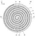
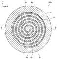
図1は、第1実施形態における加熱装置100の外観構成を概略的に示す斜視図であり、図2は、第1実施形態における加熱装置100の平面(上面)構成を概略的に示す説明図であり、図3から図5は、第1実施形態における加熱装置100の断面構成を概略的に示す説明図である。図3には、図2,4,5のIII−IIIの位置における加熱装置100のXZ断面構成が示されており、図4には、図3のIV−IVの位置における加熱装置100のXY断面構成が示されており、図5には、図3のV−Vの位置における加熱装置100のXY断面構成が示されている。各図には、方向を特定するための互いに直交するXYZ軸が示されている。本明細書では、便宜的に、Z軸正方向を上方向といい、Z軸負方向を下方向というものとするが、加熱装置100は実際にはそのような向きとは異なる向きで設置されてもよい。図6以降についても同様である。A. First Embodiment:
A-1. Configuration of heating device 100:
FIG. 1 is a perspective view schematically showing an external configuration of the
加熱装置100は、対象物(例えば、半導体ウェハW)を保持しつつ所定の処理温度(例えば、400〜650℃程度)に加熱する装置であり、サセプタとも呼ばれる。加熱装置100は、例えば、成膜装置(CVD成膜装置やスパッタリング成膜装置等)やエッチング装置(プラズマエッチング装置等)といった半導体製造装置の一部として使用される。 The
加熱装置100は、保持体10と柱状支持体20とを備える。 The
保持体10は、所定の方向(本実施形態では上下方向、すなわちZ軸方向)に略直交する保持面S1および裏面S2を有する略円板状の部材である。保持体10は、例えば、AlN(窒化アルミニウム)やAl2O3(アルミナ)を主成分とするセラミックスにより形成されている。なお、ここでいう主成分とは、含有割合(重量割合)の最も多い成分を意味する。保持体10の直径は、例えば100mm以上、500mm以下程度であり、保持体10の厚さ(上下方向における長さ)は、例えば3mm以上、10mm以下程度である。上記所定の方向(上下方向)は、特許請求の範囲における第1の方向に相当し、保持体10の保持面S1は、特許請求の範囲における第1の表面に相当し、保持体10の裏面S2は、特許請求の範囲における第2の表面に相当する。The holding
柱状支持体20は、上記所定の方向(上下方向)に延びる略円柱状部材である。柱状支持体20には、上面S3から下面S4まで上下方向に貫通する貫通孔22が形成されている。柱状支持体20は、保持体10と同様に、例えばAlNやAl2O3を主成分とするセラミックスにより形成されている。柱状支持体20の外径は、例えば30mm以上、90mm以下程度であり、柱状支持体20の高さ(上下方向における長さ)は、例えば100mm以上、300mm以下程度である。The
保持体10と柱状支持体20とは、保持体10の裏面S2と柱状支持体20の上面S3とが上下方向に対向するように配置されている。柱状支持体20は、保持体10の裏面S2の中心部付近に、公知の接合材料により形成された接合層30を介して接合されている。 The holding
図3から図5に示すように、保持体10の内部には、保持体10を加熱するヒータとしての3つの抵抗発熱体(第1の抵抗発熱体51,第2の抵抗発熱体52,第3の抵抗発熱体53)が配置されている。各抵抗発熱体51,52,53は、例えば、タングステンやモリブデン等の導電性材料により形成されている。 As shown in FIGS. 3 to 5, inside the holding
ここで、本実施形態の加熱装置100では、保持体10において、第1の領域R1と、第2の領域R2と、第3の領域R3とが設定されている。第1の領域R1は、Z軸方向視で柱状支持体20と重なる略円柱状の領域である。また、第2の領域R2は、Z軸方向視で第1の領域R1の外周側に隣接するように位置し、かつ、柱状支持体20と重ならない略円筒状の領域である。また、第3の領域R3は、Z軸方向視で第2の領域R2の外周側に隣接するように位置し、かつ、保持体10の外周線を含む略円筒状の領域である。すなわち、Z軸方向視で、第1の領域R1は保持体10の中心部に位置し、第3の領域R3は保持体10の周縁部に位置し、第2の領域R2は第1の領域R1と第3の領域R3との間に位置する。Z軸方向視における第1の領域R1と第2の領域R2との境界線B1の位置は、柱状支持体20の外周線の位置に相当する。また、Z軸方向視における第2の領域R2と第3の領域R3との境界線B2の位置は、適宜設定される。例えば、境界線B2の位置は、保持体10の外周線の位置から、保持体10の直径の1/5から1/18程度だけ内側に入った位置に設定される。なお、「Z軸方向視で柱状支持体20と重なる」とは、Z軸方向視で柱状支持体20の外周線に囲まれた領域と重なることを意味し、「Z軸方向視で柱状支持体20と重ならない」とは、Z軸方向視で柱状支持体20の外周線に囲まれた領域と重ならないことを意味する。 Here, in the
図4に示すように、第1の抵抗発熱体51は、保持体10における第1の領域R1と第2の領域R2とにわたって配置されている。すなわち、第1の抵抗発熱体51は、Z軸方向視で保持体10における周縁部を除く部分に配置されている。また、第3の抵抗発熱体53は、保持体10における第3の領域R3のみに配置されている。すなわち、第3の抵抗発熱体53は、Z軸方向視で保持体10における周縁部に配置されている。第3の抵抗発熱体53の上下方向における位置は、第1の抵抗発熱体51の上下方向における位置と略同一である。なお、本実施形態では、第1の抵抗発熱体51および第3の抵抗発熱体53は、Z軸方向視で略螺旋状のパターンを構成している。 As shown in FIG. 4, the first
一方、図5に示すように、第2の抵抗発熱体52は、保持体10における第1の領域R1のみに配置されている。すなわち、第2の抵抗発熱体52は、Z軸方向視で保持体10における中心部(柱状支持体20と重なる部分)に配置されている。第2の抵抗発熱体52の上下方向における位置は、第1の抵抗発熱体51より保持面S1に近い位置(すなわち、第1の抵抗発熱体51より上側の位置)である。なお、本実施形態では、第2の抵抗発熱体52は、Z軸方向視で略螺旋状のパターンを構成している。 On the other hand, as shown in FIG. 5, the second
加熱装置100は、3つの抵抗発熱体51,52,53のそれぞれに電圧を印加するための構成を備えている。具体的には、柱状支持体20の貫通孔22内には、3つの抵抗発熱体51,52,53のそれぞれに対応する一対の電極端子56が収容されている。第1の抵抗発熱体51に対応する一対の電極端子56の内の一方は、保持体10の裏面S2側に設けられた受電電極(電極パッド)54、および、保持体10の内部に設けられたビア導体55を介して、第1の抵抗発熱体51の一方の端部に電気的に接続されている。また、第1の抵抗発熱体51に対応する一対の電極端子56の内の他方は、他の受電電極54およびビア導体55を介して、第1の抵抗発熱体51の他方の端部に電気的に接続されている。第2の抵抗発熱体52に対応する一対の電極端子56および第3の抵抗発熱体53に対応する一対の電極端子56についても、同様に、それぞれ対応する受電電極54およびビア導体55を介して、第2の抵抗発熱体52または第3の抵抗発熱体53の各端部に電気的に接続されている。 The
このように、3つの抵抗発熱体51,52,53は、互いに異なる一対の電極端子56に接続されている。なお、ここで言う「互いに異なる一対の電極端子56」とは、電極端子56の組合せが完全同一ではないことを意味する。すなわち、3つの抵抗発熱体51,52,53が互いに異なる一対の電極端子56に接続されているとは、一の抵抗発熱体(例えば第1の抵抗発熱体51)に接続された一対の電極端子56の一方は、他の一の抵抗発熱体(例えば第2の抵抗発熱体52)に接続されていないが、該一の抵抗発熱体(例えば第1の抵抗発熱体51)に接続された一対の電極端子56の他方は、該他の一の抵抗発熱体(例えば第2の抵抗発熱体52)に接続されている形態を含んでいる。 In this way, the three
電源(図示せず)から第1の抵抗発熱体51に対応する一対の電極端子56、一対の受電電極54、および、一対のビア導体55を介して、第1の抵抗発熱体51に電圧が印加されると、第1の抵抗発熱体51が発熱する。第2の抵抗発熱体52および第3の抵抗発熱体53についても同様に、電圧が印加されると発熱する。各抵抗発熱体51,52,53が発熱することにより、保持体10が加熱され、保持体10の保持面S1上に保持された対象物(例えば、半導体ウェハW)が所定の温度(例えば、400〜650℃程度)に加熱される。上述したように、各抵抗発熱体51,52,53は互いに異なる一対の電極端子56に接続されているため、各抵抗発熱体51,52,53の発熱制御は個別に実行可能である。 A voltage is applied from a power source (not shown) to the first
なお、柱状支持体20の貫通孔22内には、図示しない熱電対が収容されており、熱電対の上端部は保持体10の中央部に埋め込まれている。熱電対により保持体10の温度が測定され、その測定結果に基づき保持体10の保持面S1の温度制御が実現される。 A thermocouple (not shown) is housed in the through
A−2.加熱装置100の製造方法:
加熱装置100の製造方法は、例えば以下の通りである。初めに、保持体10と柱状支持体20とを作製する。A-2. Manufacturing method of heating device 100:
The manufacturing method of the
保持体10の作製方法は、例えば以下の通りである。まず、窒化アルミニウム粉末100重量部に、酸化イットリウム(Y2O3)粉末1重量部と、アクリル系バインダ20重量部と、適量の分散剤および可塑剤とを加えた混合物に、トルエン等の有機溶剤を加え、ボールミルにて混合し、グリーンシート用スラリーを作製する。このグリーンシート用スラリーをキャスティング装置でシート状に成形した後に乾燥させ、グリーンシートを複数枚作製する。The method for producing the
また、窒化アルミニウム粉末、アクリル系バインダ、テルピネオール等の有機溶剤の混合物に、タングステンやモリブデン等の導電性粉末を添加して混練することにより、メタライズペーストを作製する。このメタライズペーストを例えばスクリーン印刷装置を用いて印刷することにより、特定の各グリーンシートに、後に各抵抗発熱体51,52,53や受電電極54等となる未焼結導体層を形成する。また、グリーンシートにあらかじめビア孔を設けた状態で印刷することにより、後にビア導体55となる未焼結導体部を形成する。 Further, a metallized paste is prepared by adding a conductive powder such as tungsten or molybdenum to a mixture of organic solvents such as aluminum nitride powder, acrylic binder and terpineol and kneading the mixture. By printing this metallized paste using, for example, a screen printing device, an unsintered conductor layer to be a
次に、これらのグリーンシートを複数枚(例えば20枚)熱圧着し、必要に応じて外周を切断して、グリーンシート積層体を作製する。このグリーンシート積層体をマシニングによって切削加工して円板状の成形体を作製し、この成形体を脱脂し、さらにこの脱脂体を焼成して焼成体を作製する。この焼成体の表面を研磨加工する。以上の工程により、保持体10が作製される。 Next, a plurality of these green sheets (for example, 20 sheets) are thermocompression-bonded, and the outer periphery is cut if necessary to prepare a green sheet laminate. This green sheet laminate is cut by machining to produce a disk-shaped molded body, the molded body is degreased, and the degreased body is further fired to produce a fired body. The surface of this fired body is polished. The holding
また、柱状支持体20の作製方法、例えば以下の通りである。まず、窒化アルミニウム粉末100重量部に、酸化イットリウム粉末1重量部と、PVAバインダ3重量部と、適量の分散剤および可塑剤とを加えた混合物に、メタノール等の有機溶剤を加え、ボールミルにて混合し、スラリーを得る。このスラリーをスプレードライヤーにて顆粒化し、原料粉末を作製する。次に、貫通孔22に対応する中子が配置されたゴム型に原料粉末を充填し、冷間静水圧プレスして成形体を得る。得られた成形体を脱脂し、さらにこの脱脂体を焼成する。以上の工程により、柱状支持体20が作製される。 Further, a method for manufacturing the
次に、保持体10と柱状支持体20とを接合する。保持体10の裏面S2および柱状支持体20の上面S3に対して必要によりラッピング加工を行った後、保持体10の裏面S2と柱状支持体20の上面S3との少なくとも一方に、例えば希土類や有機溶剤等を混合してペースト状にした公知の接合剤を均一に塗布した後、脱脂処理する。次いで、保持体10の裏面S2と柱状支持体20の上面S3とを重ね合わせ、ホットプレス焼成を行うことにより、保持体10と柱状支持体20とを接合する。 Next, the holding
保持体10と柱状支持体20との接合の後、各電極端子56を貫通孔22内に挿入し、各電極端子56の上端部を各受電電極54に例えば金ろう材によりろう付けする。また、熱電対を貫通孔22内に挿入し、熱電対の上端部を埋設固定する。以上の製造方法により、上述した構成の加熱装置100が製造される。 After joining the holding
A−3.第1実施形態の効果:
以上説明したように、本実施形態の加熱装置100は、Z軸方向に略直交する保持面S1および裏面S2を有する板状であり、内部に、互いに異なる一対の電極端子56に接続される複数の抵抗発熱体を有する保持体10と、Z軸方向に延びる柱状であり、保持体10の裏面S2に接合された柱状支持体20とを備え、保持体10の保持面S1上に保持された半導体ウェハW等の対象物を加熱する装置である。A-3. Effect of the first embodiment:
As described above, the
ここで、保持体10において、Z軸方向視で柱状支持体20と重なる領域である第1の領域R1は、柱状支持体20を介した熱逃げによって温度が低下しやすい領域である。一方、保持体10において、Z軸方向視で第1の領域R1の外周側に位置すると共に柱状支持体20と重ならない領域である第2の領域R2は、柱状支持体20を介した熱逃げの影響を受けにくい領域である。そのため、保持面S1の内の第1の領域R1に属する部分は、保持面S1の内の第2の領域R2に属する部分と比較して温度が低くなりやすく、その結果、保持面S1の面内均熱性が低くなるおそれがある。 Here, in the holding
本実施形態の加熱装置100では、上記複数の抵抗発熱体が、第1の領域R1と第2の領域R2とにわたって配置された第1の抵抗発熱体51に加えて、第1の領域R1のみに配置された第2の抵抗発熱体52を含む。第2の抵抗発熱体52は、第1の抵抗発熱体51に接続される一対の電極端子56とは異なる一対の電極端子56に接続されるため、第1の抵抗発熱体51とは独立して制御され得る。そのため、本実施形態の加熱装置100では、第1の抵抗発熱体51を発熱させることによって保持体10における第1の領域R1および第2の領域R2を加熱しつつ、それとは独立して、第2の抵抗発熱体52を発熱させることによって保持体10における第1の領域R1を加熱することができる。従って、本実施形態の加熱装置100では、第2の抵抗発熱体52を用いた保持体10の第1の領域R1の加熱によって、柱状支持体20を介した熱逃げの影響による保持面S1の面内均熱性の低下を抑制することができる。また、本実施形態の加熱装置100では、第2の抵抗発熱体52が、Z軸方向において第1の抵抗発熱体51より保持面S1に近い位置に配置されている。そのため、第2の抵抗発熱体52を発熱させることによって、保持面S1における第1の領域R1に属する部分の温度を迅速に高くすることができ、保持面S1の面内均熱性を迅速にかつ高度に向上させることができる。 In the
また、本実施形態の加熱装置100では、上記複数の抵抗発熱体が、さらに、Z軸方向において第1の抵抗発熱体51と略同一の位置に配置され、かつ、Z軸方向視で第2の領域R2の外周側に位置する第3の領域R3のみに配置された第3の抵抗発熱体53を含む。保持体10における第3の領域R3は、Z軸方向視で周縁部の領域である。第3の抵抗発熱体53は、第1の抵抗発熱体51および第2の抵抗発熱体52に接続される一対の電極端子56とは異なる一対の電極端子56に接続されるため、第1の抵抗発熱体51および第2の抵抗発熱体52とは独立して制御され得る。そのため、本実施形態の加熱装置100では、第1の抵抗発熱体51や第2の抵抗発熱体52を用いた第1の領域R1や第2の領域R2の加熱とは独立して、第3の抵抗発熱体53を発熱させることによって保持体10における第3の領域R3を加熱することができる。従って、本実施形態の加熱装置100では、第3の抵抗発熱体53を用いた保持体10の第3の領域R3の加熱によって、保持面S1の周縁部の温度を制御することができ、保持面S1の面内均熱性をさらに向上させることができる。また、本実施形態の加熱装置100では、第3の抵抗発熱体53が、Z軸方向において第1の抵抗発熱体51と略同一の位置、すなわち、第2の抵抗発熱体52と比較して保持面S1から離れた位置に配置されている。そのため、第3の抵抗発熱体53から発した熱が保持面S1に伝わるまでの経路を長くすることができ、保持面S1における第2の領域R2と第3の領域R3との境界付近における温度差を低下させて、保持面S1の面内均熱性をさらに向上させることができる。 Further, in the
B.第2実施形態:
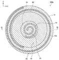
図6から図8は、第2実施形態の加熱装置100aの断面構成を概略的に示す説明図である。図6には、図7および図8のVI−VIの位置における加熱装置100aのXZ断面構成が示されており、図7には、図6のVII−VIIの位置における加熱装置100aのXY断面構成が示されており、図8には、図6のVIII−VIIIの位置における加熱装置100aのXY断面構成が示されている。以下では、第2実施形態の加熱装置100aの構成の内、上述した第1実施形態の加熱装置100の構成と同一の構成については、同一の符号を付すことによってその説明を適宜省略する。B. Second embodiment:
6 to 8 are explanatory views schematically showing a cross-sectional configuration of the
第2実施形態の加熱装置100aは、第3の抵抗発熱体53aの構成が、上述した第1実施形態の加熱装置100と異なっている。具体的には、第2実施形態の加熱装置100aでは、第3の抵抗発熱体53aの上下方向における位置は、第1の抵抗発熱体51ではなく第2の抵抗発熱体52の上下方向における位置と略同一である。第2実施形態の加熱装置100aのその他の構成は、上述した第1実施形態の加熱装置100の構成と同様である。 The
第2実施形態の加熱装置100aでは、上述した第1実施形態の加熱装置100と同様に、保持体10の内部に複数の抵抗発熱体が設けられており、該複数の抵抗発熱体が、第1の領域R1と第2の領域R2とにわたって配置された第1の抵抗発熱体51に加えて、第1の領域R1のみに配置された第2の抵抗発熱体52を含む。そのため、第2の抵抗発熱体52を用いた保持体10の第1の領域R1の加熱によって、柱状支持体20を介した熱逃げの影響による保持面S1の面内均熱性の低下を抑制することができる。また、第2の抵抗発熱体52が、Z軸方向において第1の抵抗発熱体51より保持面S1に近い位置に配置されているため、第2の抵抗発熱体52を発熱させることによって、保持面S1における第1の領域R1に属する部分の温度を迅速に高くすることができ、保持面S1の面内均熱性を迅速にかつ高度に向上させることができる。 In the
また、第2実施形態の加熱装置100aでは、上記複数の抵抗発熱体が、さらに、Z軸方向において第2の抵抗発熱体52と略同一の位置に配置され、かつ、Z軸方向視で第2の領域R2の外周側に位置する第3の領域R3のみに配置された第3の抵抗発熱体53aを含む。そのため、第2実施形態の加熱装置100aでは、第3の抵抗発熱体53aを用いた保持体10の第3の領域R3の加熱によって、保持面S1の周縁部の温度を制御することができ、保持面S1の面内均熱性をさらに向上させることができる。また、第2実施形態の加熱装置100aでは、第3の抵抗発熱体53aが、Z軸方向において第2の抵抗発熱体52と略同一の位置、すなわち、第1の抵抗発熱体51と比較して保持面S1に近い位置に配置されている。そのため、第3の抵抗発熱体53を発熱させることによって、保持面S1における第3の領域R3に属する部分の温度を迅速に高くすることができ、保持面S1の面内均熱性を迅速にかつ高度に向上させることができる。 Further, in the
C.変形例:
本明細書で開示される技術は、上述の実施形態に限られるものではなく、その要旨を逸脱しない範囲において種々の形態に変形することができ、例えば次のような変形も可能である。C. Modification example:
The technique disclosed in the present specification is not limited to the above-described embodiment, and can be transformed into various forms without departing from the gist thereof. For example, the following modifications are also possible.
上記実施形態における加熱装置100の構成は、あくまで例示であり、種々変形可能である。例えば、上記実施形態では、保持体10および柱状支持体20のZ軸方向視の外形が略円形であるとしているが、他の形状であってもよい。また、上記実施形態では、各抵抗発熱体51,52,53のZ軸方向視の形状が略螺旋状であるとしているが、他の形状であってもよい。 The configuration of the
また、上記実施形態では、保持体10に設定される第1の領域R1は、Z軸方向視で柱状支持体20と重なる領域であるとしているが、第1の領域R1は、必ずしも全域がZ軸方向視で柱状支持体20と重なる領域である必要はなく、Z軸方向視で柱状支持体20と重なる領域を含む領域であればよい。また、上記実施形態では、保持体10に設定される第2の領域R2は、Z軸方向視で柱状支持体20と重ならない領域であるとしているが、第2の領域R2は、必ずしも全域がZ軸方向視で柱状支持体20と重ならない領域である必要はなく、Z軸方向視で柱状支持体20と重ならない領域を含む領域であればよい。 Further, in the above embodiment, the first region R1 set in the holding
また、上記実施形態では、第2の領域R2は、Z軸方向視で第1の領域R1の外周側に隣接するとしているが、第2の領域R2は、Z軸方向視で第1の領域R1の外周側に位置すればよく、必ずしも第1の領域R1に隣接する必要はない。また、上記実施形態では、第3の領域R3は、Z軸方向視で第2の領域R2の外周側に隣接するとしているが、第3の領域R3は、Z軸方向視で第2の領域R2の外周側に位置すればよく、必ずしも第2の領域R2に隣接する必要はない。 Further, in the above embodiment, the second region R2 is adjacent to the outer peripheral side of the first region R1 in the Z-axis direction, but the second region R2 is the first region in the Z-axis direction. It suffices to be located on the outer peripheral side of R1 and does not necessarily have to be adjacent to the first region R1. Further, in the above embodiment, the third region R3 is adjacent to the outer peripheral side of the second region R2 in the Z-axis direction, but the third region R3 is the second region in the Z-axis direction. It may be located on the outer peripheral side of R2 and does not necessarily have to be adjacent to the second region R2.
また、上記実施形態では、第1の領域R1はZ軸方向視で略円柱形状であり、第2の領域R2および第3の領域R3はZ軸方向視で略円筒形状であるが、各領域R1、R2、R3の形状は任意に変形可能である。また、上記実施形態では、保持体10に3つの領域(第1の領域R1、第2の領域R2、第3の領域R3)が設定されているが、必ずしも保持体10に第3の領域R3が設定される必要はない。すなわち、必ずしも保持体10の内部に第3の抵抗発熱体53が設けられる必要はない。また、保持体10の内部に、第1〜3の抵抗発熱体51,52,53以外の抵抗発熱体が設けられているとしてもよい。 Further, in the above embodiment, the first region R1 has a substantially cylindrical shape in the Z-axis direction, and the second region R2 and the third region R3 have a substantially cylindrical shape in the Z-axis direction. The shapes of R1, R2, and R3 can be arbitrarily deformed. Further, in the above embodiment, three regions (first region R1, second region R2, third region R3) are set in the holding
また、上記実施形態における加熱装置100を構成する各部材の形成材料は、あくまで例示であり、各部材が他の材料により形成されてもよい。例えば、上記実施形態における加熱装置100では、保持体10および柱状支持体20は、窒化アルミニウムまたはアルミナを主成分とするセラミックス製であるとしているが、保持体10と柱状支持体20との少なくとも一方が、他のセラミックス製であるとしてもよいし、セラミックス以外の材料製(例えば、アルミニウムやアルミニウム合金等の金属製)であるとしてもよい。 Further, the forming material of each member constituting the
また、上記実施形態における加熱装置100の製造方法はあくまで一例であり、種々変形可能である。 Further, the manufacturing method of the
10:保持体 20:柱状支持体 22:貫通孔 30:接合層 51:第1の抵抗発熱体 52:第2の抵抗発熱体 53:第3の抵抗発熱体 54:受電電極 55:ビア導体 56:電極端子 100:加熱装置10: Holder 20: Columnar support 22: Through hole 30: Bonding layer 51: First resistance heating element 52: Second resistance heating element 53: Third resistance heating element 54: Power receiving electrode 55: Via conductor 56 : Electrode terminal 100: Heating device
Claims (2)
Translated fromJapanese前記第1の方向に延びる柱状であり、前記保持体の前記第2の表面に接合された柱状支持体と、
を備え、前記保持体の前記第1の表面上に保持された対象物を加熱する加熱装置において、
前記複数の抵抗発熱体は、
前記第1の方向視で前記柱状支持体と重なる領域を含む第1の領域と、前記第1の方向視で前記第1の領域の外周側に位置すると共に前記柱状支持体と重ならない領域を含む第2の領域と、にわたって配置された第1の抵抗発熱体と、
前記第1の方向において前記第1の抵抗発熱体より前記第1の表面に近い位置に配置され、かつ、前記第1の領域のみに配置された第2の抵抗発熱体と、
前記第1の方向において前記第1の抵抗発熱体と略同一の位置に配置され、かつ、前記第1の方向視で前記第2の領域の外周側に位置する第3の領域のみに配置された第3の抵抗発熱体と、
を含むことを特徴とする、加熱装置。A holder having a plate-like shape having first and second surfaces substantially orthogonal to the first direction and having a plurality of resistance heating elements connected to a pair of different electrode terminals inside.
A columnar support extending in the first direction and joined to the second surface of the holding body, and a columnar support.
In a heating device for heating an object held on the first surface of the holder.
The plurality of resistance heating elements
A first region including a region overlapping the columnar support in the first directional view and a region located on the outer peripheral side of the first region in the first directional view and not overlapping the columnar support. A second region containing, a first resistance heating element disposed over, and
A second resistance heating element arranged at a position closer to the first surface than the first resistance heating element in the first direction and arranged only in the first region.
It is arranged at substantially the same position as the first resistance heating element in the first direction, and is arranged only in a third region located on the outer peripheral side of the second region in the first direction view. And a third resistance heating element
A heating device, characterized in that it contains.
前記第1の方向に延びる柱状であり、前記保持体の前記第2の表面に接合された柱状支持体と、 A columnar support extending in the first direction and joined to the second surface of the holding body, and a columnar support.
を備え、前記保持体の前記第1の表面上に保持された対象物を加熱する加熱装置において、In a heating device for heating an object held on the first surface of the holder.
前記複数の抵抗発熱体は、 The plurality of resistance heating elements
前記第1の方向視で前記柱状支持体と重なる領域を含む第1の領域と、前記第1の方向視で前記第1の領域の外周側に位置すると共に前記柱状支持体と重ならない領域を含む第2の領域と、にわたって配置された第1の抵抗発熱体と、 A first region including a region overlapping the columnar support in the first directional view and a region located on the outer peripheral side of the first region in the first directional view and not overlapping the columnar support. A second region containing, a first resistance heating element disposed over, and
前記第1の方向において前記第1の抵抗発熱体より前記第1の表面に近い位置に配置され、かつ、前記第1の領域のみに配置された第2の抵抗発熱体と、 A second resistance heating element arranged at a position closer to the first surface than the first resistance heating element in the first direction and arranged only in the first region.
前記第1の方向において前記第2の抵抗発熱体と略同一の位置に配置され、かつ、前記第1の方向視で前記第2の領域の外周側に位置する第3の領域のみに配置された第3の抵抗発熱体と、 It is arranged at substantially the same position as the second resistance heating element in the first direction, and is arranged only in a third region located on the outer peripheral side of the second region in the first direction. And a third resistance heating element
を含むことを特徴とする、加熱装置。A heating device, characterized in that it contains.
Priority Applications (5)
| Application Number | Priority Date | Filing Date | Title |
|---|---|---|---|
| JP2016190605AJP6758143B2 (en) | 2016-09-29 | 2016-09-29 | Heating device |
| TW106133299ATWI700959B (en) | 2016-09-29 | 2017-09-28 | Heating device |
| CN201710901246.XACN107889289B (en) | 2016-09-29 | 2017-09-28 | Heating device |
| US15/718,440US10615060B2 (en) | 2016-09-29 | 2017-09-28 | Heating device |
| KR1020170126330AKR20180035712A (en) | 2016-09-29 | 2017-09-28 | Heating device |
Applications Claiming Priority (1)
| Application Number | Priority Date | Filing Date | Title |
|---|---|---|---|
| JP2016190605AJP6758143B2 (en) | 2016-09-29 | 2016-09-29 | Heating device |
Publications (2)
| Publication Number | Publication Date |
|---|---|
| JP2018056332A JP2018056332A (en) | 2018-04-05 |
| JP6758143B2true JP6758143B2 (en) | 2020-09-23 |
Family
ID=61686652
Family Applications (1)
| Application Number | Title | Priority Date | Filing Date |
|---|---|---|---|
| JP2016190605AActiveJP6758143B2 (en) | 2016-09-29 | 2016-09-29 | Heating device |
Country Status (5)
| Country | Link |
|---|---|
| US (1) | US10615060B2 (en) |
| JP (1) | JP6758143B2 (en) |
| KR (1) | KR20180035712A (en) |
| CN (1) | CN107889289B (en) |
| TW (1) | TWI700959B (en) |
Families Citing this family (9)
| Publication number | Priority date | Publication date | Assignee | Title |
|---|---|---|---|---|
| JP7237776B2 (en)* | 2019-08-27 | 2023-03-13 | 京セラ株式会社 | Wafer member and wafer equipment |
| JP7427517B2 (en)* | 2020-04-27 | 2024-02-05 | 京セラ株式会社 | heater |
| JP7383575B2 (en)* | 2020-06-29 | 2023-11-20 | 日本特殊陶業株式会社 | holding device |
| KR102815377B1 (en)* | 2020-08-05 | 2025-06-02 | 주식회사 원익아이피에스 | Substrate supporting unit and substrate processing apparatus having the same |
| JP7321990B2 (en)* | 2020-11-30 | 2023-08-07 | 日本碍子株式会社 | ceramic heater |
| JP7407752B2 (en)* | 2021-02-05 | 2024-01-04 | 日本碍子株式会社 | wafer support stand |
| KR102658726B1 (en) | 2021-12-03 | 2024-04-18 | 주식회사 케이에스엠컴포넌트 | Heating device for semiconductor manufacturing equipment |
| WO2024171391A1 (en)* | 2023-02-16 | 2024-08-22 | 日本碍子株式会社 | Ceramic heater |
| JP7642159B1 (en)* | 2023-08-18 | 2025-03-07 | 日本碍子株式会社 | Multi-Zone Ceramic Heater |
Family Cites Families (72)
| Publication number | Priority date | Publication date | Assignee | Title |
|---|---|---|---|---|
| US6616767B2 (en)* | 1997-02-12 | 2003-09-09 | Applied Materials, Inc. | High temperature ceramic heater assembly with RF capability |
| JPH10242252A (en) | 1997-02-28 | 1998-09-11 | Kyocera Corp | Wafer heating device |
| JP3293594B2 (en)* | 1999-06-29 | 2002-06-17 | 住友電気工業株式会社 | Apparatus and method for heating protective member of optical fiber fusion spliced part |
| JP2001118664A (en)* | 1999-08-09 | 2001-04-27 | Ibiden Co Ltd | Ceramic heater |
| WO2001039551A1 (en)* | 1999-11-19 | 2001-05-31 | Ibiden Co., Ltd. | Ceramic heater |
| JP3228923B2 (en)* | 2000-01-18 | 2001-11-12 | イビデン株式会社 | Ceramic heater for semiconductor manufacturing and inspection equipment |
| JP3228924B2 (en)* | 2000-01-21 | 2001-11-12 | イビデン株式会社 | Ceramic heater for semiconductor manufacturing and inspection equipment |
| JP4028149B2 (en)* | 2000-02-03 | 2007-12-26 | 日本碍子株式会社 | Heating device |
| WO2001058828A1 (en)* | 2000-02-07 | 2001-08-16 | Ibiden Co., Ltd. | Ceramic substrate for semiconductor production/inspection device |
| WO2001059833A1 (en)* | 2000-02-08 | 2001-08-16 | Ibiden Co., Ltd. | Ceramic board for semiconductor production and inspection devices |
| WO2001062686A1 (en)* | 2000-02-24 | 2001-08-30 | Ibiden Co., Ltd. | Aluminum nitride sintered compact, ceramic substrate, ceramic heater and electrostatic chuck |
| JP2001244320A (en)* | 2000-02-25 | 2001-09-07 | Ibiden Co Ltd | Ceramic substrate and manufacturing method therefor |
| US20030098299A1 (en)* | 2000-03-06 | 2003-05-29 | Ibiden Co., Ltd. | Ceramic heater |
| WO2001078454A1 (en)* | 2000-04-07 | 2001-10-18 | Ibiden Co., Ltd. | Ceramic heater |
| US6677557B2 (en)* | 2000-05-02 | 2004-01-13 | Ibiden Co., Ltd. | Ceramic heater |
| JP4398064B2 (en)* | 2000-05-12 | 2010-01-13 | 日本発條株式会社 | Heating device |
| US6815646B2 (en)* | 2000-07-25 | 2004-11-09 | Ibiden Co., Ltd. | Ceramic substrate for semiconductor manufacture/inspection apparatus, ceramic heater, electrostatic clampless holder, and substrate for wafer prober |
| JP3615694B2 (en)* | 2000-08-08 | 2005-02-02 | 京セラ株式会社 | Wafer heating member and wafer soaking method using the same |
| JP4328003B2 (en)* | 2000-10-19 | 2009-09-09 | 日本碍子株式会社 | Ceramic heater |
| JP4156788B2 (en)* | 2000-10-23 | 2008-09-24 | 日本碍子株式会社 | Susceptor for semiconductor manufacturing equipment |
| JP4328009B2 (en)* | 2000-11-30 | 2009-09-09 | 日本碍子株式会社 | Heating device |
| EP1341216A1 (en)* | 2000-12-05 | 2003-09-03 | Ibiden Co., Ltd. | Ceramic substrate for semiconductor manufacturing and inspecting devices, and method of manufacturing the ceramic substrate |
| US6997993B2 (en)* | 2001-02-09 | 2006-02-14 | Ngk Insulators, Ltd. | Susceptor supporting construction |
| WO2002083596A1 (en)* | 2001-04-13 | 2002-10-24 | Sumitomo Electric Industries, Ltd. | Joined ceramic article, substrate holding structure and apparatus for treating substrate |
| US20020185487A1 (en)* | 2001-05-02 | 2002-12-12 | Ramesh Divakar | Ceramic heater with heater element and method for use thereof |
| JP3897563B2 (en)* | 2001-10-24 | 2007-03-28 | 日本碍子株式会社 | Heating device |
| JP3982674B2 (en)* | 2001-11-19 | 2007-09-26 | 日本碍子株式会社 | Ceramic heater, method for manufacturing the same, and heating device for semiconductor manufacturing apparatus |
| JPWO2003047312A1 (en)* | 2001-11-30 | 2005-04-14 | イビデン株式会社 | Ceramic heater |
| JP3840990B2 (en)* | 2002-03-05 | 2006-11-01 | 住友電気工業株式会社 | Semiconductor / LCD manufacturing equipment |
| JP3888531B2 (en)* | 2002-03-27 | 2007-03-07 | 日本碍子株式会社 | Ceramic heater, method for manufacturing ceramic heater, and buried article of metal member |
| JP4026761B2 (en)* | 2002-03-28 | 2007-12-26 | 日本碍子株式会社 | Ceramic heater |
| KR100511854B1 (en)* | 2002-06-18 | 2005-09-02 | 아네르바 가부시키가이샤 | Electrostatic chuck device |
| JP4119211B2 (en)* | 2002-09-13 | 2008-07-16 | 日本碍子株式会社 | Heating device |
| JP3832409B2 (en)* | 2002-09-18 | 2006-10-11 | 住友電気工業株式会社 | Wafer holder and semiconductor manufacturing apparatus |
| WO2004030411A1 (en)* | 2002-09-27 | 2004-04-08 | Sumitomo Electric Industries, Ltd. | Wafer holder and semiconductor production system |
| JP4671262B2 (en)* | 2003-01-21 | 2011-04-13 | 日本碍子株式会社 | Semiconductor heating device |
| US20040222210A1 (en)* | 2003-05-08 | 2004-11-11 | Hongy Lin | Multi-zone ceramic heating system and method of manufacture thereof |
| JP3918806B2 (en)* | 2003-11-20 | 2007-05-23 | 住友電気工業株式会社 | Heater member for placing object to be heated and heat treatment apparatus |
| US20050194374A1 (en)* | 2004-03-02 | 2005-09-08 | Applied Materials, Inc. | Heated ceramic substrate support with protective coating |
| TW200612512A (en)* | 2004-06-28 | 2006-04-16 | Ngk Insulators Ltd | Substrate heating sapparatus |
| WO2006004045A1 (en)* | 2004-07-05 | 2006-01-12 | Tokyo Electron Limited | Treating device and heater unit |
| TWI281833B (en)* | 2004-10-28 | 2007-05-21 | Kyocera Corp | Heater, wafer heating apparatus and method for manufacturing heater |
| JP4542485B2 (en)* | 2004-12-14 | 2010-09-15 | 日本碍子株式会社 | Alumina member and manufacturing method thereof |
| US7126092B2 (en)* | 2005-01-13 | 2006-10-24 | Watlow Electric Manufacturing Company | Heater for wafer processing and methods of operating and manufacturing the same |
| US8525418B2 (en)* | 2005-03-31 | 2013-09-03 | Ngk Spark Plug Co., Ltd. | Electrostatic chuck |
| JP2006302888A (en)* | 2005-04-19 | 2006-11-02 | Ngk Insulators Ltd | Power supply member and heating device |
| JP2006302887A (en)* | 2005-04-20 | 2006-11-02 | Ngk Insulators Ltd | Power supply member and heating device |
| JP4672597B2 (en)* | 2005-06-02 | 2011-04-20 | 日本碍子株式会社 | Substrate processing equipment |
| JP2007066542A (en)* | 2005-08-29 | 2007-03-15 | Kyocera Corp | Heater, wafer heating apparatus, and method for manufacturing the heater |
| JP4889385B2 (en)* | 2006-07-07 | 2012-03-07 | 日本発條株式会社 | Heater unit and shaft |
| KR20080037879A (en)* | 2006-10-27 | 2008-05-02 | 주식회사 코미코 | Heater and manufacturing method thereof |
| JP2008115440A (en)* | 2006-11-06 | 2008-05-22 | Shinko Electric Ind Co Ltd | Substrate heating apparatus |
| JP5029257B2 (en)* | 2007-01-17 | 2012-09-19 | 東京エレクトロン株式会社 | Mounting table structure and processing device |
| EP2186380B1 (en)* | 2007-07-20 | 2016-06-22 | LG Electronics Inc. | Electric heater |
| JP2009054871A (en)* | 2007-08-28 | 2009-03-12 | Tokyo Electron Ltd | Placing stand structure and treatment apparatus |
| JP4913695B2 (en)* | 2007-09-20 | 2012-04-11 | 東京エレクトロン株式会社 | Substrate processing apparatus and substrate mounting table used therefor |
| US8193473B2 (en)* | 2008-02-08 | 2012-06-05 | Ngk Insulators, Ltd. | Uniform temperature heater |
| KR101525634B1 (en)* | 2009-03-30 | 2015-06-03 | 엔지케이 인슐레이터 엘티디 | Ceramic heater and method for producing same |
| JP2015514661A (en)* | 2012-02-29 | 2015-05-21 | ハリス,ジョナサン・エイチ | Transient liquid phase, normal pressure bonding of aluminum nitride parts |
| JP5807032B2 (en)* | 2012-03-21 | 2015-11-10 | 日本碍子株式会社 | Heating apparatus and semiconductor manufacturing apparatus |
| JP6049509B2 (en)* | 2012-03-28 | 2016-12-21 | 日本碍子株式会社 | Manufacturing method of ceramic heater, heater electrode and ceramic heater |
| WO2014073554A1 (en)* | 2012-11-06 | 2014-05-15 | 日本碍子株式会社 | Susceptor |
| JP6084906B2 (en)* | 2013-07-11 | 2017-02-22 | 日本碍子株式会社 | Ceramic heater |
| CN104576442A (en)* | 2013-10-15 | 2015-04-29 | 住友电气工业株式会社 | Ceramic heating device used for semiconductor manufacturing device |
| CN104582019B (en)* | 2013-10-15 | 2019-01-04 | 住友电气工业株式会社 | Ceramic heater for semiconductor manufacturing apparatus |
| JP2015082384A (en)* | 2013-10-22 | 2015-04-27 | 東京エレクトロン株式会社 | Plasma processing apparatus, power feeding unit, and mounting stand system |
| JP6442296B2 (en)* | 2014-06-24 | 2018-12-19 | 東京エレクトロン株式会社 | Mounting table and plasma processing apparatus |
| CN107078093B (en)* | 2015-01-20 | 2020-01-07 | 日本碍子株式会社 | Shaft end portion mounting structure |
| JP6690918B2 (en)* | 2015-10-16 | 2020-04-28 | 日本特殊陶業株式会社 | Heating member, electrostatic chuck, and ceramic heater |
| JP6560150B2 (en)* | 2016-03-28 | 2019-08-14 | 日本碍子株式会社 | Wafer mounting device |
| US20180190501A1 (en)* | 2017-01-05 | 2018-07-05 | Tokyo Electron Limited | Plasma processing apparatus |
| JP6615134B2 (en)* | 2017-01-30 | 2019-12-04 | 日本碍子株式会社 | Wafer support |
- 2016
- 2016-09-29JPJP2016190605Apatent/JP6758143B2/enactiveActive
- 2017
- 2017-09-28USUS15/718,440patent/US10615060B2/ennot_activeExpired - Fee Related
- 2017-09-28CNCN201710901246.XApatent/CN107889289B/enactiveActive
- 2017-09-28KRKR1020170126330Apatent/KR20180035712A/ennot_activeCeased
- 2017-09-28TWTW106133299Apatent/TWI700959B/ennot_activeIP Right Cessation
Also Published As
| Publication number | Publication date |
|---|---|
| JP2018056332A (en) | 2018-04-05 |
| US10615060B2 (en) | 2020-04-07 |
| TW201826875A (en) | 2018-07-16 |
| KR20180035712A (en) | 2018-04-06 |
| TWI700959B (en) | 2020-08-01 |
| CN107889289B (en) | 2021-04-13 |
| CN107889289A (en) | 2018-04-06 |
| US20180090349A1 (en) | 2018-03-29 |
Similar Documents
| Publication | Publication Date | Title |
|---|---|---|
| JP6758143B2 (en) | Heating device | |
| JP6767833B2 (en) | Heating device | |
| JP7386624B2 (en) | Holding device and method for manufacturing the holding device | |
| CN107872903B (en) | Heating device | |
| JP7265930B2 (en) | Heating device and method for manufacturing the heating device | |
| JP7265941B2 (en) | zygote | |
| JP7227806B2 (en) | holding device | |
| JP6917180B2 (en) | Heating device | |
| JP7083262B2 (en) | Heating device | |
| JP7198635B2 (en) | holding device | |
| JP7125262B2 (en) | Gas distributor for shower head | |
| JP7640278B2 (en) | Retaining device | |
| JP7057103B2 (en) | Heating device | |
| JP6903512B2 (en) | Joined body | |
| JP7098376B2 (en) | Heating device | |
| JP2020174137A (en) | Holding device | |
| JP6695204B2 (en) | Holding device | |
| JP2020033236A (en) | Conjugate |
Legal Events
| Date | Code | Title | Description |
|---|---|---|---|
| A621 | Written request for application examination | Free format text:JAPANESE INTERMEDIATE CODE: A621 Effective date:20190813 | |
| A977 | Report on retrieval | Free format text:JAPANESE INTERMEDIATE CODE: A971007 Effective date:20200521 | |
| A131 | Notification of reasons for refusal | Free format text:JAPANESE INTERMEDIATE CODE: A131 Effective date:20200602 | |
| A521 | Request for written amendment filed | Free format text:JAPANESE INTERMEDIATE CODE: A523 Effective date:20200720 | |
| TRDD | Decision of grant or rejection written | ||
| A01 | Written decision to grant a patent or to grant a registration (utility model) | Free format text:JAPANESE INTERMEDIATE CODE: A01 Effective date:20200825 | |
| A61 | First payment of annual fees (during grant procedure) | Free format text:JAPANESE INTERMEDIATE CODE: A61 Effective date:20200901 | |
| R150 | Certificate of patent or registration of utility model | Ref document number:6758143 Country of ref document:JP Free format text:JAPANESE INTERMEDIATE CODE: R150 | |
| S531 | Written request for registration of change of domicile | Free format text:JAPANESE INTERMEDIATE CODE: R313531 | |
| R350 | Written notification of registration of transfer | Free format text:JAPANESE INTERMEDIATE CODE: R350 | |
| R250 | Receipt of annual fees | Free format text:JAPANESE INTERMEDIATE CODE: R250 | |
| R250 | Receipt of annual fees | Free format text:JAPANESE INTERMEDIATE CODE: R250 | |
| R250 | Receipt of annual fees | Free format text:JAPANESE INTERMEDIATE CODE: R250 |