JP6751062B2 - Automatic inspection system and automatic inspection method - Google Patents
Automatic inspection system and automatic inspection methodDownload PDFInfo
- Publication number
- JP6751062B2 JP6751062B2JP2017175507AJP2017175507AJP6751062B2JP 6751062 B2JP6751062 B2JP 6751062B2JP 2017175507 AJP2017175507 AJP 2017175507AJP 2017175507 AJP2017175507 AJP 2017175507AJP 6751062 B2JP6751062 B2JP 6751062B2
- Authority
- JP
- Japan
- Prior art keywords
- parameter
- measurement
- data
- information
- unit
- Prior art date
- Legal status (The legal status is an assumption and is not a legal conclusion. Google has not performed a legal analysis and makes no representation as to the accuracy of the status listed.)
- Active
Links
Images


Classifications
- G—PHYSICS
- G06—COMPUTING OR CALCULATING; COUNTING
- G06T—IMAGE DATA PROCESSING OR GENERATION, IN GENERAL
- G06T7/00—Image analysis
- G06T7/0002—Inspection of images, e.g. flaw detection
- H—ELECTRICITY
- H04—ELECTRIC COMMUNICATION TECHNIQUE
- H04Q—SELECTING
- H04Q9/00—Arrangements in telecontrol or telemetry systems for selectively calling a substation from a main station, in which substation desired apparatus is selected for applying a control signal thereto or for obtaining measured values therefrom
- G—PHYSICS
- G08—SIGNALLING
- G08C—TRANSMISSION SYSTEMS FOR MEASURED VALUES, CONTROL OR SIMILAR SIGNALS
- G08C19/00—Electric signal transmission systems
- G08C19/36—Electric signal transmission systems using optical means to covert the input signal
- H—ELECTRICITY
- H04—ELECTRIC COMMUNICATION TECHNIQUE
- H04Q—SELECTING
- H04Q9/00—Arrangements in telecontrol or telemetry systems for selectively calling a substation from a main station, in which substation desired apparatus is selected for applying a control signal thereto or for obtaining measured values therefrom
- H04Q9/02—Automatically-operated arrangements
- H—ELECTRICITY
- H04—ELECTRIC COMMUNICATION TECHNIQUE
- H04Q—SELECTING
- H04Q2209/00—Arrangements in telecontrol or telemetry systems
- H04Q2209/80—Arrangements in the sub-station, i.e. sensing device
- H04Q2209/88—Providing power supply at the sub-station
- H—ELECTRICITY
- H04—ELECTRIC COMMUNICATION TECHNIQUE
- H04Q—SELECTING
- H04Q2209/00—Arrangements in telecontrol or telemetry systems
- H04Q2209/80—Arrangements in the sub-station, i.e. sensing device
- H04Q2209/88—Providing power supply at the sub-station
- H04Q2209/883—Providing power supply at the sub-station where the sensing device enters an active or inactive mode
Landscapes
- Engineering & Computer Science (AREA)
- Physics & Mathematics (AREA)
- General Physics & Mathematics (AREA)
- Computer Networks & Wireless Communication (AREA)
- Quality & Reliability (AREA)
- Computer Vision & Pattern Recognition (AREA)
- Theoretical Computer Science (AREA)
- Arrangements For Transmission Of Measured Signals (AREA)
- Selective Calling Equipment (AREA)
Description
Translated fromJapanese本発明は、自動点検システムおよび自動点検方法に関する。 The present invention relates to an automatic inspection system and an automatic inspection method.
工場や変電所などのプラントに設置された流量計または電力計などのメータ(例えば、針式メータ)は、一日に数回ないし十数回程度の頻度でユーザが目視することにより、点検される。自動点検システムは、点検対象のメータを現場のカメラで撮影してセンタへ送信する。これにより、管理室内のユーザは、メータ値を遠隔から確認できる。 Meters (for example, needle meters) such as flow meters or electricity meters installed in plants such as factories and substations are inspected by the user's visual inspection several times to a dozen times a day. It The automatic inspection system photographs the meter to be inspected with a camera at the site and sends it to the center. This allows the user in the control room to remotely confirm the meter value.
このような自動点検システムで使用される計測装置は、外部からの給電が困難な場所に設置されることが多い。一方、計測装置は、長期間にわたって所定の頻度で計測データを送信し続ける必要がある。そこで、自動点検システムでは、計測装置の消費電力をできるだけ抑制し、電池等の自立電源により長時間動作することが求められる。 The measuring device used in such an automatic inspection system is often installed in a place where it is difficult to supply power from the outside. On the other hand, the measuring device needs to continue transmitting the measurement data at a predetermined frequency over a long period of time. Therefore, the automatic inspection system is required to suppress the power consumption of the measuring device as much as possible and operate for a long time by an independent power source such as a battery.
ところで、点検の対象(例えば、針式メータ)の状態をカメラのような光学式センサで検知する場合、読み取った画像を正確に解析するために、ピントや露光などの光学的条件を整える必要がある。しかし、計測装置は、屋外等に設置されることも多く、太陽光等の外乱の影響を強く受ける。また、屋内に設置された計測装置においても、照明装置の作動状態により影響を受ける。 By the way, when detecting the state of an object to be inspected (for example, a needle meter) with an optical sensor such as a camera, it is necessary to adjust optical conditions such as focus and exposure in order to accurately analyze the read image. is there. However, the measuring device is often installed outdoors or the like, and is strongly affected by disturbance such as sunlight. In addition, the measuring device installed indoors is also affected by the operating state of the lighting device.
このように計測装置の置かれる環境は、安定していないため、ピントや露光の調整を固定値で対応するのは難しい。加えて、露光調整は、カメラでの撮影時間に比べて処理時間が長いため、露光調整が繰り返し実施されると、計測装置の消費電力が増大する。そこで、露光の調整に要する時間を削減し、消費電力を削減することが求められている。 Since the environment in which the measuring device is placed is not stable in this way, it is difficult to adjust the focus and exposure with fixed values. In addition, since the exposure adjustment takes a longer processing time than the photographing time by the camera, repeated exposure adjustment increases the power consumption of the measuring device. Therefore, it is required to reduce the time required for exposure adjustment and reduce power consumption.
ここで、特許文献1には、画像データベースを用いることにより、信頼度を向上する技術が開示されている。特許文献2には、輝度が高い照明装置を用いずに、明るい画像を撮像する技術が開示されている。 Here,
特許文献1および特許文献2は、検針データを効率的に認識するための技術であり、計測装置の計測時間を短縮したり、省電力化を達成したりする技術ではない。
本発明の目的は、計測装置の消費電力を抑制できるようにした自動点検システムおよび自動点検方法を提供することにある。本発明のさらなる目的は、計測に使用する所定のパラメータを決定する時間を短縮することにより、計測装置の消費電力を抑制できるようにした自動点検システムおよび自動点検方法を提供することにある。 An object of the present invention is to provide an automatic inspection system and an automatic inspection method capable of suppressing the power consumption of the measuring device. A further object of the present invention is to provide an automatic inspection system and an automatic inspection method capable of suppressing the power consumption of the measuring device by shortening the time for determining a predetermined parameter used for measurement.
上記課題を解決すべく、本発明に従う自動点検システムは、計測データを出力する計測装置と、計測装置から計測データを収集するデータ収集装置とを備える自動点検システムであって、計測装置は、点検対象を計測するセンサ部と、センサ部が点検対象を計測する際に用いる所定のパラメータを管理するパラメータ管理部であって、データ収集装置から受信するパラメータ決定用情報に基づいてセンサ部に設定する所定のパラメータを決定するパラメータ管理部と、センサ部が所定のパラメータを用いて点検対象を計測したデータを解析することにより、計測データを生成する計測データ生成部と、を備え、データ収集装置は、パラメータ決定用情報を生成するパラメータ決定用情報生成部と、計測装置に対しパラメータ決定用情報を明示して、計測データの取得を要求し、計測装置から取得した計測データを保存する計測データ取得部と、を備える。 In order to solve the above problems, an automatic inspection system according to the present invention is an automatic inspection system including a measurement device that outputs measurement data and a data collection device that collects measurement data from the measurement device. A parameter management unit that manages a sensor unit that measures an object and a predetermined parameter used when the sensor unit measures an inspection target, and is set in the sensor unit based on parameter determination information received from the data collection device. The data collection device includes a parameter management unit that determines a predetermined parameter, and a measurement data generation unit that generates measurement data by analyzing data obtained by measuring the inspection target by the sensor unit using the predetermined parameter. , A parameter determination information generation unit that generates parameter determination information, and a measurement data acquisition that explicitly requests the acquisition of measurement data by clearly indicating the parameter determination information to the measurement device and saves the measurement data acquired from the measurement device And a section.
本発明によれば、計測装置は、データ収集装置からのパラメータ決定用情報に基づいて所定のパラメータを決定し、所定のパラメータをセンサ部に設定することにより計測データを取得することができる。 According to the present invention, the measuring device can acquire the measurement data by determining the predetermined parameter based on the parameter determination information from the data collecting device and setting the predetermined parameter in the sensor unit.
以下、図面に基づいて、本発明の実施の形態を説明する。本実施の形態に係る自動点検システムは、例えば、変電所や工場等の各種施設に適用することができる。本実施の形態では、点検対象として針式のメータを、センサ部としてカメラ等のイメージセンサを、所定のパラメータとして露光パラメータを、例に挙げて説明する。イメージセンサはカメラに限らず、計測に際して調整の必要なパラメータを持つ光学式センサであれば適用可能である。 Hereinafter, embodiments of the present invention will be described with reference to the drawings. The automatic inspection system according to the present embodiment can be applied to various facilities such as substations and factories. In the present embodiment, a needle-type meter as an inspection target, an image sensor such as a camera as a sensor unit, and an exposure parameter as a predetermined parameter will be described as examples. The image sensor is not limited to a camera, and any optical sensor having parameters that need to be adjusted for measurement can be applied.
本実施形態では、計測部11の露光調整の目標値である露光パラメータを読取り装置(計測装置)1に保持させておく。そして、データ収集装置2は、計測部11の周囲環境に応じて、露光調整の目標値を選択するための露光調整情報を決定し、読取り装置1へ通知する。これにより、読取り装置1では、露光調整情報に基づいて露光パラメータを選択することができるため、周囲環境を知らずに露光調整を行う場合に比べて、露光パラメータの決定に要する時間を短縮することができる。この結果、本実施例では、読取り装置1での露光調整時間を短縮できるため、読取り装置1の消費電力を低減できる。したがって、読取り装置1の電池寿命を延ばすことができ、使い勝手が向上する。 In the present embodiment, the exposure parameter, which is the target value for the exposure adjustment of the
本実施形態に係る自動点検システムは、後述のように、無線子局10と無線親局20を有する無線ネットワークを利用する。各無線子局10は、点検対象読取り装置(以下、読取り装置とも呼ぶ)1が接続されている。無線親局20と各無線子局10とは、時間を共有する。 The automatic inspection system according to this embodiment uses a wireless network having a
読取り装置1は、点検対象3の物理量を計測部11で取得し、計測されたデータ(例えば画像データ)を解析部12により解析してメータ値を読み取り、露光調整成功時のパラメータを露光パラメータ管理部13で管理する。読取り装置1は、通常時は待機状態にある。無線子局10が無線親局20からの要求を受信すると、読取り装置1は、無線子局10により起動される。 The
無線親局20は、データ収集装置2に接続されている。データ収集装置2は、照度関連データに基づいて露光調整情報を生成する。データ収集装置2は、露光調整情報を明示して、各読取り装置1に対し計測データの取得を要求する。露光調整情報は、読取り装置1の周囲環境に関する情報(天候等の照度)を含む。計測データの取得要求は、無線親局20から無線ネットワークを介して各無線子局10へ伝えられる。 The
読取り装置1は、無線子局10により起動されると、露光調整情報に基づいて露光パラメータを選択する。露光調整情報に対応する露光パラメータが記憶されていない場合、読取り装置1は、露光パラメータの初期値を選択する。読取り装置1は、選択した露光パラメータを計測部11に設定して、点検対象3の物理量(画像データ)を取得する。読取り装置1は、取得した画像データを解析し、その解析結果を計測データとして無線ネットワークを通じてデータ収集装置2へ送信する。 When the
露光調整情報にしたがって決定した露光パラメータを用いた計測が失敗した場合、読取り装置1は、露光パラメータの値を調整して、計測部11により再計測させる。一回または複数回の再計測の結果、計測に成功した場合、読取り装置1は、計測成功時の露光パラメータを露光調整情報に対応づけて保存する。したがって、自動点検システムの運用を継続するほど、読取り装置1には、露光調整情報に対応する露光パラメータが蓄積されていき、計測データ生成時の適切な露光パラメータ設定時間を短縮できる。読取り装置1は、露光調整の時間を抑制して、適切な露光パラメータを短時間で設定することができるため、消費電力を低減することができる。 When the measurement using the exposure parameter determined according to the exposure adjustment information fails, the
無線親局20は、各読取装置1で取得した物理量の計測データを、各無線子局10からいわゆるバケツリレー方式により受信する。データ収集装置2は、無線親局20を介して各読取り装置1の計測データを収集し、保存する。 The
さらに、データ収集装置2は、各読取り装置1で保存されている、各露光調整情報に対応する露光パラメータを取得することができる。そして、データ収集装置2は、露光パラメータや露光調整情報、計測時刻等の情報を情報提供部26を介して外部装置6へ提供することができる。 Further, the
システム管理者等のユーザは、情報提供部26の提供する情報に基づき、新規施設に展開予定の読取り装置1に対して、露光調整情報毎の適切な露光パラメータを事前に登録させることができる。これにより、新規施設の自動点検システムは、より少ない運転時間で、適切な露光パラメータを得ることができる。 Based on the information provided by the
図1〜図6を用いて第1実施例を説明する。本実施例では、変電所内の点検対象を自動的に点検する場合を例に挙げて説明する。点検対象としては、例えば、電流計、電圧計、圧力計、流量計、レベル計、温度計、湿度計、日照計、風力計などの各種計器類のほかに、乾燥剤の色なども含むことができる。 A first embodiment will be described with reference to FIGS. In this embodiment, a case where the inspection target in the substation is automatically inspected will be described as an example. Items to be inspected include, for example, various instruments such as ammeters, voltmeters, pressure gauges, flow meters, level meters, thermometers, hygrometers, sunshine meters, anemometers, as well as the color of desiccant. You can
自動点検システムは、例えば、複数の読取り装置1と、少なくとも一つのデータ収集装置2とを備える。「計測装置」としての読取り装置1は、例えば、いわゆるマルチホップ無線ネットワークにより、近隣のノード(読取り装置1またはデータ収集装置2)に無線通信で接続されている。 The automatic inspection system includes, for example, a plurality of
読取り装置1は、例えば、マイクロプロセッサ、メモリ、入出力部、電池(いずれも不図示)などのハードウェア資源を有する電子回路装置として構成されている。読取り装置1は、それらのハードウェア資源を利用する機能として、「センサ部」としての計測部11と、「計測データ生成部」としてのセンサ情報解析部12と、「パラメータ管理部」としての露光パラメータ管理部13とを備える。それら各部11,12,13には、内蔵電池14から必要に応じて電力が供給される。 The
さらに読取り装置1は、無線子局10を備える。無線子局10は、読取り装置1とは別体に形成して読取り装置1に電気的に接続してもよいし、読取り装置1の内部に設けてもよい。 Further, the
無線子局10は、他の無線子局10またはデータ収集装置2とマルチホップ無線ネットワークで接続されており、いわゆるバケツリレー方式でパケットを転送する。パケットのデータサイズは、数キロバイト程度と小さい。データ収集装置2は、複数の(通常は多数の)無線子局10からデータを定期的に収集する必要があるため、パケットサイズはできるだけ小さいことが好ましい。 The
無線子局10は、データ収集装置2からのデータ送信要求(計測データ取得要求)100を受信すると、読取り装置1をスリープ状態から起動させて、計測部11によるメータ値の読み取りを行わせる。計測データ取得要求100は、露光パラメータの選択に使用する露光調整情報を含む。 Upon receiving the data transmission request (measurement data acquisition request) 100 from the
読取り装置1の露光パラメータ管理部13は、露光調整情報に対応する露光パラメータを計測部11に設定し、計測部11により点検対象3の画像を撮影させる。読取り装置1のセンサ情報解析部12は、計測部11の読み取った画像データを解析することにより、点検対象3の状態(メータ値)を読み取る。 The exposure
無線子局10は、読取り装置1により解析されたメータ値を含む計測データ110を、データ収集装置2へ向けて送信する。その後、無線子局10は、読取り装置1を再びスリープ状態に移行させる。 The
計測部11は、カメラ等のイメージセンサによりメータなどの点検対象3を撮影してそのメータ値を読み取り、画像データを出力する。 The measuring
センサ情報解析部12は、計測部11からデータを受領すると、そのデータを解析処理することにより、計測データ110を生成する。センサ情報解析部12は、例えば、カメラの撮影した画像データを文字認識することにより、メータ値を数字として認識し、数値データを計測データ110として出力する。 When the sensor
露光パラメータ管理部13は、図3で後述するように、露光調整情報に対応する露光パラメータを管理する。露光パラメータ管理部13は、例えば露光調整情報別、かつ時間帯別に露光パラメータをそれぞれ1つずつ管理することができる。露光調整情報は、例えば、晴天、曇天、雨天等の天候状態を示す情報でもよいし、照度を示す情報でもよい。時間帯も、1時間単位である必要はなく、数時間単位の区分でもよい。 The exposure
データ収集装置2は、上述の通り、マルチホップ無線ネットワークで接続された各読取り装置1から定期的にまたは不定期に、計測データを収集して管理する。このために、データ収集装置2は、無線親局20を備える。 As described above, the
データ収集装置2は、例えば、マイクロプロセッサ、メモリ、補助記憶装置、入出力部(いずれも不図示)などのハードウェア資源と、オペレーティングシステムおよびコンピュータプログラムなどのソフトウェア資源とを有する計算機または専用の電子回路装置として構成される。 The
データ収集装置2は、ハードウェア資源およびソフトウェア資源を用いることで、例えば、点検記録部21、照度関連データ取得部22、露光調整情報生成部23、計測データ記憶部24、点検管理情報記憶部25、情報提供部26といった機能を実現する。 By using the hardware resources and the software resources, the
なお、それら機能21〜26は、同一の計算機システムに存在している必要はなく、複数の計算機システムに分散していてもよい。例えば、点検記録部21や露光調整情報生成部23等の処理部は計算機システムに設け、計測データ記憶部24等の記憶部をストレージシステムに設け、計算機システムとストレージシステムとを通信可能に接続した構成でもよい。なお、上記は一例であり、どの機能をどの計算機システム(ストレージシステムを含む)に分散配置させるかは、特に問わない。 The functions 21 to 26 do not have to exist in the same computer system and may be distributed in a plurality of computer systems. For example, processing units such as the inspection recording unit 21 and the exposure adjustment
「計測データ生成部」としての点検記録部21は、データ取得機能とデータ保存機能とを実現する。点検記録部21は、定期的にまたは不定期に、データ収集装置2の管理下にある各読取り装置1の全体または一部から、マルチホップ無線ネットワークを通じて、計測データ110を取得する。 The inspection recording unit 21 as the “measurement data generation unit” realizes a data acquisition function and a data storage function. The inspection recording unit 21 periodically or irregularly acquires the
計測データ110の収集に際して、点検記録部21は、露光調整情報生成部23で生成された露光調整情報を含む計測データ取得要求100を生成する。そして、点検記録部21は、計測データ取得要求100を無線親局20から無線ネットワークを介して、各無線子局10へ送信させる。 When collecting the
さらに、点検記録部21は、各読取り装置1から収集された計測データ(メータ値)110を、計測データ記憶部24に記憶させる。点検記録部21は、計測データ110のうち正常に読み取ることのできた計測データのみを計測データ記憶部24に記録する。これにより、無駄なデータの保存を防止して、計測データ記憶部24の記憶資源を有効に使用することができる。 Further, the inspection recording unit 21 causes the measurement
照度関連データ取得部22は、露光調整情報を生成するために使用するデータ(照度関連データ)を、自動点検システムの外部に設けられた情報配信装置4、または、無線ネットワークに組み込まれた照度計5から自動的に取得する。これに代えて、システム管理者が手動で照度関連データを照度関連データ取得部22へ入力する構成でもよい。 The illuminance-related
情報配信装置4は、例えば、気象情報を配信するサーバである。照度関連データ取得部22は、通信ネットワークCN1を介して情報配信装置4に接続されており、情報配信装置4から天候状態に関する情報を照度関連データとして取得する。天候状態によって、変電所等の施設に配置された各読取り装置1の光学的計測環境が変化するためである。 The
照度計5は、自動点検システムの各読取り装置1と共に、マルチホップ無線ネットワークに組み込まれている。照度計5は、その場所の照度を計測し、その計測結果を無線子局10を通じて無線親局20へ送信する。照度関連データ取得部22は、無線親局20から照度計5の計測した照度を照度関連データとして受け取る。 The
読取り装置1の計測環境に関わる天候状態を気象情報配信サーバのような情報配信装置4から取得すると共に、現場の照度計5からも現場の照度を取得し、両方の情報に基づいて露光調整情報を生成してもよい。例えば、自動点検システムの設置された地域の天候状態に基づいて露光調整情報を生成するが、現場の照度計5からの照度が天候状態から推測される照度と所定値以上異なる場合は、照度計5の照度を採用してもよい。 The weather condition related to the measurement environment of the
露光調整情報生成部23は、「パラメータ決定用情報生成部」に該当する。露光調整情報生成部23は、照度関連データ取得部22から入力される照度関連データに基づいて、「パラメータ決定用情報」としての露光調整情報を生成する。露光調整情報とは、読取り装置1において、計測部11に設定する露光パラメータを決定する場合に利用される情報である。 The exposure adjustment
計測データ記憶部24は、各読取り装置1からマルチホップ無線ネットワークを通じて収集された計測データ110を記憶する機能である。 The measurement
点検管理情報記憶部25は、自動点検に必要な管理情報を記憶する機能である。点検管理情報得としては、例えば、各読取り装置1の設置場所、装置種別、装置識別情報、点検対象の種別等がある。 The inspection management
情報提供部26は、各読取り装置1から収集された露光パラメータを外部装置6へ提供する機能である。提供する情報の例は、後述する他の実施例で述べる。 The
外部装置6は、例えばコンピュータ端末として構成されており、データ収集装置2の情報提供部26が提供する情報を利用する。システム管理者等のユーザは、情報提供部26から提供される各読取り装置1での露光パラメータに基づいて、例えば、他の施設に展開される読取り装置1に初期設定する露光パラメータを決定する。 The
また、システム管理者等のユーザは、情報提供部26を介して、データ収集装置2との間で情報を交換することもできる。すなわち、情報提供部26は、ユーザインターフェース装置としても機能し、ユーザは、外部装置6および情報提供部26を用いることにより、例えば、計測データ、露光パラメータ、計測時間等の情報を確認したり、値を設定したりすることができる。外部装置6は、例えば、デスクトップ型パーソナルコンピュータ、ノート型パーソナルコンピュータ、タブレット型パーソナルコンピュータ、携帯電話(いわゆるスマートフォンを含む)、携帯情報端末等のように構成することができる。 Further, a user such as a system administrator can also exchange information with the
図2は、マルチホップ無線ネットワークの概要を示す。図中、無線親局を「MS」と、無線子局を「SS」と表示する。また、無線子局10には、通信距離の階層に応じた符号を付加する。例えば「SS1−1」は、ホップ数が1の階層に属する無線子局のうち1番目の無線子局であることを示す。1番目、2番目とは管理上の順番である。同様に「SS2−3」は、ホップ数が2の階層に属する無線子局のうち3番目の無線子局であることを示す。 FIG. 2 shows an overview of a multi-hop wireless network. In the figure, the wireless master station is displayed as “MS” and the wireless slave station is displayed as “SS”. Further, the
無線親局20が末端の階層の無線子局10と通信する場合は、その途中に位置する無線子局が中継局として機能する。例えば、図2に二点鎖線の矢印で示すように、無線親局20が無線子局「SS3−4」と通信する場合、マルチホップ無線ネットワーク上の途中に位置する各無線子局「SS1−1」および「SS2−2」は中継局となる。したがって、無線親局が末端の無線子局と通信すると、通信相手の無線子局だけでなく、その途中の無線子局まで起動されて電力を消費する。 When the
データ収集装置2は、読取り装置1(SS1)から計測データを取得する場合、読取り装置1(SS1)に対して、計測データ取得要求を送信する。この要求には、読取り装置1(SS1)で露光パラメータを決定するのに用いられる露光調整情報が含まれる。読取り装置1(SS1)の無線子局10(SS1)は、データ収集装置2からの計測データ取得要求を受信すると、読取り装置1(SS1)を起動させる。 When acquiring the measurement data from the reading device 1 (SS1), the
読取り装置1(SS1)は起動すると、露光調整情報に基づいて露光パラメータを選択し、選択した露光パラメータを計測部11としてのカメラに設定する。そして、読取り装置1(SS1)は、カメラにより点検対象3を撮影することで、メータ値を読み取る。読取り装置1(SS1)は、メータ値を正常に読み取ることができたか判定して計測データ110を生成し、その計測データ110をデータ収集装置2へ送信する。 When the reading device 1 (SS1) is activated, it selects an exposure parameter based on the exposure adjustment information and sets the selected exposure parameter in the camera as the measuring
読取り装置1(SS1)の無線子局10(SS1)は、データ収集装置2へ計測データ110を送信した後、読取り装置1(SS1)をスリープ状態に移行させる。 The wireless slave station 10 (SS1) of the reading device 1 (SS1) transmits the
以下同様に、データ収集装置2は、読取り装置1(SS2)から計測データ110を取得する場合、読取り装置1(SS2)に対して、露光調整情報を含む計測データ取得要求を送信する。この計測データ取得要求は、中継局となる無線子局10(SS1)を経由して、無線子局10(SS2)に到達する。 Similarly, when acquiring the
無線子局10(SS2)は、計測データ取得要求を受信すると、読取り装置1(SS2)を起動させる。読取り装置1(SS2)は、露光調整情報に基づいて露光パラメータを決定し、決定した露光パラメータをカメラに設定する。読取り装置1(SS2)は、点検対象3のメータ値を読み取って計測データ110を生成し、無線子局10(SS2)からデータ収集装置2へ向けて送信する。読取り装置1(SS2)の計測データ110は、中継局となる無線子局10(SS1)を経由してデータ収集装置2へ送られる。 Upon receiving the measurement data acquisition request, the wireless slave station 10 (SS2) activates the reading device 1 (SS2). The reader 1 (SS2) determines the exposure parameter based on the exposure adjustment information and sets the determined exposure parameter in the camera. The reading device 1 (SS2) reads the meter value of the
データ収集装置2は、各読取り装置1からの応答として収集した計測データ110を点検記録部21を介して計測データ記憶部24に記憶させる。そして、データ収集装置2は、各計測データが予め設定された正常範囲にあるか否かを判断する。計測データが所定の正常範囲から外れている場合、データ収集装置2は、ユーザへ異常を通知する。例えば、データ収集装置2は、ユーザの所持する外部装置6に向けて電子メール等を送信することにより、異常発生を通知することができる。 The
図3は、読取り装置1の露光パラメータ管理部13の記憶内容を示す。本実施例の自動点検システムでは、データ収集装置2で露光調整情報を生成して各読取り装置1へ送信することにより、各読取り装置1での露光パラメータの調整に要する時間を短縮し、消費電力を抑制する。 FIG. 3 shows the stored contents of the exposure
本実施例では、読取り装置1内に露光パラメータ管理部13を設ける場合を説明するが、露光パラメータ管理部13は読取り装置1の外部に存在してもよい。また、例えば、一つの露光パラメータ管理部13が複数の読取り装置1の露光パラメータをそれぞれ管理する構成でもよい。 In this embodiment, the case where the exposure
露光パラメータ管理部13は、露光パラメータの初期値130と、露光調整情報に対応する露光パラメータテーブル131とを保持する。 The exposure
露光パラメータの初期値130も、露光調整情報に対応して用意される。すなわち、天候状態(計測環境の明るさの程度の指標)に応じて初期値を用意することができる。 The
露光パラメータテーブル131は、例えば、天候状態毎に、月と時間帯を管理要素として露光パラメータを管理する。管理要素は、月および時間帯に限らない。例えば、「春夏秋冬」のような季節でもよいし、「朝昼晩」のような区別でもよい。 The exposure parameter table 131 manages exposure parameters, for example, for each weather condition using the month and the time zone as management elements. The management element is not limited to the month and the time zone. For example, a season such as "spring, summer, autumn, winter" may be used, or a distinction such as "morning, day and night" may be used.
露光パラメータ管理部13は、露光調整情報(晴れ、曇り、雨等)を受信すると、その露光調整情報と現在時刻とに基づいて、露光パラメータテーブル131から露光パラメータを選択する。自動点検システムの立ち上げ時のように、露光パラメータテーブル131に露光パラメータが設定されていない場合、露光パラメータ管理部13は、初期値130を使用する。 Upon receiving the exposure adjustment information (clear, cloudy, rain, etc.), the exposure
露光パラメータ管理部13は、点検対象3の撮影に成功した場合(メータ値の判別に成功した場合)の露光パラメータを、テーブル131に上書きで保存する。テーブル131から読み出した露光パラメータを用いて撮影に成功した場合、その値が保持される。テーブル131から読み出した露光パラメータを用いた撮影に失敗すると、露光パラメータは所定量だけ自動的に調整される。調整後の露光パラメータを用いた撮影に成功した場合、その成功した露光パラメータ(調整された露光パラメータ)がテーブル131に上書きで保存される。したがって、自動点検システムの運用を継続すればするほど、露光パラメータ管理部13は、読取り装置1毎に露光調整情報に対応する適切な露光パラメータを保持することができ、読取り装置1の露光調整に要する時間および消費電力を低減することができる。 The exposure
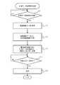
図4は、計測データ取得要求処理を示すフローチャートである。本処理は、データ収集装置2により実行される。データ収集装置2の点検記録部21は、各読取り装置1から計測データを取得する時期が到来したか判断する(S10)。 FIG. 4 is a flowchart showing the measurement data acquisition request process. This processing is executed by the
計測データの取得時期が到来したと判断された場合(S10:YES)、データ収集装置2の照度関連データ取得部22は、情報配信装置4または照度計5から照度関連データを取得する(S11)。データ収集装置2の露光調整情報生成部23は、照度関連データに基づいて、露光調整情報を生成する(S12)。 When it is determined that the acquisition time of the measurement data has arrived (S10: YES), the illuminance-related
点検記録部21は、計測データ取得要求を生成して、無線親局20から各無線子局10へ送信させる(S13)。この計測データ取得要求は、露光調整情報を含む。 The inspection recording unit 21 generates a measurement data acquisition request and causes the
各無線子局10は、図5で述べるように、計測データ取得要求を受信すると、読取り装置1を起動させる。読取り装置1は、露光調整情報に基づいた露光パラメータを用いて点検対象3を撮影し、その解析結果である計測データをデータ収集装置2へ送信する。 When receiving the measurement data acquisition request, each
データ収集装置2の点検記録部21は、各読取り装置1からの計測データを無線ネットワークを介して受信したことを知ると、計測データを計測データ記憶部24に保存させる(S15)。 When the inspection recording unit 21 of the
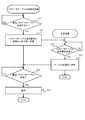
図5は、計測データ取得要求に対する応答である、データ要求応答処理のフローチャートを示す。本処理は、読取り装置1により実行される。 FIG. 5 shows a flowchart of the data request response process, which is a response to the measurement data acquisition request. This process is executed by the
読取り装置1は、計測データ取得要求を受信した無線子局10により、スリープ状態から起動される(S20:YES)。 The
露光パラメータ管理部13は、計測データ取得要求に含まれる露光調整情報に基づいて、露光パラメータテーブル131から露光パラメータを取得する(S21)。露光パラメータテーブル131に露光パラメータが登録されていない場合、露光パラメータ管理部13は初期値130を選択する(S21)。 The exposure
露光パラメータ管理部13は、ステップS21で選択した露光パラメータを計測部11に設定して起動させ、点検対象3を計測させる(S22)。すなわち、計測部11には、その起動時に露光パラメータが設定される。本実施例では、起動時に露光パラメータが設定されているため、計測部11は、露光調整を行う必要がなく、ただちに点検対象を計測することができる。 The exposure
計測部11で計測した生データ(画像データ)は、センサ情報解析部12により解析され、メータ値が読み取られる。センサ情報解析部12がメータ値を読み取ることができなかった場合(S23:NO)、計測部11は、露光パラメータを所定量調整して、再計測する(S24)。メータ値の読取りに成功するまで、ステップS23,S24が繰り返される。 Raw data (image data) measured by the
センサ情報解析部12がメータ値の正常な読取りに成功した場合(S23:YES)、露光パラメータ管理部13は、計測成功時の露光パラメータを露光パラメータテーブル131に保存する(S25)。センサ情報解析部12は、計測データ(読み取ったメータ値、計測時刻等を含む)を無線子局10から無線親局20に向けて送信させる。 When the sensor
図6は、メータ読取りに要する時間を比較する説明図である。図6(1)および(2)のグラフは、比較例の場合を示す。図6(3)および(4)のグラフは、本実施例の場合を示す。縦軸は消費電力を示し、横軸は時間を示す。 FIG. 6 is an explanatory diagram for comparing the time required for meter reading. The graphs of FIGS. 6A and 6B show the case of the comparative example. Graphs (3) and (4) of FIG. 6 show the case of this embodiment. The vertical axis represents power consumption, and the horizontal axis represents time.
図1(1),(3)に示すように、ここでの自動点検システムでは、毎日一回計測データを収集するものとする。計測データの収集間隔は一日単位に限らない。 As shown in FIGS. 1(1) and 1(3), the automatic inspection system here collects measurement data once a day. The measurement data collection interval is not limited to one day.
図1(2)は、図1(1)の計測時間T1を拡大して示す。点検対象3の一回の計測に要する時間T1は、撮影時間T11と露光調整時間T12とに分けることができる。最初に選択した露光パラメータを用いた撮影に失敗すると、露光パラメータが調整される。露光パラメータの調整後、再度撮影される。露光パラメータを調整してもなお撮影に失敗した場合は、再び露光パラメータが調整される。 FIG. 1(2) shows the measurement time T1 of FIG. 1(1) in an enlarged manner. The time T1 required for one measurement of the
図1(1),(2)に示す比較例では、一回の計測に際して、2回の露光調整と3回の撮影を行っている。すなわち、画像取得のリトライが複数発生している。一回の計測に要する時間T1は、例えば7秒であるとする。計測に要する時間T1の大部分は、露光調整時間T12で占められる。したがって、読取り装置1が一回の計測で消費する電力量は、露光調整の回数に強く依存する。 In the comparative example shown in FIGS. 1(1) and 1(2), exposure adjustment is performed twice and imaging is performed three times in one measurement. That is, a plurality of image acquisition retries have occurred. It is assumed that the time T1 required for one measurement is, for example, 7 seconds. Most of the time T1 required for measurement is occupied by the exposure adjustment time T12. Therefore, the amount of power consumed by the
これに対し本実施例では、図1(3)に示すように、一回の計測に要する時間T2は、比較例における計測時間T1よりも短くなる。本実施例では、露光パラメータ管理部13は、データ収集装置2から受信する露光調整情報を用いて露光パラメータを決定し、決定した露光パラメータを計測部11に設定した後で、計測部11を起動させる。これにより、本実施例では、計測部11が起動する際の露光調整を省略することができる。さらに、計測部11の起動時に設定される露光パラメータは、前回の計測時に成功した露光パラメータであるから、最初の撮影に成功する可能性が高くなる。したがって、本実施例では、適切な露光パラメータを使用する可能性が高く、計測のリトライ回数を低減することができ、その結果、読取り装置1の消費電力を低減して長期間の動作を実現できる。 On the other hand, in this embodiment, as shown in FIG. 1C, the time T2 required for one measurement is shorter than the measurement time T1 in the comparative example. In the present embodiment, the exposure
なお、図1(4)の右側に示すように、日照変化等により、起動時に設定した露光パラメータでは計測が成功しない場合もあり得る。その場合は、露光パラメータを調整した後で再計測する。再計測に成功すると、計測成功時の露光パラメータは、露光パラメータテーブル131に保存される。 Note that, as shown on the right side of FIG. 1(4), there is a possibility that the measurement may not be successful with the exposure parameter set at the time of startup due to changes in the sunshine. In that case, re-measurement is performed after adjusting the exposure parameters. When the re-measurement is successful, the exposure parameter at the time of successful measurement is stored in the exposure parameter table 131.
本実施例の自動点検システムによれば、運用を継続するほど、そのときの計測環境(明るさの程度)に適した露光パラメータが学習されて蓄積されていくため、読取り装置1の消費電力を抑制することができ、内蔵電池14の交換頻度を延ばすこともできる。 According to the automatic inspection system of the present embodiment, as the operation is continued, the exposure parameter suitable for the measurement environment (degree of brightness) at that time is learned and accumulated, so that the power consumption of the
起動時に設定した露光パラメータによって計測に成功した場合、計測時間T2を比較例に比べて大幅に短縮することができる。起動時に設定した露光パラメータでは失敗した場合でも、比較例に比べると、露光調整の平均回数は少なくなると考えられる。起動時に設定した露光パラメータは、前回の計測時に成功した値だからである。 When the measurement is successful with the exposure parameter set at startup, the measurement time T2 can be significantly shortened compared to the comparative example. Even if the exposure parameter set at startup fails, the average number of exposure adjustments is considered to be smaller than in the comparative example. This is because the exposure parameter set at startup is the value that was successful at the previous measurement.
なお、本実施例では、無線ネットワークに参加する全ての読取り装置1に、露光パラメータ管理部13を設ける場合を説明したが、これに限らず、一部の読取り装置1についてのみ露光パラメータを管理する構成でもよい。この構成も本発明の範囲に含まれる。例えば、天候や照明の状態による影響を受けやすい場所に設置された読取り装置1についてのみ露光パラメータを管理する構成でもよい。 In the present embodiment, the case where the exposure
図7〜図9を用いて、第2実施例を説明する。本実施例では、第1実施例との差異を中心に説明する。本実施例では、路好調情報毎、読取り装置1毎に適した露光パラメータを収集して、他の自動点検システムに利用する場合を説明する。あるいは、本実施例は、同一の自動点検システムにおいて、或る読取り装置1で蓄積された露光パラメータを、他の読取り装置1にコピーすることにより当該他の読取り装置1の消費電力を抑制する場合にも適用することができる。 A second embodiment will be described with reference to FIGS. 7 to 9. In this embodiment, the difference from the first embodiment will be mainly described. In this embodiment, a case will be described in which exposure parameters suitable for each road condition information and each
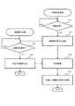
図7は、データ収集装置2が読取り装置1から露光パラメータテーブル131を取得する処理を示すフローチャートである。 FIG. 7 is a flowchart showing a process in which the
データ収集装置2の点検記録部21は、露光パラメータテーブル131の取得時期であるか判定する(S30)。データ収集装置2は、例えば、予め設定されたスケジュールにしたがって、各読取り装置1の全部または一部から露光パラメータテーブル131を取得することができる。または、データ収集装置2は、外部装置6から入力される指示にしたがって、露光パラメータテーブル131を取得することもできる。 The inspection recording unit 21 of the
点検記録部21は、露光パラメータテーブル131を取得する場合(S30:YES)、無線親局20から無線子局10を介して、取得対象の読取り装置1に対し、露光パラメータテーブル131の送信を要求する(S31)。 When the inspection recording unit 21 acquires the exposure parameter table 131 (S30: YES), the inspection recording unit 21 requests the
読取り装置1の露光パラメータ管理部13は、データ収集装置2からの要求を受信すると(S40:YES)、露光パラメータテーブル131を無線ネットワークを介してデータ収集装置2へ送信する(S41)。 Upon receiving the request from the data collection device 2 (S40: YES), the exposure
データ収集装置2の点検記録部21は、読取り装置1から露光パラメータテーブル131を受信すると(S32:YES)、そのテーブルを計測データ記憶部24へ記憶させる(S33)。露光パラメータテーブル131の記憶先は、計測データ記憶部24に限らず、他の記憶部でもよい。 When the inspection recording unit 21 of the
図8は、読取り装置1の露光パラメータテーブル131等を外部装置6等へ提供する処理を示すフローチャートである。 FIG. 8 is a flowchart showing a process of providing the exposure parameter table 131 and the like of the
ユーザは、外部装置6を介して情報提供部26へログインし、情報提供部26の提供するメニュー画面を外部装置6の表示装置(不図示)に表示させる。ユーザは、そのメニュー画面を操作することにより、データ収集装置2の提供する情報を利用する。ユーザが情報の利用を指示すると(S51:YES)、外部装置6からデータ収集装置2の情報提供部26へ情報提供要求が送信される。 The user logs in to the
情報提供部26は、外部装置6からの要求を受信すると(S60:YES)、露光パラメータテーブル131の内容を含む所定の情報260(図9で後述)を生成し、生成した所定の情報260を外部装置6へ送信する(S61)。 When the
外部装置6は、情報提供部26から所定の情報260を受信し(S53)、その所定の情報260を利用する(S54)。 The
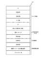
図9は、情報提供部26が外部装置6へ提供する所定の情報260の例を示す。所定の情報260は、例えば、センサ情報と、計測成功時の明るさに関する情報と、計測時期の情報と、無線通信品質の情報との全部または一部を含むことができる。さらに、所定の情報260は、図9に示されていない新たな情報を含んでもよい。 FIG. 9 shows an example of the
センサ情報には、例えば、読取り装置1を識別するための識別情報(ID)、読取り装置1の設置場所、点検対象3の種別や型式、読み取ったメータ値、読取り装置1の内蔵電池14の電池残量(SoC)等が含まれる。 The sensor information includes, for example, identification information (ID) for identifying the
計測成功時の明るさに関する情報には、例えば、露光調整情報毎の露光パラメータテーブル131の内容(図9中では、「明るさ(天候状態、照度)」と「露光パラメータ」として示す)、照明情報等が含まれる。 The information on the brightness at the time of successful measurement includes, for example, the contents of the exposure parameter table 131 for each exposure adjustment information (indicated as “brightness (weather condition, illuminance)” and “exposure parameter” in FIG. 9), and illumination. Information etc. are included.
計測時期の情報には、例えば、計測部11により点検対象3を計測した時刻を示す情報が含まれる。 The information on the measurement time includes, for example, information indicating the time at which the
無線通信品質の情報には、例えば、電波強度、無線ネットワークの再構成の頻度、パケットエラー率等が含まれる。 The information on the wireless communication quality includes, for example, radio wave intensity, frequency of wireless network reconfiguration, packet error rate, and the like.
ユーザは、所定の情報260を解析することにより、各読取り部1がどのような計測環境下および無線通信環境下において、どのようなタイミングで点検対象3を計測しているのか、さらには、読取り装置1の電池残量はどの程度かといった情報を把握することができる。 The user analyzes the
したがって、ユーザは、所定の情報260に基づいて、新規に設置予定の自動点検システムに含まれる各読取り装置1の露光パラメータテーブル131を調整し、調整された露光パラメータテーブル131を予め読取り装置1の露光パラメータ管理部13に設定することができる。このため、新規設定予定の自動点検システムでは、露光調整の試行錯誤を低減することができる。したがって、本実施例によれば、露光パラメータテーブル131の値が設定されていない場合に比べて、露光パラメータテーブル131を適切な値にするための学習期間を短縮でき、使い勝手が向上する。 Therefore, the user adjusts the exposure parameter table 131 of each
既存の自動点検システムに新たな読取り装置1を追加したり、古い読取り装置1を新たな読取り装置1に置き換えたりする場合も、同様の効果を得られる。すなわち、ユーザは、所定の情報260を参考にして、新たな読取り装置1に適切な露光パラメータテーブル131を用意し、新たな読取り装置1の露光パラメータ管理部13に記憶させることができる。 The same effect can be obtained when a
なお、本発明は、上述した実施形態に限定されない。当業者であれば、本発明の範囲内で、種々の追加や変更等を行うことができる。上述の実施形態において、添付図面に図示した構成例に限定されない。本発明の目的を達成する範囲内で、実施形態の構成や処理方法は適宜変更することが可能である。 The present invention is not limited to the above embodiment. A person skilled in the art can make various additions and changes within the scope of the present invention. The above embodiment is not limited to the configuration example illustrated in the accompanying drawings. The configuration and the processing method of the embodiment can be appropriately changed within the scope of achieving the object of the present invention.
また、本発明の各構成要素は、任意に取捨選択することができ、取捨選択した構成を具備する発明も本発明に含まれる。さらに特許請求の範囲に記載された構成は、特許請求の範囲で明示している組合せ以外にも組み合わせることができる。 Further, each component of the present invention can be arbitrarily selected, and the present invention also includes an invention having a selected configuration. Furthermore, the configurations described in the claims can be combined in addition to the combinations specified in the claims.
1:読取り装置、2:データ収集装置、3:点検対象、4:情報配信装置、5:照度計、6:外部装置、10:無線子局、11:計測部、12:センサ情報解析部、13:露光パラメータ管理部、14:内蔵電池、20:無線親局、21:点検記録部、22:照度関連データ取得部、23:露光調整情報生成部、24:計測データ記憶部、25:点検管理情報記憶部、26:情報提供部、100:計測データ取得要求、110:計測データ 1: reading device, 2: data collection device, 3: inspection target, 4: information distribution device, 5: illuminance meter, 6: external device, 10: wireless slave station, 11: measurement unit, 12: sensor information analysis unit, 13: exposure parameter management unit, 14: built-in battery, 20: wireless master station, 21: inspection recording unit, 22: illuminance-related data acquisition unit, 23: exposure adjustment information generation unit, 24: measurement data storage unit, 25: inspection Management information storage unit, 26: information providing unit, 100: measurement data acquisition request, 110: measurement data
Claims (7)
Translated fromJapanese前記計測装置は、
点検対象を計測するセンサ部と、
前記センサ部が前記点検対象を計測する際に用いる所定のパラメータを管理するパラメータ管理部であって、前記データ収集装置から受信するパラメータ決定用情報に基づいて前記センサ部に設定する前記所定のパラメータを決定するパラメータ管理部と、
前記センサ部が前記所定のパラメータを用いて前記点検対象を計測したデータを解析することにより、計測データを生成する計測データ生成部と、
を備え、
前記データ収集装置は、
前記パラメータ決定用情報を生成するパラメータ決定用情報生成部と、
前記計測装置に対し前記パラメータ決定用情報を明示して、計測データの取得を要求し、前記計測装置から取得した計測データを保存する計測データ取得部と、
を備える、
自動点検システム。An automatic inspection system comprising a measuring device that outputs measured data and a data collecting device that collects measured data from the measuring device,
The measuring device is
A sensor unit that measures the inspection target,
A parameter management unit that manages predetermined parameters used when the sensor unit measures the inspection target, and the predetermined parameters that are set in the sensor unit based on parameter determination information received from the data collection device. A parameter management unit that determines
A measurement data generation unit that generates measurement data by analyzing data in which the sensor unit measures the inspection target using the predetermined parameter,
Equipped with
The data collection device,
A parameter determination information generation unit that generates the parameter determination information,
A measurement data acquisition unit that explicitly indicates the parameter determination information to the measurement device, requests acquisition of measurement data, and saves the measurement data acquired from the measurement device,
With
Automatic inspection system.
前記複数の計測装置は、無線ネットワークを介して通信する無線子局にそれぞれ接続されており、
前記データ収集装置は、前記各計測装置に接続された前記各無線子局と前記無線ネットワークを介して通信する無線親局に接続されており、
前記各計測装置は、内蔵電源の電力を用いて動作し、
前記センサ部はカメラであり、かつ、前記所定のパラメータは露光時間である、
請求項1に記載の自動点検システム。There are multiple measuring devices,
The plurality of measuring devices are respectively connected to wireless slave stations that communicate via a wireless network,
The data collection device is connected to a wireless master station that communicates with each of the wireless slave stations connected to each of the measuring devices via the wireless network,
Each of the measuring devices operates using the power of the built-in power source,
The sensor unit is a camera, and the predetermined parameter is an exposure time,
The automatic inspection system according to claim 1.
前記調整された所定のパラメータを用いた場合の前記計測データ生成部によるデータ解析が成功したときには、前記パラメータ管理部は、前記調整された所定のパラメータを前記パラメータ決定用情報に対応づけて保存する、
請求項2に記載の自動点検システム。When the data analysis by the measurement data generation unit fails, the parameter management unit adjusts the predetermined parameter to be set in the sensor unit,
When the data analysis by the measurement data generation unit using the adjusted predetermined parameter is successful, the parameter management unit stores the adjusted predetermined parameter in association with the parameter determination information. ,
The automatic inspection system according to claim 2.
請求項3に記載の自動点検システム。The parameter management unit, when not storing a predetermined parameter corresponding to the parameter determination information received from the data collection device, sets an initial parameter stored in advance in the sensor unit,
The automatic inspection system according to claim 3.
請求項4に記載の自動点検システム。The data collection device collects the predetermined parameter stored in the parameter management unit in association with the parameter determination information from each of the measurement devices, and outputs the collected predetermined parameter to an external device. Further equipped with an information providing section to provide,
The automatic inspection system according to claim 4.
請求項5に記載の自動点検システム。The parameter determination information generation unit, at least one of the information acquired from the information distribution device connected via a communication network, or the information acquired from a predetermined measurement device included in each of the measurement devices. Generate the parameter determination information based on the information,
The automatic inspection system according to claim 5.
前記計算機は、
前記計測装置が点検対象を計測する際に用いる所定のパラメータを決定するパラメータ決定用情報を生成し、
前記生成したパラメータ決定用情報を明示して、前記計測装置に計測データの取得を要求し、
前記計測装置から取得した計測データを保存し、
前記計測装置は、
前記計算機から計測データの取得を要求されると、保存されている前記所定のパラメータの中から前記パラメータ決定用情報に対応する所定のパラメータを決定し、
前記決定された所定のパラメータを用いて前記点検対象を計測し、計測データを前記計算機へ送信し、
前記点検対象の計測に失敗した場合は、前記所定のパラメータを調整して前記点検対象を再計測し、
前記点検対象の計測に成功した場合は、前記所定のパラメータを前記パラメータ決定用情報に対応づけて保存する、
自動点検方法。An automatic inspection method that collects measurement data from a measuring device to a computer,
The calculator is
Generating parameter determination information for determining a predetermined parameter used when the measuring device measures an inspection target,
Explicitly indicating the generated parameter determination information, requesting the measurement device to acquire measurement data,
Save the measurement data obtained from the measuring device,
The measuring device is
When acquisition of measurement data is requested from the computer, a predetermined parameter corresponding to the parameter determination information is determined from among the predetermined parameters stored,
The inspection target is measured using the determined predetermined parameter, the measurement data is transmitted to the computer,
If the measurement of the inspection target fails, the predetermined parameter is adjusted to re-measure the inspection target,
When the measurement of the inspection target is successful, the predetermined parameter is stored in association with the parameter determination information,
Automatic inspection method.
Priority Applications (4)
| Application Number | Priority Date | Filing Date | Title |
|---|---|---|---|
| JP2017175507AJP6751062B2 (en) | 2017-09-13 | 2017-09-13 | Automatic inspection system and automatic inspection method |
| PCT/JP2018/021672WO2019053969A1 (en) | 2017-09-13 | 2018-06-06 | Automated inspection system and automated inspection method |
| US16/637,360US11276155B2 (en) | 2017-09-13 | 2018-06-06 | Automated inspection system and automated inspection method including a data collection device that generates exposure parameter determination information |
| CN201880059140.2ACN111066070A (en) | 2017-09-13 | 2018-06-06 | Automatic inspection system and automatic inspection method |
Applications Claiming Priority (1)
| Application Number | Priority Date | Filing Date | Title |
|---|---|---|---|
| JP2017175507AJP6751062B2 (en) | 2017-09-13 | 2017-09-13 | Automatic inspection system and automatic inspection method |
Publications (2)
| Publication Number | Publication Date |
|---|---|
| JP2019053380A JP2019053380A (en) | 2019-04-04 |
| JP6751062B2true JP6751062B2 (en) | 2020-09-02 |
Family
ID=65723282
Family Applications (1)
| Application Number | Title | Priority Date | Filing Date |
|---|---|---|---|
| JP2017175507AActiveJP6751062B2 (en) | 2017-09-13 | 2017-09-13 | Automatic inspection system and automatic inspection method |
Country Status (4)
| Country | Link |
|---|---|
| US (1) | US11276155B2 (en) |
| JP (1) | JP6751062B2 (en) |
| CN (1) | CN111066070A (en) |
| WO (1) | WO2019053969A1 (en) |
Families Citing this family (3)
| Publication number | Priority date | Publication date | Assignee | Title |
|---|---|---|---|---|
| JP6751062B2 (en)* | 2017-09-13 | 2020-09-02 | 株式会社日立製作所 | Automatic inspection system and automatic inspection method |
| US20240142386A1 (en)* | 2021-03-01 | 2024-05-02 | Leica Microsystems (Suzhou) Technology Co., Ltd. | Processing device, inspection apparatus and system for optical inspection and corresponding methods |
| JP7546516B2 (en)* | 2021-06-02 | 2024-09-06 | 三菱電機株式会社 | Inspection support system, inspection support method, and learning device |
Family Cites Families (24)
| Publication number | Priority date | Publication date | Assignee | Title |
|---|---|---|---|---|
| US4420564A (en)* | 1980-11-21 | 1983-12-13 | Fuji Electric Company, Ltd. | Blood sugar analyzer having fixed enzyme membrane sensor |
| EP0700515B1 (en)* | 1993-05-28 | 2000-09-06 | Millennium Venture Holdings Ltd. | An automatic inspection apparatus |
| US6546308B2 (en)* | 1993-12-28 | 2003-04-08 | Hitachi, Ltd, | Method and system for manufacturing semiconductor devices, and method and system for inspecting semiconductor devices |
| JP2002288780A (en) | 2001-03-28 | 2002-10-04 | Mitsubishi Electric Corp | Automatic meter reading device and measurement system using the same |
| JP3870044B2 (en)* | 2001-07-25 | 2007-01-17 | 株式会社日立製作所 | Pattern inspection method and pattern inspection apparatus |
| JP4032680B2 (en)* | 2001-08-24 | 2008-01-16 | 三菱電機株式会社 | Monitoring device |
| JP3674569B2 (en)* | 2001-10-04 | 2005-07-20 | オムロン株式会社 | SENSOR MANAGEMENT DEVICE, SENSOR MANAGEMENT DEVICE CONTROL PROGRAM, COMPUTER-READABLE RECORDING MEDIUM CONTAINING THE PROGRAM, AND SENSOR MANAGEMENT DEVICE CONTROL METHOD |
| CA2430737C (en)* | 2003-06-02 | 2011-12-20 | Centre De Recherche Industrielle Du Quebec | Method and apparatus for estimating surface moisture content of wood chips |
| JP2005085193A (en)* | 2003-09-11 | 2005-03-31 | Mitsubishi Materials Corp | Radio sensor system |
| US20070194913A1 (en) | 2003-09-11 | 2007-08-23 | Mitsubishi Materials Corporation | Wireless module,wireless temperature sensor,wireless interface device,and wireless sensor system |
| CN100422769C (en)* | 2003-11-24 | 2008-10-01 | 护照系统公司 | Adaptive material scanning using nuclear resonance fluorescence imaging |
| JP4592311B2 (en) | 2004-03-23 | 2010-12-01 | 中国電力株式会社 | Indication value recognition method, indication value recognition system, indication value recognition program, and recording medium on which indication value recognition program is recorded |
| JP3886014B2 (en)* | 2005-02-14 | 2007-02-28 | 株式会社エクセディ | Automatic ultrasonic inspection apparatus, inspection method thereof, and manufacturing method using the inspection method |
| EP2665035A3 (en)* | 2009-02-20 | 2016-12-07 | Werth Messtechnik GmbH | Method for measuring an object |
| JP5475373B2 (en)* | 2009-09-11 | 2014-04-16 | 株式会社電工社 | Automatic meter reading system |
| DE102009060500B4 (en)* | 2009-12-22 | 2015-12-17 | Xion Gmbh | A method for stroboscopically examining repetitive processes and arrangement for operating this method |
| WO2013155467A1 (en)* | 2012-04-13 | 2013-10-17 | View, Inc. | Applications for controlling optically switchable devices |
| CN103959043B (en)* | 2011-05-31 | 2016-11-02 | 光学实验室成像公司 | Multimodal imaging systems, devices and methods |
| US8646692B2 (en)* | 2011-09-30 | 2014-02-11 | Hand Held Products, Inc. | Devices and methods employing dual target auto exposure |
| JP6237103B2 (en)* | 2013-10-17 | 2017-11-29 | 富士通株式会社 | Information collection device, information collection method, and information collection program |
| WO2017102336A1 (en)* | 2015-12-18 | 2017-06-22 | Asml Netherlands B.V. | Improvements in gauge pattern selection |
| US10145752B2 (en)* | 2016-01-21 | 2018-12-04 | Horiba, Ltd. | Management apparatus for measurement equipment |
| JP6751062B2 (en)* | 2017-09-13 | 2020-09-02 | 株式会社日立製作所 | Automatic inspection system and automatic inspection method |
| US10996352B2 (en)* | 2018-09-29 | 2021-05-04 | David Edward Newman | Imaging radiation detector array |
- 2017
- 2017-09-13JPJP2017175507Apatent/JP6751062B2/enactiveActive
- 2018
- 2018-06-06CNCN201880059140.2Apatent/CN111066070A/enactivePending
- 2018-06-06USUS16/637,360patent/US11276155B2/enactiveActive
- 2018-06-06WOPCT/JP2018/021672patent/WO2019053969A1/ennot_activeCeased
Also Published As
| Publication number | Publication date |
|---|---|
| WO2019053969A1 (en) | 2019-03-21 |
| JP2019053380A (en) | 2019-04-04 |
| CN111066070A (en) | 2020-04-24 |
| US20200357107A1 (en) | 2020-11-12 |
| US11276155B2 (en) | 2022-03-15 |
Similar Documents
| Publication | Publication Date | Title |
|---|---|---|
| US10444033B2 (en) | Meter reading device and system | |
| US11238673B2 (en) | Automatic inspection system and method for controlling automatic inspection system | |
| US7860672B2 (en) | Method and apparatus for monitoring voltage in a meter network | |
| CN109446032A (en) | Method and system for Kubernetes replica expansion and contraction | |
| JP6751062B2 (en) | Automatic inspection system and automatic inspection method | |
| WO2018123270A1 (en) | Automatic inspection system and automatic inspection method | |
| JP7073952B2 (en) | Data collection system and data collection method | |
| JP2009002914A (en) | Facility damage monitoring apparatus and facility damage monitoring method | |
| KR101052081B1 (en) | Remote metering terminal, remote metering system and control method using the same | |
| WO2018061326A1 (en) | Automatic inspection system, object to be inspected reading device for automatic inspection system, and automatic inspection system control method | |
| CN116882662B (en) | Smart park management method, device, management system and storage medium | |
| CN203135930U (en) | Substation double-vision on-line monitoring intelligent early-warning system | |
| CN103167313B (en) | Video monitoring service quality measuring method, system and quality measuring server | |
| US10769767B2 (en) | Monitoring system and its control method | |
| KR20120109169A (en) | Remote inspection of a meter reading based on photographing means and device for remote inspection using a remote inspection of a meter reading based on photographing means and method thereof | |
| CN208581240U (en) | A portable terminal signal tester | |
| WO2018123298A1 (en) | Automated inspection system and automated inspection method | |
| CN111599446A (en) | Management method of medical display equipment and related equipment | |
| CN114239634A (en) | Data processing method, device and medium for spot inspection of industrial equipment | |
| CN117876648A (en) | Meter identification method and system | |
| JPWO2019008890A1 (en) | Central processing unit and method for monitored person monitoring support system and monitored person monitoring support system | |
| KR101121128B1 (en) | Remote meter reader | |
| JP2022161337A (en) | Information processing device, information processing method, and program | |
| KR20190035014A (en) | Measurement system | |
| CN117370428A (en) | Data processing method, device and storage medium |
Legal Events
| Date | Code | Title | Description |
|---|---|---|---|
| A621 | Written request for application examination | Free format text:JAPANESE INTERMEDIATE CODE: A621 Effective date:20200120 | |
| TRDD | Decision of grant or rejection written | ||
| A01 | Written decision to grant a patent or to grant a registration (utility model) | Free format text:JAPANESE INTERMEDIATE CODE: A01 Effective date:20200721 | |
| A61 | First payment of annual fees (during grant procedure) | Free format text:JAPANESE INTERMEDIATE CODE: A61 Effective date:20200813 | |
| R150 | Certificate of patent or registration of utility model | Ref document number:6751062 Country of ref document:JP Free format text:JAPANESE INTERMEDIATE CODE: R150 |