JP6750768B1 - Muscle activity observation device and muscle activity observation method - Google Patents
Muscle activity observation device and muscle activity observation methodDownload PDFInfo
- Publication number
- JP6750768B1 JP6750768B1JP2020528189AJP2020528189AJP6750768B1JP 6750768 B1JP6750768 B1JP 6750768B1JP 2020528189 AJP2020528189 AJP 2020528189AJP 2020528189 AJP2020528189 AJP 2020528189AJP 6750768 B1JP6750768 B1JP 6750768B1
- Authority
- JP
- Japan
- Prior art keywords
- signal
- muscle
- sensor
- contraction
- tendon
- Prior art date
- Legal status (The legal status is an assumption and is not a legal conclusion. Google has not performed a legal analysis and makes no representation as to the accuracy of the status listed.)
- Active
Links
Images


Classifications
- G—PHYSICS
- G16—INFORMATION AND COMMUNICATION TECHNOLOGY [ICT] SPECIALLY ADAPTED FOR SPECIFIC APPLICATION FIELDS
- G16H—HEALTHCARE INFORMATICS, i.e. INFORMATION AND COMMUNICATION TECHNOLOGY [ICT] SPECIALLY ADAPTED FOR THE HANDLING OR PROCESSING OF MEDICAL OR HEALTHCARE DATA
- G16H40/00—ICT specially adapted for the management or administration of healthcare resources or facilities; ICT specially adapted for the management or operation of medical equipment or devices
- G16H40/60—ICT specially adapted for the management or administration of healthcare resources or facilities; ICT specially adapted for the management or operation of medical equipment or devices for the operation of medical equipment or devices
- G16H40/67—ICT specially adapted for the management or administration of healthcare resources or facilities; ICT specially adapted for the management or operation of medical equipment or devices for the operation of medical equipment or devices for remote operation
- A—HUMAN NECESSITIES
- A61—MEDICAL OR VETERINARY SCIENCE; HYGIENE
- A61B—DIAGNOSIS; SURGERY; IDENTIFICATION
- A61B5/00—Measuring for diagnostic purposes; Identification of persons
- A61B5/103—Measuring devices for testing the shape, pattern, colour, size or movement of the body or parts thereof, for diagnostic purposes
- A61B5/11—Measuring movement of the entire body or parts thereof, e.g. head or hand tremor or mobility of a limb
- A61B5/1101—Detecting tremor
- A—HUMAN NECESSITIES
- A61—MEDICAL OR VETERINARY SCIENCE; HYGIENE
- A61B—DIAGNOSIS; SURGERY; IDENTIFICATION
- A61B5/00—Measuring for diagnostic purposes; Identification of persons
- A61B5/103—Measuring devices for testing the shape, pattern, colour, size or movement of the body or parts thereof, for diagnostic purposes
- A61B5/11—Measuring movement of the entire body or parts thereof, e.g. head or hand tremor or mobility of a limb
- A61B5/1107—Measuring contraction of parts of the body, e.g. organ or muscle
- A—HUMAN NECESSITIES
- A61—MEDICAL OR VETERINARY SCIENCE; HYGIENE
- A61B—DIAGNOSIS; SURGERY; IDENTIFICATION
- A61B5/00—Measuring for diagnostic purposes; Identification of persons
- A61B5/22—Ergometry; Measuring muscular strength or the force of a muscular blow
- A61B5/224—Measuring muscular strength
- A—HUMAN NECESSITIES
- A61—MEDICAL OR VETERINARY SCIENCE; HYGIENE
- A61B—DIAGNOSIS; SURGERY; IDENTIFICATION
- A61B5/00—Measuring for diagnostic purposes; Identification of persons
- A61B5/68—Arrangements of detecting, measuring or recording means, e.g. sensors, in relation to patient
- A61B5/6801—Arrangements of detecting, measuring or recording means, e.g. sensors, in relation to patient specially adapted to be attached to or worn on the body surface
- A61B5/6813—Specially adapted to be attached to a specific body part
- A61B5/6829—Foot or ankle
- A—HUMAN NECESSITIES
- A61—MEDICAL OR VETERINARY SCIENCE; HYGIENE
- A61B—DIAGNOSIS; SURGERY; IDENTIFICATION
- A61B5/00—Measuring for diagnostic purposes; Identification of persons
- A61B5/72—Signal processing specially adapted for physiological signals or for diagnostic purposes
- A61B5/7271—Specific aspects of physiological measurement analysis
- A61B5/7278—Artificial waveform generation or derivation, e.g. synthesizing signals from measured signals
- G—PHYSICS
- G01—MEASURING; TESTING
- G01D—MEASURING NOT SPECIALLY ADAPTED FOR A SPECIFIC VARIABLE; ARRANGEMENTS FOR MEASURING TWO OR MORE VARIABLES NOT COVERED IN A SINGLE OTHER SUBCLASS; TARIFF METERING APPARATUS; MEASURING OR TESTING NOT OTHERWISE PROVIDED FOR
- G01D5/00—Mechanical means for transferring the output of a sensing member; Means for converting the output of a sensing member to another variable where the form or nature of the sensing member does not constrain the means for converting; Transducers not specially adapted for a specific variable
- G01D5/12—Mechanical means for transferring the output of a sensing member; Means for converting the output of a sensing member to another variable where the form or nature of the sensing member does not constrain the means for converting; Transducers not specially adapted for a specific variable using electric or magnetic means
- G01D5/14—Mechanical means for transferring the output of a sensing member; Means for converting the output of a sensing member to another variable where the form or nature of the sensing member does not constrain the means for converting; Transducers not specially adapted for a specific variable using electric or magnetic means influencing the magnitude of a current or voltage
- G01D5/18—Mechanical means for transferring the output of a sensing member; Means for converting the output of a sensing member to another variable where the form or nature of the sensing member does not constrain the means for converting; Transducers not specially adapted for a specific variable using electric or magnetic means influencing the magnitude of a current or voltage by varying effective impedance of discharge tubes or semiconductor devices
- G01D5/183—Sensing rotation or linear movement using strain, force or pressure sensors
- G01D5/185—Sensing rotation or linear movement using strain, force or pressure sensors using piezoelectric sensors
- G—PHYSICS
- G01—MEASURING; TESTING
- G01L—MEASURING FORCE, STRESS, TORQUE, WORK, MECHANICAL POWER, MECHANICAL EFFICIENCY, OR FLUID PRESSURE
- G01L1/00—Measuring force or stress, in general
- G01L1/16—Measuring force or stress, in general using properties of piezoelectric devices
- G—PHYSICS
- G16—INFORMATION AND COMMUNICATION TECHNOLOGY [ICT] SPECIALLY ADAPTED FOR SPECIFIC APPLICATION FIELDS
- G16H—HEALTHCARE INFORMATICS, i.e. INFORMATION AND COMMUNICATION TECHNOLOGY [ICT] SPECIALLY ADAPTED FOR THE HANDLING OR PROCESSING OF MEDICAL OR HEALTHCARE DATA
- G16H20/00—ICT specially adapted for therapies or health-improving plans, e.g. for handling prescriptions, for steering therapy or for monitoring patient compliance
- G16H20/30—ICT specially adapted for therapies or health-improving plans, e.g. for handling prescriptions, for steering therapy or for monitoring patient compliance relating to physical therapies or activities, e.g. physiotherapy, acupressure or exercising
- A—HUMAN NECESSITIES
- A61—MEDICAL OR VETERINARY SCIENCE; HYGIENE
- A61B—DIAGNOSIS; SURGERY; IDENTIFICATION
- A61B2560/00—Constructional details of operational features of apparatus; Accessories for medical measuring apparatus
- A61B2560/04—Constructional details of apparatus
- A61B2560/0475—Special features of memory means, e.g. removable memory cards
- A—HUMAN NECESSITIES
- A61—MEDICAL OR VETERINARY SCIENCE; HYGIENE
- A61B—DIAGNOSIS; SURGERY; IDENTIFICATION
- A61B2562/00—Details of sensors; Constructional details of sensor housings or probes; Accessories for sensors
- A61B2562/02—Details of sensors specially adapted for in-vivo measurements
- A61B2562/0204—Acoustic sensors
- A—HUMAN NECESSITIES
- A61—MEDICAL OR VETERINARY SCIENCE; HYGIENE
- A61B—DIAGNOSIS; SURGERY; IDENTIFICATION
- A61B2562/00—Details of sensors; Constructional details of sensor housings or probes; Accessories for sensors
- A61B2562/02—Details of sensors specially adapted for in-vivo measurements
- A61B2562/0219—Inertial sensors, e.g. accelerometers, gyroscopes, tilt switches
- A—HUMAN NECESSITIES
- A61—MEDICAL OR VETERINARY SCIENCE; HYGIENE
- A61B—DIAGNOSIS; SURGERY; IDENTIFICATION
- A61B2562/00—Details of sensors; Constructional details of sensor housings or probes; Accessories for sensors
- A61B2562/06—Arrangements of multiple sensors of different types
Landscapes
- Health & Medical Sciences (AREA)
- Life Sciences & Earth Sciences (AREA)
- Engineering & Computer Science (AREA)
- Biomedical Technology (AREA)
- Public Health (AREA)
- Medical Informatics (AREA)
- General Health & Medical Sciences (AREA)
- Physics & Mathematics (AREA)
- Biophysics (AREA)
- Veterinary Medicine (AREA)
- Pathology (AREA)
- Heart & Thoracic Surgery (AREA)
- Molecular Biology (AREA)
- Surgery (AREA)
- Animal Behavior & Ethology (AREA)
- Physiology (AREA)
- Dentistry (AREA)
- Oral & Maxillofacial Surgery (AREA)
- Physical Education & Sports Medicine (AREA)
- Epidemiology (AREA)
- Primary Health Care (AREA)
- General Physics & Mathematics (AREA)
- Signal Processing (AREA)
- Psychiatry (AREA)
- Computer Vision & Pattern Recognition (AREA)
- Artificial Intelligence (AREA)
- Business, Economics & Management (AREA)
- General Business, Economics & Management (AREA)
- Measurement Of The Respiration, Hearing Ability, Form, And Blood Characteristics Of Living Organisms (AREA)
- Measurement And Recording Of Electrical Phenomena And Electrical Characteristics Of The Living Body (AREA)
Abstract
Translated fromJapaneseDescription
Translated fromJapanese本発明は、筋肉の活動を観測する筋活動観測の技術に関する。 The present invention relates to a muscle activity observation technique for observing muscle activity.
特許文献1に記載の筋肉動検出装置は、センサとコントローラとを備える。センサの電気抵抗は、筋肉の動きに伴う収縮によって変化する。コントローラは、センサの電気抵抗によって、筋肉動に応じた電圧を検出する。 The muscle motion detecting device described in
しかしながら、特許文献1に記載の筋肉動検出装置では、等張性収縮と等尺性収縮とを区別して計測できない。このため、筋肉の活動を正確に把握することは困難である。 However, the muscle motion detecting device described in
したがって、本発明の目的は、等張性収縮と等尺性収縮とを区別して観測できる筋活動観測技術を提供することにある。 Therefore, an object of the present invention is to provide a muscle activity observation technique capable of observing isotonic contractions and isometric contractions separately.
この発明の筋活動観測装置は、第1センサ、第2センサ、および、検出部を備える。第1センサは、腱または筋の振動によって出力が変化する。第2センサは、腱または筋の伸縮によって出力が変化する。検出部は、第1センサの出力信号と第2センサの出力信号とを用いて、腱または筋の活動状態を検出する。 The muscle activity observation device of the present invention includes a first sensor, a second sensor, and a detection unit. The output of the first sensor changes due to vibration of the tendon or muscle. The output of the second sensor changes as the tendon or muscle expands and contracts. The detection unit detects the activity state of the tendon or muscle using the output signal of the first sensor and the output signal of the second sensor.
この構成では、第1センサによって、腱または筋の振戦による信号(振戦信号)が得られる。また、第2センサによって、腱または筋の伸び縮みによる信号(伸縮信号)が得られる。そして、これら振戦信号と伸縮信号とが個別に得られることで、等尺性収縮の状態と等張性収縮の状態が個別に識別可能になる。 In this configuration, a signal (tremor signal) due to tremor of the tendon or muscle is obtained by the first sensor. In addition, the second sensor obtains a signal (expansion/contraction signal) due to expansion/contraction of the tendon or muscle. By separately obtaining the tremor signal and the expansion/contraction signal, the isometric contraction state and the isotonic contraction state can be individually identified.
この発明によれば、等張性収縮と等尺性収縮とを区別して観測できる。これにより、腱または筋の活動や状態がより正確に把握可能になる。 According to this invention, isotonic contraction and isometric contraction can be distinguished and observed. This makes it possible to more accurately grasp the activity or condition of the tendon or muscle.
(第1の実施形態)
本発明の第1の実施形態に係る筋活動観測装置について、図を参照して説明する。図1は、第1の実施形態に係る筋活動観測装置の構成を示すブロック図である。(First embodiment)
A muscle activity observation apparatus according to the first embodiment of the present invention will be described with reference to the drawings. FIG. 1 is a block diagram showing the configuration of the muscle activity observation apparatus according to the first embodiment.
(筋活動観測装置の機能ブロックの構成)
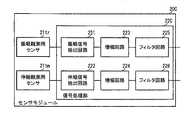
図1に示すように、筋活動観測装置10は、センサモジュール20、および、検出モジュール30を備える。センサモジュール20は、圧電センサ21、および、信号処理部22を備える。検出モジュール30は、検出部31、通信部32、および、電源33を備える。(Structure of functional block of muscle activity observation device)
As shown in FIG. 1, the muscle
圧電センサ21は、生体の腱または筋の活動に応じて変位する。圧電体201は、この変位に応じた電荷(電位差)を発生する。信号処理部22は、圧電センサ21が検出した電荷を電圧信号に変換することで、振戦信号と伸縮信号とを生成する。信号処理部22は、振戦信号と伸縮信号とを、検出部31に出力する。 The
検出部31は、振戦信号から振戦の状態を検出し、伸縮信号から伸縮の状態を検出する。また、検出部31は、振戦の状態および伸縮の状態から、生体の対象部位(例えば、足)の動作を解析する。 The
なお、本願における振戦とは、律動的な筋活動を示す不随意運動である。すなわち、本願における振戦は、正常人にみられる細かく速い姿勢時振戦であり、生理的振戦とよばれ、例えば、8Hzから12Hzの周波数である。なお、パーキンソン病患者等の疾患者にみられるふるえは、病理的振戦であり、例えば、4Hzから7Hzであり、本願における振戦の対象とはしない。 In addition, the tremor in this application is an involuntary movement which shows rhythmic muscle activity. That is, the tremor in the present application is a fine and fast posture tremor seen in a normal person, and is called physiological tremor, and has a frequency of, for example, 8 Hz to 12 Hz. The tremor seen in patients with Parkinson's disease and the like is pathological tremor, for example, 4 Hz to 7 Hz, and is not the subject of tremor in the present application.
振戦を用いることによって、筋電に対して、次の各種の優位点がある。例えば、振戦の検出(計測)は、人の体等の被検知体の表面(皮膚等)に直接貼り付けなくても可能である。振戦の検出によって、筋伸縮を検出できる。振戦の検出によって、筋疲労に伴う変化を検出できる。 The use of tremors has the following various advantages over EMG. For example, tremor can be detected (measured) without directly attaching it to the surface (skin or the like) of a detected object such as a human body. Stretching can be detected by tremor detection. By detecting a tremor, it is possible to detect a change associated with muscle fatigue.
通信部32は、振戦の状態、伸縮の状態、生体の対象部位の動作等の検出結果を、外部に通信する。通信方式は、無線であっても有線であってもよい。電源33は、検出部31、および、通信部32に電源供給する。なお、電源33は、センサモジュール20の信号処理部22にも電源供給できる。ただし、センサモジュール20は、電源33とは別に電源を備えていてもよい。 The
(筋活動観測装置の装着の一態様)
筋活動観測装置10は、例えば、次に示すように、上述の生体の対象部位に装着される。図2(A)は、筋活動観測装置の足への装着の状態を示す側面図であり、図2(B)は、筋活動観測装置の足への装着状態を示す平面図である。(One mode of wearing a muscle activity observation device)
The muscle
図2(A)、図2(B)に示すように、筋活動観測装置10は、生体支持体40を備える。生体支持体40は、伸縮性を有する素材からなり、生体の動きに合わせて変形する。生体支持体40は、圧電センサ21の変位(より具体的には、圧電センサ21の圧電体201(図4参照)の変位)を可能な限り阻害しない素材であることが好ましい。例えば、綿アクリル混、ポリエステル綿混、綿麻混、アクリル毛混、毛ナイロン混、獣毛混、絹、絹紡糸、絹紬糸(絹紡紬糸)等が使用可能である。 As shown in FIGS. 2A and 2B, the muscle
生体支持体40は、第1部分41および第2部分42を備える。第1部分41および第2部分42は、筒状であり、側面視して略L字状に繋がっている。第1部分41と第2部分42と繋ぎ目には、筒状の中空を外部に連通する穴43が形成されている。 The
図4(A)、図4(B)に示すように、生体支持体40は、各腱や筋が内蔵された足の踵93の近傍に、生体(人体)の外形に合わせて装着される。この際、第1部分41は、足首91を覆う。第2部分42は、足の甲92と足の裏94とを覆う。そして、踵93は、穴43から外部に露出している。 As shown in FIG. 4(A) and FIG. 4(B), the living
圧電センサ21は、第1部分41に装着されている。より具体的には、圧電センサ21は、第1部分41への接着材による接着、第1部分41への縫い付け、第1部分41に設けられたポケットへの収容等によって、第1部分41に装着されている。この際、圧電センサ21は、第1部分41の内側(中空側)に装着されていることが好ましい。 The
また、圧電センサ21は、第1部分41におけるアキレス腱901に重なる位置に配置されている。特に、圧電センサ21は、下腿最小囲90に重なる位置に配置されることが好ましい。このような位置に配置されることによって、圧電センサ21は、アキレス腱901の振戦および伸縮による電荷の発生の感度を良くできる。 Further, the
さらに、圧電センサ21の長さ方向(L方向)は、アキレス腱901の延びる方向に対して略直交している。後述する図3、図4に示す構造の圧電センサ21では、長さ方向(L方向)に対する変位が、最も電荷を発生させ易い。これにより、圧電センサ21は、アキレス腱901の伸縮を高感度で検出できる。 Furthermore, the length direction (L direction) of the
なお、ここでは、アキレス腱901の振戦および伸縮を検出する態様を示した。しかしながら、前脛骨筋腱902の振戦および伸縮を検出する場合には、圧電センサ21を前頸骨筋腱902に重ねればよい。また、長腓骨筋腱903の振戦および伸縮を検出する場合には、圧電センサ21を長腓骨筋腱903に重ねればよい。この際、圧電センサ21の長さ方向(L方向)は、腱の延びる方向にできる限り直交するとよい。 In addition, here, the mode of detecting tremor and expansion/contraction of the
また、生体支持体40が足の甲92および足の裏94と足首91とを支持し、途中で曲がっていることにより、生体支持体40と足との位置関係が変化し難い。したがって、圧電センサ21の位置は、変化し難く、圧電センサ21は、振戦および伸縮の検出対象の腱(ここではアキレス腱901)に対して、位置ズレし難い。これにより、圧電センサ21は、検出対象の腱の振戦および伸縮を、より確実に検出できる。 Further, since the
検出モジュール30は、生体支持体40に装着されている。検出モジュール30は、生体支持体40のいずれの位置に装着されていてもよい。しかしながら、検出モジュール30の装着位置は、外部との通信環境が容易な位置であることが好ましく、例えば、第1部分41における外側で、筒状の延びる方向における第2部分42に繋がる側と反対側の端部付近であることが好ましい。なお、検出モジュール30と、センサモジュール20とは、所定のケーブルによって接続されている。 The
(センサモジュール20の構造)
図3(A)は、センサモジュールの概略構成を示す側面図であり、図3(B)は、センサモジュールの概略構成を示す平面図である。(Structure of sensor module 20)
FIG. 3A is a side view showing a schematic configuration of the sensor module, and FIG. 3B is a plan view showing a schematic configuration of the sensor module.
図3(A)、図3(B)に示すように、センサモジュール20は、平膜状である。センサモジュール20は、平膜状の圧電センサ21、薄型の信号処理回路モジュール22M、平膜状の伝送ケーブル220C、および、接続端子220Mを備える。 As shown in FIGS. 3A and 3B, the
圧電センサ21は、長さLpと幅Wpとを有する略矩形のシート状である。長さLpは、幅Wpよりも大きい(Lp>Wp)。信号処理回路モジュール22Mは、信号処理部22を構成する電子部品と基材とによって形成されており、図3(A)、図3(B)においては具体的な電子部品の構造等は省略している。信号処理回路モジュール22Mは、圧電センサ21に並んで配置されており、フラットケーブル等によって圧電センサ21に接続されている。伝送ケーブル220Cにおける延びる方向の一方端は、信号処理回路モジュール22Mに接続されている。伝送ケーブル220Cにおける延びる方向の他方端には、導体からなる接続端子220Mが形成されている。 The
(圧電センサ21の構造および出力信号)
図4は、圧電センサの概略構成を示す側面断面図である。図4に示すように、圧電センサ21は、圧電体201、検出用電極202、接着層203、および、補助板204を備える。(Structure and output signal of the piezoelectric sensor 21)
FIG. 4 is a side sectional view showing a schematic configuration of the piezoelectric sensor. As shown in FIG. 4, the
圧電体201は、主面を有する矩形のフィルムである。例えば、圧電体201の長さLpは約40mm、幅Wpは約10mm、厚さは0.3mm未満である。なお、圧電体201の寸法はこれに限らず、観測対象に応じて適宜設定できる。圧電体201は、例えば、ポリ乳酸(PLLA)を主成分とする材料、あるいは、窒化アルミニウム(AlN)を主成分とする材料から構成されている。 The
検出用電極202は、接着層203を用いて、圧電体201の両主面にそれぞれ接着されている。検出用電極202は、例えば銅(Cu)等の導電率が高い材料であることが好ましい。接着層203は、可能な限り薄いことが好ましい。 The
補助板204は、検出用電極202における圧電体201と反対側に配置されている。この際、補助板204の主面と圧電体201の主面とは平行である。 The
このような構成では、例えば、圧電体201の主面に直交する方向における曲げの変位が発生すると、2つの検出用電極202にそれぞれ逆特性の電荷が発生する。この電荷量によって、2つの検出用電極202間には、図5に示すような電圧が生じる。図5は、圧電体201の曲げの変位と電圧との関係を示すグラフである。このように、圧電センサ21の電圧、すなわち、電荷量を検出することによって、圧電センサ21の曲げの変位を検出できる。そして、上述の図2に示すように、圧電センサ21を配置することで、アキレス腱901の伸縮による圧電センサ21の装着面の変形によって、圧電センサ21には曲げの変位が生じる。したがって、圧電センサ21の電圧を検出することで、アキレス腱901の伸縮を検出できる。 In such a configuration, for example, when bending displacement occurs in a direction orthogonal to the main surface of the
さらに、圧電センサ21の圧電体201は、微小な振動によっても電荷を発生する。圧電センサ21の電圧を検出することで、アキレス腱901の伸縮のみでなく、アキレス腱901の振戦も検出できる。これにより、腱や筋の伸縮の検出用のセンサと、腱や筋の振戦の検出用のセンサとを、個別に設けなくてもよい。この結果、腱や筋の伸縮と振戦とを検出可能なセンサを、簡素な構成によって実現できる。 Furthermore, the
また、補助板204が次の特性を有するとよりよい。補助板204は、圧電体201よりも硬ければよい。ここで、硬いとは、曲がり難さを表す指標である。例えば、補助板204の曲げ弾性率は、圧電体201の曲げ弾性率よりも高い。また、他の指標としては、圧電体201が上述の材料である場合に、補助板204のヤング率は、4GPa程度であるとよい。この際、補助板204の曲げ弾性率やヤング率は、圧電体201のみで補助板204を用いない態様よりも、補助板204を用いる態様の方が、同じ振動の大きさに対する電荷の発生量が多くなるように、設定すればよい。 Further, it is more preferable that the
これにより、圧電センサ21は、アキレス腱901の振戦を、より高感度に検出できる。 Accordingly, the
(信号処理部22の構成および処理)
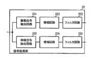
図6は、信号処理部の構成を示すブロック図である。図6に示すように、信号処理部22は、振戦信号抽出回路221、伸縮信号抽出回路222、増幅回路223、増幅回路224、フィルタ回路225、および、フィルタ回路226を備える。(Structure and Processing of Signal Processing Unit 22)
FIG. 6 is a block diagram showing the configuration of the signal processing unit. As shown in FIG. 6, the
振戦信号抽出回路221および伸縮信号抽出回路222は、それぞれ、チャージアンプ回路によって構成されている。この際、振戦信号抽出回路221のチャージアンプの時定数は、振戦信号の抽出用に設定されている。また、伸縮信号抽出回路222のチャージアンプの時定数は、伸縮信号の抽出用に設定されている。例えば、振戦信号抽出回路221のチャージアンプの時定数は、伸縮信号抽出回路222のチャージアンプの時定数よりも小さい。 The tremor
図7は、伸縮信号と振戦信号とを抽出する概念を説明するための波形図である。図7では、横軸が時間で、縦軸が電圧であり、腱の伸縮が有った場合を示している。図8は、振戦信号の波形の一例を示す波形図である。以下では必要に応じて図5の圧電センサ21の出力波形の図も参照して説明する。 FIG. 7 is a waveform diagram for explaining the concept of extracting the expansion/contraction signal and the tremor signal. In FIG. 7, the horizontal axis represents time, the vertical axis represents voltage, and there is a case where the tendon expands and contracts. FIG. 8 is a waveform diagram showing an example of the waveform of the tremor signal. In the following, description will be made with reference to the diagram of the output waveform of the
腱の伸縮があると、図5に示すように、電圧は大きく変動する。圧電センサ21単体では、図5に示すように、電圧の変動は一時的である。ここで、伸縮信号抽出回路222の時定数を適宜設定することで、図7に示すように、腱の伸縮による電圧の変動を、略方形波として出力できる。 When the tendon expands and contracts, the voltage fluctuates greatly as shown in FIG. With the
また、腱の振動に伴う電圧変動は、小さい。しかしながら、腱の振動に伴う電圧変動は、10Hz程度の周波数成分を有する。したがって、振戦信号抽出回路121の時定数を適宜設定することで、図8に示すように、腱の振動による微小且つ周期性を有する電圧の変動を、出力できる。 Further, the voltage fluctuation due to the vibration of the tendon is small. However, the voltage fluctuation associated with the vibration of the tendon has a frequency component of about 10 Hz. Therefore, by appropriately setting the time constant of the tremor signal extraction circuit 121, as shown in FIG. 8, it is possible to output a minute voltage fluctuation having periodicity due to the vibration of the tendon.
振戦信号抽出回路221による処理後の信号は、増幅回路223に入力される。伸縮信号抽出回路222による処理後の信号は、増幅回路224に入力される。 The signal processed by the tremor
増幅回路223は、振戦信号抽出回路221の出力信号を増幅して、フィルタ回路225に出力する。増幅回路224は、伸縮信号抽出回路222の出力信号を増幅して、フィルタ回路226に出力する。増幅回路223の増幅率と、増幅回路224の増幅率は、適宜設定されているが、増幅回路223の増幅率は、増幅回路224の増幅率よりも高いことが好ましい。これにより、検出モジュール30での振戦信号の検出感度は、向上する。 The
フィルタ回路225は、10Hz付近の周波数成分を抽出し、ハムノイズ成分およびDC成分を減衰させる。これにより、フィルタ回路225から出力される信号は、図8に示すような振戦に応じた振戦信号となる。 The
そして、この振戦信号の振幅は、振戦の大きさに応じて変化する。具体的には、振戦が大きいほど、振戦信号の振幅は大きくなる。 Then, the amplitude of this tremor signal changes according to the magnitude of the tremor. Specifically, the greater the tremor, the greater the amplitude of the tremor signal.
図8に示すように、振戦信号は、所定の周波数(例えば、約10Hz)の信号である。振戦信号の振幅は、生体の負荷状態に応じて変化する。具体的には、例えば、生体が安静状態である場合のように、発生する負荷が殆ど無ければ、図8(左側の波形)に示すように、振戦信号の振幅は、極小さい。また、生体が姿勢維持状態にあり、発生する負荷が小さい場合(例えば、生体が静止状態で重力に逆らって姿勢を維持している場合)、図8(中央の波形)に示すように、振戦信号の振幅は、所定のレベル(強度)になる。また、生体が姿勢維持状態にあり、発生する負荷が大きい場合(例えば、生体が活動しながら、逐次姿勢を維持する場合)、図8(右側の波形)に示すように、振戦信号の振幅は、さらに大きくなる。 As shown in FIG. 8, the tremor signal is a signal having a predetermined frequency (for example, about 10 Hz). The amplitude of the tremor signal changes according to the load state of the living body. Specifically, for example, when the living body is in a resting state and almost no load is generated, the amplitude of the tremor signal is extremely small as shown in FIG. 8 (the waveform on the left side). In addition, when the living body is in the posture maintaining state and the generated load is small (for example, when the living body maintains the posture against gravity in a stationary state), as shown in FIG. The amplitude of the battle signal becomes a predetermined level (strength). In addition, when the living body is in the posture maintaining state and the generated load is large (for example, when the living body keeps the posture while sequentially moving), the amplitude of the tremor signal is increased as shown in FIG. 8 (the waveform on the right side). Becomes even larger.
フィルタ回路226は、10Hzよりも低周波数成分、より具体的には、略DC成分を抽出する。これにより、フィルタ回路226から出力される信号は、図7における、大きく変位する成分(重畳成分を除いた成分)となり、伸縮に応じた伸縮信号となる。 The
そして、この伸縮信号の振幅は、伸縮の大きさに応じて変化する。具体的には、伸縮が大きいほど、伸縮信号の振幅は大きくなる。 Then, the amplitude of this expansion/contraction signal changes according to the size of expansion/contraction. Specifically, the larger the expansion/contraction, the larger the amplitude of the expansion/contraction signal.
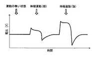
図9は、伸縮信号の波形の一例を示す波形図である。図9に示すように、伸縮信号は、生体の動きに応じた信号であり、例えば、振戦信号よりも低周波数で略DC成分の信号である。伸縮信号の振幅は、生体の負荷状態に応じて変化する。具体的には、生体が安静状態であり、動いていなければ、図9(左側の波形)に示すように、伸縮信号の振幅は、略基準電圧である。また、腱や筋が伸縮する小さな動きが生体に生じた場合(低負荷運動)、図9(中央の波形)に示すように、伸縮信号の振幅は、所定のレベル(強度)になる。また、生体に腱や筋が伸縮する大きな動きが生体に生じた場合(高負荷運動)、図9(右側の波形)に示すように、伸縮信号の振幅は、さらに大きくなる。 FIG. 9 is a waveform diagram showing an example of the waveform of the expansion/contraction signal. As shown in FIG. 9, the expansion/contraction signal is a signal according to the movement of the living body, and is, for example, a signal of a substantially DC component at a lower frequency than the tremor signal. The amplitude of the expansion/contraction signal changes according to the load state of the living body. Specifically, if the living body is in a resting state and is not moving, the amplitude of the expansion/contraction signal is approximately the reference voltage as shown in FIG. 9 (the waveform on the left side). In addition, when a small movement in which a tendon or a muscle expands or contracts occurs in a living body (low-load exercise), the amplitude of the expansion/contraction signal becomes a predetermined level (strength) as shown in FIG. 9 (center waveform). Further, when a large movement occurs in the living body in which the tendons and muscles expand and contract (high load exercise), the amplitude of the expansion and contraction signal is further increased as shown in FIG. 9 (waveform on the right side).
このように、信号処理部22を用いることで、センサモジュール20は、圧電センサ21で発生する電圧から伸縮信号と振戦信号とを個別に取得し、出力できる。この際、センサモジュール20は、観測対象の腱や筋の負荷状態に応じた振幅の伸縮信号と振戦信号とを抽出して、出力できる。 As described above, by using the
(検出モジュール30の構成および処理)
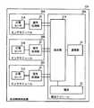
図10は、検出モジュールの構成を示すブロック図である。図10に示すように、検出モジュール30は、振戦信号検出部311、伸縮信号検出部312、および、状態解析部313を備える。なお、検出モジュール30は、少なくとも振戦信号検出部311と伸縮信号検出部312とを備えていればよい。検出モジュール30は、MCU等によって実現可能である。(Configuration and Processing of Detection Module 30)
FIG. 10 is a block diagram showing the configuration of the detection module. As shown in FIG. 10, the
振戦信号検出部311には、信号処理部22から、振戦信号が入力される。振戦信号検出部311は、振戦信号のレベル(振幅)を検出し、状態解析部313に出力する。伸縮信号検出部312には、信号処理部22から、伸縮信号が入力される。伸縮信号検出部312は、伸縮信号のレベル(振幅)を検出し、状態解析部313に出力する。 The tremor signal is input to the tremor
状態解析部313は、振戦信号のレベルと伸縮信号のレベルとを用いて、観測対象の腱または筋の活動状態を解析する。図11は、活動状態の解析テーブルの一例を示す図である。 The
(等尺性収縮が発生し、等張性収縮が発生していない場合)
図11に示すように、等張性収縮が発生しておらず、等尺性収縮が発生している場合、振戦信号の振幅は大きくなり、伸縮信号の振幅は変化しない。したがって、状態解析部313は、振戦信号の規定の単位時間における平均振幅が閾値THa以上であり、伸縮信号の規定の単位時間における平均振幅の変化量が閾値THb未満(典型的には基準値から実質的に動かない状態等)であると、等尺性収縮が発生しており等張性収縮が発生していない状態であると判定する。なお、振戦信号の規定の単位時間における平均振幅が閾値THa以上の状態は、図8における負荷がある状態(図8中央の波形、図8右側の波形に対応)である。また、伸縮信号の規定の単位時間における平均振幅の変化量が閾値THb未満であるか、または基準値から実施的に変化しない状態は、図9における運動の無い状態(図9左側の波形に対応)である。(When isometric contraction occurs but isotonic contraction does not occur)
As shown in FIG. 11, when isotonic contraction has not occurred and isometric contraction has occurred, the amplitude of the tremor signal increases and the amplitude of the expansion/contraction signal does not change. Therefore, the
(等張性収縮が発生し、等尺性収縮が発生していない場合)
図11に示すように、等尺性収縮が発生しておらず、等張性収縮が発生している場合、振戦信号の振幅は大きくなり、伸縮信号の振幅は変化する。したがって、状態解析部313は、振戦信号の規定の単位時間における平均振幅が閾値THa以上であり、伸縮信号の規定の単位時間における平均振幅の変化量が閾値THb以上であると、等尺性収縮が発生しておらず、等張性収縮が発生している状態であると判定する。なお、伸縮信号の振幅に変化がある状態は、図9における運動のある状態(図9中央の波形および図9の右側の波形に対応)である。(When isotonic contraction occurs but isometric contraction does not occur)
As shown in FIG. 11, when isometric contraction does not occur and isotonic contraction occurs, the amplitude of the tremor signal increases and the amplitude of the contraction signal changes. Therefore, the
(他動可動が発生している場合)
他動可動とは、観測対象の腱または筋を備える生体が、意識せずに、外部から力をかけられて動く状態を意味する。例えば、リハビリ時のセラピストや介護装具等により、足が外力によって動かされている状態等である。(When passive movement occurs)
Passive movement refers to a state in which a living body including a tendon or a muscle to be observed moves without being conscious of by being externally applied with a force. For example, it is a state in which the foot is moved by an external force by a therapist at the time of rehabilitation, nursing equipment, or the like.
図11に示すように、他動可動が発生している場合、振戦信号の振幅は小さくなり、伸縮信号の振幅は変化する。したがって、状態解析部313は、振戦信号の振幅が閾値THa未満であり、伸縮信号の振幅の変化量が閾値THb以上であると、他動可動が発生している状態であると判定する。なお、振戦信号の振幅が閾値THa未満の状態は、図8における負荷がない状態(図8左側の波形に対応)である。 As shown in FIG. 11, when the passive movement is generated, the amplitude of the tremor signal becomes small and the amplitude of the expansion/contraction signal changes. Therefore, if the amplitude of the tremor signal is less than the threshold THa and the amount of change in the amplitude of the expansion/contraction signal is not less than the threshold THb, the
(安静状態)
安静状態とは、運動を行っておらず、姿勢維持の負荷をかけず、他動可動もない状態を意味する。(Rest state)
The resting state means a state in which no exercise is performed, no load is applied to maintain the posture, and no passive movement is performed.
図11に示すように、安静状態の場合、振戦信号の振幅は小さくなり、伸縮信号の振幅は変化しない。したがって、状態解析部313は、振戦信号の振幅が閾値THa未満であり、伸縮信号の振幅が閾値THb未満であると、安静状態であると判定する。 As shown in FIG. 11, in the resting state, the amplitude of the tremor signal becomes small and the amplitude of the expansion/contraction signal does not change. Therefore, when the amplitude of the tremor signal is less than the threshold value THa and the amplitude of the expansion/contraction signal is less than the threshold value THb, the
このように、センサモジュール20からの信号を用いることによって、検出モジュール30は、等尺性収縮のみが発生している状態、等張性収縮が発生している状態、他動可動が発生している状態、および、安静状態を、個別に検出できる。 As described above, by using the signal from the
なお、上述の説明では、筋活動観測装置10の処理を、複数の機能部で実現する態様を示した。しかしながら、次に示すような筋活動観測方法をプログラム化して記憶部に記憶しておき、演算装置によって当該プログラムを読み出して実行する態様を用いてもよい。 In the above description, the process of the muscle
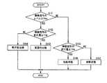
図12は、筋活動観測方法のフローを示す図である。図13は、状態解析のフローを示す図である。なお、各処理の具体的な内容は、上述しており、説明は省略する。 FIG. 12 is a diagram showing a flow of a muscle activity observation method. FIG. 13 is a diagram showing a flow of state analysis. The specific content of each process has been described above, and description thereof will be omitted.
演算装置は、センサの出力信号を取得する(S11)。演算装置は、センサの出力信号から、振戦信号を抽出して増幅する(S12)。演算装置は、センサの出力信号から、伸縮信号を抽出して増幅する(S13)。なお、ステップS12の処理とステップS13の処理の順はこれに限らず、逆でもよく、同時並行処理であってもよい。 The arithmetic unit acquires the output signal of the sensor (S11). The arithmetic unit extracts and amplifies the tremor signal from the output signal of the sensor (S12). The arithmetic unit extracts the expansion/contraction signal from the output signal of the sensor and amplifies it (S13). Note that the order of the processing of step S12 and the processing of step S13 is not limited to this, and may be reversed or simultaneous parallel processing.
演算装置は、振戦信号のレベルを検出する(S14)。演算装置は、伸縮信号の変化量を検出する(S15)。なお、ステップS14の処理とステップS15の処理の順はこれに限らず、逆でもよく、同時並行処理であってもよい。 The arithmetic unit detects the level of the tremor signal (S14). The arithmetic unit detects the amount of change in the expansion/contraction signal (S15). Note that the order of the processing of step S14 and the processing of step S15 is not limited to this, and may be reversed or simultaneous parallel processing.
演算装置は、振戦信号のレベルと伸縮信号の変化量とを用いて、観測対象の腱または筋の状態を解析する(S13)。具体的には、演算装置は、振戦信号の平均レベルが閾値THa以上であり(S161:YES)、伸縮信号の平均変化量が閾値THb以上であれば(S162:YES)、等張性収縮が生じていると判定する(S163)。演算装置は、振戦信号の平均レベルが閾値THa以上であり(S161:YES)、伸縮信号の平均変化量が閾値THb未満であれば(S162:NO)、等尺性収縮が生じていると判定する(S164)。演算装置は、振戦信号の平均レベルが閾値THa未満であり(S161:NO)、伸縮信号の平均変化量が閾値THb以上であれば(S165:YES)、他動可動であると判定する(S166)。演算装置は、振戦信号の平均レベルが閾値THa未満であり(S161:NO)、伸縮信号の平均変化量が閾値THb未満であれば(S165:NO)、安静状態であると判定する(S167)。なお、上記の平均レベル、平均変化量の「平均」とは、規定の単位時間における平均のことである。 The arithmetic device analyzes the state of the tendon or muscle to be observed using the level of the tremor signal and the amount of change in the expansion/contraction signal (S13). Specifically, if the average level of the tremor signal is equal to or higher than the threshold THa (S161: YES) and the average change amount of the expansion/contraction signal is equal to or higher than the threshold THb (S162: YES), the arithmetic device contracts isotonic. Is determined to have occurred (S163). If the average level of the tremor signal is equal to or higher than the threshold THa (S161: YES) and the average change amount of the expansion/contraction signal is less than the threshold THb (S162: NO), the arithmetic device determines that isometric contraction has occurred. The determination is made (S164). If the average level of the tremor signal is less than the threshold value THa (S161: NO) and the average change amount of the expansion/contraction signal is equal to or greater than the threshold value THb (S165: YES), the arithmetic device determines that it is passively movable ( S166). If the average level of the tremor signal is less than the threshold THa (S161: NO) and the average change amount of the expansion/contraction signal is less than the threshold THb (S165: NO), the arithmetic unit determines that the user is in a resting state (S167). ). The “average” of the average level and the average change amount described above is an average in a prescribed unit time.
なお、上述の説明では、振戦の周波数を約10Hzとしている。しかしながら、例えば、振戦の周波数は、0.5Hzから100Hz、より好ましくは、3Hzから25Hzにするとよい。これは、不随意運動に伴う機械的運動には生理的振戦に加え、病理的振戦、筋音図、マイクロバイブレーション、心弾動図などがあるからである。これらの信号との区別を行うためにも、振戦の周波数を0.5Hzから100Hzとして計測するシステムとすることが望ましい。 In the above description, the tremor frequency is about 10 Hz. However, for example, the tremor frequency may be 0.5 Hz to 100 Hz, and more preferably 3 Hz to 25 Hz. This is because the mechanical movements associated with involuntary movements include pathological tremors, myocardiograms, microvibrations, and ballistocardiograms in addition to physiological tremors. In order to distinguish from these signals, it is desirable to use a system that measures the tremor frequency from 0.5 Hz to 100 Hz.
また、生理的振戦は、8Hzから12Hzが中心周波数となるが、部位に依存する周波数も存在する。例えば、上肢は3Hz、手の指は25Hzである。したがって、振戦の周波数を3Hzから25Hzとして計測するシステムとすることがより望ましい。 Further, the physiological tremor has a center frequency of 8 Hz to 12 Hz, but there is a frequency depending on the part. For example, the upper limb has a frequency of 3 Hz and the finger of the hand has a frequency of 25 Hz. Therefore, it is more desirable to use a system that measures the tremor frequency from 3 Hz to 25 Hz.
また、上述の説明では、側面視して略L字状の生体支持体40を例に示したが、図14に示すような形状であってもよい。図14は、筋活動観測装置の足への装着の状態を示す側面図である。 Further, in the above description, the
図14に示すように、生体支持体40Aは、円筒形である。生体支持体40Aは、上述の生体支持体40における第1部分41に類似する形状である。生体支持体40Aは、足首91を覆うように配置される。 As shown in FIG. 14, the
また、図14に示す構成では、センサモジュール20と検出モジュール30とは、円筒形からなる生体支持体40Aの円筒形の周方向に沿って並んで配置されている。そして、センサモジュール20と検出モジュール30とは、この周方向に延びる配線によって接続されている。 Further, in the configuration shown in FIG. 14, the
このように、図14に記載の構成にすることで、例えば、筋活動観測装置10の構成を簡素化でき、装着が容易になる。 As described above, with the configuration shown in FIG. 14, for example, the configuration of the muscle
また、上述の説明では、センサモジュール20を足に装着しているが、次に示すように、体の他の部位に装着することも可能である。図15(A)、図15(B)は、腕(上腕)および大腿に装着した態様を示し、図15(C)、図15(D)は、前腕に装着した態様を示す図である。図16(A)、図16(B)は、胸、腹、背中、腰に装着した態様を示す図である。 Further, although the
図15(A)、図15(B)に示すように、上腕991に装着する場合、センサモジュール20における圧電センサ21の長さ方向を、上腕991の延びる方向に直交させるとよい。また、図15(A)、図15(B)に示すように、大腿992に装着する場合、センサモジュール20における圧電センサ21の長さ方向を、大腿992の延びる方向に直交させるとよい。また、図15(C)、図15(D)に示すように、前腕993に装着する場合、センサモジュール20における圧電センサ21の長さ方向を、前腕993の延びる方向に直交させるとよい。なお、図15(A)、図15(B)では、センサモジュール20および検出モジュール30の組は、装着対象に対して、2個装着されているが、1個であってもよい。 As shown in FIGS. 15A and 15B, when mounted on the
また、図16(A)、図16(B)に示すように、胸994および背中996に装着する場合、センサモジュール20における圧電センサ21の長さ方向を、胸994および背中996の幅方向に平行にするとよい。また、図16(A)、図16(B)に示すように、腹995および腰997に装着する場合、センサモジュール20における圧電センサ21の長さ方向を、腹995および腰997の幅方向に平行にするとよい。 Further, as shown in FIGS. 16(A) and 16(B), when mounted on the
また、図15(A)、図15(B)、図15(C)、図15(D)、図16(A)、図16(B)の装着態様に対して、例えば、体の前側と後ろ側のセンサモジュール20を1個の生体支持体40Aに配置し、これらに対して、同じく生体支持体40Aに配置された共通の1個の検出モジュール30を接続してもよい。 Further, with respect to the wearing modes of FIGS. 15A, 15B, 15C, 15D, 16A, and 16B, for example, the front side of the body The
なお、足を検出対象とすることによって、靴下自体で振戦信号等を検出したり、靴下やストッキングの上から振戦信号等を検出したりできる。また、筋負荷と足関節の動きを同時に検出できる。脚または足は、装着している感覚を忘れやすいように、人間の意識から遠い装着位置であり、腕、腰、胸部等と比較して、センサモジュール20の装着に対する違和感を少なくできる。下腿最小囲付近への装着であれば、靴の有無、靴下の有無にも影響されない。前脛骨筋、ヒラメ筋、腓腹筋と、日常生活動作、姿勢維持、歩行時に重要な筋肉を検出、観測できる。両脚に装着すれば、歩行、ジョギング、下肢トレーニング、下肢リハビリ等の分析、定量化に利用できる。 By using the foot as a detection target, it is possible to detect a tremor signal or the like in the socks themselves, or to detect a tremor signal or the like from the socks or stockings. Further, the muscle load and the movement of the ankle joint can be detected at the same time. The legs or feet are at a mounting position far from human consciousness so that the user can easily forget the feeling of wearing, and it is possible to reduce discomfort when mounting the
(第2の実施形態)
本発明の第2の実施形態に係る筋活動観測装置について、図を参照して説明する。図17は、第2の実施形態に係る筋活動観測装置の構成を示すブロック図である。図18(A)は、筋活動観測装置の足への装着の状態を示す側面図であり、図18(B)は、筋活動観測装置の足への装着状態を示す平面図である。(Second embodiment)
A muscle activity observation apparatus according to the second embodiment of the present invention will be described with reference to the drawings. FIG. 17 is a block diagram showing the configuration of the muscle activity observation device according to the second embodiment. FIG. 18(A) is a side view showing a state in which the muscle activity observation device is attached to the foot, and FIG. 18(B) is a plan view showing a state in which the muscle activity observation device is attached to the foot.
図17に示すように、第2の実施形態に係る筋活動観測装置10Aは、第1の実施形態に筋活動観測装置10に対して、センサモジュール20A、センサモジュール20B、および、センサモジュール20Cを備える点、検出部31Aの処理において異なる。筋活動観測装置10Aの他の構成は、筋活動観測装置10と同様であり、同様の箇所の説明は省略する。 As shown in FIG. 17, the muscle activity observation apparatus 10A according to the second embodiment includes a
センサモジュール20A、センサモジュール20B、および、センサモジュール20Cは、第1の実施形態に係るセンサモジュール20と同様の構成および処理を実行する。図18(A)、図18(B)に示すように、センサモジュール20Aの圧電センサ21Aは、アキレス腱901に重なるように、下腿最小囲90に装着されている。センサモジュール20Bの圧電センサ21Bは、前脛骨筋腱902に重なるように装着されている。センサモジュール20Cの圧電センサ21Cは、長腓骨筋腱903に重なるように装着されている。すなわち、筋活動観測装置10Aは、腱または筋の活動の検出箇所を複数としている。 The
センサモジュール20A、センサモジュール20B、および、センサモジュール20Cは、それぞれで抽出した振戦信号および伸縮信号を、検出モジュール30Aの検出部31Aに出力する。 The
検出部31Aは、上述の検出部31と同様に、等尺性収縮、等張性収縮、他動可動、または、安静状態を検出するとともに、足の動作状態を解析する。図19は、部位と動作と対象の腱・筋肉との関係の一例を示す表である。 Similar to the above-mentioned detecting
検出部31Aは、センサモジュール20Aの振戦信号と伸縮信号とから、等張性収縮を検出すると、アキレス腱901の伸縮を検出する。検出部31Aは、センサモジュール20Bの振戦信号と伸縮信号とから、等張性収縮を検出すると、前脛骨筋腱902の伸縮を検出する。検出部31Aは、センサモジュール20Cの振戦信号と伸縮信号とから、等張性収縮を検出すると、長腓骨筋腱903の伸縮を検出する。 When detecting the isotonic contraction from the tremor signal and the expansion/contraction signal of the
検出部31Aは、アキレス腱901の伸縮、前脛骨筋腱902の伸縮、および、長腓骨筋腱903の伸縮を用いて、足(下腿)の動作状態を検出する。例えば、図19に示すように、検出部31Aは、アキレス腱901の伸縮(ヒラメ筋、腓腹筋等の伸縮)を検出すれば、足の屈曲(底屈)または内がえしがあると判定する。また、図19に示すように、検出部31Aは、前脛骨筋腱902の伸縮(前脛骨筋の伸縮)を検出すれば、足の伸展(背屈)があると判定する。また、図19に示すように、検出部31Aは、長腓骨筋腱903の伸縮を検出すれば、足の外がえしがあると判定する。このように、筋活動観測装置10Aは、足の各種の動作状態を判定できる。 The detection unit 31A detects the motion state of the foot (lower leg) using the expansion and contraction of the
なお、足以外についても、上述の図15(A)、図15(B)、図15(C)、図15(D)、図16(A)、図16(B)に示すような装着態様を実現することで、図19に示すように、他の部位についても、動作状態を検出する。 It should be noted that, as for the parts other than the foot, the wearing modes as shown in the above-described FIG. 15(A), FIG. 15(B), FIG. 15(C), FIG. 15(D), FIG. 16(A), and FIG. 16(B). By realizing the above, as shown in FIG. 19, the operating states of other parts are also detected.
例えば、大腿四頭筋の伸縮を検出すれば、膝(大腿)の屈曲を判定できる。ハムストリングスの伸縮を検出すれば、膝(大腿)の伸展を判定できる。手の掌屈筋群(深指屈筋/浅指屈筋/長母子屈筋等)の伸縮を検出すれば、手、指の屈曲(掌屈)を判定できる。手の背屈筋群(総指伸筋等)の伸縮を検出すれば、手、指の伸展(背屈)を判定できる。上腕二頭筋の伸縮を検出すれば、肘(上腕)の屈曲を判定できる。上腕三頭筋の伸縮を検出すれば、肘(上腕)の伸展を判定できる。腹直筋の伸縮を検出すれば、腹・腰の屈曲(脊柱の前屈)を判定できる。固有背筋群(脊柱起立筋等)の伸縮を検出すれば、腹・腰の伸展(脊柱の後屈)を判定できる。大胸筋の伸縮を検出すれば、胸の屈曲(収縮)を判定できる。広背筋の伸縮を検出すれば、胸の伸展を判定できる。 For example, if flexion of the quadriceps femoris is detected, flexion of the knee (thigh) can be determined. The extension of the knee (thigh) can be determined by detecting the expansion and contraction of the hamstrings. The flexion of the hand and fingers (palm flexion) can be determined by detecting the expansion and contraction of the palm flexor muscles (deep digital flexor/shallow digital flexor/long maternal flexor, etc.). By detecting the expansion and contraction of the dorsiflexor group of the hand (extensor digitum extensus, etc.), the extension of the hand and fingers (dorsiflexion) can be determined. The flexion of the elbow (upper arm) can be determined by detecting the expansion and contraction of the biceps. The extension of the elbow (upper arm) can be determined by detecting the expansion and contraction of the triceps. The flexion of the abdomen/waist (anterior flexion of the spine) can be determined by detecting the expansion and contraction of the rectus abdominis muscle. Extending the abdomen/waist (backward flexion of the spinal column) can be determined by detecting the expansion and contraction of the proper back muscle group (the erector spinae muscles). The flexion (contraction) of the chest can be determined by detecting the expansion and contraction of the pectoralis major muscle. Chest extension can be determined by detecting the expansion and contraction of the latissimus dorsi.
(第3の実施形態)
本発明の第3の実施形態に係る筋活動観測装置について、図を参照して説明する。図20(A)は、第3の実施形態に係る筋活動観測装置の構成を示すブロック図である。図20(B)は、信号処理部の構成を示すブロック図である。(Third Embodiment)
A muscle activity observation apparatus according to the third embodiment of the present invention will be described with reference to the drawings. FIG. 20A is a block diagram showing the configuration of the muscle activity observation apparatus according to the third embodiment. FIG. 20B is a block diagram showing the configuration of the signal processing unit.
図20(A)に示すように、第3の実施形態に係る筋活動観測装置10Bは、第1の実施形態に係る筋活動観測装置10に対して、信号処理部22B、センサモジュール20Bを備える点で異なる。筋活動観測装置10Bの他の構成は、筋活動観測装置10と同様であり、同様の箇所の説明は省略する。 As shown in FIG. 20(A), the muscle activity observation device 10B according to the third embodiment includes a signal processing unit 22B and a
信号処理部22Bは、信号処理部22に対して、送信制御部227をさらに備える。送信制御部227は、フィルタ回路225およびフィルタ回路226に接続している。送信制御部227は、振戦信号と伸縮信号とを時分割で、検出部31に送信する。 The signal processing unit 22B further includes a
このような構成とすることによって、センサモジュール20Bと検出モジュール30とを接続する通信ケーブルの構成を簡素化できる。 With such a configuration, the configuration of the communication cable that connects the
(第4の実施形態)
本発明の第4の実施形態に係る筋活動観測装置について、図を参照して説明する。図21は、第4の実施形態に係る筋活動観測装置におけるセンサモジュールの構成を示すブロック図である。(Fourth Embodiment)
A muscle activity observation apparatus according to the fourth embodiment of the present invention will be described with reference to the drawings. FIG. 21 is a block diagram showing the configuration of the sensor module in the muscle activity observation device according to the fourth embodiment.
図21に示すように、センサモジュール20Cは、センサモジュール20に対して、圧電センサ21を備えず、振戦観測用センサ21trおよび伸縮観測用センサ21tmを備える点で異なる。センサモジュール20Cの他の構成は、センサモジュール20と同様であり、同様の箇所の説明は省略する。 As shown in FIG. 21, the sensor module 20C differs from the
振戦観測用センサ21trは、上述の振戦信号を検出するセンサである。例えば、振戦観測用センサ21trは、加速度センサ、マイク等によって実現される。なお、振戦観測用センサ21trは、圧電センサ21によっても実現可能である。また、振戦観測用センサ21trは、10Hz程度の信号を検出できるものであれば、他のセンサであってもよい。 The tremor observation sensor 21tr is a sensor that detects the above-described tremor signal. For example, the tremor observation sensor 21tr is realized by an acceleration sensor, a microphone, or the like. The tremor observation sensor 21tr can also be realized by the
振戦観測用センサ21trは、振戦に基づく電気的な変化を、信号処理部22Cの振戦信号抽出回路221に出力する。 The tremor observation sensor 21tr outputs an electrical change based on tremor to the tremor
伸縮観測用センサ21tmは、上述の伸縮信号を検出するセンサである。例えば、伸縮観測用センサ21tmは、圧電センサ21によって実現される。なお、伸縮観測用センサ21tmは、観測対象の腱や筋の伸縮に応じて状態が変化し、この状態変化に応じた電気信号が得られるものであれば、他のセンサであってもよい。他のセンサとしては、例えば、感圧膜を用いた感圧センサ、ダイヤフラム変形による歪み変化、静電容量変化を検出する圧力センサ・荷重センサ等を用いてもよい。 The stretch observation sensor 21tm is a sensor that detects the stretch signal. For example, the stretch observation sensor 21tm is realized by the
伸縮観測用センサ21tmは、腱または筋の伸縮に基づく電気的な変化を、信号処理部22Cの伸縮信号抽出回路222に出力する。 The stretch observation sensor 21tm outputs an electrical change based on the stretch of the tendon or muscle to the stretch
このセンサモジュール20Cのように、振戦信号を検出するセンサと、伸縮信号を検出するセンサとを別にしてもよい。その場合、振戦信号を検出するセンサの補助板と、伸縮信号を検出するセンサの補助板とは、それぞれの信号の検出に適する材料、特性のものにするとよい。 Like this sensor module 20C, a sensor that detects a tremor signal and a sensor that detects a stretch signal may be separated. In that case, the auxiliary plate of the sensor for detecting the tremor signal and the auxiliary plate of the sensor for detecting the expansion/contraction signal may be made of materials and characteristics suitable for detecting the respective signals.
(第5の実施形態)
本発明の第5の実施形態に係る筋活動観測装置について、図を参照して説明する。図22は、第5の実施形態に係る筋活動観測装置におけるセンサモジュールの構成を示すブロック図である。(Fifth Embodiment)
A muscle activity observation apparatus according to the fifth embodiment of the present invention will be described with reference to the drawings. FIG. 22 is a block diagram showing the configuration of the sensor module in the muscle activity observation device according to the fifth embodiment.
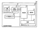
図22に示すように、第5の実施形態に係る筋活動観測装置10Dは、第1の実施形態に係る筋活動観測装置10に対して、ノイズ観測センサ50を追加した点、検出部31Dの処理において異なる。筋活動観測装置10Dの他の構成は、筋活動観測装置10と同様であり、同様の箇所の説明は省略する。 As shown in FIG. 22, the muscle activity observation apparatus 10D according to the fifth embodiment is different from the muscle
ノイズ観測センサ50は、例えば、加速度センサであり、観測対象の生体の部位の動作を検出して、動作ノイズを生成する。ノイズ観測センサ50は、動作ノイズを検出部31Dに出力する。 The
検出部31Dは、動作ノイズを用いて、振戦信号および伸縮信号に含まれるノイズを抑圧する。 The detection unit 31D suppresses noise included in the tremor signal and the expansion/contraction signal by using the operation noise.
この構成によって、検出部31Dは、腱または筋の動作状態を、より高精度に解析できる。 With this configuration, the detection unit 31D can analyze the operating state of the tendon or the muscle with higher accuracy.
なお、各実施形態の構成において、振戦信号の検出を、筋活動観測装置の起動に用いることも可能である。例えば、筋活動観測装置は、スリープモードとして、振戦信号のレベルのみを観測する。そして、筋活動観測装置は、振戦信号のレベルが閾値THa以上になることを検出し、スリープモードから起動して、振戦信号および伸縮信号を観測する。これにより、筋活動観測装置は省電力化される。 In addition, in the configuration of each embodiment, the detection of the tremor signal can be used to activate the muscle activity observation device. For example, the muscle activity observation device observes only the level of the tremor signal in the sleep mode. Then, the muscle activity observation device detects that the level of the tremor signal becomes equal to or higher than the threshold value THa, activates from the sleep mode, and observes the tremor signal and the expansion/contraction signal. This saves power in the muscle activity observation device.
また、各実施形態では、圧電センサは、生体支持体40を用いて装着されている。しかしながら、圧電センサは、生体支持体40を用いずに、生体に直接装着されていてもよい。 Further, in each of the embodiments, the piezoelectric sensor is mounted using the
また、上述の説明では、圧電センサは、足首付近の特定の腱に重ねて配置されている。しかしながら、圧電センサの配置位置は、これに限らず、観測対象の腱または筋に重なっていればよく、さらには、腱または筋に重なっていなくても、腱または筋の動きの影響を受ける位置であればよい。 Further, in the above description, the piezoelectric sensor is arranged so as to overlap a specific tendon near the ankle. However, the arrangement position of the piezoelectric sensor is not limited to this, as long as it overlaps with the tendon or muscle to be observed, and even if it does not overlap with the tendon or muscle, the position affected by the movement of the tendon or muscle. If
また、上述の説明では、圧電センサの圧電体の材料として、ポリ乳酸、窒化アルミニウムを用いる態様を示した。しかしながら、圧電体の材料は、無機圧電材料として、水晶、圧電セラミックスであるPZT及び(Pb,La)(Zr,Ti)OXぺロブスカイト化合物(PZLT)や、圧電単結晶であるニオブ酸ジルコン酸鉛‐チタン酸鉛固溶体(PZN‐PT)、マグネシウムニオブ酸鉛‐チタン酸鉛固溶体(PMN‐PT)、ニオブ酸リチウム(LiNbO3)、タンタル酸リチウム(LiTaO3)、ニオブ酸カリウム(KNbO3)、酸化亜鉛(ZnO)等の薄膜を用いることが可能である。また、有機圧電材料としては、ポリフッ化ビニリデン、ポリフッ化ビニリデン系共重合体、ポリシアン化ビニリデン、シアン化ビニリデン系共重合体、ナイロン9やナイロン11等の奇数ナイロン、芳香族ナイロン、脂環族ナイロン、ポリヒドロキシブチレート等のポリヒドロキシカルボン酸、セルロース系誘導体及びポリウレア等が挙げられる。Further, in the above description, the mode in which polylactic acid or aluminum nitride is used as the material of the piezoelectric body of the piezoelectric sensor is shown. However, the material of the piezoelectric body is quartz, piezoelectric ceramics such as PZT and (Pb,La)(Zr,Ti)OX perovskite compound (PZLT) as an inorganic piezoelectric material, or piezoelectric single crystal lead zirconate niobate. - lead titanate solid solution (PZN-PT), lead magnesium niobate - lead titanate solid solution (PMN-PT), lithium niobate (LiNbO3), lithium tantalate (LiTaO3), potassium niobate (KNbO3), It is possible to use a thin film of zinc oxide (ZnO) or the like. Further, as the organic piezoelectric material, polyvinylidene fluoride, polyvinylidene fluoride-based copolymer, polyvinylidene cyanide, vinylidene cyanide-based copolymer, odd-numbered nylon such as nylon 9 and
また、上述の説明では、生体支持体40は、筒状であったが、帯状であってもよく、靴下等の衣類であってもよい。 In addition, in the above description, the
また、上述の各実施形態に示した筋活動観測装置の構成は、適宜組合せが可能であり、それぞれの組合せに応じた作用効果が得られる。 Further, the configurations of the muscle activity observation apparatuses shown in the above-described respective embodiments can be appropriately combined, and operational effects corresponding to each combination can be obtained.
また、上述の説明では、振戦と伸縮を用いて、観測対象の腱または筋の状態を解析している。しかしながら、振戦だけで解析を行うことも可能である。振戦だけを用いた場合、筋収縮(曲げ)の分析を必要としない定量化では、装置の構成を簡素化できる。腱のある位置だけでなく、筋腹等の設置場所の自由度が増す。上述のように、圧電フィルムに代えて、加速度センサまたはマイク(高感度マイク)等を用いることができる。 Further, in the above description, the condition of the observation target tendon or muscle is analyzed using tremor and expansion/contraction. However, it is also possible to perform the analysis only by tremor. When using only tremor, quantification that does not require analysis of muscle contraction (bending) can simplify the configuration of the device. Not only the location of the tendons but also the flexibility of the installation location such as the muscle belly increases. As described above, an acceleration sensor, a microphone (high-sensitivity microphone), or the like can be used instead of the piezoelectric film.
(筋活動観測システムの構成例)
上述の各実施形態に示した筋活動観測装置は、例えば、図23、図24に示すような筋活動観測システムに採用できる。なお、以下では、第1の実施形態に係る筋活動観測装置10を用いる態様を示すが、他の実施形態の筋活動観測装置も用いることができる。(Example of muscle activity observation system configuration)
The muscle activity observation device shown in each of the above-described embodiments can be adopted in, for example, a muscle activity observation system as shown in FIGS. 23 and 24. In addition, below, although the aspect which uses the muscle
図23は、筋活動観測システムの第1態様例を示すブロック図である。図23に示すように、筋活動観測システム1は、筋活動観測装置10とサーバ60とを備える。 FIG. 23 is a block diagram showing a first aspect example of the muscle activity observation system. As shown in FIG. 23, the muscle
サーバ60は、例えば、サーバ制御部61、通信部62、および、データベース610を備える。サーバ制御部61は、サーバ60の全体制御を行う。また、サーバ制御部61は、腱または筋の活動の解析結果、足の動作状態等のデータベース610への登録、読み出し等を実行する。 The
通信部62は、筋活動観測装置10の通信部32と、データ通信を行う。通信部62は、筋活動観測装置10からの腱または筋の活動の解析結果、足の動作状態を受信して、サーバ制御部61に出力する。通信部62と通信部32との通信は、無線通信であっても、有線通信であってもよい。 The communication unit 62 performs data communication with the
このような構成によって、筋活動観測装置10で得られた腱または筋の活動の解析結果、足の動作状態等を、データベース化して記憶しておき、ユーザは、必要に応じてこれらを利用できる。 With such a configuration, the analysis result of the activity of the tendon or muscle obtained by the muscle
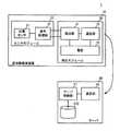
図24は、筋活動観測システムの第2態様例を示すブロック図である。図24に示すように、筋活動観測システム1Aは、筋活動観測装置10と情報端末70とを備える。 FIG. 24 is a block diagram showing a second mode example of the muscle activity observation system. As shown in FIG. 24, the muscle activity observation system 1A includes a muscle
情報端末70は、例えば、演算部71、通信部72、記憶部73、表示部74、および、操作部75を備える。 The information terminal 70 includes, for example, a calculation unit 71, a communication unit 72, a storage unit 73, a display unit 74, and an operation unit 75.
演算部71は、情報端末70の全体制御を行う。通信部72は、筋活動観測装置10の通信部32と、データ通信を行う。通信部72と通信部32との通信は、無線通信であっても、有線通信であってもよい。通信部72は、筋活動観測装置10からの腱または筋の活動の解析結果、足の動作状態を受信して、演算部71に出力する。記憶部73には、アプリケーションプログラム730が記憶されている。また、記憶部73には、通信部72を介して受信した腱または筋の活動の解析結果、足の動作状態が記憶されている。表示部74は、液晶ディスプレイ等から構成される。操作部75は、タッチパネル等から構成される。 The arithmetic unit 71 controls the entire information terminal 70. The communication unit 72 performs data communication with the
演算部71は、操作部75からの操作入力等に応じて、アプリケーションプログラム730を記憶部73から読み出して実行する。アプリケーションプログラム730は、例えば、腱または筋の活動の解析結果、足の動作状態等を可視化するプログラムである。 The calculation unit 71 reads the application program 730 from the storage unit 73 and executes it according to an operation input from the operation unit 75. The application program 730 is, for example, a program that visualizes an analysis result of tendon or muscle activity, a foot motion state, and the like.
演算部71は、アプリケーションプログラム730を実行する。この際、演算部71は、通信部72で受信した、または、記憶部73に記憶されている腱または筋の活動の解析結果、足の動作状態を用いて、アプリケーションプログラム730を実行する。演算部71は、アプリケーションプログラム730の実行結果を、表示部74に表示させる。 The calculation unit 71 executes the application program 730. At this time, the calculation unit 71 executes the application program 730 using the analysis result of the activity of the tendon or muscle received by the communication unit 72 or stored in the storage unit 73 and the operating state of the foot. The calculation unit 71 causes the display unit 74 to display the execution result of the application program 730.
このような構成によって、筋活動観測装置10で腱または筋の活動の解析結果、足の動作状態等を観測しながら、ユーザは、この観測結果を、視覚的に容易に確認できる。 With such a configuration, the user can easily visually confirm the observation result while observing the analysis result of the activity of the tendon or muscle, the operating state of the foot, etc. with the muscle
上述の筋活動観測システムの各構成は、適宜組合せが可能であり、それぞれの組合せに応じた作用効果が得られる。 The configurations of the muscle activity observation system described above can be combined as appropriate, and operational effects corresponding to each combination can be obtained.
1、1A:筋活動観測システム
10、10A、10B、10D:筋活動観測装置
20、20A、20B、20C:センサモジュール
21、21A、21B、21C:圧電センサ
21tm、21tr:振戦観測用センサ
22、22B、22C:信号処理部
22M:信号処理回路モジュール
30、30A:検出モジュール
31、31A、31D:検出部
32:通信部
33:電源
40、40A:生体支持体
41:第1部分
42:第2部分
43:穴
50:ノイズ観測センサ
60:サーバ
61:サーバ制御部
62:通信部
70:情報端末
71:演算部
72:通信部
73:記憶部
74:表示部
75:操作部
121:振戦信号抽出回路
201:圧電体
202:検出用電極
203:接着層
204:補助板
220C:伝送ケーブル
220M:接続端子
221:振戦信号抽出回路
222:伸縮信号抽出回路
223、224:増幅回路
225、226:フィルタ回路
227:送信制御部
311:振戦信号検出部
312:伸縮信号検出部
313:状態解析部
610:データベース
730:アプリケーションプログラム
90:下腿最小囲
91:足首
92:足の甲
93:踵
94:足の裏
901:アキレス腱
902:前脛骨筋腱
903:長腓骨筋腱
991:上腕
992:大腿
993:前腕
994:胸
995:腹
996:背中
997:腰1, 1A: Muscle activity observation system 10, 10A, 10B, 10D: Muscle activity observation device 20, 20A, 20B, 20C: Sensor module 21, 21A, 21B, 21C: Piezoelectric sensor 21tm, 21tr: Tremor observing sensor 22 , 22B, 22C: signal processing unit 22M: signal processing circuit module 30, 30A: detection module 31, 31A, 31D: detection unit 32: communication unit 33: power supply 40, 40A: biological support 41: first portion 42: second Two parts 43: hole 50: noise observation sensor 60: server 61: server control unit 62: communication unit 70: information terminal 71: calculation unit 72: communication unit 73: storage unit 74: display unit 75: operation unit 121: tremor Signal extraction circuit 201: Piezoelectric body 202: Detection electrode 203: Adhesive layer 204: Auxiliary plate 220C: Transmission cable 220M: Connection terminal 221: Tremor signal extraction circuit 222: Expansion/contraction signal extraction circuits 223, 224: Amplifier circuits 225, 226 : Filter circuit 227: Transmission control unit 311: Tremor signal detection unit 312: Stretching signal detection unit 313: State analysis unit 610: Database 730: Application program 90: Lower leg minimum wall 91: Ankle 92: Instep 93: Heel 94 : Sole 901: Achilles tendon 902: tibialis anterior tendon 903: peroneus longus tendon 991: upper arm 992: thigh 993: forearm 994: chest 995: abdomen 996: back 997: waist
Claims (21)
Translated fromJapanese前記腱または前記筋の伸縮によって出力が変化する第2センサと、
前記第1センサの出力信号と前記第2センサの出力信号とを用いて、前記腱または前記筋の活動状態として、等張性収縮が発生している状態、等尺性収縮が発生している状態、他動可動が発生している状態、あるいは、安静状態である状態のいずれの状態であるかを検出する検出部と、
を備える、筋活動観測装置。A first sensor whose output changes due to vibration of the tendon or muscle;
A second sensor whose output changes according to expansion and contraction of the tendon or the muscle;
Using the output signal of the first sensor and the output signal of the second sensor,as the activity stateof the tendon or the muscle, isotonic contraction has occurred or isometric contraction has occurred. A state, a state in which passive movement is occurring, or a state in which the state is a resting state, and a detection unit,
A muscle activity observing device.
請求項1に記載の筋活動観測装置。The first sensor and the second sensor are formed by one piezoelectric sensor,
The muscle activity observation device according to claim 1.
請求項2に記載の筋活動観測装置。The piezoelectric sensor has a rectangular shape having a main surface, and has a sheet shape.
The muscle activity observation device according to claim 2.
前記主面に平行に配置され、前記圧電センサを構成する圧電体よりも硬い補助板を備える、
請求項3に記載の筋活動観測装置。The piezoelectric sensor is
An auxiliary plate that is arranged parallel to the main surface and is harder than a piezoelectric body that constitutes the piezoelectric sensor is provided.
The muscle activity observation device according to claim 3.
前記矩形の長さ方向が前記腱または前記筋の延びる方向に対して略直交するように、配置されている、
請求項3または請求項4に記載の筋活動観測装置。The piezoelectric sensor is
The length direction of the rectangle is arranged so as to be substantially orthogonal to the extending direction of the tendon or the muscle,
The muscle activity observation device according to claim 3 or 4.
前記検出部は、
前記複数の組の前記第1センサの出力と前記第2センサの出力とを用いて、前記腱または前記筋の活動状態を検出する、
請求項1乃至請求項5のいずれかに記載の筋活動観測装置。There are a plurality of sets of the first sensor and the second sensor,
The detection unit,
Detecting the activity state of the tendon or the muscle using the outputs of the first sensor and the second sensor of the plurality of sets,
The muscle activity observation device according to any one of claims 1 to 5.
前記腱または前記筋の活動状態から、前記腱または前記筋が備えられた生体の部位の動作を検出する、
請求項1乃至請求項6のいずれかに記載の筋活動観測装置。The detection unit,
From the activity state of the tendon or the muscle, detecting the movement of the part of the living body provided with the tendon or the muscle,
The muscle activity observation device according to any one of claims 1 to 6.
前記第1センサおよび前記第2センサは、前記生体支持体に装着されている、
請求項1乃至請求項7のいずれかに記載の筋活動観測装置。The tendon or the muscle is a tubular shape that matches the outer shape of the living body in which it is built-in, and includes a living body support body that deforms in accordance with the movement of the living body,
The first sensor and the second sensor are attached to the living body support,
The muscle activity observation device according to any one of claims 1 to 7.
足首を覆う筒状の第1部分と、
足の甲から足の裏を覆う筒状であり、前記第1部分に繋がる第2部分と、
踵を露出する穴と、
を備える、請求項8に記載の筋活動観測装置。The biological support is to be attached to the foot of the human body,
A tubular first part covering the ankle;
A second part connected to the first part, which has a tubular shape covering the instep to the sole of the foot,
A hole exposing the heel,
The muscle activity observation device according to claim 8, further comprising:
前記検出部は、
前記振戦信号と前記伸縮信号とを用いて、前記腱または前記筋の活動状態を検出する、
請求項1乃至請求項9のいずれかに記載の筋活動観測装置。A signal that extracts a tremor signal from the output of the first sensor, extracts a stretch signal from the output of the second sensor, amplifies the tremor signal and the stretch signal, and outputs the amplified signal to the detection unit. Equipped with a processing unit,
The detection unit,
Using the tremor signal and the stretch signal to detect the activity state of the tendon or the muscle,
The muscle activity observation device according to any one of claims 1 to 9.
前記振戦信号と前記伸縮信号とを時分割で出力する、
請求項10に記載の筋活動観測装置。The signal processing unit,
Outputting the tremor signal and the expansion/contraction signal in a time division manner,
The muscle activity observation device according to claim 10.
請求項1乃至請求項11のいずれかに記載の筋活動観測装置。A communication unit for communicating the detection result of the detection unit to the outside,
The muscle activity observation device according to any one of claims 1 to 11.
前記腱または前記筋の伸縮を検出して伸縮信号を生成し、
前記振戦信号と前記伸縮信号とを用いて、前記腱または前記筋の活動状態として、等張性収縮が発生している状態、等尺性収縮が発生している状態、他動可動が発生している状態、あるいは、安静状態である状態のいずれの状態であるかを検出する、
筋活動観測方法。Detects vibrations of tendons or muscles to generate tremor signals,
Generates a stretch signal by detecting the stretch of the tendon or the muscle,
Using the tremor signal and the expansion/contraction signal, as the active stateof the tendon or the muscle, a state whereisotonic contraction occurs, a state where isometric contraction occurs, and passive movement occurs. To detectwhether you arein a resting state or a resting state ,
Muscle activity observation method.
請求項13に記載の筋活動観測方法。The tremor signal and the expansion/contraction signal are detected by one sensor,
The muscle activity observation method according to claim 13.
請求項14に記載の筋活動観測方法。The one sensor is a piezoelectric sensor,
The muscle activity observation method according to claim 14.
請求項14または請求項15に記載の筋活動観測方法。The one sensor is arranged such that a direction having high detection sensitivity is substantially orthogonal to a direction in which the tendon or the muscle extends.
The muscle activity observation method according to claim 14 or 15.
前記複数の検出箇所の前記振戦信号と前記伸縮信号とを用いて、前記腱または前記筋の活動状態を検出する、
請求項13乃至請求項16のいずれかに記載の筋活動観測方法。The detection points of the tremor signal and the expansion/contraction signal are plural,
Using the tremor signal and the expansion and contraction signal of the plurality of detection points, to detect the activity state of the tendon or the muscle,
The muscle activity observation method according to any one of claims 13 to 16.
請求項13乃至請求項17のいずれかに記載の筋活動観測方法。From the activity state of the tendon or the muscle, detecting the movement of the part of the living body provided with the tendon or the muscle,
The muscle activity observation method according to any one of claims 13 to 17.
請求項13乃至請求項18のいずれかに記載の筋活動観測方法。Amplifying the tremor signal and the expansion/contraction signal to be used for the detection,
The muscle activity observation method according to any one of claims 13 to 18.
請求項13乃至請求項19のいずれかに記載の筋活動観測方法。Outputting the tremor signal and the expansion/contraction signal in a time division manner,
The muscle activity observation method according to any one of claims 13 to 19.
請求項13乃至請求項20のいずれかに記載の筋活動観測方法。Communicate the detection result of the tendon or muscle obtained from the tremor signal and the stretching signal to the outside,
The muscle activity observation method according to any one of claims 13 to 20.
Applications Claiming Priority (3)
| Application Number | Priority Date | Filing Date | Title |
|---|---|---|---|
| JP2018223761 | 2018-11-29 | ||
| JP2018223761 | 2018-11-29 | ||
| PCT/JP2019/043786WO2020110656A1 (en) | 2018-11-29 | 2019-11-08 | Muscle activity observation device and muscle activity observation method |
Related Child Applications (1)
| Application Number | Title | Priority Date | Filing Date |
|---|---|---|---|
| JP2020134324ADivisionJP7196883B2 (en) | 2018-11-29 | 2020-08-07 | Muscle activity observation device, muscle activity observation system, and muscle activity observation method |
Publications (2)
| Publication Number | Publication Date |
|---|---|
| JP6750768B1true JP6750768B1 (en) | 2020-09-02 |
| JPWO2020110656A1 JPWO2020110656A1 (en) | 2021-02-15 |
Family
ID=70852243
Family Applications (2)
| Application Number | Title | Priority Date | Filing Date |
|---|---|---|---|
| JP2020528189AActiveJP6750768B1 (en) | 2018-11-29 | 2019-11-08 | Muscle activity observation device and muscle activity observation method |
| JP2020134324AActiveJP7196883B2 (en) | 2018-11-29 | 2020-08-07 | Muscle activity observation device, muscle activity observation system, and muscle activity observation method |
Family Applications After (1)
| Application Number | Title | Priority Date | Filing Date |
|---|---|---|---|
| JP2020134324AActiveJP7196883B2 (en) | 2018-11-29 | 2020-08-07 | Muscle activity observation device, muscle activity observation system, and muscle activity observation method |
Country Status (4)
| Country | Link |
|---|---|
| US (1) | US12213778B2 (en) |
| JP (2) | JP6750768B1 (en) |
| CN (1) | CN113164099B (en) |
| WO (1) | WO2020110656A1 (en) |
Families Citing this family (3)
| Publication number | Priority date | Publication date | Assignee | Title |
|---|---|---|---|---|
| CN115955938A (en) | 2020-07-30 | 2023-04-11 | 株式会社村田制作所 | biological activity detection sensor |
| WO2025084191A1 (en)* | 2023-10-20 | 2025-04-24 | 株式会社MoroActive | Muscular activity amount measurement device and muscular activity amount measurement method |
| KR20250098448A (en)* | 2023-12-22 | 2025-07-01 | 주식회사 에스엠디솔루션 | System, Device and Method For Rehabilitation Exercise Monitoring |
Citations (3)
| Publication number | Priority date | Publication date | Assignee | Title |
|---|---|---|---|---|
| US20050113652A1 (en)* | 1999-06-23 | 2005-05-26 | Izex Technologies, Inc. | Remote psychological evaluation |
| JP2010029633A (en)* | 2008-06-30 | 2010-02-12 | Tokai Rubber Ind Ltd | Method of detecting muscle movement and device of detecting muscle movement |
| US20170215768A1 (en)* | 2016-02-03 | 2017-08-03 | Flicktek Ltd. | Wearable controller for wrist |
Family Cites Families (23)
| Publication number | Priority date | Publication date | Assignee | Title |
|---|---|---|---|---|
| US2594841A (en)* | 1945-08-11 | 1952-04-29 | Brush Dev Co | Piezoelectric transducer with pushpull and feedback circuit |
| US5012411A (en)* | 1985-07-23 | 1991-04-30 | Charles J. Policastro | Apparatus for monitoring, storing and transmitting detected physiological information |
| JPS6279038A (en)* | 1985-10-01 | 1987-04-11 | 工業技術院長 | Jaw motion drawing apparatus |
| FR2645641B1 (en)* | 1989-04-10 | 1991-05-31 | Bruno Comby | METHOD AND DEVICE FOR MEASURING VIBRATION, IN PARTICULAR MICROSCOPIC SHAKING OF LIVING ORGANISMS |
| JP4179713B2 (en)* | 1999-09-02 | 2008-11-12 | アニマ株式会社 | Muscle strength meter and multi-biological information detection device |
| JP4663996B2 (en)* | 2004-02-20 | 2011-04-06 | 学校法人立命館 | Muscle strength measuring method and apparatus used therefor |
| JP2006305311A (en) | 2005-04-01 | 2006-11-09 | Seiji Kubo | Exercising/action meter and service system using it |
| JP4825456B2 (en) | 2005-06-14 | 2011-11-30 | タマティーエルオー株式会社 | Muscle activity estimation system |
| JP2008086392A (en) | 2006-09-29 | 2008-04-17 | Casio Comput Co Ltd | Biological information detection device |
| US9402579B2 (en)* | 2010-02-05 | 2016-08-02 | The Research Foundation For The State University Of New York | Real-time assessment of absolute muscle effort during open and closed chain activities |
| SI23414A (en)* | 2010-07-07 | 2012-01-31 | Tmg-Bmc D.O.O. | Method and device for noninvasive and selective assessment of biomechanical, contractional and viscoelastic properties of skeletal muscles |
| US20120184871A1 (en)* | 2011-01-14 | 2012-07-19 | Seungjin Jang | Exercise monitor and method for monitoring exercise |
| US9844697B2 (en)* | 2012-04-27 | 2017-12-19 | Fibrux Oy | Method and device for measuring muscle signals |
| US20130324857A1 (en)* | 2012-05-31 | 2013-12-05 | The Regents Of The University Of California | Automated system for workspace, range of motion and functional analysis |
| EP2839772A1 (en)* | 2013-08-23 | 2015-02-25 | Mechabionics GmbH & Co. KG | Device for analyzing a sinew and for resistance training of a muscle-sinew unit |
| JP2015147038A (en) | 2014-01-10 | 2015-08-20 | ヤマハ株式会社 | supporter |
| WO2016027615A1 (en)* | 2014-08-19 | 2016-02-25 | 株式会社村田製作所 | Piezoelectric film sensor |
| JP6488131B2 (en) | 2015-01-09 | 2019-03-20 | ヤマハ株式会社 | Foot motion detection supporter |
| JP2016150178A (en) | 2015-02-19 | 2016-08-22 | 国立大学法人東北大学 | Motion measuring device |
| US10631775B2 (en)* | 2015-08-28 | 2020-04-28 | Wisconsin Alumni Research Foundation | Apparatus for dynamic stress measurement |
| EP3376549B1 (en)* | 2015-12-25 | 2021-01-27 | Mitsui Chemicals, Inc. | Piezoelectric substrate, piezoelectric woven fabric, piezoelectric knitted fabric, piezoelectric device, force sensor, actuator, and biological information acquisition device |
| WO2018092886A1 (en)* | 2016-11-18 | 2018-05-24 | 三井化学株式会社 | Piezoelectric base material, sensor, actuator, biological information acquisition device, and piezoelectric fiber structure |
| JP6717473B2 (en) | 2019-07-03 | 2020-07-01 | 日本電信電話株式会社 | Wearable biometric sensor |
- 2019
- 2019-11-08JPJP2020528189Apatent/JP6750768B1/enactiveActive
- 2019-11-08WOPCT/JP2019/043786patent/WO2020110656A1/ennot_activeCeased
- 2019-11-08CNCN201980077581.XApatent/CN113164099B/enactiveActive
- 2020
- 2020-08-07JPJP2020134324Apatent/JP7196883B2/enactiveActive
- 2021
- 2021-05-10USUS17/316,048patent/US12213778B2/enactiveActive
Patent Citations (3)
| Publication number | Priority date | Publication date | Assignee | Title |
|---|---|---|---|---|
| US20050113652A1 (en)* | 1999-06-23 | 2005-05-26 | Izex Technologies, Inc. | Remote psychological evaluation |
| JP2010029633A (en)* | 2008-06-30 | 2010-02-12 | Tokai Rubber Ind Ltd | Method of detecting muscle movement and device of detecting muscle movement |
| US20170215768A1 (en)* | 2016-02-03 | 2017-08-03 | Flicktek Ltd. | Wearable controller for wrist |
Non-Patent Citations (2)
| Title |
|---|
| BECK W. TRAVIS ET AL.: ""Comparison of a piezoelectric contact sensor and an accelerometer for examining mechanomyographic a", JOURNAL OF ELECTROMYOGRAPHY AND KINESIOLOGY, vol. 16, no. 4, JPN6020002377, 31 August 2006 (2006-08-31), pages 324 - 335, ISSN: 0004302627* |
| MAY L. ELIZABETH: ""Application of a piezoelectric sensor for measuring shivering in a small marsupial"", JOURNAL OF THERMAL BIOLOGY, vol. Vol. 28, No. 6-7, JPN6020002378, 31 October 2003 (2003-10-31), pages 469 - 475, ISSN: 0004302628* |
Also Published As
| Publication number | Publication date |
|---|---|
| CN113164099B (en) | 2025-02-25 |
| WO2020110656A1 (en) | 2020-06-04 |
| US20210259581A1 (en) | 2021-08-26 |
| US12213778B2 (en) | 2025-02-04 |
| JPWO2020110656A1 (en) | 2021-02-15 |
| CN113164099A (en) | 2021-07-23 |
| JP7196883B2 (en) | 2022-12-27 |
| JP2020175280A (en) | 2020-10-29 |
Similar Documents
| Publication | Publication Date | Title |
|---|---|---|
| De Fazio et al. | Wearable sensors and smart devices to monitor rehabilitation parameters and sports performance: an overview | |
| US12213778B2 (en) | Muscle activity observation apparatus and muscle activity observation method | |
| US10335080B2 (en) | Biomechanical activity monitoring | |
| KR101226169B1 (en) | Wearing tool for measuring biological signal, and wearing-type motion assisting device | |
| US20160198995A1 (en) | Wearable joint-action sensors | |
| JP6886559B2 (en) | Vibration stimulation application system | |
| KR102071682B1 (en) | Finger motion assist apparatus | |
| Gao et al. | Piezoelectric-based insole force sensing for gait analysis in the Internet of Health Things | |
| Victorino et al. | Wearable technologies and force myography for healthcare | |
| US20190320944A1 (en) | Biomechanical activity monitoring | |
| Fastier-Wooller et al. | Flexible iron-on sensor embedded in smart sock for gait event detection | |
| US12152910B2 (en) | Kirigami-based sensor devices and systems | |
| CN115485789A (en) | Method, sensor and system for generating muscle fatigue indication | |
| Esfahani | Smart textiles in healthcare: a summary of history, types, applications, challenges, and future trends | |
| Bolus et al. | Fit to burst: toward noninvasive estimation of Achilles tendon load using burst vibrations | |
| KR20180094541A (en) | Rehabilitation treatment device | |
| JP6078753B2 (en) | Limb-mounted biological information measuring device | |
| Vavrinský et al. | Application of single wireless holter to simultaneous EMG, MMG and EIM measurement of human muscles activity | |
| Daud et al. | Recent Studies of Human Limbs Rehabilitation Using Mechanomyography Signal: A Survey | |
| JP2022154483A (en) | Server and application program | |
| De Rossi et al. | Wearable kinesthetic systems and emerging technologies in actuation for upperlimb neurorehabilitation | |
| GB2444393A (en) | Apparatus for the detection and suppression of muscle tremors | |
| TWI885626B (en) | Sensing system for muscle movement behavior | |
| Daud et al. | Recent studies of human limbs rehabilitation using mechanomyography signal: a survey/MD Aliff-Imran…[et al.] | |
| Turnbull et al. | Development and Validation of a Flexible Sensing Array for Placement within the Physical Human-Exoskeleton Interface |
Legal Events
| Date | Code | Title | Description |
|---|---|---|---|
| A521 | Request for written amendment filed | Free format text:JAPANESE INTERMEDIATE CODE: A523 Effective date:20200521 | |
| A621 | Written request for application examination | Free format text:JAPANESE INTERMEDIATE CODE: A621 Effective date:20200521 | |
| A871 | Explanation of circumstances concerning accelerated examination | Free format text:JAPANESE INTERMEDIATE CODE: A871 Effective date:20200521 | |
| A975 | Report on accelerated examination | Free format text:JAPANESE INTERMEDIATE CODE: A971005 Effective date:20200703 | |
| TRDD | Decision of grant or rejection written | ||
| A01 | Written decision to grant a patent or to grant a registration (utility model) | Free format text:JAPANESE INTERMEDIATE CODE: A01 Effective date:20200714 | |
| A61 | First payment of annual fees (during grant procedure) | Free format text:JAPANESE INTERMEDIATE CODE: A61 Effective date:20200727 | |
| R150 | Certificate of patent or registration of utility model | Ref document number:6750768 Country of ref document:JP Free format text:JAPANESE INTERMEDIATE CODE: R150 |