JP6750380B2 - Control device, storage device, and control program - Google Patents
Control device, storage device, and control programDownload PDFInfo
- Publication number
- JP6750380B2 JP6750380B2JP2016154247AJP2016154247AJP6750380B2JP 6750380 B2JP6750380 B2JP 6750380B2JP 2016154247 AJP2016154247 AJP 2016154247AJP 2016154247 AJP2016154247 AJP 2016154247AJP 6750380 B2JP6750380 B2JP 6750380B2
- Authority
- JP
- Japan
- Prior art keywords
- unit
- svc
- monitoring
- information
- abnormality
- Prior art date
- Legal status (The legal status is an assumption and is not a legal conclusion. Google has not performed a legal analysis and makes no representation as to the accuracy of the status listed.)
- Active
Links
Images


Classifications
- H—ELECTRICITY
- H04—ELECTRIC COMMUNICATION TECHNIQUE
- H04L—TRANSMISSION OF DIGITAL INFORMATION, e.g. TELEGRAPHIC COMMUNICATION
- H04L41/00—Arrangements for maintenance, administration or management of data switching networks, e.g. of packet switching networks
- H04L41/06—Management of faults, events, alarms or notifications
- H04L41/0695—Management of faults, events, alarms or notifications the faulty arrangement being the maintenance, administration or management system
- H—ELECTRICITY
- H04—ELECTRIC COMMUNICATION TECHNIQUE
- H04L—TRANSMISSION OF DIGITAL INFORMATION, e.g. TELEGRAPHIC COMMUNICATION
- H04L41/00—Arrangements for maintenance, administration or management of data switching networks, e.g. of packet switching networks
- H04L41/06—Management of faults, events, alarms or notifications
- H04L41/0654—Management of faults, events, alarms or notifications using network fault recovery
- H04L41/0659—Management of faults, events, alarms or notifications using network fault recovery by isolating or reconfiguring faulty entities
- H—ELECTRICITY
- H04—ELECTRIC COMMUNICATION TECHNIQUE
- H04L—TRANSMISSION OF DIGITAL INFORMATION, e.g. TELEGRAPHIC COMMUNICATION
- H04L41/00—Arrangements for maintenance, administration or management of data switching networks, e.g. of packet switching networks
- H04L41/06—Management of faults, events, alarms or notifications
- H04L41/0654—Management of faults, events, alarms or notifications using network fault recovery
- H04L41/0663—Performing the actions predefined by failover planning, e.g. switching to standby network elements
- H—ELECTRICITY
- H04—ELECTRIC COMMUNICATION TECHNIQUE
- H04L—TRANSMISSION OF DIGITAL INFORMATION, e.g. TELEGRAPHIC COMMUNICATION
- H04L45/00—Routing or path finding of packets in data switching networks
- H04L45/22—Alternate routing
Landscapes
- Engineering & Computer Science (AREA)
- Computer Networks & Wireless Communication (AREA)
- Signal Processing (AREA)
- Debugging And Monitoring (AREA)
- Hardware Redundancy (AREA)
Description
Translated fromJapanese本発明は、制御装置、ストレージ装置、及び制御プログラムに関する。 The present invention relates to a control device, a storage device, and a control program.
ストレージ装置では、例えば同種の装置やケーブル等を複数設け、ホストと記憶装置との間のアクセス制御を行なう制御装置や、制御装置と記憶装置との間のパス等を冗長化することで、システムの可用性や性能の向上が図られることがある。 In a storage device, for example, a plurality of devices of the same type, cables, etc. are provided, and a control device that performs access control between a host and a storage device, a path between the control device and the storage device, and the like are made redundant, thereby providing a system. Availability and performance may be improved.
また、制御装置、例えばController Module(CM)が複数設けられる場合、これらのCM間の通信を行なうために、ストレージ装置にスイッチユニットがそなえられることがある。このスイッチユニットについても、システムの可用性や性能向上のために冗長化され、例えばストレージ装置のバックパネルに接続される場合がある。 Further, when a plurality of control devices, for example, Controller Modules (CMs) are provided, a switch unit may be provided in the storage device in order to perform communication between these CMs. This switch unit may also be made redundant to improve system availability and performance, and may be connected to, for example, the back panel of the storage device.
上述したストレージ装置においては、バックパネルが冗長化されていないため、バックパネルが故障した場合、ストレージ装置は、その運用が停止され、例えばストレージ装置全体の電源がオフにされてからバックパネルの交換が行なわれることになる。 In the above-mentioned storage device, since the back panel is not made redundant, if the back panel fails, the operation of the storage device is stopped, and the back panel is replaced after the power of the entire storage device is turned off, for example. Will be performed.
このように、複数の制御装置をそなえるストレージ装置において、可用性が低下する場合がある。 As described above, in a storage device having a plurality of control devices, availability may be reduced.
1つの側面では、本発明は、ストレージ装置の可用性を向上させることを目的の1つとする。 In one aspect, the present invention aims to improve the availability of a storage device.
1つの態様では、本件の制御装置は、複数の記憶装置に対するアクセスを制御する複数の制御装置のうちのいずれかの制御装置であってよく、受信部及び切替部をそなえてよい。前記受信部は、前記複数の制御装置間の通信を中継する中継装置がそなえる第1及び第2の監視部のうちの、第1の管理情報を管理し前記中継装置の監視を行なう前記第1の監視部から、前記第1の監視部により検出された前記中継装置内の異常に関する情報を受信してよい。前記切替部は、受信した前記異常に関する情報が、前記第1の監視部と、第2の管理情報を管理し前記中継装置の監視を行なう前記第2の監視部と、の間の第1の通信経路を形成するブリッジ部の異常に関する情報である場合、切替処理を行なってよい。前記切替処理は、前記第1の監視部と前記第2の監視部との間で前記第1及び第2の管理情報の同期に用いられる通信経路を、前記ブリッジ部を経由する前記第1の通信経路から、前記制御装置と前記第1及び第2の監視部との間をそれぞれ接続する通信線を経由する第2の通信経路に切り替える処理であってよい。 In one aspect, the control device of the present subject matter may be any one of the plurality of control devices that control access to the plurality of storage devices, and may include a receiving unit and a switching unit. The receiving unit manages the first management information and monitors the relay device among the first and second monitoring units included in the relay device that relays communication between the plurality of control devices. From the monitoring unit of 1., information regarding an abnormality in the relay device detected by the first monitoring unit may be received. The switching unit is configured such that the received information regarding the abnormality is between the first monitoring unit and the second monitoring unit that manages second management information and monitors the relay device. If the information is about the abnormality of the bridge portion forming the communication path, the switching process may be performed. In the switching processing, the communication path used for synchronizing the first and second management information between the first monitoring unit and the second monitoring unit is the first path that passes through the bridge unit. It may be a process of switching from a communication path to a second communication path via communication lines respectively connecting the control device and the first and second monitoring units.
1つの側面では、ストレージ装置の可用性を向上させることができる。 In one aspect, the availability of storage devices can be improved.
以下、図面を参照して本発明の実施の形態を説明する。ただし、以下に説明する実施形態は、あくまでも例示であり、以下に明示しない種々の変形や技術の適用を排除する意図はない。すなわち、本実施形態を、その趣旨を逸脱しない範囲で種々変形して実施することができる。なお、以下の実施形態で用いる図面において、同一符号を付した部分は、特に断らない限り、同一若しくは同様の部分を表す。 Hereinafter, embodiments of the present invention will be described with reference to the drawings. However, the embodiments described below are merely examples, and are not intended to exclude various modifications and application of techniques not explicitly described below. That is, the present embodiment can be variously modified and implemented without departing from the spirit thereof. In addition, in the drawings used in the following embodiments, parts denoted by the same reference numerals represent the same or similar parts unless otherwise specified.
〔1〕一実施形態
〔1−1〕ストレージ装置の構成例
図1は一実施形態に係るストレージ装置1の構成例を示すブロック図である。図1に示すように、ストレージ装置1は、例示的に、中継装置2、1以上(図1ではn;nは自然数)のController Enclosure(CE)3−1〜3−n、及び複数のDrive Enclosure(DE)5をそなえてよい。なお、以下の説明においてCE3−1〜3−nを区別しない場合には単にCE3と表記する。また、CE3−1〜3−nをそれぞれCE#0〜CE#n−1と表記する場合がある。中継装置2は、例えばFront-End Enclosure(FE)であってよい。[1] One Embodiment [1-1] Configuration Example of Storage Device FIG. 1 is a block diagram showing a configuration example of a
ストレージ装置1は、DE5に複数の記憶装置51を搭載し、ホスト装置(図示省略)に対して記憶装置51の記憶領域を提供する。例えばストレージ装置1は、Redundant Arrays of Inexpensive Disks(RAID)を用いて複数の記憶装置51にデータを分散又は冗長化した状態で保存してもよい。なお、CE3が記憶装置51を内部にそなえていてもよい。 The
CE3は、中継装置2及びDE5とそれぞれ接続され、種々の制御を行なう制御筐体の一例である。CE3は、例示的に、複数(図1では2つ)のCM4をそなえてよい。以下の説明において、CE3内のCM4をCM#0及びCM#1と表記する場合がある。なお、CE3−1〜3−nはそれぞれ同様の構成であってもよく、CM4についても他のCM4と同様の構成であってもよいため、以下、CE3及びCM4の説明を、図1に示すCE3−1(及びCM4)を例に挙げて説明する。 The
CM4は、図示しないホスト装置から複数の記憶装置51に対するアクセスを制御する制御装置(コントローラ)又は情報処理装置(コンピュータ)の一例である。 The
図1の例では、一実施形態に係るCM4は、CE3内の他のCM4との間で冗長化(例えば二重化)されている。これらのCM4は、例えばSmall Computer System Interface(SCSI)に準拠したSerial Attached SCSI(SAS)等のケーブルにより接続してもよい。なお、図1の例では、CE3内の各CM4はそれぞれCE3に対応するDE5の各々に直接的に又は間接的に接続されており、アクセス経路の冗長化が図られている。 In the example of FIG. 1, the
また、一実施形態において、ストレージ装置1における複数のCM4には、マスタCM4が含まれてもよい。マスタCM4は、ホスト装置、中継装置2、又は他のCM4(スレーブCM4)等からの要求に応じて、ストレージ装置1に係る種々の制御を行なう。 Further, in one embodiment, the plurality of
さらに、ストレージ装置1における複数のCM4(マスタCM4及びスレーブCM4)は、相互に通信(以下、CM間通信と表記する)を行なってもよい。CM間通信により、複数のCM4は、ストレージ装置1の制御や複数の記憶装置51へのアクセス等に関する情報の共有(同期)又は通知等を行なうことができる。CM4の詳細については後述する。 Furthermore, the plurality of CMs 4 (
DE5は、複数の記憶装置51をそなえ、CE3(CM4)からの要求に応じて記憶装置51に対するデータ等の書き込み又は読み出し等の種々のアクセスを行なってよい。なお、図1の例では、4つのDE5がグループ化されている(纏められている)が、当該グループ化された4つのDE5はカスケード状に接続(縦列接続)されていることを表している。 The
記憶装置51は、種々のデータやプログラム等を格納するハードウェアの一例である。記憶装置51としては、例えばHard Disk Drive(HDD)等の磁気ディスク装置や、Solid State Drive(SSD)等の半導体ドライブ装置等の各種記憶装置が挙げられる。 The
中継装置2は、複数のCM4に接続され、CM4間の通信を中継する(例えば、CM4間で送受信される情報を中継する)装置の一例である。中継装置2は、例示的に、冗長化された複数(図1では2つ)のMidplane(MP)20−1及び20−2と、これらのMP20−1及び20−2を接続するMPブリッジ21とをそなえてよい。なお、以下の説明においてMP20−1及び20−2を区別しない場合には単にMP20と表記する。 The
MP20は、例示的に、冗長化された複数(図1では2つ)のFront End Router(FRT)22と、Service Controller(SVC)23とをそなえてよい。 The
FRT22は、複数のCM4の各々を互いに通信可能に接続する接続部の一例である。FRT22は、例えばPeripheral Component Interconnect (PCI) Express(PCIe)に準拠したアダプタを複数そなえ、複数のCM4の各々とPCIeに対応したケーブル等によって接続されてもよい。 The
SVC23は、管理情報233a(図4参照)を管理し、中継装置2の監視を行なう監視部又は情報処理装置(コンピュータ)の一例である。また、SVC23は、複数のCE3の電源制御、例えば電源のオン/オフの制御等を行なうことができる。 The
SVC23は、例えばCM4との接続用のインタフェースを複数そなえ、複数のCM4の各々とケーブル等によって接続されてもよい。図1の例では、“CE#0_CM#0,#1〜CE#n−1_CM#0,#1”と表記されたSVC23側の実線で示す通信線が、“SVC#0,#1”と表記されたCM4側の実線で示す通信線に繋がることで、SVC23と複数のCM4の各々とが接続される。なお、SVC23は、ストレージ装置1の他のコンポーネントについても監視及び電源制御を行なってもよい。 The
また、一実施形態において、中継装置2における複数のSVC23には、上述したストレージ装置1の監視や電源制御等を主導で実施するマスタSVC23が含まれてもよい。マスタSVC23は、CM4等との間で通信を行なってよい。マスタSVC23において異常が発生した場合、他のSVC23(スレーブSVC23)がマスタSVC23に昇格し、上述したストレージ装置1の監視や電源制御等を引き継いでよい。 In addition, in one embodiment, the plurality of
MPブリッジ21は、複数のMP20を通信可能に接続するブリッジ部の一例である。SVC23は、MPブリッジ21を介して他系(例えば、他方のMP20及びMP20に接続されたモジュール)の監視を行なってよい。中継装置2の詳細については後述する。 The
なお、ストレージ装置1は、上述した中継装置2、CE3、及びDE5を搭載するために、例えばラック(図示省略)をそなえ、このラック内に中継装置2、CE3、及びDE5を抜き挿し可能に搭載することができる。 The
上述した構成により、一実施形態に係るストレージ装置1において、CM4は、複数のMP20におけるいずれかのFRT22を経由して、他のCM4との間で通信を行なうことができる。このように、ストレージ装置1においてはCM4間通信の経路の冗長化が図られている。 With the configuration described above, in the
ここで、MPブリッジ21は、コストが高いことや実装スペース不足等の理由から、図1に示すように冗長化されない場合がある。このため、例えば、MPブリッジ21に故障等の異常が発生した場合、MP20−1及び20−2間の通信に失敗し、マスタSVC23とスレーブSVC23との間で互いの状態を確認することが困難になる場合がある。 Here, the
MPブリッジ21の障害に対応するため、例えば、MPブリッジ21に異常が発生した場合、マスタSVC23及びCM4が協働して、中継装置2内の他系を切り離す(縮退させる)ことにより、システムの継続動作を実現することが考えられる。 In order to cope with the failure of the
しかし、他系を縮退させることにより、中継装置2の二重化構成が崩れた状態での継続動作となるため、例えば、他系を縮退させた状態で、動作する自系(マスタ側)のモジュールに異常が発生した場合、ストレージ装置1がダウンする可能性がある。 However, by degenerating the other system, continuous operation is performed in a state where the redundant configuration of the
また、二重化構成が崩れた状態での継続動作においても、縮退側のファンや電源に関しては、ファームウェア的に切り離された状態ではあるもののハードウェア的には動作している状態である。換言すれば、縮退側のファンや電源は、監視モジュールとしてのSVC23が不在な状態で動作していることになる。従って、このような縮退側のファンや電源に異常が検出した場合、中継装置2では、異常の検出が困難となり、ストレージ装置1のダウン等を引き起こす可能性がある。 Further, even in the continuous operation in a state where the duplex configuration is broken, the degeneration side fan and power supply are in a state of being separated from the viewpoint of firmware but still operating from a viewpoint of hardware. In other words, the degeneration side fan and power supply are operating in the absence of the
そこで、一実施形態に係るストレージ装置1では、MPブリッジ21が異常となり中継装置2の系間通信のアクセスパスが絶たれた場合、MPブリッジ21を介してSVC23間で実施していた監視制御の処理を、CM4と各SVC23との間で処理する。 Therefore, in the
以下、マスタSVC23が主導で、MPブリッジ21を介してSVC23間で実施する監視制御処理の動作モードを「マスタSVC監視モード」と表記し、CM4と各SVC23との間で実施する監視制御処理の動作モードを「SVC独立動作モード」と表記する。なお、マスタSVC監視モード及びSVC独立動作モードの詳細については後述する。 Hereinafter, the operation mode of the supervisory control process performed between the
このように、一実施形態によれば、MPブリッジ21が異常の場合、監視制御の動作モードをマスタSVC監視モードからSVC独立動作モードに切り替える。これにより、中継装置2内のモジュールの冗長性が維持された状態で継続動作が可能となり、ストレージ装置1の信頼性を向上させることができる。 Thus, according to one embodiment, when the
〔1−2〕ハードウェア構成例
・中継装置2について
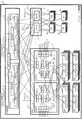
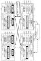
次に、図2及び図3を参照して、図1に示す中継装置2のハードウェア構成例について説明する。図2に示すように、中継装置2は、例示的に、上述した2つのMP20−1及び20−2(#0及び#1)、MPブリッジ21、4つのFRT22(#0〜#3)、並びに2つのSVC23(#0及び#1)をそなえてよい。また、中継装置2は、2つのMP−EXT20a−1及び20a−2(#0及び#1)、並びに2つのMP−PSU20b−1及び20b−2(#0及び#1)をそなえてよい。さらに、中継装置2は、4つのFan Unit(FANU)24(#0〜#3)、並びに4つのPower Supply Unit(PSU)25(#0〜#3)をそなえてよい。[1-2] Hardware Configuration Example-
以下の説明において、中継装置2がそなえる各ユニット(図2に例示する各ブロック)を特定する場合、符号に代えて#0〜#3を用い、例えばMP20−1及び20−2をそれぞれMP#0及びMP#1と表記する場合がある。また、MP−EXT20a−1及び20a−2を単にMP−EXT20aと表記し、MP−PSU20b−1及び20b−2を単にMP−PSU20bと表記する場合がある。なお、「ユニット」は、交換可能な部品であってもよく、「モジュール」と称されてもよい。 In the following description, when each unit (each block illustrated in FIG. 2) included in the
さらに、以下の説明において、MP#0、MP−EXT20a−1、MP−PSU20b−1、FRT#0、FRT#1、SVC#0、FANU#0、FANU#1、PSU#0、及びPSU#1等のモジュールを“#0系”と表記する場合がある。同様に、MP#1、MP−EXT20a−2、MP−PSU20b−2、FRT#2、FRT#3、SVC#1、FANU#2、FANU#3、PSU#2、及びPSU#3等のモジュールを“#1系”と表記する場合がある。換言すれば、#0系及び#1系の各々は、接続部の一例としてのFRT22と監視部の一例としてのSVC23とを含む複数のモジュールを有するモジュール群の一例である。 Furthermore, in the following description,
なお、各CE3におけるCM#0及びCM#1は、中継装置2の#0系及び#1系と、それぞれ対応付けて扱われてもよい。 The
図2に示す例において、各ユニット間の斜線又は淡い網掛けで示す四角は、各ユニットがコネクタによって通信可能に接続されていることを示している。また、各ユニット間の実線、又は、濃い網掛けで示す四角は、各ユニットがコネクタ又はケーブルによって通信可能に接続されていることを示している。 In the example shown in FIG. 2, a shaded square or a shaded square between the units indicates that the units are communicatively connected by a connector. Further, a solid line between the units or a square indicated by a dark mesh indicates that the units are communicatively connected by a connector or a cable.
例えば、図2において、斜線で示す四角は、通常運用におけるマスタSVC監視モードでのSVC23の監視パスを表し、濃い網掛けで示す四角は、MPブリッジ21が故障してSVC独立動作モードに切り替わったときのSVC23の監視パスを表す。なお、図2で図示を省略しているが、中継装置2は、CE#0以外のCE3、例えばCE#1との間でも、CE#0と同様に結線されてよい。 For example, in FIG. 2, the shaded squares represent the monitoring paths of the
MP20は、例えば基板状の装置(基板ユニット)であってもよい。図2に例示するように、#0系及び#1系のMP20にはそれぞれ、MP−EXT20a、MPブリッジ21、FRT22、SVC23、及びFANU24がコネクタを介して相互に通信可能に接続されてもよい。 The
MP−EXT20aは、例えばMP20及びMP−PSU20bと互いに通信可能に接続され、MP20とMP−PSU20bとの間で送受信される信号等を中継してよい。MP−PSU20bは、例えばMP−EXT20a及びPSU25と互いに通信可能に接続されてよい。なお、MP−EXT20a及びMP−PSU20bは基板状の装置であってもよい。 The MP-
MPブリッジ21は、中継装置2内の上述の如き#0系及び#1系の2系統のコンポーネントを相互に通信可能に接続してよい。例えばMPブリッジ21は、MP#0のコネクタに挿抜可能なアダプタとMP#1のコネクタに挿抜可能なアダプタとをそなえてもよく、これらのアダプタを基板上の配線又はケーブル等で結線したユニットであってもよい。 The
FANU24は、中継装置2の各ユニットの冷却を行なう冷却機構の一例である。例えばFANU24は、1以上のファンをそなえ、中継装置2内を通過する気流を生成することにより、中継装置2内の温度を低下させることができる。 The
PSU25は、中継装置2内の各ユニットに電力を供給する電力供給機構の一例である。例えばPSU25は、MP−PSU20b、MP−EXT20a、及びMP20を介して各ユニット22〜24へ電力を供給してもよい。 The
SVC23は、自系のMP20、MP−EXT20a、MP−PSU20b、FRT22、FANU24、及びPSU25の監視及び制御等を行なってよい。また、SVC23は、自系のMP20及びMPブリッジ21を介して、他系のMP20、MP−EXT20a、MP−PSU20b、FRT22、SVC23、FANU24、及びPSU25の監視及び制御等を行なってよい。SVC23の機能構成例については、図4を参照して後述する。 The
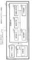
SVC23は、図3に例示するハードウェア構成をそなえてもよい。図3に示すように、SVC23は、例示的に、Central Processing Unit(CPU)2a、メモリ2b、記憶部2c、Interface(IF)部2d、及びInput / Output(I/O)部2eをそなえてよい。 The
CPU2aは、種々の制御や演算を行なうプロセッサの一例である。CPU2aは、各ブロック2b〜2eとバスで相互に通信可能に接続されてよい。なお、プロセッサ等の演算処理装置としては、CPU2aに代えて、電子回路、例えばMicro Processing Unit(MPU)、Application Specific Integrated Circuit(ASIC)、Field Programmable Gate Array(FPGA)等の集積回路(IC)が用いられてもよい。 The
メモリ2bは、種々のデータやプログラムを格納するハードウェアの一例である。メモリ2bとしては、例えばRandom Access Memory(RAM)等の揮発性メモリが挙げられる。 The
記憶部2cは、種々のデータやプログラム等を格納するハードウェアの一例である。記憶部2cとしては、例えばHDD等の磁気ディスク装置、SSD等の半導体ドライブ装置、フラッシュメモリやRead Only Memory(ROM)等の不揮発性メモリ等の各種記憶装置が挙げられる。 The storage unit 2c is an example of hardware that stores various data, programs, and the like. Examples of the storage unit 2c include magnetic disk devices such as HDDs, semiconductor drive devices such as SSDs, and various storage devices such as non-volatile memories such as flash memories and read only memories (ROMs).
例えば記憶部2cは、SVC23の各種機能の全部若しくは一部を実現する制御プログラム200を格納してもよい。CPU2aは、例えば記憶部2cに格納された制御プログラム200をメモリ2bに展開して実行することにより、SVC23の機能を実現できる。 For example, the storage unit 2c may store the
IF部2dは、自系のモジュール(例えばMP20、FRT22、FANU24、及びPSU25等)、CM4、並びに作業者の作業端末等との間の接続及び通信の制御等を行なう通信インタフェースの一例である。例えばIF部2dは、MP20に接続するためのアダプタや、CM4との接続用の複数のインタフェース、作業端末を接続するためのアダプタ(ポート)等をそなえてもよい。なお、制御プログラム200は、図示しないネットワークからIF部2dを介してSVC23にダウンロードされてもよい。 The
また、IF部2dは、記録媒体2fに記録されたデータやプログラムを読み出す読取部をそなえてもよい。読取部は、非一時的なコンピュータ読取可能な記録媒体2fを接続又は挿入可能な接続端子又は装置を含んでもよい。読取部としては、例えばUniversal Serial Bus(USB)等に準拠したアダプタ、記録ディスクへのアクセスを行なうドライブ装置、SDカード等のフラッシュメモリへのアクセスを行なうカードリーダ等が挙げられる。なお、記録媒体2fには制御プログラム200が格納されてもよい。 Further, the
記録媒体2f及び後述する記録媒体4fとしては、例示的に、磁気/光ディスクやフラッシュメモリ等の非一時的な記録媒体が挙げられる。磁気/光ディスクとしては、例示的に、フレキシブルディスク、Compact Disc(CD)、Digital Versatile Disc(DVD)、ブルーレイディスク、Holographic Versatile Disc(HVD)等が挙げられる。フラッシュメモリとしては、例示的に、USBメモリやSDカード等が挙げられる。なお、CDとしては、例示的に、CD−ROM、CD−R、CD−RW等が挙げられる。また、DVDとしては、例示的に、DVD−ROM、DVD−RAM、DVD−R、DVD−RW、DVD+R、DVD+RW等が挙げられる。 Examples of the recording medium 2f and a recording medium 4f described later include non-temporary recording media such as magnetic/optical disks and flash memories. Examples of the magnetic/optical disc include a flexible disc, a Compact Disc (CD), a Digital Versatile Disc (DVD), a Blu-ray disc, and a Holographic Versatile Disc (HVD). Examples of the flash memory include a USB memory and an SD card. Examples of the CD include CD-ROM, CD-R, and CD-RW. Examples of DVD include DVD-ROM, DVD-RAM, DVD-R, DVD-RW, DVD+R, DVD+RW, and the like.
I/O部2eは、マウス、キーボード、操作ボタン等の入力部、並びにディスプレイ等の出力部の少なくとも一部を含むことができる。例えば入力部は、作業者(使用者)等による設定の登録や変更、システムのモード選択(切替)等の各種操作やデータの入力等の作業に用いられてよく、出力部は、作業者等による設定の確認や各種通知等の出力に用いられてもよい。 The I/
上述した中継装置2及びSVC23のハードウェア構成は例示である。従って、中継装置2及びSVC23内でのハードウェアの増減(例えば任意のブロックの追加や削除)、分割、任意の組み合わせでの統合、バスの追加又は省略等は適宜行なわれてもよい。 The hardware configurations of the
・CM4のハードウェア構成例
次に、図1及び図3を参照して、図1に示すCM4のハードウェア構成例について説明する。図3に示すように、CM4は、例示的に、CPU4a、メモリ4b、記憶部4c、IF部4d、及びI/O部4eをそなえてよい。-Hardware Configuration Example of
CPU4a、メモリ4b、及び、記憶部4cは、それぞれ、CPU2a、メモリ2b、及び、記憶部2cと同様であってもよい。なお、メモリ4bは、DE5に対するアクセス等に用いられるデータやプログラムを一時的に記憶するキャッシュメモリとして用いられてもよい。また、記憶部4cは、CM4の各種機能の全部若しくは一部を実現する制御プログラム400を格納してもよい。CPU4aは、例えば記憶部4cに格納された制御プログラム400をメモリ4bに展開して実行することにより、CM4の機能を実現できる。 The
IF部4dは、中継装置2のFRT22やSVC23、ホスト装置、DE5、CE3内の他のCM4、並びに作業者の作業端末等との間の接続及び通信の制御等を行なう通信インタフェースの一例である。例えばIF部4dは、図1に示すIF4d−1〜4d−3や、作業端末を接続するためのアダプタ(ポート)等をそなえてもよい。なお、制御プログラム400は、図示しないネットワークからIF部4dを介してCM4にダウンロードされてもよい。 The
図1に示す例において、IF4d−1は、中継装置2との間の接続及び通信の制御等を行なう通信インタフェースの一例である。IF4d−1としては、例えばPCIe等に準拠したアダプタをそなえるNon Transparent Bridge(NTB)が挙げられる。 In the example illustrated in FIG. 1, the
IF4d−2は、ホスト装置との間の接続及び通信の制御等を行なう通信インタフェース(ホストインタフェース)の一例である。IF4d−2としては、例えばLocal Area Network(LAN)、Storage Area Network(SAN)、Fibre Channel(FC)、InfiniBand(インフィニバンド)等に準拠したアダプタをそなえるChannel Adapter(CA)が挙げられる。IF4d−2は、これらに準拠したケーブル等によってホスト装置と接続されてよく、図示しないネットワークを介してもよい。なお、図1の例では、IF4d−2はCM4に4つ設けられている。 The
IF4d−3は、DE5(記憶装置51)との間の接続及び通信の制御等を行なう通信インタフェースの一例である。IF4d−3は、例えば複数(図1の例では2つ)のI/O Controller(IOC)4gと、Expander(EXP)4hとをそなえてもよい。 The
IOC4gは、DE5へのアクセス(I/O)を制御するI/O制御部の一例である。また、EXP4hは、CM4配下に接続(例えばSAS接続)可能なデバイス数の拡張を行なうためのモジュールの一例である。EXP4hは、SASに対応したケーブル等によってDE5と接続されてもよい。 The IOC 4g is an example of an I/O control unit that controls access (I/O) to the
なお、図1の例では、複数のIOC4gがそれぞれ自身のCM4のEXP4hとCE3内の他のCM4のEXP4hとに接続され、これらのEXP4hはそれぞれCE3に対応するDE5に接続されている。 In the example of FIG. 1, the plurality of IOCs 4g are connected to the
例えばホスト装置からIF4d−2を介して入力されたDE5(記憶装置51)へのアクセス要求は、CPU4a及びIOC4gによりパケット生成が行なわれ、EXP4hを介してDE5へ発行される。また、DE5からの応答はEXP4h及びIOC4gを介してCPU4aに受信され、IF4d−2を介してホスト装置へ返される。 For example, an access request to the DE5 (storage device 51) input from the host device via the IF4d-2 is generated by the
図3の説明に戻り、IF部4dは、記録媒体4fに記録されたデータやプログラムを読み出す読取部をそなえてもよい。読取部は、上述したSVC23のIF部2dがそなえる読取部と同様であってよい。 Returning to the description of FIG. 3, the
I/O部4eは、マウス、キーボード、操作ボタン等の入力部、並びにディスプレイ等の出力部の少なくとも一部を含むことができる。例えば入力部は、作業者(使用者)等による設定の登録や変更、システムのモード選択(切替)等の各種操作やデータの入力等の作業に用いられてよく、出力部は、作業者等による設定の確認や各種通知等の出力に用いられてもよい。 The I/
上述したCM4のハードウェア構成は例示である。従って、CM4内でのハードウェアの増減(例えば任意のブロックの追加や削除)、分割、任意の組み合わせでの統合、バスの追加又は省略等は適宜行なわれてもよい。 The hardware configuration of the
〔1−3〕機能構成例
・SVC23について
次に、図4を参照して、一実施形態に係るSVC23の機能構成例について説明する。図4は、図2に示すSVC23の監視処理に係る機能構成例を示すブロック図である。[1-3] Functional Configuration Example-
図4に示すように、SVC23は、例示的に、動作モード切替部231、監視制御部232、及び、メモリ部233をそなえてよい。動作モード切替部231及び監視制御部232の機能は、CPU2aが実行する制御プログラム200により実現されてもよい。 As illustrated in FIG. 4, the
動作モード切替部231は、CM4からの指示に応じて、監視制御処理の動作モードをマスタSVC監視モードとSVC独立動作モードとの間で切り替える。なお、現在の動作モードは、例えば、SVC23内のメモリ2b等に格納された設定情報に記憶され、設定情報を更新することにより動作モードが切り替えられてもよい。 The operation
図5に動作モードの例を示す。図5に例示するように、マスタSVC監視モードは、マスタSVC23が監視主体となり、MPブリッジ21を経由する第1の通信経路を用いてマスタSVC23−スレーブSVC23間で情報の同期を行なうモードである。マスタSVC監視モードは、例えばMPブリッジ21に故障が発生していない正常時の動作モードである。 FIG. 5 shows an example of the operation mode. As illustrated in FIG. 5, the master SVC monitoring mode is a mode in which the
SVC独立動作モードは、マスタCM4が監視主体となり、マスタCM4とマスタ及びスレーブSVC23との間をそれぞれ接続する通信線を経由する第2の通信経路を用いて、SVC23−CM4間で情報の同期を行なうモードである。SVC独立動作モードは、例えば、MPブリッジ21に故障が発生した場合に移行する動作モードである。SVC独立動作モードでは、MPブリッジ21に代えて、マスタCM4を介した経路によってSVC23間の情報の同期が継続できるため、MPブリッジ21が故障した場合でも、他の部品を縮退せずに#0系及び#1系の冗長動作を継続できる。 In the SVC independent operation mode, the
動作モード切替部231によって切り替えられた監視制御の動作モードに応じて、監視制御部232の動作が図6に示すように変化する。 The operation of the
一例として、図6に示すように、マスタSVC監視モードでは、SVC23で検出されたイベントの情報(例えば障害に関する情報)は、マスタSVC23からマスタCM4へ通知される。一方、SVC独立動作モードでは、当該情報を検出したSVC23がマスタSVC23及びMPブリッジ21を経由せずに直接、マスタCM4に通知する。 As an example, as shown in FIG. 6, in the master SVC monitoring mode, information about an event detected by the SVC 23 (for example, information about a failure) is notified from the
また、図6に示すように、マスタCM4がSVC23の管理する情報(例えば、後述する管理情報233a)を取得する場合、マスタSVC監視モードでは、マスタCM4がマスタSVC23に管理情報233aの送信を依頼する。一方、SVC独立動作モードでは、マスタCM4は、各SVC23(例えば、マスタ/スレーブに関わらず、少なくとも1つのSVC23)に管理情報233aの送信を依頼する。 Further, as shown in FIG. 6, when the
さらに、図6に示すように、マスタCM4がSVC23に対して所定の制御を指示する場合、マスタSVC監視モードでは、マスタCM4がマスタSVC23経由で制御対象のSVC23へ指示を行なう。一方、SVC独立動作モードでは、マスタCM4は、各SVC23(例えば、制御対象のSVC23)に対してマスタSVC23を経由せずに直接、制御を指示する。 Further, as shown in FIG. 6, when the
図4の説明に戻り、メモリ部233は、監視制御部232が管理する管理情報233aを記憶してよい。メモリ部233は、例えば、図3に示すメモリ2bの記憶領域により実現されてもよい。 Returning to the description of FIG. 4, the
管理情報233aとしては、例えば、SVC23の監視制御に用いられる監視情報や、中継装置2におけるシステム情報等の各種情報が挙げられる。 Examples of the
監視制御部232は、中継装置2の監視制御を行なう。例えば、監視制御部232は、以下に例示する手法によって監視情報を取得し、管理情報233aを更新してよい。 The
(i)他系SVC23へのハートビート監視
中継装置2内の各SVC23は、他系のSVC23及びCM4(例えばマスタCM4又は全てのCM4)に対して定期的にハートビート等の信号を送信してもよい。監視制御部232は、他系のSVC23から受信するハートビートの受信結果(受信状況)を、他系SVC23に関する監視情報として取得してもよい。(I) Heartbeat Monitoring to
(ii)入力電源監視
監視制御部232は、各ユニットに入力される電源を監視してもよい。この監視では、他系のMP20全体の停電の発生や、PSU25から当該PSU25の属する系における他のユニットまでの給電経路での部分的な停電の発生等を監視できる。例えば監視制御部232は、MP20や各ユニットへ入力されるDirect Current(DC)電圧等を自系に関する監視情報として取得してもよい。(Ii) Input Power Supply Monitoring The
(iii)状態監視
中継装置2では、各ユニット(又は当該ユニットが接続されたMP20、MP−EXT20a、若しくはMP−PSU20b等)からマスタSVC23へユニットのステータスが通知されてもよい。このステータスには、例えばMP20、MP−EXT20a、又はMP−PSU20b等に対してユニットが接続された状態であることを示すマウント(Mount)や、取り外された状態であることを示すアンマウント(Unmount)等が含まれてもよい。(Iii) State Monitoring In the
なお、監視制御部232は、中継装置2において予め定義されたステータスや、正常又は異常の範囲が定められた測定値等を監視情報として取得してもよい。測定値としては、FANU24におけるファンの回転数や、各ユニットにおける温度等が挙げられる。 The
監視制御部232は、自系又は他系のユニットのハードウェアから受信するハートビート等の監視結果、故障情報、各モジュールのステータス等の情報を、自系又は他系に関する監視情報として取得してよい。 The
また、監視制御部232は、管理情報233aに含まれるシステム情報として、SVC23のファームウェアのバージョン情報や、MP20等のLight Emitting Diode(LED)の点灯状態等のステータスを管理してもよい。 Further, the
なお、監視制御部232は、SVC独立動作モードにおいても、マスタCM4からの指示に応じて、例えば上記(ii)又は(iii)の監視情報等を取得してもよい。一方、上記(i)については、SVC23は、送信先をマスタCM4に変更して、マスタCM4にハートビートを送信してもよい。 Note that the
監視制御部232は、図4に例示するように、情報同期部234、異常通知部235、情報送信部236、制御指示受信部237、及び、MP制御部238をそなえてよい。 The
情報同期部234は、他系のSVC23との間で管理情報233aの同期を行なう。例えば、情報同期部234は、監視制御部232が取得した監視情報を他系のSVC23に通知するとともに、他系のSVC23から受信した監視情報を、管理情報233aにマージすることで同期を行なってよい。また、情報同期部234は、監視情報以外にも、自系のシステム情報等の各種情報を他系のSVC23に対して送受信することで、管理情報233aの同期を行なってよい。 The
なお、マスタSVC監視モードでは、情報同期部234は、MPブリッジ21を介して、SVC23間で上述した情報の同期を行なってよい。 In the master SVC monitoring mode, the
一方、SVC独立動作モードでは、マスタCM4が監視主体となってSVC23間の監視(例えば同期)をSVC23の代わりに行なう。従って、情報同期部234は、マスタCM4からの指示に応じて、管理情報233aの通知先を他系のSVC23からマスタCM4に変更し、マスタCM4に対して管理情報233aを通知してよい。 On the other hand, in the SVC independent operation mode, the
異常通知部235は、管理情報233aに含まれる監視情報に基づいて、中継装置2内の各ユニットが異常であるか否かを判定し、検出した異常に関する情報をCM4へ出力(通知)する。 The
例えば異常通知部235は、上述した(i)〜(iii)のうちのいずれかの監視結果に基づき異常を検出したり、(i)〜(iii)の監視結果のうちの所定の組み合わせによって異常を検出してよい。なお、発生した異常の種別によっては、上述した(i)〜(iii)に係る複数の監視結果について、段階的に又は同様のタイミングで異常が検出されることもある。 For example, the
異常に関する情報には、異常を示すと判定した監視情報の種別(異常の種別)、例えば停電、ハートビート異常、アンマウント等と、異常の発生した異常個所、例えばFRT22やSVC23等のユニットを表す情報とが含まれてもよい。異常通知部235は、このような異常に関する情報を、検出した異常の種別ごとに生成してCM4へ通知してよい。 The information regarding the abnormality includes the type of the monitoring information determined to indicate the abnormality (type of abnormality), for example, power failure, heartbeat abnormality, unmount, etc., and the abnormal portion where the abnormality has occurred, for example, a unit such as FRT22 or SVC23. And may be included. The
中継装置2において発生し得る異常としては、以下に例示するものが挙げられる。なお、以下、いずれかの系統に異常が発生する例を説明する場合には、異常の発生した系統を#1系と仮定し、異常の発生していない系統を#0系と仮定する。 Examples of abnormalities that may occur in the
(I)中継装置2内の片系(#1系)停電
この場合、#0系のSVC23では、入力電源監視によって#1系の全体又は部分的な停電を示す監視情報が取得される。従って、異常通知部235は、入力電源監視に係る監視情報に基づき#1系の全体又は部分的な停電を検出する。(I) One-system (#1 system) power failure in the
また、#1系の全体又は#1系のSVC23を含む部分的な停電が発生した場合、#0系のSVC23では、停電の発生した#1系のSVC23からのハートビートが受信されない。従って、この場合、#0系の異常通知部235は、ハートビート監視に係る監視情報に基づきSVC23から一定期間ハートビートを受信していないと判断し、#1系のSVC23についてハートビート異常を検出する。 Further, when a power failure occurs in the
なお、停電によって動作が停止した#1系のユニットについては、#0系のSVC23へアンマウントを示すステータスが通知されることもある。この場合、異常通知部235は、状態監視に係る監視情報に基づき1以上のユニットのアンマウントを検出する。 Regarding the #1 system unit that has stopped operating due to a power failure, the #0
(II)#1系のSVC23のハングアップ
この場合、#0系のSVC23では、ハングアップした#1系のSVC23からのハートビートが受信されない。従って、#0系の異常通知部235は、ハートビート監視に係る監視情報に基づきSVC23から一定期間ハートビートを受信していないと判断し、#1系のSVC23についてハートビート異常を検出する。(II) Hang-up of the #1
(III)#1系のSVC23の異常
#1系のSVC23の異常には、上記(I)又は(II)以外の異常も含まれる。例えば#1系のSVC23が自身の異常を検出して#0系のSVC23へ通知を行なった場合や、#1系のSVC23のステータス若しくは測定値等が異常の状態若しくは異常値(所定の閾値以上若しくは以下)を示すような場合等が挙げられる。(III) Abnormality of
このような場合、#0系の異常通知部235は、監視情報に基づき#1系のSVC23の異常を検出する。 In such a case, the #0 system
(IV)#1系のSVC23以外の#1系のユニットの異常
#1系のSVC23以外の#1系のユニットの異常には、例えばユニットのステータス若しくは測定値等が異常の状態若しくは異常値(例えば所定の閾値以上若しくは以下)を示すような場合等が挙げられる。一例として、ユニットのステータスが異常の状態(例えばアンマウント)を示す場合や、FANU24におけるファンの回転数や各ユニットにおける温度等の測定値等が異常値を示す場合が挙げられる。(IV) Abnormalities in #1 system units other than the #1 system SVC23 Abnormalities in #1 system units other than the #1 system SVC23 include, for example, the status or measured value of the unit being in an abnormal state or abnormal value ( For example, a case where it is equal to or more than a predetermined threshold value or less) can be cited. As an example, there is a case where the status of the unit indicates an abnormal state (for example, unmount), or a case where the fan rotation speed of the
このような場合、#0系の異常通知部235は、監視情報に基づき#1系のユニットの異常を検出する。なお、このとき、#1系のSVC23によっても同様の異常が検出される。 In such a case, the #0 system
なお、上述した(I)〜(IV)の異常は、マスタSVC23及びスレーブSVC23のいずれによっても検出されてよい。 The above-mentioned abnormalities (I) to (IV) may be detected by both the
(V)MPブリッジ21の異常
一実施形態に係るストレージ装置1では、図1及び図2に例示するように中継装置2内のユニットが2系統で冗長化されている。しかし、これら2系統のユニット間は1つのMPブリッジ21により接続されている。(V) Abnormality of
上述のように、MPブリッジ21については冗長化が図られていないため、MPブリッジ21に故障等の異常が発生すると、中継装置2内の系間通信のアクセスパスが断たれてしまう。従って、マスタSVC23(例えばSVC#0)とスレーブSVC23(例えばSVC#1)との間で互いの状態を確認することができない。 As described above, since the
一例として、図7に示すように、MPブリッジ21に異常が発生した場合、マスタSVC#0は、黒の塗り潰しで示すSVC#1、FRT#2、FRT#3、FANU#2、FANU#3、PSU#2、及びPSU#3へのアクセスが不可能になる。従って、マスタSVC監視モードでは、MPブリッジ21に異常が発生した場合、黒の塗り潰しで示すユニットの監視が不可能になる。 As an example, as shown in FIG. 7, when an abnormality occurs in the
このように、MPブリッジ21に異常が発生した場合、異常通知部235は、MPブリッジ21のアンマウントを検出できるとともに、MPブリッジ21の先に接続された他系の全てのユニットについてもアンマウントを検出する。 As described above, when an abnormality occurs in the
但し、異常通知部235で他系の全てのユニットのアンマウントが検出されたとしても、これらのユニットのアンマウントはMPブリッジ21の異常に起因するものである可能性が高く、実際には他系の全てのユニットが正常である可能性が高い。 However, even if the
そこで、MPブリッジ21及び他系の全ユニットのアンマウントを検出すると、マスタSVC23の異常通知部235は、MPブリッジ21の状態に係る監視情報に基づき、異常個所としてMPブリッジ21を表す情報を含む異常に関する情報をCM4へ通知する。一方、他系のユニット(配下部品)については、異常通知部235は、CM4に対する、当該他系のユニットが異常であることの通知を抑止してよい。 Therefore, when the unmounting of the
なお、異常通知部235は、異常に関する情報をCM4に通知した後に、対応する異常個所が活性交換等により復旧したことを検出した場合、異常個所が復旧したことを示す情報をCM4へ通知してもよい。なお、異常個所が復旧したことは、例えば状態監視においてアンマウントの状態からマウントの状態に変化したこと(切り離されていた他系ユニットが認識されたこと)によって検出されてもよい。 After notifying the
異常通知部235による通知先としては、マスタCM4であってもよいし、複数(例えば全て)のCM4であってもよい。 The notification destination by the
なお、上述のように、SVC23では、マスタSVC23がCM4に対して通知を行なうことができる(通知を行なう権限を有する)ため、マスタSVC監視モードでは、異常個所の通知についてもマスタSVC23が行なえばよい。なお、スレーブSVC23は、マスタSVC23の異常を検出した場合には、自身がマスタSVC23に昇格することで、CM4に対して異常個所の通知を行なってよい。これにより、マスタSVC23において異常が発生しても、CM4は当該異常を確実に認識することができる。 As described above, in the
なお、スレーブSVC23によるマスタSVC23への昇格は、例えばSVC23内のメモリ2b等の記憶装置に格納された設定情報等をスレーブからマスタに更新すること等により行なわれてもよい。 The promotion of the
一方、SVC独立動作モードでは、マスタSVC23及びスレーブSVC23が独立に動作するため、異常又は復旧を検出したSVC23がCM4に通知を行なえばよい(図6参照)。このように、SVC独立動作モードでは、マスタ/スレーブの区別なく、各SVC23がCM4へ通知する権限を有するといえる。 On the other hand, in the SVC independent operation mode, the
情報送信部236は、マスタCM4からの依頼に応じて、管理情報233aの一部又は全部の情報をマスタCM4に送信する。 The
例えば、マスタSVC監視モードでは、マスタSVC23の情報送信部236が管理情報233aをマスタCM4に送信してよい。なお、依頼された管理情報233aがスレーブSVC23の管理する情報である場合、マスタSVC23はスレーブSVC23から当該情報を取得してから(同期してから)、マスタCM4に送信してよい。 For example, in the master SVC monitoring mode, the
一方、SVC独立動作モードでは、マスタ/スレーブに関わらず、各SVC23の情報送信部236が、マスタCM4からの指示に応じて、管理情報233aをマスタCM4に送信してよい。 On the other hand, in the SVC independent operation mode, the
制御指示受信部237は、マスタCM4からの中継装置2の制御に関する制御指示を受信し、当該制御指示をMP制御部238に通知する。 The control
例えば、マスタSVC監視モードでは、マスタSVC23の制御指示受信部237がマスタCM4から制御指示を受信し、制御対象である自系又は他系のSVC23のMP制御部238に当該制御指示を通知する。 For example, in the master SVC monitoring mode, the control
一方、SVC独立動作モードでは、制御対象であるSVC23の制御指示受信部237が、マスタCM4から制御指示を受信し、自身のSVC23内のMP制御部238に当該制御指示を通知する。 On the other hand, in the SVC independent operation mode, the control
MP制御部238は、自系又は他系の制御指示受信部237から受信した制御指示に従って、自系のユニットに対する制御(例えば、LEDやファンの制御、ユニットの縮退又は組込制御等)を行なう。 The
一例として、MP制御部238は、マスタCM4から自系のユニットについて縮退を指示されると、該当ユニットを無効化(disable)又はリセットし、該当ユニットへの電源供給をオフに制御して停止させ、マスタCM4に完了を応答してよい。このようなユニットの縮退は、既知の種々の手法により行なうことが可能であり、個々のユニットに対する詳細な縮退の手順等については、その詳細な説明を省略する。 As an example, when the
・CM4について
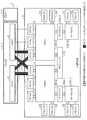
次に、図8を参照して、一実施形態に係るCM4の機能構成例について説明する。図8は、図1に示すCM4の縮退処理に係る機能構成例を示すブロック図である。-CM4 Next, with reference to FIG. 8, a functional configuration example of the CM4 according to the embodiment will be described. FIG. 8 is a block diagram showing a functional configuration example relating to the degeneration process of the
図8に示すように、CM4は、例示的に、動作モード切替部41、監視制御部42、及び、メモリ部43をそなえてよい。 As illustrated in FIG. 8, the
動作モード切替部41は、マスタCM4の監視制御部42における動作モードの切替判定結果に応じて、監視制御の動作モードを切り替える。なお、マスタCM4の動作モード切替部41は、動作モードを切り替える場合、動作モードの切替指示を各SVC23の動作モード切替部231に通知してもよい。 The operation
換言すれば、動作モード切替部41は、第1及び第2のSVC23間で管理情報233aの同期に用いられる通信経路を、MPブリッジ21を経由する第1の通信経路から、第2の通信経路に切り替える切替処理を行なう切替部の一例である。第1の通信経路から第2の通信経路への通信経路の切り替えは、マスタSVC23からMPブリッジ21の異常に関する情報を通知されたことをトリガとして実施されてよい。また、マスタSVC23からMPブリッジ21の復旧に関する情報を受信した場合、動作モード切替部41は、通信経路を第2の通信経路から第1の通信経路に切り替えてよい。 In other words, the operation
メモリ部43は、管理情報43a及び構成情報43bを記憶してよい。メモリ部43は、例えば、図3に示すメモリ4bの記憶領域により実現されてもよい。 The
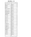
構成情報43bは、マスタCM4が管理する情報であってストレージ装置1の状態を表す情報の一例である。図9に構成情報43bの一例を示す。図9に示すように、構成情報43bには、各ユニットの情報、例えばユニット名と、当該ユニットの状態、例えばonline/offline等とが含まれてもよい。なお、説明のために、図9の例では中継装置2のユニットの状態のみを示しているが、構成情報43bには、ストレージ装置1における他のユニット、例えばCE3やDE5内の部品の状態についても設定され管理されてもよい。 The
構成情報43bは、例えばCM4の出力装置(I/O部4e)やホスト装置、作業端末等に、ストレージ装置1の状態を提示するために用いられてもよい。例えばストレージ装置1の管理者等は、提示された情報に基づき異常個所の交換等を行なうことができる。 The
監視制御部42は、中継装置2を含むストレージ装置1の監視制御を行なう。一実施形態に係る監視制御部42は、SVC独立動作モードにおいて、例えば、SVC23の監視制御部232が行なっていた監視制御の少なくとも一部を代行してもよい。監視制御の少なくとも一部には、管理情報233aの同期、及び、同期した管理情報233aに基づく監視が含まれてもよい。 The
一例として、監視制御部42は、各SVC23において送信先が切り替えられたハートビート等の信号を受信し、上記(i)のハートビート監視を行なってもよい。 As an example, the
監視制御部42は、図8に例示するように、情報取得部44、制御指示送信部45、異常通知受信部46、情報同期部47、判定部48、及び、制御部49をそなえてよい。これらの機能は、CPU4aが実行する制御プログラム400により実現されてもよい。なお、以下の説明では図8に示すCM4がマスタCM4であるものとするが、マスタCM4の異常によりスレーブCM4がマスタCM4に昇格する場合があるため、図8に例示する構成はストレージ装置1内の全てのCM4がそなえてもよい。 As illustrated in FIG. 8, the
情報取得部44は、SVC23から中継装置2に関する情報(例えば管理情報233a)を取得する。例えば、情報取得部44は、マスタSVC監視モードの場合、マスタSVC23に対して情報の取得依頼を送信してよい。 The
また、情報取得部44は、SVC独立動作モードの場合、情報の取得対象のSVC23に対して情報の取得依頼を送信してよい。情報の取得対象が複数のSVC23である場合、情報取得部44は、それぞれのSVC23から管理情報233aを取得し、取得した管理情報233aをマージして管理情報43aとして管理してよい。 In the case of the SVC independent operation mode, the
制御指示送信部45は、SVC23に対して中継装置2に関する制御指示を送信する送信部の一例である。例えば、制御指示送信部45は、マスタSVC監視モードの場合、マスタSVC23に対して制御指示を送信してよい。制御指示の送信先がスレーブSVC23の場合、当該制御指示は、マスタSVC23及び第1の通信経路を介して送信される。 The control
また、制御指示送信部45は、SVC独立動作モードの場合、制御対象のSVC23に対して、第2の通信経路を介して制御指示を送信してよい。 In the SVC independent operation mode, the control
異常通知受信部46は、SVC23から送信された異常に関する情報や異常個所が復旧したことを示す情報等を受信する受信部の一例である。 The abnormality
例えば、異常通知受信部46は、マスタSVC監視モードでは、スレーブSVC23により検出された異常に関する情報を、第1の通信経路及びマスタSVC23を介して受信してよい。 For example, in the master SVC monitoring mode, the abnormality
また、異常通知受信部46は、SVC独立動作モードでは、スレーブSVC23により検出された異常に関する情報を、第2の通信経路を介してスレーブSVC23から受信してよい。 Further, in the SVC independent operation mode, the abnormality
なお、スレーブCM4の異常通知受信部46は、受信した情報をマスタCM4に転送してもよい。これにより、エラー等によりマスタCM4がSVC23からの通知を取得できないような事態を回避することができる。 The abnormality
情報同期部47は、動作モードがSVC独立動作モードの場合に、マスタSVC23に代わってSVC23間の情報の同期を行なう。 The
情報の同期において、情報同期部47は、各SVC23が管理する管理情報233aを各SVC23から取得し、取得した管理情報233aをマージして、管理情報43aとしてメモリ部43に格納(更新)してよい。なお、監視制御部42が監視制御を代行する場合、情報同期部47は、監視制御部42が取得した監視情報についても管理情報43aにマージしてよい。 In the information synchronization, the
このように、情報取得部44及び情報同期部234のいずれか一方又は双方は、SVC独立動作モードにおいて、第2の通信経路を用いて、第1及び第2のSVC23から管理情報233aをそれぞれ取得する取得部の一例である。 As described above, one or both of the
判定部48は、異常通知受信部46から入力される情報、及び、メモリ部43の管理情報43aの少なくとも一方に基づき、制御部49による縮退処理を行なう対象(例えば異常個所)を判定する。 The determining
例えば判定部48は、異常通知受信部46から通知される、上記(I)〜(V)等に基づく異常に関する情報を受けて、当該情報に含まれる異常個所を縮退処理の対象と判定してよい。また、SVC独立動作モードにおいては、判定部48は、管理情報43a内の監視情報に基づき、例えば上記(I)〜(IV)等におけるSVC23を含むユニットの異常を検出し、縮退処理の対象を判定してもよい。 For example, the
なお、判定部48は、複数のユニットについて異常に関する情報を受信した場合、これらのユニットを総合的に判断して、複数のユニットに影響を与え得る1以上のユニットの異常と判断してもよい。この場合、判定部48は、メモリ部43に格納された構成情報43bを参照してもよい。複数のユニットに影響を与え得る1以上のユニットとは、例えばMP20、MP−EXT20a、MP−PSU20b、又はMPブリッジ21等が挙げられる。 In addition, when the
また、判定部48は、MPブリッジ21の異常を通知される、又は、MPブリッジ21の異常を検出すると、動作モード切替部41に対して、動作モードをSVC独立動作モードに移行する指示を行なってよい。なお、動作モードのSVC独立動作モードへの移行は、マスタCM4がマスタ及びスレーブの双方のSVC23に対して生存確認を行ない、双方のSVC23が正常である場合に行なわれてもよい。 When the
例えば、MPブリッジ21に異常が発生する前後にSVC23に異常が発生する場合もある。この場合、異常が発生したSVC23配下のユニットに障害が発生しても、SVC23の異常により当該SVC23配下の各ユニットへのアクセスパスが断たれており、ユニットの障害の検出や対応が困難となる。また、SVC23も異常であるため、マスタCM4から異常の発生したSVC23及び当該SVC23配下のユニットを縮退することも困難となる。 For example, an abnormality may occur in the
このように、MPブリッジ21及びSVC23が異常となった場合、中継装置2におけるクリティカルな障害に対応できなくなる可能性がある。 As described above, when the
そこで、判定部48は、MPブリッジ21及びSVC23の双方が異常である場合には、システム(ストレージ装置1)全体を停止することを制御部49へ指示してもよい。 Therefore, the
なお、MPブリッジ21及びSVC23の双方が異常である場合、異常通知受信部46では、マスタSVC23からMPブリッジ21及びSVC23のそれぞれについて、異常に関する情報が受信される。 When both the
或いは、先にMPブリッジ21に異常が発生した場合、マスタCM4はSVC独立動作モードによりマスタ及びスレーブSVC23の双方の監視を行なっている。この場合において、一方のSVC23に異常が発生すると、判定部48は、監視制御部42によるハートビート監視のエラー、又は、情報同期部47に同期エラー等を検出できる。 Alternatively, if an abnormality occurs in the
このように、判定部48は、種々の手法によってMPブリッジ21及びSVC23の異常を検出できる。 In this way, the
また、判定部48は、異常通知受信部46から異常個所が復旧したことを示す情報(ユニットがマウントされたことの通知)を入力されると、制御部49に対して、該当するユニットについてシステムへの組込処理を指示してよい。 Further, when the
制御部49は、判定部48から指示された縮退処理又は組込処理の対象となるユニットについて、縮退処理(切離処理)又は組込処理を行なう。 The
換言すれば、制御部49は、異常通知受信部46が受信した少なくとも1つのモジュールの異常に関する情報に基づき、中継装置2から異常個所を切り離す切離処理を行なう切離処理部の一例である。 In other words, the
縮退処理には、マスタSVC23又は異常個所を含む系(MP20)のSVC23(例えばスレーブSVC23)に対して、異常個所の動作を停止させる指示を送信する処理が含まれてもよい。また、縮退処理には、構成情報43bに対して異常個所に対応するユニットの状態を無効に設定する処理が含まれてもよい。 The degeneration process may include a process of transmitting an instruction to stop the operation of the abnormal part to the
制御部49による縮退処理としては、縮退処理の対象に応じて以下に例示するような処理が挙げられる。なお、以下、#0系又は#1系に異常が発生する例を説明する場合には、異常の発生した系を#1系と仮定し、異常の発生していない系を#0系と仮定する。 Examples of the degeneracy process performed by the
(a)#1系の個々のユニットの異常(MPブリッジ21が正常の場合)
この場合、マスタSVC監視モードであるため、制御部49は、マスタSVC#0に対して縮退対象のユニットを停止させてよい。また、制御部49は、マスタSVC#0から停止(縮退)の完了を通知されると、縮退対象のユニットの状態を無効化するように構成情報43bを更新してよい。(A) Abnormality of individual units of #1 system (when
In this case, since the master SVC monitoring mode is set, the
なお、構成情報43bの更新において、制御部49は、縮退対象のユニット、例えば“SVC#1”のエントリのステータスを“offline”等の無効を意味する値に設定することで、縮退対象のユニットを無効化してよい。 Note that in updating the
(b)#1系の個々のユニットの異常(MPブリッジ21も異常の場合)
MPブリッジ21が異常の場合、判定部48により動作モードをSVC独立動作モードに切り替える判定が行なわれ、CM4及びSVC23はSVC独立動作モードに移行する。(B) Abnormality of individual units in the #1 system (when the
When the
この場合、異常の発生したユニットがSVC#1であるか否かに応じて、制御部49は以下の処理を行なう。 In this case, the
(b−1)異常の発生したユニットがSVC#1ではない場合
制御部49は、縮退対象のユニットが存在する#1系のSVC#1に対して、当該ユニットを停止させ、SVC#1から停止(縮退)の完了を通知されると、縮退対象のユニットの状態を無効化するように構成情報43bを更新してよい。(B-1) When the Unit in which the Abnormality Occurs is Not
(b−2)異常の発生したユニットがSVC#1である場合
制御部49は、判定部48からシステム全体の停止を指示される。この場合、制御部49は、例えばシステムのシャットダウンを行なうことにより、システムを停止させてよい。一例として、制御部49は、システムの疑似的な停電を発生させ、システムをシャットダウンさせてもよい。(B-2) When the Unit in which the Abnormality Occurs is
これにより、例えば、MPブリッジ21の異常によりアクセスパスが断たれた異常個所についても、冗長化された経路を用いてマスタCM4がシステムから異常個所を切り離すことができる。従って、システムにおけるクリティカルな障害の発生を抑止でき、システムの可用性を向上させることができる。なお、システムのシャットダウンの手法については、既知の種々の手法により行なうことが可能であり、その詳細な説明は省略する。 Thereby, for example, even for an abnormal portion where the access path is cut off due to an abnormality of the
このように、制御部49は、受信した異常に関する情報が、MPブリッジ21及びSVC23の異常に関する情報である場合、ストレージ装置1を停止させる停止処理を行なう停止部の一例である。 As described above, the
次に、制御部49による組込処理について説明する。組込処理では、構成情報43bに対して、復旧したユニットの状態を有効に設定する処理が含まれてもよい。 Next, the incorporation processing by the
一例として、制御部49は、復旧したユニット、例えば“SVC#1”のエントリのステータスを“online”等の有効を意味する値に設定することで、復旧したユニットを有効化することができる。 As an example, the
以上のように、一実施形態に係るストレージ装置1では、CE3及びDE5に加えて、FRT22及びSVC23を含むMP20を複数そなえた中継装置2が新たに設けられている。このような構成において、中継装置2内の異常個所を確実に縮退し、例えば二次故障等の発生を抑止することは、システムの可用性を高める対策の一つとして有効である。 As described above, in the
このため、一実施形態においては、例えば、SVC23により検出された異常に関する情報がCM4に通知され、CM4により、CE3から複数のSVC23への経路を経由して異常個所の縮退処理が行なわれる。これにより、中継装置2内の監視を行なうSVC23が確実に中継装置2内の異常を検出し、ストレージ装置1の制御を行なうCM4が確実に異常個所を縮退することができる。 Therefore, in one embodiment, for example, the
また、CM4は、ストレージ装置1の状態を管理する管理情報(構成情報43b)を保持及び管理することができる。このため、縮退処理や組込処理をCM4に行なわせることで、異常個所(縮退対象)の特定が容易且つ正確に行なえるとともに、縮退や組込が行なわれたユニットの情報を一元管理することができ、システムの管理上の利便性も高い。 Further, the
さらに、CM4は、MPブリッジ21が故障した場合に、マスタSVC23に代わってSVC23間の情報同期を行なうことができる。これにより、MPブリッジ21を経由しないCM4経由の経路によって、SVC23間の監視パスを冗長化でき、システムの可用性を向上できるとともに、MPブリッジ21を冗長化するよりも低コスト又は省スペース化を実現できる。 Further, the
〔1−4〕ストレージ装置の動作例
次に、上述の如く構成されたストレージ装置1の動作例を説明する。なお、便宜上、以下の説明では、マスタCM#0及びマスタSVC#0が#0系に属し、スレーブCM#1及びスレーブSVC#1が#1系に属するものとする。[1-4] Operation Example of Storage Device Next, an operation example of the
〔1−4−1〕MPブリッジが正常の場合の動作例
はじめに、図10及び図11を参照して、MPブリッジ21が正常の場合の動作例を説明する。なお、MPブリッジ21が正常の場合、CM4及びSVC23は、マスタSVC監視モードで動作する。[1-4-1] Operation Example when MP Bridge is Normal First, an operation example when the
図10に例示するように、スレーブSVC#1が自系ユニットの異常を検出すると(処理P1)、当該異常に関する情報をMPブリッジ21経由のSVC23間通信によりマスタSVC#0に通知する(処理P2)。 As illustrated in FIG. 10, when the
マスタSVC#0は、スレーブSVC#1から受信した情報を自身が管理する管理情報233aにマージして管理する(処理P3)。 The
また、スレーブSVC#1は、自系のスレーブCM#1に異常に関する情報を通知する(処理P4)。スレーブCM#1は、当該情報をマスタCM#0に通知する(処理P5)。なお、スレーブSVC#1は、処理P4で自系のスレーブCM#1に当該情報を通知しているが(ストレートラインでの通知)、処理P5をスキップして他系のマスタCM#0に直接通知してもよい(クロスラインでの通知)。 Further, the
マスタCM#0は、異常が発生したユニットについて縮退処理を実施する(処理P6)。縮退処理では、判定部48による縮退対象の判定、構成情報43bの状態更新、制御部49によるマスタSVC#0への縮退指示、及び、例えば管理者に対する異常通知等が含まれてよい。 The
以上の処理により、MPブリッジが正常の場合にSVC23で検出されたイベントがCM4に通知される(図6の「マスタSVC監視モード」における「SVC検出イベントのCMへの通知」参照)。 Through the above process, the event detected by the
また、図10に例示するように、マスタCM#0がSVC23の管理する情報を取得したい場合、情報取得部44は、マスタSVC#0に対して、コマンド送信等により情報取得依頼を行なう(処理P7)。 Further, as illustrated in FIG. 10, when the
マスタSVC#0の情報送信部236は、マスタSVC#0が管理する管理情報233aの一部又は全部をメモリ部233から読み出してマスタCM#0に送信する(処理P8)。 The
マスタCM#0は、マスタSVC#0から情報を取得し(処理P9)、当該情報を用いた処理を行なう。なお、マスタSVC監視モードであるため、両SVC23の情報がマスタSVC#0の管理情報233aにマージ済みである。従って、マスタCM#0は、情報をマスタSVC23から取得することで、両系統の情報を取得できる。 The
以上の処理により、SVC23が管理する情報がマスタCM4によって取得される(図6の「マスタSVC監視モード」における「SVCが管理する情報の取得」参照)。 Through the above processing, the information managed by the
さらに、図10に例示するように、マスタCM#0からSVC23に対して制御指示を行ないたい場合、マスタCM#0の制御指示送信部45は、マスタSVC#0に対して制御指示を送信する(処理P10)。 Further, as illustrated in FIG. 10, when the
マスタSVC#0の制御指示受信部237は、マスタCM#0から受信した制御指示の指示系統を認識する。例えば、マスタSVC#0は、制御指示が自系(#0系)宛ての場合、制御指示に応じた制御を実行する。一方、マスタSVC#0は、制御指示が他系(#1系)宛ての場合、当該制御指示をスレーブSVC#1に通知する(処理P11)。 The control
スレーブSVC#1は、マスタSVC#0から制御指示を受信すると、制御指示に応じた制御を実行する(処理P12)。 Upon receiving the control instruction from the
以上の処理により、CM4からSVC23への制御指示に係る処理が完了する(図6の「マスタSVC監視モード」における「CMからSVCへの制御指示」参照)。 With the above processing, the processing relating to the control instruction from the
以上のように、MPブリッジ21が正常の場合、ストレージ装置1では、図11に黒の塗り潰しで示す動作モード、情報、及び、同期の主体がアクティブとなり、SVC23間の情報同期がMPブリッジ21を経由する監視パスによって実行される。この場合、マスタCM#0は、マスタSVC#0経由で情報の取得や制御を行なうことができる。 As described above, when the
〔1−4−2〕MPブリッジに異常が発生した場合の動作例
次に、図12〜図14を参照して、MPブリッジ21に異常が発生した場合の動作例を説明する。[1-4-2] Example of Operation when Abnormality Occurs in MP Bridge Next, an example of operation when an abnormality occurs in the
図12に例示するように、マスタSVC監視モードにおいて、MPブリッジ21に異常が発生すると(処理P21)、異常を検出したマスタSVC#0は、自系のマスタCM#0にMPブリッジ21の異常を通知する(処理P22)。また、スレーブSVC#1もMPブリッジ21の異常を検出するが(処理P23)、スレーブであるため待機する。 As illustrated in FIG. 12, when an abnormality occurs in the
マスタCM#0は、マスタSVC#0及びスレーブSVC#1のそれぞれに対して生存確認を行なう(処理P24)。マスタSVC#0及びスレーブSVC#1は、それぞれマスタCM#0に対して生存応答を返す(処理P25及びP26)。 The
マスタCM#0の判定部48は、いずれのSVC23も正常であるため、SVC23の動作モードをSVC独立動作モードに決定する(処理P27)。また、マスタCM#0及びスレーブCM#1の動作モード切替部41は、それぞれ、動作モードをSVC独立動作モードに切り替える。なお、処理P25及びP26のうちの少なくとも一方の生存応答がない場合、処理が図13のP46に移行する。 The
また、マスタCM#0の動作モード切替部41は、マスタSVC#0及びスレーブSVC#1に対して、それぞれ、SVC独立動作モードへの移行を指示する(処理P28)。 In addition, the operation
マスタSVC#0及びスレーブSVC#1の動作モード切替部231は、それぞれ、マスタCM#0からの指示に応じて、動作モードをSVC独立動作モードに切り替え(処理P29及びP30)、マスタCM#0に対して応答を送信する。マスタCM#0は、各SVC23から応答を受信し(処理P31)、動作モードの切り替えが終了する。 The operation
また、図12に例示するように、SVC独立動作モードにおいて、スレーブSVC#1は、自系ユニットの異常を検出した場合(処理P32)、当該異常に関する情報を自系のスレーブCM#1に通知する(処理P33)。なお、MPブリッジ21の異常によりSVC23間通信ができないため、当該情報はマスタSVC#0には通知されない。 Further, as illustrated in FIG. 12, in the SVC independent operation mode, when the
スレーブCM#1は、当該情報をCM4−SVC23間の通信パスを介してマスタCM#0に通知する(処理P34)。なお、スレーブSVC#1は、処理P34で自系のスレーブCM#1に通知しているが(ストレートラインでの通知)、処理P34をスキップして他系のマスタCM#0に直接通知してもよい(クロスラインでの通知)。 The
マスタCM#0は、受信した異常に関する情報を管理情報43aにマージして管理し(処理P35)、異常が発生したユニットについて縮退処理を実施する(処理P36)。縮退処理では、判定部48による縮退対象の判定、構成情報43bの状態更新、制御部49によるスレーブSVC#1への縮退指示、管理者に対する異常通知等が含まれてよい。 The
以上の処理により、MPブリッジが異常の場合にSVC23で検出されたイベントがCM4に通知される(図6の「SVC独立動作モード」における「SVC検出イベントのCMへの通知」参照)。 Through the above processing, the event detected by the
また、図13に例示するように、マスタCM#0がSVC23の管理する情報を取得したい場合、情報取得部44は、マスタSVC#0及びスレーブSVC#1の双方に対して、コマンド送信により情報取得依頼を行なう(処理P37)。 Further, as illustrated in FIG. 13, when the
マスタSVC#0及びスレーブSVC#1の情報送信部236は、それぞれ、自身が管理する管理情報233aの一部又は全部をメモリ部233から読み出してマスタCM#0に送信する(処理P38及びP39)。 The
マスタCM#0は、マスタSVC#0及びスレーブSVC#1からそれぞれ情報を取得し(処理P40)、当該情報を管理情報43aにマージして(処理P41)、管理情報43aを用いた処理を行なう。SVC独立動作モードでは、#0系及び#1系の情報がそれぞれの系統(SVC23)で独立して管理されているため、処理P41により、両系統の情報を統合することができる。 The
以上の処理により、SVC23が管理する情報がマスタCM4によって取得される(図6の「SVC独立動作モード」における「SVCが管理する情報の取得」参照)。 Through the above processing, the information managed by the
さらに、図13に例示するように、マスタCM#0からSVC23に対して制御指示を行ないたい場合、マスタCM#0の制御指示送信部45は、マスタSVC#0及びスレーブSVC#1のそれぞれに対して制御指示を送信する(処理P42)。 Further, as illustrated in FIG. 13, when it is desired to issue a control instruction from the
マスタSVC#0の制御指示受信部237は、マスタCM#0から受信した制御指示の指示系統を認識する。例えば、マスタSVC#0は、制御指示が自系(#0系)宛ての場合、制御指示に応じた制御を実行する。一方、マスタSVC#0は、制御指示が他系(#1系)宛ての場合、当該制御指示を読み捨てる(何もしない)(処理P43)。 The control
スレーブSVC#1は、マスタCM#0から受信した制御指示の指示系統を認識する。例えば、スレーブSVC#1は、制御指示が自系(#1系)宛ての場合、制御指示に応じた制御を実行する。一方、スレーブSVC#1は、制御指示が他系(#0系)宛ての場合、当該制御指示を読み捨てる(何もしない)(処理P44)。 The
なお、図13の例では、制御指示がマスタSVC#0及びスレーブSVC#1の双方に送信されているが、指示対象のSVC23のみに送信されてもよい。 In the example of FIG. 13, the control instruction is transmitted to both the
以上の処理により、CM4からSVC23への制御指示に係る処理が完了する(図6の「SVC独立動作モード」における「CMからSVCへの制御指示」参照)。 With the above processing, the processing relating to the control instruction from the
以上のように、MPブリッジ21が異常の場合、ストレージ装置1では、図14に黒の塗り潰しで示す動作モード、情報、及び、同期の主体がアクティブとなり、情報同期がCM4−SVC23間の通信線及びCM4を経由する監視パスによって実行される。この場合、マスタCM#0は、通信線を介して直接的に、制御対象のSVC23に対して情報の取得や制御を行なうことができる。 As described above, when the
また、図13に例示するように、スレーブSVC#1に異常が発生した場合(処理P45)、マスタCM#0は、スレーブSVC#1の異常を検出する(処理P46)。この場合、マスタCM#0は、疑似停電を発生させる等の手法により、システムを停止させ(処理P47)、処理が終了する。 Further, as illustrated in FIG. 13, when an abnormality occurs in the slave SVC #1 (process P45), the
なお、SVC23の異常は、上述のように種々の手法により検出されてよい。例えば、マスタCM#0は、図12の処理P25及びP26の少なくとも一方の生存応答をSVC23から受信しない場合に、SVC23の異常を検出してもよい。また、マスタCM#0は、情報の同期により取得した監視情報に基づき、SVC23の異常を検出してもよい。 The abnormality of the
〔1−4−3〕MPブリッジの復旧の動作例
次に、図15を参照して、MPブリッジ21の復旧の動作例を説明する。[1-4-3] MP Bridge Restoration Operation Example Next, with reference to FIG. 15, an
図15に例示するように、SVC独立動作モードにおいて、故障したMPブリッジ21が交換等により復旧すると(処理P51)、各SVC23は、自系のCM4にMPブリッジ21が復旧したことを通知する(処理P52及びP53)。 As illustrated in FIG. 15, in the SVC independent operation mode, when the failed
スレーブSVC#1から通知を受けたスレーブCM#1は、マスタCM#0にMPブリッジ21が復旧したことを通知する(処理P54)。なお、スレーブSVC#1は、処理P53の通知をスキップしてもよく、或いは、処理P54をスキップしてクロスラインによりマスタCM#0に通知してもよい。 The
マスタSVC#0(及びスレーブCM#1)から通知を受けたマスタCM#0は、マスタSVC#0及びスレーブSVC#1のそれぞれに対して、SVC独立動作モードの解除を指示する(処理P55)。マスタCM#0及びスレーブCM#1の動作モード切替部41は、それぞれ、SVC独立動作モードを解除してマスタSVC監視モードに移行する。 The
マスタSVC#0及びスレーブSVC#1の動作モード切替部231は、それぞれ、マスタCM#0からの指示に応じて、SVC独立動作モードを解除してマスタSVC監視モードに移行し(処理P56及びP57)。マスタCM#0に対して応答を送信する。 The operation
マスタCM#0は、各SVC23から応答を受信し(処理P58)、MPブリッジ21を経由するSVC23間の監視パスが復旧する(処理P59)。これにより、SVC23間での監視情報の同期が可能となる。 The
〔2〕その他
以上、本発明の好ましい実施形態について詳述したが、本発明は、かかる特定の実施形態に限定されるものではなく、本発明の趣旨を逸脱しない範囲内において、種々の変形、変更して実施することができる。[2] Others Although the preferred embodiments of the present invention have been described in detail above, the present invention is not limited to these specific embodiments, and various modifications can be made without departing from the gist of the present invention. It can be changed and implemented.
例えば、図4に示すSVC23の各機能ブロックや図8に示すCM4の各機能ブロックは、それぞれ任意の組み合わせで併合してもよく、分割してもよい。 For example, the functional blocks of the
また、中継装置2内のMP20、MP20内のFRT22、CE3内のCM4の数は、それぞれ2つに限定されるものではなく、それぞれ1又は3以上であってもよい。なお、中継装置2にMP20が3以上そなえられる場合、MPブリッジ21も2以上そなえられてもよい。 Further, the numbers of MP20 in the
〔3〕付記
以上の実施形態に関し、更に以下の付記を開示する。[3] Supplementary notes The following supplementary notes will be disclosed regarding the above-described embodiment.
(付記1)
複数の記憶装置に対するアクセスを制御する複数の制御装置のうちのいずれかの制御装置であって、
前記複数の制御装置間の通信を中継する中継装置がそなえる第1及び第2の監視部のうちの、第1の管理情報を管理し前記中継装置の監視を行なう前記第1の監視部から、前記第1の監視部により検出された前記中継装置内の異常に関する情報を受信する受信部と、
受信した前記異常に関する情報が、前記第1の監視部と、第2の管理情報を管理し前記中継装置の監視を行なう前記第2の監視部と、の間の第1の通信経路を形成するブリッジ部の異常に関する情報である場合、前記第1の監視部と前記第2の監視部との間で前記第1及び第2の管理情報の同期に用いられる通信経路を、前記ブリッジ部を経由する前記第1の通信経路から、前記制御装置と前記第1及び第2の監視部との間をそれぞれ接続する通信線を経由する第2の通信経路に切り替える切替処理を行なう切替部と、をそなえる
ことを特徴とする、制御装置。(Appendix 1)
Which is any one of a plurality of control devices for controlling access to a plurality of storage devices,
Of the first and second monitoring units included in a relay device that relays communication between the plurality of control devices, the first monitoring unit that manages the first management information and monitors the relay device, A receiving unit for receiving information on an abnormality in the relay device detected by the first monitoring unit;
The received information about the abnormality forms a first communication path between the first monitoring unit and the second monitoring unit that manages the second management information and monitors the relay device. If the information is related to the abnormality of the bridge unit, the communication path used for synchronizing the first and second management information between the first monitoring unit and the second monitoring unit is passed through the bridge unit. And a switching unit that performs a switching process of switching from the first communication path to a second communication path that passes through communication lines that respectively connect the control device and the first and second monitoring units. A control device characterized by being provided.
(付記2)
前記切替処理後、前記第2の通信経路を用いて、前記第1及び第2の監視部から前記第1及び第2の管理情報をそれぞれ取得する取得部と、
取得した前記第1及び第2の管理情報に基づいて前記監視を行なう監視制御部と、をそなえる
ことを特徴とする、付記1記載の制御装置。(Appendix 2)
An acquisition unit that acquires the first and second management information from the first and second monitoring units using the second communication path after the switching process,
The control device according to
(付記3)
前記受信部は、前記ブリッジ部に異常が発生していない場合、前記第2の監視部により検出された異常に関する情報を、前記第1の通信経路及び前記第1の監視部を介して受信する一方、前記切替処理後、前記第2の監視部により検出された異常に関する情報を、前記第2の通信経路を介して前記第2の監視部から受信する、
ことを特徴とする、付記1又は付記2記載の制御装置。(Appendix 3)
When no abnormality has occurred in the bridge unit, the receiving unit receives information regarding the abnormality detected by the second monitoring unit via the first communication path and the first monitoring unit. On the other hand, after the switching process, information about the abnormality detected by the second monitoring unit is received from the second monitoring unit via the second communication path.
The control device according to
(付記4)
前記ブリッジ部に異常が発生していない場合、前記第2の監視部に対する制御指示を、前記第1の監視部及び前記第1の通信経路を介して送信する一方、前記切替処理後、前記第2の監視部に対する制御指示を、前記第2の通信経路を介して前記第2の監視部に送信する送信部、をそなえる
ことを特徴とする、付記1〜3のいずれか1項記載の制御装置。(Appendix 4)
When no abnormality has occurred in the bridge unit, a control instruction to the second monitoring unit is transmitted via the first monitoring unit and the first communication path, while the switching process is performed after the switching process. 2. The control according to any one of
(付記5)
前記切替部は、前記第1の監視部から前記ブリッジ部の復旧に関する情報を受信した場合、前記通信経路を、前記第2の通信経路から前記第1の通信経路に切り替える、
ことを特徴とする、付記1〜4のいずれか1項記載の制御装置。(Appendix 5)
The switching unit switches the communication path from the second communication path to the first communication path when receiving information about restoration of the bridge unit from the first monitoring unit.
The control device according to any one of
(付記6)
受信した前記異常に関する情報が、前記ブリッジ部及び前記第2の監視部の異常に関する情報である場合、前記複数の制御装置と前記中継装置とをそなえるストレージ装置を停止させる停止処理を行なう停止部、をそなえる
ことを特徴とする、付記1〜5のいずれか1項記載の制御装置。(Appendix 6)
When the received information on the abnormality is information on the abnormality of the bridge unit and the second monitoring unit, a stop unit that performs a stop process of stopping a storage device including the plurality of control devices and the relay device, The control device according to any one of
(付記7)
受信した前記異常に関する情報が、前記複数の制御装置の各々を相互に通信可能に接続する第1の接続部と前記第1の監視部とを含む複数のモジュールを有する第1のモジュール群、又は、前記複数の制御装置の各々を相互に通信可能に接続する第2の接続部とを含む複数のモジュールを有する第2のモジュール群における、少なくとも1つのモジュールの異常に関する情報である場合、前記中継装置から異常個所を切り離す切離処理を行なう切離処理部、をそなえる
ことを特徴とする、付記1〜6のいずれか1項記載の制御装置。(Appendix 7)
The received information on the abnormality includes a first module group having a plurality of modules including a first connection unit that connects each of the plurality of control devices so that they can communicate with each other, and the first monitoring unit, or , The relay in the case of information on an abnormality of at least one module in a second module group having a plurality of modules including a second connection unit that connects each of the plurality of control devices so that they can communicate with each other. 7. The control device according to any one of
(付記8)
複数の記憶装置に対するアクセスを制御する複数の制御装置と、
前記複数の制御装置間の通信を中継する中継装置と、をそなえ、
前記中継装置は、
第1の管理情報を管理し前記中継装置の監視を行なう第1の監視部と、
第2の管理情報を管理し前記中継装置の監視を行なう第2の監視部と、
前記第1の監視部と前記第2の監視部との間の第1の通信経路を形成するブリッジ部と、をそなえ、
前記複数の制御装置のうちのいずれかの制御装置は、
前記第1の監視部から、前記第1の監視部により検出された前記ブリッジ部の異常に関する情報を受信した場合、前記第1の監視部と前記第2の監視部との間で前記第1及び第2の管理情報の同期に用いられる通信経路を、前記ブリッジ部を経由する前記第1の通信経路から、前記制御装置と前記第1及び第2の監視部との間をそれぞれ接続する通信線を経由する第2の通信経路に切り替える切替処理を行なう、
ことを特徴とする、ストレージ装置。(Appendix 8)
A plurality of control devices for controlling access to a plurality of storage devices,
A relay device for relaying communication between the plurality of control devices,
The relay device is
A first monitoring unit that manages first management information and monitors the relay device;
A second monitoring unit that manages second management information and monitors the relay device;
A bridge unit forming a first communication path between the first monitoring unit and the second monitoring unit,
Any one of the plurality of control devices,
When the information regarding the abnormality of the bridge unit detected by the first monitoring unit is received from the first monitoring unit, the first monitoring unit and the second monitoring unit are connected to each other. And a communication path used for synchronizing the second management information, the communication path connecting the control device and the first and second monitoring sections from the first communication path passing through the bridge section. Perform a switching process for switching to a second communication path passing through the line,
A storage device characterized by the above.
(付記9)
前記制御装置は、
前記切替処理後、前記第2の通信経路を用いて、前記第1及び第2の監視部から前記第1及び第2の管理情報をそれぞれ取得し、
取得した前記第1及び第2の管理情報に基づいて前記監視を行なう、
ことを特徴とする、付記8記載のストレージ装置。(Appendix 9)
The control device is
After the switching process, the second communication path is used to obtain the first and second management information from the first and second monitoring units, respectively.
The monitoring is performed based on the acquired first and second management information,
The storage device according to appendix 8, characterized in that.
(付記10)
前記制御装置は、
前記ブリッジ部に異常が発生していない場合、前記第2の監視部により検出された異常に関する情報の受信、及び、前記第2の監視部に対する制御指示の送信、の少なくとも一方を、前記第1の監視部及び前記第1の通信経路を介して行ない、
前記切替処理後、前記第2の監視部により検出された異常に関する情報の受信、及び、前記第2の監視部に対する制御指示の送信、の少なくとも一方を、前記第2の通信経路を介して行なう、
ことを特徴とする、付記8又は付記9記載のストレージ装置。(Appendix 10)
The control device is
When no abnormality has occurred in the bridge unit, at least one of reception of information regarding the abnormality detected by the second monitoring unit and transmission of a control instruction to the second monitoring unit is performed by the first Via the monitoring unit and the first communication path of
After the switching process, at least one of receiving information about an abnormality detected by the second monitoring unit and transmitting a control instruction to the second monitoring unit is performed via the second communication path. ,
The storage device according to supplementary note 8 or supplementary note 9, characterized in that
(付記11)
前記制御装置は、
前記第1の監視部から前記ブリッジ部の復旧に関する情報を受信した場合、前記通信経路を、前記第2の通信経路から前記第1の通信経路に切り替える、
ことを特徴とする、付記8〜10のいずれか1項記載のストレージ装置。(Appendix 11)
The control device is
Switching the communication path from the second communication path to the first communication path when receiving information on restoration of the bridge section from the first monitoring section,
11. The storage device according to any one of appendices 8 to 10, characterized in that.
(付記12)
前記制御装置は、
受信した前記異常に関する情報が、前記ブリッジ部及び前記第2の監視部の異常に関する情報である場合、前記ストレージ装置を停止させる停止処理を行なう、
ことを特徴とする、付記8〜11のいずれか1項記載のストレージ装置。(Appendix 12)
The control device is
When the received information on the abnormality is information on the abnormality of the bridge unit and the second monitoring unit, stop processing for stopping the storage device is performed.
12. The storage device according to any one of appendices 8 to 11, characterized in that.
(付記13)
前記中継装置は、
前記複数の制御装置の各々を相互に通信可能に接続する第1の接続部と前記第1の監視部とを含む複数のモジュールを有する第1のモジュール群と、
前記複数の制御装置の各々を相互に通信可能に接続する第2の接続部と前記第2の監視部とを含む複数のモジュールを有する第2のモジュール群と、をそなえ、
前記制御装置は、
受信した前記異常に関する情報が、前記第1又は第2のモジュール群における少なくとも1つのモジュールの異常に関する情報である場合、前記中継装置から異常個所を切り離す切離処理を行なう、
ことを特徴とする、付記8〜12のいずれか1項記載のストレージ装置。(Appendix 13)
The relay device is
A first module group having a plurality of modules including a first connection unit that connects each of the plurality of control devices so that they can communicate with each other, and the first monitoring unit;
A second module group having a plurality of modules including a second connection unit that connects each of the plurality of control devices to each other so that they can communicate with each other, and a second module group,
The control device is
When the received information on the abnormality is information on the abnormality of at least one module in the first or second module group, a disconnection process for disconnecting the abnormal portion from the relay device is performed.
13. The storage device according to any one of appendices 8 to 12, characterized in that.
(付記14)
複数の記憶装置に対するアクセスを制御する複数のコンピュータのうちのいずれかのコンピュータに、
前記複数のコンピュータ間の通信を中継する中継装置がそなえる第1及び第2の監視部のうちの、第1の管理情報を管理し前記中継装置の監視を行なう前記第1の監視部から、前記第1の監視部により検出された前記中継装置内の異常に関する情報を受信し、
受信した前記異常に関する情報が、前記第1の監視部と、第2の管理情報を管理し前記中継装置の監視を行なう前記第2の監視部と、の間の第1の通信経路を形成するブリッジ部の異常に関する情報である場合、前記第1の監視部と前記第2の監視部との間で前記第1及び第2の管理情報の同期に用いられる通信経路を、前記ブリッジ部を経由する前記第1の通信経路から、前記コンピュータと前記第1及び第2の監視部との間をそれぞれ接続する通信線を経由する第2の通信経路に切り替える切替処理を行なう、
処理を実行させることを特徴とする、制御プログラム。(Appendix 14)
Any one of the plurality of computers that controls access to the plurality of storage devices,
From the first monitoring unit that manages the first management information and monitors the relay device, of the first and second monitoring units included in the relay device that relays communication between the plurality of computers, Receiving information about an abnormality in the relay device detected by the first monitoring unit,
The received information about the abnormality forms a first communication path between the first monitoring unit and the second monitoring unit that manages the second management information and monitors the relay device. If the information is related to the abnormality of the bridge unit, the communication path used for synchronizing the first and second management information between the first monitoring unit and the second monitoring unit is passed through the bridge unit. A switching process for switching from the first communication path to a second communication path via a communication line connecting between the computer and the first and second monitoring units, respectively.
A control program that causes processing to be executed.
(付記15)
前記コンピュータに、
前記切替処理後、前記第2の通信経路を用いて、前記第1及び第2の監視部から前記第1及び第2の管理情報をそれぞれ取得し、
取得した前記第1及び第2の管理情報に基づいて前記監視を行なう、
処理を実行させることを特徴とする、付記14記載の制御プログラム。(Appendix 15)
On the computer,
After the switching process, the second communication path is used to obtain the first and second management information from the first and second monitoring units, respectively.
The monitoring is performed based on the acquired first and second management information,
14. The control program according to appendix 14, which is characterized by causing processing to be executed.
(付記16)
前記コンピュータに、
前記ブリッジ部に異常が発生していない場合、前記第2の監視部により検出された異常に関する情報の受信、及び、前記第2の監視部に対する制御指示の送信、の少なくとも一方を、前記第1の監視部及び前記第1の通信経路を介して行ない、
前記切替処理後、前記第2の監視部により検出された異常に関する情報の受信、及び、前記第2の監視部に対する制御指示の送信、の少なくとも一方を、前記第2の通信経路を介して行なう、
処理を実行させることを特徴とする、付記14又は付記15記載の制御プログラム。(Appendix 16)
On the computer,
When no abnormality has occurred in the bridge unit, at least one of reception of information regarding the abnormality detected by the second monitoring unit and transmission of a control instruction to the second monitoring unit is performed by the first Via the monitoring unit and the first communication path of
After the switching process, at least one of receiving information about an abnormality detected by the second monitoring unit and transmitting a control instruction to the second monitoring unit is performed via the second communication path. ,
The control program according to supplementary note 14 or supplementary note 15, characterized in that the control program is executed.
(付記17)
前記コンピュータに、
前記第1の監視部から前記ブリッジ部の復旧に関する情報を受信した場合、前記通信経路を、前記第2の通信経路から前記第1の通信経路に切り替える、
処理を実行させることを特徴とする、付記14〜16のいずれか記載の制御プログラム。(Appendix 17)
On the computer,
Switching the communication path from the second communication path to the first communication path when receiving information on restoration of the bridge section from the first monitoring section,
17. The control program according to any one of appendices 14 to 16, characterized in that the control program is executed.
(付記18)
前記コンピュータに、
受信した前記異常に関する情報が、前記ブリッジ部及び前記第2の監視部の異常に関する情報である場合、前記複数のコンピュータと前記中継装置とをそなえるストレージ装置を停止させる停止処理を行なう、
処理を実行させることを特徴とする、付記14〜17のいずれか1項記載の制御プログラム。(Appendix 18)
On the computer,
When the received information on the abnormality is information on the abnormality of the bridge unit and the second monitoring unit, a stop process for stopping the storage device including the plurality of computers and the relay device is performed.
18. The control program according to any one of appendices 14 to 17, characterized in that the control program is executed.
(付記19)
前記コンピュータに、
受信した前記異常に関する情報が、前記複数のコンピュータの各々を相互に通信可能に接続する第1の接続部と前記第1の監視部とを含む複数のモジュールを有する第1のモジュール群、又は、前記複数のコンピュータの各々を相互に通信可能に接続する第2の接続部とを含む複数のモジュールを有する第2のモジュール群における、少なくとも1つのモジュールの異常に関する情報である場合、前記中継装置から異常個所を切り離す切離処理を行なう、
処理を実行させることを特徴とする、付記14〜18のいずれか1項記載の制御プログラム。(Appendix 19)
On the computer,
The received information about the abnormality includes a first module group having a plurality of modules including a first connection unit that connects each of the plurality of computers so that they can communicate with each other, and the first monitoring unit, or From the relay device, when the information is related to an abnormality of at least one module in a second module group having a plurality of modules including a second connection unit that connects each of the plurality of computers so that they can communicate with each other. Performs disconnection processing to disconnect the abnormal part,
The control program according to any one of appendices 14 to 18, characterized in that the control program is executed.
1 ストレージ装置
2 中継装置
3、3−1〜3−n コントローラエンクロージャ(CE)
4 コントローラモジュール(CM)
5 ドライブエンクロージャ(DE)
20、20−1、20−2 ミッドプレーン(MP)
20a、20a−1、20a−2 MP−EXT
20b、20b−1、20b−2 MP−PSU
21 MPブリッジ
22 フロントエンドルータ(FRT)
23 サービスコントローラ(SVC)
24 FANU
25 PSU
41、231 動作モード切替部
42、232 監視制御部
43、233 メモリ部
43a、233a 管理情報
43b 構成情報
44 情報取得部
45 制御指示送信部
46 異常通知受信部
47、234 情報同期部
48 判定部
49 制御部
51 記憶装置
235 異常通知部
236 情報送信部
237 制御指示受信部
238 MP制御部1
4 Controller module (CM)
5 drive enclosure (DE)
20, 20-1, 20-2 Midplane (MP)
20a, 20a-1, 20a-2 MP-EXT
20b, 20b-1, 20b-2 MP-PSU
21
23 Service Controller (SVC)
24 FANU
25 PSU
41, 231 Operation
Claims (8)
Translated fromJapanese前記複数の制御装置間の通信を中継する中継装置がそなえる第1及び第2の監視部のうちの、第1の管理情報を管理し前記中継装置の監視を行なう前記第1の監視部から、前記第1の監視部により検出された前記中継装置内の異常に関する情報を受信する受信部と、
受信した前記異常に関する情報が、前記第1の監視部と、第2の管理情報を管理し前記中継装置の監視を行なう前記第2の監視部と、の間の第1の通信経路を形成するブリッジ部の異常に関する情報である場合、前記第1の監視部と前記第2の監視部との間で前記第1及び第2の管理情報の同期に用いられる通信経路を、前記ブリッジ部を経由する前記第1の通信経路から、前記制御装置と前記第1及び第2の監視部との間をそれぞれ接続する通信線を経由する第2の通信経路に切り替える切替処理を行なう切替部と、をそなえる
ことを特徴とする、制御装置。Which is any one of a plurality of control devices for controlling access to a plurality of storage devices,
Of the first and second monitoring units included in a relay device that relays communication between the plurality of control devices, the first monitoring unit that manages the first management information and monitors the relay device, A receiving unit for receiving information on an abnormality in the relay device detected by the first monitoring unit;
The received information about the abnormality forms a first communication path between the first monitoring unit and the second monitoring unit that manages the second management information and monitors the relay device. If the information is related to the abnormality of the bridge unit, the communication path used for synchronizing the first and second management information between the first monitoring unit and the second monitoring unit is passed through the bridge unit. And a switching unit that performs switching processing for switching from the first communication path to a second communication path that passes through communication lines that respectively connect the control device and the first and second monitoring units. A control device characterized by being provided.
取得した前記第1及び第2の管理情報に基づいて前記監視を行なう監視制御部と、をそなえる
ことを特徴とする、請求項1記載の制御装置。An acquisition unit that acquires the first and second management information from the first and second monitoring units using the second communication path after the switching process,
The control device according to claim 1, further comprising: a monitoring control unit that performs the monitoring based on the acquired first and second management information.
ことを特徴とする、請求項1又は請求項2記載の制御装置。When no abnormality has occurred in the bridge unit, the receiving unit receives information regarding the abnormality detected by the second monitoring unit via the first communication path and the first monitoring unit. On the other hand, after the switching process, information about the abnormality detected by the second monitoring unit is received from the second monitoring unit via the second communication path.
The control device according to claim 1 or 2, characterized in that.
ことを特徴とする、請求項1〜3のいずれか1項記載の制御装置。The switching unit switches the communication path from the second communication path to the first communication path when receiving information about restoration of the bridge unit from the first monitoring unit.
The control device according to any one of claims 1 to 3, which is characterized in that.
ことを特徴とする、請求項1〜4のいずれか1項記載の制御装置。When the received information on the abnormality is information on the abnormality of the bridge unit and the second monitoring unit, a stop unit that performs a stop process of stopping a storage device including the plurality of control devices and the relay device, The control device according to any one of claims 1 to 4, further comprising:
ことを特徴とする、請求項1〜5のいずれか1項記載の制御装置。The received information on the abnormality includes a first module group having a plurality of modules including a first connection unit that connects each of the plurality of control devices so that they can communicate with each other, and the first monitoring unit, or , The relay in the case of information on an abnormality of at least one module in a second module group having a plurality of modules including a second connection unit that connects each of the plurality of control devices so that they can communicate with each other. The control device according to any one of claims 1 to 5, further comprising a disconnection processing unit that performs a disconnection process for disconnecting an abnormal portion from the device.
前記複数の制御装置間の通信を中継する中継装置と、をそなえ、
前記中継装置は、
第1の管理情報を管理し前記中継装置の監視を行なう第1の監視部と、
第2の管理情報を管理し前記中継装置の監視を行なう第2の監視部と、
前記第1の監視部と前記第2の監視部との間の第1の通信経路を形成するブリッジ部と、をそなえ、
前記複数の制御装置のうちのいずれかの制御装置は、
前記第1の監視部から、前記第1の監視部により検出された前記ブリッジ部の異常に関する情報を受信した場合、前記第1の監視部と前記第2の監視部との間で前記第1及び第2の管理情報の同期に用いられる通信経路を、前記ブリッジ部を経由する前記第1の通信経路から、前記制御装置と前記第1及び第2の監視部との間をそれぞれ接続する通信線を経由する第2の通信経路に切り替える切替処理を行なう、
ことを特徴とする、ストレージ装置。A plurality of control devices for controlling access to a plurality of storage devices,
A relay device for relaying communication between the plurality of control devices,
The relay device is
A first monitoring unit that manages first management information and monitors the relay device;
A second monitoring unit that manages second management information and monitors the relay device;
A bridge unit forming a first communication path between the first monitoring unit and the second monitoring unit,
Any one of the plurality of control devices,
When the information regarding the abnormality of the bridge unit detected by the first monitoring unit is received from the first monitoring unit, the first monitoring unit and the second monitoring unit are connected to each other. And a communication path used for synchronizing the second management information, the communication path connecting the control device and the first and second monitoring sections from the first communication path passing through the bridge section. Perform a switching process for switching to a second communication path passing through the line,
A storage device characterized by the above.
前記複数のコンピュータ間の通信を中継する中継装置がそなえる第1及び第2の監視部のうちの、第1の管理情報を管理し前記中継装置の監視を行なう前記第1の監視部から、前記第1の監視部により検出された前記中継装置内の異常に関する情報を受信し、
受信した前記異常に関する情報が、前記第1の監視部と、第2の管理情報を管理し前記中継装置の監視を行なう前記第2の監視部と、の間の第1の通信経路を形成するブリッジ部の異常に関する情報である場合、前記第1の監視部と前記第2の監視部との間で前記第1及び第2の管理情報の同期に用いられる通信経路を、前記ブリッジ部を経由する前記第1の通信経路から、前記コンピュータと前記第1及び第2の監視部との間をそれぞれ接続する通信線を経由する第2の通信経路に切り替える切替処理を行なう、
処理を実行させることを特徴とする、制御プログラム。Any one of the plurality of computers that controls access to the plurality of storage devices,
From the first monitoring unit that manages the first management information and monitors the relay device, of the first and second monitoring units included in the relay device that relays communication between the plurality of computers, Receiving information about an abnormality in the relay device detected by the first monitoring unit,
The received information about the abnormality forms a first communication path between the first monitoring unit and the second monitoring unit that manages the second management information and monitors the relay device. If the information is related to the abnormality of the bridge unit, the communication path used for synchronizing the first and second management information between the first monitoring unit and the second monitoring unit is passed through the bridge unit. A switching process for switching from the first communication path to a second communication path via a communication line connecting between the computer and the first and second monitoring units, respectively.
A control program that causes processing to be executed.
Priority Applications (2)
| Application Number | Priority Date | Filing Date | Title |
|---|---|---|---|
| JP2016154247AJP6750380B2 (en) | 2016-08-05 | 2016-08-05 | Control device, storage device, and control program |
| US15/658,453US10454757B2 (en) | 2016-08-05 | 2017-07-25 | Control apparatus, storage apparatus, and non-transitory computer-readable recording medium having stored therein control program |
Applications Claiming Priority (1)
| Application Number | Priority Date | Filing Date | Title |
|---|---|---|---|
| JP2016154247AJP6750380B2 (en) | 2016-08-05 | 2016-08-05 | Control device, storage device, and control program |
Publications (2)
| Publication Number | Publication Date |
|---|---|
| JP2018022405A JP2018022405A (en) | 2018-02-08 |
| JP6750380B2true JP6750380B2 (en) | 2020-09-02 |
Family
ID=61069623
Family Applications (1)
| Application Number | Title | Priority Date | Filing Date |
|---|---|---|---|
| JP2016154247AActiveJP6750380B2 (en) | 2016-08-05 | 2016-08-05 | Control device, storage device, and control program |
Country Status (2)
| Country | Link |
|---|---|
| US (1) | US10454757B2 (en) |
| JP (1) | JP6750380B2 (en) |
Families Citing this family (1)
| Publication number | Priority date | Publication date | Assignee | Title |
|---|---|---|---|---|
| CN111997928B (en)* | 2020-08-06 | 2022-06-03 | 北京浪潮数据技术有限公司 | JBOF fan control system |
Family Cites Families (19)
| Publication number | Priority date | Publication date | Assignee | Title |
|---|---|---|---|---|
| JP3732869B2 (en) | 1995-06-07 | 2006-01-11 | 株式会社日立製作所 | External storage device |
| JPH11205324A (en)* | 1998-01-12 | 1999-07-30 | Fujitsu Ltd | Circuit backup system in ATM network |
| US6708283B1 (en)* | 2000-04-13 | 2004-03-16 | Stratus Technologies, Bermuda Ltd. | System and method for operating a system with redundant peripheral bus controllers |
| JP4030880B2 (en)* | 2003-01-07 | 2008-01-09 | Necインフロンティア株式会社 | Synchronization clock supply system and synchronization clock supply method |
| JP2004341982A (en) | 2003-05-19 | 2004-12-02 | Hitachi Ltd | Storage controller maintenance management system |
| JP3838992B2 (en)* | 2003-05-21 | 2006-10-25 | エヌイーシーシステムテクノロジー株式会社 | Fault detection method and information processing system |
| JP3776438B2 (en) | 2004-12-03 | 2006-05-17 | 株式会社日立製作所 | Storage device |
| JP2007087266A (en) | 2005-09-26 | 2007-04-05 | Hitachi Ltd | Storage system and storage device |
| JP5060057B2 (en)* | 2006-03-08 | 2012-10-31 | 富士通株式会社 | Communication line monitoring system, relay device, and communication line monitoring method |
| JP2008033588A (en) | 2006-07-28 | 2008-02-14 | Hitachi Ltd | Information processing device |
| JP5998677B2 (en)* | 2012-06-29 | 2016-09-28 | 富士通株式会社 | Storage device and connection device |
| JP6244970B2 (en)* | 2014-02-21 | 2017-12-13 | 富士通株式会社 | Storage system, control device, and control program |
| JP6326907B2 (en)* | 2014-03-27 | 2018-05-23 | 富士通株式会社 | Transmission system, transmission apparatus, and clock synchronization method |
| JP6189783B2 (en)* | 2014-04-08 | 2017-08-30 | APRESIA Systems株式会社 | Relay system and switch device |
| JP6333056B2 (en)* | 2014-05-14 | 2018-05-30 | APRESIA Systems株式会社 | Relay system and switch device |
| JP6222367B2 (en)* | 2014-08-19 | 2017-11-01 | 日本電気株式会社 | COMMUNICATION DEVICE, COMMUNICATION SYSTEM, AND COMMUNICATION METHOD |
| JP6515524B2 (en)* | 2014-12-22 | 2019-05-22 | 富士通株式会社 | Communication system, management device, control device and program |
| JP6582523B2 (en)* | 2015-04-30 | 2019-10-02 | 富士通株式会社 | Storage device, control device, control program |
| JP2017058858A (en)* | 2015-09-15 | 2017-03-23 | 株式会社東芝 | Communication device, communication method, and computer program |
- 2016
- 2016-08-05JPJP2016154247Apatent/JP6750380B2/enactiveActive
- 2017
- 2017-07-25USUS15/658,453patent/US10454757B2/enactiveActive
Also Published As
| Publication number | Publication date |
|---|---|
| US10454757B2 (en) | 2019-10-22 |
| JP2018022405A (en) | 2018-02-08 |
| US20180041381A1 (en) | 2018-02-08 |
Similar Documents
| Publication | Publication Date | Title |
|---|---|---|
| US7809983B2 (en) | Storage system that finds occurrence of power source failure | |
| US7194655B2 (en) | Method and system for autonomously rebuilding a failed server and a computer system utilizing the same | |
| US20070214318A1 (en) | Disk array system and fault-tolerant control method for the same | |
| WO2011141963A1 (en) | Information processing apparatus and data transfer method | |
| US10268560B2 (en) | Bus connection target device, storage control device and bus communication system | |
| JP2017010390A (en) | Storage control device, storage control program, and storage control method | |
| JP2007280258A (en) | Storage controller | |
| JP2008065561A (en) | Storage system and storage system control method | |
| JP2005339216A (en) | Storage control system | |
| JP2007086972A (en) | Storage system, duplex control method, and program | |
| US20160246746A1 (en) | Sas configuration management | |
| US20160320993A1 (en) | Control apparatus and storage system | |
| JP6750380B2 (en) | Control device, storage device, and control program | |
| US7568119B2 (en) | Storage control device and storage control device path switching method | |
| US9542273B2 (en) | Storage control apparatus, storage control system, and storage control method for failure detection and configuration of cascaded storage cabinets | |
| JP6244970B2 (en) | Storage system, control device, and control program | |
| JP6582523B2 (en) | Storage device, control device, control program | |
| JP4252551B2 (en) | Data storage system and log data output method in case of abnormality of storage control device | |
| US7426658B2 (en) | Data storage system and log data equalization control method for storage control apparatus | |
| JP4620502B2 (en) | Disk array device | |
| JP2007018034A (en) | Control apparatus and control method | |
| US7486083B2 (en) | Managing system stability | |
| JP7524701B2 (en) | Control device and control method | |
| US10977107B2 (en) | Apparatus and method to control a storage device | |
| KR20000045771A (en) | Apparatus and method for duplicating data storage unit in atm switching system |
Legal Events
| Date | Code | Title | Description |
|---|---|---|---|
| A621 | Written request for application examination | Free format text:JAPANESE INTERMEDIATE CODE: A621 Effective date:20190513 | |
| RD04 | Notification of resignation of power of attorney | Free format text:JAPANESE INTERMEDIATE CODE: A7424 Effective date:20190607 | |
| A977 | Report on retrieval | Free format text:JAPANESE INTERMEDIATE CODE: A971007 Effective date:20200514 | |
| TRDD | Decision of grant or rejection written | ||
| A01 | Written decision to grant a patent or to grant a registration (utility model) | Free format text:JAPANESE INTERMEDIATE CODE: A01 Effective date:20200714 | |
| A61 | First payment of annual fees (during grant procedure) | Free format text:JAPANESE INTERMEDIATE CODE: A61 Effective date:20200727 | |
| R150 | Certificate of patent or registration of utility model | Ref document number:6750380 Country of ref document:JP Free format text:JAPANESE INTERMEDIATE CODE: R150 |