JP6749847B2 - Balloon catheter - Google Patents
Balloon catheterDownload PDFInfo
- Publication number
- JP6749847B2 JP6749847B2JP2016571804AJP2016571804AJP6749847B2JP 6749847 B2JP6749847 B2JP 6749847B2JP 2016571804 AJP2016571804 AJP 2016571804AJP 2016571804 AJP2016571804 AJP 2016571804AJP 6749847 B2JP6749847 B2JP 6749847B2
- Authority
- JP
- Japan
- Prior art keywords
- balloon
- end side
- connecting portion
- inner tube
- fixed
- Prior art date
- Legal status (The legal status is an assumption and is not a legal conclusion. Google has not performed a legal analysis and makes no representation as to the accuracy of the status listed.)
- Active
Links
Images


Classifications
- A—HUMAN NECESSITIES
- A61—MEDICAL OR VETERINARY SCIENCE; HYGIENE
- A61M—DEVICES FOR INTRODUCING MEDIA INTO, OR ONTO, THE BODY; DEVICES FOR TRANSDUCING BODY MEDIA OR FOR TAKING MEDIA FROM THE BODY; DEVICES FOR PRODUCING OR ENDING SLEEP OR STUPOR
- A61M29/00—Dilators with or without means for introducing media, e.g. remedies
- A61M29/02—Dilators made of swellable material
- A—HUMAN NECESSITIES
- A61—MEDICAL OR VETERINARY SCIENCE; HYGIENE
- A61M—DEVICES FOR INTRODUCING MEDIA INTO, OR ONTO, THE BODY; DEVICES FOR TRANSDUCING BODY MEDIA OR FOR TAKING MEDIA FROM THE BODY; DEVICES FOR PRODUCING OR ENDING SLEEP OR STUPOR
- A61M25/00—Catheters; Hollow probes
- A61M25/10—Balloon catheters
- A61M25/1006—Balloons formed between concentric tubes
- A—HUMAN NECESSITIES
- A61—MEDICAL OR VETERINARY SCIENCE; HYGIENE
- A61M—DEVICES FOR INTRODUCING MEDIA INTO, OR ONTO, THE BODY; DEVICES FOR TRANSDUCING BODY MEDIA OR FOR TAKING MEDIA FROM THE BODY; DEVICES FOR PRODUCING OR ENDING SLEEP OR STUPOR
- A61M39/00—Tubes, tube connectors, tube couplings, valves, access sites or the like, specially adapted for medical use
- A61M39/02—Access sites
- A61M39/06—Haemostasis valves, i.e. gaskets sealing around a needle, catheter or the like, closing on removal thereof
- A—HUMAN NECESSITIES
- A61—MEDICAL OR VETERINARY SCIENCE; HYGIENE
- A61M—DEVICES FOR INTRODUCING MEDIA INTO, OR ONTO, THE BODY; DEVICES FOR TRANSDUCING BODY MEDIA OR FOR TAKING MEDIA FROM THE BODY; DEVICES FOR PRODUCING OR ENDING SLEEP OR STUPOR
- A61M25/00—Catheters; Hollow probes
- A61M25/10—Balloon catheters
- A61M25/1002—Balloon catheters characterised by balloon shape
- A61M2025/1004—Balloons with folds, e.g. folded or multifolded
- A—HUMAN NECESSITIES
- A61—MEDICAL OR VETERINARY SCIENCE; HYGIENE
- A61M—DEVICES FOR INTRODUCING MEDIA INTO, OR ONTO, THE BODY; DEVICES FOR TRANSDUCING BODY MEDIA OR FOR TAKING MEDIA FROM THE BODY; DEVICES FOR PRODUCING OR ENDING SLEEP OR STUPOR
- A61M25/00—Catheters; Hollow probes
- A61M25/10—Balloon catheters
- A61M2025/1043—Balloon catheters with special features or adapted for special applications
- A61M2025/1084—Balloon catheters with special features or adapted for special applications having features for increasing the shape stability, the reproducibility or for limiting expansion, e.g. containments, wrapped around fibres, yarns or strands
- A—HUMAN NECESSITIES
- A61—MEDICAL OR VETERINARY SCIENCE; HYGIENE
- A61M—DEVICES FOR INTRODUCING MEDIA INTO, OR ONTO, THE BODY; DEVICES FOR TRANSDUCING BODY MEDIA OR FOR TAKING MEDIA FROM THE BODY; DEVICES FOR PRODUCING OR ENDING SLEEP OR STUPOR
- A61M2205/00—General characteristics of the apparatus
- A61M2205/02—General characteristics of the apparatus characterised by a particular materials
- A61M2205/0216—Materials providing elastic properties, e.g. for facilitating deformation and avoid breaking
- A—HUMAN NECESSITIES
- A61—MEDICAL OR VETERINARY SCIENCE; HYGIENE
- A61M—DEVICES FOR INTRODUCING MEDIA INTO, OR ONTO, THE BODY; DEVICES FOR TRANSDUCING BODY MEDIA OR FOR TAKING MEDIA FROM THE BODY; DEVICES FOR PRODUCING OR ENDING SLEEP OR STUPOR
- A61M25/00—Catheters; Hollow probes
- A61M25/10—Balloon catheters
- A61M25/1018—Balloon inflating or inflation-control devices
- A61M25/10184—Means for controlling or monitoring inflation or deflation
Landscapes
- Health & Medical Sciences (AREA)
- Heart & Thoracic Surgery (AREA)
- Life Sciences & Earth Sciences (AREA)
- Public Health (AREA)
- Engineering & Computer Science (AREA)
- Anesthesiology (AREA)
- Biomedical Technology (AREA)
- Hematology (AREA)
- Animal Behavior & Ethology (AREA)
- General Health & Medical Sciences (AREA)
- Veterinary Medicine (AREA)
- Pulmonology (AREA)
- Biophysics (AREA)
- Child & Adolescent Psychology (AREA)
- Vascular Medicine (AREA)
- Media Introduction/Drainage Providing Device (AREA)
Description
Translated fromJapanese本発明は、先端部にバルーンを有するバルーンカテーテルに関する。 The present invention relates to a balloon catheter having a balloon at its tip.
生体管腔内に生じた病変部(狭窄部)改善のため、バルーンカテーテルが広く用いられている。バルーンカテーテルは、通常、長尺なカテーテル本体部と、このカテーテル本体部の先端側に設けられて径方向に拡張可能なバルーンとを備えており、収縮されているバルーンを、細い生体管腔を経由して体内の目的場所まで到達させた後に拡張させることで、病変部を押し広げることができる。 BACKGROUND ART A balloon catheter is widely used to improve a lesion (stenosis) generated in a living body lumen. A balloon catheter usually includes a long catheter body and a balloon that is provided on the distal end side of the catheter body and is expandable in the radial direction. The lesion can be expanded by reaching the target location via the body and then expanding it.
カテーテル本体部は、それぞれ中空状の外管と内管を有し、内管は外管の中空内部に配置される。外管の先端側端部はバルーンの基端側に固定され、外管の中空内部はバルーン内部と連通する拡張ルーメンを形成する。治療時には、拡張ルーメンを介して拡張用流体を注入することで、バルーンを拡張させることができる。内管の先端側端部はバルーンの先端側に固定され、内管の中空内部はガイドワイヤーが挿通可能なガイドワイヤールーメンを形成する。 The catheter body has a hollow outer tube and an inner tube, respectively, and the inner tube is disposed inside the hollow outer tube. The distal end of the outer tube is fixed to the proximal side of the balloon, and the hollow inside of the outer tube forms an expansion lumen communicating with the inside of the balloon. During treatment, the balloon can be inflated by injecting an inflation fluid through the inflation lumen. The distal end portion of the inner tube is fixed to the distal end side of the balloon, and the hollow inside of the inner tube forms a guide wire lumen through which the guide wire can be inserted.
バルーンカテーテルによる治療は、以下のような手順で行われる。まず、ガイドワイヤーを生体管腔内に挿入し、病変部を通過させる。次に、ガイドワイヤーに沿ってバルーンカテーテルを挿入し、バルーンを病変部に送達し、病変部に達したバルーンを拡張させることで治療を行う。その後、バルーンを収縮(デフレーション)させて、バルーンカテーテルを体外に除去する。 Treatment with a balloon catheter is performed by the following procedure. First, a guide wire is inserted into the body lumen and passed through the lesion. Next, treatment is performed by inserting a balloon catheter along the guide wire, delivering the balloon to the lesion, and expanding the balloon reaching the lesion. After that, the balloon is deflated and the balloon catheter is removed outside the body.
また、病変部の状態や数によっては、バルーンを拡張後、収縮させてから、同じ箇所で再度拡張させたり、あるいはバルーンを病変部で拡張後、収縮させてから、別の病変部に移動させ、再度拡張させるといった手技が行われることもある。 Depending on the state and number of lesions, the balloon may be expanded and then deflated and then re-expanded at the same location, or the balloon may be expanded and deflated at the lesion and then moved to another lesion. , There may be a procedure such as expanding again.
バルーンカテーテルは、細い生体管腔内に挿入され、移動され、取り出されるものであるため、生体管腔内を移動する通過性が良好でなければならない。バルーンカテーテルでは、バルーン部分の径が大きいため、バルーンができるだけ緊密状態となることが求められる。このためバルーンは、収縮時においては、内管と接触する接触部と、接触部から径方向に突出する複数の羽根部とを有するように折り畳まれている。 Since the balloon catheter is inserted into, moved in, and taken out from a thin living body lumen, it must have good passage properties for moving inside the living body lumen. Since the diameter of the balloon portion of the balloon catheter is large, it is required that the balloon be as tight as possible. Therefore, the balloon is folded so as to have a contact portion that contacts the inner tube and a plurality of blade portions that radially protrude from the contact portion when deflated.
バルーンを拡張させてから収縮させると、バルーンは接触部と羽根部を有する元の形状に戻るが、複数回、拡張と収縮を繰り返すと、収縮時の形状が崩れてくる場合がある。例えば、収縮時の元の形状が、周方向にそれぞれ120度の角度をなすように配置された3つの羽根部を有し、各羽根部の間が接触部であるものとする。この場合に、複数回の拡張と収縮を行うと、接触部の形状が元に戻りきれず、隣接する羽根部同士が結合してバルーンが2枚の羽根部を有する形状となってしまうことがある。羽根部の数が少なくなると、1つの羽根部の突出長さが大きくなる。また、羽根部の数が本来の数と異なることで形状がばらつく。このため、バルーン部分の外径が大きくなり、バルーンカテーテルの通過性が低下する。 When the balloon is expanded and then deflated, the balloon returns to the original shape having the contact portion and the wing portion, but when expansion and contraction are repeated a plurality of times, the shape at the time of contraction may collapse. For example, it is assumed that the original shape at the time of contraction has three blade portions arranged to form an angle of 120 degrees in the circumferential direction, and the contact portions are between the respective blade portions. In this case, if expansion and contraction are performed a plurality of times, the shape of the contact portion may not be restored to its original shape, and adjacent blade portions may be bonded to each other, and the balloon may have a shape having two blade portions. is there. When the number of blades decreases, the protruding length of one blade increases. In addition, the shape varies due to the number of blades different from the original number. Therefore, the outer diameter of the balloon portion becomes large, and the passability of the balloon catheter is reduced.
このように、バルーンカテーテルには、バルーンを拡張後、収縮させた際に、確実に元の形状に戻る良好なリラップ性が求められる。そのために、例えば特許文献1には、バンド及びフィンガを有する金属性の外部部材をバルーンに外側から装着し、フィンガを接触部の位置に配置することで、バルーンが収縮する際には、フィンガによって接触部が元の位置に戻るように押圧される技術が開示されている。 As described above, the balloon catheter is required to have a good rapability that surely returns to the original shape when the balloon is expanded and then deflated. Therefore, for example, in
しかし、バルーンに外側から外部部材を装着すると、外部部材の分だけバルーンの外径が大きくなるので、バルーンカテーテルの通過性が低下する。また、外部部材は金属製であるため、曲げ剛性が非常に大きく、バルーンの柔軟性が損なわれると共に、フィンガによるバルーンのバースト発生の可能性も否定できない。さらには、バルーンに外側から外部部材を設けると、それが脱落する可能性もある。 However, if the outer member is attached to the balloon from the outside, the outer diameter of the balloon is increased by the amount of the outer member, and thus the passability of the balloon catheter is reduced. Further, since the external member is made of metal, the bending rigidity is very large, the flexibility of the balloon is impaired, and the possibility of bursting of the balloon by the finger cannot be denied. Furthermore, if the balloon is provided with an external member from the outside, it may fall off.
本発明は、上述した課題を解決するためになされたものであり、バルーンの外側から外部部材を装着することなく、バルーンのリラップ性を良好にしたバルーンカテーテルを提供することを目的とする。 The present invention has been made to solve the above-described problems, and an object of the present invention is to provide a balloon catheter having a good balloon rewrapping property without mounting an external member from the outside of the balloon.
上記目的を達成する本発明に係るカテーテルは、長尺なカテーテル本体部と、前記カテーテル本体部の先端側に設けられる拡縮可能なバルーンと、を有し、前記カテーテル本体部は中空状の外管及び該外管の内側に配置される中空状の内管を有し、前記バルーンは収縮状態で、前記内管と接触する接触部と、該接触部から径方向に突出する羽根部とを有するように折り畳まれ、前記バルーンは、前記接触部に前記カテーテル本体部と連結される連結部を有し、前記バルーンは、前記外管の周面に固着された基端側固着部と、該基端側固着部から先端側に向かって径が大きくなる拡径部と、該拡径部と連続し軸方向に沿って略同一径の同径部と、該同径部と連続し基端側から先端側に向かって径が小さくなる縮径部と、該縮径部の先端側で前記内管の周面に対して固着された先端側固着部と、を有し、前記連結部は、前記同径部には存在せず、前記縮径部及び/または前記拡径部の内表面が前記カテーテル本体部の内管と連結されることで形成される。
A catheter according to the present invention which achieves the above object, has a long catheter main body, and an expandable and retractable balloon provided on the distal end side of the catheter main body, and the catheter main body has a hollow outer tube. And a hollow inner tube disposed inside the outer tube, wherein the balloon has a contact portion that contacts the inner tube in a deflated state, and a blade portion that radially projects from the contact portion. The balloon has a connecting portion connected to the catheter main body portion at the contact portion, and the balloon hasa proximal end side fixing portion fixed to a peripheral surface of the outer tube and the base portion. A diameter-increased portion whose diameter increases from theend-side fixed portion toward the tip side, a diameter-increased portion that is continuous with the diameter-increased portion and has substantially the same diameter along the axial direction, and a base-end side that is continuous with the diameter-diameter portion From the reduced diameter portion towardthe distal end side, and a distal end side fixing portion fixed to the peripheral surface of the inner pipe on the distal end side of the reduced diameter portion,the connecting portion, Itdoes not exist in the same diameter portion, and isformed by connecting the inner surface of the reduced diameter portion and/or the enlarged diameter portion to the inner tube of the catheter body portion .
上記のように構成したカテーテルは、バルーンが拡張と収縮を複数回繰り返した場合であっても、接触部が連結部により内管と連結されているため、収縮時には確実に元の形状に戻ることができる。すなわち、バルーンの外側から外部部材を装着しなくても、バルーンのリラップ性を良好にすることができる。 The catheter configured as described above can reliably return to its original shape when deflated even when the balloon is repeatedly inflated and deflated multiple times, because the contact part is connected to the inner tube by the connection part. You can That is, the wrapping property of the balloon can be improved without attaching an external member from the outside of the balloon.
バルーンは、基端側が外管に固定され、先端側が内管に固定され、連結部は、外管または内管の周面に対して固着されて形成されるようにすれば、バルーンを外管または内管の周面に固着させるだけで連結部を形成することができ、製造を容易にすることができる。 In the balloon, the proximal end side is fixed to the outer tube, the distal end side is fixed to the inner tube, and the connecting portion is fixed to the outer surface of the outer tube or the inner tube. Alternatively, the connecting portion can be formed only by fixing it to the peripheral surface of the inner tube, which facilitates the manufacturing.
バルーンは、基端側から先端側に向かって径が大きくなる拡径部と、拡径部と連続し軸方向に沿って略同一径の同径部と、同径部と連続し基端側から先端側に向かって径が小さくなる縮径部とを有し、連結部は、同径部には存在しないようにすれば、治療時の有効部分である同径部の形状に、連結部による影響をできるだけ与えないようにすることができる。 The balloon has a diameter-expanded portion whose diameter increases from the base end side toward the tip side, a diameter-equal portion that is continuous with the diameter-expansion portion and has substantially the same diameter along the axial direction, and a base-side portion that is continuous with the diameter-diameter portion. Has a reduced diameter portion that decreases in diameter from the tip to the tip side, and if the connecting portion does not exist in the same diameter portion, the connecting portion has a shape of the same diameter portion that is an effective portion at the time of treatment. It is possible to minimize the influence of.
連結部は、バルーンが外管または内管と固定された固着部からバルーンの中央側に向かって、バルーンと内管とが線状に固着されて形成されるようにすれば、連結部によるバルーンと内管との連結強度を大きくでき、バルーンの拡張時に連結部が剥離(破断)することを防止できる。 The connecting portion is formed by linearly adhering the balloon and the inner tube from the fixing portion where the balloon is fixed to the outer tube or the inner tube toward the center side of the balloon. It is possible to increase the connecting strength between the inner tube and the inner tube and prevent the connecting portion from peeling (breaking) when the balloon is expanded.
連結部は、バルーンが外管または内管と固定された固着部よりバルーンの中央側の位置に、バルーンと内管とが点状に固着されて形成されるようにすれば、固着面積が小さくてよいので、製造を容易にすることができる。 If the connecting portion is formed such that the balloon and the inner tube are fixed in a dot shape at a position closer to the center of the balloon than the fixing portion where the balloon is fixed to the outer tube or the inner tube, the fixing area is small. Therefore, manufacturing can be facilitated.
連結部は、バルーンの中央側の端部が滑らかな曲線状に形成されるようにすれば、バルーンが拡張した際に、連結部の中央側の端部に応力が集中しないようにすることができ,連結部の剥離(破断)を防止できる。 If the connecting part is formed so that the central end of the balloon has a smooth curved shape, it is possible to prevent stress from being concentrated on the central end of the connecting part when the balloon is expanded. Therefore, peeling (breakage) of the connecting portion can be prevented.
バルーンは、基端側が外管に固定され、先端側が内管に固定され、連結部は、バルーンと外管または内管との間を懸架する伸縮性の材料によって形成されるようにすれば、連結部の弾性を適切に設定することで、同径部を含むバルーンの広範囲に連結部を設けることができる。また、治療時の有効部分である同径部の形状に、連結部による影響をできるだけ与えないようにすることができる。 The balloon has a proximal end side fixed to the outer tube and a distal end side fixed to the inner tube, and the connecting portion is formed by a stretchable material that suspends between the balloon and the outer tube or the inner tube. By appropriately setting the elasticity of the connecting portion, the connecting portion can be provided in a wide range of the balloon including the same diameter portion. Further, it is possible to prevent the influence of the connecting portion from affecting the shape of the same diameter portion that is an effective portion during treatment as much as possible.
内管は、バルーンの内部における外周の少なくとも一部に外周部材を有し、連結部は、バルーンと外周部材とを連結し、外周部材は、軸方向において少なくとも連結部が連結される範囲では、内管の周面に拘束されないようにすれば、バルーンが拡張した際に、連結部により内管が外方に引っ張られないようにすることができ、内管が延伸することによるガイドワイヤーの摺動性悪化を防止できる。 The inner tube has an outer peripheral member on at least a part of the outer periphery inside the balloon, the connecting portion connects the balloon and the outer peripheral member, the outer peripheral member, in the range in which at least the connecting portion is connected in the axial direction, If the inner tube is not restrained by the peripheral surface, the inner tube can be prevented from being pulled outward by the connecting portion when the balloon is expanded, and the guide wire slides due to the stretching of the inner tube. It can prevent deterioration of motility.
内管は、軸方向において少なくとも連結部により連結される範囲に、強度を大きくした補強部を有するようにすれば、バルーンが拡張した際に、連結部により内管が外方に引っ張られても、その部分の強度が低下することに伴うガイドワイヤーの摺動性悪化を防止できる。 If the inner tube has a reinforcing portion with increased strength in a range where it is connected by at least the connecting portion in the axial direction, even if the inner tube is pulled outward by the connecting portion when the balloon is expanded. It is possible to prevent the slidability of the guide wire from being deteriorated due to the decrease in the strength of that portion.
以下、図面を参照して、本発明の実施の形態を説明する。なお、図面の寸法比率は、説明の都合上、誇張されて実際の比率とは異なる場合がある。なお、本明細書では、バルーンカテーテル10の生体管腔に挿入する側を「先端」若しくは「先端側」、操作する手元側を「基端」若しくは「基端側」と称することとする。 An embodiment of the present invention will be described below with reference to the drawings. Note that the dimensional ratios in the drawings may be exaggerated and different from the actual ratios for convenience of description. In the present specification, the side of the
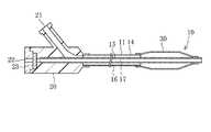
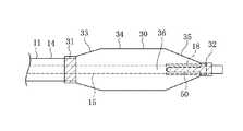
まず、バルーンカテーテル10の構成について説明する。バルーンカテーテル10は、図1に示すように、長尺な中空状のカテーテル本体部11と、カテーテル本体部11の先端部に設けられるバルーン30と、カテーテル本体部11の基端に固着されたハブ20とを有している。 First, the configuration of the
カテーテル本体部11は、中空の管状体である外管14と、外管14の内部に配置される内管15とを備えている。外管14と内管15の間には、バルーン30を拡張するための拡張用流体が流通する拡張ルーメン16が形成され、内管15の内側にはガイドワイヤー(図示しない)が挿通されるガイドワイヤールーメン17が形成される。 The catheter
外管14および内管15は、ある程度の可撓性を有する材料により形成されるのが好ましく、そのような材料としては、例えば、ポリエチレン、ポリプロピレン、ポリブテン、エチレン−プロピレン共重合体、エチレン−酢酸ビニル共重合体、アイオノマー、あるいはこれら二種以上の混合物等のポリオレフィンや、軟質ポリ塩化ビニル樹脂、ポリアミド、ポリアミドエラストマー、ポリエステル、ポリエステルエラストマー、ポリウレタン、ポリテトラフルオロエチレン等のフッ素樹脂、シリコーンゴム、ラテックスゴム等が使用できる。 The
バルーン30は、外管14や内管15と同様に可撓性を有する材料により形成されている。バルーン30は、カテーテル本体部11の先端部を形成しているため、柔軟性の高い材料が選択される。なお、図1においてバルーン30は収縮した状態である。また、図面において軸方向に沿って切断した断面図では、バルーン30が収縮した状態と拡張した状態を、模式的に示している。 The
バルーン30の先端側は内管15に固着され、基端側は外管14に固着されていて、バルーン30内が拡張ルーメン16に連通している。これにより、拡張ルーメン16を介して拡張用流体を注入することで、バルーン30を拡張させることができる。拡張用流体は気体でも液体でもよく、例えばヘリウムガス、CO2ガス、O2ガス等の気体や、生理食塩水、造影剤等の液体を用いることができる。The distal end side of the
ハブ20は、外管14と内管15の間に形成される拡張ルーメン16と連通して拡張用流体を流入出させるポートとして機能する第1開口部21と、ガイドワイヤールーメン17と連通する第2開口部22とを備えている。第2開口部22には、ガイドワイヤーを挿通自在としつつ血液の流出を抑制する止血弁23が設けられる。 The
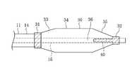
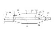
次に、バルーン30の構造について詳細に説明する。図2に示すように、バルーン30の基端側端部は、外管14の周面に対して融着された基端側固着部31である。バルーン30は、基端側固着部31から先端側に向かって外径が大きくなる拡径部33と、拡径部33と連続しカテーテル本体部11の軸方向に略同径の同径部34と、同径部34と連続し先端側に向かって外径が小さくなる縮径部35とを有している。さらに、バルーン30の先端側端部は、内管15の周面に対して融着された先端側固着部32である。 Next, the structure of the
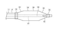
収縮時のバルーン30は、実際には以下に述べるような形状を有している。図3に示すように、収縮時のバルーン30は、内管15の周囲に折り畳まれた状態となっている。折り畳まれたバルーン30は、内管15の周方向に沿い、内管15と接触する接触部36と、接触部36から径方向に突出する羽根部37とを有している。接触部36は、内管15の周面に密着している。また、羽根部37は、接触部36から径方向外方に向かうと共に、周方向に向かって湾曲するように伸びている。バルーン30が折り畳まれた状態において、羽根部37は周方向に3箇所形成され、各羽根部37の間を形成する接触部36も周方向に3箇所形成される。なお、3つの羽根部37は、いずれも周方向において同じ向きに湾曲している。 The deflated
バルーン30の縮径部35は、内管15の周面と連結される連結部40を有している。連結部40は、周方向3箇所の接触部36が、それぞれ内管15と連結されることにより形成されている。図3では連結部40を分かりやすいように太線で示している。本例では、連結部40はバルーン30と内管15との融着により形成されている。 The reduced
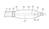
図4では、バルーン30がカテーテル本体部11と融着される領域をハッチングで表している。この図のように、バルーン30は、基端側固着部31において、周方向に外管14と融着され、先端側固着部32において、周方向に内管15と融着されている。これに加えて、バルーン30の縮径部35は、周方向において接触部36となる領域が内管15と融着され、連結部40を形成している。 In FIG. 4, the region where the
本例において連結部40は、先端側固着部32から基端側に向かって連続した線状に形成され、その端部は縮径部35の基端側端部まで伸びている。また、連結部40の基端側端部は、滑らかな曲線状、具体的には略半円形状を有するように形成されている。 In this example, the connecting
このように連結部40を有するバルーン30は、拡張用流体を送り込み加圧すると拡張し、図5に示すような形状となる。縮径部35の部分において、接触部36は、連結部40により内管15に固着されているので、内管15と密着したままである。一方、羽根部37であった部分は、内部に拡張用流体が充填されることで膨張する。また、同径部34は、断面略円形状に拡張し、連結部40による変形は最小限に止められる。 As described above, the
バルーン30は、図5の加圧状態から減圧すると収縮し、再び図3の収縮状態に戻る。このとき、縮径部35の接触部36は、連結部40により内管15と密着しているので、バルーン30の縮径部35よりも基端側の部分についても、周方向3箇所の接触部36が元の形状に戻りやすくなる。これに伴い、周方向3箇所の羽根部37も、元の形状に戻りやすくなる。バルーン30が拡張と収縮を複数回繰り返した場合であっても、縮径部35の接触部36が、内管15と常に密着しているため、確実に元の形状に戻ることができる。すなわち、バルーン30のリラップ性を良好にすることができる。 When the
本例では、連結部40は基端側の端部が、縮径部35の基端側端部まで伸びているので、連結部40によりバルーン30のうち同径部34よりも基端側の部分について、収縮時の元の形状に戻す効果を大きくすることができる。 In this example, since the end of the connecting
また、連結部40の基端側の端部が、滑らかな曲線状に形成されていることにより、バルーン30が加圧されて拡張した際に、連結部40の基端側の端部に応力が集中しないようにして、連結部40が破断することを防止できる。 Further, since the proximal end portion of the connecting
連結部40の態様は、図4に示した例には限られない。次に、第1変形例の連結部41について説明する。図6に示すように、第1変形例の連結部41は、バルーン30の縮径部35だけでなく、拡径部33にも形成されている。縮径部35側の連結部41は、図4の連結部40と同じ構成である。拡径部33側の連結部41は、周方向においては、バルーン30の接触部36の領域に形成され、軸方向においては、基端側固着部31から先端側に向かって線状に伸びており、先端側の端部は拡径部33の先端側端部まで伸びている。 The mode of the connecting
このように、縮径部35側だけでなく、拡径部33側にも連結部41を設けたことにより、バルーン30の収縮時により元の形状に戻りやすくすることができる。なお、第2変形例以下では、縮径部35にのみ連結部を設けた態様であるが、いずれの変形例についても、縮径部35側に加えて拡径部33側にも連結部を設けることができる。さらに、拡径部33側のみに連結部を設けてもよい。また、拡径部33側の連結部41は、バルーン30と内管15とを連結しているが、外管14をバルーン30の内部まで伸ばし、外管14とバルーン30とを連結するようにしてもよい。 As described above, by providing the connecting
次に、第2変形例の連結部42について説明する。図7に示すように、本例の連結部42は、周方向においては、バルーン30の接触部36の領域に形成され、軸方向においては、先端側固着部32から基端側に向かって線状に伸びており、基端側の端部は縮径部35の軸方向中間位置まで伸びている。すなわち、本例の連結部42は、図4の連結部40よりも軸方向に短い。 Next, the connecting
このように、連結部42の軸方向の長さは、任意に設定することができる。連結部42の先端位置が、縮径部35において先端側に位置することで、バルーン30が収縮する際に元の形状に戻る力は弱くなるが、連結部42でバルーン30と内管15とが連結されていることによる、拡張時のバルーン形状の変形、特に同径部における形状が変形することを防ぐことができる。 In this way, the axial length of the connecting
次に、第3変形例と第4変形例の連結部について説明する。図8に示すように、第3変形例の連結部43は、軸方向において縮径部35の範囲に2箇所、点状に形成されている。連結部43の周方向の位置は、バルーン30の接触部36の領域である。このように、連結部43は連続した線状でなくてもよい。また、図9に示すように、連結部44が1箇所だけであってもよい。 Next, the connecting portions of the third modified example and the fourth modified example will be described. As shown in FIG. 8, the connecting
次に、第5変形例と第6変形例の連結部について説明する。図10に示すように、第5変形例の連結部45は、先端側固着部32から基端側に向かって伸び、連結部42の周方向の幅は、先端側から基端側に向かって次第に小さくなるように形成されており、連結部42全体としては略三角形状を有している。それ以外は、図4の連結部40と同様である。また、図11に示すように、第6変形例の連結部46は、先端側固着部32から基端側に向かって伸び、連結部46の周方向の幅は、先端側が大きく、基端側が小さく、軸方向中間位置で幅が変化するように形成されている。このように、連結部の形状は、様々に設定することが可能である。 Next, the connecting portions of the fifth modified example and the sixth modified example will be described. As shown in FIG. 10, the connecting
次に、第7変形例の連結部47について説明する。図12に示すように、本例の連結部47は、内管15とバルーン30とを懸架するように設けられている。連結部47は伸縮性を有する素材によって形成されている。また、連結部47は、周方向にはバルーン30の接触部36の範囲に、軸方向にはバルーン30の縮径部35の範囲に、形成されている。 Next, the connecting
図12はバルーン30が拡張した状態であり、バルーン30が拡張すると、伸縮性を有する連結部47は、バルーン30と共に伸張する。伸張に対し、連結部47は収縮する方向に反発力を発生するが、この反発力がバルーン30拡張時の同径部34の形状に大きな影響を与えない程度に、連結部47を形成する必要がある。バルーン30の収縮時には、連結部47による収縮方向への付勢力で、接触部36を元の形状に確実に戻すことができる。伸縮性を有する連結部47の材料としては、例えばゴムや熱可塑性エラストマーなどを使用することができる。 FIG. 12 shows a state in which the
このように、バルーン30とカテーテル本体部11とを直接固定するだけでなく、伸縮性を有する材料で連結部47を形成しても、同様の効果を得ることができる。また、この場合、連結部47の弾性を適切に設定することで、軸方向において縮径部35や拡径部33だけでなく、同径部34の範囲にも設けることができる。また、伸縮性を有する材料で形成された連結部47の形状及び配置は、バルーン30とカテーテル本体部11とを直接固定した図4及び図6〜11の例のように構成してもよい。 As described above, the same effect can be obtained not only by directly fixing the
次に、第8変形例と第9変形例の連結部について説明する。第8変形例では、図13に示すように、内管15に外周部材18が設けられている。外周部材18は、内管15よりも一回り大きい径を有した管状に形成されている。外周部材18の先端側端部は、バルーン30の先端側固着部32と共に内管15に対して融着されている。一方、外周部材18は、先端側端部以外の部分は、内管15の周面には拘束されていない。 Next, the connecting portions of the eighth modified example and the ninth modified example will be described. In the eighth modified example, as shown in FIG. 13, an outer
本例において連結部50は、バルーン30と外周部材18との間を連結している。連結部50は、バルーン30の先端側固着部32よりも基端側に向かって伸びているので、外周部材18の連結部50と連結される部分は、内管15の周面に拘束されていない。このため、バルーン50が拡張した際に、外周部材18は径方向外側に引っ張られるが、内管15はバルーン50に引っ張られることがないようにすることができる。 In this example, the connecting
内管15が径方向外側に引っ張られると、内管15が延伸する。これにより、内管15の肉厚が薄くなるために、これが圧潰されやすくなり、ガイドワイヤーの摺動性を悪化させる可能性がある。内管15の外側に外周部材18が設けられ、外周部材18とバルーン30の間を連結部50で連結することにより、このような問題を解消することができる。 When the
第9変形例は、図14に示すように、連結部51が点状に形成されており、外周部材19は、軸方向において連結部51が形成される範囲を含む短尺管状に形成されている。この場合、外周部材19は内管15とは融着などされておらず、内管15の周面に拘束されていない。このように、連結部51が軸方向に短い場合に、それに対応する部分にのみ外周部材19を設けることで、内管15の径方向への拡大を最低限に抑えることができる。なお、外周部材の形状は、管状には限られず、内管15の外周の少なくとも一部に存在する形状であればよい。 In the ninth modification, as shown in FIG. 14, the connecting
次に、第10変形例と第11変形例の連結部について説明する。第10変形例では、図15に示すように、内管15の一部が、他の部分よりも強度を大きくした補強部15aとされている。この補強部15aとバルーン30とが連結されることで、連結部52が形成される。内管15は、軸方向において連結部52が形成される範囲に補強部15aを有している。 Next, the connecting portions of the tenth modification and the eleventh modification will be described. In the tenth modification, as shown in FIG. 15, a part of the
補強部15aは、内管15の製造時にその部分の肉厚を大きくすることにより形成することができる。また、均一な肉厚の内管15を製造しておき、その上から管状の別部材で内管15の一部を被覆し、融着や接着などにより両者を一体化させて補強部15aを形成してもよい。 The reinforcing
また、第11変形例では、図16に示すように、連結部53が点状に形成されており、この連結部53に対応した部分にのみ、補強部15bを形成している。 Further, in the eleventh modified example, as shown in FIG. 16, the connecting
このように、内管15に補強部を設けることによっても、バルーン30が拡張して、内管15が連結部により径方向外側に引っ張られた場合に、内管の延伸を抑制することができる。 In this way, by providing the reinforcing portion on the
以上のように、本実施形態に係るバルーンカテーテル10は、長尺なカテーテル本体部11と、カテーテル本体部11の先端側に設けられる拡縮可能なバルーン30と、を有し、カテーテル本体部11は中空状の外管14及び該外管の内側に配置される中空状の内管15を有し、バルーン30は収縮状態で、内管15と接触する接触部36と、接触部36から径方向に突出する羽根部37とを有するように折り畳まれ、バルーン30は、接触部36にカテーテル本体部11と連結される連結部40を有する。このため、バルーン30が拡張と収縮を複数回繰り返した場合であっても、接触部36が連結部40により内管15と連結されているため、収縮時には確実に元の形状に戻ることができる。すなわち、バルーン30の外側から外部部材を装着しなくても、バルーン30のリラップ性を良好にすることができる。 As described above, the
また、カテーテル本体部11は、バルーン30は、基端側が外管14に固定され、先端側が内管15に固定され、連結部40は、外管14または内管15の周面に対して固着されて形成されるようにすれば、バルーン30を外管14または内管15の周面に固着させるだけで連結部40を形成することができ、製造を容易にすることができる。 In the
また、バルーン30は、基端側から先端側に向かって径が大きくなる拡径部33と、拡径部33と連続し軸方向に沿って略同一径の同径部34と、同径部34と連続し基端側から先端側に向かって径が小さくなる縮径部35とを有し、連結部40は、同径部34に存在しないようにすれば、治療時の有効部分である同径部34の形状に、連結部40による影響をできるだけ与えないようにすることができる。 In addition, the
また、連結部40は、バルーン30が外管14または内管15と固定された固着部31,32からバルーン30の中央側に向かって、バルーン30と内管15とが線状に固着されて形成されるようにすれば、連結部40によるバルーン30と内管15との連結強度を大きくでき、バルーン30の拡張時に連結部40が剥離(破断)することを防止できる。 In addition, in the connecting
また、連結部42は、バルーン30が外管14または内管15と固定された固着部31,32よりバルーン30の中央側の位置に、バルーン30と内管15とが点状に固着されて形成されるようにすれば、固着面積が小さくてよいので、製造を容易にすることができる。 Further, in the connecting
また、連結部40は、バルーン30の中央側の端部が滑らかな曲線状に形成されるようにすれば、バルーン30が拡張した際に、連結部40の中央側の端部に応力が集中しないようにすることができ,連結部40の剥離(破断)を防止できる。 Further, in the connecting
また、カテーテル本体部11は、中空状の外管14及び該外管14の内側に配置される中空状の内管15を有し、バルーン30は、基端側が外管14に固定され、先端側が内管15に固定され、連結部47は、バルーン30と外管14または内管15との間を懸架する伸縮性の材料によって形成されるようにすれば、連結部47の弾性を適切に設定することで、同径部34を含むバルーン30の広範囲に連結部47を設けることができる。 The
また、内管15は、バルーン30の内部における外周の少なくとも一部に外周部材18を有し、連結部50は、バルーン30と外周部材18とを連結し、外周部材18は、軸方向において少なくとも連結部50が連結される範囲では、内管15の周面に拘束されないようにすれば、バルーン30が拡張した際に、連結部50により内管15が外方に引っ張られないようにすることができ、内管15が延伸することによるガイドワイヤーの摺動性悪化を防止できる。 Further, the
また、内管15は、軸方向において少なくとも連結部52により連結される範囲に、強度を大きくした補強部15aを有するようにすれば、バルーン30が拡張した際に、連結部52により内管15が外方に引っ張られても、その部分の強度が低下することに伴うガイドワイヤーの摺動性悪化を防止できる。 In addition, if the
また、上述の実施形態に係るバルーンカテーテルは、オーバーザワイヤ型(Over−the−wire type)であるが、ラピッドエクスチェンジ型(Rapid exchange type)であってもよい。 Further, although the balloon catheter according to the above-described embodiment is an over-the-wire type, it may be a rapid exchange type.
また、上記の実施形態に係る発明の構成は好適な実施例として挙げたものであり、本発明の実施形態はこれに限定されない。つまり、本発明と同様の効果を奏する範囲において、種々の変更をすることができる。例えば連結部について、基端側の端部の形状が滑らかな曲線状となっていることを例として挙げたが、三角でも四角等の形状でもよい。 The configuration of the invention according to the above-described embodiment is given as a preferred example, and the embodiment of the present invention is not limited to this. That is, various modifications can be made within the range of achieving the same effects as the present invention. For example, regarding the connecting portion, the shape of the end portion on the base end side has a smooth curved shape, but the shape may be triangular or square.
本出願は、2015年1月26日に出願された日本特許出願番号2015−12236号に基づいており、それらの開示内容は、参照され、全体として、組み入れられている。 This application is based on Japanese Patent Application No. 2015-12236 filed on Jan. 26, 2015, the disclosures of which are incorporated by reference in their entirety.
10 バルーンカテーテル、
11 カテーテル本体部、
14 外管、
15 内管、
16 拡張ルーメン、
17 ガイドワイヤールーメン、
20 ハブ、
21 第1開口部、
22 第2開口部、
23 止血弁、
30 バルーン、
31 基端側固着部、
32 先端側固着部、
33 拡径部、
34 同径部、
35 縮径部、
36 接触部、
37 羽根部、
40 連結部。10 balloon catheter,
11 catheter body,
14 outer tube,
15 inner pipe,
16 extended lumens,
17 guide wire lumen,
20 hubs,
21 first opening,
22 second opening,
23 Hemostasis valve,
30 balloons,
31 Base side fixed part,
32 Tip side fixed part,
33 Expanded part,
34 Same diameter part,
35 reduced diameter part,
36 contact part,
37 blades,
40 connection.
Claims (8)
Translated fromJapanese前記カテーテル本体部の先端側に設けられる拡縮可能なバルーンと、を有し、
前記カテーテル本体部は中空状の外管及び該外管の内側に配置される中空状の内管を有し、前記バルーンは収縮状態で、前記内管と接触する接触部と、該接触部から径方向に突出する羽根部とを有するように折り畳まれ、
前記バルーンは、前記接触部に前記カテーテル本体部と連結される連結部を有し、
前記バルーンは、前記外管の周面に固着された基端側固着部と、該基端側固着部から先端側に向かって径が大きくなる拡径部と、該拡径部と連続し軸方向に沿って略同一径の同径部と、該同径部と連続し基端側から先端側に向かって径が小さくなる縮径部と、該縮径部の先端側で前記内管の周面に対して固着された先端側固着部と、を有し、
前記連結部は、前記同径部には存在せず、前記縮径部及び/または前記拡径部の内表面が前記カテーテル本体部の内管と連結されることで形成されるバルーンカテーテル。A long catheter body,
A balloon provided on the distal end side of the catheter body,
The catheter body has a hollow outer tube and a hollow inner tube disposed inside the outer tube, and the balloon is in a deflated state, a contact portion that contacts the inner tube, and a contact portion from the contact portion. Folded to have a blade portion protruding in the radial direction,
The balloon has a connecting portion connected to the catheter body at the contact portion,
The balloon includesa proximal end side fixed portion fixed to the peripheral surface of the outer tube, an enlarged diameter portion whose diameter increases from the proximalend side fixed portion toward the distalend side , and a shaft continuous with the enlarged diameter portion. The same diameter portion having substantially the same diameter along the direction, the reduced diameter portion that is continuous with the same diameter portion and decreases in diameter from the base end side towardthe distal end side, and the inner pipe on the distal end side of the reduced diameter portion. A front end side fixing portion fixed to the peripheral surface ,
The balloon catheter, wherein the connecting portiondoes not exist in the same diameter portion, and isformed by connecting the inner surface of the reduced diameter portion and/or the enlarged diameter portion to the inner tube of the catheter body portion .
Applications Claiming Priority (3)
| Application Number | Priority Date | Filing Date | Title |
|---|---|---|---|
| JP2015012236 | 2015-01-26 | ||
| JP2015012236 | 2015-01-26 | ||
| PCT/JP2015/084749WO2016121244A1 (en) | 2015-01-26 | 2015-12-11 | Balloon catheter |
Publications (2)
| Publication Number | Publication Date |
|---|---|
| JPWO2016121244A1 JPWO2016121244A1 (en) | 2017-11-02 |
| JP6749847B2true JP6749847B2 (en) | 2020-09-02 |
Family
ID=56542878
Family Applications (1)
| Application Number | Title | Priority Date | Filing Date |
|---|---|---|---|
| JP2016571804AActiveJP6749847B2 (en) | 2015-01-26 | 2015-12-11 | Balloon catheter |
Country Status (3)
| Country | Link |
|---|---|
| US (1) | US10617856B2 (en) |
| JP (1) | JP6749847B2 (en) |
| WO (1) | WO2016121244A1 (en) |
Families Citing this family (4)
| Publication number | Priority date | Publication date | Assignee | Title |
|---|---|---|---|---|
| US20190150963A1 (en)* | 2016-05-18 | 2019-05-23 | Montefiore Medical Center | Devices and methods for respiratory airways bleeding management and temporary occlusion of airways |
| CN114025824B (en)* | 2019-06-24 | 2024-10-15 | 业聚医疗私人有限公司 | Balloon-anchored guide catheter extension |
| GB2601761A (en)* | 2020-12-08 | 2022-06-15 | Ridgeback Tech Ltd | Balloon catheters |
| WO2024035779A1 (en)* | 2022-08-12 | 2024-02-15 | Boston Scientific Scimed, Inc. | Segmented medical balloon |
Family Cites Families (13)
| Publication number | Priority date | Publication date | Assignee | Title |
|---|---|---|---|---|
| US5087246A (en)* | 1988-12-29 | 1992-02-11 | C. R. Bard, Inc. | Dilation catheter with fluted balloon |
| US4941877A (en)* | 1989-01-26 | 1990-07-17 | Cordis Corporation | Balloon catheter |
| US5147302A (en)* | 1989-04-21 | 1992-09-15 | Scimed Life Systems, Inc. | Method of shaping a balloon of a balloon catheter |
| US5226887A (en) | 1992-02-07 | 1993-07-13 | Interventional Technologies, Inc. | Collapsible folding angioplasty balloon |
| US5383856A (en)* | 1993-03-19 | 1995-01-24 | Bersin; Robert M. | Helical spiral balloon catheter |
| US5840064A (en)* | 1994-03-31 | 1998-11-24 | United States Surgical Corporation | Method and apparatus for treating stenosis or other constriction in a bodily conduit |
| US5792172A (en)* | 1996-12-23 | 1998-08-11 | Isostent, Inc. | Multifold balloon for stent deployment |
| US6544224B1 (en)* | 2000-05-05 | 2003-04-08 | Advanced Cardiovascular Systems, Inc. | Lobed balloon catheter and method of use |
| US6425882B1 (en) | 2001-05-01 | 2002-07-30 | Interventional Technologies Inc. | Folding spring for a catheter balloon |
| US7744620B2 (en)* | 2003-07-18 | 2010-06-29 | Intervalve, Inc. | Valvuloplasty catheter |
| US7887557B2 (en)* | 2003-08-14 | 2011-02-15 | Boston Scientific Scimed, Inc. | Catheter having a cutting balloon including multiple cavities or multiple channels |
| US7857786B2 (en)* | 2006-11-03 | 2010-12-28 | Cook Incorporated | Balloon catheter having improved balloon folding capability |
| US9895517B2 (en)* | 2011-01-18 | 2018-02-20 | Loma Vista Medical, Inc. | Inflatable medical devices |
- 2015
- 2015-12-11JPJP2016571804Apatent/JP6749847B2/enactiveActive
- 2015-12-11WOPCT/JP2015/084749patent/WO2016121244A1/ennot_activeCeased
- 2017
- 2017-07-18USUS15/653,078patent/US10617856B2/enactiveActive
Also Published As
| Publication number | Publication date |
|---|---|
| US20170312487A1 (en) | 2017-11-02 |
| WO2016121244A1 (en) | 2016-08-04 |
| US10617856B2 (en) | 2020-04-14 |
| JPWO2016121244A1 (en) | 2017-11-02 |
Similar Documents
| Publication | Publication Date | Title |
|---|---|---|
| US12178976B2 (en) | Reinforced balloon catheter | |
| JP6205550B2 (en) | Balloon catheter | |
| EP3795199B1 (en) | Balloon catheter | |
| JP6442229B2 (en) | Balloon catheter | |
| JP6348486B2 (en) | Balloon catheter and method for manufacturing balloon catheter | |
| JP6749847B2 (en) | Balloon catheter | |
| WO2016163495A1 (en) | Balloon catheter | |
| JP2015104671A (en) | Medical balloon | |
| CN115591087A (en) | Inflatable infusion balloon with external mesh and related methods | |
| US20220088354A1 (en) | Balloon catheter | |
| KR102736802B1 (en) | BALLOON CATHETER | |
| JP6682726B2 (en) | Balloon catheter for vascular occlusion | |
| JP6048415B2 (en) | Atherectomy catheter | |
| JP5759736B2 (en) | Balloon catheter | |
| JP2011152181A (en) | Balloon catheter | |
| JPH0889588A (en) | Catheter | |
| JP6449029B2 (en) | Balloon catheter | |
| WO2013122003A1 (en) | Balloon for vascular occlusion balloon catheter, vascular occlusion balloon catheter, and production method for balloon for vascular occlusion balloon catheter | |
| CN112601570A (en) | Inflatable medical balloon with S-shaped fibers | |
| JP2009056297A (en) | Balloon catheter | |
| JP2018149082A (en) | Medical long body | |
| JP2024169212A (en) | Balloon catheter | |
| JP2019050861A (en) | Baloon catheter, and manufacturing method thereof | |
| JP6205549B2 (en) | Balloon catheter | |
| JP7465696B2 (en) | Balloon catheter |
Legal Events
| Date | Code | Title | Description |
|---|---|---|---|
| A621 | Written request for application examination | Free format text:JAPANESE INTERMEDIATE CODE: A621 Effective date:20181010 | |
| A131 | Notification of reasons for refusal | Free format text:JAPANESE INTERMEDIATE CODE: A131 Effective date:20190805 | |
| A601 | Written request for extension of time | Free format text:JAPANESE INTERMEDIATE CODE: A601 Effective date:20191003 | |
| A521 | Request for written amendment filed | Free format text:JAPANESE INTERMEDIATE CODE: A523 Effective date:20191024 | |
| A131 | Notification of reasons for refusal | Free format text:JAPANESE INTERMEDIATE CODE: A131 Effective date:20200316 | |
| A521 | Request for written amendment filed | Free format text:JAPANESE INTERMEDIATE CODE: A523 Effective date:20200511 | |
| TRDD | Decision of grant or rejection written | ||
| A01 | Written decision to grant a patent or to grant a registration (utility model) | Free format text:JAPANESE INTERMEDIATE CODE: A01 Effective date:20200803 | |
| A61 | First payment of annual fees (during grant procedure) | Free format text:JAPANESE INTERMEDIATE CODE: A61 Effective date:20200812 | |
| R150 | Certificate of patent or registration of utility model | Ref document number:6749847 Country of ref document:JP Free format text:JAPANESE INTERMEDIATE CODE: R150 | |
| R250 | Receipt of annual fees | Free format text:JAPANESE INTERMEDIATE CODE: R250 | |
| R250 | Receipt of annual fees | Free format text:JAPANESE INTERMEDIATE CODE: R250 |