JP6749108B2 - Method and system for controlled heat treatment of human surface texture - Google Patents
Method and system for controlled heat treatment of human surface textureDownload PDFInfo
- Publication number
- JP6749108B2 JP6749108B2JP2016040640AJP2016040640AJP6749108B2JP 6749108 B2JP6749108 B2JP 6749108B2JP 2016040640 AJP2016040640 AJP 2016040640AJP 2016040640 AJP2016040640 AJP 2016040640AJP 6749108 B2JP6749108 B2JP 6749108B2
- Authority
- JP
- Japan
- Prior art keywords
- probe
- concave spherical
- treatment system
- transducer
- interest
- Prior art date
- Legal status (The legal status is an assumption and is not a legal conclusion. Google has not performed a legal analysis and makes no representation as to the accuracy of the status listed.)
- Expired - Lifetime
Links
Images


Classifications
- A—HUMAN NECESSITIES
- A61—MEDICAL OR VETERINARY SCIENCE; HYGIENE
- A61B—DIAGNOSIS; SURGERY; IDENTIFICATION
- A61B8/00—Diagnosis using ultrasonic, sonic or infrasonic waves
- A61B8/54—Control of the diagnostic device
- A61B8/546—Control of the diagnostic device involving monitoring or regulation of device temperature
- A—HUMAN NECESSITIES
- A61—MEDICAL OR VETERINARY SCIENCE; HYGIENE
- A61N—ELECTROTHERAPY; MAGNETOTHERAPY; RADIATION THERAPY; ULTRASOUND THERAPY
- A61N7/00—Ultrasound therapy
- A61N7/02—Localised ultrasound hyperthermia
- A—HUMAN NECESSITIES
- A61—MEDICAL OR VETERINARY SCIENCE; HYGIENE
- A61B—DIAGNOSIS; SURGERY; IDENTIFICATION
- A61B8/00—Diagnosis using ultrasonic, sonic or infrasonic waves
- A61B8/08—Clinical applications
- A—HUMAN NECESSITIES
- A61—MEDICAL OR VETERINARY SCIENCE; HYGIENE
- A61B—DIAGNOSIS; SURGERY; IDENTIFICATION
- A61B8/00—Diagnosis using ultrasonic, sonic or infrasonic waves
- A61B8/44—Constructional features of the ultrasonic, sonic or infrasonic diagnostic device
- A61B8/4483—Constructional features of the ultrasonic, sonic or infrasonic diagnostic device characterised by features of the ultrasound transducer
- A—HUMAN NECESSITIES
- A61—MEDICAL OR VETERINARY SCIENCE; HYGIENE
- A61B—DIAGNOSIS; SURGERY; IDENTIFICATION
- A61B90/00—Instruments, implements or accessories specially adapted for surgery or diagnosis and not covered by any of the groups A61B1/00 - A61B50/00, e.g. for luxation treatment or for protecting wound edges
- A61B90/36—Image-producing devices or illumination devices not otherwise provided for
- A61B90/37—Surgical systems with images on a monitor during operation
- A61B2090/378—Surgical systems with images on a monitor during operation using ultrasound
- A—HUMAN NECESSITIES
- A61—MEDICAL OR VETERINARY SCIENCE; HYGIENE
- A61B—DIAGNOSIS; SURGERY; IDENTIFICATION
- A61B8/00—Diagnosis using ultrasonic, sonic or infrasonic waves
- A61B8/42—Details of probe positioning or probe attachment to the patient
- A61B8/4209—Details of probe positioning or probe attachment to the patient by using holders, e.g. positioning frames
- A—HUMAN NECESSITIES
- A61—MEDICAL OR VETERINARY SCIENCE; HYGIENE
- A61B—DIAGNOSIS; SURGERY; IDENTIFICATION
- A61B8/00—Diagnosis using ultrasonic, sonic or infrasonic waves
- A61B8/42—Details of probe positioning or probe attachment to the patient
- A61B8/4272—Details of probe positioning or probe attachment to the patient involving the acoustic interface between the transducer and the tissue
- A61B8/4281—Details of probe positioning or probe attachment to the patient involving the acoustic interface between the transducer and the tissue characterised by sound-transmitting media or devices for coupling the transducer to the tissue
- A—HUMAN NECESSITIES
- A61—MEDICAL OR VETERINARY SCIENCE; HYGIENE
- A61N—ELECTROTHERAPY; MAGNETOTHERAPY; RADIATION THERAPY; ULTRASOUND THERAPY
- A61N7/00—Ultrasound therapy
- A61N2007/0078—Ultrasound therapy with multiple treatment transducers
Landscapes
- Health & Medical Sciences (AREA)
- Life Sciences & Earth Sciences (AREA)
- Animal Behavior & Ethology (AREA)
- Veterinary Medicine (AREA)
- Nuclear Medicine, Radiotherapy & Molecular Imaging (AREA)
- Public Health (AREA)
- Radiology & Medical Imaging (AREA)
- Engineering & Computer Science (AREA)
- Biomedical Technology (AREA)
- General Health & Medical Sciences (AREA)
- Pathology (AREA)
- Molecular Biology (AREA)
- Surgery (AREA)
- Medical Informatics (AREA)
- Heart & Thoracic Surgery (AREA)
- Physics & Mathematics (AREA)
- Biophysics (AREA)
- Gynecology & Obstetrics (AREA)
- Surgical Instruments (AREA)
- Thermotherapy And Cooling Therapy Devices (AREA)
- Ultra Sonic Daignosis Equipment (AREA)
- Radiation-Therapy Devices (AREA)
Description
Translated fromJapanese本発明は概して治療処置システム、さらに詳しくはヒト表面組織における制御された熱傷に対する方法およびシステムに関する。 The present invention relates generally to therapeutic treatment systems, and more particularly to methods and systems for controlled burns in human surface tissue.
美容適用のためのヒト表面組織の治療処置の現在の技術は、いくつかの異なるエネルギー源を活用する。典型的な従来のエネルギー源には、剥離および非剥離レーザー、無線周波(RF)エネルギー、そしてさらに最近では超音波を利用した技術が含まれる。超音波を利用した治療法の現在の例には、Kloptek(特許文献1およびその関連継続、特許文献2)、Hissongら(特許文献3)、およびColeman(特許文献4)において開示されているものがある。 Current techniques for therapeutic treatment of human surface tissue for cosmetic applications utilize several different energy sources. Typical conventional energy sources include ablative and non-ablative lasers, radio frequency (RF) energy, and more recently ultrasonic based techniques. Current examples of ultrasound-based therapies are those disclosed in Kloptek (US Pat. No. 5,093,849 and related references, US Pat. No. 5,037,049), Hisong et al. There is.
Kloptekは特許文献1において、「従来の温熱治療よりも有意に低い用量」を使用することによって外部表皮に有害な損傷を与えずに真皮層が「徐々に刺激されまたは炎症を起こす」ように集束超音波ビームを適用することによって皮膚の皺を軽減する方法を冒頭で示唆している。焦点強度500〜1500W/cm2でわずか10ns〜200μsの時間、つまり5μJ/cm2〜0.3ジュール/cm2でエネルギーが適用されるため、開示されている方法論は非熱傷を主張するのみである。このような低量のエネルギーにもかかわらず、穏やかな刺激および炎症とは対照的に傷害を引き起こすのに十分な47〜75℃まで組織温が上昇するとKloptekは主張している。その後Kloptekは特許文献2においてパルス状(連続波とは対照的に)超音波の使用を開示しているが、同じ低い焦点強度(500−1500W/cm2)とパルス幅(10ns−200μs)であり、そのような音響励振が真皮層において音響衝撃波およびキャビテーション効果を生じさせると主張している。実際は、組織の熱容量の本質的な限界、例えば皮膚の特定熱容量は約3430J/kg/Kであり、また音波の波及効果のため、特許文献1および特許文献2の特許においてまとめて教示されているように、そのような「徐々の刺激および炎症」で組織においてそのようなキャビテーション、温度上昇または衝撃波を誘発することはその技術に精通している者にとって技術的には不可能ではないにしても極めて難しい。Kloptek, in US Pat. No. 6,968,085, focused on “gradually irritating or inflamming” the dermal layer without damaging the outer epidermis by using “significantly lower doses than conventional hyperthermia” At the beginning, a method of reducing wrinkles on the skin by applying an ultrasonic beam is suggested. Since the energy is applied at a focal intensity of 500-1500 W/cm2 for a time of only 10 ns-200 μs,
Hissongは、剥離のステップが「皮膚の外部表面下50〜100μmに位置する開始縁から開始」し、「50〜100μmの深度」の損傷、つまり皮膚の表面より50μmから250μmの深度から広がっている損傷を生じさせるための局所性損傷の形成を含む、0.5〜12MHzからの周波数での皮膚再生方法を開示している。Hissongはまた、「2〜60秒間」の皮膚の加熱が局所的損傷を形成すると主張している。しかしながら、多数の欠点がHissongの技術の実用性を制限している。 Hissong states that the step of exfoliation "starts from a starting edge located 50-100 μm below the outer surface of the skin" and extends from "50-100 μm depth" of damage, ie from 50 μm to 250 μm depth from the surface of the skin. Disclosed is a method of skin renewal at frequencies from 0.5-12 MHz, including the formation of localized lesions to cause lesions. Hissong also claims that heating the skin for "2 to 60 seconds" creates localized damage. However, a number of drawbacks limit the practicality of Hisong's technology.
例えば、そのような長時間のエネルギー送出は結果として、横方向および軸方向の両方で有意な熱拡散および損傷の成長を引き起こし、浅い50μmから250μmの深度に渡って局所性損傷の配置を大幅に妨げる。第二に、Hissongの最高周波数、つまり12MHzが出願において考慮されていたとしたら、相当する組織における波長は約128μmとなるであろう。音響ビームプロファイルに対する焦点深度、つまり焦点ビームの長さがいくつかの波長から成ることを考慮すると、最もしっかりした回折限界的集束に対してさえも、熱的に誘導された損傷である長さ50から150μmというそのような短/サブ波長を生じさせることは実用的ではない。さらに、より低い周波数では、熱的に誘導された損傷であるそのような短/サブ波長を生じさせることはより難しいであろう。なお、強力な集束の使用は比較的大きな開口変換器を必要とするため、Hissongによって教示された多要素塗布器は非常に大きくなって顔面皮膚および頸部組織上を音響的に結合することは難しくなり、主張されているように損傷を融合させることは極めて難しいだろう。最後に、Hissongによって開示されているような、そのように浅い深度および長期処置回数に限定された損傷は、実用性および臨床処理能力の範囲に限界があり、このことは長期に渡ってミクロンレベルに固定された携帯プローブの維持という要件によってさらに妨げられる。 For example, such long-term energy delivery results in significant thermal diffusion and damage growth both laterally and axially, significantly locating localized damage over a shallow depth of 50 μm to 250 μm. Interfere. Second, if the highest Hisong frequency, 12 MHz, was considered in the application, the wavelength in the corresponding tissue would be about 128 μm. Considering that the depth of focus for an acoustic beam profile, ie the length of the focus beam consists of several wavelengths, even for the most robust diffraction-limited focusing, there is a length 50 that is a thermally induced damage. It is not practical to generate such short/sub-wavelengths from 1 to 150 μm. Moreover, at lower frequencies, it would be more difficult to produce such short/sub-wavelengths that are thermally induced damage. It should be noted that the use of strong focusing requires a relatively large aperture transducer, so the multi-element applicator taught by Hisong can be very large to acoustically couple on facial skin and neck tissue. It will be difficult and it will be extremely difficult to fuse the damage as claimed. Finally, such shallow depth and long-term treatment-limited injuries, as disclosed by Hissong, have a limited range of practicality and clinical throughput, which has led to long-term micron-level damage. Further hindered by the requirement of maintaining a portable probe fixed to the.
Colemanは、集束超音波剥離は活性表面で機械的に組み合わされて「配列した要素を放出する複数の個別超音波」を有する多要素単位を形成する別々の単一要素より開始し、「超音波エネルギーを放出し、放出された超音波エネルギーを、超音波放出部材からの所定の距離に集束させること」を提示したと主張している。Colemanは「配列に取り囲まれた要素を放出する複数の個別超音波」とさらに教示し、「互いに分離され明確に分かれ、同じ固定された所定の距離で外側に位置している各集束帯」で設定した。最後に、Colemanは「超音波エネルギーを放出するために選択的かつ独立して作動可能であり、および超音波エネルギーを放出しないために選択的かつ独立して作業可能でない前述の配列にある超音波放出要素」による組織内の損傷の形成を説明している。 Coleman says that focused ultrasonic ablation begins with separate single elements that are mechanically combined at the active surface to form a multi-element unit with "multiple individual ultrasonic waves emitting arrayed elements". Radiating energy and focusing the emitted ultrasonic energy at a predetermined distance from the ultrasonic emitting member. Coleman further teaches, "multiple individual ultrasound waves emitting elements surrounded by an array," in "each focusing band separated from one another and clearly separated and located at the same fixed predetermined distance". Set. Finally, Coleman states, "Ultrasound in the aforementioned arrangement that is selectively and independently actuatable to emit ultrasonic energy and not selectively and independently operable to not emit ultrasonic energy. The formation of lesions in tissue by the "releasing element" is described.
よって、Colemanは損傷形成案において柔軟性に対する本当の必要性を認識し、別々に作動された多要素変換器配列に共に格納された固定集束単一要素から、別々の損傷を組み合わせることによって様々な形態の損傷を生じさせようとしていると思われる。残念ながらそのような技術は熱膨張への多大な依存のため、空間的および時間的、そしてその精度においても大きく限られている。また、多要素配列は広い面積に及ぶよう構成されており、対象組織はほとんどの場合湾曲しているため、Colemanによって教示された集束超音波剥離装置を音響的に結合することは難しいであろう。さらに、良好な強度を得るために集束皿状変換器要素、または少なくとも平面ディスクが大きくなければならず、良好な集束、つまり高強度の獲得、低副ローブおよびグレーティングローブを達成するためにそのような要素を波長レベルで間隔を空ける必要があるため、配列が操作にとって煩わしくなる。最後に、Colemanは平面的な損傷を形成しようとしているが、そのような損傷はエネルギーの側方熱拡散を通して形成されるため、その損傷は縦方向にも制御不可能に成長する。 Thus, Coleman recognizes the real need for flexibility in lesion formation schemes, from fixed focusing single elements co-stored in separately actuated multi-element transducer arrays to varying degrees by combining different lesions. It is likely to cause morphological damage. Unfortunately, such techniques are greatly limited in space and time, and also in their accuracy, due to the large reliance on thermal expansion. Also, because the multi-element array is configured to span a large area and the target tissue is mostly curved, it may be difficult to acoustically couple the focused ultrasound ablation device taught by Coleman. .. Furthermore, in order to obtain good strength, the focusing dish-like transducer element, or at least the planar disc, must be large, such that in order to achieve good focusing, ie high strength acquisition, low side lobes and grating lobes. The array becomes cumbersome to operate because it is necessary to space the various elements at the wavelength level. Finally, Coleman seeks to form planar damage, but such damage also grows uncontrollably in the longitudinal direction because such damage is formed through lateral thermal diffusion of energy.
従って、従来の治療処置技術には、多数の基礎的物理制限、技術的困難、そしてヒト表面組織内の任意の形態、大きさ、深度の損傷の柔軟かつ正確な生成および制御を妨げる実用性問題がある。 Therefore, conventional therapeutic treatment techniques have many basic physical limitations, technical difficulties, and practical issues that prevent flexible and accurate generation and control of lesions of any morphology, size, and depth within human surface tissue. There is.
本発明の様々な側面によれば、ヒト表面組織における制御された熱傷に対する治療処置方法およびシステムは、音響エネルギー付与の精密な空間的および時間的制御を通して様々な形態、大きさ、および深度の熱損傷を制御可能に生じさせる能力に基づいている。典型的実施例によれば、典型的な治療処置システムは、処置計画、音響エネルギーの制御および/または送出、および/または関心領域に対する処置状況の監視を容易にすることができる制御システムおよびプローブシステムを含む。結果として、表面ヒト組織において熱傷の均一な(conformal)損傷を制御可能に生じさせる能力を実現することができる。 In accordance with various aspects of the present invention, methods and systems for the controlled treatment of controlled burns in human surface tissue provide various forms, sizes, and depths of heat through precise spatial and temporal control of acoustic energy delivery. It is based on the ability to controllably cause damage. According to an exemplary embodiment, an exemplary therapeutic treatment system is a control system and probe system that can facilitate treatment planning, control and/or delivery of acoustic energy, and/or monitoring of the treatment status for a region of interest. including. As a result, the ability to controllably produce conformal damage of burns in surface human tissue can be realized.
典型的実施例によれば、典型的な処置方法によって熱傷の領域が制御された均一な形態および大きさを構成することが可能となり、制御された空間的および時間的様式で組織の破壊(剥離)が可能となる。例えば、熱損傷は狭いまたは広い側方範囲、長いまたは短い軸長、および/または表面外部の組織までを含む深いまたは浅い位置で、適切かつ選択的に生成され得る。さらに、島状の別々の破壊を組織関心領域の一部または全体に生じさせることもでき、および/または隣接するまたは重なった構造を離れた損傷から生じさせることができる。本発明の他の典型的実施例によれば、典型的方法は隣接する熱傷を生成するための関心領域の一部または全体へのスキャニングを含むことができる。均一な損傷は変換器の構造および配置の選択などの変換器音響エネルギー空間分布の独立した選択および制御を通してだけでなく、駆動振幅レベル、周波数/波形の選択、および組織の熱剥離を制御するために調節および最適化ができるタイミング配列などの時間的制御を通しても達成することができる。また、音響結合インターフェースの温度を制御することができるため、さらに損傷形成制御の別の典型的方法が可能となる。
例えば、本願発明は以下の項目を提供する。
(項目1)
関心領域内のヒト表面組織における制御された熱傷のための治療処置システムであって、
該処置システムを制御するように構成された制御システムと、
該関心領域内に均一な損傷を生成するように構成されたプローブと、
を備え、該制御システムおよび該プローブは、該均一な損傷を生成するための空間的および時間的制御を行うように構成される、治療処置システム。
(項目2)
前記空間的制御は、変換器構成、距離、配置、方向および動作を含む1つ以上の空間的パラメータの操作制御を含む、項目1に記載の治療処置システム。
(項目3)
前記時間的制御は、駆動振幅レベル、周波数/波形、およびタイミング配列を含む1つ以上の時間的パラメータの操作制御を含む、項目1に記載の治療処置システム。
(項目4)
前記空間的および時間的制御は、開ループフィードバック制御ループを通して容易となる、項目1に記載の治療処置システム。
(項目5)
前記空間的および時間的制御は、閉ループフィードバック制御ループを通して容易となる、項目1に記載の治療処置システム。
(項目6)
前記制御システムは、
該制御システムおよび前記プローブにエネルギーを供給するように構成された電源コンポーネントと、
前記空間的および時間的パラメータを監視するように構成された感知および監視コンポーネントと、
表面ヒト組織接合部分および組織内へのさらなる深部において温度制御を容易にするように構成された冷却および結合制御と、
前記治療処置システムの全体制御に対する処理および制御論理コンポーネントと、
を備える、項目1に記載の治療処置システム。
(項目7)
前記プローブは、
前記制御システムと相互作用するための制御インターフェースと、
前記関心領域へ剥離超音波エネルギーを提供するように構成された変換器と、
該関心領域へ該変換器を音響的に結合させるための結合コンポーネントと、
該制御システムによる制御を容易にするための監視および感知コンポーネントと、
該プローブの手動および自動化動作のうちの1つを含む動作機構と、
を備える、項目1に記載の治療処置システム。
(項目8)
前記変換器構成は、集束、平面、非集束要素、1つ以上の単一要素、多要素および配列変換器、1つ以上の一次元、二次元、環状配列、直線、曲線、扇形、および球形配列による1つ以上の構造を備える、項目2に記載の治療処置システム。
(項目9)
前記変換器構成は、プラスチック、ポリウレタン、セラミック、金属、液体、および合成物のうち少なくとも1つから成る、1つ以上の球状レンズ、円柱状レンズ、電子的集束レンズ、凹面形レンズおよび薄型レンズを備える、項目8に記載の治療処置システム。
(項目10)
前記変換器構成は、1つ以上の周波数で励起される広帯域変換器を備える、項目2に記載の治療処置システム。
(項目11)
前記プローブは、センサ、動作センサ、スイッチ、作動装置、指示器、エンコーダ、プローブ識別、記憶装置、開口選択およびマルチプレクサ、電子整合ネットワーク、および切り替え、相互連結、接合具、取っ手、および使い捨て部材のうち少なくとも1つを備える、項目7に記載の治療処置システム。
(項目12)
前記制御システムは、処置計画、表示部、スイッチ、マイクロコントローラ、マイクロプロセッサ、コンピュータ、制御ファームウェア、ユーザーおよび制御ソフトウェアのうちの少なくとも1つを備える、項目6に記載の治療処置システム。
(項目13)
前記制御システムは、直流電力供給装置、電流センサ、電力検出および測定、波形合成装置、発振器、デジタルプログラム可能論理、増幅器/ドライバ、ビーム作成器、高調波フィルター、整合ネットワーク、冷却/音響結合/熱制御/音響集束制御ハードウェア、動作機構ドライバおよび制御、動作センサ、監視および閉ループ制御、インターフェーシングおよび制御、外部入力/出力ハードウェアおよび外部インターフェースのうちの1つ以上を備える、項目6に記載の治療処置システム。
(項目14)
前記プローブは、前記変換器と関心部との間の接合部分および関心領域間内への温度を調整するように構成された変換器音響結合、冷却、および/または液体充填音響レンズ効果機構を備える、項目6に記載の治療処置システム。
(項目15)
前記プローブは、組織接合部分に対して押し下げられ、それにより血液還流が少なくとも部分的に遮断され、組織が表面の処置関心領域において扁平になる、項目1に記載の治療処置システム。
(項目16)
前記制御された熱傷は、生物学的修復機構を引き起こすように継続的または不連続に沈着される、項目1に記載の治療処置システム。
(項目17)
前記の制御された熱傷は、前記表面ヒト組織の少なくとも1つの位置において、熱傷の形態および深度を変化させることにより、修復の最適化された周期を容易にするように沈着される、項目1に記載の治療処置システム。
(項目18)
前記変換器構成は、液体充填、ゲル充填、固体ゲルレンズ、ゴムまたは複合レンズ、または表面組織および/または音響結合媒体よりも低い速度および適切な電力処理能力を有する任意の材料のうちの少なくとも1つの外形の凸面形レンズを備える、項目2に記載の治療処置システム。
(項目19)
前記変換器構成は、単一変換要素内の映像化/治療複合変換器を備え、該映像化変換器は該治療変換器から電気的に分離される、項目2に記載の治療処置システム。
(項目20)
前記制御システムは、一次元、二次元、および三次元映像化または処置のうちの少なくとも1つを容易にするように構成された映像化システムを備える、項目1に記載の治療処置システム。
(項目21)
関心領域内のヒト表面組織における制御された熱傷のための方法であって、
様々な選択肢から熱損傷の少なくとも1つの形態、大きさ、および方向を選択するステップと、
制御システムおよびプローブに1つ以上の空間的パラメータを提供するステップと、
該制御システムおよび該プローブに1つ以上の時間的パラメータを提供するステップと、
該関心領域内の該熱損傷の該選択された形態、大きさ、および方向を生じさせるための該空間的パラメータおよび該時間的パラメータに基づき、該制御システムおよび該プローブの操作を制御するステップと、
を含む、方法。
(項目22)
前記制御操作は、前記熱損傷の前記選択された形態、大きさ、および方向を得た時を決定するために閉ループフィードバックループを活用するステップを備える、項目20に記載の方法。
(項目23)
前記制御操作は、前記熱損傷の前記選択された形態、大きさ、および方向を得た時を決定するために閉ループフィードバックループを活用するステップを備える、項目20に記載の方法。
(項目24)
前記空間的パラメータは、変換器構成、距離、配置、方向、および動作を含む、項目20に記載の方法。
(項目25)
前記時間的パラメータは、駆動振幅レベル、周波数/波形、およびタイミング配列を含む、項目20に記載の方法。
(項目26)
前記制御システムおよびプローブは、0〜30mmの可変深度および1〜40MHzの周波数範囲内で、組織の熱容量を越えるのに十分な時間およびエネルギーレベルによって熱損傷を生成するように制御される、項目20に記載の方法。
(項目27)
関心領域内の制御された熱傷に対して構成された処置システムであって、
該処置システムの空間的および時間的制御を容易にするように構成された制御システムと、
空間的および時間的制御のために構成された変換器を含むプローブであって、該プローブは、可変的形態、大きさ、および方向の均一な損傷を生成するように構成され、該損傷は、該関心領域に対する組織の熱容量を越えるのに十分な時間およびエネルギーレベルにおいて、1MHzと40MHzの間の周波数での該変換器の操作を通して、0と30mmの間の表面ヒト組織の深度内で構成されるプローブと、
を備える処置システム。
(項目28)
前記制御システムは、変換器構成、距離、配置、方向および動作を含む1つより多いの空間的パラメータの操作の制御、および駆動振幅レベル、周波数/波形、およびタイミング配列を含む1つより多いの時間的パラメータの操作の制御を行うように構成される、項目26に記載の処置システム。
(項目29)
前記処置システムは、開ループおよび閉ループフィードバックシステムのうちの少なくとも1つの中で構成される、項目27に記載の処置システム。
(項目30)
前記変換器は、映像化/治療複合変換器を含む、項目26に記載の処置システム。According to an exemplary embodiment, typical treatment methods allow the area of the burn to be constructed in a controlled and uniform morphology and size, allowing tissue destruction (exfoliation) in a controlled spatial and temporal manner. ) Is possible. For example, thermal damage may be generated appropriately and selectively at deep or shallow locations, including narrow or wide lateral extent, long or short axial length, and/or up to tissue outside the surface. Further, island-like discrete disruptions can occur in some or all of the tissue region of interest, and/or adjacent or overlapping structures can result from distant injury. According to another exemplary embodiment of the present invention, an exemplary method may include scanning over some or all of the region of interest to create adjacent burns. Uniform damage is not only through independent selection and control of transducer acoustic energy spatial distribution, such as selection of transducer structure and placement, but also to control drive amplitude level, frequency/waveform selection, and thermal ablation of tissue. It can also be achieved through temporal control such as timing sequences that can be adjusted and optimized. Also, the temperature of the acoustic coupling interface can be controlled, thus allowing another exemplary method of damage formation control.
For example, the present invention provides the following items.
(Item 1)
A therapeutic treatment system for controlled burns in human surface tissue within a region of interest, comprising:
A control system configured to control the treatment system;
A probe configured to generate a uniform lesion in the region of interest;
And the control system and the probe are configured to provide spatial and temporal control to produce the uniform lesion.
(Item 2)
2. The therapeutic treatment system according to
(Item 3)
2. The therapeutic treatment system according to
(Item 4)
2. The therapeutic treatment system according to
(Item 5)
2. The therapeutic treatment system according to
(Item 6)
The control system is
A power supply component configured to provide energy to the control system and the probe;
A sensing and monitoring component configured to monitor the spatial and temporal parameters;
Cooling and bonding controls configured to facilitate temperature control at surface human tissue junctions and deeper into the tissue;
Processing and control logic components for overall control of the therapeutic treatment system;
The therapeutic treatment system according to
(Item 7)
The probe is
A control interface for interacting with the control system,
A transducer configured to provide ablation ultrasonic energy to the region of interest,
A coupling component for acoustically coupling the transducer to the region of interest;
A monitoring and sensing component for facilitating control by the control system;
An operating mechanism including one of manual and automated operation of the probe;
The therapeutic treatment system according to
(Item 8)
The transducer configurations include focused, planar, unfocused elements, one or more single elements, multi-element and array transducers, one or more one-dimensional, two-dimensional, annular arrays, straight, curved, fan-shaped, and spherical.
(Item 9)
The transducer configuration includes one or more spherical lenses, cylindrical lenses, electronic focusing lenses, concave lenses and thin lenses made of at least one of plastics, polyurethanes, ceramics, metals, liquids and compounds. Item 8. The therapeutic treatment system according to Item 8, comprising.
(Item 10)
The therapeutic treatment system of
(Item 11)
The probe may be a sensor, a motion sensor, a switch, an actuator, an indicator, an encoder, a probe identification, a storage device, an aperture selection and multiplexer, an electronic matching network, and a switching, interconnection, a connector, a handle, and a disposable member. Item 8. The therapeutic treatment system according to item 7, comprising at least one.
(Item 12)
7. The therapeutic treatment system according to item 6, wherein the control system comprises at least one of a treatment plan, a display, a switch, a microcontroller, a microprocessor, a computer, control firmware, user and control software.
(Item 13)
The control system includes DC power supply, current sensor, power detection and measurement, waveform synthesizer, oscillator, digital programmable logic, amplifier/driver, beamformer, harmonic filter, matching network, cooling/acoustic coupling/heat. Item 7. The control/acoustic focusing control hardware, the motion mechanism driver and control, the motion sensor, the monitoring and closed loop control, the interfacing and control, the external input/output hardware and the external interface. Therapeutic treatment system.
(Item 14)
The probe comprises a transducer acoustic coupling, cooling, and/or liquid-filled acoustic lensing mechanism configured to regulate the temperature into the interface between the transducer and the region of interest and between the regions of interest. The treatment system according to item 6.
(Item 15)
2. The therapeutic treatment system of
(Item 16)
2. The therapeutic treatment system of
(Item 17)
The controlled burn is deposited in at least one location of the surface human tissue to alter the morphology and depth of the burn, thereby facilitating an optimized cycle of repair. The described therapeutic treatment system.
(Item 18)
The transducer configuration is at least one of liquid filled, gel filled, solid gel lens, rubber or compound lens, or any material having a lower velocity and proper power handling capability than surface texture and/or acoustic coupling media.
(Item 19)
The therapeutic treatment system of
(Item 20)
2. The therapeutic treatment system of
(Item 21)
A method for controlled burns in human surface tissue within a region of interest, comprising:
Selecting at least one form, magnitude, and direction of thermal damage from a variety of options;
Providing one or more spatial parameters to the control system and probe,
Providing one or more temporal parameters to the control system and the probe,
Controlling the operation of the control system and the probe based on the spatial and temporal parameters to produce the selected form, magnitude and direction of the thermal damage in the region of interest. ,
Including the method.
(Item 22)
21. The method of item 20, wherein the control operation comprises utilizing a closed loop feedback loop to determine when to obtain the selected form, magnitude and direction of the thermal damage.
(Item 23)
21. The method of item 20, wherein the control operation comprises utilizing a closed loop feedback loop to determine when to obtain the selected form, magnitude and direction of the thermal damage.
(Item 24)
21. The method of item 20, wherein the spatial parameters include transducer configuration, distance, placement, orientation, and motion.
(Item 25)
21. The method of item 20, wherein the temporal parameters include drive amplitude level, frequency/waveform, and timing array.
(Item 26)
The control system and probe are controlled to produce thermal damage within a variable depth of 0-30 mm and a frequency range of 1-40 MHz with sufficient time and energy level to exceed the heat capacity of the tissue, item 20. The method described in.
(Item 27)
A treatment system configured for controlled burns in a region of interest, comprising:
A control system configured to facilitate spatial and temporal control of the treatment system;
A probe comprising a transducer configured for spatial and temporal control, the probe configured to produce uniform lesions of variable morphology, size, and orientation, the lesions comprising: Configured within a depth of surface human tissue of between 0 and 30 mm through operation of the transducer at a frequency between 1 MHz and 40 MHz at a time and energy level sufficient to exceed the heat capacity of the tissue for the region of interest. Probe,
A treatment system comprising.
(Item 28)
The control system controls the operation of more than one spatial parameter including transducer configuration, distance, placement, direction and motion, and more than one including drive amplitude levels, frequencies/waveforms, and timing arrays. 27. The treatment system according to item 26, which is configured to control the operation of the temporal parameter.
(Item 29)
28. The treatment system of
(Item 30)
27. The treatment system of item 26, wherein the transducer comprises a combined visualization/therapy transducer.
本発明の主題は明細書の結びの部分において特に指摘され、明確に主張されている。しかしながら、構造および操作の方法の両方に関して、本発明は特許請求の範囲および添付の図面と併せて取り上げられている次の説明を参照することによって最も良く理解することができ、またここでは類似部分を類似番号で示すことができる。
本発明はここで様々なコンポーネントおよび処理ステップに関して説明することができる。当然のことながら、そのようなコンポーネントおよびステップは、特定の機能を実行するために構成されたあらゆる数の金属部品によって実現することができる。例えば、本発明は1つ以上の制御システムまたは他の制御装置下で様々な機能を実行する様々な医療処置装置、視覚映像化および表示装置、入力端末および類似物を採用することができる。また、本発明はあらゆる数の医療または処置状況において実践することができ、ここで説明されているようなヒト表面組織の制御された熱傷に対する治療処置方法に関する典型的実施例は、本発明の典型的適用のうち数例にすぎない。例えば、検討されている原理、特徴、および方法は他のあらゆる医療または他組織または処置用途に適用することができる。 The present invention may now be described in terms of various components and processing steps. Of course, such components and steps can be implemented with any number of metal parts configured to perform a particular function. For example, the present invention may employ various medical treatment devices, visual imaging and display devices, input terminals and the like that perform various functions under one or more control systems or other control devices. Also, the present invention can be practiced in any number of medical or procedural situations, and exemplary embodiments relating to therapeutic treatment methods for controlled burns of human surface tissue as described herein are typical of the present invention. It is only a few examples of specific applications. For example, the principles, features, and methods discussed may be applied to any other medical or other tissue or treatment application.
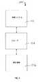
本発明の様々な側面によれば、ヒト表面組織の制御された熱傷に対する治療処置方法およびシステムは、音響エネルギー付与の精密な空間的および時間的制御を通して様々な形態、大きさ、および深度の熱損傷を制御可能に生じさせる能力に基づいている。図1を参照すると、典型的実施例によれば、典型的な治療処置システム100は、処置計画、音響エネルギーの制御および/または送出、および/または関心領域106に対する処置状況の監視を容易にすることができる制御システム102およびプローブシステム104を含む。関心領域106はヒト表面組織内に構成され、組織の外部表面直下から約30mm以上の深度を含む。 In accordance with various aspects of the present invention, methods and systems for the treatment of controlled burns of human surface tissue provide various forms, sizes, and depths of heat through precise spatial and temporal control of acoustic energy delivery. It is based on the ability to controllably cause damage. With reference to FIG. 1, according to an exemplary embodiment, an exemplary
治療処置システム100は、音響エネルギー付与の精密な空間的および時間的制御を通して関心領域106内の表面ヒト組織に熱傷の均一な損傷を制御可能に生じさせる能力を伴って構成され、つまり、プローブ104の制御は、そのような制御が組織に依存していない選択された時間および空間パラメータ内に限られている。典型的な実施例によれば、制御システム102およびプローブシステム104は音響エネルギーの分布の様式を制御することによって、音響エネルギーの空間的制御に対して適切に構成することができる。例えば、関心領域106に高周波の音波を当てる1つ以上の変換器構成の種類の選択、プローブシステム104が特定の方向またはそうでなければ関心領域106からの距離の変化を有する隣接する熱傷を生じさせるために関心領域106の一部または全体をスキャンするように構成されているような関心領域106に関連した音響エネルギーの送出に対するプローブシステム104の選択および配置、および/または他の環境的パラメータの制御、例えば音響結合インターフェースの温度を制御することができる、および/またはプローブ104のヒト組織に対する結合を通して、空間的制御を実現することができる。空間的制御パラメータに加え、制御システム102およびプローブシステム104もまた、組織の熱剥離を制御するために駆動振幅レベル、周波数/波形の選択、つまり振動の種類、突発または連続波形、およびタイミング配列、および他のエネルギー駆動特徴の調節および最適化などを通して、時間的制御に対して構成することができる。空間的および/または時間的制御はまた、様々な空間的および時間的特徴の監視などを通して、開ループおよび閉ループフィードバック配置を通しても促進することができる。結果として、6自由度内の音響エネルギーの制御、例えば空間的にX、YおよびZ域内、ならびにXY、YZおよびXZ域内の回転軸は、様々な形態、大きさ、および方向の均一な損傷を生成するために適切に達成することができる。
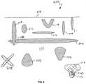
例えば、そのような空間的および/または時間的制御を通して、典型的な処置システム100は、熱傷の領域が任意の形態および大きさを持つことを可能にし、制御された様式で組織の破壊(剥離)が可能となる。図2を参照すると、1つ以上の熱損傷を組織の関心領域200内に生じさせることができ、そのような損傷は、外部表面の組織203までを含む、狭いまたは広い側方範囲、長いまたは短い軸長、および/または深いまたは浅い位置を有する。例えば、葉巻形損傷を、垂直配置204および/または水平配置206において生じさせることができる。また、雨滴形損傷208、扁平平面損傷210、円形損傷212および/または他のV字形/楕円形損傷214をとりわけ形成することができる。例えば、キノコ形損傷220が初期円形または葉巻形損傷222の初期生成などを通して生成され、成長する損傷224をさらに生成する熱膨張を引き起こす剥離超音波の継続的な適用によって、そのような熱膨張はキノコ形損傷220ができるまで続く。複数の形態を様々な大きさおよび方向で構成することもでき、例えば、損傷208は、全て空間的および/または時間的制御によって望ましい角度で右回りまたは左回りの回転方向にしたり、または選択した通りにより大きくまたはより小さくすることができる。さらに、島状の別々の破壊、つまり組織領域全体に離散した複数の損傷を、組織の関心領域200内の一部または全体に生成することもできる。また、隣接および/または重なった構造216を損傷の制御された構造より生成することができる。例えば、一連の1つ以上の交差した損傷218は、様々な種類の処置方法を容易にするように組織領域にそって生じさせることができる。 For example, through such spatial and/or temporal control, the
制御された熱傷の特定の構造は、望ましい組織および治療効果を達成するように選択される。例えば、熱および非熱流動、キャビテーション性、流体力学的、剥離性、収斂性、透熱性、および/または共鳴誘導型組織効果を含むがそれに限定されないあらゆる組織効果を実現することができる。そのような効果は、高度な実用性を提供するために関心領域200内の約0−30000μmの範囲に及ぶ処置深度で適切に実現することができる。 The specific structure of the controlled burn is selected to achieve the desired tissue and therapeutic effect. For example, any tissue effect can be achieved including, but not limited to, thermal and non-thermal flow, cavitational, hydrodynamic, exfoliating, astringent, heat permeable, and/or resonance-induced tissue effects. Such effects can be suitably achieved with treatment depths in the region of
再度図1を参照すると、制御システム102およびプローブシステム104で構成される典型的な治療処置システム100は、様々な構成も含み、様々な別の副システムおよびコンポーネントに細分することができる。例えば、治療処置システム100は音響エネルギーの空間的および/または時間的分布を容易にするために適切な位置に配置された様々なシステムおよびプローブコンポーネントに分けられる。また、制御システム102およびプローブシステム104は、プローブシステム104内の映像化変換器を操作および制御するように構成された制御システム102内の映像化副システム、例えば、組織パラメータ監視に対して構成された別々の映像化変換器および別々の治療変換器、または映像/治療化複合変換器などの他の副システムを含むことができる。 Referring again to FIG. 1, a typical
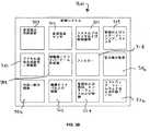
図3Aおよび3Bを参照すると、典型的実施例によれば、典型的な制御システム300は治療システムユーザーによって行われた調節可能な設定によれば治療処置過程全体の調整および制御に対して構成することができる。例えば、制御システム300は、電源コンポーネント302、感知および監視コンポーネント304、冷却および結合制御306、および/または処理および制御論理コンポーネント308を適切に含むことができる。制御システム300は、制御された熱傷に対する治療システムを実施するようにより多くのまたはより少ない副システムおよびコンポーネントを伴って様々な方法で構成および最適化することができ、図3Aおよび3Bの実施例は説明目的のためにすぎない。 Referring to FIGS. 3A and 3B, according to an exemplary embodiment, an
例えば、電源コンポーネント302に対して、制御システム300は変換器電子増幅器/ドライバ312によって必要とされる電力を含む、制御システム全体に対する電気エネルギーを提供するように構成された1つ以上の直流(DC)電力供給装置303を含むことができる。DC電流センサ305もまた、安全および監視目的で増幅器/ドライバ312へ流れる電力のレベルを確認するために備えることができる。 For example, for the power supply component 302, the
増幅器/ドライバ312は、多チャネルまたは単一チャネル電力増幅器および/またはドライバを含むことができる。変換器配列構成に対する典型的な実施例によれば、増幅器/ドライバ312はまた、配列集束を容易にするようにビーム作成器を伴って構成することもできる。典型的なビーム作成器は、関連切り替え論理を持つ発振器/デジタル制御された波形合成装置310によって電気的に励起することができる。 Amplifier/
電源コンポーネントはまた、様々なフィルター構成314も含むことができる。例えば、ドライバの能率および効率を向上させるために切替可能高調波フィルター、および/または整合を増幅器/ドライバ312の出力において使用することができる。電力検出コンポーネント316もまた、適切な操作および較正を確認するために含むことができる。例えば、典型的なプローブシステムへ流れる電力量を監視するために、電力およびその他エネルギーの検出コンポーネント316を使用することができる。 The power supply component can also include
様々な感知および監視コンポーネント304もまた、制御システム300内で適切に実施することができる。例えば、典型的な実施例によれば、監視、感知、および相互作用制御コンポーネント324は、関心領域からの音響または他の空間的および時間的情報などの情報を受け取って処理するために、変換器プローブ104内で実施される様々な動作検出システムとともに操作するよう構成することができる。感知および監視コンポーネントはまた、様々な制御、相互作用およびスイッチ309および/または電力検出装置316も含むことができる。そのような感知および監視コンポーネント304は、処置システム100内の開ループおよび/または閉ループフィードバックシステムを容易にすることができる。さらに、監視、感知および相互作用制御コンポーネント324は、一次元、二次元および/または三次元映像化機能に対して構成された映像化システムを含むことができる。そのような映像化システムは、写真および他の視覚光学的方法、磁気共鳴映像法(MRI)、コンピュータ断層撮影法(CT)、光干渉断層撮影法(OCT)、電磁気、マイクロ波、またはラジオ周波数(RF)方法、陽電子放出断層撮影法(PET)、赤外線、超音波、音響または他の適切な視覚化の方法、局所化、または関心領域106の監視のうち少なくとも1つに基づく映像診断法を含むことができる。さらに、温度測定装置およびコンポーネントなどの様々なその他の組織パラメータ監視コンポーネントを、監視、感知および相互作用制御コンポーネント324内に構成することができ、そのような監視装置は未知のまたは以下に考案される映像診断法を含む。 Various sensing and monitoring components 304 may also be suitably implemented within
冷却/結合制御システム306は、典型的なプローブ104からの廃熱を除去し、表面組織接合部分および組織へのさらなる深部において制御された温度を提供し、および/または変換器プローブ104から関心領域106へ音響結合を提供するために備えることができる。そのような冷却/結合制御システム306はまた、様々な結合およびフィードバックコンポーネントとともに、開ループおよび/または閉ループフィードバック配置の両方において操作するよう構成することもできる。 The cooling/
処理および制御論理コンポーネント308は、ファームウェアおよび制御ソフトウェア326を含むマイクロコントローラ、マイクロプロセッサ、フィールド・プログラマブル・ゲート・アレイ(FPGA)、コンピュータボード、および関連コンポーネントのうちの1つ以上といった様々なシステムプロセッサおよびデジタル制御論理307を含むことができ、これはユーザー制御および相互作用回路、ならびに通信、表示、相互作用、保存、文書化、および他の有用な機能に対する入力/出力回路およびシステムに結びつく。システムソフトウェアおよびファームウェア326は、全ての初期化、タイミング、レベル設定、監視、安全性監視、およびユーザー定義の処置目的を達成するために必要なその他全てのシステム機能を制御する。さらに、様々な制御スイッチ308もまた、操作を制御するように適切に構成することができる。 The processing and
典型的な変換器プローブ104もまた、様々な様式で構成され、その操作を容易にするように様々な実施例において多数の再利用可能および/または使い捨てコンポーネントおよび部品を含むことができる。例えば、変換器プローブ104は、組織接合部分に対する変換器の結合を容易にするためのあらゆる種類の変換器プローブ筐体または配置内で構成することができ、そのような筐体は特定の処置適用によって様々な形態、輪郭および構成を含む。例えば、典型的な実施例によれば、変換器プローブ104は、組織接合部分に対して押し下げられてよく、それにより血液還流が部分的または完全に遮断され、組織が表面の処置関心領域106において扁平になる。変換器プローブ104は、1つ以上のシリアルEEPROM(メモリ)などのプローブ取っ手、電子整合、変換器使用歴および較正を認証するために、例えば、電子的に切替可能である電子整合、マルチプレクサ回路および/または開口/要素選択回路、および/またはプローブ識別装置などのあらゆる種類の整合を含むことができる。変換器プローブ104はまた、ケーブルおよび接合具、動作機構、動作センサおよびエンコーダ、熱監視センサ、および/またはユーザー制御および状態関連スイッチ、およびLEDなどの指示器を含むこともできる。例えば、プローブ104における動作機構は、複数の損傷を制御可能に生じさせるために使用することができ、またプローブ動作の感知自体は、複数の損傷を制御可能に生じさせ、および/または、例えばプローブ104が突然引っ張られたり落とされた場合に安全目的で損傷の生成を止めるために使用することができる。また、プローブ104の空間的位置および姿勢が制御可能に損傷を生成することを補うために制御システムに送られることによって、外部動作エンコーダアームを使用中にプローブを保持するために使用することができる。さらに、様々な典型的な実施例によれば、表面形状測定装置などの感知機能性またはその他の映像診断法をプローブに組み込むことができる。 The
図4Aおよび4Bを参照すると、典型的な実施例によれば、変換器プローブ400は、制御インターフェース402、変換器404、結合コンポーネント406、および監視/感知コンポーネント408、および/または動作機構410を含むことができる。しかしながら、変換器プローブ400は、制御された熱傷に対する超音波エネルギーを提供するようにより多くのまたはより少ない部品およびコンポーネントを伴って様々な方法で構成および最適化することができ、図4Aおよび4Bの実施例は説明目的のためにすぎない。 4A and 4B, according to an exemplary embodiment, the
制御インターフェース402は、変換器プローブ400の制御を容易にするように制御システム300との相互作用のために構成されている。制御インターフェースコンポーネント402は、マルチプレクサ/開口選択424、切替可能な電子整合ネットワーク426、シリアルEEPROMおよび/または他の処理コンポーネントおよび整合およびプローブ使用情報403、およびインターフェース接合具432を含むことができる。 The
結合コンポーネント406は、関心領域への変換器プローブ400の結合を用意にするように様々な装置を含むことができる。例えば、結合コンポーネント406は、超音波エネルギーおよび信号の音響結合のために構成された冷却および音響結合システム420を含むことができる。多岐管などの可能な連結部を有する音響冷却/結合システム420は、関心領域内へ音を合わせ、接合部分および組織へのさらなる深度において温度を制御し、液体充填レンズの集束を提供し、および/または変換器の廃熱を除去するために活用することができる。結合システム420は、空気および他の気体、水および他の液体、ゲル、固体、および/またはその組み合わせ、または変換器能動素子412と関心領域との間で信号の伝達を可能にするその他の媒体を含む、様々な結合媒体の使用を通してそのような結合を容易にすることができる。結合機能の提供に加え、典型的な実施例によれば、結合システム420はまた、処置適用中に温度制御を提供するために構成することもできる。例えば、結合システム420は、結合媒体の温度を適切に制御することによって、接合部分表面または変換器プローブ400と関心領域との間の領域、および組織へのさらなる深部の制御された冷却のために構成することができる。そのような結合媒体に対する適切な温度は様々な様式で達成することができ、熱電温度計、サーミスタ、または結合媒体の温度測定のために構成されたその他の装置またはシステムなどの様々なフィードバックシステムを活用することができる。そのような制御された冷却は、変換器プローブ400の空間的および/または熱エネルギー制御をさらに容易にするように構成することができる。
典型的な実施例によれば、さらに図11を参照するが、音響的結合および冷却1140は、変換器プローブ1104からのエネルギーおよび映像化信号を関心領域1106間で音響的に結合させ、損傷を制御するために関心領域接合部分1110および組織内へのさらなる深部へプローブにおいて熱制御を提供し、領域1144において変換器プローブからの可能な廃熱を除去するように備えることができる。温度監視は、温度測定機構1148を提供し、制御システム1102および熱制御システム1142を介して制御するように、熱センサ1146を介して結合接合部分に備えることができる。熱制御はヒートシンクまたは自然伝導および伝達などを介する、またはペルチェ熱電冷却器、冷却剤、またはポンプ、液タンク、気泡検出、流量センサ、流路/管1144および熱制御1142から成る液体利用システムなどを伴う能動冷却を介する受動冷却より構成することができる。 11, the acoustic coupling and cooling 1140 acoustically couples the energy and imaging signals from the
引き続き図4に関して、監視および感知コンポーネント408は、例えば様々な空間的および時間的特徴を監視する開ループおよび閉ループフィードバック配置を通した空間的および/または時間的制御を容易にするように、様々な動作および/または位置センサ416、温度監視センサ418、ユーザー制御およびフィードバックスイッチ414、および制御システム300による制御を容易にするための類似したコンポーネントを含むことができる。 Continuing to refer to FIG. 4, the monitoring and
動作機構410は、手動操作、機械的配置、またはその組み合わせを含むことができる。例えば、動作機構422は、変換器プローブ400の動作および位置を決定し有効にするように、加速度計、エンコーダまたはその他の位置/方向装置416の使用などを通して、制御システム300によって適切に制御することができる。直線、回転、または可変動作は、例えば処置適用および組織輪郭表面によって容易にすることができる。 The
変換器404は、音響エネルギー付与の精密な空間的および時間的制御を通して、関心領域内の表面ヒト組織における熱傷の均一な損傷を生じさせるために構成された1つ以上の変換器を含むことができる。変換器404はまた、1つ以上の変換要素および/またはレンズ412を含むこともできる。変換要素は、チタン酸ジルコン酸鉛(PZT)などの圧電的活物質、または圧電性セラミック、結晶、プラスチック、および/または複合材料などのその他の圧電的活物質、ならびにニオブ酸リチウム、チタン酸鉛、チタン酸バリウム、および/またはメタニオブ酸鉛を含むことができる。圧電的活物質に加えて、またはその代わりに、変換器404は放射線および/または音響エネルギーの生成のために構成されたその他の材料を含むことができる。音響整合層および/または減衰を、望ましい電子音響反応を達成するように必要に応じて使用することもできる。
典型的な実施例によれば、変換器404の変換要素の厚さは一定となるように構成することができる。つまり、変換要素412は実質的に常に同じである厚さを有するように構成することができる。別の典型的な実施例によれば、変換要素412の厚さはまた、可変となるように構成することもできる。例えば、変換器404の変換要素412は、より低い範囲の中央動作周波数、例えば約1kHzから3MHzを提供するように選択された第一の厚さを有するよう構成することができる。変換要素404はまた、より高い範囲の中央動作周波数、例えば約3から100MHz以上を提供するように選択された第二の厚さを有するよう構成することもできる。変換器404は、望ましい反応を生成するために適切な出力を提供するように少なくとも2つ以上の周波数で励起する単一広帯域変換器として構成され得る。変換器404はまた、各変換器が1つ以上の変換要素を含む、2つ以上の個別変換器として構成され得る。変換要素の厚さは、望ましい処置範囲において中央動作周波数を提供するように構成することができる。例えば、変換器404は、約1kHzから3MHzの中央周波数範囲に相当する厚さを有する第一変換要素を伴って構成された第一変換器、および約3MHzから100MHz以上の中央周波数に相当する厚さを有する第二変換要素を伴って構成された第二変換器を含むことができる。 According to an exemplary embodiment, the thickness of the transducer elements of
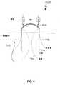
変換器404は、一次元、二次元、および環状配列を含む集束、平面、または非集束の単一要素、多要素、または配列変換器、直線、曲線、扇形、および球形配列、球状、円柱状、および/または電子的な集束、非集束、および/またはレンズ効果源より成り立つことができる。例えば、図5に表された典型的な実施例を参照すると、変換器500は位相合わせを容易にするよう音響配列として構成することができる。つまり、変換器500は、可変電子時間遅延を介した様々な位相によって操作することができる電子開口の配列として構成することができる。「操作する」という意味において、変換器500の電子開口は、電子時間遅延によって起こる位相変化に適合するエネルギービームの産出および/または送出をするように、操作、駆動、使用、および/または構成することができる。例えば、これらの位相変化は、非集束ビーム、平面ビーム、および/または集束ビームを送出するために使用することができ、それぞれは関心領域510において異なる生理学的効果を達成するように併用することができる。変換器500は、ソフトウェア、および/または1つ以上の電子時間遅延を伴う電子時間遅延を伴う位相開口配列の生成、産出、および/または駆動のためのその他のハードウェアをさらに含むことができる。
変換器500はまた、様々な周波数を使用して1つ以上の関心領域に対する集中的な処置を提供するように構成することもできる。集中的な処置を提供するために、変換器500は処置を容易にするように1つ以上の可変深度を伴って構成することができる。例えば、変換器500は、本発明との少なくとも1人の共通発明者および共通出願人を有する「可変深度超音波に対するシステムおよび方法」と題され、2004年6月に提出された米国特許出願第10/944,500号にて開示されている可変深度装置を伴って構成し、これを参照することにより組み込むことができる。また、変換器500は、本発明との少なくとも1人の共通発明者および胸中出願人を有する「多方向変換器による超音波処理に対する方法およびシステム」と題され、2004年9月16日に提出された米国特許出願第10/944,499号にて開示されているように、低調波またはパルスエコー映像化を有効にすることによって1つ以上の関心領域510を処置するよう構成することもでき、これを参照することにより組み込むこともできる。
さらに、液体充填レンズといった、様々な機械的レンズまたは可変焦点レンズも、音場を集束および/または非集束するために使用することができる。例えば、図6Aおよび6Bに表されている典型的な実施例を参照すると、変換器600は、関心領域610の処置において柔軟性の向上を容易にするための1つ以上の変換要素606と併用して電子集束配列604を伴って構成することもできる。配列604は、変換器502と同様の様式で構成することができる。つまり、配列604は、例えばT1、T2・・・Tjといった可変電子時間遅延を介した様々な位相によって操作することができる電子開口の配列として構成することができる。「操作する」という意味において、配列604の電子開口は、電子時間遅延によって起こる位相変化に適合する様式で、エネルギーの産出および/または送出をするように、操作、駆動、使用、および/または構成することができる。例えば、これらの位相変化は、非集束ビーム、平面ビーム、および/または集束ビームを送出するために使用することができ、それぞれは関心領域610において異なる生理学的効果を達成するように併用することができる。In addition, various mechanical or variable focus lenses, such as liquid filled lenses, can also be used to focus and/or defocus the sound field. For example, referring to the exemplary embodiments depicted in FIGS. 6A and 6B, the
変換要素606は、凹面、凸面、および/または平面になるよう構成することができる。例えば、図6Aに表されている典型的な実施例において、変換要素606Aは、関心領域610の処置に対する集束エネルギーを提供するために凹面になるよう構成されている。付加的な実施例が「可変深度変換器システムおよび方法」と題された米国特許出願第10/944,500号において開示されており、再度これを参照することにより組み込むことができる。 The
図6Bに表されている別の典型的な実施例において、変換要素606Bは、関心領域610に実質的に一定のエネルギーを提供するために、実質的に平面となるよう構成することができる。図6Aおよび6Bは、それぞれ凹面および実質的平面として構成された変換要素604で典型的な実施例を表しているが、変換要素604は、凹面、凸面、および/または実質的平面となるよう構成することができる。また、変換要素604は、凹面、凸面、および/または実質的平面構造のいずれの組み合わせとなるように構成することができる。例えば、第一変換要素を凹面となるよう構成することができる一方で、第二変換要素を実質的平面となるよう構成することができる。 In another exemplary embodiment depicted in FIG. 6B, the conversion element 606B can be configured to be substantially planar to provide a substantially constant energy to the region of
図8Aおよび8Bを参照すると、変換器404は、単一要素配列として構成されてもよく、単一要素802(例えば、様々な構造および材料の変換要素)は、複数のマスク804を伴って構成されてもよく、そのようなマスクはセラミック、金属、または要素802からのエネルギー分布の遮蔽および変更のための他の材料または構造を含み、エネルギー分布配列808を作成することができる。マスク804は、要素802に直接結合したり、または適切な固体または液体材料などの隔離部806で分離することができる。 With reference to FIGS. 8A and 8B, the
典型的な変換器404は、平面、集束または/および非集束音響得寝る偽を提供するよう環状配列として構成することもできる。例えば、図10Aおよび10Bを参照すると、典型的な実施例によれば、環状配列1000は、複数の環1012、1014、1016からNを含むことができる。複数の環1012、1014、1016からNは、個々の要素一式に機械的および電子的に分離することができ、平面、集束、および非集束波を作成することができる。例えば、そのような波は相当する送信および/または受信遅延τ1、τ2、τ3・・・τNを調節する方法などによって、軸上に集中させることができる。電子集束は様々な深度位置に沿って適切に移動させることができ、可変強度またはビーム密度を有効にすることができる一方、電子非集束は変化する非集束量を有することができる。典型的な実施例によれば、レンズおよび/または凸面または凹面形環状配列1000はまた、あらゆる時間遅延差が軽減できるために集束または非集束を補助するように備えることもできる。プローブおよび/または従来のロボットアーム機構の使用などを通した、一次、二次、または3次元における、またはあらゆる経路に沿った環状配列800の動作は、関心領域内のある大きさまたは相当する空間をスキャンおよび/または処置するよう実施することができる。The
変換器404はまた、映像化/治療機能のためにその他の環状または非配列構成において構成することもできる。例えば、図10C〜10Fを参照すると、変換器は治療要素1014を伴って構成された映像化要素1012を含むことができる。要素1012および1014は単一変換要素を含むことができ、例えば、図10Cに図示されているように治療要素1014間の穴または隙間内に構成された映像化要素1012などの映像化/治療複合要素、または別々の要素が、同一変換要素内または図10Dに図示されているような別々の映像化および治療要素の間に電子的に分離することができ1022、および/または隔離部1024またはその他の整合層、またはそれらの組み合わせを含むことができる。例えば、特に図10Fに関して、変換器は、集束、非集束または平面エネルギー分布に対して構成された段階的構成レンズを含む治療要素1014を伴い、集束、非集束または平面エネルギー分布に対して構成された表面1028を持つ映像化要素1012を含むことができる。
本発明の様々な典型的実施例によれば、変換器404は、1つ以上の関心領域への集束音響エネルギーに対する一次、二次、および/または三次元処置適用を提供するように構成することができる。例えば、上記で検討しているように、変換器404は、例えば、副変換要素の単一配列を含む変換器602などの一次元配列を形成するように適宜さいの目に切られることができる。 According to various exemplary embodiments of this invention, the
別の典型的な実施例によれば、変換器404は二次元配列を形成するように二次元に適宜さいの目に切られてよい。例えば、図9を参照すると、典型的な二次元配列900は、複数の二次元部分902へと適宜さいの目に切られてよい。二次元部分902は、特定の深度における処置領域に集束するように適切に構成され得るため、処置領域のそれぞれの薄片904を提供する。結果として、二次元配列900は、処置領域の映像場所の二次元薄片切断を提供することができる。 According to another exemplary embodiment, the
別の典型的な実施例によれば、変換器404は、三次元処置を提供するように適切に構成することができる。例えば、関心領域の三次元処置を提供するため、再度図1を参照すると、三次元システムは、例えば、制御システム102などの制御システム内に含まれた三次元グラフィックソフトウェアを活用するものなどの、適合アルゴリズムを伴って構成されたプローブ104内の変換器を含むことができる。適合アルゴリズムは、関心領域に関する二次元映像、温度および/または処置、またはその他組織のパラメータ情報を受信し、受信した情報を処理し、そして相当する三次元映像、温度および/または処置情報を提供するように適切に構成することができる。 According to another exemplary embodiment, the
典型的な実施例によれば、再度図9を参照すると、典型的な三次元システムは、処置領域の異なる映像面から薄片904を適切に受信し、受信した情報を処理し、そして例えば三次元映像、温度および/または処置情報などの体積情報906を提供するように適合アルゴリズムを伴って構成することができる。さらに、適合アルゴリズムによって受信した情報を処理した後、二次元配列900は望ましい体積領域906に対する治療加熱を適切に提供することができる。 Referring again to FIG. 9, according to an exemplary embodiment, a typical three-dimensional system properly receives
別の典型的な実施例によれば、三次元ソフトウェアなどの適合アルゴリズムの活用よりもむしろ、三次元映像および/または温度情報を提供するために、典型的な三次元システムは、目標領域に関連して様々な回転および/または翻訳位置から操作するようにプローブ配置内に構成された単一変換器404を備えることができる。 According to another exemplary embodiment, a typical three-dimensional system is associated with a target area to provide three-dimensional image and/or temperature information, rather than utilizing adaptive algorithms such as three-dimensional software. A
変換器404に対する様々な構造をさらに図示するために、図7を参照すると、超音波治療変換器700は、単一焦点、複数焦点の配列、複数焦点の場所、および/または回折パターンに対して構成することができる。変換器700はまた、レンズ、音響コンポーネント、および機械的/電子集束を持つ、または持たない単一要素、多要素、環状配列、一次、二次、または三次元配列、広帯域変換器、および/またはそれらの組み合わせを含むこともできる。 To further illustrate various structures for the
球状集束単一要素702、環状配列704、減衰領域を持つ環状配列706、直線集束単一要素708、一次元直線配列710、上昇集束を持つまたは持たない凹面または凸面形による一次元曲線配列、二次元配列、および変換器の三次元空間的配置として構成された変換器は、治療および/または映像化および音響監視機能を実施するために使用することができる。変換器構成については、集束/非集束は、図10Fに図示されているような機械的集束720、凸面レンズ722、凹面レンズ724、複合または複数レンズ726、平面形728、または段階的形を介して1つの面または2つの面で行うことができる。あらゆる変換器または変換器の組み合わせが、処置に対して活用することができる。例えば、環状変換器は、映像化変換器および治療変換器が、図10C―10Fに図示されているように異なる音響レンズおよびデザインを持つような、治療のために設けられた外側部および広帯域映像化のために設けられた内部ディスクとともに使用することができる。 Spherical focusing
様々な変換器構造をさらに理解すると、再度図2を参照して、広範囲の損傷に貢献する変換器または複数の変換器の幾何学的構成がどのように作用するかがさらに理解することができる。例えば、葉巻形損傷204および206は、球状集束源、および/または扁平源からの平面損傷210より生じさせることができる。凹面平面源および配列は、「V字形」または楕円形損傷214を生成することができる。直線配列などの電子配列は、様々な深度で様々な付加的損傷を形成するために使用することができる非集束、平面、または集束音響ビームを生じることができる。配列は単独または1つ以上の平面または集束変換器と併用して使用することができる。そのような併用された変換器および配列は、非常に広い範囲の音響およびその関連利益を産出することができる。固定焦点および/または可変焦点レンズまたは複数レンズは、処置の柔軟性をさらに向上させるために使用することができる。適切な電力処理能力を持つ液体充填レンズ、ゲル充填または固体ゲルレンズ、ゴムまたは複合レンズなどの表面組織よりも低い音速を持つ凸面形レンズを活用することができ、または凹面形の薄型レンズを活用し、組織よりも高い速度を持つ材料または合成物から構成することができる。変換器源および構成の構造が、上記で示唆しているように特定形態の損傷を容易にすることができる一方、その他の空間的パラメータならびに時間的パラメータがあらゆる変換器構造および源内でさらなる形態を容易にすることができるので、そのような構造はそれらの特定形態に限定されない。 With a further understanding of the various transducer structures, reference may again be made to FIG. 2 to further understand how the transducer or multiple transducer geometry contributes to a wide range of damages. .. For example, cigar-shaped
組織内に生成された生理学的効果は、変換器構成、距離/配置、方向、および/または動作などのエネルギーの空間的配置だけでなく、時間的および時間依存性特徴によっても影響される。例えば、時間的制御に関して、各配列、二次元配列、または単一要素変換器を様々な送信周波数で使用することができ、約1MHzから40MHzの範囲の中心周波数を持つ、またはエネルギーの単一広帯域パルスさえも持つ広帯域、または比較的低い帯域のどちらかとなり得る。振幅レベルおよび周波数選択は、さらに選択肢を広げるために処置中に変更することができる。送信時間またはエネルギーレベルは、組織の熱容量を越え、制御された熱傷(壊死)および/または剥離を生成するように構成される。熱容量は、生体組織が機能を失うために十分なエネルギー/熱の最小量である。これに関連して、熱容量は生体組織破壊を引き起こすためのエネルギーの最小量である。 The physiological effects produced in the tissue are influenced not only by the spatial arrangement of energy, such as transducer configuration, distance/placement, orientation, and/or motion, but also by temporal and time-dependent features. For example, for temporal control, each array, two-dimensional array, or single element transducer can be used at various transmit frequencies, with a center frequency in the range of about 1 MHz to 40 MHz, or a single wide band of energy. It can be either wideband, even with pulses, or relatively lowband. Amplitude level and frequency selection can be changed during the procedure to further expand options. The transmission time or energy level is configured to exceed the heat capacity of the tissue and produce controlled burns (necrosis) and/or ablation. Heat capacity is the minimum amount of energy/heat sufficient to cause biological tissue to lose function. In this context, heat capacity is the minimum amount of energy to cause tissue destruction.
そのような空間的および/または時間的制御はまた、開ループおよび/または閉ループフィードバックシステムを通して向上させることもできる。例えば、図12Aを参照すると、処置システム1200は、関心領域1206を処置するためのプローブ1204を伴って構成された制御システム1102を持つ開ループフィードバック構造を含むことができる。制御システム1202は、制御システム300内の様々な制御コンポーネントなどの制御コンポーネント1208、表示部1210、または組織パラメータ監視コンポーネント1212、またはその他の感知または監視コンポーネントを含むことができる。表示部1210は、処置領域、および/または空間的または時間的パラメータなどの映像を図示するために構成された表示部を含むことができる。そのような開ループシステムにおいて、システムユーザーは、映像および/またはその他の空間的または時間的 パラメータを適切に監視し、そして特定の処置目的を達成するために同一物を調整または修正することができる。開ループフィードバック構成のかわりに、または併用して、図12Bに図示されている典型的な実施例を参照すると、典型的な処置システム1200は、例えば、制御コンポーネント1208に提供するためにドライバ1214および増幅器1216内、または処置システム1100のその他の制御可能な側面内で信号を生成するように映像および/または空間的/時間的パラメータを監視コンポーネント1212内で適切に監視できるような閉ループフィードバックシステムを含むことができる。結果として、出力の閉ループ制御およびプローブ1204の操作を実現することができる。 Such spatial and/or temporal control can also be enhanced through open loop and/or closed loop feedback systems. For example, referring to FIG. 12A,
典型的な処置システムの操作中、選択されたサイズ、形態、方向の損傷構成が決定される。その損傷構成に基づき、適切な時間的パラメータとともに1つ以上の空間的パラメータが選択され、これは望ましい均一な損傷をもたらす組み合わせである。そして変換器の操作は、均一な損傷または損傷を提供するために開始することができる。開および/または閉ループフィードバックシステムもまた、頭角損傷をさらに制御するために、空間的および/または時間的特徴、および/またはその他の組織パラメータ監視を監視するように実施することができる。 During operation of a typical treatment system, lesion configurations of selected size, morphology, and orientation are determined. Based on its damage configuration, one or more spatial parameters with appropriate temporal parameters are selected, which is the combination that results in the desired uniform damage. And operation of the transducer can be initiated to provide uniform damage or damage. Open and/or closed loop feedback systems can also be implemented to monitor spatial and/or temporal characteristics, and/or other tissue parameter monitoring to further control the anterior corner injury.
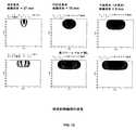
図13を参照すると、熱損傷成長を図示しているシミュレーション結果の収集を解説する。そのような損傷成長は、球状集束、円柱状集束、および平面(非集束)源で公称源音響パワーレベルであるW0およびそのレベルの2倍である2W0において生成されたが、ここで開示されているように変換器のあらゆる構成を活用することができる。熱輪郭は、異なる時間で組織が65℃に達した時点を示している。円柱状集束源に対する輪郭は、短い軸に沿っているか、またはいわゆる上昇面である。この図は、異なるパワーレベルおよび源形状を持つ可能な損傷の異なる形態を強調している。また、図14を参照すると、シミュレーション結果と隣接して化学染色したブタ組織の顕微鏡写真を示して一対の損傷およびシミュレーション結果を図示する。また、図15を参照すると、オタマジャクシ形損傷および楔形損傷を強調し、化学染色したブタ組織の顕微鏡写真を示して別の一対の損傷およびシミュレーション結果を図示する。Referring to FIG. 13, the collection of simulation results illustrating thermal damage growth is illustrated. Such damage growth was produced at spherical-focused, cylindrically-focused, and planar (unfocused) sources at the nominal source acoustic power level W0 and twice that level, 2W0 , but disclosed herein. Any configuration of converter can be utilized as described. The thermal contours show the time points when the tissue reached 65°C at different times. The profile for a cylindrical focusing source is along the short axis or is the so-called rising surface. This figure highlights different forms of possible damage with different power levels and source shapes. Referring also to FIG. 14, a pair of lesions and simulation results are illustrated with a photomicrograph of chemically stained porcine tissue adjacent to the simulation results. Referring also to FIG. 15, a pair of lesions and simulation results are shown with a photomicrograph of chemically stained pig tissue highlighting tadpole and wedge lesions.
要約すると、送信電力レベルおよびタイミング、送信周波数および/または駆動波形の制御などを通して時間的音場の調節と併用する、大きさ、要素構成、電子または機械的レンズ、音響結合および/または冷却などの変換器の種類および分布を介した音場の空間的分布の調節は、様々な大きさ、形態、および深度の制御された熱損傷の達成を容易にすることができる。さらに、人体の修復生物学的反応は、表面ヒト組織に対する望ましい作用をさらに引き起こすことができる。 In summary, such as size, component configuration, electronic or mechanical lens, acoustic coupling and/or cooling, used in conjunction with temporal sound field adjustments such as through control of transmit power level and timing, transmit frequency and/or drive waveforms. Adjusting the spatial distribution of the sound field via transducer type and distribution can facilitate the achievement of controlled thermal damage of varying magnitude, morphology, and depth. Moreover, the repair biological response of the human body can further cause desirable effects on surface human tissues.
本発明を様々な典型的な実施例を参照して上記に説明した。しかしながら、当業者には、本発明の範囲を逸脱しない範囲で変更および修正が可能であることが認識されるであろう。例えば、様々な操作上のステップ、ならびに操作上のステップを実行するためのコンポーネントは、特定の適用によって、またはシステムの操作に関連したあらゆる数の費用関数の考慮において、代替方法で実施することができ、例えば様々なステップを削除、修正、または他のステップと組み合わせたりすることができる。このようなおよび他の変更または修正も、以下の特許請求の範囲に記載のとおり、本発明の範囲内に含まれることを意図する。 The invention has been described above with reference to various exemplary embodiments. However, one of ordinary skill in the art will recognize that changes and modifications can be made without departing from the scope of the present invention. For example, various operational steps, as well as components for performing operational steps, may be implemented in alternative ways, depending on the particular application, or in consideration of any number of cost functions associated with the operation of the system. Yes, various steps can be deleted, modified, or combined with other steps, for example. Such and other changes or modifications are intended to be included within the scope of the invention as set forth in the following claims.
Claims (19)
Translated fromJapaneseプローブであって、該プローブは、
組織の関心領域を治療するように構成された少なくとも1つの凹面球状集束超音波治療要素であって、周波数において音響エネルギーを放出するように構成された少なくとも1つの凹面球状集束超音波治療要素と、
該プローブ内で該少なくとも1つの凹面球状集束超音波治療要素の自動化された直線的な移動を行うように構成された自動化動作機構であって、該自動化動作機構は、該プローブ内の該少なくとも1つの凹面球状集束超音波治療要素の所望の位置または方向を決定するように構成されたエンコーダおよび位置/方向装置からなる群のうちの少なくとも1つを含み、該自動化動作機構は、該プローブ内で該少なくとも1つの凹面球状集束超音波治療要素を該所望の位置または方向へと自動的に移動させ、これにより、皮膚表面から表面ヒト組織の固定された深さにおいて、損傷の大きさと形態と方向性とを有する複数の熱損傷を制御可能に形成する、自動化動作機構と
を含む、プローブと、
該プローブと通信する制御システムであって、該プローブを制御して該複数の熱損傷を生成するように構成される制御システムと
を含む、治療処置システム。A therapeutic treatment system configured to deliver controlled thermal damage to a region of interest in tissue, the treatment system comprising:
A probe, wherein the probe is
And at least one concave spherical focused ultrasound treatment element that is configured to treat the area of interest of the organization, at least one concave spherical focused ultrasound treatment element configured to emitacoustic energyTe frequency smell When,
An automated actuation mechanism configured to provide automated linear movement of the at least one concave spherical focusedultrasound therapeutic element within the probe, the automated actuation mechanism comprising: A concave spherical focusedultrasound therapeutic element comprising at least one of the group consisting of an encoder and a position/orientation device configured to determine a desired position or orientation, the automated operating mechanism within the probe. Automatically moving the at least one concave spherical focusedultrasound therapeutic element to the desired position or orientation, thereby causing the magnitude and morphology and orientation of the lesion at a fixed depth of surface human tissue from the skin surface. A controllable formation of a pluralityof thermal damages with an active motion mechanism,
A control system in communication with the probe, the control system configured to control the probe to generate the plurality of thermal lesions.
前記制御システムと相互作用する制御インターフェースと、
前記少なくとも1つの凹面球状集束超音波治療要素を前記関心領域に音響的に結合する結合コンポーネントと、
前記制御システムによる制御を促進する複数の動作センサまたは位置センサを含む監視コンポーネントとセンサコンポーネントと
をさらに含む、請求項1〜3のいずれか一項に記載の治療処置システム。The probe is
A control interface interacting with the control system,
A coupling component acoustically coupling the at least one concave spherical focusedultrasound therapeutic element to the region of interest;
The therapeutic treatment system according to any one of claims 1 to 3, further comprising: a monitoring component including a plurality of motion sensors or position sensors that facilitate control by the control system and a sensor component.
プローブであって、該プローブは、
組織の関心領域を治療するように構成された少なくとも1つの凹面球状集束超音波治療要素であって、周波数において音響エネルギーを放出するように構成された凹面球状集束超音波治療要素と、
該プローブ内における該少なくとも1つの凹面球状集束超音波治療要素の自動化された直線的な移動を行うように構成された自動化動作機構であって、該自動化動作機構は、該プローブ内の該少なくとも1つの凹面球状集束超音波治療要素の所望の位置または方向を決定するように構成されたエンコーダおよび位置/方向装置からなる群のうちの少なくとも1つを含み、該自動化動作機構は、該プローブ内で該少なくとも1つの凹面球状集束超音波治療要素を該所望の位置または方向へと自動的に移動させ、これにより、表面ヒト組織の表面から固定された深さにおいて、損傷の大きさと形態と方向性とを有する複数の熱損傷を制御可能に形成する、自動化動作機構と
を含む、プローブ
を含む、超音波治療処置システム。An ultrasonic therapeutic treatment system configured to deliver controlled thermal damage to a region of interest in tissue, the treatment system comprising:
A probe, wherein the probe is
At least one concave spherical focused ultrasound therapeutic element configured to treat a region of interest in tissue, the concave spherical focused ultrasonic therapeutic element configured to emit acoustic energy at a frequency;
An automated actuation mechanism configured to provide automated linear movement of the at least one concave spherical focused ultrasound treatment element within the probe, the automated actuation mechanism comprising: A concave spherical focused ultrasound therapeutic element comprising at least one of the group consisting of an encoder and a position/orientation device configured to determine a desired position or orientation, the automated operating mechanism within the probe. Automatically moving the at least one concave spherical focused ultrasound treatment element to the desired position or orientation, thereby allowing the magnitude, morphology and orientation of the lesion at a fixed depth from the surface of the surface human tissue. And an automated operating mechanism for controllably forming a plurality of thermal damages having a probe.
プローブであって、該プローブは、
レンズなしで組織の第1の関心領域を治療するように構成された第1の凹面球状集束超音波変換器と、
レンズなしで組織の第2の関心領域を治療するように構成された第2の凹面球状集束超音波変換器であって、該第2の関心領域は、該第1の関心領域よりも下に位置し、該第1の凹面球状集束超音波変換器が第1の周波数において音響エネルギーを放出するように構成され、かつ、該第2の凹面球状集束超音波変換器が該第1の周波数とは異なる第2の周波数において音響エネルギーを放出するように構成されることにより、該第1の凹面球状集束超音波変換器および該第2の凹面球状集束超音波変換器が組み合わさって、皮膚表面から表面ヒト組織の深さにおいて、損傷の大きさと形態と方向性とを有する複数の熱損傷を制御可能に形成するようになっている、第2の凹面球状集束超音波変換器と、
該プローブ内で該第1の凹面球状集束超音波変換器の自動化された直線的な移動を行うように構成された自動化直線動作機構であって、該自動化動作機構は、該プローブ内の該第1の凹面球状集束超音波変換器の所望の位置または方向を決定するように構成されたエンコーダおよび位置/方向装置からなる群のうちの少なくとも1つを含み、該自動化直線動作機構は、該プローブ内で該第1の凹面球状集束超音波変換器を該所望の位置または方向へと自動的に移動させる、自動化直線動作機構と
を含む、プローブと、
該プローブと通信する制御システムであって、該プローブを制御して該複数の熱損傷を生成するように構成されている制御システムと
を含む、治療処置システム。A therapeutic treatment system configured to deliver controlled thermal damage to a region of interest in tissue, the treatment system comprising:
A probe, wherein the probe is
A first concave spherical focused ultrasound transducer configured to treat a first region of interest of tissue without a lens;
A second concave spherical focused ultrasound transducer configured to treat a second region of interest of tissue without a lens, wherein the second region of interest is below the first region of interest. Is located, the first concave spherical focused ultrasound transducer is configured to emit acoustic energy at a first frequency, and the second concave spherical focused ultrasound transducer is coupled to the first frequency. Are configured to emit acoustic energy at different second frequencies such that the first concave spherical focused ultrasonic transducer and the second concave spherical focused ultrasonic transducer combine to form a skin surface. A second concave spherical focused ultrasound transducer adapted to controllably form a plurality of thermal lesions having a size, morphology and orientation of lesions at the depth of the surface human tissue;
An automated linear motion mechanism configured to perform an automated linear movement of the first concave spherical focused ultrasonic transducer within the probe, the automated motion mechanism comprising: At least one of the group consisting of an encoder and a position/orientation device configured to determine a desired position or orientation of a concave spherical focused ultrasound transducer, the automated linear motion mechanism comprising: An automated linear motion mechanism for automatically moving the first concave spherical focused ultrasound transducer to the desired position or direction therein.
A control system in communication with the probe, the control system configured to control the probe to generate the plurality of thermal lesions.
The at least one concave spherical focused ultrasound therapy element includes a second ultrasound therapy element, the second ultrasound therapy element configured to treat a region of interest including a subcutaneous layer, and ultrasound energy. Is configured to form a second plurality of thermal lesions at a second fixed depth different from the fixed depth, the second fixed depth from the skin surface. The therapeutic treatment system according to any one of claims 1 to 13, which is greater than 0 mm and up to 30 mm.
Applications Claiming Priority (2)
| Application Number | Priority Date | Filing Date | Title |
|---|---|---|---|
| US61675404P | 2004-10-06 | 2004-10-06 | |
| US60/616,754 | 2004-10-06 |
Related Parent Applications (1)
| Application Number | Title | Priority Date | Filing Date |
|---|---|---|---|
| JP2007535865ADivisionJP5932195B2 (en) | 2004-10-06 | 2005-10-06 | System for controlled heat treatment of human surface tissue |
Related Child Applications (1)
| Application Number | Title | Priority Date | Filing Date |
|---|---|---|---|
| JP2017026643ADivisionJP2017086991A (en) | 2004-10-06 | 2017-02-16 | Method and system for controlled heat treatment of human being surface texture |
Publications (2)
| Publication Number | Publication Date |
|---|---|
| JP2016104331A JP2016104331A (en) | 2016-06-09 |
| JP6749108B2true JP6749108B2 (en) | 2020-09-02 |
Family
ID=35520568
Family Applications (7)
| Application Number | Title | Priority Date | Filing Date |
|---|---|---|---|
| JP2007535865AExpired - LifetimeJP5932195B2 (en) | 2004-10-06 | 2005-10-06 | System for controlled heat treatment of human surface tissue |
| JP2012010425AExpired - LifetimeJP5757890B2 (en) | 2004-10-06 | 2012-01-20 | System for controlled heat treatment of human surface tissue |
| JP2014086098APendingJP2014133173A (en) | 2004-10-06 | 2014-04-18 | Method and system for controlled thermal treatment of human superficial tissue |
| JP2016040640AExpired - LifetimeJP6749108B2 (en) | 2004-10-06 | 2016-03-03 | Method and system for controlled heat treatment of human surface texture |
| JP2017026643AWithdrawnJP2017086991A (en) | 2004-10-06 | 2017-02-16 | Method and system for controlled heat treatment of human being surface texture |
| JP2019000533AWithdrawnJP2019048241A (en) | 2004-10-06 | 2019-01-07 | Method and system for controlled heat treatment of human being surface texture |
| JP2020166779APendingJP2020203206A (en) | 2004-10-06 | 2020-10-01 | Method and system for controlled heat treatment of human being surface texture |
Family Applications Before (3)
| Application Number | Title | Priority Date | Filing Date |
|---|---|---|---|
| JP2007535865AExpired - LifetimeJP5932195B2 (en) | 2004-10-06 | 2005-10-06 | System for controlled heat treatment of human surface tissue |
| JP2012010425AExpired - LifetimeJP5757890B2 (en) | 2004-10-06 | 2012-01-20 | System for controlled heat treatment of human surface tissue |
| JP2014086098APendingJP2014133173A (en) | 2004-10-06 | 2014-04-18 | Method and system for controlled thermal treatment of human superficial tissue |
Family Applications After (3)
| Application Number | Title | Priority Date | Filing Date |
|---|---|---|---|
| JP2017026643AWithdrawnJP2017086991A (en) | 2004-10-06 | 2017-02-16 | Method and system for controlled heat treatment of human being surface texture |
| JP2019000533AWithdrawnJP2019048241A (en) | 2004-10-06 | 2019-01-07 | Method and system for controlled heat treatment of human being surface texture |
| JP2020166779APendingJP2020203206A (en) | 2004-10-06 | 2020-10-01 | Method and system for controlled heat treatment of human being surface texture |
Country Status (13)
| Country | Link |
|---|---|
| US (3) | US20060116671A1 (en) |
| EP (4) | EP2409731B1 (en) |
| JP (7) | JP5932195B2 (en) |
| KR (4) | KR20140013044A (en) |
| CA (1) | CA2583641C (en) |
| DK (2) | DK2409731T3 (en) |
| ES (3) | ES2642785T3 (en) |
| HK (1) | HK1248159B (en) |
| IL (1) | IL182188A (en) |
| PL (2) | PL2409731T3 (en) |
| PT (2) | PT2409731T (en) |
| TR (1) | TR201821337T4 (en) |
| WO (1) | WO2006042168A1 (en) |
Families Citing this family (122)
| Publication number | Priority date | Publication date | Assignee | Title |
|---|---|---|---|---|
| DE4207962A1 (en) | 1992-03-13 | 1993-09-16 | Solvay Umweltchemie Gmbh | CATALYTIC FLUID BED PROCESS FOR TREATING AQUEOUS LIQUIDS |
| US6050943A (en) | 1997-10-14 | 2000-04-18 | Guided Therapy Systems, Inc. | Imaging, therapy, and temperature monitoring ultrasonic system |
| US7914453B2 (en) | 2000-12-28 | 2011-03-29 | Ardent Sound, Inc. | Visual imaging system for ultrasonic probe |
| US20030069502A1 (en) | 2001-05-29 | 2003-04-10 | Makin Inder Raj. S. | Ultrasound feedback in medically-treated patients |
| US7846096B2 (en) | 2001-05-29 | 2010-12-07 | Ethicon Endo-Surgery, Inc. | Method for monitoring of medical treatment using pulse-echo ultrasound |
| WO2004000098A2 (en) | 2002-06-19 | 2003-12-31 | Palomar Medical Technologies, Inc. | Method and apparatus for treatment of cutaneous and subcutaneous conditions |
| US8235909B2 (en) | 2004-05-12 | 2012-08-07 | Guided Therapy Systems, L.L.C. | Method and system for controlled scanning, imaging and/or therapy |
| US7806839B2 (en) | 2004-06-14 | 2010-10-05 | Ethicon Endo-Surgery, Inc. | System and method for ultrasound therapy using grating lobes |
| US7393325B2 (en) | 2004-09-16 | 2008-07-01 | Guided Therapy Systems, L.L.C. | Method and system for ultrasound treatment with a multi-directional transducer |
| US7824348B2 (en) | 2004-09-16 | 2010-11-02 | Guided Therapy Systems, L.L.C. | System and method for variable depth ultrasound treatment |
| US9011336B2 (en) | 2004-09-16 | 2015-04-21 | Guided Therapy Systems, Llc | Method and system for combined energy therapy profile |
| US8535228B2 (en) | 2004-10-06 | 2013-09-17 | Guided Therapy Systems, Llc | Method and system for noninvasive face lifts and deep tissue tightening |
| US8444562B2 (en) | 2004-10-06 | 2013-05-21 | Guided Therapy Systems, Llc | System and method for treating muscle, tendon, ligament and cartilage tissue |
| US10864385B2 (en) | 2004-09-24 | 2020-12-15 | Guided Therapy Systems, Llc | Rejuvenating skin by heating tissue for cosmetic treatment of the face and body |
| US20130096471A1 (en)* | 2010-08-02 | 2013-04-18 | Guided Therapy Systems, Llc | Systems and methods for treating injuries to joints and connective tissue |
| US20120165848A1 (en) | 2010-08-02 | 2012-06-28 | Guided Therapy Systems, Llc | System and method for treating cartilage |
| US7530958B2 (en) | 2004-09-24 | 2009-05-12 | Guided Therapy Systems, Inc. | Method and system for combined ultrasound treatment |
| JP2008522642A (en) | 2004-10-06 | 2008-07-03 | ガイデッド セラピー システムズ, エル.エル.シー. | Method and system for beauty enhancement |
| US11883688B2 (en) | 2004-10-06 | 2024-01-30 | Guided Therapy Systems, Llc | Energy based fat reduction |
| US9827449B2 (en) | 2004-10-06 | 2017-11-28 | Guided Therapy Systems, L.L.C. | Systems for treating skin laxity |
| JP5094402B2 (en) | 2004-10-06 | 2012-12-12 | ガイデッド セラピー システムズ, エル.エル.シー. | Method and system for ultrasonic tissue processing |
| US11235179B2 (en) | 2004-10-06 | 2022-02-01 | Guided Therapy Systems, Llc | Energy based skin gland treatment |
| US7758524B2 (en) | 2004-10-06 | 2010-07-20 | Guided Therapy Systems, L.L.C. | Method and system for ultra-high frequency ultrasound treatment |
| US7530356B2 (en) | 2004-10-06 | 2009-05-12 | Guided Therapy Systems, Inc. | Method and system for noninvasive mastopexy |
| US9694212B2 (en) | 2004-10-06 | 2017-07-04 | Guided Therapy Systems, Llc | Method and system for ultrasound treatment of skin |
| US20060111744A1 (en) | 2004-10-13 | 2006-05-25 | Guided Therapy Systems, L.L.C. | Method and system for treatment of sweat glands |
| US8133180B2 (en) | 2004-10-06 | 2012-03-13 | Guided Therapy Systems, L.L.C. | Method and system for treating cellulite |
| US8690779B2 (en) | 2004-10-06 | 2014-04-08 | Guided Therapy Systems, Llc | Noninvasive aesthetic treatment for tightening tissue |
| US11724133B2 (en) | 2004-10-07 | 2023-08-15 | Guided Therapy Systems, Llc | Ultrasound probe for treatment of skin |
| US11207548B2 (en) | 2004-10-07 | 2021-12-28 | Guided Therapy Systems, L.L.C. | Ultrasound probe for treating skin laxity |
| US7856985B2 (en) | 2005-04-22 | 2010-12-28 | Cynosure, Inc. | Method of treatment body tissue using a non-uniform laser beam |
| WO2006116480A2 (en) | 2005-04-25 | 2006-11-02 | Guided Therapy Systems, L.L.C. | Method and system for enhancing computer peripheral saftey |
| US8128618B2 (en)* | 2005-08-03 | 2012-03-06 | Massachusetts Eye & Ear Infirmary | Targeted muscle ablation for reducing signs of aging |
| US20070213705A1 (en)* | 2006-03-08 | 2007-09-13 | Schmid Peter M | Insulated needle and system |
| US7586957B2 (en) | 2006-08-02 | 2009-09-08 | Cynosure, Inc | Picosecond laser apparatus and methods for its operation and use |
| US9566454B2 (en)* | 2006-09-18 | 2017-02-14 | Guided Therapy Systems, Llc | Method and sysem for non-ablative acne treatment and prevention |
| US9241683B2 (en) | 2006-10-04 | 2016-01-26 | Ardent Sound Inc. | Ultrasound system and method for imaging and/or measuring displacement of moving tissue and fluid |
| US9492686B2 (en)* | 2006-12-04 | 2016-11-15 | Koninklijke Philips N.V. | Devices and methods for treatment of skin conditions |
| ES2636973T3 (en)* | 2007-03-02 | 2017-10-10 | Candela Corporation | Variable depth skin heating with lasers |
| DK2152167T3 (en) | 2007-05-07 | 2018-12-10 | Guided Therapy Systems Llc | Methods and systems for coupling and focusing acoustic energy using a coupling element |
| ES2685745T3 (en)* | 2007-05-07 | 2018-10-11 | Guided Therapy Systems, L.L.C. | System for a combined energy therapy profile |
| JP2010526589A (en) | 2007-05-07 | 2010-08-05 | ガイデッド セラピー システムズ, エル.エル.シー. | Method and system for modulating a mediant using acoustic energy |
| US20150174388A1 (en) | 2007-05-07 | 2015-06-25 | Guided Therapy Systems, Llc | Methods and Systems for Ultrasound Assisted Delivery of a Medicant to Tissue |
| WO2008154007A1 (en)* | 2007-06-08 | 2008-12-18 | Cynosure, Inc. | Surgical waveguide |
| US20090062724A1 (en)* | 2007-08-31 | 2009-03-05 | Rixen Chen | System and apparatus for sonodynamic therapy |
| US8184365B2 (en)* | 2007-10-19 | 2012-05-22 | University Of Central Florida Research Foundation, Inc. | Optical instruments having dynamic focus |
| US20090247911A1 (en)* | 2008-03-25 | 2009-10-01 | Petr Novak | Multiple-angle switched high intensity focused ultrasound |
| KR20110091832A (en) | 2008-06-06 | 2011-08-12 | 얼테라, 인크 | Tissue Imaging and Treatment Systems |
| US12102473B2 (en) | 2008-06-06 | 2024-10-01 | Ulthera, Inc. | Systems for ultrasound treatment |
| CA2748362A1 (en) | 2008-12-24 | 2010-07-01 | Michael H. Slayton | Methods and systems for fat reduction and/or cellulite treatment |
| JP2012519549A (en)* | 2009-03-04 | 2012-08-30 | ライポソニックス, インコーポレイテッド | Ultrasound treatment of adipose tissue at multiple depths |
| US20100286518A1 (en)* | 2009-05-11 | 2010-11-11 | General Electric Company | Ultrasound system and method to deliver therapy based on user defined treatment spaces |
| US20100286519A1 (en)* | 2009-05-11 | 2010-11-11 | General Electric Company | Ultrasound system and method to automatically identify and treat adipose tissue |
| US20100286520A1 (en)* | 2009-05-11 | 2010-11-11 | General Electric Company | Ultrasound system and method to determine mechanical properties of a target region |
| US8715186B2 (en) | 2009-11-24 | 2014-05-06 | Guided Therapy Systems, Llc | Methods and systems for generating thermal bubbles for improved ultrasound imaging and therapy |
| JP6274724B2 (en) | 2010-02-18 | 2018-02-07 | マウイ イマギング,インコーポレーテッド | Point source transmission and sound velocity correction using multi-aperture ultrasound imaging |
| US9504446B2 (en) | 2010-08-02 | 2016-11-29 | Guided Therapy Systems, Llc | Systems and methods for coupling an ultrasound source to tissue |
| US8409102B2 (en)* | 2010-08-31 | 2013-04-02 | General Electric Company | Multi-focus ultrasound system and method |
| KR101906838B1 (en)* | 2010-10-13 | 2018-10-11 | 마우이 이미징, 인코포레이티드 | Concave ultrasound transducers and 3d arrays |
| US8857438B2 (en) | 2010-11-08 | 2014-10-14 | Ulthera, Inc. | Devices and methods for acoustic shielding |
| JP5192532B2 (en)* | 2010-11-18 | 2013-05-08 | 学校法人慈恵大学 | Medical ultrasonic transducer |
| US20130012816A1 (en) | 2011-07-10 | 2013-01-10 | Guided Therapy Systems, Llc | Methods and systems for controlling acoustic energy deposition into a medium |
| WO2013012641A1 (en) | 2011-07-11 | 2013-01-24 | Guided Therapy Systems, Llc | Systems and methods for coupling an ultrasound source to tissue |
| JP2015503404A (en) | 2011-12-29 | 2015-02-02 | マウイ イマギング,インコーポレーテッド | Arbitrary path M-mode ultrasound imaging |
| JP6438769B2 (en) | 2012-02-21 | 2018-12-19 | マウイ イマギング,インコーポレーテッド | Determination of material hardness using multiple aperture ultrasound. |
| WO2013148673A1 (en) | 2012-03-26 | 2013-10-03 | Maui Imaging, Inc. | Systems and methods for improving ultrasound image quality by applying weighting factors |
| US9263663B2 (en) | 2012-04-13 | 2016-02-16 | Ardent Sound, Inc. | Method of making thick film transducer arrays |
| EP2839552A4 (en) | 2012-04-18 | 2015-12-30 | Cynosure Inc | PICOSECOND LASER APPARATUS AND METHOD OF PROCESSING TARGET TISSUES USING THE SAME |
| JP6270843B2 (en) | 2012-08-10 | 2018-01-31 | マウイ イマギング,インコーポレーテッド | Calibration of multiple aperture ultrasonic probes |
| US20140064513A1 (en) | 2012-09-06 | 2014-03-06 | MUSIC Group IP Ltd. | System and method for remotely controlling audio equipment |
| CN104780972B (en) | 2012-09-10 | 2019-05-07 | 真皮光子公司 | Dermatological medical devices |
| US9510802B2 (en) | 2012-09-21 | 2016-12-06 | Guided Therapy Systems, Llc | Reflective ultrasound technology for dermatological treatments |
| CN104027893B (en) | 2013-03-08 | 2021-08-31 | 奥赛拉公司 | Apparatus and method for multifocal ultrasound therapy |
| WO2014146022A2 (en)* | 2013-03-15 | 2014-09-18 | Guided Therapy Systems Llc | Ultrasound treatment device and methods of use |
| US10285757B2 (en) | 2013-03-15 | 2019-05-14 | Cynosure, Llc | Picosecond optical radiation systems and methods of use |
| USD747800S1 (en) | 2013-09-10 | 2016-01-19 | Dermal Photonics Corporation | Dermatological medical device |
| US9883848B2 (en) | 2013-09-13 | 2018-02-06 | Maui Imaging, Inc. | Ultrasound imaging using apparent point-source transmit transducer |
| KR101896565B1 (en) | 2014-07-26 | 2018-09-07 | 주식회사 하이로닉 | High intensity focused ultrasound operating apparatus |
| CN205235196U (en) | 2014-03-18 | 2016-05-18 | 海罗尼克株式会社 | High Intensity Focused Ultrasound Surgical Device |
| WO2015160708A1 (en) | 2014-04-18 | 2015-10-22 | Ulthera, Inc. | Band transducer ultrasound therapy |
| KR101811351B1 (en) | 2014-08-11 | 2017-12-26 | 주식회사 하이로닉 | High intensity focused ultrasound operating apparatus |
| CN106794007B (en) | 2014-08-18 | 2021-03-09 | 毛伊图像公司 | Network-based ultrasound imaging system |
| KR101742957B1 (en) | 2014-11-26 | 2017-06-02 | 주식회사 아띠베뷰티 | Ultrasound apparatus |
| KR101750015B1 (en) | 2014-11-26 | 2017-06-22 | 주식회사 아띠베뷰티 | Ultrasound apparatus |
| JP2018500075A (en) | 2014-11-26 | 2018-01-11 | アティーブ ビューティー カンパニー リミテッドATTIBE Beauty CO. LTD. | Ultrasonic generator and treatment method using the same |
| KR101822539B1 (en) | 2015-02-25 | 2018-03-08 | 주식회사 아띠베뷰티 | Ultrasound apparatus |
| KR101877516B1 (en)* | 2014-11-28 | 2018-07-11 | 한국기계연구원 | High intensity focused ultrasound generator with an applied noise and a method for controlling a target shape using the same |
| KR101713318B1 (en) | 2015-06-09 | 2017-03-09 | 주식회사 하이로닉 | High intensity focused ultrasound operating apparatus |
| KR102428353B1 (en) | 2014-12-29 | 2022-08-02 | 주식회사 하이로닉 | High intensity focused ultrasound operating apparatus and operating method thereof |
| KR101886673B1 (en) | 2014-12-19 | 2018-08-08 | 주식회사 하이로닉 | High intensity focused ultrasound operating apparatus and operating method thereof |
| KR101732649B1 (en) | 2015-06-01 | 2017-05-04 | 주식회사 하이로닉 | High intensity focused ultrasound operating apparatus |
| CN107427695B (en) | 2015-03-09 | 2019-08-16 | 纽约州立大学研究基金会 | For organizational protection, reparation and the regenerated system and method for promoting cell activity |
| KR102681141B1 (en) | 2015-03-30 | 2024-07-02 | 마우이 이미징, 인코포레이티드 | Ultrasonic imaging systems and methods for detecting object motion |
| KR20160139517A (en) | 2015-05-28 | 2016-12-07 | 주식회사 하이로닉 | Ultrasoud catridge for high intensity focused ultrasound device |
| KR20160139518A (en) | 2015-05-28 | 2016-12-07 | 주식회사 하이로닉 | Aesthetic treatment method for using high intensity focused ultrasound |
| KR102447731B1 (en) | 2015-05-28 | 2022-09-27 | 주식회사 하이로닉 | High-intensity focused ultrasound device |
| KR101676012B1 (en) | 2015-07-30 | 2016-11-15 | 주식회사 아띠베뷰티 | Operating apparatus for skin treatment |
| KR102581952B1 (en) | 2015-09-02 | 2023-09-22 | 주식회사 하이로닉 | Focused ultrasound operating apparatus |
| WO2017063743A1 (en) | 2015-10-14 | 2017-04-20 | Merz Pharma Gmbh & Co. Kgaa | Improvements to ultrasound-based therapy of photoaged tissue |
| US11224769B2 (en) | 2015-12-01 | 2022-01-18 | Classys Inc. | Therapeutic ultrasonic wave generating device |
| KR102591566B1 (en) | 2015-12-22 | 2023-10-19 | 주식회사 하이로닉 | Intensity focused ultrasound operating apparatus |
| KR102591570B1 (en) | 2015-12-22 | 2023-10-19 | 주식회사 하이로닉 | Intensity focused ultrasound operating apparatus |
| ES2939604T3 (en) | 2016-01-18 | 2023-04-25 | Ulthera Inc | Compact ultrasonic device having an annular ultrasonic array peripherally electrically connected to a flexible printed circuit board |
| CN108778530B (en) | 2016-01-27 | 2021-07-27 | 毛伊图像公司 | Ultrasound imaging with sparse array detectors |
| KR20160075388A (en) | 2016-05-02 | 2016-06-29 | 주식회사 하이로닉 | High intensity focused ultrasound apparatus and operating method thereof |
| PL3981466T3 (en) | 2016-08-16 | 2023-11-20 | Ulthera, Inc. | Systems and methods for cosmetic ultrasound treatment of skin |
| CN109416501B (en) | 2016-09-23 | 2021-10-22 | 富士胶片株式会社 | Projection Lenses and Projectors |
| KR102184524B1 (en) | 2016-11-08 | 2020-11-30 | 주식회사 아띠베뷰티 | Operating apparatus for skin treatment |
| KR102151264B1 (en) | 2017-01-31 | 2020-09-02 | 주식회사 하이로닉 | High intensity focused ultrasound operating apparatus |
| KR102168246B1 (en) | 2017-02-28 | 2020-10-20 | 주식회사 하이로닉 | High intensity focused ultrasound operating apparatus |
| KR101987164B1 (en) | 2017-03-23 | 2019-09-30 | 주식회사 하이로닉 | Intensity focused ultrasound operating apparatus |
| KR102105146B1 (en) | 2017-04-07 | 2020-05-29 | 주식회사 하이로닉 | Operating apparatus for skin treatment |
| KR101976479B1 (en) | 2017-04-21 | 2019-05-10 | 주식회사 하이로닉 | Ultrasoud catridge for high intensity focused ultrasound device |
| CA3084914A1 (en)* | 2017-12-08 | 2019-06-13 | Les Solutions Medicales Soundbite Inc. | Combined non-invasive and minimally-invasive mechanical energy targeting |
| TWI797235B (en) | 2018-01-26 | 2023-04-01 | 美商奧賽拉公司 | Systems and methods for simultaneous multi-focus ultrasound therapy in multiple dimensions |
| US11944849B2 (en) | 2018-02-20 | 2024-04-02 | Ulthera, Inc. | Systems and methods for combined cosmetic treatment of cellulite with ultrasound |
| WO2019165426A1 (en) | 2018-02-26 | 2019-08-29 | Cynosure, Inc. | Q-switched cavity dumped sub-nanosecond laser |
| KR20190105280A (en)* | 2018-03-05 | 2019-09-17 | 주식회사 코러스트 | Apparatus for generating ultrasound equipped with motion detection sensor |
| JP7224016B2 (en)* | 2018-12-06 | 2023-02-17 | 国立大学法人東北大学 | Blood vessel diameter sensor and blood vessel diameter measuring device |
| KR102149062B1 (en) | 2018-12-17 | 2020-08-28 | 주식회사 하이로닉 | Intensity focused ultrasound operating apparatus |
| US12377293B2 (en) | 2019-07-15 | 2025-08-05 | Ulthera, Inc. | Systems and methods for measuring elasticity with imaging of ultrasound multi-focus shearwaves in multiple dimensions |
| KR102456720B1 (en)* | 2021-04-30 | 2022-10-19 | 조대희 | Ultrasonic generator |
Family Cites Families (122)
| Publication number | Priority date | Publication date | Assignee | Title |
|---|---|---|---|---|
| FR2190364B1 (en)* | 1972-07-04 | 1975-06-13 | Patru Marcel | |
| FR2214378A5 (en)* | 1973-01-16 | 1974-08-09 | Commissariat Energie Atomique | |
| FR2254030B1 (en)* | 1973-12-10 | 1977-08-19 | Philips Massiot Mat Medic | |
| US3965455A (en)* | 1974-04-25 | 1976-06-22 | The United States Of America As Represented By The Secretary Of The Navy | Focused arc beam transducer-reflector |
| US4059098A (en)* | 1975-07-21 | 1977-11-22 | Stanford Research Institute | Flexible ultrasound coupling system |
| JPS5353393A (en)* | 1976-10-25 | 1978-05-15 | Matsushita Electric Ind Co Ltd | Ultrasonic probe |
| US4213344A (en)* | 1978-10-16 | 1980-07-22 | Krautkramer-Branson, Incorporated | Method and apparatus for providing dynamic focussing and beam steering in an ultrasonic apparatus |
| US4276491A (en)* | 1979-10-02 | 1981-06-30 | Ausonics Pty. Limited | Focusing piezoelectric ultrasonic medical diagnostic system |
| US4343301A (en)* | 1979-10-04 | 1982-08-10 | Robert Indech | Subcutaneous neural stimulation or local tissue destruction |
| US4325381A (en)* | 1979-11-21 | 1982-04-20 | New York Institute Of Technology | Ultrasonic scanning head with reduced geometrical distortion |
| US4315514A (en)* | 1980-05-08 | 1982-02-16 | William Drewes | Method and apparatus for selective cell destruction |
| US4381787A (en)* | 1980-08-15 | 1983-05-03 | Technicare Corporation | Ultrasound imaging system combining static B-scan and real-time sector scanning capability |
| US4372296A (en)* | 1980-11-26 | 1983-02-08 | Fahim Mostafa S | Treatment of acne and skin disorders and compositions therefor |
| US4484569A (en)* | 1981-03-13 | 1984-11-27 | Riverside Research Institute | Ultrasonic diagnostic and therapeutic transducer assembly and method for using |
| US4381007A (en)* | 1981-04-30 | 1983-04-26 | The United States Of America As Represented By The United States Department Of Energy | Multipolar corneal-shaping electrode with flexible removable skirt |
| EP0068961A3 (en)* | 1981-06-26 | 1983-02-02 | Thomson-Csf | Apparatus for the local heating of biological tissue |
| US4409839A (en)* | 1981-07-01 | 1983-10-18 | Siemens Ag | Ultrasound camera |
| US4397314A (en)* | 1981-08-03 | 1983-08-09 | Clini-Therm Corporation | Method and apparatus for controlling and optimizing the heating pattern for a hyperthermia system |
| US4441486A (en)* | 1981-10-27 | 1984-04-10 | Board Of Trustees Of Leland Stanford Jr. University | Hyperthermia system |
| US4528979A (en)* | 1982-03-18 | 1985-07-16 | Kievsky Nauchno-Issledovatelsky Institut Otolaringologii Imeni Professora A.S. Kolomiiobenka | Cryo-ultrasonic surgical instrument |
| US4452084A (en)* | 1982-10-25 | 1984-06-05 | Sri International | Inherent delay line ultrasonic transducer and systems |
| DE3374522D1 (en)* | 1982-10-26 | 1987-12-23 | University Of Aberdeen | |
| US4513749A (en)* | 1982-11-18 | 1985-04-30 | Board Of Trustees Of Leland Stanford University | Three-dimensional temperature probe |
| US4527550A (en)* | 1983-01-28 | 1985-07-09 | The United States Of America As Represented By The Department Of Health And Human Services | Helical coil for diathermy apparatus |
| FR2543437B1 (en)* | 1983-03-30 | 1987-07-10 | Duraffourd Alain | COMPOSITION FOR REGENERATING COLLAGEN OF CONNECTIVE TISSUE OF THE SKIN AND METHOD FOR PREPARING SAME |
| US4637256A (en)* | 1983-06-23 | 1987-01-20 | Matsushita Electric Industrial Co., Ltd. | Ultrasonic probe having dual-motion transducer |
| US4601296A (en)* | 1983-10-07 | 1986-07-22 | Yeda Research And Development Co., Ltd. | Hyperthermia apparatus |
| US5150711A (en)* | 1983-12-14 | 1992-09-29 | Edap International, S.A. | Ultra-high-speed extracorporeal ultrasound hyperthermia treatment device |
| US5143074A (en)* | 1983-12-14 | 1992-09-01 | Edap International | Ultrasonic treatment device using a focussing and oscillating piezoelectric element |
| US4567895A (en)* | 1984-04-02 | 1986-02-04 | Advanced Technology Laboratories, Inc. | Fully wetted mechanical ultrasound scanhead |
| DE3447440A1 (en)* | 1984-12-27 | 1986-07-03 | Siemens AG, 1000 Berlin und 8000 München | SHOCK SHAFT PIPE FOR THE CRUSHING OF CONCRETE |
| JPS61209643A (en)* | 1985-03-15 | 1986-09-17 | 株式会社東芝 | Ultrasound diagnostic treatment device |
| JPH0678460B2 (en)* | 1985-05-01 | 1994-10-05 | 株式会社バイオマテリアル・ユニバース | Porous transparent polyvinyl alcohol gel |
| US4865042A (en)* | 1985-08-16 | 1989-09-12 | Hitachi, Ltd. | Ultrasonic irradiation system |
| US5304169A (en)* | 1985-09-27 | 1994-04-19 | Laser Biotech, Inc. | Method for collagen shrinkage |
| US4976709A (en)* | 1988-12-15 | 1990-12-11 | Sand Bruce J | Method for collagen treatment |
| JPS6323126A (en)* | 1986-02-13 | 1988-01-30 | Bio Material Yunibaasu:Kk | Soft contact lens and its production |
| JPS62249644A (en)* | 1986-04-22 | 1987-10-30 | 日石三菱株式会社 | pseudo biological structure |
| US4875487A (en)* | 1986-05-02 | 1989-10-24 | Varian Associates, Inc. | Compressional wave hyperthermia treating method and apparatus |
| US4807633A (en)* | 1986-05-21 | 1989-02-28 | Indianapolis Center For Advanced Research | Non-invasive tissue thermometry system and method |
| US4867169A (en)* | 1986-07-29 | 1989-09-19 | Kaoru Machida | Attachment attached to ultrasound probe for clinical application |
| US4865041A (en)* | 1987-02-04 | 1989-09-12 | Siemens Aktiengesellschaft | Lithotripter having an ultrasound locating system integrated therewith |
| BG46024A1 (en)* | 1987-05-19 | 1989-10-16 | Min Na Narodnata Otbrana | Method and device for treatment of bone patology |
| US4860732A (en)* | 1987-11-25 | 1989-08-29 | Olympus Optical Co., Ltd. | Endoscope apparatus provided with endoscope insertion aid |
| US4917096A (en)* | 1987-11-25 | 1990-04-17 | Laboratory Equipment, Corp. | Portable ultrasonic probe |
| US5163421A (en)* | 1988-01-22 | 1992-11-17 | Angiosonics, Inc. | In vivo ultrasonic system with angioplasty and ultrasonic contrast imaging |
| US5143063A (en)* | 1988-02-09 | 1992-09-01 | Fellner Donald G | Method of removing adipose tissue from the body |
| US5036855A (en)* | 1988-03-02 | 1991-08-06 | Laboratory Equipment, Corp. | Localization and therapy system for treatment of spatially oriented focal disease |
| US4955365A (en)* | 1988-03-02 | 1990-09-11 | Laboratory Equipment, Corp. | Localization and therapy system for treatment of spatially oriented focal disease |
| US4858613A (en)* | 1988-03-02 | 1989-08-22 | Laboratory Equipment, Corp. | Localization and therapy system for treatment of spatially oriented focal disease |
| US5054470A (en)* | 1988-03-02 | 1991-10-08 | Laboratory Equipment, Corp. | Ultrasonic treatment transducer with pressurized acoustic coupling |
| US4951653A (en)* | 1988-03-02 | 1990-08-28 | Laboratory Equipment, Corp. | Ultrasound brain lesioning system |
| US4947046A (en)* | 1988-05-27 | 1990-08-07 | Konica Corporation | Method for preparation of radiographic image conversion panel and radiographic image conversion panel thereby |
| US4893624A (en)* | 1988-06-21 | 1990-01-16 | Massachusetts Institute Of Technology | Diffuse focus ultrasound hyperthermia system |
| US4938217A (en)* | 1988-06-21 | 1990-07-03 | Massachusetts Institute Of Technology | Electronically-controlled variable focus ultrasound hyperthermia system |
| US4938216A (en)* | 1988-06-21 | 1990-07-03 | Massachusetts Institute Of Technology | Mechanically scanned line-focus ultrasound hyperthermia system |
| WO1990001902A1 (en)* | 1988-08-30 | 1990-03-08 | Fujitsu Limited | Acoustic coupler |
| FR2643770B1 (en)* | 1989-02-28 | 1991-06-21 | Centre Nat Rech Scient | MICROECHOGRAPHIC ULTRASONIC COLLIMATION PROBE THROUGH A DEFORMABLE SURFACE |
| US5057104A (en)* | 1989-05-30 | 1991-10-15 | Cyrus Chess | Method and apparatus for treating cutaneous vascular lesions |
| US5435311A (en)* | 1989-06-27 | 1995-07-25 | Hitachi, Ltd. | Ultrasound therapeutic system |
| US5115814A (en)* | 1989-08-18 | 1992-05-26 | Intertherapy, Inc. | Intravascular ultrasonic imaging probe and methods of using same |
| US4973096A (en)* | 1989-08-21 | 1990-11-27 | Joyce Patrick H | Shoe transporting device |
| AU650845B2 (en)* | 1989-08-28 | 1994-07-07 | K. Michael Sekins | Lung cancer hyperthermia via ultrasound and/or convection with perfluorocarbon liquids |
| US5156144A (en)* | 1989-10-20 | 1992-10-20 | Olympus Optical Co., Ltd. | Ultrasonic wave therapeutic device |
| DE69019289T2 (en)* | 1989-10-27 | 1996-02-01 | Storz Instr Co | Method for driving an ultrasonic transducer. |
| DE69026196T2 (en)* | 1989-11-08 | 1996-09-05 | George S Allen | Mechanical arm for an interactive, image-controlled, surgical system |
| US5209720A (en)* | 1989-12-22 | 1993-05-11 | Unger Evan C | Methods for providing localized therapeutic heat to biological tissues and fluids using gas filled liposomes |
| US5191880A (en)* | 1990-07-31 | 1993-03-09 | Mcleod Kenneth J | Method for the promotion of growth, ingrowth and healing of bone tissue and the prevention of osteopenia by mechanical loading of the bone tissue |
| US5117832A (en)* | 1990-09-21 | 1992-06-02 | Diasonics, Inc. | Curved rectangular/elliptical transducer |
| US5150714A (en)* | 1991-05-10 | 1992-09-29 | Sri International | Ultrasonic inspection method and apparatus with audible output |
| JP3095835B2 (en)* | 1991-10-30 | 2000-10-10 | 株式会社町田製作所 | Gravity direction indicator for endoscopes |
| US5524620A (en)* | 1991-11-12 | 1996-06-11 | November Technologies Ltd. | Ablation of blood thrombi by means of acoustic energy |
| US5230334A (en)* | 1992-01-22 | 1993-07-27 | Summit Technology, Inc. | Method and apparatus for generating localized hyperthermia |
| US5269297A (en)* | 1992-02-27 | 1993-12-14 | Angiosonics Inc. | Ultrasonic transmission apparatus |
| JP3325534B2 (en)* | 1992-02-28 | 2002-09-17 | 株式会社東芝 | Ultrasound therapy equipment |
| WO1993019705A1 (en)* | 1992-03-31 | 1993-10-14 | Massachusetts Institute Of Technology | Apparatus and method for acoustic heat generation and hyperthermia |
| US5295484A (en)* | 1992-05-19 | 1994-03-22 | Arizona Board Of Regents For And On Behalf Of The University Of Arizona | Apparatus and method for intra-cardiac ablation of arrhythmias |
| US5321520A (en)* | 1992-07-20 | 1994-06-14 | Automated Medical Access Corporation | Automated high definition/resolution image storage, retrieval and transmission system |
| DE4229817C2 (en)* | 1992-09-07 | 1996-09-12 | Siemens Ag | Method for the non-destructive and / or non-invasive measurement of a temperature change in the interior of a living object in particular |
| JP3224286B2 (en)* | 1992-11-02 | 2001-10-29 | 株式会社日本自動車部品総合研究所 | Temperature measurement device using ultrasonic waves |
| DE4241161C2 (en)* | 1992-12-07 | 1995-04-13 | Siemens Ag | Acoustic therapy facility |
| US5267985A (en)* | 1993-02-11 | 1993-12-07 | Trancell, Inc. | Drug delivery by multiple frequency phonophoresis |
| US5460595A (en)* | 1993-06-01 | 1995-10-24 | Dynatronics Laser Corporation | Multi-frequency ultrasound therapy systems and methods |
| US5526812A (en)* | 1993-06-21 | 1996-06-18 | General Electric Company | Display system for enhancing visualization of body structures during medical procedures |
| ATE172370T1 (en)* | 1993-07-26 | 1998-11-15 | Technomed Medical Systems | ENDOSCOPIC IMAGING AND THERAPY PROBE AND ITS TREATMENT SYSTEM |
| US5503320A (en)* | 1993-08-19 | 1996-04-02 | United States Surgical Corporation | Surgical apparatus with indicator |
| US5526814A (en)* | 1993-11-09 | 1996-06-18 | General Electric Company | Automatically positioned focussed energy system guided by medical imaging |
| US5380280A (en)* | 1993-11-12 | 1995-01-10 | Peterson; Erik W. | Aspiration system having pressure-controlled and flow-controlled modes |
| US5371483A (en)* | 1993-12-20 | 1994-12-06 | Bhardwaj; Mahesh C. | High intensity guided ultrasound source |
| US5507790A (en)* | 1994-03-21 | 1996-04-16 | Weiss; William V. | Method of non-invasive reduction of human site-specific subcutaneous fat tissue deposits by accelerated lipolysis metabolism |
| US5471488A (en)* | 1994-04-05 | 1995-11-28 | International Business Machines Corporation | Clock fault detection circuit |
| US5492126A (en)* | 1994-05-02 | 1996-02-20 | Focal Surgery | Probe for medical imaging and therapy using ultrasound |
| US5458596A (en)* | 1994-05-06 | 1995-10-17 | Dorsal Orthopedic Corporation | Method and apparatus for controlled contraction of soft tissue |
| US5549638A (en)* | 1994-05-17 | 1996-08-27 | Burdette; Everette C. | Ultrasound device for use in a thermotherapy apparatus |
| US5496256A (en)* | 1994-06-09 | 1996-03-05 | Sonex International Corporation | Ultrasonic bone healing device for dental application |
| US5487388A (en)* | 1994-11-01 | 1996-01-30 | Interspec. Inc. | Three dimensional ultrasonic scanning devices and techniques |
| US5520188A (en)* | 1994-11-02 | 1996-05-28 | Focus Surgery Inc. | Annular array transducer |
| US5899861A (en) | 1995-03-31 | 1999-05-04 | Siemens Medical Systems, Inc. | 3-dimensional volume by aggregating ultrasound fields of view |
| US5769790A (en)* | 1996-10-25 | 1998-06-23 | General Electric Company | Focused ultrasound surgery system guided by ultrasound imaging |
| WO1998052465A1 (en)* | 1997-05-23 | 1998-11-26 | Transurgical, Inc. | Mri-guided therapeutic unit and methods |
| US6623430B1 (en)* | 1997-10-14 | 2003-09-23 | Guided Therapy Systems, Inc. | Method and apparatus for safety delivering medicants to a region of tissue using imaging, therapy and temperature monitoring ultrasonic system |
| US6050943A (en)* | 1997-10-14 | 2000-04-18 | Guided Therapy Systems, Inc. | Imaging, therapy, and temperature monitoring ultrasonic system |
| US6007499A (en)* | 1997-10-31 | 1999-12-28 | University Of Washington | Method and apparatus for medical procedures using high-intensity focused ultrasound |
| JP4131580B2 (en)* | 1997-12-05 | 2008-08-13 | 株式会社東芝 | Ultrasonic therapy device |
| US6325769B1 (en) | 1998-12-29 | 2001-12-04 | Collapeutics, Llc | Method and apparatus for therapeutic treatment of skin |
| US6113559A (en) | 1997-12-29 | 2000-09-05 | Klopotek; Peter J. | Method and apparatus for therapeutic treatment of skin with ultrasound |
| CN1058905C (en)* | 1998-01-25 | 2000-11-29 | 重庆海扶(Hifu)技术有限公司 | High-intensity focus supersonic tumor scanning therapy system |
| JP2000083985A (en)* | 1998-09-09 | 2000-03-28 | Hitachi Medical Corp | Ultrasound therapy applicator |
| US6425867B1 (en)* | 1998-09-18 | 2002-07-30 | University Of Washington | Noise-free real time ultrasonic imaging of a treatment site undergoing high intensity focused ultrasound therapy |
| AU3597100A (en)* | 1999-02-22 | 2000-09-04 | Pharmasonics, Inc. | Methods and apparatus for uniform transcutaneous therapeutic ultrasound |
| JP3409051B2 (en)* | 1999-08-04 | 2003-05-19 | 技術研究組合医療福祉機器研究所 | Ultrasound therapy applicator |
| US6699237B2 (en)* | 1999-12-30 | 2004-03-02 | Pearl Technology Holdings, Llc | Tissue-lifting device |
| US6595934B1 (en) | 2000-01-19 | 2003-07-22 | Medtronic Xomed, Inc. | Methods of skin rejuvenation using high intensity focused ultrasound to form an ablated tissue area containing a plurality of lesions |
| US6413254B1 (en)* | 2000-01-19 | 2002-07-02 | Medtronic Xomed, Inc. | Method of tongue reduction by thermal ablation using high intensity focused ultrasound |
| US6692450B1 (en) | 2000-01-19 | 2004-02-17 | Medtronic Xomed, Inc. | Focused ultrasound ablation devices having selectively actuatable ultrasound emitting elements and methods of using the same |
| US6582381B1 (en)* | 2000-07-31 | 2003-06-24 | Txsonics Ltd. | Mechanical positioner for MRI guided ultrasound therapy system |
| US6618620B1 (en)* | 2000-11-28 | 2003-09-09 | Txsonics Ltd. | Apparatus for controlling thermal dosing in an thermal treatment system |
| US6846290B2 (en)* | 2002-05-14 | 2005-01-25 | Riverside Research Institute | Ultrasound method and system |
| EP1551303A4 (en)* | 2002-05-16 | 2009-03-18 | Karmanos B A Cancer Inst | COMBINED DIAGNOSTIC METHOD AND SYSTEM AND ULTRASONIC TREATMENT SYSTEM INCLUDING NON-INVASIVE THERMOMETRY, CONTROL AND AUTOMATION OF ABLATION |
| JP2004113445A (en)* | 2002-09-26 | 2004-04-15 | Toshiba Corp | Ultrasonic irradiation equipment |
| JP2004147719A (en)* | 2002-10-29 | 2004-05-27 | Toshiba Corp | Ultrasonic irradiation equipment |
| JP2004130145A (en)* | 2003-11-11 | 2004-04-30 | Toshiba Corp | Ultrasound therapy equipment |
- 2005
- 2005-10-06EPEP11172027.2Apatent/EP2409731B1/ennot_activeExpired - Lifetime
- 2005-10-06EPEP05808908.7Apatent/EP1871479B1/ennot_activeExpired - Lifetime
- 2005-10-06EPEP17190377.6Apatent/EP3287170B1/ennot_activeExpired - Lifetime
- 2005-10-06TRTR2018/21337Tpatent/TR201821337T4/enunknown
- 2005-10-06PLPL11172027Tpatent/PL2409731T3/enunknown
- 2005-10-06WOPCT/US2005/036269patent/WO2006042168A1/enactiveSearch and Examination
- 2005-10-06USUS11/163,148patent/US20060116671A1/ennot_activeAbandoned
- 2005-10-06ESES05808908.7Tpatent/ES2642785T3/ennot_activeExpired - Lifetime
- 2005-10-06KRKR1020137028456Apatent/KR20140013044A/ennot_activeCeased
- 2005-10-06KRKR1020077007963Apatent/KR101274569B1/ennot_activeExpired - Lifetime
- 2005-10-06EPEP18197757.0Apatent/EP3505217A1/ennot_activeCeased
- 2005-10-06ESES11172027.2Tpatent/ES2642406T3/ennot_activeExpired - Lifetime
- 2005-10-06KRKR1020117017982Apatent/KR101142108B1/ennot_activeExpired - Lifetime
- 2005-10-06JPJP2007535865Apatent/JP5932195B2/ennot_activeExpired - Lifetime
- 2005-10-06DKDK11172027.2Tpatent/DK2409731T3/enactive
- 2005-10-06ESES17190377Tpatent/ES2705758T3/ennot_activeExpired - Lifetime
- 2005-10-06PTPT111720272Tpatent/PT2409731T/enunknown
- 2005-10-06PLPL17190377Tpatent/PL3287170T3/enunknown
- 2005-10-06KRKR1020127016324Apatent/KR20120088861A/ennot_activeCeased
- 2005-10-06PTPT17190377Tpatent/PT3287170T/enunknown
- 2005-10-06DKDK17190377.6Tpatent/DK3287170T3/enactive
- 2005-10-06CACA2583641Apatent/CA2583641C/ennot_activeExpired - Lifetime
- 2007
- 2007-03-26ILIL182188Apatent/IL182188A/enactiveIP Right Grant
- 2012
- 2012-01-20JPJP2012010425Apatent/JP5757890B2/ennot_activeExpired - Lifetime
- 2012-04-11USUS13/444,688patent/US20120197121A1/ennot_activeAbandoned
- 2014
- 2014-04-18JPJP2014086098Apatent/JP2014133173A/enactivePending
- 2016
- 2016-03-03JPJP2016040640Apatent/JP6749108B2/ennot_activeExpired - Lifetime
- 2017
- 2017-02-16JPJP2017026643Apatent/JP2017086991A/ennot_activeWithdrawn
- 2018
- 2018-06-08HKHK18107465.1Apatent/HK1248159B/enunknown
- 2019
- 2019-01-07JPJP2019000533Apatent/JP2019048241A/ennot_activeWithdrawn
- 2019-05-31USUS16/427,969patent/US20190350562A1/ennot_activeAbandoned
- 2020
- 2020-10-01JPJP2020166779Apatent/JP2020203206A/enactivePending
Also Published As
Similar Documents
| Publication | Publication Date | Title |
|---|---|---|
| JP6749108B2 (en) | Method and system for controlled heat treatment of human surface texture | |
| US10888718B2 (en) | Ultrasound probe for treating skin laxity | |
| HK1248159A1 (en) | System for controlled thermal treatment of human superficial tissue | |
| US9039619B2 (en) | Methods for treating skin laxity | |
| US7530356B2 (en) | Method and system for noninvasive mastopexy | |
| HK40009970A (en) | System for controlled thermal treatment of human superficial tissue | |
| HK1166474A (en) | System for controlled thermal treatment of human superficial tissue | |
| HK1166474B (en) | System for controlled thermal treatment of human superficial tissue | |
| HK1116714B (en) | System for controlled thermal treatment of human superficial tissue | |
| HK1116714A (en) | System for controlled thermal treatment of human superficial tissue |
Legal Events
| Date | Code | Title | Description |
|---|---|---|---|
| A621 | Written request for application examination | Free format text:JAPANESE INTERMEDIATE CODE: A621 Effective date:20160303 | |
| A131 | Notification of reasons for refusal | Free format text:JAPANESE INTERMEDIATE CODE: A131 Effective date:20161219 | |
| A521 | Request for written amendment filed | Free format text:JAPANESE INTERMEDIATE CODE: A523 Effective date:20170216 | |
| A131 | Notification of reasons for refusal | Free format text:JAPANESE INTERMEDIATE CODE: A131 Effective date:20170714 | |
| A02 | Decision of refusal | Free format text:JAPANESE INTERMEDIATE CODE: A02 Effective date:20180117 | |
| A521 | Request for written amendment filed | Free format text:JAPANESE INTERMEDIATE CODE: A523 Effective date:20180411 | |
| A911 | Transfer to examiner for re-examination before appeal (zenchi) | Free format text:JAPANESE INTERMEDIATE CODE: A911 Effective date:20180420 | |
| A912 | Re-examination (zenchi) completed and case transferred to appeal board | Free format text:JAPANESE INTERMEDIATE CODE: A912 Effective date:20180518 | |
| A601 | Written request for extension of time | Free format text:JAPANESE INTERMEDIATE CODE: A601 Effective date:20190925 | |
| A521 | Request for written amendment filed | Free format text:JAPANESE INTERMEDIATE CODE: A523 Effective date:20191021 | |
| A521 | Request for written amendment filed | Free format text:JAPANESE INTERMEDIATE CODE: A523 Effective date:20200303 | |
| A61 | First payment of annual fees (during grant procedure) | Free format text:JAPANESE INTERMEDIATE CODE: A61 Effective date:20200811 | |
| R150 | Certificate of patent or registration of utility model | Ref document number:6749108 Country of ref document:JP Free format text:JAPANESE INTERMEDIATE CODE: R150 | |
| R250 | Receipt of annual fees | Free format text:JAPANESE INTERMEDIATE CODE: R250 | |
| R250 | Receipt of annual fees | Free format text:JAPANESE INTERMEDIATE CODE: R250 | |
| R250 | Receipt of annual fees | Free format text:JAPANESE INTERMEDIATE CODE: R250 |