JP6740358B2 - Building material supply container - Google Patents
Building material supply containerDownload PDFInfo
- Publication number
- JP6740358B2 JP6740358B2JP2018539878AJP2018539878AJP6740358B2JP 6740358 B2JP6740358 B2JP 6740358B2JP 2018539878 AJP2018539878 AJP 2018539878AJP 2018539878 AJP2018539878 AJP 2018539878AJP 6740358 B2JP6740358 B2JP 6740358B2
- Authority
- JP
- Japan
- Prior art keywords
- build material
- source container
- conductive
- adapter
- material source
- Prior art date
- Legal status (The legal status is an assumption and is not a legal conclusion. Google has not performed a legal analysis and makes no representation as to the accuracy of the status listed.)
- Active
Links
Images


Classifications
- B—PERFORMING OPERATIONS; TRANSPORTING
- B33—ADDITIVE MANUFACTURING TECHNOLOGY
- B33Y—ADDITIVE MANUFACTURING, i.e. MANUFACTURING OF THREE-DIMENSIONAL [3-D] OBJECTS BY ADDITIVE DEPOSITION, ADDITIVE AGGLOMERATION OR ADDITIVE LAYERING, e.g. BY 3-D PRINTING, STEREOLITHOGRAPHY OR SELECTIVE LASER SINTERING
- B33Y40/00—Auxiliary operations or equipment, e.g. for material handling
- B—PERFORMING OPERATIONS; TRANSPORTING
- B22—CASTING; POWDER METALLURGY
- B22F—WORKING METALLIC POWDER; MANUFACTURE OF ARTICLES FROM METALLIC POWDER; MAKING METALLIC POWDER; APPARATUS OR DEVICES SPECIALLY ADAPTED FOR METALLIC POWDER
- B22F12/00—Apparatus or devices specially adapted for additive manufacturing; Auxiliary means for additive manufacturing; Combinations of additive manufacturing apparatus or devices with other processing apparatus or devices
- B22F12/50—Means for feeding of material, e.g. heads
- B—PERFORMING OPERATIONS; TRANSPORTING
- B29—WORKING OF PLASTICS; WORKING OF SUBSTANCES IN A PLASTIC STATE IN GENERAL
- B29C—SHAPING OR JOINING OF PLASTICS; SHAPING OF MATERIAL IN A PLASTIC STATE, NOT OTHERWISE PROVIDED FOR; AFTER-TREATMENT OF THE SHAPED PRODUCTS, e.g. REPAIRING
- B29C64/00—Additive manufacturing, i.e. manufacturing of three-dimensional [3D] objects by additive deposition, additive agglomeration or additive layering, e.g. by 3D printing, stereolithography or selective laser sintering
- B29C64/10—Processes of additive manufacturing
- B29C64/141—Processes of additive manufacturing using only solid materials
- B29C64/153—Processes of additive manufacturing using only solid materials using layers of powder being selectively joined, e.g. by selective laser sintering or melting
- B—PERFORMING OPERATIONS; TRANSPORTING
- B29—WORKING OF PLASTICS; WORKING OF SUBSTANCES IN A PLASTIC STATE IN GENERAL
- B29C—SHAPING OR JOINING OF PLASTICS; SHAPING OF MATERIAL IN A PLASTIC STATE, NOT OTHERWISE PROVIDED FOR; AFTER-TREATMENT OF THE SHAPED PRODUCTS, e.g. REPAIRING
- B29C64/00—Additive manufacturing, i.e. manufacturing of three-dimensional [3D] objects by additive deposition, additive agglomeration or additive layering, e.g. by 3D printing, stereolithography or selective laser sintering
- B29C64/20—Apparatus for additive manufacturing; Details thereof or accessories therefor
- B29C64/255—Enclosures for the building material, e.g. powder containers
- B—PERFORMING OPERATIONS; TRANSPORTING
- B29—WORKING OF PLASTICS; WORKING OF SUBSTANCES IN A PLASTIC STATE IN GENERAL
- B29C—SHAPING OR JOINING OF PLASTICS; SHAPING OF MATERIAL IN A PLASTIC STATE, NOT OTHERWISE PROVIDED FOR; AFTER-TREATMENT OF THE SHAPED PRODUCTS, e.g. REPAIRING
- B29C64/00—Additive manufacturing, i.e. manufacturing of three-dimensional [3D] objects by additive deposition, additive agglomeration or additive layering, e.g. by 3D printing, stereolithography or selective laser sintering
- B29C64/30—Auxiliary operations or equipment
- B29C64/307—Handling of material to be used in additive manufacturing
- B29C64/321—Feeding
- B—PERFORMING OPERATIONS; TRANSPORTING
- B33—ADDITIVE MANUFACTURING TECHNOLOGY
- B33Y—ADDITIVE MANUFACTURING, i.e. MANUFACTURING OF THREE-DIMENSIONAL [3-D] OBJECTS BY ADDITIVE DEPOSITION, ADDITIVE AGGLOMERATION OR ADDITIVE LAYERING, e.g. BY 3-D PRINTING, STEREOLITHOGRAPHY OR SELECTIVE LASER SINTERING
- B33Y30/00—Apparatus for additive manufacturing; Details thereof or accessories therefor
- B—PERFORMING OPERATIONS; TRANSPORTING
- B33—ADDITIVE MANUFACTURING TECHNOLOGY
- B33Y—ADDITIVE MANUFACTURING, i.e. MANUFACTURING OF THREE-DIMENSIONAL [3-D] OBJECTS BY ADDITIVE DEPOSITION, ADDITIVE AGGLOMERATION OR ADDITIVE LAYERING, e.g. BY 3-D PRINTING, STEREOLITHOGRAPHY OR SELECTIVE LASER SINTERING
- B33Y99/00—Subject matter not provided for in other groups of this subclass
- H—ELECTRICITY
- H05—ELECTRIC TECHNIQUES NOT OTHERWISE PROVIDED FOR
- H05F—STATIC ELECTRICITY; NATURALLY-OCCURRING ELECTRICITY
- H05F3/00—Carrying-off electrostatic charges
- H05F3/02—Carrying-off electrostatic charges by means of earthing connections
- B—PERFORMING OPERATIONS; TRANSPORTING
- B22—CASTING; POWDER METALLURGY
- B22F—WORKING METALLIC POWDER; MANUFACTURE OF ARTICLES FROM METALLIC POWDER; MAKING METALLIC POWDER; APPARATUS OR DEVICES SPECIALLY ADAPTED FOR METALLIC POWDER
- B22F10/00—Additive manufacturing of workpieces or articles from metallic powder
- B22F10/20—Direct sintering or melting
- B22F10/28—Powder bed fusion, e.g. selective laser melting [SLM] or electron beam melting [EBM]
- B—PERFORMING OPERATIONS; TRANSPORTING
- B22—CASTING; POWDER METALLURGY
- B22F—WORKING METALLIC POWDER; MANUFACTURE OF ARTICLES FROM METALLIC POWDER; MAKING METALLIC POWDER; APPARATUS OR DEVICES SPECIALLY ADAPTED FOR METALLIC POWDER
- B22F10/00—Additive manufacturing of workpieces or articles from metallic powder
- B22F10/70—Recycling
- B22F10/73—Recycling of powder
- B—PERFORMING OPERATIONS; TRANSPORTING
- B22—CASTING; POWDER METALLURGY
- B22F—WORKING METALLIC POWDER; MANUFACTURE OF ARTICLES FROM METALLIC POWDER; MAKING METALLIC POWDER; APPARATUS OR DEVICES SPECIALLY ADAPTED FOR METALLIC POWDER
- B22F12/00—Apparatus or devices specially adapted for additive manufacturing; Auxiliary means for additive manufacturing; Combinations of additive manufacturing apparatus or devices with other processing apparatus or devices
- B22F12/90—Means for process control, e.g. cameras or sensors
- Y—GENERAL TAGGING OF NEW TECHNOLOGICAL DEVELOPMENTS; GENERAL TAGGING OF CROSS-SECTIONAL TECHNOLOGIES SPANNING OVER SEVERAL SECTIONS OF THE IPC; TECHNICAL SUBJECTS COVERED BY FORMER USPC CROSS-REFERENCE ART COLLECTIONS [XRACs] AND DIGESTS
- Y02—TECHNOLOGIES OR APPLICATIONS FOR MITIGATION OR ADAPTATION AGAINST CLIMATE CHANGE
- Y02P—CLIMATE CHANGE MITIGATION TECHNOLOGIES IN THE PRODUCTION OR PROCESSING OF GOODS
- Y02P10/00—Technologies related to metal processing
- Y02P10/25—Process efficiency
Landscapes
- Engineering & Computer Science (AREA)
- Chemical & Material Sciences (AREA)
- Materials Engineering (AREA)
- Manufacturing & Machinery (AREA)
- Physics & Mathematics (AREA)
- Optics & Photonics (AREA)
- Mechanical Engineering (AREA)
- Plasma & Fusion (AREA)
- Producing Shaped Articles From Materials (AREA)
- Powder Metallurgy (AREA)
Description
Translated fromJapanese三次元(3D)印刷のような積層造形技術は、3D物体がコンピュータ制御の下で層毎に生成される積層プロセスを通じてデジタル3Dモデルからほぼ任意の形状の3D物体を作成するための技術に関する。3D物体が構築材料から形成される構築材料、堆積技術およびプロセスの異なる多種多様な積層造形技術が開発されてきた。係る技術は、フォトポリマ樹脂に紫外線を照射すること、粉末形態の半結晶熱可塑性材料を溶融すること、及び金属粉末の電子ビーム溶融を含むことができる。 Additive manufacturing techniques such as three-dimensional (3D) printing relate to techniques for creating nearly arbitrary shaped 3D objects from digital 3D models through a lamination process in which 3D objects are created layer by layer under computer control. A wide variety of additive manufacturing techniques have been developed with different build materials, deposition techniques and processes in which 3D objects are formed from build materials. Such techniques can include irradiating the photopolymer resin with ultraviolet light, melting the semi-crystalline thermoplastic material in powder form, and electron beam melting of the metal powder.
積層造形プロセスは通常、製造されるべき3D物体のデジタル表現から開始する。このデジタル表現は、コンピュータ上でコンピュータソフトウェアによって層にスライスされるか、又は予めスライスされた形式で提供され得る。各層は、所望の物体の断面を表し、場合によっては3Dプリンタとして知られている積層造形装置に送信され、その場合、それは以前に構築された層の上に構築される。このプロセスは、物体が完成するまで繰り返され、それにより物体が層毎に構築される。いくつかの利用可能な技術は、直接的に材料を印刷するが、他のものは、物体の新たな断面を作成するために選択的に固化され得る追加の層を形成するために再コーティングのプロセスを使用する。 Additive manufacturing processes typically start with a digital representation of the 3D object to be manufactured. This digital representation may be sliced into layers on a computer by computer software, or provided in pre-sliced form. Each layer represents a cross-section of the desired object and is optionally sent to an additive manufacturing device known as a 3D printer, where it is built on top of previously built layers. This process is repeated until the object is complete, thereby building the object layer by layer. Some available techniques print the material directly, while others use recoating to form additional layers that can be selectively solidified to create a new cross section of the object. Use the process.
3D印刷システムは、多くの場合、粉末材料、即ち印刷プロセス中に一緒に融合される粉末粒子により形成された材料を含有する構築材料(積層造形構築材料としても知られている)を利用する。また、構築材料は、ペースト材料、スラリー材料または液体材料も含むことができる。これら粉末材料は、印刷プロセス中、及び印刷された構成要素または一部の周囲から過剰な粉末材料が除去される際のような印刷プロセス後に移送され得る。過剰の粉末は、将来の印刷プロセスで使用するために再利用(リサイクル:再循環)され得る。 3D printing systems often utilize build materials (also known as additive build build materials) that contain powder materials, ie, materials formed by powder particles that are fused together during the printing process. The build material can also include a paste material, a slurry material or a liquid material. These powdered materials can be transferred during the printing process and after the printing process, such as when excess powdered material is removed from the surroundings of the printed component or portion. Excess powder can be recycled (recycled) for use in future printing processes.
構築材料は通常、実際の製造が行われる積層造形装置の構築領域または構築中の構成要素に移送される必要がある供給源容器内に提供される。係る材料の移動は、吸引技術を通じて行われ得る。しかしながら、個々の微粒子からなる構築物の係る吸引システム内での移動は、高速粒子の摩擦に起因する静電気を生じる可能性がある。係るシステムの構築材料容器内の静電気の蓄積を減少させることが望ましい。 The build material is typically provided in a source area that needs to be transferred to the build area or components under construction of the additive manufacturing machine where the actual manufacturing takes place. Transfer of such material can be done through suction techniques. However, the movement of individual particulate constructs within such a suction system can result in static electricity due to the friction of the fast particles. It is desirable to reduce the build up of static electricity in the building material container of such systems.
詳細な説明
三次元物体は、積層造形技術を用いて生成され得る。物体は、構築材料の逐次の層の部分を固化することによって生成され得る。構築材料は、粉末ベースとすることができ、生成された物体の特性は、構築材料のタイプ及び固形化処理のタイプに依存することができる。幾つかの例において、粉末状構築材料の固形化処理は、液体融剤を用いて可能にされる。更なる例において、固形化処理は、構築材料への一時的なエネルギーの印加により可能にされ得る。特定の例において、融剤および/または結合剤は、構築材料に塗布され、この場合、融剤は、適切な量のエネルギーが構築材料と融剤の組み合わせに印加される場合、構築材料が溶解して固化する材料である、他の例において、他の構築材料および固形化処理の他の方法が使用され得る。特定の例において、構築材料は、ペースト材料、スラリー材料または液体材料を含む。本開示は、例示的な三次元(3D)印刷システムの構築材料容器内に蓄積する静電気を低減する例を説明する。DETAILED DESCRIPTION Three-dimensional objects can be created using additive manufacturing techniques. The body may be created by solidifying portions of successive layers of build material. The build material can be powder-based, and the properties of the body produced can depend on the type of build material and the type of solidification process. In some examples, the solidification process of the powdered build material is enabled with a liquid flux. In a further example, the solidification process may be enabled by the application of transient energy to the build material. In a particular example, the flux and/or binder is applied to the build material, where the flux melts the build material when an appropriate amount of energy is applied to the build material and flux combination. In other examples, which are materials that solidify in time, other build materials and other methods of solidification processing can be used. In a particular example, the build material comprises a paste material, a slurry material or a liquid material. This disclosure describes an example of reducing static build up in the build material container of an exemplary three-dimensional (3D) printing system.
図1A及び図1Bは、例示的な3D印刷システムを示す。図1Aに示されるように、一例による3D印刷システム(又は積層造形システム)は、複数の積層造形装置、例えば手押し車102、3Dプリンタ104、及び材料管理ステーション(MMS)106を含む。MMS106は、構築材料を管理する。印刷システム100は、3D印刷された品物を形成するために粉末材料を選択的に融解するために固形化処理デバイスを使用することができる。固形化処理デバイスのタイプは、レーザ(選択的レーザ焼結、SLSと呼ばれる)又は融剤の付着を含むことができる。粉末材料は構築材料であり、構築材料の異なるタイプが使用され得る。 1A and 1B show an exemplary 3D printing system. As shown in FIG. 1A, an example 3D printing system (or additive manufacturing system) includes multiple additive manufacturing devices, such as a
手押し車102は、プリンタ104が手押し車内に3D物体を生成することを可能にするために、プリンタ104のドッキング位置に入り込むように構成されている。また、手押し車は、材料管理ステーション106のドッキング位置107に(異なる時間に)入り込むようにも構成されている。手押し車102が3D印刷プロセスの前に、材料管理ステーション106にドッキングされて、後続の3D印刷プロセスに備えて手押し車に構築材料を積み込むことができる。 The
手押し車に積まれた構築材料は、1つ又は複数の以前の印刷プロセスからの再利用される又は回収された構築材料、新しい構築材料、又は新しい構築材料の一部および再利用される構築材料を含むことができる。或る量の構築材料は再利用できず、これ故にこの場合、再利用される構築材料は、手押し車に積むために全く使用されない。構築材料は例えば、粉末状金属材料、粉末状複合材料、粉末状セラミック材料、粉末状ガラス材料、粉末状樹脂材料、粉末状ポリマー材料などとすることができる又はそれらを含むことができる。幾つかの例において、構築材料が粉末ベースの構築材料である場合、用語粉末ベースの材料は、乾燥および湿った粉末ベースの材料、個々の微粒子からなる材料および粒状材料を包含することが意図されている。理解されるべきは、本明細書で説明される例は、粉末ベースの材料に限定されず、必要に応じて適切な変更と共に、他の適切な構築材料と使用され得る。他の例において、構築材料は、例えば、ペレットの形態、又は構築材料の任意の他の適切な形態とすることができる。 Construction material loaded in a wheelbarrow can be recycled or reclaimed construction material from one or more previous printing processes, new construction material, or parts of new construction material and reused construction material. Can be included. A certain amount of building material cannot be reused, so in this case no recycled building material is used to load the trolley. The build material can be or can include, for example, powdered metallic materials, powdered composite materials, powdered ceramic materials, powdered glass materials, powdered resin materials, powdered polymeric materials, and the like. In some examples, where the build material is a powder-based build material, the term powder-based material is intended to include dry and wet powder-based materials, individual particulate materials and particulate materials. ing. It should be understood that the examples described herein are not limited to powder-based materials and can be used with other suitable building materials, with appropriate modifications as needed. In other examples, the build material can be, for example, in the form of pellets, or any other suitable form of build material.
図1Bは、図1Aの手押し車102が内部にドッキングされた状態で、図1Aの例の材料管理ステーション(MMS)106を概略的に示す。 FIG. 1B schematically illustrates the example material management station (MMS) 106 of FIG. 1A with the
図1Bの例に示されるように、材料管理ステーション106は、MMS106へ挿入され得る又はMMS106から取り外され得る2つの新しい構築材料の供給源容器(又はカートリッジ)114a、114bを受容するための2つのインターフェースを有する。係る新しい構築材料の供給源容器は、代案として供給または供給源カートリッジ、又は構築材料供給タンクと呼ばれ得る。一例において、構築材料は、粉末状の半結晶熱可塑性材料とすることができる。一例において、供給源容器114a、114bは、容器114a、114bからの構築材料を収集するように少なくとも部分的に満たされた状態で積層造形システムに接続されることができる、及び構築材料で満たされた第2の類似の容器により置き換えられるように空になった後に取り除かれることができる交換可能な供給源容器である。 As shown in the example of FIG. 1B, the
供給源容器114a、114bは、直立した幾何学的配置で示される。一例において、構築材料は、例えば上述されたようなタイプ及び/又は粒径の粉末である。容器114a、114bは、構築材料を保持するためのリザーバ(密閉箱(筐体)とも呼ばれる)を含む。構築材料はリザーバの壁により収容される。容器114a、114bは更に、構築材料がリザーバから排出される、又は必要ならリザーバへ入ることを可能にするための開口またはアパーチャを含む出口構造体を含む。 Source containers 114a, 114b are shown in an upright geometry. In one example, the build material is a powder, eg of the type and/or particle size as described above. The containers 114a, 114b include a reservoir (also referred to as a closed box (housing)) for holding the build material. The build material is contained by the walls of the reservoir. The containers 114a, 114b further include an outlet structure that includes an opening or aperture to allow the build material to drain from the reservoir or, if desired, enter the reservoir.
この例において、各新しい構築材料の供給源容器114a、114bは、30リットルから50リットルの容量を有する。2つの新しい構築材料の供給源容器114a、114bを備えることにより、「ホットスワッピング」を行うことが可能となり、その結果、手押し車102が積層造形プロセスに備えてMMS106により構築材料で充填されている際に、現在アクティブな容器が空になる又は構築材料が空に近くなる場合に、新しい構築材料の供給源が2つの容器の他方に動的に変更され得る。MMS106は、新しい構築材料の供給源容器114a、114bの1つ又は複数における新しい構築材料が所与の時間においてどれぐらい存在するかを算定するために、1つ又は複数の重量測定デバイス(単数または複数)を有することができる。容器114a、114bからの新しい構築材料は、例えば手押し車102が3D印刷の生産操業のためにプリンタ104に取り付けられる前に、手押し車102に構築材料を積み込む際に消費され得る。 In this example, each new building material source container 114a, 114b has a capacity of 30 to 50 liters. By providing two new build material source containers 114a, 114b, "hot swapping" can be performed so that the
一例において、供給容器内の構築材料は、約5から約400μm(ミクロン)、約10から約200μm(ミクロン)、約15から約120μm(ミクロン)、又は約20から約70μm(ミクロン)の平均体積ベースの断面粒径サイズを有する粉末である。適切な平均体積ベースの粒径範囲の他の例は、約5から約70μm(ミクロン)、又は約5から約35μm(ミクロン)を含む。本開示において、体積ベースの粒径は、粉末粒子と同じ体積を有する球体のサイズである。「平均」については、容器内の体積ベースの粒径の大部分が言及したサイズ又はサイズ範囲からなるが、容器が言及した範囲を越えた直径の粒子も含むことができることを説明することが意図されている。例えば、粒子サイズは、約10から約500μm(ミクロン)、又は約10から約200μm(ミクロン)、又は約15から約150μm(ミクロン)の厚さを有する構築材料層を散布することを容易にするために選択され得る。積層造形システムの一例は、約40から約60μm(ミクロン)の平均体積ベースの粒径を有する粉末を収容する構築材料容器を用いて約80μm(ミクロン)の構築材料層を散布するように予め設定され得る。例えば、積層造形装置は、異なる厚さの層を散布するために再設定され得る。 In one example, the build material in the supply container has an average volume of about 5 to about 400 μm (microns), about 10 to about 200 μm (microns), about 15 to about 120 μm (microns), or about 20 to about 70 μm (microns). A powder having a base cross-sectional particle size. Other examples of suitable average volume based particle size ranges include about 5 to about 70 μm (microns), or about 5 to about 35 μm (microns). In the present disclosure, volume-based particle size is the size of a sphere having the same volume as a powder particle. By "average" it is intended to explain that the majority of the volume-based particle size within the container consists of the mentioned size or size range, but the container can also include particles with diameters beyond the mentioned range. Has been done. For example, the particle size facilitates dissemination of a build material layer having a thickness of about 10 to about 500 μm (microns), or about 10 to about 200 μm (microns), or about 15 to about 150 μm (microns). Can be selected for. An example of an additive manufacturing system is preset to dispense a build material layer of about 80 μm using a build material container containing a powder having an average volume based particle size of about 40 to about 60 μm. Can be done. For example, the additive manufacturing apparatus can be reconfigured to apply layers of different thickness.
例えば、本開示の適切な粉末ベースの構築材料の容器は、ポリマー、結晶性プラスチック、半結晶性プラスチック、ポリエチレン(PE)、ポリ乳酸(PLA)、アクリロニトリルブタジエンスチレン(ABS)、非晶質プラスチック、ポリビニルアルコールプラスチック(PVA)、ポリアミド、熱可塑性(硬化性)プラスチック、樹脂、透明粉末、着色粉末、金属粉末、例えばガラス粒子のようなセラミック粉末、及び/又はこれら又は他の材料のうちの少なくとも2つの組み合わせの少なくとも1つを含み、係る組み合わせは、異なる材料、又は単一化合物の粒子の異なる材料のそれぞれの様々な粒子を含むことができる。混合された構築材料の例は、アルミニウムとポリアミドの混合物、多色粉末、及びプラスチック/セラミックの混合物を含むことができるアルマイド(alumide)を含む。 For example, suitable powder-based building material containers of the present disclosure include polymers, crystalline plastics, semi-crystalline plastics, polyethylene (PE), polylactic acid (PLA), acrylonitrile butadiene styrene (ABS), amorphous plastics, Polyvinyl alcohol plastic (PVA), polyamide, thermoplastic (curable) plastic, resin, transparent powder, colored powder, metal powder, ceramic powder such as glass particles, and/or at least two of these or other materials. Includes at least one of the two combinations, such combinations can include different particles of each of the different materials or particles of the single compound. Examples of mixed building materials include alumides, which can include mixtures of aluminum and polyamide, multicolored powders, and plastic/ceramic mixtures.
この例において、構築材料は、真空システムを用いてMMS106内で動き回り、これによりシステム内の清浄度が促進され、逐次の3D印刷ジョブ間で構築材料の一部の再利用が可能にされ、この場合、使用するために選択された構築材料のタイプは、再利用可能である。本明細書における真空システムへの言及は、例えば大気圧に対して部分真空である、又は低減された圧力である真空を含む。真空は、大気圧により包囲された回路内の大気圧未満の圧力を示すために使用され得る「負圧」に対応することができる。 In this example, the build material is moved around within the
手押し車102が再使用され得る前の、3D物体の印刷のための手押し車の総ターンアラウンド使用時間は、手押し車がプリンタ104内にある際のプリンタ104の印刷時間、及び手押し車102の構築された塊の内容物の冷却時間に依存することができる。幾つかの例において、真空システムは、真空システムを用いないで行うことに比べて、3D印刷生産プロセスの後に構築された塊の内容物の迅速な冷却を促進するために使用され得る。圧縮空気システムのような、真空システムに対する代案は、潜在的に清浄化プロセスをより困難にする余分な塵(ダスト)を生じる可能性がある。 The total turnaround usage time of the wheelbarrow for printing 3D objects before the
この例におけるMMS106は、内部に位置する回収構築材料タンク108(図1Bを参照)を有し、この場合、真空システムにより印刷プロセスから回収された構築材料が、必要に応じてその後の再使用のために貯蔵される。一部の構築材料は、再利用可能とすることができるが、残りの物は再利用可能でないかもしれない。最初の3D印刷生産サイクルにおいて、一般に100%新しい構築材料が使用される。しかしながら、第2及び後続の印刷サイクルにおいて、構築材料の特性およびユーザ選択に応じて、印刷ジョブに使用される構築材料は、新しい構築材料(例えば、20%)の一部および再利用構築材料(例えば、80%)の一部を含むことができる。あるユーザは、例えば印刷された物体の品質を保証することを考慮して、第2及び後続の印刷サイクルにおいて主に又は排他的に新しい構築材料を使用することを選択することができる。内部回収構築材料タンク又は容器108は、生産後清浄化プロセス中に満杯になるかもしれないが、2つ以上の生産後清浄化プロセスが行われた後に満杯になるかもしれない(しかし、その前では満杯でない)。従って、内部回収構築材料タンク108が満杯になる又は全容量に近づくやいなや、使用するための回収構築材料の追加の容量を提供するために、外部オーバーフロータンク110の形態のオーバーフロータンクが、MMS106の一部として設けられ得る。代案として、外部オーバーフロータンク110は、着脱可能なタンクとすることができる。この例において、1つ又は複数のポートがMMS106の一部として設けられ、外部オーバーフロータンク110への及び/又は外部オーバーフロータンク110からの構築材料のアウトプット又は受け入れが可能になる。濾過器116又は代案の構築材料精製デバイスが、内部回収構築材料タンク108と共に使用するために設けられ、3D印刷生産プロセスから回収された未融解構築材料が再使用のためにいっそう粒状にされることができ、即ち塊(凝集)が低減され得る。 The
この例におけるMMS106は、印刷生産プロセスの前に積み込まれる際に手押し車102に供給するための、内部回収構築材料タンク108からの再利用構築材料を新しい構築材料の供給源容器114a、114bの一方からの新しい構築材料と混合するための混合ブレード(図示せず)を含む混合タンク(又はブレンディングタンク)112を有する。2つの材料の混合は、混合タンク112において行われ、この例において混合タンク112は、手押し車102が内部にドッキングされる際の構築プラットフォーム122の場所の上に、MMS106の上部に設けられる。 The
新しい構築材料の供給源容器114a、114b、外部オーバーフロータンク110及びMMS106の本体は、モジュール式で互いに適合するように構築されることができ、完全に組立てられたMMS106に対する多数の代替の幾何学的構成が可能にされる。このように、MMS106は、製造環境において異なるハウジング空間に適合するように適応可能である。 The new build material source vessels 114a, 114b, the
新しい構築材料の供給源容器114a、114bは、容器が取り外し可能であるように、個々の供給源タンク接続ユニット134a、134bを介してMMS106の本体に接続され得る。これら供給源容器接続ユニット134a、134bは、3D印刷システムで使用されている不適切な構築材料の可能性を低減するために、セキュリティシステムを組み込むことができる。一例において、適切な新しい構築材料の供給源容器114a、114bには、供給源メモリチップが設けられ、供給源メモリチップは、取り付けられた任意の交換供給タンク(カートリッジ)114a、114bの信憑性を検証するために、MMS106の本体のチップ読取り装置(図示せず)又は他の処理回路により読み出されることができる。この例において、チップ読取り装置は、供給源容器接続ユニット134a、134bに、及び個々の接続ユニット134a、134bに対する新しい構築材料の供給源容器114a、114bの接続機構に設けられることができ、電気接続が形成され得る。また、MMS106の処理回路を用いて、個々の新しい構築材料の供給源容器(単数または複数)114a、114b内に存在すると判断される構築材料の測定された重量を容器のセキュアメモリチップに書き込み、その値を格納および/または更新することができる。かくして、手押し車の積み込みプロセスの最後において、新しい構築材料の供給容器(単数または複数)114a、114b内に残留する認定された構築材料の量が記録され得る。これにより、製造業者により充填される量を超えて新しい構築材料の供給源容器114a、114bから微粒子状構築材料を引き出すことが防止されることが可能になる。例えば、タンク製造業者の認定された新しい構築材料が既に完全に引き出されている新しい構築材料の供給源容器114a、114bの場合、これは、新しい構築材料の供給源容器114a、114bが代替の新しい構築材料で再充填されている場合に、プリンタ又は印刷品質に損傷を与える可能性がある更なる構築材料の引出しを防止する。 The source vessels 114a, 114b of fresh build material may be connected to the body of the
新しい構築材料供給源容器114a、114bのセキュアメモリチップは、新しい構築材料供給源容器内に収容されている構築材料の材料タイプを格納することができる。一例において、材料タイプは、構成物質(例えば、セラミック、ガラス、樹脂など)である。このように、材料管理ステーション106は、MMS106により使用されるべき材料タイプを判断することができる。 The secure memory chip of the new build material source container 114a, 114b may store the material type of the build material contained within the new build material source container. In one example, the material type is a constituent (eg, ceramic, glass, resin, etc.). In this way, the
図1Aを参照すると、未融解構築材料(例えば、粉末ベースの材料)と共に印刷された部品は、手押し車102によって3Dプリンタ104から材料管理ステーション106へ移送され得る。次いで、MMS106を用いて、手押し車102から粉末ベースの材料のような構築材料および印刷された部品を処理することができる。 Referring to FIG. 1A, parts printed with unmelted build material (eg, powder-based material) can be transferred from a
図2A及び図2Bは、図1Bに示されたような容器114a、114bのような新しい構築材料の供給源容器114の部分の部分断面図を示す。図2A及び図2Bは、静電気の蓄積を低減することが望ましいかもしれない、材料管理ステーション(MMS)に接続可能な新しい構築材料の供給源容器114a、114bの一例を示す。以下の段落は新しい構築材料の供給源容器114a、114bの特定の構造を詳細に説明するが、更なる例において、以下の構造は、更に又は代案として、MMS106内の構築材料の更なる容器(例えば、回収材料タンク108)内での潜在的な静電気蓄積の領域内に含まれ得る。 2A and 2B show partial cross-sectional views of portions of a
図2A及び図2Bを参照すると、新しい構築材料の供給源容器114a、114bのそれぞれは、構築材料を保持するための実質的に密閉された空間、及び材料の進入と退出を可能にするためのアパーチャ206を含む。各供給源容器114は、図1Bに詳記されたような接続ユニット134a、134bのような、個々の接続ユニット202を受け取ることができる個々の出口構造体234により、MMS106の本体に接続される。 2A and 2B, each of the new build material source containers 114a, 114b is provided with a substantially enclosed space for holding the build material, and for allowing entry and exit of the material. An
幾つかの例において、出口構造体234は、幾つかの例においてカーボンブラックとすることができる導電性成形プラスチックから形成されるが、任意の係る適切な成形材料が使用され得る。更なる例において、粉体流と接続して又は粉体流に面する出口構造体234の一部は、係る材料から形成され得る。出口構造体234は、ネジ運動、又は多くの代替の固定具構成の1つを用いて供給源容器114に対して挿入および/または取り外され得る。係る構成により、ユーザが、例えば供給源容器114を廃棄したいと考える場合に、出口構造体234を好都合に取り外すことが可能になる。 In some examples, the
出口構造体234は、供給源容器114のリザーバ210の上面においてアパーチャ206内に少なくとも部分的に収容される。図2Aに示されるように、出口構造体234は、材料供給源容器114をMMS106に接続するための接続ユニット202を受け取ることができる。幾つかの例において、接続ユニット202は、粉末のような構築材料がMMS106と供給源容器114との間で流れることを可能にするための内部チャネルを画定する管体212を含む。更なる例において、ベントが供給源容器114のリザーバ210の上面に設けられることができ、それにより供給源容器114の圧力が低減され得る。 The
幾つかの例において、出口構造体234は更に、供給源容器114の底部から構築材料を収集するように、リザーバ210の上部の出口開口からリザーバ210の内側底部近くまで延びる内部長手方向収集ユニットを含むことができる。内部収集ユニットは、構築材料を出口構造体234における出口開口まで案内し、この場合、構築材料は、真空力を用いて接続ユニット202の管体212に吸い込まれ得る。出口構造体234は、後に図面に関連して特定の例に関して説明されるように、接続ユニット202に対する接続を維持するための保持構造体を含むことができる。出口構造体234は、出口構造体234と接続するための接続ユニット202を更に案内するためのアダプター208を含むことができる。アダプター208は、出口構造体234が接続ユニット202の下側の形状に適合することを保証する。 In some examples, the
接続ユニット202は、粉末のような構築材料が管212の第1の端部と第2の端部との間で流れることを可能にするための内部チャネルを画定する管体212を含むことができる。例えば、構築材料は、空気圧を用いて内部チャネルを介して移送されることができ、この場合、吸引システムならば、管212を介して粉末を吸い出すために、真空が形成される(例えば、ポンプを用いて)。 The
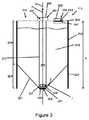
図3は、構築材料リザーバ210を含む構築材料供給源容器114のような、構築材料供給源容器の別の詳細な例を示す。リザーバ210は、少なくとも部分的にフレキシブルとすることができ、幾つかの例においてフレキシブルバッグとすることができる。容器214は、例えばリザーバ210の周りに補強構造体223を設けられ得る。リザーバ210の少なくとも一部は、補強構造体223に取り付けられる又は付着され得る。補強構造体223は、例えば、厚紙(段ボール)から形成されたボックスからなることができる。フレキシブルバッグは、当該ボックス内に収まり及び当該ボックスにより支持されるように構成され得る。構築材料供給源容器は、使い捨てできる又は交換可能な構成要素を含むことができる。導電性成形プラスチックから形成され得る出口構造体は、ボックス及び/又はバッグに結合され得る。ボックスは、例えば出口構造体が取り外された場合に、折り畳むことができる。 FIG. 3 illustrates another detailed example of a build material source container, such as build
リザーバ210は、少なくとも1つの比較的直立した壁からなる上方部、及びじょうご状形状の下方部を含むことができる。直立した上方部の少なくとも1つの側壁は、容器114a、114bの直立状態で折り畳まれていないで満杯の状態で実質的に垂直に延びることができる。異なる例において、少なくとも1つの実質的に垂直な側壁は、上面図(図示せず)から見られる場合に、少なくとも1つの丸みを帯びた壁とすることができ、又は直線または丸みを帯びた角を有する長方形を形成することができる。この例において、大量の構築材料の貯蔵を容易にするために4つの側壁を有する長方形バージョンが説明される。
供給源容器114は、上部205及び下部207を含み、上部205は、収束していない、例えば、実質的に直立した壁219を含み、容器114の高さHの大部分に及ぶ。容器114は、構築材料が上面215からリザーバ210を出ることを可能にするために上面に出口開口231を有する出口構造体234を含む。出口構造体234は、外部接続ユニットに接続するためのアダプター208を含むことができ、外部接続ユニットは、真空源またはポンプのような圧力ユニットとすることができ、真空吸引によりリザーバ210から構築材料を取り出すことが容易にされる。 The
図示された例において、下部207は、重力および/または圧力ユニットにより生成された圧力の影響下でリザーバ210の底部209における中央収集領域の方へ構築材料を案内するためにじょうご形にされる。じょうごは、傾斜した収束する壁221により形成される。 In the illustrated example, the
容器114の出口構造体234は、リザーバ210の底部209から構築材料を収集するためにリザーバ210の上面215の近くの出口開口231から底部209まで延びる内部長手方向収集ユニット217を含む。収集ユニット217は、出口構造体234の固定または取り外し可能部分を形成することができる。収集ユニット217は、底部209における収集領域から構築材料を収集することができ、上面215における出口開口231を介して構築材料を外へ案内することができる。一例において、収集ユニット217は、少なくとも部分的に管状である。管状ユニットは、上面215の出口開口231からリザーバ210の中央底部209まで延びることができる。収集ユニット217は、収束していない、例えば、直立した上部205に沿ってじょうご207へ延び、じょうご207の底部209から構築材料を収集する。幾つかの例において、収集ユニット217は、剛性管またはフレキシブルホースを含むことができる。 The
一例において、収集ユニット217は、その管を介した真空吸引を容易にすることができる。係る例において、出口構造体234のアダプター部分208は、積層造形装置の圧力ユニットに接続するように構成され、その結果、圧力ユニットが出口構造体234に接続されてオンにされる場合、構築材料(及び空気)の流れが上向き方向Fで管を通じて確立される。 In one example, the
一例において、容器114は、真空吸引中にリザーバ210へ空気を放出することを容易するために、出口構造体234に隣接して、上部壁215にスループット構造体235を含む。別の例において、リザーバ210は、少なくとも部分的にフレキシブルであり、それにより前記真空吸引中、特定の壁部分が内側へ撓む及び/又は振動することができる。更なる例において、圧力ユニットは、例えばリザーバ210に充填する際に、リザーバ210に正圧を印加することができる。特定の例において、フレキシブルな壁は、係る正圧の下で好都合に曲がる及び/又は振動することができ、構築材料の適切な充填および混合を容易にする。 In one example, the
一例において、リザーバ210は、約5から60リットル、例えば約15から45リットルの内容積を有し、管は、約40から65cmの、出口開口231から遠位末端241の長さを有することができる。管は、約10から70mm、例えば約25から60mmの直径を有することができる。 In one example, the
構築材料は、管の遠位末端部分237において管に入ることができる。末端部分237は、底部209から構築材料を抜き出すために底部209の近くに延びる。更なる例において、末端部分237は底部209に接触し、それにより管は、例えば補強構造体223に加えて、容器214に追加の構造的補強をもたらすことができる。末端部分237は、構築材料が入ることができる少なくとも1つの吸引開口239を含む。一例において、末端部分237は、複数の係る吸引開口239が延びるネジ部または表面を含む。一例において、末端部分237は、不要な粒子が収集システムに供給されることを制限するためのフィルタを含むことができる。 The build material can enter the tube at the
一例において、管の末端部分237は、横方向吸引開口239を含み、それにより動作中、構築材料は少なくとも部分的に横方向Lにおいて管233に入る。末端部分237は更に、キャップ又はネジ部のような遠位末端構造体241を含むことができる。一例において、遠位末端構造体241はリザーバの底部209に係合する。横方向開口239は、遠位末端構造体241の上に少なくとも部分的に延び、その結果、動作中、構築材料が、遠位末端構造体241の上で横方向に管233へ入る。遠位末端構造体241は、底部壁部分が吸引開口239を閉塞することを防止することができる。 In one example, the
構築材料供給源容器内での構築材料の粒子状物質の移動中、静電気が粒子状物質間の連続的な摩擦力に起因して生じる可能性がある。また、摩擦力は、粒子状物質と構築材料供給源容器の構造体との間にも発生する可能性がある。係る考慮事項は、MMS106の他の所の粒子状物質の移動にも適用され得る。構築材料供給源容器114に関連して具体的な開示がなされているが、容器の部分を導電性材料から形成する同じ開示された手法が、MMS106の実質的に任意の部分に適用され得る。特に、粉末が高速で移動し、摩擦に起因した静電気の発生が起きると考えられるMMS106の任意の部分は、導電性材料からそのように形成され得る。また、そのような部分は、例えば出口構造体234又は接続ユニット202内のような、任意の粉体流案内構成要素とすることができる。導電性材料から形成されたMMS106の係る部分または案内構成要素は、放電経路を提供するためのアースに接続可能とすることができる。 During the movement of the build material particulates within the build material source container, static electricity can occur due to the continuous frictional forces between the particulates. Frictional forces can also occur between the particulate matter and the structure of the build material source container. Such considerations may also apply to the transfer of particulate matter elsewhere in
一例において、粉体流構成要素に沿って容器を接地させることができる導電性材料は、管233の一部であり、又は管233に沿って延在する。幾つかの例において、これは、入口開口の近くからアパーチャ206までである。適切な導電性材料は、導電粒子を有するプラスチック化合物、金属または金属合金、コーティング、薄膜(フィルム)、配線、コイルなどを含む。導電性材料を有する構築材料容器は、容易に交換可能であるように設計され得る。 In one example, a conductive material that can ground the container along the powder flow component is part of or extends along
図4及び図5は、例示的な構築材料容器の例示的な出口構造体234、及びMMS106に対する、圧力ユニット259のような関連接続ユニット202を介した前方接続のアダプター部分の図を示す。図4は、例示的な出口構造体234の上面線図を示す。図5は、例示的な出口構造体234と関連付けられるべき例示的な圧力ユニット259の端部部分の部分断面側線図を示す。 4 and 5 show views of an
例において、供給源容器114の出口構造体234は、接続ユニット202に接続するためのアダプター208を含む。出口構造体234は、例えばアダプター208の底部からリザーバ内へとリザーバの底部209まで突出する出口管233(図3に示される)を介して、リザーバの内部へのアクセスを与えるために、その中央に出口開口231を含む。 In the example, the
例示された例において、アダプター208は管233より幅広い。アダプター208は、アダプター208のインターフェース面263の外縁261に沿って少なくとも1つの直立壁257を含む。直立壁257は周囲壁とすることができる。直立壁257は、対応する圧力ユニット259を相互接続へと案内する働きをすることができる。 In the illustrated example, the
管233は、圧力突出部273を出口構造体234へと案内することができるので、第1の案内機構の役目をすることができる。直立壁257は、圧力ユニットアダプター275を出口構造体234へと案内することができるので、第2の案内機構の役目をすることができる。 The
直立壁257は、空気/構築材料の流れ方向Aに突出することができる。直立壁257は、例えば圧力ユニット259のアダプター275と或る程度の摩擦嵌合を提供するために、対応する圧力ユニット259に適合することができる。出口構造体のアダプター208は更に、インターフェース面263を含む。インターフェース面263は、環状とすることができ、出口開口231と直立壁257との間で、空気/構築材料の流れ方向Aに垂直に出口開口231の周囲に延在することができる。幾つかのインターフェース要素がインターフェース面263に設けられ得る。一例において、第3の案内特徴要素として役立つことができるデジタル相互接続ポケット268のような、特定の更なる案内特徴要素が、インターフェース面263に設けられて、圧力ユニットを出口構造体234に案内および結合する際に支援することができる。 The
出口アダプター208は、インターフェース面263に少なくとも1つの相互接続特徴要素255を含むことができる。相互接続特徴要素は磁気的とすることができる。磁気相互接続特徴要素255は、外部接続ユニットのアダプター275の対応する磁気要素に引きつけるために、磁性金属または磁石のような少なくとも1つの磁気要素を含む。相互接続特徴要素255は、環状インターフェース面263に露出され得る及び/又は環状インターフェース面263から突出することができる。インターフェース面263上の磁気相互接続255は、ひとたびその個々の磁気要素283が出口アダプター208の磁気相互接続255に接近すると、接続ユニットアダプター275を引き寄せ、その結果、最終的な相互接続の動きが自動的に行われる。磁気案内特徴要素255は、突出部273を最終的な相互接続した状態へ引き寄せることができ、それにより磁気案内特徴要素255の引力は、出口構造体234及び突出部273が適切に接続されたというフィードバックを操作者に提供することができる。また、磁力は、相互接続された突出部273及び出口構造体234を保持することに役立つことができる。突出部273とアダプター208との間の相互接続は、圧力ユニットとしての接続ユニット202がオンにされた際の真空吸引力により更に維持され得る。 The
出口構造体234の他の案内特徴要素は、突出部、レール、ノッチなど、例えば相互接続する構造体のオス要素またはメス要素を含むことができる。更に、クリック止めフィンガ、ラッチ、ノッチ、摩擦嵌合要素などのような保持特徴要素が設けられて、圧力ユニットに掛止することができ、その結果、アダプター及び圧力ユニットは、圧力ユニットがオンにされていない場合でも、例えば引っ掛ける、掛止する(ラッチで止める)、摩擦などにより結合された状態を維持する。従って、相互接続特徴要素255は、堅牢で使いやすい相互接続を容易にすることができ、例えば埃っぽい環境でうまく機能することができる。 Other guiding features of the
出口アダプター208は更に、センサ起動要素265を含むことができる。一例において、起動要素265は、接続ユニット202のセンサデバイスを例えば光学的に又は機械的に活性化するために、インターフェース面263から突出する。アダプター208は更に、データインターフェース267を含む。データインターフェースは、インターフェース面263に、例えばインターフェース面263のポケット268に設けられ得る。データインターフェース267自体は、メモリチップ、マイクロコントローラ、集積回路、スマートチップなどのパッドを接続することにより形成され得る。データインターフェース267は、接続ユニット202のアダプター275に設けられる対応するデータインターフェース287に接続することができる。データインターフェースは、構築材料供給源容器の導電性部分から電気絶縁され得る。例えば、インターフェース面263は、アダプターの絶縁プラスチック部分上に形成され得る。 The
出口構造体234は更に、出口開口231を覆うためのバルブ269を含むことができる。バルブ269は、管233の内部に延びることができる。バルブ269は、圧力ユニット259が接続されていない場合に、構築材料(例えば、粉塵)がリザーバから出ることを阻止することができる。一例において、バルブ269は、(i)接続ユニット202による出口構造体234の上への十分な圧力、及び(ii)出口構造体234に挿入されて、バルブ269を開くように押し動かす外部アダプター管などの少なくとも1つにより開くことができる。例示された例において、バルブ269は、例えばそれぞれが円の四分の一を形成し且つ管233の内壁から突出する4つのフレキシブルな薄膜からなるフレキシブル薄膜バルブである。薄膜バルブ269Bは、突出部273の挿入により開き、突出部273が出口構造体234から引き出される際に閉じる位置に戻るように曲がる。 The
出口アダプター208は更に、上向きの方向において管233の内壁から突出する突出フィンガ271を含むことができる。図示された例において、フィンガ271は、第1に内壁から離れて突出し、接続ユニット202の対応するバルブを押し開くために出口開口231に向かって上方に向いている。 The
突出部273は管状とすることができ、突出部273が真空吸引方向Aと反対の挿入方向Iにおいて管233へ滑り込むことを容易にするために、容器114の出口管233の内径に対応する外壁径を有する。突出部273は、管233の上部へ途中まで挿入するために、管233より短い。突出部273は、リザーバ203から構築材料を吸い込むために管233に嵌まることができると同時に、突出部273の外壁と管233の内壁との間で構築材料が固まることを阻止することができる。一例において、摩擦嵌合が突出部273と管233との間に確立され得る。 The
バルブ279は、例えば圧力ユニット(接続ユニット)202がオフにされる際に、突出部273を閉じるために突出部273に設けられ得る。閉じたバルブ279は、真空がオフにされた際に構築材料が突出部273から出ることを阻止することができる。図示された例において、突出部バルブ279は、円形のスイベルバルブであり、その外径は、突出部の内径に一致する。バルブ279は、突出部273の遠位末端における入口開口281の近くに配置され得る。出口管233のフィンガ271が、管233の中の突出部279の挿入の所でバルブ279に係合し、それによりバルブ279を押し開き、その結果、構築材料が自由に突出部273へ流入することができる。同時に、出口管233の他のバルブ269、269Bが突出部273により開かれる。 The
先に詳述されたように、圧力ユニット259のアダプター275は、突出部273と出口構造体234との間の適切な相互接続を容易にするために、出口アダプター208の関連する磁気相互接続特徴要素255を引き寄せるために磁性を持つことができる少なくとも1つの相互接続特徴要素283を含むことができる。前述のように、圧力ユニット259がオンにされる場合、真空自体が突出部273及び出口構造体234を相互接続された状態に保持することができる。アダプター275は、出口アダプター251の突出部265を検知するセンサ回路285を含むことができる。センサ回路285は、例えば圧力ユニット259をオンにする及び/又は圧力ユニット259の内部の更なる内部バルブユニットを開くために、適切な相互接続が確立された圧力ユニット259又は積層造形装置のコントローラ又はサーボに信号を送ることができる。それにより、圧力ユニット259は、構築材料容器114との適切な機械的および電気的相互接続の間にオンにされる。圧力ユニットアダプター275は更に、出口アダプター208の容器データインターフェース267と相互接続することができるホストデータインターフェース287を含むことができる。一例において、データインターフェース287は、容器データインターフェース267から受け取られた際に、圧力ユニット259又は積層造形装置のコントローラに対する認証データ及び構築材料データを含むデータの転送(伝達)を行うことができる。コントローラは、読み出しデータに基づいて容器を認証することができる。一例において、圧力ユニット259は、認証が確立された場合にオンにされる。更なる例において、センサ係合突出部265、及び認証データを含むデジタルインターフェース267は、圧力ユニット259をオンにするために適切に相互接続される必要がある。 As described in detail above, the
別の例において、磁気相互接続特徴要素255は、アダプター208を供給源容器の残りの部分、又は出口構造体234に位置決めする又は固定するためのネジのような固定要素である。一例において、固定要素255は、圧力ユニット259の磁気要素に接続されることができない。異なる例において、ネジ255は、(i)固定要素、(ii)磁気案内特徴要素、及び(iii)接地接続、又はそれ以上の少なくとも1つとして働くことができる。固定および/または磁気要素255が接地を介して放電することができる場合、圧力ユニット259の突出部273は、例えば構築材料(例えば、粉末)が流れている間に容器の出口構造体234を放電するために接地に接続される対応する導電および/または磁気相互接続特徴要素283を有することができる。 In another example, the
構築材料収集管233は、少なくとも1つの構築材料真空吸引開口239を有するその遠位末端において末端部分237を含むことができる。動作中、管233は、リザーバの底部から構築材料を収集するために構築材料リザーバ内に延びることができる。管233は、外部圧力ユニット259に接続するためにその近位末端においてアダプター208に接続される。図示された例において、収集管233は更に、空気チャネル(図示せず)を含む。空気チャネルは、管233の長さに沿って延びることができる。空気チャネルは、周囲空気と連絡することができる近位開口、及びリザーバの内側、例えばリザーバ内の底部構築材料収集領域の近くと連絡することができる遠位開口を含む。空気チャネルは、底部209から構築材料を容易に収集することを促進することができ、例えば底部209の近くのガス抜きに役立つ。 The build
空気チャネルは、管233に一体化され得る。一例において、1つ又は複数の空気チャネルは、管233の真空チャネルに隣接して、管233の真空チャネルに平行に延びる。別の例において、空気チャネル253は、管233の真空チャネルに同心に、即ち真空チャネルの少なくとも一部の周りに延び、それにより管233は、中心軸の回りに2つの同心の管状壁を含む。 The air channel can be integrated into the
出口構造体234の内壁は、容器114から圧力ユニット259まで構築材料を案内することができる。例えば、構築材料の真空吸引中、構築材料は、容器114から遠位入口開口239、管233の内壁、及び開口231及びアダプター208の円筒形内壁に沿って流れる。一例において、構築材料は、管233から圧力ユニット259の突出部273へ直接的に流れ、それによりアダプター208に直接的に接触しない。構築材料が収集イベント中に流れる容器114のこれら構成要素は、接地するための導電性部分を含む。一例において、当該部分、例えば遠位末端部分237、管233及び/又はアダプター208は、少なくとも部分的な導電性材料から形成される。少なくとも部分的な導電性材料は、導電粒子または金属を含むプラスチック化合物とすることができる。金属は、アルミニウム、又はアルミニウム及び/又は他の金属を含む任意の合金とすることができる。他の例において、構築材料が流れる前記構成要素に、コーティングが塗布され得る。更なる例において、出口管233は導電性にされ、それにより接地接続が、相互接続の間に、管233と外部管突出部273との間に確立される。 The inner wall of the
更なる例において、アダプター208は、少なくとも部分的に前記導電性材料から作成され、その結果、構築材料が管233を流れる際に管233から受け取ったような電荷が、アダプター208により導電され得る。アダプター208は、圧力ユニット突出部273に接続することにより放電することができる。更なる例において、圧力ユニット259の接地接続に対する接続は、相互接続特徴要素455のようなアダプター208の更なる導電構成要素により更に容易にされ得る。 In a further example, the
図2A及び図2Bに戻って参照すると、導電性放電経路が、図5の圧力ユニット259のような接続ユニット202の導電要素を介して、MMS106の接地部分まで提供され得る。幾つかの例において、接続ユニット202は、接続ユニット202の管体212の長さに沿って第1の端部から第2の端部まで延び且つユニット202の静電放電経路を提供する細長い導体204を含むことができる。しかしながら、更なる例において、導体204は、管体212に沿って途中まで延びることができる。細長い導体は、金属ワイヤとすることができ、管体212内に少なくとも部分的に入れられることができる。導体204は、少なくとも部分的に又は実質的に管体の材料内に入れられることができ、その結果、導体204は接続ユニット202内で絶縁される。ユニット202の本体は、非導電性材料からなることができる。代案として、導体204は、外面的に、例えばユニット202の周りに螺旋状に設けられ得る。 Referring back to FIGS. 2A and 2B, a conductive discharge path may be provided through the conductive elements of the
接続ユニット202の第1及び第2の端部は、導体204を電気接地するために導体に電気接続される接続部を含む。一例において、接続ワイヤが、管202の第1の端部において導体204の接続部上へ圧着されるが、理解されるように他の接続技術が使用され得る。導体204と接続ワイヤとの間の接続部は、電気絶縁被覆で覆われ得る。 The first and second ends of the
幾つかの例において、新しい構築材料の供給源容器114、接続ユニット202及びアダプター208のそれぞれの少なくとも一部は、導電性材料から形成される。各部分を導電性材料から構築することは、製造のコストと難しさを低減することができる。更なる例において、導電性材料の使用は、移動する粉末材料に接触することに起因して摩擦が生じると思われるこれら部分(例えば、供給源容器114、アダプター208又は接続ユニット202の部分)が導電性材料から形成され得ることに制限され得る。係る例において、アダプター及び接続ユニットのような導電構成要素が電気結合されるので、別個のインタコネクタ(図4及び図5に示されるような)は使用されなくてもよい。しかしながら、インタコネクタは、上述されたように、接続を改善するために、更に使用され得る。代案として又は更に、導電性材料は、図3の管233により示されたように、アダプター208から供給源容器114へと内側に延びる管部分の内部の少なくとも一部または全長を構成することができる。更に、接続ユニット202の管体212の少なくとも一部は、導電性材料からなることができる。これら例において、新しい構築材料の供給源容器114の残りの部分は、代替の材料から構築され得る。係る代替の材料は、材料のコスト又は関連特性に基づいて選択され得る。 In some examples, at least a portion of each of the new build
一例において、導電性材料は、アダプター208を覆う又はアダプター208に付着される導電性薄膜(フィルム)とすることができる。必要に応じて、アダプター208の特定の表面がそのように覆われることができ、例えば、これら表面(主に内面)は、高速に移動する構築材料に接触する。従って、上述されたように供給源容器114の係る部分を覆うための導電性材料の部分は、導電性薄膜からなることができる。代案として、導電性材料の係る部分は、コーティングとみなされ得る。 In one example, the conductive material can be a conductive film that covers or is attached to the
一例において、当該部分の少なくとも1つに使用される導電性材料は、導電性プラスチックとすることができる。導電性プラスチックは、導電性粒子を含むプラスチック化合物とすることができる。更なる例は、これら部分の少なくとも1つに金属を使用することを含むことができる。特定のプラスチックは、他の導電性材料(例えば、金属)に比べて軽くて安価であるかもしれない。適切な導電性プラスチック材料は、ポリカーボネート又はポリプロピレン、或いは炭素、ニッケル、ステンレス鋼または黒鉛フィラーのような添加剤を添加したプラスチックを含む。代案として、幾つかの例において、使用されるフィラーは、炭素繊維、ナノ繊維または金属繊維である。一般に、適切な材料は、導電性であり且つ容器のその特定部分に適切な機械的性質を有するものである。出口構造体の部分を形成するための例示的な導電性材料は、炭素または代替の導電性添加剤がプラスチックへ混合されている成形プラスチック構成要素を含む。導電性材料は、構築材料の流路に面する出口構造体の部分に制限されることができるか、又は出口構造体の全部を実質的に構成する又は覆うことができる。例示的な導電性材料は、1×103から1×105Ω/m2の表面抵抗を有する材料を含むことができる。更なる例において、1×105から1×109Ω/m2の表面抵抗を有する散逸材料が使用され得る。更なる例において、1×109から1×1012Ω/m2の表面抵抗を有する適切な静電防止材料が使用され得る。In one example, the conductive material used for at least one of the portions can be a conductive plastic. The conductive plastic can be a plastic compound containing conductive particles. Further examples can include using metal for at least one of these portions. Certain plastics may be lighter and cheaper than other conductive materials (eg, metals). Suitable conductive plastic materials include polycarbonate or polypropylene, or plastics with additives such as carbon, nickel, stainless steel or graphite fillers. Alternatively, in some examples, the filler used is carbon fiber, nanofiber or metal fiber. In general, suitable materials are those that are electrically conductive and have the appropriate mechanical properties for that particular portion of the container. Exemplary conductive materials for forming part of the outlet structure include molded plastic components in which carbon or alternative conductive additives are mixed into the plastic. The conductive material can be limited to the portion of the outlet structure that faces the flow path of the build material, or can substantially constitute or cover all of the outlet structure. Exemplary conductive materials can include materials having a surface resistance of 1×10³ to 1×10⁵ Ω/m2 . In a further example, a dissipative material with a surface resistance of 1×10⁵ to 1×10⁹ Ω/m2 can be used. In a further example, a suitable antistatic material having a surface resistance of 1×10⁹ to 1×10¹² Ω/m2 can be used.
別の例において、導電性材料は金属とすることができる。例えば、管233は、少なくとも部分的にアルミニウムから、例えば押し出しアルミニウムから作成され得る。 In another example, the conductive material can be a metal. For example, the
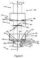
図6A〜図6Bは、図5に示されたような圧力ユニット259のような、接続ユニット202からMMS106まで、一例において新しい構築材料の供給源容器の出口構造体234までの接続、及び形成された放電経路のより詳細な例を示す。 6A-6B show the connection and formation of the
接続ユニット202を出口構造体234に接続するために、接続ユニット202の管状突出部273は、接続ユニットアダプター275の底部が供給源容器の出口アダプター208の上側に隣接して配置されるまで、容器ユニット114の出口アダプター208へ挿入される。この配置により、図5に詳記されるように突出部273が管233の中に収まることを可能にし、この場合、幾つかの例において、摩擦嵌合が確立され得る。 To connect the
各アダプター208、275は、供給源容器114のアダプター208に接続ユニットアダプター275を固定する働きをする、多数の磁気要素255、283又は他のタイプのインタコネクタを含むことができる。これらインタコネクタは、各アダプターの円筒形粉体流チャネルの周りの各アダプター208、275の環状インターフェース面に露出されるか、又は当該環状インターフェース面から部分的に突出することができる。係るインタコネクタ283は、アダプター208を管に磁気的に結合する働きをし、且つ電気接続としての機能を果たす働きをする。相互接続された状態において、インタコネクタは、供給源容器114の導電金属部分間に連続した導電経路を提供し、その結果、導電性材料の対策が供給源容器アダプター208及び出口管233の少なくとも一部内に含まれ、この場合、当該経路は、MMS106の接地された部分まで延びている。接続要素が特定距離の範囲内に持って来られる場合、それらの間の磁力が、矢印により示されるように、相互接続部分283を接触させて当該接続を固定する。この磁力は、接続ユニット202と構築材料容器114との間の接続を固定し、ユーザに対して安全で好都合なコネクタの挿入方法を提供する。この例において、磁気インタコネクタは、保持力に加えて、接地接触を提供する。 Each
幾つかの例において、使用されるインタコネクタ要素は、使用するのに安価で好都合なネジ又は磁石のような金属固定要素とすることができる。しかしながら、理解されるように、適切な磁気的および電気的接続を提供する任意の適切な材料または要素が使用され得る。更なる例において、係る接続は、図5に示されたようなデータインターフェース287を介して提供され得る。理解されるように、このような場合、データインターフェース287は、アダプター又は出口構造体の導電性部分から完全に絶縁されない。更に理解されるように、場合によっては、アダプターの少なくとも一部が導電性材料から形成されて接続ユニットに対する上り接続が接続ユニットの導電性部分と電気接触する場合、別個のインタコネクタ要素が設けられなくてもよい。 In some examples, the interconnector elements used can be metal fastening elements such as screws or magnets that are inexpensive and convenient to use. However, as will be appreciated, any suitable material or element that provides suitable magnetic and electrical connections may be used. In a further example, such a connection may be provided via the
従って、新しい構築材料の供給源容器114のための接地接続は、接続ユニット202と供給源容器114の出口構造体234との間の接続を介して行われる。一例において、導電性経路は、少なくとも接続ユニットアダプター275及び供給源容器の出口アダプター208の導電性材料から、例えばアダプター208及び275のそれぞれ内に含まれる少なくとも1つの相互接続要素を介して、MMS106の方へ外部管212を介して延びる導通ワイヤ(図2A及び図2Bに示されたような)の先へ形成される。しかしながら、当業者により理解されるように、供給源容器を導通ワイヤに又は管の他の導電性面に電気接続するための多くの代案が使用され得る。幾つかの例において、MMS106に構築材料を供給するための供給源容器214に接続ユニット202の突出部273を接続する動作は、ユーザにより留意されるべき更なる動作なしで、電気接続を形成する働きをする。幾つかの例において、接続ユニット202及び出口構造体234は、例えば突出部273の適切な回転を生じる磁石の作用により、自動的に電気接続を位置合わせする働きをする。幾つかの例において、供給源容器214の導電性部分は、電気接続が内側管および外側管217、212をそれぞれ結合する際に常に行われることを確実にするために実質的に広範囲に及ぶ。かくして、連続した静電放電経路が、供給源容器114の導電性材料部分を介してMMS106の接地部分まで設けられる。Accordingly, the ground connection for the new build
接続ユニット202のアダプター275は、容器114に磁気的に所定位置に固定される際にハンドルとみなされ得る。ユーザは、新しい構築材料の供給源容器114の出口構造体234から離れる方向にハンドルを移動させることにより、いつでも接続を外すことができる。これは、供給部の吸引システムにおける電気接地を確実にするための安価で安全で堅牢で使いやすい方法を提供する。 The
更なる例において、3DプリンタのMMS106は、構築材料供給源容器であって、その供給源容器が、構築材料を保持するための実質的に密閉された空間を画定する壁、及び構築材料が進入および退出するためのアパーチャを有する構築材料供給源容器と、接続ユニットとを含むことができ、接続ユニットの第1の端部は、供給源容器から粉末状材料を移送するために供給源容器のアパーチャに接続可能である。材料供給源容器の少なくとも一部は、導電性材料を含むことができ、接続ユニットは、構築材料供給源容器を材料管理ステーションの接地部分に電気接続するための導電性部分を含む。接続ユニットは、構築材料を移送するための管状本体を含むことができる。接続ユニットの導電性部分は、管体内に少なくとも部分的に入れられる(封入される)細長い導体を含むことができる。 In a further example, the
更なる例において、MMS106は、管体の第1の端部に位置し、当該管を接地するための導体に電気接続されている第1の接続端子と、粉末状材料供給タンクから接地までの前方への接続を提供するための、当該管の第2の端部に位置する第2の接続端子とを更に含むことができる。In a further example, the
本明細書(あらゆる添付の請求項、要約および図面を含む)に開示された特徴要素の全ては、係る特徴要素の少なくとも幾つかが相互に排他的である組み合わせを除いて、任意の組み合わせで組み合わされ得る。 All of the features disclosed in this specification (including any appended claims, abstracts and drawings) may be combined in any combination, except combinations where at least some of such features are mutually exclusive. Can be done.
本明細書(あらゆる添付の請求項、要約および図面を含む)に開示された各特徴要素は、明示的に別段の定めをした場合を除き、同じ、等価の又は類似の目的に役立つ代替の特徴要素により置き換えられ得る。かくして、明示的に別段の定めをした場合を除き、開示された各特徴要素は、包括的な一組の等価または類似の特徴要素の一例である。 Each feature disclosed in this specification (including any accompanying claims, abstracts, and drawings) is intended to be an alternative feature serving the same, equivalent, or similar purpose, unless expressly stated otherwise. Can be replaced by an element. Thus, unless expressly stated otherwise, each feature disclosed is an example of a comprehensive set of equivalent or similar features.
本教示は、何らかの上述の例の細部に制限されない。本明細書(あらゆる添付の請求項、要約および図面を含む)に開示された特徴要素の何らかの新規な組み合わせが、企図され得る。特許請求の範囲は、上述の例を単にカバーすると解釈されるべきでなく、任意の変形態様も特許請求の範囲の範囲に入る。 The present teachings are not limited to the details of any of the above examples. Any novel combination of features disclosed in this specification (including any appended claims, abstract and drawings) can be contemplated. The claims should not be construed as merely covering the above examples, and any variation is within the scope of the claims.
Claims (21)
Translated fromJapanese構築材料を保持するための実質的に密閉された空間を形成し、非導電性材料から形成されて、上面および底部を有する外側補強構造体と、
構築材料が前記実質的に密閉された空間に対して進入および退出するためのアパーチャを有する出口構造体であって、前記出口構造体は、導電性材料から形成され、前記構築材料供給源容器内で生じた静電気を放電するために接地に接続可能であり、前記出口構造体は、空気圧によって前記構築材料供給源容器から構築材料を取り出すための接続ユニットに接続可能であり、前記外側補強構造体の上面に位置する、出口構造体とを含み、
前記構築材料供給源容器は、導電性材料を含む内側管を受容するように構成され、前記内側管が、前記実質的に密閉された空間の中へ、前記出口構造体の前記アパーチャから前記外側補強構造体の前記底部まで延び、前記出口構造体と電気連絡するようになっている、構築材料供給源容器。A building material source container for use in a material management station of a three-dimensional (3D) printer,
Forming a substantially enclosed space for holdingbuildingmaterial, formed from a non-conductive material, an outer reinforcing structure having a top surface and a bottom,
A outlet structure building material has an aperture for entry and exitto the substantially closedspace,the outlet structure is formed of a conductivematerial, before SL build material source containerRi connectable der to ground to discharge static electricity generated in theinner, the outlet structure is connectable to a connection unit for taking out the build material from the build material source container pneumatically, said outer reinforcing An outlet structure located on the upper surface of the structure,
The build material source container is configured to receive an inner tube containing an electrically conductive material, the inner tube into the substantially enclosed space from the aperture of the outlet structure to the outer side. A building material source containerextending to the bottom of a reinforcement structure and adapted to be in electrical communication with the outlet structure .
前記データインターフェースが、前記出口構造体から絶縁されている、請求項2〜4、請求項2に直接的に又は間接的に従属する請求項5、及び請求項6〜7の何れか1項に記載の構築材料供給源容器。The adapter further comprises a data interface for connecting to a corresponding data interface provided inthe adapter of theconnection unit ,
8. A data interface according to any one of claims2-4, claim 5 directly or indirectly dependent on claim 2, and any of claims 6-7, wherein the data interface is insulated from theoutlet structure. The described build material source container.
構築材料を保持するための実質的に密閉された空間を形成し、非導電性材料から形成されて、上面および底部を有する外側補強構造体と、An outer stiffening structure forming a substantially enclosed space for holding build material, formed from a non-conductive material, having a top surface and a bottom portion;
構築材料が前記実質的に密閉された空間に対して進入および退出するためのアパーチャを有する出口構造体であって、前記出口構造体は、導電性材料から形成され、前記構築材料供給源容器内で生じた静電気を放電するために接地に接続可能であり、前記出口構造体は、空気圧によって前記供給源容器から構築材料を取り出すための接続ユニットに接続可能であり、前記外側補強構造体の上面に位置する、出口構造体と、An exit structure having an aperture for a build material to enter and exit the substantially enclosed space, the exit structure being formed from a conductive material, within the build material source container. Is connectable to ground to discharge static electricity generated in the outlet structure, the outlet structure is connectable to a connection unit for removing build material from the source container by air pressure, and the upper surface of the outer reinforcing structure is connected. An exit structure located at
前記実質的に密閉された空間の中へ、前記出口構造体の前記アパーチャから前記外側補強構造体の前記底部まで延び、前記出口構造体と電気連絡する導電性材料を含む内側管とを含む、構築材料供給源容器。An inner tube extending into the substantially enclosed space from the aperture of the outlet structure to the bottom of the outer reinforcing structure and including an electrically conductive material in electrical communication with the outlet structure. Building material supply container.
前記アダプターは、前記接続ユニットに接続された場合に、前記内側管を含む静電放電経路の一部を形成し、The adapter forms a part of an electrostatic discharge path including the inner tube when connected to the connection unit,
インタコネクタが、前記アダプターを前記構築材料供給源容器に更に固定し、An interconnector further secures the adapter to the build material source container,
前記インタコネクタが、前記アダプターを前記接続ユニットの前記第1の端部部分に接続する、請求項15に記載の構築材料供給源容器。16. The build material source container of claim 15, wherein the interconnector connects the adapter to the first end portion of the connection unit.
前記第1及び第2の導電インタコネクタの少なくとも一方が、前記接続ユニットの前記第1の端部部分に前記アダプターを接続するために前記第1及び第2の導電インタコネクタの他方に磁気的に結合するために磁性を持っている、請求項16、17、及び請求項16に直接的に又は間接的に従属する請求項18の何れか1項に記載の構築材料供給源容器。At least one of the first and second conductive interconnectors is magnetically coupled to the other of the first and second conductive interconnectors for connecting the adapter to the first end portion of the connection unit. 19. A build material source container according to any one of claims 16, 17 and claim 18 directly or indirectly dependent on claim 16 having magnetic properties for binding.
Applications Claiming Priority (1)
| Application Number | Priority Date | Filing Date | Title |
|---|---|---|---|
| PCT/EP2016/060661WO2017194112A1 (en) | 2016-05-12 | 2016-05-12 | A build material source container |
Publications (2)
| Publication Number | Publication Date |
|---|---|
| JP2019515811A JP2019515811A (en) | 2019-06-13 |
| JP6740358B2true JP6740358B2 (en) | 2020-08-12 |
Family
ID=55967285
Family Applications (1)
| Application Number | Title | Priority Date | Filing Date |
|---|---|---|---|
| JP2018539878AActiveJP6740358B2 (en) | 2016-05-12 | 2016-05-12 | Building material supply container |
Country Status (7)
| Country | Link |
|---|---|
| US (1) | US10723076B2 (en) |
| EP (1) | EP3455051B1 (en) |
| JP (1) | JP6740358B2 (en) |
| KR (2) | KR20180099806A (en) |
| CN (1) | CN108602256B (en) |
| BR (1) | BR112018015091A2 (en) |
| WO (1) | WO2017194112A1 (en) |
Families Citing this family (10)
| Publication number | Priority date | Publication date | Assignee | Title |
|---|---|---|---|---|
| CN108770350B (en)* | 2016-05-12 | 2021-04-16 | 惠普发展公司,有限责任合伙企业 | Data unit for building material identification in additive manufacturing |
| EP3330062B1 (en)* | 2016-11-30 | 2022-02-09 | Ivoclar Vivadent AG | Material feeding device for a stereolithography apparatus |
| CN109834934A (en)* | 2017-11-29 | 2019-06-04 | 香港纺织及成衣研发中心有限公司 | Horizontal for 3D printer controls print system of interlocking |
| US20200139695A1 (en)* | 2018-03-07 | 2020-05-07 | Hewlett-Packard Development Company, L.P | Supply station for object post-processing |
| US11534963B2 (en)* | 2018-03-27 | 2022-12-27 | Freemelt Ab | Radiation method for additive manufacturing |
| EP3820698A1 (en)* | 2018-08-30 | 2021-05-19 | Hewlett-Packard Development Company, L.P. | Additive manufacturing device with mating interface |
| CN111515339B (en)* | 2020-01-16 | 2021-08-17 | 共享智能铸造产业创新中心有限公司 | 3D printing equipment |
| JP2022017003A (en)* | 2020-07-13 | 2022-01-25 | 株式会社リコー | Three-dimensional molding device |
| DE102021119306A1 (en)* | 2021-07-26 | 2023-01-26 | One Click Metal GmbH | Connection device for accommodating a cartridge container and for positioning in a system for the production of three-dimensional components |
| US20230226763A1 (en)* | 2022-01-19 | 2023-07-20 | Fermi Research Alliance, Llc | Additive manufacturing platform system |
Family Cites Families (22)
| Publication number | Priority date | Publication date | Assignee | Title |
|---|---|---|---|---|
| US3580983A (en) | 1969-12-03 | 1971-05-25 | Nat Catheter Corp | Conductive line tube |
| US3640276A (en)* | 1970-01-09 | 1972-02-08 | Allis Chalmers Mfg Co | Apparatus for making intravenous or intra-arterial injections |
| US4182386A (en) | 1977-11-30 | 1980-01-08 | Semi-Bulk Systems, Inc. | Closed system and container for dust free loading and unloading of powdered materials |
| JPS6213897A (en) | 1985-07-12 | 1987-01-22 | 松下電工株式会社 | Piping flange |
| DE4431046B4 (en) | 1994-09-01 | 2005-12-29 | Empac Verpackungs-Gmbh | Plastic packaging container with improved electrostatic conductivity |
| US5853202A (en) | 1997-06-17 | 1998-12-29 | Teleflex Incorporated | Hose end fitting assembly |
| US5931510A (en) | 1997-06-17 | 1999-08-03 | Teleflex Incorporated | Hose end fitting assembly |
| US6283320B1 (en)* | 2000-12-20 | 2001-09-04 | Roger Patch | Conductive plastic container for volatile liquids |
| EP1429911B8 (en) | 2001-09-27 | 2012-04-18 | 3D Systems, Inc. | Three-dimensional printer and method for fabricating a three-dimensional object |
| DK1497188T3 (en)* | 2002-04-23 | 2006-01-30 | Mauser Werke Gmbh & Co Kg | plastic container |
| EP1574455A1 (en)* | 2004-03-12 | 2005-09-14 | Visval AG | Emptying device for a bulk container and bulk container |
| JP4854343B2 (en) | 2006-03-10 | 2012-01-18 | 株式会社リコー | Powder storage unit, powder supply device, and image forming apparatus |
| DE102006020447B4 (en)* | 2006-05-03 | 2008-01-31 | Sotralentz Packaging S.A.S. | Shut-off device for a container, in particular a pallet container |
| KR101537494B1 (en)* | 2006-05-26 | 2015-07-16 | 3디 시스템즈 인코오퍼레이티드 | Apparatus and methods for handling materials in a 3-d printer |
| EP1974977A1 (en) | 2007-03-31 | 2008-10-01 | G. Cartier Technologies | Device for avoiding errors in delivering fluid to a container |
| DE102007029142A1 (en) | 2007-06-25 | 2009-01-02 | 3D-Micromac Ag | Layer application device for electrostatic layer application of a powdery material and apparatus and method for producing a three-dimensional object |
| EP2008946B1 (en)* | 2007-06-28 | 2010-06-02 | Daviplast - Servicos de Consultoria, Sociedade Unipessoal LDA. | Container for liquids |
| US20090277931A1 (en)* | 2008-05-08 | 2009-11-12 | Achim Philipp Zapp | Wireless spout and system for free-and pre-measured dispensing |
| DE102011050131B3 (en) | 2011-05-05 | 2012-08-16 | Lpkf Laser & Electronics Ag | Preparing metallizations made of three-dimensional plastic parts, comprises selectively preparing conductive layer, selectively constructing galvanic metallization, and connecting plastic part by connecting part with flexible carrier |
| CA2857099A1 (en)* | 2011-12-09 | 2013-06-13 | Basf Se | Discharge apparatus for a plant protection product |
| US9050788B2 (en)* | 2011-12-22 | 2015-06-09 | Stratasys, Inc. | Universal adapter for consumable assembly used with additive manufacturing system |
| MX358549B (en) | 2013-03-15 | 2018-08-24 | Texene Llc | Flexible intermediate bulk container with induction control. |
- 2016
- 2016-05-12JPJP2018539878Apatent/JP6740358B2/enactiveActive
- 2016-05-12CNCN201680080195.2Apatent/CN108602256B/enactiveActive
- 2016-05-12USUS15/735,937patent/US10723076B2/enactiveActive
- 2016-05-12WOPCT/EP2016/060661patent/WO2017194112A1/ennot_activeCeased
- 2016-05-12BRBR112018015091Apatent/BR112018015091A2/ennot_activeApplication Discontinuation
- 2016-05-12KRKR1020187021804Apatent/KR20180099806A/ennot_activeCeased
- 2016-05-12KRKR1020207031858Apatent/KR102229767B1/enactiveActive
- 2016-05-12EPEP16722216.5Apatent/EP3455051B1/enactiveActive
Also Published As
| Publication number | Publication date |
|---|---|
| KR102229767B1 (en) | 2021-03-19 |
| CN108602256B (en) | 2021-01-15 |
| EP3455051B1 (en) | 2022-03-30 |
| KR20200130483A (en) | 2020-11-18 |
| CN108602256A (en) | 2018-09-28 |
| BR112018015091A2 (en) | 2018-12-11 |
| EP3455051A1 (en) | 2019-03-20 |
| US10723076B2 (en) | 2020-07-28 |
| KR20180099806A (en) | 2018-09-05 |
| WO2017194112A1 (en) | 2017-11-16 |
| US20190061250A1 (en) | 2019-02-28 |
| JP2019515811A (en) | 2019-06-13 |
Similar Documents
| Publication | Publication Date | Title |
|---|---|---|
| JP6740358B2 (en) | Building material supply container | |
| US11364682B2 (en) | Build material container | |
| CN109070475B (en) | Additive Manufacturing Material Management Station | |
| KR102182752B1 (en) | Unpacking of 3D printed objects | |
| EP3389995B1 (en) | Additive manufacturing particulate build material management station | |
| US11110659B2 (en) | Build material container, and collection tube structure | |
| US20190084235A1 (en) | Mixer unit | |
| US20190134908A1 (en) | Waste routing of non-fused build material | |
| CN108698329B (en) | Clear non-fused build material | |
| WO2017197031A1 (en) | Guard for oversized particles |
Legal Events
| Date | Code | Title | Description |
|---|---|---|---|
| A621 | Written request for application examination | Free format text:JAPANESE INTERMEDIATE CODE: A621 Effective date:20180831 | |
| A977 | Report on retrieval | Free format text:JAPANESE INTERMEDIATE CODE: A971007 Effective date:20190808 | |
| A131 | Notification of reasons for refusal | Free format text:JAPANESE INTERMEDIATE CODE: A131 Effective date:20191001 | |
| A521 | Request for written amendment filed | Free format text:JAPANESE INTERMEDIATE CODE: A523 Effective date:20191219 | |
| TRDD | Decision of grant or rejection written | ||
| A01 | Written decision to grant a patent or to grant a registration (utility model) | Free format text:JAPANESE INTERMEDIATE CODE: A01 Effective date:20200623 | |
| A61 | First payment of annual fees (during grant procedure) | Free format text:JAPANESE INTERMEDIATE CODE: A61 Effective date:20200722 | |
| R150 | Certificate of patent or registration of utility model | Ref document number:6740358 Country of ref document:JP Free format text:JAPANESE INTERMEDIATE CODE: R150 | |
| R250 | Receipt of annual fees | Free format text:JAPANESE INTERMEDIATE CODE: R250 | |
| RD02 | Notification of acceptance of power of attorney | Free format text:JAPANESE INTERMEDIATE CODE: R3D02 | |
| R250 | Receipt of annual fees | Free format text:JAPANESE INTERMEDIATE CODE: R250 | |
| S111 | Request for change of ownership or part of ownership | Free format text:JAPANESE INTERMEDIATE CODE: R313113 | |
| R350 | Written notification of registration of transfer | Free format text:JAPANESE INTERMEDIATE CODE: R350 | |
| R250 | Receipt of annual fees | Free format text:JAPANESE INTERMEDIATE CODE: R250 |