JP6738116B2 - Method for manufacturing three-dimensional model - Google Patents
Method for manufacturing three-dimensional modelDownload PDFInfo
- Publication number
- JP6738116B2 JP6738116B2JP2016167709AJP2016167709AJP6738116B2JP 6738116 B2JP6738116 B2JP 6738116B2JP 2016167709 AJP2016167709 AJP 2016167709AJP 2016167709 AJP2016167709 AJP 2016167709AJP 6738116 B2JP6738116 B2JP 6738116B2
- Authority
- JP
- Japan
- Prior art keywords
- support member
- dimensional structure
- dimensional
- ink
- support
- Prior art date
- Legal status (The legal status is an assumption and is not a legal conclusion. Google has not performed a legal analysis and makes no representation as to the accuracy of the status listed.)
- Active
Links
Images

Classifications
- B—PERFORMING OPERATIONS; TRANSPORTING
- B29—WORKING OF PLASTICS; WORKING OF SUBSTANCES IN A PLASTIC STATE IN GENERAL
- B29C—SHAPING OR JOINING OF PLASTICS; SHAPING OF MATERIAL IN A PLASTIC STATE, NOT OTHERWISE PROVIDED FOR; AFTER-TREATMENT OF THE SHAPED PRODUCTS, e.g. REPAIRING
- B29C64/00—Additive manufacturing, i.e. manufacturing of three-dimensional [3D] objects by additive deposition, additive agglomeration or additive layering, e.g. by 3D printing, stereolithography or selective laser sintering
- B29C64/10—Processes of additive manufacturing
- B29C64/106—Processes of additive manufacturing using only liquids or viscous materials, e.g. depositing a continuous bead of viscous material
- B29C64/112—Processes of additive manufacturing using only liquids or viscous materials, e.g. depositing a continuous bead of viscous material using individual droplets, e.g. from jetting heads
- B—PERFORMING OPERATIONS; TRANSPORTING
- B29—WORKING OF PLASTICS; WORKING OF SUBSTANCES IN A PLASTIC STATE IN GENERAL
- B29C—SHAPING OR JOINING OF PLASTICS; SHAPING OF MATERIAL IN A PLASTIC STATE, NOT OTHERWISE PROVIDED FOR; AFTER-TREATMENT OF THE SHAPED PRODUCTS, e.g. REPAIRING
- B29C64/00—Additive manufacturing, i.e. manufacturing of three-dimensional [3D] objects by additive deposition, additive agglomeration or additive layering, e.g. by 3D printing, stereolithography or selective laser sintering
- B29C64/40—Structures for supporting 3D objects during manufacture and intended to be sacrificed after completion thereof
- B—PERFORMING OPERATIONS; TRANSPORTING
- B33—ADDITIVE MANUFACTURING TECHNOLOGY
- B33Y—ADDITIVE MANUFACTURING, i.e. MANUFACTURING OF THREE-DIMENSIONAL [3-D] OBJECTS BY ADDITIVE DEPOSITION, ADDITIVE AGGLOMERATION OR ADDITIVE LAYERING, e.g. BY 3-D PRINTING, STEREOLITHOGRAPHY OR SELECTIVE LASER SINTERING
- B33Y10/00—Processes of additive manufacturing
- B—PERFORMING OPERATIONS; TRANSPORTING
- B33—ADDITIVE MANUFACTURING TECHNOLOGY
- B33Y—ADDITIVE MANUFACTURING, i.e. MANUFACTURING OF THREE-DIMENSIONAL [3-D] OBJECTS BY ADDITIVE DEPOSITION, ADDITIVE AGGLOMERATION OR ADDITIVE LAYERING, e.g. BY 3-D PRINTING, STEREOLITHOGRAPHY OR SELECTIVE LASER SINTERING
- B33Y80/00—Products made by additive manufacturing
- B—PERFORMING OPERATIONS; TRANSPORTING
- B41—PRINTING; LINING MACHINES; TYPEWRITERS; STAMPS
- B41J—TYPEWRITERS; SELECTIVE PRINTING MECHANISMS, i.e. MECHANISMS PRINTING OTHERWISE THAN FROM A FORME; CORRECTION OF TYPOGRAPHICAL ERRORS
- B41J2/00—Typewriters or selective printing mechanisms characterised by the printing or marking process for which they are designed
- B41J2/005—Typewriters or selective printing mechanisms characterised by the printing or marking process for which they are designed characterised by bringing liquid or particles selectively into contact with a printing material
- B41J2/01—Ink jet
- B—PERFORMING OPERATIONS; TRANSPORTING
- B29—WORKING OF PLASTICS; WORKING OF SUBSTANCES IN A PLASTIC STATE IN GENERAL
- B29K—INDEXING SCHEME ASSOCIATED WITH SUBCLASSES B29B, B29C OR B29D, RELATING TO MOULDING MATERIALS OR TO MATERIALS FOR MOULDS, REINFORCEMENTS, FILLERS OR PREFORMED PARTS, e.g. INSERTS
- B29K2105/00—Condition, form or state of moulded material or of the material to be shaped
- B29K2105/0058—Liquid or visquous
Landscapes
- Chemical & Material Sciences (AREA)
- Engineering & Computer Science (AREA)
- Materials Engineering (AREA)
- Manufacturing & Machinery (AREA)
- Physics & Mathematics (AREA)
- Mechanical Engineering (AREA)
- Optics & Photonics (AREA)
Description
Translated fromJapanese本発明は、三次元造形物の製造方法に関する。The present invention relates to a method for manufacturing a three-dimensional structure.
従来、所定の三次元造形物を製造するための三次元造形物の製造方法が知られている(たとえば、特許文献1参照)。特許文献1に記載の三次元造形物の製造方法では、まず、インクジェットヘッドが作業面に向かって離型剤を吐出して作業面の上に離型層を形成する。その後、インクジェットヘッドが造形材と離型剤とを吐出するとともに吐出された造形材を完全硬化または半硬化させて三次元造形物、支持体および離型部の層を形成する工程を繰り返すことで、三次元造形物と、三次元造形物を支持する支持体と、三次元造形物と支持体との間に配置される離型部とを形成する。また、その後、作業面から支持体付きの三次元造形物を取り外すとともに、三次元造形物から支持体を取り外す。三次元造形物から支持体を取り外すことにより、三次元造形物が完成する。Conventionally, a manufacturing method of a three-dimensional model for manufacturing a predetermined three-dimensional model is known (for example, refer to Patent Document 1). In the manufacturing method of the 3D object according to Patent Document 1, first,Inkjet head to form a release layer on the work surface by ejecting a release agent toward the work surface. Thereafter, by repeating the step of forming theInkjet head modeling material and a release agent and the 3D object the discharged modeling material by completely cured or semi-cured with discharging a layer of support and release unit Then, a three-dimensional modeled object, a support body that supports the three-dimensional modeled object, and a mold release portion that is arranged between the three-dimensional modeled object and the support body are formed. After that, the three-dimensional structure with a support is removed from the work surface, and the support is removed from the three-dimensional structure. The three-dimensional structure is completed by removing the support from the three-dimensional structure.
特許文献1に記載の製造方法で製造された三次元造形物は、その後、梱包されて出荷される場合がある。この場合、運搬時の三次元造形物を保護して三次元造形物の損傷を防止するための保護部材が必要となる。しかしながら、三次元造形物を保護部材によって適切に保護することは容易ではない。たとえば、保護部材として気泡緩衝材を用いる場合には、三次元構造物に気泡緩衝材を巻き付けることにより、三次元構造物を保護するが、三次元構造物に気泡緩衝材を巻き付ける途中等に三次元構造物を破損してしまうおそれがある。また、三次元造形物の保護に用いる専用の保護部材を別途、作製すると、コストが高くなる。 The three-dimensional structure manufactured by the manufacturing method described in Patent Document 1 may then be packed and shipped. In this case, a protection member is required to protect the three-dimensional model during transportation and prevent damage to the three-dimensional model. However, it is not easy to properly protect the three-dimensional structure with a protective member. For example, when the bubble cushioning material is used as the protection member, the bubble cushioning material is wound around the three-dimensional structure to protect the three-dimensional structure. The original structure may be damaged. In addition, if a dedicated protective member used for protecting the three-dimensional structure is separately prepared, the cost increases.
そこで、本発明の課題は、運搬時の三次元造形物の適切な保護が可能になるとともに、三次元造形物の出荷時のコストを低減することが可能となる三次元造形物の製造方法を提供することにある。An object of the present invention, with appropriate protection becomes possible 3D object during transport, manufacturinghow the 3D object that it is possible to reduce the cost of factory 3D objectTo provide.
上記の課題を解決するため、本発明の三次元造形物の製造方法は、インクジェットヘッドから吐出されたインクによって形成されるインク層を積層して三次元造形物を製造する三次元造形物の製造方法であって、インク層を積層して、三次元造形物と、三次元造形物を支持する支持部材とを有する造形物を形成する造形物形成工程と、造形物形成工程後に、三次元造形物と支持部材とを分離する分離工程とを備え、支持部材は、分離工程の後、三次元造形物と組み合わされて、三次元造形物を保護することを特徴とする。To solve the above problems, a manufacturing method of a three-dimensionally shaped object of the present invention, the three-dimensional model to produce a three-dimensionally shaped object by laminating ink layer formed by ink ejected fromInkjet Head A manufacturing method, wherein a three-dimensional modeled product is formed by laminating ink layers, and a three-dimensional modeled product and a modeled product having a support member for supporting the three-dimensional modeled product are formed. A separating step of separating the modeled object and the supporting member, the supporting member is combined with the three-dimensional modeled object after the separating step to protect the three-dimensional modeled object.
本発明の三次元造形物の製造方法では、造形物形成工程において、三次元造形物と、三次元造形物を支持する支持部材とを形成し、その後の分離工程において、三次元造形物と支持部材とを分離している。そのため、本発明では、造形物形成工程において、三次元造形物の形状に沿うように支持部材を形成することで、分離工程後の支持部材の、三次元造形物側の表面形状を、三次元造形物の形状に応じた形状とすることが可能になる。また、本発明では、支持部材は、分離工程の後、三次元造形物と組み合わされて、三次元造形物を保護するため、支持部材の、三次元造形物側の表面を用いて、運搬時の三次元造形物を適切に保護することが可能になる。 In the method for manufacturing a three-dimensional model according to the present invention, in the model forming step, the three-dimensional model and a supporting member that supports the three-dimensional model are formed, and in the subsequent separating step, the three-dimensional model is supported. Separated from the members. Therefore, in the present invention, in the modeling object forming step, by forming the supporting member along the shape of the three-dimensional modeled object, the surface shape of the supporting member after the separating step, which is the three-dimensional modeled object side, is three-dimensional. It is possible to make the shape according to the shape of the modeled object. Further, in the present invention, the support member is combined with the three-dimensional structure after the separation step to protect the three-dimensional structure by using the surface of the support member on the side of the three-dimensional structure during transportation. It becomes possible to appropriately protect the three-dimensional modeled object.
また、本発明では、造形物形成工程および分離工程において、三次元造形物と一緒に支持部材が形成されているため、運搬時に三次元造形物を保護するための部材を別途準備する必要がない。したがって、本発明では、運搬時に三次元造形物を保護するための部材が別途準備される場合と比較して、三次元造形物の出荷時のコストを低減することが可能になる。 Further, in the present invention, since the support member is formed together with the three-dimensional model in the model forming step and the separating step, it is not necessary to separately prepare a member for protecting the three-dimensional model during transportation. .. Therefore, according to the present invention, it is possible to reduce the shipping cost of the three-dimensional model, as compared with the case where a member for protecting the three-dimensional model during transportation is separately prepared.
本発明において、造形物は、三次元造形物と支持部材との間に配置される分離部材を備え、分離部材は、支持部材と異なるインクによって形成され、分離工程では、分離部材を除去することによって三次元造形物と支持部材とを分離することが好ましい。このように構成すると、三次元造形物と支持部材とを容易に分離することが可能になる。 In the present invention, the modeled object includes a separating member arranged between the three-dimensional modeled object and the supporting member, and the separating member is formed of ink different from that of the supporting member, and the separating member is removed in the separating step. It is preferable to separate the three-dimensional structure and the support member by. According to this structure, the three-dimensional structure and the supporting member can be easily separated.
本発明において、分離部材は、所定の溶媒に溶ける溶解性を有するインクによって形成され、分離工程では、造形物を溶媒に漬け、分離部材を溶媒に溶かして除去することによって三次元造形物と支持部材とを分離することが好ましい。このように構成すると、分離工程において、比較的容易に、分離部材を除去することが可能になる。 In the present invention, the separation member is formed of an ink having a solubility that dissolves in a predetermined solvent, and in the separation step, the modeled object is immersed in the solvent, and the separation member is dissolved in the solvent and removed to support the three-dimensional modeled object. It is preferable to separate the member. According to this structure, the separation member can be removed relatively easily in the separation step.
本発明において、支持部材には、複数の穴が形成されており、造形物形成工程では、少なくとも分離部材の一部が複数の穴の中に配置されるように、インクジェットヘッドからインクを吐出させることが好ましい。このように構成すると、所定の溶媒に溶ける溶解性を有するインクによって分離部材が形成されている場合、分離工程において、支持部材に形成される複数の穴を利用して、分離部材の、溶媒が行き亘りにくい位置に配置された部分にも溶媒を行き亘らせることが可能になる。したがって、所定の溶媒に溶ける溶解性を有するインクによって分離部材が形成されている場合に、分離工程における分離部材の除去がより容易になる。In the present invention, the support member has a plurality of holes are formed in the shaped object forming process, as at least a portion of the separating member is disposed in a plurality of holes, ink is ejected from theInkjet head Preferably. According to this structure, when the separation member is formed of the ink having the solubility that dissolves in the predetermined solvent, the solvent of the separation member can be removed by using the plurality of holes formed in the support member in the separation step. It is possible to spread the solvent even to a portion arranged at a position where it is difficult to spread. Therefore, when the separation member is formed of the ink having the solubility that dissolves in the predetermined solvent, the removal of the separation member in the separation step becomes easier.
本発明において、支持部材は、立体網目状に形成されていることが好ましい。また、本発明において、支持部材は、分離工程後に三次元造形物を支持する部分に、支持部材の他の部分よりも硬度の低い軟質部を備えることが好ましい。このように構成すると、支持部材に、三次元造形物の緩衝機能を持たせることが可能になる。したがって、運搬時の三次元造形物の損傷を効果的に防止することが可能になる。 In the present invention, the support member is preferably formed in a three-dimensional mesh shape. In addition, in the present invention, it is preferable that the support member includes a soft portion having a lower hardness than other portions of the support member in a portion that supports the three-dimensional structure after the separation step. With this structure, the support member can have a cushioning function for the three-dimensional structure. Therefore, it becomes possible to effectively prevent damage to the three-dimensional structure during transportation.
本発明において、支持部材は、透明であることが好ましい。このように構成すると、三次元造形物の形状が複雑であっても、三次元造形物と支持部材とを組み合わせるときに、三次元造形物と支持部材との位置関係を確認しながら、三次元造形物と支持部材とを組み合わせることが可能になる。したがって、三次元造形物の形状が複雑であっても、三次元造形物と支持部材とを組み合わせる際の三次元造形物の損傷を防止することが可能になる。 In the present invention, the support member is preferably transparent. With this configuration, even when the shape of the three-dimensional model is complicated, when the three-dimensional model and the supporting member are combined, the three-dimensional model and the supporting member can be checked while checking the positional relationship between the three-dimensional model and the supporting member. It becomes possible to combine the shaped article and the support member. Therefore, even if the shape of the three-dimensional model is complicated, it is possible to prevent damage to the three-dimensional model when the three-dimensional model and the support member are combined.
以上のように、本発明では、運搬時の三次元造形物の適切な保護が可能になるとともに、三次元造形物の出荷時のコストを低減することが可能になる。 As described above, according to the present invention, it is possible to appropriately protect the three-dimensional modeled object during transportation and reduce the shipping cost of the three-dimensional modeled object.
以下、図面を参照しながら、本発明の実施の形態を説明する。 Hereinafter, embodiments of the present invention will be described with reference to the drawings.
(三次元造形物の製造方法)
図1は、本発明の実施の形態にかかる三次元造形物の製造方法を説明するための図である。本実施の形態に係る三次元造形物の製造方法は、造形物形成工程と、分離工程と、組合せ工程と、を順に有する。(Method of manufacturing a three-dimensional model)
FIG. 1 is a diagram for explaining a method for manufacturing a three-dimensional structure according to an embodiment of the present invention. The method for manufacturing a three-dimensional structure according to this embodiment has a structure forming step, a separation step, and a combination step in order.
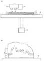
本形態の三次元造形物の製造方法では、インクジェットヘッド14、15から吐出されたインクによって形成されるインク層11をテーブル12の上面に積層して三次元造形物1を製造する。具体的には、以下のように、三次元造形物1を製造する。まず、インク層11を積層して、三次元造形物1と、三次元造形物1を支持するとともに完成後の三次元造形物1と組み合わされて完成後の三次元造形物1の運搬時に三次元造形物1を保護するための支持部材2と、三次元造形物1を支持するために支持部材2とテーブル12との間に配置されるサポート材3と、三次元造形物1を支持するために三次元造形物1と支持部材2との間に配置される分離部材としてのサポート材4とを有する造形物5を形成する(造形物形成工程)。In the production method of the three-dimensional model of the present embodiment, to produce the
三次元造形物1および支持部材2は、造形用のインクであるモデル材によって形成されている。サポート材3、4は、サポート用のインクであるサポート材によって形成されている。すなわち、三次元造形物1および支持部材2と、サポート材3、4とは、異なるインクによって形成されている。インクジェットヘッド14は、三次元造形物1および支持部材2を形成するモデル材を吐出する。インクジェットヘッド15は、サポート材3、4を形成するサポート材を吐出する。したがって、以下では、インクジェットヘッド14を「モデル材吐出部14」とし、インクジェットヘッド15を「サポート材吐出部15」とする。 The three-dimensional model 1 and the
モデル材吐出部14から吐出されるインクは、活性エネルギー線硬化型のインクであり、具体的には、紫外線が照射されると硬化する紫外線硬化型のインクである。サポート材吐出部15から吐出されるインクも、活性エネルギー線硬化型のインクであり、具体的には、紫外線硬化型のインクである。また、サポート材吐出部15から吐出されるインクは、所定の溶媒に溶ける溶解性を有するインクであり、具体的には、溶媒として水を用いることができる水溶性のインクである。すなわち、サポート材3、4は、水溶性のインクによって形成されている。 The ink ejected from the model
モデル材吐出部14およびサポート材吐出部15は、キャリッジ16に搭載されており、テーブル12の上方に配置されている。また、テーブル12の上方には、紫外線を照射する紫外線照射部17が配置されている。紫外線照射部17は、モデル材吐出部14およびサポート材吐出部15と一緒に、または、単独で走査されながら、モデル材吐出部14およびサポート材吐出部15から吐出されたインクに紫外線を照射するものである。ただし、紫外線照射部17は、テーブル12の上面の全体に紫外線を照射するものであっても良い。図1(A)では、走査可能な紫外線照射部17が図示されている。テーブル12には、テーブル12を昇降させる昇降機構18が連結されている。昇降機構18は、モデル材吐出部14およびサポート材吐出部15とテーブル12の上面との間の高さ方向の相対位置を変化させる垂直駆動手段である。また、テーブル12の上面にはアルマイト処理が施されている。 The model
造形物形成工程では、まず、モデル材吐出部14およびサポート材吐出部15の少なくともいずれか一方が1層分のインクを吐出する。具体的には、三次元造形物1の一部分が形成される領域および支持部材2の一部分が形成される領域に、モデル材吐出部14がインクを吐出するとともに、サポート材3、4の一部分が形成される領域に、サポート材吐出部15がインクを吐出する。また、吐出されたインクに紫外線照射部17が紫外線を照射しインクを完全硬化または半硬化させて、1つのインク層11を形成する。1つのインク層11が形成されると、テーブル12がインク層11の厚さに相当する量、下降する。テーブル12が下降すると、同様にして、モデル材吐出部14およびサポート材吐出部15の少なくともいずれか一方が次の1層分のインクを吐出し、吐出されたインクに紫外線照射部17が紫外線を照射してインクを完全硬化または半硬化させて次のインク層11を形成する。 In the molded object forming step, first, at least one of the model
このように、造形物形成工程では、インクの吐出と、吐出されたインクの硬化(完全硬化または半硬化)と、テーブル12の下降とが繰り返されて、図1(A)、(B)に示すように、三次元造形物1と支持部材2とサポート材3、4とを有する造形物5が形成される。すなわち、硬化したインクによって構成される立体的な造形物5がテーブル12上に形成される。本形態では、図1(B)に示すように、三次元造形物1とサポート材4と支持部材2とサポート材3とが上側からこの順番で配置されて重なっている。なお、サポート材3は、テーブル12の上面の微小な凹凸を埋めてテーブル12の上面を平坦にする機能も果たしている。 As described above, in the molded object forming step, the ejection of ink, the curing (complete curing or semi-curing) of the ejected ink, and the lowering of the table 12 are repeated, and the results shown in FIGS. As shown, a three-dimensional model 1, a supporting
造形物形成工程で造形物5が形成されると、その後、サポート材3、4を除去して三次元造形物1と支持部材2とを分離する(分離工程)。サポート材3、4は、上述のように、水溶性のインクによって形成されている。分離工程では、テーブル12から持ち上げた造形物5を水に漬けることで、サポート材3、4を水に溶かして除去することによって三次元造形物1と支持部材2とを分離する。サポート材3、4が除去されると、三次元造形物1および支持部材2が完成する。 After the molded
三次元造形物1および支持部材2が完成すると、その後、三次元造形物1と支持部材2とを組み合わせる(組合せ工程)。具体的には、図1(B)における支持部材2の上面と三次元造形物1の下面とが接触するように、三次元造形物1と支持部材2とを組み合わせて、三次元造形物1を保護する。すなわち、支持部材2は、完成後の三次元造形物2と組み合わされて三次元造形物1を保護する。支持部材2と組み合わされた三次元造形物1は、梱包箱に箱詰めされて運搬される。また、運搬後には、支持部材2と組み合わされた三次元造形物1が箱から取り出されるとともに、三次元造形物1から支持部材2が取り外される。 After the three-dimensional structure 1 and the
なお、サポート材4の厚さは、分離工程において三次元造形物1と支持部材2との間に水が入り込む厚さとなっている。たとえば、サポート材4の厚さは、数ミリメートル程度となっている。また、造形物5では、サポート材4の厚さが一定となっており、支持部材2の上面の形状は、三次元造形物1の下面に応じた形状となっている。すなわち、支持部材2の上面の形状は、三次元造形物1の下面の形状に近い形状となっている。 The thickness of the support material 4 is such that water enters between the three-dimensional structure 1 and the
(本形態の主な効果)
以上説明したように、本形態では、造形物形成工程において、三次元造形物1と、三次元造形物1を保護するための支持部材2と、三次元造形物1と支持部材2との間に配置されるサポート材4とを形成し、その後の分離工程において、サポート材4を除去して三次元造形物1と支持部材2とを分離している。また、本形態では、サポート材4の厚さは一定となっており、支持部材2の上面の形状は、三次元造形物1の下面に応じた形状となっている。さらに、本形態では、分離工程後の組合せ工程において、支持部材2の上面と三次元造形物1の下面とが接触するように三次元造形物1と支持部材2とを組み合わせている。そのため、本形態では、支持部材2と組み合わされて運搬される三次元造形物1を支持部材2によって適切に保護することが可能になる。(Main effects of this embodiment)
As described above, in the present embodiment, the three-dimensional model 1, the
また、本形態では、造形物5において、サポート材3とサポート材4との間に支持部材2が形成されているため、たとえば、造形物5において支持部材2が形成される部分がサポート材となっている場合と比較して、造形物形成工程におけるサポート材用のインクの使用量を低減することが可能になる。また、本形態では、造形物形成工程および分離工程において、三次元造形物1と一緒に支持部材2が形成されているため、運搬時に三次元造形物1を保護するための部材を別途準備する必要がない。したがって、本形態では、造形物5において支持部材2が形成される部分がサポート材となっており、かつ、運搬時に三次元造形物1を保護するための部材が別途準備される場合と比較して、三次元造形物1の製造時および出荷時のトータルコストを低減することが可能になる。 Further, in the present embodiment, since the
本形態では、サポート材3、4は、水溶性のインクによって形成されており、分離工程では、造形物5を水に漬けて、サポート材3、4を水に溶かして除去している。そのため、本形態では、分離工程において、比較的容易に、サポート材3、4を除去することが可能になる。 In the present embodiment, the
(支持部材の変形例1)
上述した形態において、サポート部材除去工程後の支持部材2に複数の穴2aが形成されても良い(図2(A)参照)。図2(A)に示す変形例では、複数の穴2aは、支持部材2の底面から上側に向かって支持部材2を貫通しない範囲に形成されている。また、複数の穴2aは、上下方向から見たときの形状が、たとえば、円形状または四角形状となるように形成されている。この場合、造形物5では、複数の穴2aの中にサポート材3の一部が配置されている。すなわち、この場合には、造形物形成工程において、サポート材3の一部が複数の穴2aの中に配置されるように、サポート材吐出部15からサポート用のインクを吐出させている。一般に、造形用のインクはサポート用のインクよりも高価であるため、図2(A)に示す変形例では、高価な造形用のインクの使用量を低減して、支持部材2を低コストで製造することが可能になる。(Modification 1 of Support Member)
In the above-mentioned form, a plurality of
なお、複数の穴2aが形成される範囲および複数の穴2aの数は、三次元造形物1の適切な保護が可能となる強度を支持部材2が確保できるように設定されている。また、穴2aは、三次元造形物1が有する壊れやすい部分の周囲に、三次元造形物1が支持部材2に接しないように配置されても良い。三次元造形物1が有する壊れやすい部分とは、たとえば、三次元造形物1のうちの細かい造形がなされている部分である。たとえば、三次元造形物1が人形である場合では、人形の指先が壊れやすい部分となる。この壊れやすい部分は、三次元造形物1の造形前であっても、三次元造形物1を造形する際に用いるデータを用いて検出することができる。 The range in which the plurality of
(支持部材の変形例2)
図2(A)に示す変形例では、複数の穴2aは、支持部材2の底面から上側に向かって支持部材2を貫通しない範囲に形成されているが、サポート部材除去工程後の支持部材2に形成される複数の穴2aは、支持部材2の底面から上面まで支持部材2を貫通するように形成されても良い(図2(B)参照)。この場合、造形物5では、複数の穴2aの中にサポート材3、4の一部が配置されている。すなわち、この場合には、造形物形成工程において、サポート材3、4の一部が複数の穴2aの中に配置されるように、サポート材吐出部15からサポート用のインクを吐出させている。図2(B)に示す変形例でも図2(A)に示す変形例と同様に、支持部材2を低コストで製造することが可能になる。また、図2(B)に示す変形例では、分離工程において複数の穴2aを利用して、サポート材4の、水が行き亘りにくい位置に配置された部分にも水を行き亘らせることが可能になる。したがって、この変形例では、分離工程におけるサポート材4の除去がより容易になる。(
In the modification shown in FIG. 2(A), the plurality of
また、支持部材2を貫通するように複数の穴2aが支持部材2に形成される場合には、支持部材2は、立体網目状またはスポンジ状に形成されていても良い。この場合には、支持部材2に、三次元造形物1の緩衝機能を持たせることが可能になるため、運搬時の三次元造形物1の損傷を効果的に防止することが可能になる。なお、三次元造形物1の形状によっては、サポート材4の一部のみが複数の穴2aの中に配置されるように、複数の穴2aが形成されても良い。 When the plurality of
(支持部材の変形例3)
上述した形態において、支持部材2は、図2(C)に示すように、サポート材3側に配置される硬質部2bと、サポート材4側に配置され硬質部2bよりも硬度の低い軟質部2cとから構成されても良い。すなわち、支持部材2は、サポート材4に接する部分に配置されるとともに支持部材2の他の部分(すなわち、硬質部2b)よりも硬度の低い軟質部2cを備えていても良い。すなわち、支持部材2は、分離工程後に三次元造形物1を支持する部分(完成後の三次元造形物1を支持する部分)に、軟質部2cを備えていても良い。この場合には、たとえば、インクジェットヘッドとして、軟質部2cを形成するインクを吐出する軟質材吐出部がキャリッジ16に搭載されており、モデル材吐出部14から吐出されるインクによって硬質部2bが形成され、軟質材吐出部から吐出されるインクによって軟質部2cが形成される。また、この場合には、組合せ工程において三次元造形物1と支持部材2とを組み合わせると、軟質部2cと三次元造形物1が接する。この場合には、サポート材4側に配置される軟質部2cの作用によって、支持部材2に、三次元造形物1の緩衝機能を持たせることが可能になるため、運搬時の三次元造形物1の損傷を効果的に防止することが可能になる。(
In the above-described embodiment, the
(支持部材の変形例4)
上述した形態では、図1(B)における支持部材2の上面と三次元造形物1の下面とが接触するように、三次元造形物1と支持部材2とが組み合わされており、支持部材2は、三次元造形物1を下側から支えている。この他にもたとえば、三次元造形物1を下側から支えるとともに三次元造形物1を上側から覆うように支持部材2が形成されても良いし、三次元造形物1の全体を覆うように支持部材2が形成されても良い。この場合であっても、造形物5では、三次元造形物1と支持部材2との間にサポート材4が配置される。また、三次元造形物1の全体を覆うように支持部材2が形成される場合には、支持部材2は、たとえば、上下方向または水平方向において2分割されている。また、この場合には、支持部材2は、水平方向において3分割以上に分割されていても良い。(Modification 4 of support member)
In the above-described embodiment, the three-dimensional structure 1 and the supporting
また、上述した形態では、図1(B)における支持部材2の上面と三次元造形物1の下面とが接触するように、三次元造形物1と支持部材2とが組み合わされているが、支持部材2の上面と三次元造形物1の下面との間に所定の緩衝材が配置されていても良い。また、支持部材2によって運搬時の三次元造形物1の一部分が保護されるとともに、三次元造形物1が梱包される梱包箱に収容された発泡スチロール等の緩衝部材によって、運搬時の三次元造形物1の残りの部分が保護されても良い。 Further, in the above-described embodiment, the three-dimensional structure 1 and the supporting
(他の実施の形態)
上述した形態において、支持部材2は透明であっても良い。この場合には、三次元造形物1の形状が複雑であっても、組合せ工程において三次元造形物1と支持部材2とを組み合わせるときに、三次元造形物1と支持部材2との位置関係を確認しながら、三次元造形物1と支持部材2とを組み合わせることが可能になる。したがって、三次元造形物1の形状が複雑であっても、三次元造形物1と支持部材2とを組み合わせる際の三次元造形物1の損傷を防止することが可能になる。(Other embodiments)
In the above-mentioned form, the
上述した形態では、三次元造形物1を形成するインクと支持部材2を形成するインクとが同じインクであるが、三次元造形物1を形成するインクと支持部材2を形成するインクとが異なっていても良い。この場合、分離工程において、三次元造形物1と支持部材2とを分離することができるのであれば、三次元造形物1と支持部材2との間にサポート材4が配置されていなくても良い。 In the above-described embodiment, the ink forming the three-dimensional structure 1 and the ink forming the supporting
上述した形態では、サポート材3、4を形成するサポート用のインクは、水溶性のインクであるが、サポート材3、4を形成するサポート用のインクは、水以外の溶媒(たとえば、有機溶剤等)に溶けるインクであっても良い。また、上述した形態では、サポート材3、4を形成するサポート用のインクは、紫外線硬化型のインクであるが、サポート材3、4を形成するサポート用のインクは、サポート材吐出部15から吐出することが可能となっており、かつ、分離工程で除去することが可能になっているのであれば、紫外線硬化型のインク以外のインクであっても良い。 In the above-described embodiment, the support ink forming the
上述した形態では、造形物5において、支持部材2とサポート材4と三次元造形物1とが下側からこの順番で配置されて重なっているが、造形物5において、支持部材2とサポート材4と三次元造形物1とが、水平方向の外側からこの順番で配置されて重なっていても良い。 In the above-described embodiment, in the modeled
1 三次元造形物
2 支持部材
2a 穴
2c 軟質部
4 サポート材(分離部材)
5 造形物
11 インク層
14 モデル材吐出部(インクジェッドヘッド)
15 サポート材吐出部(インクジェッドヘッド)1
5 Modeling
15 Support material discharge part (ink jet head)
Claims (7)
Translated fromJapanese前記インク層を積層して、前記三次元造形物と、前記三次元造形物を支持する支持部材とを有する造形物を形成する造形物形成工程と、
前記造形物形成工程後に、前記三次元造形物と前記支持部材とを分離する分離工程とを備え、
前記支持部材は、前記分離工程の後、前記三次元造形物と組み合わされて、前記三次元造形物を保護することを特徴とする三次元造形物の製造方法。A method of manufacturing a 3D object to produce a laminated three-dimensionally shaped object ink layer formed by ink ejected fromInkjet Head,
A model forming step of forming a model having the three-dimensional model and the supporting member supporting the three-dimensional model by stacking the ink layers.
After the modeling object forming step, a separation step of separating the three-dimensional modeling object and the support member,
The method for manufacturing a three-dimensional structure, wherein the support member is combined with the three-dimensional structure after the separating step to protect the three-dimensional structure.
前記分離部材は、前記支持部材と異なるインクによって形成され、
前記分離工程では、前記分離部材を除去することによって前記三次元造形物と前記支持部材とを分離することを特徴とする請求項1記載の三次元造形物の製造方法。The modeled object includes a separating member arranged between the three-dimensional modeled object and the support member,
The separation member is formed of an ink different from that of the support member,
The method for manufacturing a three-dimensional structure according to claim 1, wherein in the separating step, the three-dimensional structure is separated from the support member by removing the separation member.
前記分離工程では、前記造形物を前記溶媒に漬け、前記分離部材を前記溶媒に溶かして除去することによって前記三次元造形物と前記支持部材とを分離することを特徴とする請求項2記載の三次元造形物の製造方法。The separation member is formed of an ink having a solubility that dissolves in a predetermined solvent,
3. In the separation step, the three-dimensional structure and the support member are separated by immersing the shaped product in the solvent and dissolving the separation member in the solvent to remove it. A method for manufacturing a three-dimensional structure.
前記造形物形成工程では、少なくとも前記分離部材の一部が複数の前記穴の中に配置されるように、前記インクジェットヘッドからインクを吐出させることを特徴とする請求項2または3記載の三次元造形物の製造方法。A plurality of holes are formed in the support member,
Wherein the molded object forming process, as at least a portion of the separating member is disposed within the plurality of holes, tertiary according to claim 2 or 3, wherein the ink is ejected from theInkjet head A method of manufacturing an original shaped article.
Priority Applications (2)
| Application Number | Priority Date | Filing Date | Title |
|---|---|---|---|
| JP2016167709AJP6738116B2 (en) | 2016-08-30 | 2016-08-30 | Method for manufacturing three-dimensional model |
| US15/683,105US20180056580A1 (en) | 2016-08-30 | 2017-08-22 | Manufacturing method for three-dimensional object and three-dimensional structure |
Applications Claiming Priority (1)
| Application Number | Priority Date | Filing Date | Title |
|---|---|---|---|
| JP2016167709AJP6738116B2 (en) | 2016-08-30 | 2016-08-30 | Method for manufacturing three-dimensional model |
Publications (2)
| Publication Number | Publication Date |
|---|---|
| JP2018034350A JP2018034350A (en) | 2018-03-08 |
| JP6738116B2true JP6738116B2 (en) | 2020-08-12 |
Family
ID=61241796
Family Applications (1)
| Application Number | Title | Priority Date | Filing Date |
|---|---|---|---|
| JP2016167709AActiveJP6738116B2 (en) | 2016-08-30 | 2016-08-30 | Method for manufacturing three-dimensional model |
Country Status (2)
| Country | Link |
|---|---|
| US (1) | US20180056580A1 (en) |
| JP (1) | JP6738116B2 (en) |
Families Citing this family (3)
| Publication number | Priority date | Publication date | Assignee | Title |
|---|---|---|---|---|
| CN109435489B (en) | 2018-12-13 | 2020-04-28 | 珠海赛纳打印科技股份有限公司 | Three-dimensional object ink-jet printing method, printing apparatus, and computer-readable storage medium |
| JP7426187B2 (en)* | 2020-03-18 | 2024-02-01 | 株式会社日本触媒 | Photocurable composition for support materials for 3D printers and support materials for 3D printers |
| JP7530228B2 (en)* | 2020-07-22 | 2024-08-07 | 株式会社ミマキエンジニアリング | Manufacturing method for three-dimensional objects |
Family Cites Families (8)
| Publication number | Priority date | Publication date | Assignee | Title |
|---|---|---|---|---|
| US5503785A (en)* | 1994-06-02 | 1996-04-02 | Stratasys, Inc. | Process of support removal for fused deposition modeling |
| DE10007502A1 (en)* | 2000-02-18 | 2001-08-23 | Basell Polypropylen Gmbh | Inner container for household appliances |
| JP2002025837A (en)* | 2000-07-03 | 2002-01-25 | Dainippon Printing Co Ltd | Rotary joint for power transmission |
| US7236166B2 (en)* | 2005-01-18 | 2007-06-26 | Stratasys, Inc. | High-resolution rapid manufacturing |
| JP2008127102A (en)* | 2006-11-24 | 2008-06-05 | Toyo Sangyo Sozo Center | Packing cushioning material |
| US8155775B2 (en)* | 2008-10-02 | 2012-04-10 | Stratasys, Inc. | Support structure packaging |
| GB201216224D0 (en)* | 2012-09-12 | 2012-10-24 | Nobel Biocare Services Ag | An improved virtual splint |
| CN106273438B (en)* | 2015-05-11 | 2019-11-05 | 三纬国际立体列印科技股份有限公司 | Three-dimensional printing forming structure |
- 2016
- 2016-08-30JPJP2016167709Apatent/JP6738116B2/enactiveActive
- 2017
- 2017-08-22USUS15/683,105patent/US20180056580A1/ennot_activeAbandoned
Also Published As
| Publication number | Publication date |
|---|---|
| US20180056580A1 (en) | 2018-03-01 |
| JP2018034350A (en) | 2018-03-08 |
Similar Documents
| Publication | Publication Date | Title |
|---|---|---|
| JP6799431B2 (en) | Manufacturing method of 3D model and model | |
| JP6486189B2 (en) | Three-dimensional printing apparatus and three-dimensional printing method | |
| JP6738116B2 (en) | Method for manufacturing three-dimensional model | |
| JP6294659B2 (en) | Manufacturing method and control device of shaped object | |
| US20170282462A1 (en) | Method for manufacturing three-dimensional shaped object | |
| WO2019163351A1 (en) | Stage mechanism, additive manufacturing device, and additive manufacturing method | |
| JP6643631B2 (en) | Manufacturing method of three-dimensional shaped object | |
| JP2015212042A (en) | Three-dimensional molding device and three-dimensional molding method | |
| JP6493007B2 (en) | Modeling equipment | |
| WO2014041670A1 (en) | Electronic device manufacturing apparatus and method for manufacturing same | |
| JP2020079449A5 (en) | ||
| JP6781978B2 (en) | Three-dimensional object modeling device | |
| KR101896918B1 (en) | Three-dimensional object | |
| JP2016141113A (en) | Lamination molding device and lamination molding program | |
| JP7362433B2 (en) | Additive manufacturing method | |
| KR101738365B1 (en) | Platform apparatus for 3d printer | |
| JP7530228B2 (en) | Manufacturing method for three-dimensional objects | |
| JP2015101011A (en) | Three-dimensional molding device | |
| JP4639133B2 (en) | 3D modeling method | |
| JP2017217889A (en) | Solid object modeling method | |
| JP2019142211A (en) | Additive manufacturing apparatus | |
| JP7066272B2 (en) | Manufacturing method of 3D model | |
| JP2007172473A (en) | Memory card manufacturing method | |
| JP7160700B2 (en) | 3D modeling apparatus, manufacturing method of 3D model | |
| JP7234267B2 (en) | Modeling plate and method of modeling three-dimensional objects using the same |
Legal Events
| Date | Code | Title | Description |
|---|---|---|---|
| A621 | Written request for application examination | Free format text:JAPANESE INTERMEDIATE CODE: A621 Effective date:20181211 | |
| A977 | Report on retrieval | Free format text:JAPANESE INTERMEDIATE CODE: A971007 Effective date:20191016 | |
| A131 | Notification of reasons for refusal | Free format text:JAPANESE INTERMEDIATE CODE: A131 Effective date:20191111 | |
| A521 | Request for written amendment filed | Free format text:JAPANESE INTERMEDIATE CODE: A523 Effective date:20200109 | |
| A131 | Notification of reasons for refusal | Free format text:JAPANESE INTERMEDIATE CODE: A131 Effective date:20200416 | |
| A521 | Request for written amendment filed | Free format text:JAPANESE INTERMEDIATE CODE: A523 Effective date:20200610 | |
| TRDD | Decision of grant or rejection written | ||
| A01 | Written decision to grant a patent or to grant a registration (utility model) | Free format text:JAPANESE INTERMEDIATE CODE: A01 Effective date:20200716 | |
| A61 | First payment of annual fees (during grant procedure) | Free format text:JAPANESE INTERMEDIATE CODE: A61 Effective date:20200716 | |
| R150 | Certificate of patent or registration of utility model | Ref document number:6738116 Country of ref document:JP Free format text:JAPANESE INTERMEDIATE CODE: R150 | |
| R250 | Receipt of annual fees | Free format text:JAPANESE INTERMEDIATE CODE: R250 | |
| R250 | Receipt of annual fees | Free format text:JAPANESE INTERMEDIATE CODE: R250 | |
| R250 | Receipt of annual fees | Free format text:JAPANESE INTERMEDIATE CODE: R250 |