JP6735814B2 - Systems and methods for implant delivery - Google Patents
Systems and methods for implant deliveryDownload PDFInfo
- Publication number
- JP6735814B2 JP6735814B2JP2018506904AJP2018506904AJP6735814B2JP 6735814 B2JP6735814 B2JP 6735814B2JP 2018506904 AJP2018506904 AJP 2018506904AJP 2018506904 AJP2018506904 AJP 2018506904AJP 6735814 B2JP6735814 B2JP 6735814B2
- Authority
- JP
- Japan
- Prior art keywords
- implant
- sheath
- wire
- body member
- delivery
- Prior art date
- Legal status (The legal status is an assumption and is not a legal conclusion. Google has not performed a legal analysis and makes no representation as to the accuracy of the status listed.)
- Active
Links
Images


Classifications
- A—HUMAN NECESSITIES
- A61—MEDICAL OR VETERINARY SCIENCE; HYGIENE
- A61F—FILTERS IMPLANTABLE INTO BLOOD VESSELS; PROSTHESES; DEVICES PROVIDING PATENCY TO, OR PREVENTING COLLAPSING OF, TUBULAR STRUCTURES OF THE BODY, e.g. STENTS; ORTHOPAEDIC, NURSING OR CONTRACEPTIVE DEVICES; FOMENTATION; TREATMENT OR PROTECTION OF EYES OR EARS; BANDAGES, DRESSINGS OR ABSORBENT PADS; FIRST-AID KITS
- A61F2/00—Filters implantable into blood vessels; Prostheses, i.e. artificial substitutes or replacements for parts of the body; Appliances for connecting them with the body; Devices providing patency to, or preventing collapsing of, tubular structures of the body, e.g. stents
- A61F2/95—Instruments specially adapted for placement or removal of stents or stent-grafts
- A61F2/962—Instruments specially adapted for placement or removal of stents or stent-grafts having an outer sleeve
- A61F2/97—Instruments specially adapted for placement or removal of stents or stent-grafts having an outer sleeve the outer sleeve being splittable
- A—HUMAN NECESSITIES
- A61—MEDICAL OR VETERINARY SCIENCE; HYGIENE
- A61F—FILTERS IMPLANTABLE INTO BLOOD VESSELS; PROSTHESES; DEVICES PROVIDING PATENCY TO, OR PREVENTING COLLAPSING OF, TUBULAR STRUCTURES OF THE BODY, e.g. STENTS; ORTHOPAEDIC, NURSING OR CONTRACEPTIVE DEVICES; FOMENTATION; TREATMENT OR PROTECTION OF EYES OR EARS; BANDAGES, DRESSINGS OR ABSORBENT PADS; FIRST-AID KITS
- A61F2/00—Filters implantable into blood vessels; Prostheses, i.e. artificial substitutes or replacements for parts of the body; Appliances for connecting them with the body; Devices providing patency to, or preventing collapsing of, tubular structures of the body, e.g. stents
- A61F2/01—Filters implantable into blood vessels
- A61F2/013—Distal protection devices, i.e. devices placed distally in combination with another endovascular procedure, e.g. angioplasty or stenting
- A—HUMAN NECESSITIES
- A61—MEDICAL OR VETERINARY SCIENCE; HYGIENE
- A61B—DIAGNOSIS; SURGERY; IDENTIFICATION
- A61B17/00—Surgical instruments, devices or methods
- A61B17/12—Surgical instruments, devices or methods for ligaturing or otherwise compressing tubular parts of the body, e.g. blood vessels or umbilical cord
- A61B17/12022—Occluding by internal devices, e.g. balloons or releasable wires
- A61B17/12027—Type of occlusion
- A61B17/1204—Type of occlusion temporary occlusion
- A—HUMAN NECESSITIES
- A61—MEDICAL OR VETERINARY SCIENCE; HYGIENE
- A61B—DIAGNOSIS; SURGERY; IDENTIFICATION
- A61B17/00—Surgical instruments, devices or methods
- A61B17/00234—Surgical instruments, devices or methods for minimally invasive surgery
- A61B2017/00292—Surgical instruments, devices or methods for minimally invasive surgery mounted on or guided by flexible, e.g. catheter-like, means
- A61B2017/00336—Surgical instruments, devices or methods for minimally invasive surgery mounted on or guided by flexible, e.g. catheter-like, means with a protective sleeve, e.g. retractable or slidable
- A—HUMAN NECESSITIES
- A61—MEDICAL OR VETERINARY SCIENCE; HYGIENE
- A61B—DIAGNOSIS; SURGERY; IDENTIFICATION
- A61B17/00—Surgical instruments, devices or methods
- A61B17/12—Surgical instruments, devices or methods for ligaturing or otherwise compressing tubular parts of the body, e.g. blood vessels or umbilical cord
- A61B17/12022—Occluding by internal devices, e.g. balloons or releasable wires
- A61B2017/1205—Introduction devices
- A—HUMAN NECESSITIES
- A61—MEDICAL OR VETERINARY SCIENCE; HYGIENE
- A61B—DIAGNOSIS; SURGERY; IDENTIFICATION
- A61B17/00—Surgical instruments, devices or methods
- A61B17/22—Implements for squeezing-off ulcers or the like on inner organs of the body; Implements for scraping-out cavities of body organs, e.g. bones; for invasive removal or destruction of calculus using mechanical vibrations; for removing obstructions in blood vessels, not otherwise provided for
- A61B2017/22038—Implements for squeezing-off ulcers or the like on inner organs of the body; Implements for scraping-out cavities of body organs, e.g. bones; for invasive removal or destruction of calculus using mechanical vibrations; for removing obstructions in blood vessels, not otherwise provided for with a guide wire
- A61B2017/22042—Details of the tip of the guide wire
- A—HUMAN NECESSITIES
- A61—MEDICAL OR VETERINARY SCIENCE; HYGIENE
- A61B—DIAGNOSIS; SURGERY; IDENTIFICATION
- A61B90/00—Instruments, implements or accessories specially adapted for surgery or diagnosis and not covered by any of the groups A61B1/00 - A61B50/00, e.g. for luxation treatment or for protecting wound edges
- A61B90/03—Automatic limiting or abutting means, e.g. for safety
- A61B2090/037—Automatic limiting or abutting means, e.g. for safety with a frangible part, e.g. by reduced diameter
- A—HUMAN NECESSITIES
- A61—MEDICAL OR VETERINARY SCIENCE; HYGIENE
- A61F—FILTERS IMPLANTABLE INTO BLOOD VESSELS; PROSTHESES; DEVICES PROVIDING PATENCY TO, OR PREVENTING COLLAPSING OF, TUBULAR STRUCTURES OF THE BODY, e.g. STENTS; ORTHOPAEDIC, NURSING OR CONTRACEPTIVE DEVICES; FOMENTATION; TREATMENT OR PROTECTION OF EYES OR EARS; BANDAGES, DRESSINGS OR ABSORBENT PADS; FIRST-AID KITS
- A61F2/00—Filters implantable into blood vessels; Prostheses, i.e. artificial substitutes or replacements for parts of the body; Appliances for connecting them with the body; Devices providing patency to, or preventing collapsing of, tubular structures of the body, e.g. stents
- A61F2/01—Filters implantable into blood vessels
- A61F2/011—Instruments for their placement or removal
- A—HUMAN NECESSITIES
- A61—MEDICAL OR VETERINARY SCIENCE; HYGIENE
- A61F—FILTERS IMPLANTABLE INTO BLOOD VESSELS; PROSTHESES; DEVICES PROVIDING PATENCY TO, OR PREVENTING COLLAPSING OF, TUBULAR STRUCTURES OF THE BODY, e.g. STENTS; ORTHOPAEDIC, NURSING OR CONTRACEPTIVE DEVICES; FOMENTATION; TREATMENT OR PROTECTION OF EYES OR EARS; BANDAGES, DRESSINGS OR ABSORBENT PADS; FIRST-AID KITS
- A61F2/00—Filters implantable into blood vessels; Prostheses, i.e. artificial substitutes or replacements for parts of the body; Appliances for connecting them with the body; Devices providing patency to, or preventing collapsing of, tubular structures of the body, e.g. stents
- A61F2/95—Instruments specially adapted for placement or removal of stents or stent-grafts
- A61F2002/9505—Instruments specially adapted for placement or removal of stents or stent-grafts having retaining means other than an outer sleeve, e.g. male-female connector between stent and instrument
- A—HUMAN NECESSITIES
- A61—MEDICAL OR VETERINARY SCIENCE; HYGIENE
- A61F—FILTERS IMPLANTABLE INTO BLOOD VESSELS; PROSTHESES; DEVICES PROVIDING PATENCY TO, OR PREVENTING COLLAPSING OF, TUBULAR STRUCTURES OF THE BODY, e.g. STENTS; ORTHOPAEDIC, NURSING OR CONTRACEPTIVE DEVICES; FOMENTATION; TREATMENT OR PROTECTION OF EYES OR EARS; BANDAGES, DRESSINGS OR ABSORBENT PADS; FIRST-AID KITS
- A61F2/00—Filters implantable into blood vessels; Prostheses, i.e. artificial substitutes or replacements for parts of the body; Appliances for connecting them with the body; Devices providing patency to, or preventing collapsing of, tubular structures of the body, e.g. stents
- A61F2/95—Instruments specially adapted for placement or removal of stents or stent-grafts
- A61F2/962—Instruments specially adapted for placement or removal of stents or stent-grafts having an outer sleeve
- A61F2/966—Instruments specially adapted for placement or removal of stents or stent-grafts having an outer sleeve with relative longitudinal movement between outer sleeve and prosthesis, e.g. using a push rod
- A61F2002/9665—Instruments specially adapted for placement or removal of stents or stent-grafts having an outer sleeve with relative longitudinal movement between outer sleeve and prosthesis, e.g. using a push rod with additional retaining means
Landscapes
- Health & Medical Sciences (AREA)
- Engineering & Computer Science (AREA)
- Biomedical Technology (AREA)
- Life Sciences & Earth Sciences (AREA)
- General Health & Medical Sciences (AREA)
- Veterinary Medicine (AREA)
- Public Health (AREA)
- Heart & Thoracic Surgery (AREA)
- Vascular Medicine (AREA)
- Animal Behavior & Ethology (AREA)
- Transplantation (AREA)
- Oral & Maxillofacial Surgery (AREA)
- Cardiology (AREA)
- Media Introduction/Drainage Providing Device (AREA)
- Surgical Instruments (AREA)
- Surgery (AREA)
- Reproductive Health (AREA)
- Nuclear Medicine, Radiotherapy & Molecular Imaging (AREA)
- Medical Informatics (AREA)
- Molecular Biology (AREA)
Description
Translated fromJapanese 関連出願
本出願は、2015年8月11日に出願された米国仮出願第62/203,882号、「インプラント配送のためのシステムおよび方法」についての優先権を主張するものであり、その全体は、参照として本明細書に含まれるものである。RELATED APPLICATION This application claims priority to US Provisional Application No. 62/203,882, "Systems and Methods for Implant Delivery," filed August 11, 2015, in its entirety. Are included herein by reference.
インプラントは、多くの理由のため血管系の種々の領域へと配送する必要がある。例えば、塞栓コイルは、空間を遮断するため血管系のターゲット領域に配送することができ、ステントは、部分または血管を支えた開口から迂回して流れるようにターゲット領域に配送することができ、塞栓防止装置(「EPDs」)または血液フィルターは、血管を支えた開口に対するステントまたはバルーニング術の間に取除かれた血栓を捕捉するために、ターゲット領域の下流に配送することができ、血餅レトリーバーは、血栓を捕捉し除去するために、ターゲット領域に配送することができる。 Implants need to be delivered to various regions of the vasculature for many reasons. For example, an embolic coil can be delivered to a target area of the vasculature to block a space, and a stent can be delivered to the target area to bypass a portion or vessel-carrying opening and flow to the target area. Prevention devices (“EPDs”) or blood filters can be delivered downstream of the target area to capture thrombus removed during stenting or ballooning to the vessel-bearing opening, and can be delivered downstream of the clot retriever. Can be delivered to the target area to capture and remove thrombus.
インプラント配送は、他の理由に加え、多くの血管が小サイズであること、血流の高い濁度、曲がりくねった解剖学的特性の故に困難である。インプラントを配送するための典型的な方法は、インプラントをカテーテル/配送装置から押すか、またはカテーテル/配送装置から引き出してインプラントを露出させるかのいずれかを含む。一般には、インプラントの使用にあたり、インプラントが、ターゲット・サイトまたはその付近となるようにして戦略的に装着される。血管系において遭遇する困難な条件の故、配送装置から押された時または配送装置から引き出された時、インプラントは、かなり変位する場合がある。 Implant delivery is difficult due to the small size of many blood vessels, high turbidity of blood flow, and tortuous anatomy, among other reasons. Typical methods for delivering the implant include either pushing the implant from the catheter/delivery device or withdrawing it from the catheter/delivery device to expose the implant. Generally, in using the implant, the implant is strategically placed at or near the target site. Due to the difficult conditions encountered in the vasculature, the implant can be significantly displaced when pushed from or withdrawn from the delivery device.
インプラントを治療サイトに迅速かつ正確に配置することができるインプラント配送システムおよび方法は、したがって望ましい。 Implant delivery systems and methods that allow rapid and accurate placement of implants at treatment sites are therefore desirable.
インプラント配送システムが開示される。 An implant delivery system is disclosed.
1実施形態においては、インプラント配送システムは、インプラントと、インプラントを運搬するインプラント・ワイヤと、シースと、トルク装置とを含む。トルク装置は、切断要素を含み、シースおよびクランプ装置の一部分を収容して、インプラント・ワイヤの一部分を固定する。シースは、トルク装置を通して引き出され、シースを切断するとともにシースをインプラント・ワイヤから分離する。 In one embodiment, an implant delivery system includes an implant, an implant wire that carries the implant, a sheath, and a torque device. The torque device includes a cutting element and houses a portion of the sheath and clamp device to secure a portion of the implant wire. The sheath is pulled through a torque device to cut the sheath and separate it from the implant wire.
1実施形態では、セパレータ・チューブがトルク装置内で切断要素に隣接して配置される。セパレータ・チューブは、切断処理中、別体のシース・ルーメンを通してシースをガイドする。 In one embodiment, a separator tube is located within the torque device adjacent the cutting element. The separator tube guides the sheath through a separate sheath lumen during the cutting process.
1実施形態では、切断要素は、トルク装置内のシース・ルーメンに沿って配置される。 In one embodiment, the cutting element is located along the sheath lumen within the torque device.
1実施形態では、トルク装置は、クランプ要素を含む。クランプ要素は、インプラント・ワイヤ上にコレットを選択的に圧縮するために使用することができる。 In one embodiment, the torque device includes a clamping element. The clamping element can be used to selectively compress the collet onto the implant wire.
1実施形態では、インプラント配送システムは、塞栓防止装置またはフィルタを配送するために使用される。 In one embodiment, the implant delivery system is used to deliver embolic protection devices or filters.
本発明の実施形態の可能な上述のおよび他の構成、特徴および効果は、本発明の実施形態の後述する説明から明らかであり、かつ解明されるところ、添付する図面を参照する。 The foregoing and other possible configurations, features and advantages of the embodiments of the present invention will be apparent and elucidated from the following description of the embodiments of the present invention, with reference to the accompanying drawings.
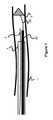
図1は、本発明によるガイド・ワイヤの遠位端、ガイド・ワイヤ、ガイド・カテーテル、配送シース、インプラント配送ワイヤおよびインプラントの実施形態を示す。 FIG. 1 illustrates an embodiment of a distal end of a guide wire, guide wire, guide catheter, delivery sheath, implant delivery wire and implant according to the present invention.
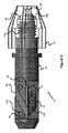
図2〜4は、本発明によるインプラント配送システムにおいて使用されるトルク装置の実施形態を示す。 2-4 illustrate an embodiment of a torque device used in an implant delivery system according to the present invention.
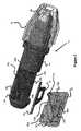
図5は、本発明によるインプラント配送システムにおいて使用されるトルク装置からの切断要素の実施形態を示す。 FIG. 5 shows an embodiment of a cutting element from a torque device used in an implant delivery system according to the invention.
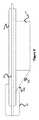
図6は、本発明によるインプラント配送システムにおいて使用されるトルク装置の代替実施形態を示す。 FIG. 6 shows an alternative embodiment of the torque device used in the implant delivery system according to the invention.
本発明の特定の実施形態を添付する図面を参照して説明する。本発明は、しかしながら多くの異なった形態で実施され、本明細書で述べる実施形態に限定して解釈されるものではなく、むしろこれらの実施形態は、本開示が全体的で、かつ完結しており、当業者に対して本発明の範囲を完全に提供するべく提供されるものである。添付する図面において示される実施形態の詳細な説明において使用される用語は、本発明を限定することを意図するものではない。図面においては、同様の符号は、同様の要素を参照する。 Specific embodiments of the present invention will be described with reference to the accompanying drawings. The present invention, however, is embodied in many different forms and should not be construed as limited to the embodiments set forth herein, but rather to these embodiments as a whole and complete disclosure of the present disclosure. Therefore, it is provided to provide those skilled in the art with the full scope of the present invention. The terms used in the detailed description of the embodiments shown in the accompanying drawings are not intended to limit the invention. In the drawings, like numbers refer to like elements.
インプラントまたはEPDs、フィルタ、コイル、プラグ、オクルーダー、ステント、血餅レトリーバー、その他のインプラントといった血管系装置の配送は、医療的処置がしばしば頭部内の血管など微細な血管内において行われることから、典型的には相対的に小さなカテーテルまたは配送装置を介して配送される。この小さなサイズにもかかわらず、配送システムは、両方ともが高い圧迫強度を有して装置を治療サイトに配置しなければならず、かつ曲がりくねった可能性のある血管系を誘導しなければならない。 Delivery of vascular devices such as implants or EPDs, filters, coils, plugs, occluders, stents, clot retrievers, and other implants, as medical procedures are often performed in small blood vessels, such as those in the head, It is typically delivered via a relatively small catheter or delivery device. Despite this small size, the delivery system must both place the device at the treatment site with high compression strength and guide the potentially tortuous vasculature.
従来の配置方法は、典型的には、図1に示すように、血管1の治療部分に近づくため、ガイド・カテーテル3を使用することを含む。ガイド・ワイヤ2は、まずその遠位端が治療部分または近くに位置するまで患者の血管1を通して前進される。次いで、ガイド・カテーテル3が、その遠位端がまた、血管1の治療部分または近くに配置されるまで、ガイド・ワイヤ2越しに進められる。インプラント5は、その後、シース30の遠位端が治療サイトに配置されるまで、ガイド・カテーテル3を通して配送シース30、カテーテル又は他の配送装置内で輸送される。最後に、インプラント5は、装着された配送ワイヤ28を進めることによってシース30の外に押されるかまたはシース30が引っ張られてインプラント5を露出させる。 Conventional placement methods typically include using a guide catheter 3 to access the treated portion of the blood vessel 1, as shown in FIG. The guide wire 2 is first advanced through the patient's blood vessel 1 until its distal end is located at or near the treatment site. The guide catheter 3 is then advanced over the guide wire 2 until its distal end is also located at or near the treated portion of the blood vessel 1. The implant 5 is then transported within the
血流の曲がりくねり、より小さな血管サイズ(他の要因の中でも)の故に治療サイトにおいて利用することが可能性として制限される空間の故、シース30が引っ張られるとインプラント5が移動するという傾向の故に、配送処理は、難しさを残している。インプラント5が配送の間に大きく変位すると、外科医は、再度インプラント5を治療サイトまで誘導しなければならず、これは侵襲処置の間の貴重な時間を要求する可能性がある。 Due to the tortuousness of blood flow and the potentially limited space available at the treatment site due to the smaller vessel size (among other factors), the tendency of implant 5 to move when
この観点において、本発明の実施形態は、医師がインプラント5およびその配送ワイヤ28の両方を、ターゲット・サイトに相対して固定するとともに、また近位にある切断装置を介して外側のデリバリー・シース30を引き抜き除去すること(一部または全部のいずれかの除去)を可能とする配送システムを意図するものである。したがって、外側の配送シース30は、配送システムの近位部分から処置の間に配送ワイヤ28をアンロックする必要なく配送ワイヤ28から迅速に引き抜かれ、分離することができる。 In this regard, embodiments of the present invention provide for the physician to fix both the implant 5 and its
後述する実施形態は、シースが引っ張られてインプラント5が露出され装着されるようにしながらシース30を切断するシース切断システムを使用する。1実施形態では、インプラント配送システムは、装着された配送ワイヤを備える塞栓防止装置(EPD)を配送するために使用される。塞栓防止装置は、血管フィルタの形式とされている。これらは、しばしば治療サイトから離れて配置される。1実施例においては、ステントまたはバルーンは、石灰化した部分を拡張して、血栓が形成された領域において血液を流すことを可能とするために使用される。ステントまたはバルーンを配送する前に、塞栓防止装置又はフィルターがこのターゲット部分の下流に配置され、ステントまたはバルーンによって除去されたいかなる血栓でもEPDにより捕捉させて、血栓が遠い位置に集積されて爾後に問題を生じさせることがないようにされる。EPDまたはフィルタは、時間的な後に除去される。用語インプラント・ワイヤまたは配送ワイヤが使用されているが、これらの用語は、ワイヤ、ハイポチューブ、ロッド、または他の機構を含み、さらにはインプラントが連結され、装着される要素を広く意図して参照する。 The embodiments described below use a sheath cutting system that cuts the
図2−4は、インプラント配送システムの近位部分に配置されるトルク装置10の種々の構成を示す。トルク装置10は、インプラント配送システムがインプラントを血管系1内の適切な治療サイトへと誘導するため、手順の間、好ましくはガイド・カテーテル3の近くに配置される。図面を参照すると、患者に対する手順に関連して左側が遠位であり、右側が近位である。したがって、トルク装置10の左側がガイド・カテーテル3の近位端の次または付近に配置され、インプラント5は、インプラント・ワイヤ28の遠位端に連結され(図1参照)、かつインプラントは、インプラントがすでに配送されている場合、ガイド・カテーテル3または血管1内のいずれかに配置されている。 2-4 show various configurations of the
上述したように、トルク装置10は、トルク装置10に対する配送ワイヤ28の位置をロックするためのロック機構の他、シース30をスリットし、配送ワイヤ28からシース30を分離するための切断機構を含む。まず、切断機構について言えばは、その目的は、シース30が引き抜かれるにつれてシース30を切断し、治療サイトにおいてインプラントを露出させることである(図1および4を参照)。トルク装置10は、切断要素12を含み、切断要素12は、好ましくはシースの一面または側部のみを切断して、シース30の長さにわたって長手方向に走るスリットを生成するように構成される。1実施例では、切断要素12は、金属または硬化ポリマから構成される鋭利なブレードである。 As described above, the
トルク装置10のボディ部材11の遠位部分は、シース30およびインプラント・ワイヤ28が横断する共通通路32を含んでいる。共通通路32は、より近い位置でシース・ルーメン16およびインプラントワイヤ・ルーメン34へと分離する(図2に最も良く見られる)。しかしながら、共通通路及びインプラントワイヤ・ルーメン34は、互いに位置合わせされ、代替的に単一の延びた通路として想定することができる。切断要素12は、この分岐位置の近くに配置されており、鋭利なエッジ12aが遠位方向に向けられ、かつシース30の底部を通して切断するにちょうど十分なように共通通路32内に突出している。切断要素12は、概ねインプラントワイヤ・ルーメン34に位置合わせおよび配置されたセパレータ通路14を備えており、インプラント・ワイヤ28を通過させる。シース・ルーメン16は、切断要素12およびインプラントワイヤ・ルーメン34から離れて位置合わせされており(例えば、切断要素12の反対側または離間する方向に)、スリットされたシース30を、インプラント・ワイヤ28に対して斜めまたは離間する方向に向かわせている。インプラント・ワイヤ28は、シース30をその切断されたスリットを通して脱出し、トルク装置10におけるその位置を保持している。 The distal portion of
1実施形態では、シース30は、切断処理を容易にするために、切断要素12の鋭利な端部12aに位置合わせされた弱領域または予形成したスリットを含むことができる。例えば、この弱められた、または予形成したスリットは、シース30の近位端または端部に配置することができる。他の実施形態では、シース30は、弱領域または予形成されたスリットを有せず、鋭利な端部12は、シースをスリットするに充分である。 In one embodiment, the
トルク装置10の遠位端は、選択的にインプラント・ワイヤ28をその場でクランプするクランプ機構を含む。より具体的には、コレット20が、インプラントワイヤ・ルーメン34を位置合わせする通路を有するトルク装置10の近位端に配置される。装置10のボディ11は、ボディ11の近位端に、コレット20を取り囲むようにおよび/または隣接して配置されるねじ部分11aを含む。対となるねじは、ねじ要素18の内側に配置されていて、ねじ要素18がボディにねじ込まれるようにされている。ねじ要素18の端部の近い側の通路18bは、インプラント・ワイヤ28を必要に応じて通過させている。 The distal end of the
ねじ要素18がボディ11のねじ11a上に遠位的にねじ込まれるにつれ、その内側面18aは、コレット20の傾斜した外側面を圧迫してコレット20がその内側通路のサイズを圧縮または減少させる。インプラント・ワイヤ28は、コレット20を通して位置決めされている場合、コレット20は、ワイヤ20の周りを圧迫またはクランプして、トルク装置10に対しその長手方向および回転位置を固定する。ボディ11に対して近づくように反対側にねじ要素18を回転すると、ねじ要素18の内側面18aがコレット20から離れるように移動して、インプラント・ワイヤ28の圧迫またはクランプを開放し、ボディ11に対するワイヤ28の移動を可能とする。インプラント・ワイヤ28が固定できるので、その遠位端でインプラント・ワイヤ28に連結されたインプラント5は、同様に固定される。したがって、医師は、コレット20を固定して、患者内でインプラント5の位置を固定し、シース30を引き出してインプラント5を露出させ、インプラント5が装置の遠位端に滞留し、相対的に固定される。血流の高い濁度がインプラントをある程度わずかに移動させる可能性があるが、コレット20をロックすることで、そうでなければ発生するいかなる実質的な移動でも概ね低減する。 As the threaded
コレット20は、多くの異なる設計から選択することができる。例えば、コレット20は、一つまたはそれ以上の切り口が、その長さに沿って刻まれて、ねじ要素18がそれに対して遠近移動するするにつれ、伸長し、収縮するばね鋼で構成することができる。コレット20の他の実施形態は、柔軟性のある連結媒体(例えば、合成または天然ゴム)により円形位置(スター形状のポイント様、または実際上、顎付きチャックの顎)で保持されたいくつかのテーパ付き金属ブロックを有する。
従来の配送システムの1つの不便益点は、インプラントが押される際またはシースが引き抜かれる際に、シースとインプラントとの間の機械的な内部遊びのため、インプラントの配送の間、周りに移動することである。本実施形態のユーザは、クランピング機能(ねじ部材およびコレット)によりインプラントをその場に固定できるので、インプラントはより良好にその位置を保持するため、インプラント配送は、より円滑に進む。 One disadvantage of conventional delivery systems is that they move around during delivery of the implant as the implant is pushed or the sheath is withdrawn due to mechanical internal play between the sheath and the implant. That is. The implant delivery can proceed more smoothly because the user of the present embodiment can fix the implant in place by the clamping function (screw member and collet), so that the implant better holds its position.
上述したように、トルク装置10は、セパレータ・チューブ14を含んでいて、シースおよびインプラント・ワイヤが互いに通路16、43にそれぞれ分離することを確実にさせている。1実施例では、セパレータ・チューブ14は、ポリマー・チューブであり、共通通路32の部分内で切断要素12のちょうど上側に配置されて、インプラント・ワイヤ通路34内に延びている(図3−5を参照)。セパレータ・チューブ14は、また他の実施例では金属とすることができる。図5に最もよく示されるように、シース30は、セパレータ・チューブの近位端の周り近くに引き出されており、インプラント・ワイヤ28は、セパレータ・チューブ14およびインプラントワイヤ・ルーメン34の内部を通っている。切断要素12の鋭利なエッジ12aは、セパレータ・チューブ14の底部に延びているかまたは近接していて、シース30が、切断要素12を超えて通過する際に、シース30の底部部分30aを切断することを可能としている。 As mentioned above, the
1実施形態では、ボディ部材11は、トルク装置10の通路16、32、34を完全に形成する。他の実施形態では、図2および図4に示すようにいくつかの別々の部品がトルク装置10を構成する。図2の通路16、32、34は、図3の分解図により良く示されており、対応片22がボディ部材11に結合して適合し、トルク装置10に一体となった通路を画成する。 In one embodiment, the
これとは別に、通路16、32、34は、対応片22の溝部分16a、32a、34a、およびボディ部材11の溝部分16b、32b、34bから構成される。一度結合されると、溝は、それぞれ整列して上述した通路16、32、34を生成する。好ましくは、溝部分は、ボディ部材11および対応片22の両方で等しい深さを有する。これとは別に、溝は、通路の不均等な部分を形成するか、または一方の部品のうちの1つだけ(例えばボディ部材11)が溝を有していても良く、他の部品(例えば、対応片)が、押し付けて通路16、32、34を完成させるフラットな溝のない部分(すなわち、これらの通路の径は、完全な円とされなくとも良い)を有していても良い。 Apart from this, the
図3に最もよく示されるように、対応片22およびボディ部材11は、それぞれ互いに位置合わせできるアパーチャ26a、26bを有する。一度位置合わせされると、ねじまたはその他の機械的アタッチメント機構が両方の開口26a、26bを通して配置されて、対応片22をボディ部材11に結合する。これとは別に、対応片22は、アパーチャの代わりにボディ11のアパーチャ26bに嵌入するポストを含むことができ、また、接着剤または他の既知の結合材料および技術を使用することができる。 As best shown in FIG. 3, the
トルク装置10を多数の対応する要素で製造することの1つの利点は、分離した別々の切断要素12をこれらの要素の間に配置またはマウントすることができることにある。図3に示すように、切断要素12(および任意にセパレータ・チューブ14)は、対応片22およびトルク装置10のボディ部材11の窪み33a、33bによって形成されるキャビティ内に配置することができる。 One advantage of manufacturing the
図6は、他の実施形態のトルク装置40を示しており、これは上述したトルク装置10と概ね類似する。しかしながら、図2−4のトルク装置10は、共通通路32がシース通路16と、インプラント・ワイヤ通路34とに分かれる前に、通路32の底部近くに切断要素12を位置決めし、図6のトルク装置40は、シース通路16の前/遠位部分近くにシース通路16と一体にマウントされた切断要素12を位置決めする。切断要素12の鋭利なエッジ12aは、通過するにつれてシース30の部分を切断またはスプリットするトルク装置10について示したと類似する角度で、遠くに配置されている。セパレータ・チューブ14は、共通通路32がすでにシース通路16とインプラント・ワイヤ通路34に分岐している故に、必要ではない。 FIG. 6 shows another embodiment of a
手術において、トルク装置10は、患者の身体の外部でガイド・カテーテル3の近くに配置される。ガイド・カテーテルは、ガイド・ワイヤ2越しに患者の血管系を通してターゲット治療サイトの近傍の適切な位置まで誘導される。ガイド・ワイヤ2は、その後引き抜かれ、ガイド・カテーテル3のルーメンが配送シース30を配送するために使用される(図1は、説明の便宜のためにのみ、ガイド・カテーテル3内のシース30およびガイド・ワイヤ2の両方を同時に示すことに留意されたい。)。配送シース30は、ガイド・カテーテル3を通して移動して、治療サイトまたはその近くに配置される。インプラント5は、配送シース30の遠位端近くで予め装着されているか、または配送シース30を通して移動しているかのいずれかである。 In surgery, the
インプラント5は、インプラント配送ワイヤ28に装着されているか、連結されている。一度配送シース30が配置されると、配送シース30は、トルク装置10を通して引き抜かれる。配送シース30は、共通通路32を通して近くを通過し、切断要素12によってスリットされ、シース通路16を通してインプラント配送ワイヤ28から軸に沿って斜めに離れて移動する。配送シースを引き抜く前に、インプラント配送ワイヤ28は、ねじ要素18を回転させることによって、コレット20がインプラント配送ワイヤ28を圧迫し、配送シース30が引き抜かれる際にインプラント5が患者内の固定された相対位置に任意的に保持されるように固定することができる。 The implant 5 is attached to or connected to the
装着後、インプラント配送ワイヤ28は、追加的な装置を移動させるためのガイド・ワイヤとして機能する。インプラント5がEPDまたはフィルタである1実施例において、インプラント5は、ターゲット治療サイトの遠くに配置される。一度、EPD/フィルタが配置されシース30が引き抜かれてスリットされると、インプラント配送ワイヤ28は、ステントまたはバルーンを治療サイトに移動させて石灰化部分を治療するためのガイド・ワイヤとして使用される。ステントまたはバルーンは、依然として配置されたままのガイド・カテーテル3を導管として使用することができ、または他の配送カテーテルがインプラント配送ワイヤ28越しに移動される。ステントまたはバルーンは、EPD/フィルターの近くに配置される。ステントまたはバルーンは、血管1を支えて開くために膨張され、手術の後、時間経過後、EPDまたはフィルターは、取り出しカテーテルを使用して、取り出しカテーテルに対してEPD/フィルタをピニングすることによって引き抜かれる。 After installation, the
他の実施形態は、迅速交換ガイドワイヤ・システムを使用する。1実施例では、ガイド・カテーテル3は、ガイド・ワイヤ2の取り出しおよび挿入に適合した側部ポートを有する。したがって、ガイド・ワイヤ2は、ガイド・カテーテル3の全長を通して移動される必要はない。ガイド・ワイヤ2は、ガイド・カテーテル3の側部ポートを通して配置され、ガイド・カテーテル3は、ガイド・ワイヤ2越しに押し込まれる。一度ガイド・カテーテル3が配置されると、ガイド・ワイヤ2は、側部ポートを通して引き抜かれ、配送シース(およびその中に配置されたインプラント5)30がガイド・カテーテル3を通して治療サイトへと押し込まれる。 Other embodiments use a rapid exchange guidewire system. In one embodiment, the guide catheter 3 has side ports adapted for removal and insertion of the guide wire 2. Therefore, the guide wire 2 does not have to be moved through the entire length of the guide catheter 3. The guide wire 2 is placed through the side port of the guide catheter 3 and the guide catheter 3 is pushed over the guide wire 2. Once the guide catheter 3 is in place, the guide wire 2 is withdrawn through the side port and the delivery sheath (and implant 5 placed therein) 30 is pushed through the guide catheter 3 to the treatment site. ..
他の実施形態は、インプラント5それ自体がガイド・ワイヤ2に適合するポートを有する迅速交換ガイドワイヤ・システムを使用する。ガイド・ワイヤ2は、インプラント5を通して予め装着され、インプラント5は、配送シース30内に配置され、配送シース30は、ガイド・カテーテル3内に位置決めされる。インプラント5および配送シース30は、治療サイトまでガイド・ワイヤ2越しに押し込まれる。一度治療サイトに配置されると、ガイド・ワイヤ2は、ガイド・ワイヤ2を引き戻すことによって引き抜かれる。ガイド・ワイヤ2は、インプラント5およびガイド・カテーテル3の長さを通して、またはガイド・カテーテル3の側部ポートを通してのいずれかを通して引っ張られる。インプラント配送ワイヤ28は、その後、上述した様な追加のインプラントのための導管として使用される。 Another embodiment uses a rapid exchange guidewire system where the implant 5 itself has a port that fits the guidewire 2. The guide wire 2 is preloaded through the implant 5, the implant 5 is placed in the
インプラント配送システムは、EPDs、フィルター、コイル、プラグ、オクルーダー、ステント、血餅レトリーバー、または他のインプラントといった多種のインプラントを配送するために使用することができる。上述した使用方法の実施形態は、いかにして、ある者がEPDのインプラント・ワイヤを、さらなるインプラントを配送するための機構として使用することができるかを詳述したが、この同一の原理は、EPD’s以外のインプラントに対しても適用することができる。 The implant delivery system can be used to deliver a wide variety of implants such as EPDs, filters, coils, plugs, occluders, stents, clot retrievers, or other implants. The above-described embodiments of the method of use have detailed how one can use an EPD implant wire as a mechanism to deliver additional implants, but this same principle is: It can be applied to implants other than EPD's.
インプラント5を配送シース30を通して配送すること、トルク装置10機構を通して配送シース30を引っ張ってシース30を切断し、インプラント5を露出させることは、また、多種のインプラントについても使用することができる。トルク装置10のコレット20を圧迫してインプラントを固定する能力および配送シース30を切断してインプラントを露出させることは、本技術の特徴である。 Delivering the implant 5 through the
本方法の変形例および本発明の実施形態はさらに、切断要素12を使用することなく、ねじ18およびコレット20の構成を、インプラント28を固定し、その後配送シース30を引っ張るために使用することを含む。このような実施形態においては、インプラント5は、固定された位置にあり、配送シース30は、切断するのではなくトルク装置10を通して単純に引っ張られる。したがって、切断要素12を除き、図1−5のトルク装置10に類似する装置が使用できる。配送シース30は、切断されるのではなく、その代わりにシース通路16を通して引っ張られる。この実施形態は、コイル、ステント、EPD’s、フィルタ、プラグ、オクルーダー、血餅レトリーバーまたは他のインプラントに使用することができる。これらの装置の1つまたはそれ以上は、インプラント配送ワイヤ28に固定または連結され、配送シース30を通じて配送される。配送シース30は、その後引き抜かれてインプラントが露出される。ユーザは、任意に配送ワイヤ28越しにコレット20の圧迫を通じてインプラントを固定し、配送手順の間のインプラントの運動を最小化することができる。 The method variants and embodiments of the present invention further contemplate the use of the
本明細書に記載したいかなる基準、図面、材料でもその性質上例示を意味するにすぎないものであり、文言的に開示されたものを特定的に限定することを意味するものではない。 Any criteria, drawings, or materials set forth herein are meant to be exemplary in nature and not meant to limit the language specifically disclosed.
本発明を特定の実施形態及び用途を以て説明したが、当業者は、本教示に照らし、請求項に記載した発明の精神はら乖離することなく、または範囲を超えて追加の実施形態、修正を生成することができる。したがって、本明細書の図面および記述は、発明の理解を容易にする実施例として提供されたものであって、その範囲の制限するものとして理解されるべきではない。
While the present invention has been described in terms of particular embodiments and uses, those of ordinary skill in the art will appreciate that additional embodiments and modifications will be apparent to those skilled in the art in light of the present teachings and without departing from the spirit of the claimed invention. can do. Therefore, the drawings and the description of the present specification are provided as examples for facilitating the understanding of the invention and should not be understood as limiting the scope thereof.
Claims (4)
Translated fromJapanese延びたインプラント・ワイヤ(28)上に配置されたスリット・シース(30)を取り除くように構成されたトルク装置(10)であって、該延びたインプラント・ワイヤは、患者の治療のために構成されるインプラント(5)に連結された遠位端を有する、トルク装置(10)を備え、該トルク装置(10)は、
溝部分(16b、32b、34b)を有するボディ部材(11)と;
前記ボディ部材(11)に取り外し可能に結合して適合する溝部分(16a、32a、34a)を有する対応片(22)と;
前記ボディ部材(11)を通して延びている第1の通路(32)であって、互いに整合する前記ボディ部材(11)の溝領域(32b)と前記対応片(22)の中の溝領域(32a)とを含み、前記ボディ部材(11)を通して続く第1の通路(32)と;
前記第1の通路内に取り外し可能に配置され、前記延びたインプラント・ワイヤの通過を可能にするセパレータ部材であって、セパレータ・チューブ(14)と、該チューブ(14)に固定され、該チューブ(14)の遠位端の近位に配置された切断要素(12)とを含むセパレータ部材と;
前記切断要素の近位で前記第1の通路に接続する第2の通路(16)であって、前記第1の通路から離れて延びており、互いに嵌合する前記ボディ部材(11)の溝領域(16b)と前記対応片(22)の中の溝領域(16a)とを含む第2の通路(16)と;
前記延びたインプラント・ワイヤを選択的に押圧するクランプ機構(20)と;によって特徴付けられ、
前記切断要素は、前記ボディ部材(11)および前記対応片(22)との間で前記第1の通路に位置決めされ、前記第1の通路を通して通過する前記シース(30)をスリットし、
前記トルク装置は、前記患者の体内において前記インプラントを決まった場所に残しながらスリットされた前記シースを前記第2の通路内に向かわせ、
前記クランプ機構(20)は、前記ボディ部材(11)および前記対応片(22)に対する前記延びたインプラント・ワイヤ(28)の位置を保持するインプラント配送システム。An implant delivery system,
A torque device (10) configured to remove a slit sheath (30) disposed on an extended implant wire (28), the extended implant wire configured for treatment of a patient. A torque device (10)having a distal end connected to an implant (5), the torque device (10) comprising:
A body member (11) having groove portions (16b, 32b, 34b);
A counterpiece (22) having groove portions (16a, 32a, 34a) for removably coupling and fitting to said body member (11);
A first passageway (32) extending through the body member (11), the groove region (32b) of the body member (11) and the groove region (32a of the corresponding piece (22) aligned with each other. ) And a first passageway (32) continuing through said body member (11);
The first is removably disposed within the passage, a separator member to permit passage ofthe implant wire extending, the separator tube (14) is fixed to the tube (14), the tube A separator member comprising a cutting element (12) disposed proximal to the distal end of (14);
A second passageway (16) connecting to the first passageway proximal to the cutting element, the groove of the body member (11) extending away from the first passageway and fitting together. A second passageway (16) including a region (16b) and a groove region (16a) in the counterpiece (22);
A clamping mechanism (20) for selectively pressing the elongated implant wire;
The cutting element, wherein is positioned in the first passage between the body member (11) and the corresponding piece (22), and slitthe sheath (30) passing through said first passage,
The torque device directs the slit sheath into the second passage while leaving the implant in placewithin the patient's body;
An implant delivery systemwherein the clamp mechanism (20) holds the position of the extended implant wire (28) relative to the body member (11) and the counterpiece (22) .
Applications Claiming Priority (3)
| Application Number | Priority Date | Filing Date | Title |
|---|---|---|---|
| US201562203882P | 2015-08-11 | 2015-08-11 | |
| US62/203,882 | 2015-08-11 | ||
| PCT/US2016/046620WO2017027740A1 (en) | 2015-08-11 | 2016-08-11 | System and method for implant delivery |
Publications (3)
| Publication Number | Publication Date |
|---|---|
| JP2018522681A JP2018522681A (en) | 2018-08-16 |
| JP2018522681A5 JP2018522681A5 (en) | 2019-10-24 |
| JP6735814B2true JP6735814B2 (en) | 2020-08-05 |
Family
ID=57983737
Family Applications (1)
| Application Number | Title | Priority Date | Filing Date |
|---|---|---|---|
| JP2018506904AActiveJP6735814B2 (en) | 2015-08-11 | 2016-08-11 | Systems and methods for implant delivery |
Country Status (5)
| Country | Link |
|---|---|
| US (4) | US10492938B2 (en) |
| EP (1) | EP3334354B1 (en) |
| JP (1) | JP6735814B2 (en) |
| CN (1) | CN107847243B (en) |
| WO (1) | WO2017027740A1 (en) |
Families Citing this family (190)
| Publication number | Priority date | Publication date | Assignee | Title |
|---|---|---|---|---|
| EP1951129B1 (en) | 2005-10-19 | 2012-11-21 | Pulsar Vascular, Inc. | Methods and systems for endovascularly clipping and repairing lumen and tissue defects |
| US9402707B2 (en) | 2008-07-22 | 2016-08-02 | Neuravi Limited | Clot capture systems and associated methods |
| WO2010028314A1 (en) | 2008-09-05 | 2010-03-11 | Pulsar Vascular, Inc. | Systems and methods for supporting or occluding a physiological opening or cavity |
| US8579964B2 (en) | 2010-05-05 | 2013-11-12 | Neovasc Inc. | Transcatheter mitral valve prosthesis |
| ES2683943T3 (en) | 2010-10-22 | 2018-09-28 | Neuravi Limited | Clot capture and removal system |
| US11259824B2 (en) | 2011-03-09 | 2022-03-01 | Neuravi Limited | Clot retrieval device for removing occlusive clot from a blood vessel |
| EP4566553A3 (en) | 2011-03-09 | 2025-08-06 | Neuravi Limited | A clot retrieval device for removing occlusive clot from a blood vessel |
| US12076037B2 (en) | 2011-03-09 | 2024-09-03 | Neuravi Limited | Systems and methods to restore perfusion to a vessel |
| US9308087B2 (en) | 2011-04-28 | 2016-04-12 | Neovasc Tiara Inc. | Sequentially deployed transcatheter mitral valve prosthesis |
| US9554897B2 (en) | 2011-04-28 | 2017-01-31 | Neovasc Tiara Inc. | Methods and apparatus for engaging a valve prosthesis with tissue |
| CN103582460B (en) | 2011-06-03 | 2019-03-19 | 帕尔萨维斯库勒公司 | Aneurysm devices and related systems and methods with additional anchoring mechanism |
| US9119625B2 (en) | 2011-10-05 | 2015-09-01 | Pulsar Vascular, Inc. | Devices, systems and methods for enclosing an anatomical opening |
| US9345573B2 (en) | 2012-05-30 | 2016-05-24 | Neovasc Tiara Inc. | Methods and apparatus for loading a prosthesis onto a delivery system |
| US10561509B2 (en) | 2013-03-13 | 2020-02-18 | DePuy Synthes Products, Inc. | Braided stent with expansion ring and method of delivery |
| US10603157B2 (en) | 2013-03-13 | 2020-03-31 | DePuy Synthes Products, Inc. | Braid implant delivery and retraction device with distal engagement |
| US9433429B2 (en) | 2013-03-14 | 2016-09-06 | Neuravi Limited | Clot retrieval devices |
| WO2014140092A2 (en) | 2013-03-14 | 2014-09-18 | Neuravi Limited | Devices and methods for removal of acute blockages from blood vessels |
| ES2708786T3 (en) | 2013-03-14 | 2019-04-11 | Neuravi Ltd | Clot recovery device to remove occlusive clots from a blood vessel |
| US9572665B2 (en) | 2013-04-04 | 2017-02-21 | Neovasc Tiara Inc. | Methods and apparatus for delivering a prosthetic valve to a beating heart |
| US9265512B2 (en) | 2013-12-23 | 2016-02-23 | Silk Road Medical, Inc. | Transcarotid neurovascular catheter |
| US10285720B2 (en) | 2014-03-11 | 2019-05-14 | Neuravi Limited | Clot retrieval system for removing occlusive clot from a blood vessel |
| US11154302B2 (en) | 2014-03-31 | 2021-10-26 | DePuy Synthes Products, Inc. | Aneurysm occlusion device |
| US11076860B2 (en) | 2014-03-31 | 2021-08-03 | DePuy Synthes Products, Inc. | Aneurysm occlusion device |
| JP6595513B2 (en) | 2014-06-13 | 2019-10-23 | ニューラヴィ・リミテッド | Device for removal of acute occlusions from blood vessels |
| US10265086B2 (en) | 2014-06-30 | 2019-04-23 | Neuravi Limited | System for removing a clot from a blood vessel |
| US9918718B2 (en) | 2014-08-08 | 2018-03-20 | DePuy Synthes Products, Inc. | Embolic coil delivery system with retractable mechanical release mechanism |
| US10206796B2 (en) | 2014-08-27 | 2019-02-19 | DePuy Synthes Products, Inc. | Multi-strand implant with enhanced radiopacity |
| US9782178B2 (en) | 2014-09-19 | 2017-10-10 | DePuy Synthes Products, Inc. | Vasculature occlusion device detachment system with tapered corewire and heater activated fiber detachment |
| EP3682821B1 (en) | 2014-11-26 | 2022-05-11 | Neuravi Limited | A clot retrieval device for removing an occlusive clot from a blood vessel |
| US10617435B2 (en) | 2014-11-26 | 2020-04-14 | Neuravi Limited | Clot retrieval device for removing clot from a blood vessel |
| US11253278B2 (en) | 2014-11-26 | 2022-02-22 | Neuravi Limited | Clot retrieval system for removing occlusive clot from a blood vessel |
| CN119949953A (en) | 2015-02-04 | 2025-05-09 | 92号医疗公司 | Intravascular access system, dilator and system including dilator |
| US10426497B2 (en) | 2015-07-24 | 2019-10-01 | Route 92 Medical, Inc. | Anchoring delivery system and methods |
| US11065019B1 (en) | 2015-02-04 | 2021-07-20 | Route 92 Medical, Inc. | Aspiration catheter systems and methods of use |
| US10492938B2 (en) | 2015-08-11 | 2019-12-03 | Terumo Corporation | System and method for implant delivery |
| CA3007660A1 (en) | 2015-12-15 | 2017-06-22 | Neovasc Tiara Inc. | Transseptal delivery system |
| US10433952B2 (en) | 2016-01-29 | 2019-10-08 | Neovasc Tiara Inc. | Prosthetic valve for avoiding obstruction of outflow |
| WO2017147493A1 (en) | 2016-02-24 | 2017-08-31 | Incept, Llc | Enhanced flexibility neurovascular catheter |
| US10285710B2 (en) | 2016-06-01 | 2019-05-14 | DePuy Synthes Products, Inc. | Endovascular detachment system with flexible distal end and heater activated detachment |
| DE102016209871A1 (en) | 2016-06-06 | 2017-12-07 | Robert Bosch Gmbh | Punching device and method for punching a lumen and implanting an implant device |
| EP3500191B1 (en) | 2016-08-17 | 2020-09-23 | Neuravi Limited | A clot retrieval system for removing occlusive clot from a blood vessel |
| US10076428B2 (en) | 2016-08-25 | 2018-09-18 | DePuy Synthes Products, Inc. | Expansion ring for a braided stent |
| EP3509509B1 (en) | 2016-09-06 | 2021-03-31 | Neuravi Limited | A clot retrieval device for removing occlusive clot from a blood vessel |
| US10292851B2 (en) | 2016-09-30 | 2019-05-21 | DePuy Synthes Products, Inc. | Self-expanding device delivery apparatus with dual function bump |
| US10517708B2 (en) | 2016-10-26 | 2019-12-31 | DePuy Synthes Products, Inc. | Multi-basket clot capturing device |
| CA3042588A1 (en) | 2016-11-21 | 2018-05-24 | Neovasc Tiara Inc. | Methods and systems for rapid retraction of a transcatheter heart valve delivery system |
| JP7264581B2 (en) | 2017-01-06 | 2023-04-25 | インセプト、リミテッド、ライアビリティ、カンパニー | Antithrombotic coating for aneurysm treatment devices |
| CN110392591B (en) | 2017-01-10 | 2022-06-03 | 92号医疗公司 | Aspiration catheter system and method of use |
| US10905853B2 (en) | 2017-01-17 | 2021-02-02 | DePuy Synthes Products, Inc. | System and method for delivering a catheter |
| US10864350B2 (en) | 2017-01-20 | 2020-12-15 | Route 92 Medical, Inc. | Single operator intracranial medical device delivery systems and methods of use |
| US10881497B2 (en) | 2017-01-26 | 2021-01-05 | DePuy Synthes Products, Inc. | Composite vascular flow diverter |
| CN110545739A (en) | 2017-02-23 | 2019-12-06 | 德普伊新特斯产品公司 | aneurysm devices and delivery systems |
| CA3073834A1 (en) | 2017-08-25 | 2019-02-28 | Neovasc Tiara Inc. | Sequentially deployed transcatheter mitral valve prosthesis |
| US10806462B2 (en) | 2017-12-21 | 2020-10-20 | DePuy Synthes Products, Inc. | Implantable medical device detachment system with split tube and cylindrical coupling |
| US10751065B2 (en) | 2017-12-22 | 2020-08-25 | DePuy Synthes Products, Inc. | Aneurysm device and delivery system |
| DE102018201030B4 (en) | 2018-01-24 | 2025-10-16 | Kardion Gmbh | Magnetic dome element with magnetic bearing function |
| US10905430B2 (en) | 2018-01-24 | 2021-02-02 | DePuy Synthes Products, Inc. | Aneurysm device and delivery system |
| US10786259B2 (en) | 2018-03-30 | 2020-09-29 | DePuy Synthes Products, Inc. | Split balloon assist device and method for using the same |
| US10918390B2 (en) | 2018-03-30 | 2021-02-16 | DePuy Synthes Products, Inc. | Helical balloon assist device and method for using the same |
| US10806461B2 (en) | 2018-04-27 | 2020-10-20 | DePuy Synthes Products, Inc. | Implantable medical device detachment system with split tube |
| US11395665B2 (en) | 2018-05-01 | 2022-07-26 | Incept, Llc | Devices and methods for removing obstructive material, from an intravascular site |
| AU2019262972B2 (en) | 2018-05-01 | 2025-02-27 | Incept, Llc | Devices and methods for removing obstructive material from an intravascular site |
| DE102018206725A1 (en) | 2018-05-02 | 2019-11-07 | Kardion Gmbh | Receiving unit, transmitting unit, energy transmission system and method for wireless energy transmission |
| DE102018206731A1 (en) | 2018-05-02 | 2019-11-07 | Kardion Gmbh | Device for inductive energy transmission in a human body and use of the device |
| DE102018206754A1 (en) | 2018-05-02 | 2019-11-07 | Kardion Gmbh | Method and device for determining the temperature at a surface and use of the method |
| DE102018206750A1 (en) | 2018-05-02 | 2019-11-07 | Kardion Gmbh | Device for inductive energy transfer into a human body and its use |
| DE102018206724A1 (en) | 2018-05-02 | 2019-11-07 | Kardion Gmbh | Energy transmission system and method for wireless energy transmission |
| JP7616642B2 (en) | 2018-05-17 | 2025-01-17 | ルート92メディカル・インコーポレイテッド | Suction catheter system and method of use |
| US11058430B2 (en) | 2018-05-25 | 2021-07-13 | DePuy Synthes Products, Inc. | Aneurysm device and delivery system |
| US11596412B2 (en) | 2018-05-25 | 2023-03-07 | DePuy Synthes Products, Inc. | Aneurysm device and delivery system |
| DE102018208555A1 (en) | 2018-05-30 | 2019-12-05 | Kardion Gmbh | Apparatus for anchoring a cardiac assist system in a blood vessel, method of operation, and method of making a device and cardiac assist system |
| US10939915B2 (en) | 2018-05-31 | 2021-03-09 | DePuy Synthes Products, Inc. | Aneurysm device and delivery system |
| US10667833B2 (en) | 2018-06-08 | 2020-06-02 | Neuravi Limited | Guidewire with an atraumatic clot-circumventing configured distal end for use in an endovascular medical system |
| US10898216B2 (en) | 2018-06-13 | 2021-01-26 | DePuy Synthes Products, Inc. | Vasculature obstruction capture device |
| US11471582B2 (en) | 2018-07-06 | 2022-10-18 | Incept, Llc | Vacuum transfer tool for extendable catheter |
| US11517335B2 (en) | 2018-07-06 | 2022-12-06 | Incept, Llc | Sealed neurovascular extendable catheter |
| AU2019204522A1 (en) | 2018-07-30 | 2020-02-13 | DePuy Synthes Products, Inc. | Systems and methods of manufacturing and using an expansion ring |
| US10905431B2 (en) | 2018-08-03 | 2021-02-02 | DePuy Synthes Products, Inc. | Spiral delivery system for embolic braid |
| US10278848B1 (en) | 2018-08-06 | 2019-05-07 | DePuy Synthes Products, Inc. | Stent delivery with expansion assisting delivery wire |
| US10456280B1 (en) | 2018-08-06 | 2019-10-29 | DePuy Synthes Products, Inc. | Systems and methods of using a braided implant |
| US10813780B2 (en) | 2018-08-08 | 2020-10-27 | DePuy Synthes Products, Inc. | Intraluminal implant delivery system and method |
| US11051825B2 (en) | 2018-08-08 | 2021-07-06 | DePuy Synthes Products, Inc. | Delivery system for embolic braid |
| US10842498B2 (en) | 2018-09-13 | 2020-11-24 | Neuravi Limited | Systems and methods of restoring perfusion to a vessel |
| EP3626212A3 (en) | 2018-09-20 | 2020-07-22 | DePuy Synthes Products, Inc. | Stent with shaped wires |
| US11123077B2 (en) | 2018-09-25 | 2021-09-21 | DePuy Synthes Products, Inc. | Intrasaccular device positioning and deployment system |
| US11406416B2 (en) | 2018-10-02 | 2022-08-09 | Neuravi Limited | Joint assembly for vasculature obstruction capture device |
| US11253287B2 (en) | 2018-10-04 | 2022-02-22 | Neuravi Limited | Retrograde blood flow occlusion flushing device |
| US11076861B2 (en) | 2018-10-12 | 2021-08-03 | DePuy Synthes Products, Inc. | Folded aneurysm treatment device and delivery method |
| CN113271890B (en) | 2018-11-08 | 2024-08-30 | 内奥瓦斯克迪亚拉公司 | Ventricular deployment of transcatheter mitral valve prosthesis |
| US11406392B2 (en) | 2018-12-12 | 2022-08-09 | DePuy Synthes Products, Inc. | Aneurysm occluding device for use with coagulating agents |
| US11147562B2 (en) | 2018-12-12 | 2021-10-19 | DePuy Synthes Products, Inc. | Systems and methods for embolic implant detachment |
| US11272939B2 (en) | 2018-12-18 | 2022-03-15 | DePuy Synthes Products, Inc. | Intrasaccular flow diverter for treating cerebral aneurysms |
| US11039944B2 (en) | 2018-12-27 | 2021-06-22 | DePuy Synthes Products, Inc. | Braided stent system with one or more expansion rings |
| US11134953B2 (en) | 2019-02-06 | 2021-10-05 | DePuy Synthes Products, Inc. | Adhesive cover occluding device for aneurysm treatment |
| US11273285B2 (en) | 2019-02-07 | 2022-03-15 | DePuy Synthes Products, Inc. | Ancillary device for detaching implants |
| ES2910600T3 (en) | 2019-03-04 | 2022-05-12 | Neuravi Ltd | Powered Clot Recovery Catheter |
| US11382633B2 (en) | 2019-03-06 | 2022-07-12 | DePuy Synthes Products, Inc. | Strut flow diverter for cerebral aneurysms and methods for preventing strut entanglement |
| CA3132873A1 (en) | 2019-03-08 | 2020-09-17 | Neovasc Tiara Inc. | Retrievable prosthesis delivery system |
| US11337706B2 (en) | 2019-03-27 | 2022-05-24 | DePuy Synthes Products, Inc. | Aneurysm treatment device |
| US11185334B2 (en) | 2019-03-28 | 2021-11-30 | DePuy Synthes Products, Inc. | Single lumen reduced profile occlusion balloon catheter |
| US11766539B2 (en) | 2019-03-29 | 2023-09-26 | Incept, Llc | Enhanced flexibility neurovascular catheter |
| CA3135753C (en) | 2019-04-01 | 2023-10-24 | Neovasc Tiara Inc. | Controllably deployable prosthetic valve |
| US11491006B2 (en) | 2019-04-10 | 2022-11-08 | Neovasc Tiara Inc. | Prosthetic valve with natural blood flow |
| US11051928B2 (en) | 2019-04-11 | 2021-07-06 | Neuravi Limited | Floating carotid filter |
| US11957855B2 (en) | 2019-05-09 | 2024-04-16 | Neuravi Limited | Balloon guide catheter with positive venting of residual air |
| US11931522B2 (en) | 2019-05-09 | 2024-03-19 | Neuravi Limited | Inflation lumen kink protection and balloon profile |
| US11571553B2 (en) | 2019-05-09 | 2023-02-07 | Neuravi Limited | Balloon guide catheter with thermally expandable material |
| US11607531B2 (en) | 2019-05-09 | 2023-03-21 | Neuravi Limited | Balloon catheter with venting of residual air in a proximal direction |
| USD959659S1 (en) | 2019-05-10 | 2022-08-02 | DePuy Synthes Products, Inc. | Implant release handle |
| US11779742B2 (en) | 2019-05-20 | 2023-10-10 | Neovasc Tiara Inc. | Introducer with hemostasis mechanism |
| US11278292B2 (en) | 2019-05-21 | 2022-03-22 | DePuy Synthes Products, Inc. | Inverting braided aneurysm treatment system and method |
| US10653425B1 (en) | 2019-05-21 | 2020-05-19 | DePuy Synthes Products, Inc. | Layered braided aneurysm treatment device |
| US11413046B2 (en) | 2019-05-21 | 2022-08-16 | DePuy Synthes Products, Inc. | Layered braided aneurysm treatment device |
| US11607226B2 (en) | 2019-05-21 | 2023-03-21 | DePuy Synthes Products, Inc. | Layered braided aneurysm treatment device with corrugations |
| US11497504B2 (en) | 2019-05-21 | 2022-11-15 | DePuy Synthes Products, Inc. | Aneurysm treatment with pushable implanted braid |
| US11602350B2 (en) | 2019-12-05 | 2023-03-14 | DePuy Synthes Products, Inc. | Intrasaccular inverting braid with highly flexible fill material |
| US11672542B2 (en) | 2019-05-21 | 2023-06-13 | DePuy Synthes Products, Inc. | Aneurysm treatment with pushable ball segment |
| CN114245733B (en) | 2019-06-14 | 2024-12-17 | 安特雷克公司 | Implantable bioscaffold and system for molding and preparation of biomaterials for use in the treatment of glaucoma |
| US11109939B2 (en) | 2019-06-14 | 2021-09-07 | DePuy Synthes Products, Inc. | Intravascular devices with radiopaque body markers |
| US11406403B2 (en) | 2019-06-14 | 2022-08-09 | Neuravi Limited | Visibility of mechanical thrombectomy device during diagnostic imaging |
| US11253265B2 (en) | 2019-06-18 | 2022-02-22 | DePuy Synthes Products, Inc. | Pull wire detachment for intravascular devices |
| JP7520897B2 (en) | 2019-06-20 | 2024-07-23 | ニオバスク ティアラ インコーポレイテッド | Thin prosthetic mitral valve |
| US11207494B2 (en) | 2019-07-03 | 2021-12-28 | DePuy Synthes Products, Inc. | Medical device delivery member with flexible stretch resistant distal portion |
| US11426174B2 (en) | 2019-10-03 | 2022-08-30 | DePuy Synthes Products, Inc. | Medical device delivery member with flexible stretch resistant mechanical release |
| US11266426B2 (en) | 2019-07-10 | 2022-03-08 | DePuy Synthes Products, Inc. | Streamlined treatment of clot removal, angioplasty and prevention of restenosis using a single integrated intravascular device |
| US11266427B2 (en) | 2019-07-10 | 2022-03-08 | Neuravi Limited | Self-expanding intravascular medical device |
| US11395675B2 (en) | 2019-07-11 | 2022-07-26 | DePuy Synthes Products, Inc. | Clot retriever cleaning for reinsertion |
| EP3791815B1 (en) | 2019-09-11 | 2024-06-26 | Neuravi Limited | Expandable mouth catheter |
| US12376859B2 (en) | 2019-09-17 | 2025-08-05 | DePuy Synthes Products, Inc. | Embolic coil proximal connecting element and stretch resistant fiber |
| US11439403B2 (en) | 2019-09-17 | 2022-09-13 | DePuy Synthes Products, Inc. | Embolic coil proximal connecting element and stretch resistant fiber |
| US11134859B2 (en) | 2019-10-15 | 2021-10-05 | Imperative Care, Inc. | Systems and methods for multivariate stroke detection |
| US11712231B2 (en) | 2019-10-29 | 2023-08-01 | Neuravi Limited | Proximal locking assembly design for dual stent mechanical thrombectomy device |
| US20210128183A1 (en) | 2019-10-31 | 2021-05-06 | Neuravi Limited | Thrombectomy and stenting system |
| US11376013B2 (en) | 2019-11-18 | 2022-07-05 | DePuy Synthes Products, Inc. | Implant delivery system with braid cup formation |
| US11628282B2 (en) | 2019-11-25 | 2023-04-18 | Neuravi Limited | No preparation balloon guide catheter |
| US11839725B2 (en) | 2019-11-27 | 2023-12-12 | Neuravi Limited | Clot retrieval device with outer sheath and inner catheter |
| US11779364B2 (en) | 2019-11-27 | 2023-10-10 | Neuravi Limited | Actuated expandable mouth thrombectomy catheter |
| US11517340B2 (en) | 2019-12-03 | 2022-12-06 | Neuravi Limited | Stentriever devices for removing an occlusive clot from a vessel and methods thereof |
| US11638637B2 (en) | 2019-12-18 | 2023-05-02 | Imperative Care, Inc. | Method of removing embolic material with thrombus engagement tool |
| EP4076611A4 (en) | 2019-12-18 | 2023-11-15 | Imperative Care, Inc. | Methods and systems for treating venous thromboembolic disease |
| US20210316127A1 (en) | 2019-12-18 | 2021-10-14 | Imperative Care, Inc. | Hemostasis valve |
| US11457926B2 (en) | 2019-12-18 | 2022-10-04 | DePuy Synthes Products, Inc. | Implant having an intrasaccular section and intravascular section |
| US11457922B2 (en) | 2020-01-22 | 2022-10-04 | DePuy Synthes Products, Inc. | Medical device delivery member with flexible stretch resistant distal portion |
| US11992241B2 (en) | 2020-01-31 | 2024-05-28 | DePuy Synthes Products, Inc. | System to assist delivery of a mechanical intravascular treatment device |
| US11957354B2 (en) | 2020-02-10 | 2024-04-16 | DePuy Synthes Products, Inc. | Aneurysm implant support device |
| US11432822B2 (en) | 2020-02-14 | 2022-09-06 | DePuy Synthes Products, Inc. | Intravascular implant deployment system |
| US11944327B2 (en) | 2020-03-05 | 2024-04-02 | Neuravi Limited | Expandable mouth aspirating clot retrieval catheter |
| US11633198B2 (en) | 2020-03-05 | 2023-04-25 | Neuravi Limited | Catheter proximal joint |
| CN113747934B (en) | 2020-03-10 | 2024-07-09 | 因普瑞缇夫护理公司 | Enhanced flexibility neurovascular catheter |
| US11883043B2 (en) | 2020-03-31 | 2024-01-30 | DePuy Synthes Products, Inc. | Catheter funnel extension |
| US11759217B2 (en) | 2020-04-07 | 2023-09-19 | Neuravi Limited | Catheter tubular support |
| US11717308B2 (en) | 2020-04-17 | 2023-08-08 | Neuravi Limited | Clot retrieval device for removing heterogeneous clots from a blood vessel |
| US11730501B2 (en) | 2020-04-17 | 2023-08-22 | Neuravi Limited | Floating clot retrieval device for removing clots from a blood vessel |
| US11871946B2 (en) | 2020-04-17 | 2024-01-16 | Neuravi Limited | Clot retrieval device for removing clot from a blood vessel |
| US11523831B2 (en) | 2020-04-30 | 2022-12-13 | DePuy Synthes Products, Inc. | Intrasaccular flow diverter |
| JP7699150B2 (en) | 2020-05-20 | 2025-06-26 | イアンテック・インコーポレイテッド | System for forming and implanting a biological intraocular stent for increasing aqueous humor outflow and reducing intraocular pressure - Patents.com |
| US11737771B2 (en) | 2020-06-18 | 2023-08-29 | Neuravi Limited | Dual channel thrombectomy device |
| US11937836B2 (en) | 2020-06-22 | 2024-03-26 | Neuravi Limited | Clot retrieval system with expandable clot engaging framework |
| US11395669B2 (en) | 2020-06-23 | 2022-07-26 | Neuravi Limited | Clot retrieval device with flexible collapsible frame |
| US11439418B2 (en) | 2020-06-23 | 2022-09-13 | Neuravi Limited | Clot retrieval device for removing clot from a blood vessel |
| US11951026B2 (en) | 2020-06-30 | 2024-04-09 | DePuy Synthes Products, Inc. | Implantable medical device detachment system with flexible braid section |
| US20220031341A1 (en) | 2020-07-29 | 2022-02-03 | Neuravi Limited | Adhesive-Free Bonded Balloon for a Balloon Guide Catheter With Minimal Outer Profile |
| US11207497B1 (en) | 2020-08-11 | 2021-12-28 | Imperative Care, Inc. | Catheter with enhanced tensile strength |
| US11864781B2 (en) | 2020-09-23 | 2024-01-09 | Neuravi Limited | Rotating frame thrombectomy device |
| WO2022076893A1 (en) | 2020-10-09 | 2022-04-14 | Route 92 Medical, Inc. | Aspiration catheter systems and methods of use |
| US11699551B2 (en) | 2020-11-05 | 2023-07-11 | Kardion Gmbh | Device for inductive energy transmission in a human body and use of the device |
| US11786698B2 (en) | 2020-12-08 | 2023-10-17 | DePuy Synthes Products, Inc. | Catheter with textured surface |
| US11826520B2 (en) | 2020-12-08 | 2023-11-28 | DePuy Synthes Products, Inc. | Catheter designs for enhanced column strength |
| US11937837B2 (en) | 2020-12-29 | 2024-03-26 | Neuravi Limited | Fibrin rich / soft clot mechanical thrombectomy device |
| US12029442B2 (en) | 2021-01-14 | 2024-07-09 | Neuravi Limited | Systems and methods for a dual elongated member clot retrieval apparatus |
| US11872354B2 (en) | 2021-02-24 | 2024-01-16 | Neuravi Limited | Flexible catheter shaft frame with seam |
| US12064130B2 (en) | 2021-03-18 | 2024-08-20 | Neuravi Limited | Vascular obstruction retrieval device having sliding cages pinch mechanism |
| US11974764B2 (en) | 2021-06-04 | 2024-05-07 | Neuravi Limited | Self-orienting rotating stentriever pinching cells |
| US11998213B2 (en) | 2021-07-14 | 2024-06-04 | DePuy Synthes Products, Inc. | Implant delivery with modified detachment feature and pull wire engagement |
| US20230052862A1 (en) | 2021-08-12 | 2023-02-16 | Imperative Care, Inc. | Sterile packaging assembly for robotic interventional device |
| US12369920B2 (en) | 2021-09-22 | 2025-07-29 | DePuy Synthes Products, Inc. | Introducer sheath having an intentional friction zone to hold in position a delivery system suitable for implantable intravascular devices |
| US11937839B2 (en) | 2021-09-28 | 2024-03-26 | Neuravi Limited | Catheter with electrically actuated expandable mouth |
| USD1077996S1 (en) | 2021-10-18 | 2025-06-03 | Imperative Care, Inc. | Inline fluid filter |
| US12011186B2 (en) | 2021-10-28 | 2024-06-18 | Neuravi Limited | Bevel tip expandable mouth catheter with reinforcing ring |
| US11751881B2 (en) | 2021-11-26 | 2023-09-12 | DePuy Synthes Products, Inc. | Securement wire withstanding forces during deployment of implantable intravascular treatment device using a delivery and detachment system |
| US11937824B2 (en) | 2021-12-30 | 2024-03-26 | DePuy Synthes Products, Inc. | Implant detachment systems with a modified pull wire |
| US11844490B2 (en) | 2021-12-30 | 2023-12-19 | DePuy Synthes Products, Inc. | Suture linkage for inhibiting premature embolic implant deployment |
| US12220131B2 (en) | 2022-01-06 | 2025-02-11 | DePuy Synthes Products, Inc. | Delivery and detachment system imposing a friction force on a securement wire to minimize movement of an implantable intravascular device |
| US12011171B2 (en) | 2022-01-06 | 2024-06-18 | DePuy Synthes Products, Inc. | Systems and methods for inhibiting premature embolic implant deployment |
| US11937825B2 (en) | 2022-03-02 | 2024-03-26 | DePuy Synthes Products, Inc. | Hook wire for preventing premature embolic implant detachment |
| US12137915B2 (en) | 2022-03-03 | 2024-11-12 | DePuy Synthes Products, Inc. | Elongating wires for inhibiting premature implant detachment |
| US11937826B2 (en) | 2022-03-14 | 2024-03-26 | DePuy Synthes Products, Inc. | Proximal link wire for preventing premature implant detachment |
| US12402886B2 (en) | 2022-06-23 | 2025-09-02 | DePuy Synthes Products, Inc. | Detachment indicator for implant deployment |
| US12053404B2 (en) | 2022-09-20 | 2024-08-06 | Madan M. Acharya | Splittable delivery sheath |
| US12396730B2 (en) | 2022-09-28 | 2025-08-26 | DePuy Synthes Products, Inc. | Braided implant with detachment mechanism |
Family Cites Families (58)
| Publication number | Priority date | Publication date | Assignee | Title |
|---|---|---|---|---|
| US4166469A (en) | 1977-12-13 | 1979-09-04 | Littleford Philip O | Apparatus and method for inserting an electrode |
| DE3420455C1 (en) | 1984-06-01 | 1985-05-15 | Peter Dr.-Ing. 7889 Grenzach-Wyhlen Osypka | Separating device for an insertion sleeve |
| US4631059A (en) | 1985-03-26 | 1986-12-23 | Datascope Corp. | Sheath remover |
| US4997424A (en) | 1989-04-05 | 1991-03-05 | Medamicus, Inc. | Catheter introducer and introducer slitter |
| US5188606A (en) | 1991-09-11 | 1993-02-23 | Medamicus, Inc. | Multiple size introducer slitter |
| US5324269A (en) | 1991-09-19 | 1994-06-28 | Baxter International Inc. | Fully exchangeable dual lumen over-the-wire dilatation catheter with rip seam |
| US5261887A (en) | 1992-01-22 | 1993-11-16 | Baxter International Inc. | Easy-to-handle, self-guiding catheter stripper |
| US5290241A (en)* | 1992-10-16 | 1994-03-01 | Danforth Biomedical, Incorporated | Rapid removal over-the-wire catheter |
| US5330460A (en) | 1992-11-27 | 1994-07-19 | Medamicus, Inc. | Universal slitter having a slider |
| WO1996000099A1 (en)* | 1994-06-24 | 1996-01-04 | Advanced Cardiovascular Systems Inc. | Catheters having a reusable proximal body |
| US5873858A (en) | 1995-04-27 | 1999-02-23 | University Of Utah Research Foundation | Endotracheal tube splitter |
| US5687727A (en) | 1995-05-01 | 1997-11-18 | Danforth Biomedical Incorporated | Catheter adaptor with slitting blade and improved manual control and method of use |
| US6159198A (en) | 1998-07-16 | 2000-12-12 | Medtronic, Inc. | Introducer system |
| US6843306B2 (en)* | 1998-07-27 | 2005-01-18 | Cymer, Inc. | Compact ductless cooling with heat exchangers |
| US6251119B1 (en)* | 1998-08-07 | 2001-06-26 | Embol-X, Inc. | Direct stick tear-away introducer and methods of use |
| US6171327B1 (en)* | 1999-02-24 | 2001-01-09 | Scimed Life Systems, Inc. | Intravascular filter and method |
| US6280433B1 (en) | 1999-09-09 | 2001-08-28 | Medtronic, Inc. | Introducer system |
| US6142987A (en)* | 1999-08-03 | 2000-11-07 | Scimed Life Systems, Inc. | Guided filter with support wire and methods of use |
| ATE394507T1 (en) | 2000-05-12 | 2008-05-15 | Gnothis Holding Sa | METHOD FOR DETECTING POLYNUCLEOTIDES |
| US6497681B1 (en)* | 2000-06-02 | 2002-12-24 | Thomas Medical Products, Inc. | Device and method for holding and maintaining the position of a medical device such as a cardiac pacing lead or other intravascular instrument and for facilitating removal of a peelable or splittable introducer sheath |
| US6537294B1 (en) | 2000-10-17 | 2003-03-25 | Advanced Cardiovascular Systems, Inc. | Delivery systems for embolic filter devices |
| US20020123755A1 (en)* | 2001-03-01 | 2002-09-05 | Scimed Life Systems, Inc. | Embolic protection filter delivery sheath |
| US7029460B2 (en) | 2002-02-15 | 2006-04-18 | Medtronic, Inc. | Slitting tool |
| US8591540B2 (en) | 2003-02-27 | 2013-11-26 | Abbott Cardiovascular Systems Inc. | Embolic filtering devices |
| US8287584B2 (en)* | 2005-11-14 | 2012-10-16 | Sadra Medical, Inc. | Medical implant deployment tool |
| US7615057B2 (en) | 2004-02-12 | 2009-11-10 | Cardiac Pacemakers, Inc. | Notched cutter for guide catheter removal from lead |
| DE102005003632A1 (en) | 2005-01-20 | 2006-08-17 | Fraunhofer-Gesellschaft zur Förderung der angewandten Forschung e.V. | Catheter for the transvascular implantation of heart valve prostheses |
| US7462167B2 (en) | 2005-01-26 | 2008-12-09 | Thomas Medical Products, Inc. | Catheter sheath slitter and method of use |
| EP1848478A4 (en) | 2005-02-14 | 2012-10-31 | Flexicath Ltd | Method and apparatus for inserting a catheter device |
| US20070118207A1 (en)* | 2005-05-04 | 2007-05-24 | Aga Medical Corporation | System for controlled delivery of stents and grafts |
| IL170698A (en) | 2005-09-06 | 2011-11-30 | Allium Ltd | System for delivering a medical device to a body location |
| US7637902B2 (en) | 2005-11-23 | 2009-12-29 | Medtronic, Inc. | Slittable and peelable sheaths and methods for making and using them |
| US7950155B2 (en) | 2006-01-31 | 2011-05-31 | Medtronic, Inc. | Slitting tool |
| US20070185524A1 (en) | 2006-02-03 | 2007-08-09 | Pedro Diaz | Rapid exchange emboli capture guidewire system and methods of use |
| US8029481B2 (en) | 2006-10-17 | 2011-10-04 | Matthew Dickson Reavill | Apparatus and method of inserting an infusing catheter and determining catheter depth without a guidewire or direct contact with the catheter |
| US7632256B2 (en)* | 2006-10-24 | 2009-12-15 | Mosler Theodore J | Catheter gripping device |
| US20080108972A1 (en) | 2006-11-08 | 2008-05-08 | Cardiac Pacemakers, Inc. | Universal cutter for guide catheters |
| AU2007337024B2 (en) | 2006-12-22 | 2013-07-04 | Cook Medical Technologies Llc | Splittable wire guide |
| US8012127B2 (en)* | 2007-02-28 | 2011-09-06 | Medtronic, Inc. | Systems and methods for gaining access around an implanted medical device |
| US8042273B2 (en) | 2007-08-24 | 2011-10-25 | Medtronic, Inc. | Slitter with mechanical holding finger |
| US9119940B2 (en) | 2007-08-24 | 2015-09-01 | Medtronic, Inc. | Slitter with adjustable shroud |
| EP2039390B1 (en) | 2007-09-18 | 2010-11-10 | Ela Medical | Tool for cutting the tubular sheath of a catheter-guide in the presence of a probe lodged in this sheath |
| EP2273948A4 (en) | 2008-04-03 | 2014-01-01 | Gardia Medical Ltd | ADMINISTRATION CATHETER WITH STRAIN SLEEVE AND METHODS OF DEPLOYING MEDICAL DEVICES IN BODY LIGHT |
| US8257312B2 (en) | 2008-07-30 | 2012-09-04 | Medtronic, Inc. | Integrated slitter for medical instrument inserter |
| US8007469B2 (en) | 2008-07-30 | 2011-08-30 | Medtronic, Inc. | Medical instrument inserter |
| US7824375B2 (en)* | 2008-10-09 | 2010-11-02 | Pacesetter, Inc. | Slittable delivery device for the delivery of a cardiac surgical device |
| WO2010090840A2 (en)* | 2009-01-20 | 2010-08-12 | Amprotein Corporation | Bioreactor and uses thereof |
| SE534071C2 (en) | 2009-11-03 | 2011-04-19 | St Jude Medical Systems Ab | The insertion device Mediterranean |
| US8469944B2 (en) | 2009-11-03 | 2013-06-25 | Radi Medical Systems Ab | Introducer access assembly |
| EP2329799A1 (en) | 2009-12-07 | 2011-06-08 | Biotronik VI Patent AG | Catheter system with cutting system for catheter sheath |
| US8298209B2 (en) | 2010-07-30 | 2012-10-30 | Medtronic, Inc. | Sealing for medical devices/instruments |
| US8394079B2 (en) | 2010-07-30 | 2013-03-12 | Medtronic, Inc. | Medical delivery systems and apparatus |
| US8348927B2 (en) | 2010-07-30 | 2013-01-08 | Medtronic, Inc. | Tools and methods related to catheter delivery |
| CN102869405A (en) | 2010-09-28 | 2013-01-09 | 泰尔茂株式会社 | Introducer sheath, placement device for blood vessel treatment instrument, and method for shortening introducer sheath |
| GB2488531B (en) | 2011-02-18 | 2013-04-10 | Cook Medical Technologies Llc | Introducer and deployment handle for splittable sheath |
| EP2497522B1 (en) | 2011-03-10 | 2014-01-08 | BIOTRONIK SE & Co. KG | Slitter Tool |
| CA2874568C (en)* | 2012-10-30 | 2021-06-22 | Angiomed Gmbh & Co. Medizintechnik Kg | Catheter delivery system to release a self-expanding implant |
| US10492938B2 (en)* | 2015-08-11 | 2019-12-03 | Terumo Corporation | System and method for implant delivery |
- 2016
- 2016-08-11USUS15/234,906patent/US10492938B2/enactiveActive
- 2016-08-11WOPCT/US2016/046620patent/WO2017027740A1/ennot_activeCeased
- 2016-08-11JPJP2018506904Apatent/JP6735814B2/enactiveActive
- 2016-08-11CNCN201680046546.8Apatent/CN107847243B/enactiveActive
- 2016-08-11EPEP16835937.0Apatent/EP3334354B1/enactiveActive
- 2019
- 2019-10-16USUS16/655,078patent/US11406520B2/enactiveActive
- 2022
- 2022-07-08USUS17/811,533patent/US12076261B2/enactiveActive
- 2024
- 2024-07-31USUS18/790,876patent/US20250032292A1/enactivePending
Also Published As
| Publication number | Publication date |
|---|---|
| CN107847243B (en) | 2021-06-01 |
| EP3334354B1 (en) | 2021-03-03 |
| JP2018522681A (en) | 2018-08-16 |
| US11406520B2 (en) | 2022-08-09 |
| US20250032292A1 (en) | 2025-01-30 |
| US10492938B2 (en) | 2019-12-03 |
| EP3334354A4 (en) | 2019-04-03 |
| US20220346995A1 (en) | 2022-11-03 |
| WO2017027740A1 (en) | 2017-02-16 |
| US12076261B2 (en) | 2024-09-03 |
| CN107847243A (en) | 2018-03-27 |
| US20200046535A1 (en) | 2020-02-13 |
| EP3334354A1 (en) | 2018-06-20 |
| US20170042548A1 (en) | 2017-02-16 |
Similar Documents
| Publication | Publication Date | Title |
|---|---|---|
| JP6735814B2 (en) | Systems and methods for implant delivery | |
| US12042370B2 (en) | Vascular filtration device | |
| US10492865B2 (en) | Suction lithotripsy apparatus, method and kit | |
| JP6643487B2 (en) | Collection system | |
| JP2014521462A5 (en) | ||
| JP2017534326A (en) | Catheter system for ureteral catheter delivery | |
| CN106132317A (en) | Process the pincer system of bodily tissue | |
| JP5122303B2 (en) | Re-sheathing tool | |
| US9084627B2 (en) | Atherectomy positioning device | |
| US20250295428A1 (en) | Methods and devices for creating centered arteriotomy through conduit | |
| US20230099710A1 (en) | Vascular access reversing device and methods of use thereof | |
| EP4615362A2 (en) | Methods, systems, and devices for embolic protection | |
| JP2004216153A (en) | Guide rod for introducer | |
| EP4496520A1 (en) | Aspiration system including preformed non-linear dilator for aspiration of emboli |
Legal Events
| Date | Code | Title | Description |
|---|---|---|---|
| A711 | Notification of change in applicant | Free format text:JAPANESE INTERMEDIATE CODE: A711 Effective date:20190409 | |
| A521 | Request for written amendment filed | Free format text:JAPANESE INTERMEDIATE CODE: A523 Effective date:20190809 | |
| A621 | Written request for application examination | Free format text:JAPANESE INTERMEDIATE CODE: A621 Effective date:20190809 | |
| A871 | Explanation of circumstances concerning accelerated examination | Free format text:JAPANESE INTERMEDIATE CODE: A871 Effective date:20190809 | |
| A521 | Request for written amendment filed | Free format text:JAPANESE INTERMEDIATE CODE: A523 Effective date:20190816 | |
| A975 | Report on accelerated examination | Free format text:JAPANESE INTERMEDIATE CODE: A971005 Effective date:20190924 | |
| A131 | Notification of reasons for refusal | Free format text:JAPANESE INTERMEDIATE CODE: A131 Effective date:20191001 | |
| A521 | Request for written amendment filed | Free format text:JAPANESE INTERMEDIATE CODE: A523 Effective date:20191129 | |
| A131 | Notification of reasons for refusal | Free format text:JAPANESE INTERMEDIATE CODE: A131 Effective date:20200204 | |
| A521 | Request for written amendment filed | Free format text:JAPANESE INTERMEDIATE CODE: A523 Effective date:20200403 | |
| TRDD | Decision of grant or rejection written | ||
| A01 | Written decision to grant a patent or to grant a registration (utility model) | Free format text:JAPANESE INTERMEDIATE CODE: A01 Effective date:20200623 | |
| A61 | First payment of annual fees (during grant procedure) | Free format text:JAPANESE INTERMEDIATE CODE: A61 Effective date:20200714 | |
| R150 | Certificate of patent or registration of utility model | Ref document number:6735814 Country of ref document:JP Free format text:JAPANESE INTERMEDIATE CODE: R150 | |
| R250 | Receipt of annual fees | Free format text:JAPANESE INTERMEDIATE CODE: R250 | |
| R250 | Receipt of annual fees | Free format text:JAPANESE INTERMEDIATE CODE: R250 | |
| R250 | Receipt of annual fees | Free format text:JAPANESE INTERMEDIATE CODE: R250 |