JP6735747B2 - Position control of user input element associated with haptic output device - Google Patents
Position control of user input element associated with haptic output deviceDownload PDFInfo
- Publication number
- JP6735747B2 JP6735747B2JP2017526640AJP2017526640AJP6735747B2JP 6735747 B2JP6735747 B2JP 6735747B2JP 2017526640 AJP2017526640 AJP 2017526640AJP 2017526640 AJP2017526640 AJP 2017526640AJP 6735747 B2JP6735747 B2JP 6735747B2
- Authority
- JP
- Japan
- Prior art keywords
- user input
- input element
- range
- positions
- trigger
- Prior art date
- Legal status (The legal status is an assumption and is not a legal conclusion. Google has not performed a legal analysis and makes no representation as to the accuracy of the status listed.)
- Active
Links
Images


Classifications
- G—PHYSICS
- G06—COMPUTING OR CALCULATING; COUNTING
- G06F—ELECTRIC DIGITAL DATA PROCESSING
- G06F3/00—Input arrangements for transferring data to be processed into a form capable of being handled by the computer; Output arrangements for transferring data from processing unit to output unit, e.g. interface arrangements
- G06F3/01—Input arrangements or combined input and output arrangements for interaction between user and computer
- G06F3/016—Input arrangements with force or tactile feedback as computer generated output to the user
- A—HUMAN NECESSITIES
- A63—SPORTS; GAMES; AMUSEMENTS
- A63F—CARD, BOARD, OR ROULETTE GAMES; INDOOR GAMES USING SMALL MOVING PLAYING BODIES; VIDEO GAMES; GAMES NOT OTHERWISE PROVIDED FOR
- A63F13/00—Video games, i.e. games using an electronically generated display having two or more dimensions
- A63F13/20—Input arrangements for video game devices
- A63F13/21—Input arrangements for video game devices characterised by their sensors, purposes or types
- A63F13/218—Input arrangements for video game devices characterised by their sensors, purposes or types using pressure sensors, e.g. generating a signal proportional to the pressure applied by the player
- A—HUMAN NECESSITIES
- A63—SPORTS; GAMES; AMUSEMENTS
- A63F—CARD, BOARD, OR ROULETTE GAMES; INDOOR GAMES USING SMALL MOVING PLAYING BODIES; VIDEO GAMES; GAMES NOT OTHERWISE PROVIDED FOR
- A63F13/00—Video games, i.e. games using an electronically generated display having two or more dimensions
- A63F13/20—Input arrangements for video game devices
- A63F13/23—Input arrangements for video game devices for interfacing with the game device, e.g. specific interfaces between game controller and console
- A—HUMAN NECESSITIES
- A63—SPORTS; GAMES; AMUSEMENTS
- A63F—CARD, BOARD, OR ROULETTE GAMES; INDOOR GAMES USING SMALL MOVING PLAYING BODIES; VIDEO GAMES; GAMES NOT OTHERWISE PROVIDED FOR
- A63F13/00—Video games, i.e. games using an electronically generated display having two or more dimensions
- A63F13/25—Output arrangements for video game devices
- A63F13/28—Output arrangements for video game devices responding to control signals received from the game device for affecting ambient conditions, e.g. for vibrating players' seats, activating scent dispensers or affecting temperature or light
- A63F13/285—Generating tactile feedback signals via the game input device, e.g. force feedback
- A—HUMAN NECESSITIES
- A63—SPORTS; GAMES; AMUSEMENTS
- A63F—CARD, BOARD, OR ROULETTE GAMES; INDOOR GAMES USING SMALL MOVING PLAYING BODIES; VIDEO GAMES; GAMES NOT OTHERWISE PROVIDED FOR
- A63F13/00—Video games, i.e. games using an electronically generated display having two or more dimensions
- A63F13/40—Processing input control signals of video game devices, e.g. signals generated by the player or derived from the environment
- A63F13/42—Processing input control signals of video game devices, e.g. signals generated by the player or derived from the environment by mapping the input signals into game commands, e.g. mapping the displacement of a stylus on a touch screen to the steering angle of a virtual vehicle
- G—PHYSICS
- G06—COMPUTING OR CALCULATING; COUNTING
- G06F—ELECTRIC DIGITAL DATA PROCESSING
- G06F2203/00—Indexing scheme relating to G06F3/00 - G06F3/048
- G06F2203/01—Indexing scheme relating to G06F3/01
- G06F2203/013—Force feedback applied to a game
- G—PHYSICS
- G06—COMPUTING OR CALCULATING; COUNTING
- G06F—ELECTRIC DIGITAL DATA PROCESSING
- G06F2203/00—Indexing scheme relating to G06F3/00 - G06F3/048
- G06F2203/01—Indexing scheme relating to G06F3/01
- G06F2203/015—Force feedback applied to a joystick
Landscapes
- Engineering & Computer Science (AREA)
- Multimedia (AREA)
- Human Computer Interaction (AREA)
- General Engineering & Computer Science (AREA)
- Theoretical Computer Science (AREA)
- Physics & Mathematics (AREA)
- General Physics & Mathematics (AREA)
- User Interface Of Digital Computer (AREA)
- Information Transfer Systems (AREA)
Description
Translated fromJapanese本出願は、参照によりその全体を本願明細書に取り込むものとする、2014年12月23日に提出した米国仮特許出願第62/096,251号の特典を請求するものである。 This application claims the benefit of US Provisional Patent Application No. 62/096,251, filed December 23, 2014, which is incorporated herein by reference in its entirety.
各実施形態は、全般的には電子装置に関し、より具体的にはハプティック効果を生じさせる電子装置に関する。 Embodiments relate generally to electronic devices, and more specifically to electronic devices that produce a haptic effect.
ビデオゲームおよびビデオゲームシステムが極めて一般的になってきた。ビデオゲーム装置またはコントローラは、フィードバックをユーザに提供するために、一般に視覚および聴覚合図を使用する。一部のインタフェース装置においては、運動感覚フィードバック(例えば、能動および抵抗力フィードバック)および/または触覚フィードバック(例えば、振動、質感、温度変化、等々)がユーザに提供され得る。一般に、このようなフィードバックは「ハプティックフィードバック」または「ハプティック効果」と総称される。ハプティックフィードバックは、ユーザとビデオゲームコントローラまたは他の電子装置との対話を増進および簡略化する合図を提供する。例えば、ハプティック効果は、ビデオゲームコントローラまたは他の電子装置のユーザに特定の事象に対する注意を喚起するために、これらユーザに合図を与え得る、または模擬または仮想環境内へのより大きな没入感覚を生じさせるために、現実的なフィードバックを提供し得る。 Video games and video game systems have become extremely popular. Video game devices or controllers commonly use visual and auditory cues to provide feedback to users. In some interface devices, kinesthetic feedback (eg, active and resistive feedback) and/or tactile feedback (eg, vibration, texture, temperature change, etc.) may be provided to the user. Generally, such feedback is collectively referred to as "haptic feedback" or "haptic effect". Haptic feedback provides cues that enhance and simplify the interaction of a user with a video game controller or other electronic device. For example, haptic effects may signal users of video game controllers or other electronic devices to alert them to particular events, or create a greater immersive sensation within a simulated or virtual environment. Real feedback may be provided to encourage.
アクションを引き起こすためにユーザがユーザ入力要素と対話する他の装置もハプティックフィードバックまたはハプティック効果の恩恵を受け得る。例えば、そのような装置として、医療用装置、自動車制御、遠隔制御、および他の同様の装置が挙げられ得る。 Other devices with which the user interacts with user input elements to trigger actions may also benefit from haptic feedback or haptic effects. For example, such devices may include medical devices, vehicle controls, remote controls, and other similar devices.
本発明の複数の実施形態は、従来技術を大幅に改良するハプティック効果を生じさせるべく構成された電子装置に関する。 Embodiments of the present invention relate to electronic devices configured to produce a haptic effect that greatly improves the prior art.
各実施形態の特徴および利点は、以下の説明に記載されているか、説明から明らかになるか、または本発明の実施によって習得され得る。 The features and advantages of each embodiment are set forth in, become apparent from, the description below, or may be learned by practice of the invention.
1つの例においては、ハプティック出力装置に対応付けられたユーザ入力要素においてハプティック効果をレンダリングするための機能が提供される。ハプティック出力装置に対応付けられたユーザ入力要素のために位置の一次および二次範囲が規定される。また、ハプティック出力装置に対応付けられたユーザ入力要素のために位置の境界範囲が規定される。境界範囲は、一次および二次範囲の各々に部分的に重なる。ユーザ入力要素の位置が監視され、ユーザ入力要素が境界範囲内の位置に入ると、その応答としてハプティック効果が与えられる。 In one example, functionality is provided for rendering a haptic effect on a user input element associated with a haptic output device. Primary and secondary ranges of position are defined for user input elements associated with the haptic output device. Also, a position boundary range is defined for the user input elements associated with the haptic output device. The boundary range partially overlaps each of the primary and secondary ranges. The position of the user input element is monitored, and when the user input element enters a position within the boundary range, a haptic effect is given as a response.
前述の全般的説明および以下の詳細説明はいずれも例示的かつ説明的なものであり、本発明を記載例に限定するためではないことを理解されたい。 It is to be understood that both the foregoing general description and the following detailed description are exemplary and explanatory and are not intended to limit the invention to the described examples.
更なる実施形態、詳細、利点、および変更は、添付の図面と併せて考慮されるべき好適な実施形態の以下の詳細な説明から明らかになるであろう。 Further embodiments, details, advantages and modifications will become apparent from the following detailed description of preferred embodiments which should be considered in conjunction with the accompanying drawings.
複数の例示的実施形態は、ハプティック出力装置に対応付けられたユーザ入力要素の境界範囲を制御するためのシステムおよび方法に関する。例えば、ユーザ入力要素が境界範囲内に位置付けられているときに、ハプティック効果がレンダリングされ得る。位置の境界範囲は、位置の一次および二次範囲の各々に部分的に重なるように、ユーザ入力要素のために規定される。ユーザ入力要素の位置は監視されているので、ユーザ入力要素が境界範囲内の位置に入ると、その応答としてハプティック効果がレンダリングされ得る。 Embodiments relate to systems and methods for controlling the bounding extent of user input elements associated with a haptic output device. For example, a haptic effect may be rendered when a user input element is located within the bounds. A bounding range of locations is defined for the user input elements to partially overlap each of the primary and secondary bounds of the location. The position of the user input element is being monitored so that when the user input element enters a position within the bounds, a haptic effect can be rendered in response.
さまざまな実施形態において、装置を使用するための種々のユーザインタフェースおよび方法を説明する。一部の実施形態において、装置は携帯電子装置(例えば、ゲームコントローラ、コンソール、携帯電話、スマートフォン、タブレット、等々)である。ただし、これらユーザインタフェースおよび対応付けられた方法は、キーボード、マウス、トラックボール等々など他の物理的ユーザインタフェース装置を1つ以上含み得る他の多くの装置、例えば、パーソナルコンピュータ、医療用装置、ラップトップ、等々にも適用され得ることを理解されたい。 In various embodiments, various user interfaces and methods for using the device are described. In some embodiments, the device is a portable electronic device (eg, game controller, console, mobile phone, smartphone, tablet, etc.). However, these user interfaces and associated methods include many other devices that may include one or more other physical user interface devices such as keyboards, mice, trackballs, etc., eg, personal computers, medical devices, laptops. It should be appreciated that it can be applied to top, etc.
図1は、本発明の一例示的実施形態によるシステム100のブロック図を示す。 FIG. 1 shows a block diagram of a
システム100は、データを遠隔ソースに送信するべく、および/またはデータを遠隔ソースから受信するべく、構成された通信装置110を含み得る。通信装置110は、プロセッサ120からネットワーク(図示せず)を介して別の装置に送られるデータを符号化することによって、および別のシステムからネットワークを介して受信されたデータをプロセッサ120のために復号することによって、プロセッサ120と他の装置との間の接続を可能にし得る。
例えば、通信装置110は、無線ネットワーク通信を提供するように構成されたネットワークインタフェースカードを含み得る。赤外線、無線、Bluetooth(登録商標)、Wi−Fi、および/またはセルラー通信を含む種々の無線通信手法が使用され得る。あるいは、通信装置110は、イーサネット(登録商標)接続などの有線ネットワーク接続(単数または複数)を提供するように構成され得る。 For example, the
プロセッサ120は、システム100の計算および制御機能を実施するために、汎用または専用プロセッサを1つ以上備え得る。プロセッサ120は、マイクロプロセッサ装置などの単一の集積回路を含み得る、またはプロセッサ120の機能を実現するために連係する複数の集積回路装置および/または回路板を含み得る。また、プロセッサ120は、メモリ140に格納されているコンピュータプログラム、例えば、オペレーティングシステム141、境界範囲モジュール142、および他のアプリケーション143など、を実行し得る。
システム100は、プロセッサ120によって実行される命令および情報を格納するためのメモリ140を含み得る。メモリ140は、データを検索、提示、変更、および格納するためのさまざまな構成要素を含み得る。例えば、メモリ140は、プロセッサ120によって実行されたときに機能を提供するソフトウェアモジュールを複数格納し得る。これらモジュールは、システム100のためのオペレーティングシステム機能を提供するオペレーティングシステム141を含み得る。これらモジュールは、コントローラ150のユーザ入力要素の境界範囲を制御する境界範囲モジュール142を更に含み得る。例えば、境界範囲モジュール142はユーザ入力要素の位置を監視し、ユーザ入力要素がそれぞれの境界範囲内の位置に入ると、その応答としてハプティック効果を提供し得る。システム100は、更に、コントローラ150(例えば、ゲームパッド、ウェアラブル装置、等々)などの周辺装置のための制御機能を提供するように構成された周辺機器ファームウェアなどの追加機能を含む追加アプリケーションモジュール143を1つ以上含み得る。
非一時的メモリ140は、プロセッサ120によってアクセスされ得る種々のコンピュータ可読媒体を含み得る。さまざまな実施形態において、メモリ140は、揮発性および不揮発性媒体、取り外し可能および取り外し不能媒体を含み得る。例えば、メモリ140は、ランダムアクセスメモリ(RAM:random access memory)、ダイナミックRAM(DRAM:dynamic RAM)、スタティックRAM(SRAM:static RAM)、読み出し専用メモリ(ROM:read only memory)、フラッシュメモリ、キャッシュメモリ、および/またはいずれか他の種類の非一時的コンピュータ可読媒体の如何なる組み合わせでも含み得る。代わりに、または加えて、メモリ140は、ネットワークまたはクラウドからアクセス可能な記憶媒体を1つ以上含み得る。 Non-transitory memory 140 may include a variety of computer readable media that may be accessed by
単一のシステムとして示されているが、システム100の機能は分散システムとしても実装され得る。例えば、メモリ140およびプロセッサ120は、集合的にシステム100を構成する複数の異なるコンピュータにわたって分散され得る。1つの実施形態において、システム100は装置(例えば、パーソナルコンピュータ、コンソール、ビデオゲームコンソール、等々)の一部であり得る。この場合、システム100は当該装置のためのハプティック効果機能を提供する。別の実施形態においては、システム100を装置から分離させ得る。この場合、システム100は当該装置のための上記機能を遠隔から提供し得る。 Although shown as a single system, the functionality of
システム100は、コントローラ150に作動可能に接続され得る。コントローラ150は、システム100への入力を提供するように構成された周辺装置でもよい。コントローラ150は、無線接続または有線接続のどちらかを用いてシステム100に作動可能に接続され得る。コントローラ150は、更に、無線接続または有線接続のどちらかを用いてシステム100と通信するべく構成されたローカルプロセッサを含み得る。あるいは、コントローラ150は、ローカルプロセッサを含めずに構成され得る。この場合、コントローラ150に対応付けられた全ての入力信号および/または出力信号は、システム100の各構成要素によって処理され得る。コントローラ150がローカルプロセッサを有する複数の実施形態においては、制御機能を提供するべく構成された境界範囲モジュールおよび周辺機器ファームウェアなどの追加機能は、コントローラ150内に常駐し得る。
コントローラ150は、1つ以上のデジタルボタン、1つ以上のアナログボタン、1つ以上のバンパ、1つ以上の指向性パッド、1つ以上のアナログまたはデジタルスティック、1つ以上のハンドル、および/または、ユーザとの対話が可能な、およびシステム100への入力を可能にする、1つ以上のユーザ入力要素を更に含み得る。コントローラ150は、ユーザとの対話が更に可能な、およびシステム100への入力を更に可能にする、1つ以上のアナログまたはデジタルトリガボタン(または「トリガ」)を含み得る。以下により詳細に説明するように、コントローラ150は、双方向押引力をコントローラ150の少なくとも1つのトリガに加えるべく構成されたモータまたは別の種類のアクチュエータまたはハプティック出力装置を更に含むことができる。 The
コントローラ150は、更に、アクチュエータまたは他の種類のハプティック出力装置を1つ以上含むことができる。コントローラ150のローカルプロセッサは、またはコントローラ150がローカルプロセッサを含まない実施形態におけるプロセッサ120は、ハプティック効果に対応付けられたハプティック信号をコントローラ150の少なくとも1つのアクチュエータに送信し得る。これにより、このアクチュエータは、このハプティック信号への応答として、振動触覚ハプティック効果、運動感覚ハプティック効果、または変形ハプティック効果などのハプティック効果を出力する。これらハプティック効果は、コントローラ150のユーザ入力要素(例えば、デジタルボタン、アナログボタン、バンパ、指向性パッド、アナログまたはデジタルスティック、ハンドル、またはトリガ)において知覚可能である。あるいは、これらハプティック効果は、コントローラ150の外面において知覚可能である。 The
アクチュエータは、ハプティック出力装置の一例である。ここで、ハプティック出力装置は、駆動信号への応答として、振動触覚ハプティック効果、静電摩擦ハプティック効果、温度変化、および/または変形ハプティック効果などのハプティック効果を出力するべく構成された装置である。代替実施形態において、コントローラ150内の1つ以上のアクチュエータは、何らか他の種類のハプティック出力装置に交換可能である。このハプティック出力装置は、例えば、電気モータ、電磁アクチュエータ、ボイスコイル、形状記憶合金、電気活性高分子、ソレノイド、偏心回転質量モータ(ERM:eccentric rotating mass motor)、ハーモニックERMモータ(HERM:harmonic ERM motor)、線形共振アクチュエータ(LRA:linear resonant actuator)、圧電アクチュエータ、高帯域幅アクチュエータ、電気活性高分子(EAP:electroactive polymer)アクチュエータ、静電摩擦ディスプレイ、または超音波振動発生装置でもよい。場合によっては、ハプティック出力装置は、ハプティック出力駆動回路を含み得る。一部の実施形態において、ハプティック出力装置は、単方向式でも双方向式でもよい。 The actuator is an example of a haptic output device. Here, the haptic output device is a device configured to output a haptic effect such as a vibrotactile haptic effect, an electrostatic friction haptic effect, a temperature change, and/or a deformed haptic effect in response to a drive signal. In an alternative embodiment, one or more actuators in
コントローラ150は、1つ以上のスピーカを更に含み得る。コントローラ150のローカルプロセッサは、またはコントローラ150がローカルプロセッサを含まない実施形態におけるプロセッサ120は、オーディオ信号をコントローラ150の少なくとも1つのスピーカに送信し得る。これにより、この少なくとも1つのスピーカはオーディオ効果を出力する。このスピーカは、例えば、ダイナミックラウドスピーカ、電磁型ラウドスピーカ、圧電型ラウドスピーカ、磁気歪型ラウドスピーカ、静電型ラウドスピーカ、リボン型および平面型マグネチックラウドスピーカ、屈曲波ラウドスピーカ、フラットパネルラウドスピーカ、ハイルエアモーショントランスデューサ、プラズマアークスピーカ、およびデジタルラウドスピーカでもよい。 The
コントローラ150は、1つ以上のセンサを更に含むことができる。センサは、エネルギーの形態、または他の物理的特性、例えば、音、動き、加速度、生体信号、距離、流量、力/圧力/歪み/屈曲、湿度、直線位置、向き/傾斜、無線周波数、回転位置、回転速度、スイッチの操作、温度、振動、または可視光強度などの、ただしこれだけに限定されない、物理的特性を検出するべく構成され得る。センサは、検出されたエネルギーまたは他の物理的特性を電気信号に、または仮想センサ情報を表すいずれかの信号に、変換するべく更に構成され得る。この場合、コントローラ150は、変換された信号をコントローラ150のローカルプロセッサに、またはコントローラ150がローカルプロセッサを含まない実施形態においてはプロセッサ120に、送信できる。 The
図2は、本発明の一例示的実施形態によるユーザ入力要素の可動範囲200を示す簡略図である。可動範囲200はトリガ入力要素に関しているが、本発明の各実施形態はさまざまなユーザ入力要素種別に容易に適用され得る。 FIG. 2 is a simplified diagram illustrating a
図2に示されているように、可動範囲200は、一次範囲210および二次範囲220A、220Bを含み得る。また、境界範囲230A、230Bは、一次範囲210および二次範囲220A、220Bに部分的に重なるように規定され得る。場合によっては、一次範囲210は、ハプティック効果を二次範囲220A、220B内および/または境界範囲230A、230B内にレンダリングすべく拡張され得る。例えば、ハプティック出力装置がハプティック効果をレンダリングしているときに、ユーザ入力要素は更に引き込まれ得る、および/または更に押し出され得る。 As shown in FIG. 2,
一部の実施形態において、一次範囲210および二次範囲220A、220Bは、固定でも可変でもよい。例えば、二次範囲220Aは、最大外方位置から基準位置まで7度の可動範囲を有し得る。一次範囲210は、基準位置から指の接地位置(グラウンディング位置)まで29度の可動範囲を有し得る。二次範囲220Bは、指の接地位置からトリガの接地位置まで3度の可動範囲を有し得る。この例において、可動範囲200は合計39度(7+29+3)になり得る。 In some embodiments, primary range 210 and secondary ranges 220A, 220B can be fixed or variable. For example, the secondary range 220A may have a range of movement of 7 degrees from the maximum outer position to the reference position. The primary range 210 may have a movable range of 29 degrees from the reference position to the ground contact position (grounding position) of the finger. Secondary range 220B may have a 3 degree range of motion from the finger ground position to the trigger ground position. In this example, the
ハプティック効果が何も加えられていないとき、ユーザ入力要素の動きは一次範囲210に限定され得る。ただし、ハプティック効果が加えられているとき、ユーザ入力要素の動きは二次範囲220A、220Bおよび/または境界範囲230A、230Bに拡張され得る。どちらの場合も、ユーザ入力要素の位置は、0と255の間の値範囲を有する8ビットADCデータなどのアナログ‐デジタル変換(ADC:analog to digital conversion)データとして表され得る。8ビット位置データが一例として提供されているが、各実施形態はそのように限定されるものではない。16ビット位置データなど、より高い分解能の位置データも使用され得る。 The movement of the user input element may be limited to the primary range 210 when no haptic effect is applied. However, when a haptic effect is applied, the movement of the user input element may be extended to the secondary range 220A, 220B and/or the
図3は、本発明の一例示的実施形態によるハプティック効果ソフトウェアスタック300のブロック図を示す。図3に示されているように、ソフトウェアスタック300は、装置モジュール310、周辺機器ファームウェアモジュール320、コントローラモジュール330、駆動モジュール340、および鳴動駆動モジュール350をそれぞれ複数含む。ハプティック効果ソフトウェアスタック300は、図1のシステム100などのシステム上に実装される。 FIG. 3 illustrates a block diagram of a haptic
装置モジュール310は、入力管理コード311、周辺機器入力アプリケーションプログラミングインタフェース(API:application programming interface)312、鳴動API313、ハプティック効果API314、直接再生/クロスオーバ315、トリガエンジン316、空間化エンジン317、およびエンコーダ318などの種々のモジュールを含み得る。 The
入力管理コード311は、装置内で実行されるゲームアプリケーション、または他の種類のアプリケーションとの関連において、コントローラ330によって提供される入力を管理する一組のコンピュータ可読命令を含み得る。 The
周辺機器入力API312は、コントローラ330によって提供された入力を受信および管理するために、ゲーム入力管理コード311と周辺機器ファームウェア320との対話を可能にする一組のコンピュータ可読関数またはルーチンを含み得る。
鳴動API313は、鳴動命令をコントローラ330の1つ以上の鳴動モータまたは鳴動アクチュエータ(例えば、図3の鳴動モータLおよびR)に送信するために、入力管理コード311が周辺機器ファームウェア320と対話できるようにする一組のコンピュータ可読関数またはルーチンを含み得る。また、鳴動命令は、コントローラ330の鳴動モータまたは鳴動アクチュエータによって汎用または鳴動ハプティック効果を発生させ得る。
ハプティック効果API314(図3に「API」として識別)は、ハプティック命令をコントローラ330に送信するために、入力管理コード311からアクセス可能な、入力管理コード311が周辺機器ファームウェア320と対話できるようにする一組のコンピュータ可読関数またはルーチンを含み得る。また、ハプティック命令は、コントローラ330の1つ以上の対象モータまたは対象アクチュエータによってコントローラ330の1つ以上のユーザ入力要素においてハプティック効果を発生させ得る。 The haptic effect API 314 (identified as “API” in FIG. 3) enables the
ハプティック効果API314は、ハプティック効果の定義を1つ以上格納し得る。ハプティック効果の定義は、ハプティック信号などのハプティックデータを含むデータ構造である。ハプティック効果の定義は事前に定義され、ハプティックファイルまたはハプティックストリームなどの記憶装置内に格納可能であり、ハプティック効果をコントローラ330の構成要素またはユーザ入力要素において発生させるために、1つ以上の鳴動モータ、鳴動アクチュエータ、対象モータ、または対象アクチュエータに送信可能である。ハプティックデータは、対応するハプティック効果の属性を1つ以上含むことができる。これら属性はパラメータとして格納可能である。ハプティック効果の定義の例示的パラメータは、振幅パラメータ、周波数パラメータ、波形パラメータ、エンベロープパラメータ、大きさ(または強度)パラメータ、および持続時間パラメータを含み得る。 Haptic effect API 314 may store one or more definitions of haptic effects. A haptic effect definition is a data structure that contains haptic data such as haptic signals. The definition of the haptic effect is predefined and can be stored in a storage device such as a haptic file or haptic stream, and one or more ring motors can be generated to generate the haptic effect at a component of the
ハプティック効果API314は、ゲーム入力管理コード311と直接再生/クロスオーバ315、トリガエンジン316、および空間化エンジン317との対話を可能にし得る。ハプティック効果API314は、更に、ゲーム入力管理コード311によって引き起こされた要求に従って、直接再生/クロスオーバ315、トリガエンジン316、および空間化エンジン317を管理し得る。更に、ハプティック効果API314は、周辺機器ファームウェア320との通信のために使用される、および1つ以上のハプティック効果を発生させるために使用される、データを格納し得る。 The haptic effects API 314 may allow the game
直接再生/クロスオーバ315は、ハプティックデータを入力として受信し、ハプティックデータを出力として生成し、ハプティックデータをコントローラ330の1つ以上の対象モータまたは対象アクチュエータ(例えば、図3のモータLおよびR)に送信し得る。一部の実施形態において、直接再生/クロスオーバ315は、入力されたハプティックデータのフォーマットを変更せずに、入力されたハプティックデータを直接出力し得る。これにより、入力されたハプティックデータが「そのまま」再生される。他の複数の実施形態において、直接再生/クロスオーバ315は、入力されたハプティックデータを第1のフォーマットから第2のフォーマットに変換し得る。更に、直接再生/クロスオーバ315は、変換されたハプティックデータを出力できる。再生の種類によっては、直接再生/クロスオーバ315は、ハプティックデータを変換するために、プログラム可能なクロスオーバを必要に応じて使用し得る。ハプティックデータを変換することによって、装置モジュールはハプティック効果を分解し、ハプティック効果を複数のアクチュエータにおいて再生し得る。 The direct playback/
ハプティックデータのフォーマットは、ハプティックエレメンタリストリーム(HES:haptic elementary stream)フォーマットでもよい。HESフォーマットは、装置にストリーミングされ得るハプティックデータを表すためのファイルまたはデータのフォーマットである。ハプティックデータはHESフォーマット内で暗号化可能であるが、ハプティックデータは非圧縮音の表現方法と同一または同様であるようにも表現可能である。 The format of the haptic data may be a haptic elementary stream (HES) format. The HES format is a file or data format for representing haptic data that can be streamed to a device. The haptic data can be encrypted within the HES format, but the haptic data can also be represented in the same or similar way as the representation of the uncompressed sound.
トリガエンジン316は、ハプティック効果の定義などのハプティックデータを受信し得る、更に、トリガデータ323などのユーザ入力データに基づき、ハプティックデータを変更し得る。トリガデータは、コントローラの1つ以上のトリガ(例えば、図3のトリガLおよびR)の位置および/または範囲を示すパラメータを1つ以上含むデータである。トリガエンジン316は、更に、ハプティック命令をコントローラ330に送信し得る。例えば、トリガエンジン316は、ハプティック命令をコントローラ330の種々のユーザ入力要素に送信し得る。上述のように、ハプティック命令は、コントローラ330の1つ以上の対象モータまたは対象アクチュエータによってハプティック効果をコントローラ330の1つ以上のユーザ入力要素において発生させ得る。
空間化エンジン317は、ハプティックデータを受信し得る、更に、空間化データに基づき、このハプティックデータを変更し得る。空間化データは、それぞれのユーザ入力要素に対するハプティック効果の順番付けなど、ハプティック効果の所望の方向および/または流れを示すデータを含み得る。いくつかの実施形態において、空間化エンジン317は、入力された管理コード311から方向および/または流れを含む空間化データを受信し得る。
空間化エンジン317は、トリガハプティック効果などのハプティック効果がコントローラ330の1つ以上の鳴動モータまたは鳴動アクチュエータ(例えば、図3の鳴動モータLおよびR)のために変倍されるように、およびこのハプティック効果がコントローラ330の1つ以上の対象モータまたは対象アクチュエータ(例えば、図3に示されているようにモータLおよびR)のためにも変倍されるように、ハプティックデータを変更し得る。換言すると、ハプティック効果全体の流れおよび方向感覚を伝達するために、空間化エンジン317は、各モータまたはアクチュエータに送られるハプティックデータを変更し、故に、各モータまたはアクチュエータにおいて知覚されるハプティック効果を変更し得る。例えば、モータまたはアクチュエータにおいて知覚されるハプティック効果を強調するために、空間化エンジン317はハプティック効果の1つ以上の部分を変倍し得る。例えば、空間化エンジン317は、ハプティック効果を知覚させるモータまたはアクチュエータに送信されるハプティックデータを変倍して、ハプティック効果をより目立たせ得る(例えば、規模、持続時間、等々の増大)。更に、空間化エンジン317は、他のモータまたはアクチュエータに送信されるハプティックデータを変倍して、これらモータまたはアクチュエータにおいて知覚される他のハプティック効果をより目立たなくさせ得る(例えば、規模、持続時間、等々の縮小)。一部の実施形態において、空間化エンジン317はハプティックデータをリアルタイムで、またはほぼリアルタイムで、変更し得る。更に、一部の実施形態において、ハプティック効果全体を誇張するために、空間化エンジン317は、入力とモータ、またはアクチュエータ、出力との間に非線形関係を有し得る。
エンコーダ318は、直接再生/クロスオーバ315、トリガエンジン316、および/または空間化エンジン317から受信されたハプティックデータを或るフォーマットに符号化する。1つの実施形態において、このフォーマットはHESフォーマットでもよい。エンコーダ318は、符号化されたハプティックデータを周辺機器ファームウェア320に送信し得る。
周辺機器ファームウェア320は、1つ以上の周辺装置(例えば、コントローラ)用のファームウェアである。周辺機器ファームウェア320は、デコーダおよびクロスオーバ321、トリガ制御322、トリガデータ323、他の機能324、および鳴動制御325などの種々のモジュールを含み得る。
デコーダおよびクロスオーバ321は、符号化されたハプティックデータをエンコーダ318から受信し、符号化されたハプティックデータを復号し得る。一部の実施形態において、デコーダおよびクロスオーバ321は、符号化されたハプティックデータを復号化するために、プログラム可能なクロスオーバを計算する。デコーダおよびクロスオーバ321は、プログラム可能なクロスオーバをリアルタイムで計算し得る。 The decoder and
トリガ制御322は、コントローラ330の1つ以上の対象モータまたは対象アクチュエータ(例えば、図3のモータLおよびR)のための低レベルの制御APIである。トリガ制御322は、トリガ命令を受信し、このトリガ命令をコントローラ330の指定された対象モータまたは対象アクチュエータ用の低レベルのトリガ命令に変換し、この低レベルのトリガ命令をコントローラ330の指定された対象モータまたは対象アクチュエータに送信し得る。この低レベルのトリガ命令は、指定された対象モータまたは対象アクチュエータによってトリガハプティック効果をコントローラ330の指定されたトリガにおいて発生させ得る。
トリガデータ323は、上述のように、コントローラ330の1つ以上のトリガ(例えば、図3のトリガLおよびR)の位置および/または範囲を示すパラメータを1つ以上含むデータである。トリガデータ323は、周辺機器ファームウェア320によってコントローラ330から受信され得る。周辺機器ファームウェア320は、更にトリガデータ323を格納し、このトリガデータ323を更に装置モジュール310に送信し得る。 The
他のゲームパッド機能324は、周辺機器ファームウェア320によって管理されるコントローラ330の機能でもよい。このような機能は、有線/無線通信、入力報告、プロトコルの実施、電力管理、等々の機能を含み得る。 Other gamepad functions 324 may be functions of
鳴動制御325は、コントローラ330の1つ以上の鳴動モータまたは鳴動アクチュエータ(例えば、図3の鳴動モータLおよびR)のための低レベルの制御APIである。鳴動制御325は、鳴動命令を受信し、この鳴動命令をコントローラ330の指定された鳴動モータまたは鳴動アクチュエータ用の低レベルの鳴動命令に変換し、この低レベルのトリガ命令をコントローラ330の指定された鳴動モータまたは鳴動アクチュエータに送信し得る。
トリガ再変倍モジュール326は、各ユーザ入力要素の位置とコントローラ330内のそれぞれ対応するハプティック出力装置の状態とを監視するモジュラーファームウェアモジュールである。例えば、トリガ再変倍モジュール326は、ユーザ入力をホスト装置が期待する範囲に再変倍する。場合によっては、トリガ再変倍モジュール326は、ユーザ入力を範囲[0,127]に再変倍し得る。他の場合、トリガ再変倍モジュール326は、ユーザ入力を範囲[0,255]に再変倍し得る。さまざまな構成において、トリガ再変倍モジュール326は、いずれのアナログ入力にも適用され得る。場合によっては、ハードウェアに依存しないファームウェアの部分はハードウェアに依存する部分から分離され得る。ここで、ハードウェアに依存しないファームウェアは、関数ポインタを使用することによって、ハードウェアに依存するファームウェアと対話し得る。 The
コントローラ330は、トリガLおよびRを含み得る。コントローラ330は、ギアボックスLおよびRとモータLおよびRとを更に含み得る。モータLおよびギアボックスLは、コントローラ330内でトリガLに作動的に結合される。同様に、モータRおよびギアボックスRは、コントローラ330内でトリガRに作動的に結合される。モータLがトリガ命令を受信すると、モータLおよびギアボックスLは共同でトリガハプティック効果をトリガLにおいて知覚させ得る。同様に、モータRがトリガ命令を受信すると、モータRおよびギアボックスRは共同でトリガハプティック効果をトリガRにおいて知覚させ得る。周辺機器ファームウェア320は、駆動用電子回路340を用いて、トリガ命令をコントローラ330のモータLおよびRに送信し得る。
コントローラ330は、ポテンショメータLおよびRを更に含み得る。ポテンショメータLは、トリガLの位置および/または範囲を検出し、更にトリガLの検出された位置および/または範囲をトリガデータとして周辺機器ファームウェア320に送信し得る。同様に、ポテンショメータRは、トリガRの位置および/または範囲を検出し、更にトリガRの検出された位置および/または範囲をトリガデータとして周辺機器ファームウェア320に送信し得る。 The
コントローラ330は鳴動モータLおよびRを更に含み得る。鳴動モータLが鳴動命令を受信すると、鳴動モータLはハプティック効果をコントローラ330の左側構成要素に沿って知覚させる。同様に、鳴動モータRが鳴動命令を受信すると、鳴動モータRはハプティック効果をコントローラ330の右側構成要素に沿って知覚させる。周辺機器ファームウェア320は、鳴動駆動用電子回路350を用いて、鳴動命令を鳴動モータLおよびRに送信し得る。 The
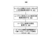
図4は、本発明の一例示的実施形態によるハプティック出力装置に対応付けられたユーザ入力要素を制御するための機能400の流れ図を示す。場合によっては、図4(および以下の図5)の流れ図の機能は、メモリまたは他のコンピュータ可読または有形媒体に格納されたソフトウェアによって実現され、プロセッサによって実行され得る。他の複数の実施形態において、この機能は、ハードウェア(例えば、特定用途向け集積回路(ASIC:application specific integrated circuit)を用いて)、プログラマブルゲートアレイ(PGA:programmable gate array)、フィールドプログラマブルゲートアレイ(FPGA:field programmable gate array)、等々)、またはハードウェアおよびソフトウェアのいずれかの組み合わせによって実施され得る。 FIG. 4 illustrates a flow diagram of a
初めに、410において、機能400は、ハプティック出力装置に対応付けられたユーザ入力要素のための位置の一次および二次範囲を規定し得る。次に、420において、機能400は、ハプティック出力装置に対応付けられたユーザ入力要素のための位置の境界範囲を規定し得る。この境界範囲は、一次および二次範囲の各々に部分的に重なる。これら種々の範囲の規定後、430において、機能400はユーザ入力要素の位置を監視する。最後に、440において、ユーザ入力要素が境界範囲内の位置に入ると、ハプティック効果(単数または複数)がレンダリングされ得る。ここで、ハプティック効果(単数または複数)は、ユーザ入力要素の位置を一方の二次範囲内まで拡張し得る。また、ハプティック効果(単数または複数)をレンダリングするためのハプティック命令は、ゲームアプリケーションなどのソフトウェアアプリケーションによって生成され得る。機能400を用いることによって、ユーザ入力要素の範囲および機能が拡張され、より広範囲のハプティック効果をエンドユーザに知覚させることができる。 Initially, at 410, function 400 may define a primary and secondary range of positions for a user input element associated with a haptic output device. Next, at 420, the
図5は、本発明の別の例示的実施形態によるハプティック出力装置に対応付けられたユーザ入力要素を制御するための機能500の流れ図を示す。 FIG. 5 illustrates a flow diagram of a
最初に、510において、コントローラのユーザ入力要素が初期化され得る。ここで、機能500は、ユーザ入力要素のための位置および範囲情報を最初に設定し得る。例えば、一次範囲、二次範囲(単数または複数)、および境界範囲(単数または複数)が最初に設定され得る。場合によっては、これらの値は、最大外方位置から接地位置までのユーザ入力装置の移動に基づき、算出され得る。 Initially, at 510, a user input element of the controller may be initialized. Here, the
次に、520において、機能500は、ユーザ入力要素のためのプロファイルを算出する。算出されたプロファイルは、ユーザ入力装置の各位置をADC値にマッピングし得る。例えば、520の算出されたプロファイルは、ユーザ入力装置の各位置を0と255の間のADC値にマッピングし得る。 Next, at 520, the
算出されるプロファイルは、増加または減少プロファイルのどちらかを利用し得る。例えば、ユーザ入力値の位置が8ビットADCデータから読み出されると、増加プロファイルは値[0,255]を生成する。同様に、8ビットADCデータから読み出されると、減少プロファイルは値[255,0]を生成する。 The calculated profile may utilize either an increasing or decreasing profile. For example, when the position of the user input value is read from the 8-bit ADC data, the increasing profile produces the value [0,255]. Similarly, when read from 8-bit ADC data, the depletion profile produces the value [255,0].
その後、530において、機能500は、正規化(標準化)プロファイルを算出する。この正規化プロファイルは、二次および/または境界範囲をADCデータから除去することによって算出され得る。例えば、530の算出された正規化プロファイルは、ユーザ入力装置の、二次および/または境界位置以外の、各位置を0と255の間のADC値にマッピングし得る。 Thereafter, at 530, the
場合によっては、ユーザ入力要素の休止位置はさまざまな時点において変化し得る。例えば、さまざまなユーザ入力装置の使用後、ユーザ対話が除かれたときに、これらユーザ入力装置のうちのいくつかは同じ休止位置に戻らないこともある。そのような場合、機能500は、540において、このようなユーザ入力要素のために算出されたプロファイルおよび算出された正規化プロファイルを調整し得る。したがって、ユーザ入力要素の位置を監視しているときは、変化した休止位置(単数または複数)が考慮され得る。 In some cases, the rest position of the user input element may change at various times. For example, after using various user input devices, some of these user input devices may not return to the same rest position when the user interaction is removed. In such a case, function 500 may adjust the calculated profile and the calculated normalized profile for such user input elements at 540. Thus, the changed rest position(s) may be taken into account when monitoring the position of the user input element.
図6は、本発明の一例示的実施形態による、トリガ610が移動する開放拡張移動範囲620を作る外側ばね600を含み、トリガ610がこの開放拡張移動範囲620の外側の最大開位置にあるときのコントローラを示す。より具体的には、図6は、トリガ610を開放拡張移動範囲620の外側の最大開位置に保持する外側ばね600を含むコントローラを示す。力がトリガ610に加わると、外側ばね600はトリガ610を開放拡張移動範囲620まで回転または別の動きをさせることができる。図6は、図601および図602を含む。図601においては、図6の図平面に垂直な軸線に沿ってトリガ610を引くことも押すこともできるので、トリガ610は開放拡張移動範囲620の外側の最大開位置にある。図602において、トリガ610は、開放拡張移動範囲620の内側の最大開位置にある。ここで、トリガ610を引き戻すことはできるが、図6の図平面に垂直な軸線に沿って更に押し出すことはできないので、トリガ610は開放拡張移動範囲620内で更に拡張される。図示の実施形態において、外側ばね600はハプティック減少防止用構成要素の一例であり、トリガ610と外側回転ハードストップ、またはコントローラのハウジングの外側部分、との間に位置付けられる。ユーザは、空間化ハプティック効果を受けているときに自分の指をコントローラのトリガ上に軽く載せておくことができるので、拡張移動範囲の外側の最大開位置は空間化のために重要であり得る。トリガ(トリガ610など)が開放拡張移動範囲(開放拡張移動範囲620など)の外側の最大開位置にあるときにトリガハプティック効果の大きさを増大するために、トリガを外側ばね(外側ばね600など)によって偏移させることができるので、開放拡張移動範囲の外側の最大開位置にあるときに、トリガに加えられた力に対する応答として、トリガは拡張移動範囲内で移動可能である。 FIG. 6 includes an outer spring 600 that creates an open expanded travel range 620 in which the
図601は、トリガ610が開放拡張移動範囲620の外側の最大開位置にあるときに、トリガ610が外側回転ハードストップに、またはコントローラのハウジングの外側部分に、静止またはその他の接触をしないように、外側ばね600がトリガ610を或る位置に保持しているコントローラの図である。換言すると、外側ばね600は、開放拡張移動範囲620を作る。ここで、開放拡張移動範囲620は、対象モータまたはアクチュエータが発生させた力がトリガ610に加えられたことへの応答として、トリガ610がその内部で回転、またはその他の動きをすることができる、範囲である。開放拡張移動範囲620を作ることによって、トリガ610に加えられた力への応答として、トリガ610が回転、またはその他の動きをすると、外側ばね600は、トリガ610が外側回転ハードストップに、またはハウジングの外側部分に、乗り上げることを防止できる。これにより、トリガ610において知覚されるトリガハプティック効果(例えば、運動感覚ハプティック効果)の規模を増大できる。図示の実施形態において、外側ばね600は、レバーアーム605を含む片持ちばねである。トリガ610を上記位置に保持するために、レバーアーム605はトリガ610に押し当たる、または別様に接触する。一代替実施形態において、外側ばね600は、トリガ610に押し当たる、または別様に接触する、圧縮ばね、付勢ばね、または何らか他の種類のばね、にすることができる。さまざまな種類のばねが使用され得るが、各実施形態はそのように限定されるものではなく、他の変形機構も使用され得る。 FIG. 601 illustrates that when the
図602は、対象モータまたはアクチュエータが力をトリガ610に加え、この力への応答として、トリガ610が回転、またはその他の動きをする、コントローラの図である。図6の図602に示されているように、トリガ610は開放拡張移動範囲620内まで回転、またはその他の動きをし、開放拡張移動範囲620の少なくとも一部を占める。図示の実施形態において、トリガ610はレバーアーム605に押し当たる、または別様に接触する。これにより、レバーアーム605が動かされるので、トリガ610は拡張移動範囲620内まで回転またはその他の動きをすることができる。外側ばね600が圧縮ばね、偏倚ばね、または別種のばねである一代替実施形態において、トリガ610は外側ばね600に押し当たる、または別様に接触できる。これにより、外側ばね600を動かすことができるので、トリガ610は開放拡張移動範囲620内まで回転またはその他の動きをすることができる。 FIG. 602 is a diagram of a controller in which a subject motor or actuator applies a force to a
一代替実施形態においては、外側ばね600を内側ばねに交換できる。内側ばねは、トリガ610と内側回転ハードストップ、またはコントローラのハウジングの内側部分、との間に位置付け可能である。更に、トリガ610が外側回転ハードストップ、またはコントローラのハウジングの外側部分に静止またはその他の接触をしないように(すなわち、拡張移動範囲620が作られるように)、内側ばねはトリガ610を引っ張ることができる。この代替実施形態において、トリガ610が内側の回転ハードストップに、またはコントローラのハウジングの内側部分に、静止しているように、またはそこにその他の接触をしているように、トリガ610を引っ張ることを回避するために、内側ばねの剛性を算出できる。 In an alternative embodiment, the outer spring 600 can be replaced with an inner spring. The inner spring can be positioned between the
図7は、本発明の一例示的実施形態による、閉鎖拡張移動範囲730を作る拡張フレーム700を含み、トリガ710がこの閉鎖拡張移動範囲730の外側の最大閉位置にあるときにトリガ710をこの閉鎖拡張移動範囲730内で移動させるコントローラを示す。図示の実施形態において、拡張フレーム700はハプティック減少防止用構成要素の一例であり、更にはコントローラのハウジングの外側部分の拡張部分である。上述のように、標準的なトリガ設計においては、トリガ(トリガ710など)が最大閉位置にあるとき(例えば、ユーザがトリガを完全に押し込んでトリガがハウジングの内側部分に乗り上げているとき)、トリガハプティック効果は大幅に減少され得る。トリガが閉鎖拡張移動範囲の外側の最大閉位置にあるときにトリガハプティック効果を増大するために、拡張フレーム(拡張フレーム700など)は、トリガを動かす物体(物体720など)のための接地位置として使用可能である。この状況においては、トリガが閉鎖拡張移動範囲の外側の最大閉位置まで完全に動いたときでさえ、トリガは依然として物体に逆らって動くことができ、かなりのハプティックフィードバック感覚をトリガにおいて発生させることができる。 FIG. 7 includes an
図7は、図701および図702を含む。図701は、物体720(例えば、ユーザの指)がトリガ710を押した、引いた、または別様に動かしたときのコントローラの図であり、物体720は拡張フレーム700に乗り上げている(すなわち、底止している)。物体720が拡張フレーム700に乗り上げているので、トリガ710が閉鎖拡張移動範囲730の外側の最大閉位置にあるとき、トリガ710は内側回転ハードストップに、またはコントローラのハウジングの内側部分に静止またはその他の接触をしていない。換言すると、拡張フレーム700は閉鎖拡張移動範囲730を作る。この閉鎖拡張移動範囲730は、対象モータまたはアクチュエータが発生させてトリガ710に加えた力への応答として、トリガ710がその中で回転またはその他の動きをすることができる、範囲である。閉鎖拡張移動範囲730を作ることによって、拡張フレーム700は、トリガ710に加えられた力への応答として、トリガ710が回転またはその他の動きをするときに、トリガ710が内側回転ハードストップに、またはハウジングの内側部分に、乗り上げることを防止できる。これにより、トリガ710において知覚されるトリガハプティック効果(例えば、運動感覚ハプティック効果)の大きさを増大できる。 FIG. 7 includes FIGS. 701 and 702. FIG. 701 is a diagram of a controller when an object 720 (eg, a user's finger) pushes, pulls, or otherwise moves a trigger 710, the
図702は、対象モータまたはアクチュエータが力をトリガ710に加え、この力への応答として、トリガ710が回転、またはその他の動きをする、コントローラの図である。図7の図702に示されているように、トリガ710は、閉鎖拡張移動範囲730内まで回転、またはその他の動きをし、閉鎖拡張移動範囲730の少なくとも一部を占める。 FIG. 702 is a diagram of a controller in which a target motor or actuator applies a force to a trigger 710 and the trigger 710 rotates or otherwise moves in response to the force. As shown in FIG. 702 of FIG. 7, the trigger 710 rotates or otherwise moves into the closed expansion travel range 730 and occupies at least a portion of the closed expansion travel range 730.
一代替実施形態において、拡張フレーム700は内側ばねに交換可能である。内側ばねは、トリガ710と内側回転ハードストップ、またはコントローラのハウジングの内側部分、との間に位置付け可能である。更に、トリガ710が内側回転ハードストップに、またはコントローラのハウジングの内側部分に静止またはその他の接触をしないように(すなわち、閉鎖拡張移動範囲730が作られるように)、物体720がトリガ710を押した、引いた、または別様に動かしたときに、内側ばねはトリガ710を押すことができる。この代替実施形態において、トリガ710が内側回転ハードストップに、またはコントローラのハウジングの内側部分に静止またはその他の接触をすることを防止するために十分な抵抗を提供するために、内側ばねの剛性を算出できる。 In an alternative embodiment, the
図8は、本発明の各実施形態での使用に適したコントローラ800の機能ブロック図を示す。 FIG. 8 shows a functional block diagram of a
図8に示されているように、コントローラ800は、種々のユーザ入力要素を1つ以上含み得る。ユーザ入力要素は、ホストコンピュータ804との対話のためにユーザによって操作されるいずれかのインタフェース装置を指し得る。例示的ユーザ入力要素として、アナログまたはデジタルジョイスティック810、ボタン814、トリガ818、等々が挙げられる。当業者によって理解されるように、1つ以上のユーザ入力要素の各々はコントローラ800上に含まれ得る。例えば、トリガ818についての本説明は、コントローラ800を単一のトリガに限定するものではない。同様に、当業者は、複数のアナログまたはデジタルスティック、ボタン、および他のユーザ入力要素が使用され得ることを理解されるであろう。 As shown in FIG. 8,
コントローラ800は、ローカルプロセッサ808を含み得る。ローカルプロセッサ808は、接続805を介して、ホストコンピュータ804とコマンドおよびデータをやり取りし得る。接続805は、当業者には公知の1つ以上の通信プロトコルを用いた有線または無線接続にし得る。場合によっては、コントローラ800は代替的に、ローカルプロセッサ808を含まないように構成され得る。ここで、コントローラ800からの入力/出力信号は、ホストコンピュータ804によって直接操作および処理され得る。ホストコンピュータ804はゲーム装置コンソールでもよく、ディスプレイ装置806はゲーム装置コンソールに作動的に結合されたスクリーンでもよい。場合によっては、ホストコンピュータ804とディスプレイ装置806とは単一の装置に組み合わされ得る。
コントローラ800は、ユーザの手が通常置かれるハウジング802の場所に作動的に結合された1つ以上の汎用または鳴動アクチュエータ822、824と同様に、そのユーザ入力要素の各々を直接駆動するための対象アクチュエータ812、816、820(例えば、モータ)を含み得る。より具体的には、アナログまたはデジタルスティック810は、そこに作動的に結合された対象アクチュエータまたはモータ812を含み、ボタン814は、そこに作動的に結合された対象アクチュエータまたはモータ816を含み、トリガ818は、そこに作動的に結合された対象アクチュエータまたはモータ820を含む。複数の対象アクチュエータに加え、コントローラ800は、そのユーザ入力要素の各々に作動的に結合された位置センサを含む。より具体的には、アナログまたはデジタルスティック810は、そこに作動的に結合された位置センサ811を含み、ボタン814は、そこに作動的に結合された位置センサ815を含み、トリガ818は、そこに作動的に結合された位置センサ819を含む。ローカルプロセッサ808は、アナログまたはデジタルスティック810、ボタン814、およびトリガ818のそれぞれの位置センサ811、815、819と同様に対象アクチュエータ812、816および820に作動的に結合される。位置センサ811、815、819から受信された信号への応答として、ローカルプロセッサ808は、方向付けられた、または的を絞った、運動感覚効果をアナログまたはデジタルスティック810、ボタン814、およびトリガ818にそれぞれ直接提供するべく対象アクチュエータ812、816、820に命令する。このような的を絞った運動感覚効果は、汎用アクチュエータ822、824がコントローラの本体全体に沿って発生させる汎用または鳴動ハプティック効果から識別可能または区別可能である。集合的ハプティック効果は、複数の様式が同時に関与するので(例えば、ビデオ、オーディオ、およびハプティック)より大きな没入感覚をユーザに提供する。 The
図9Aおよび図9Bは、本発明の各実施形態での使用に適したコントローラ900の異なる図を示す。図9Aおよび図9Bに示されているように、コントローラ900は、ハウジング902、アナログまたはデジタルジョイスティック910、ボタン(単数または複数)914、トリガ918、および鳴動アクチュエータ922および924など、さまざまな構成要素を含み得る。 9A and 9B show different views of a
ハウジング902は、ユーザによるコントローラ900の把持を容易に受け止めるべく形作られる。コントローラ900は、コントローラの一例示的実施形態であり、本発明の各実施形態は他のコントローラ形状にも容易に適用され得る。 The
したがって、本発明の各実施形態はユーザ入力要素の範囲および機能を拡張する。また、ユーザ入力要素の複数の規定可能な位置においてハプティック効果をレンダリングすることによって、より広範囲のハプティック効果を実現させることができる。 Thus, embodiments of the present invention extend the scope and functionality of user input elements. Also, a wider range of haptic effects can be achieved by rendering the haptic effect at multiple definable positions of the user input element.
本発明は、前述のように、複数のステップを異なる順番で、および/または複数の要素を開示されているものとは異なる構成で、実施され得ることを当業者は容易に理解するであろう。したがって、これら好適な実施形態に基づき本発明を説明してきたが、本発明の趣旨および範囲内に留まりながら、特定の変更例、変形例、および代替構造が明らかであろうことは当業者には明らかであろう。したがって、本発明の範囲を判定するには、添付の特許請求の範囲を参照されるべきである。 One of ordinary skill in the art will readily appreciate that the present invention may be implemented in a plurality of steps in a different order, and/or in a different arrangement than the disclosed elements, as described above. .. Thus, while the present invention has been described in terms of these preferred embodiments, those skilled in the art will appreciate that certain modifications, variations, and alternative constructions may be apparent while remaining within the spirit and scope of the invention. Would be obvious. Reference should therefore be made to the appended claims for determining the scope of the invention.
Claims (41)
Translated fromJapanese前記ハプティック出力装置に対応付けられた前記ユーザ入力要素のために位置の一次および二次範囲を規定するステップと、
前記ハプティック出力装置に対応付けられた前記ユーザ入力要素のために位置の境界範囲を規定するステップであって、前記境界範囲は前記一次および二次範囲の各々に部分的に重なる、ステップと、
前記ユーザ入力要素の位置を監視するステップと、
前記ユーザ入力要素が前記境界範囲内の位置に入ると、その応答として前記ハプティック効果をレンダリングするステップと、
を含む方法。A method for rendering a haptic effect on a user input element associated with a haptic output device, the method comprising:
Defining primary and secondary ranges of position for the user input element associated with the haptic output device;
Defining a bounding range of locations for the user input element associated with the haptic output device, the bounding range partially overlapping each of the primary and secondary ranges;
Monitoring the position of the user input element,
Rendering the haptic effect in response to the user input element entering a position within the bounds.
Including the method.
前記プロセッサによって実行されるプログラムを格納するメモリと、
を備えた装置であって、前記プログラムは、
ハプティック出力装置に対応付けられたユーザ入力要素のための位置の一次および二次範囲を規定することと、
前記ハプティック出力装置に対応付けられた前記ユーザ入力要素のための位置の境界範囲を規定することであって、前記境界範囲は前記一次および二次範囲の各々に部分的に重なる、ことと、
前記ユーザ入力要素の位置を監視することと、
前記ユーザ入力要素が前記境界範囲内の位置に入ると、その応答としてハプティック効果をレンダリングすることと、
のための命令を含む、装置。A processor,
A memory storing a program executed by the processor,
An apparatus comprising:
Defining primary and secondary ranges of positions for user input elements associated with the haptic output device;
Defining a boundary range of locations for the user input element associated with the haptic output device, the boundary range partially overlapping each of the primary and secondary ranges;
Monitoring the position of the user input element;
Rendering a haptic effect in response when the user input element enters a position within the bounds.
Device, including instructions for.
ハプティック出力装置に対応付けられたユーザ入力要素のための位置の一次および二次範囲を規定するステップと、
前記ハプティック出力装置に対応付けられた前記ユーザ入力要素のための位置の境界範囲を規定するステップであって、前記境界範囲は前記一次および二次範囲の各々に部分的に重なる、ステップと、
前記ユーザ入力要素の位置を監視するステップと、
前記ユーザ入力要素が前記境界範囲内の位置に入ると、その応答としてハプティック効果をレンダリングするステップと、
のための命令を含む、コンピュータ可読記憶媒体。A non-transitory computer-readable storage medium storing a program configured to be executed by a processor, the program comprising:
Defining primary and secondary ranges of position for user input elements associated with the haptic output device;
Defining a boundary range of locations for the user input element associated with the haptic output device, the boundary range partially overlapping each of the primary and secondary ranges;
Monitoring the position of the user input element,
Rendering a haptic effect in response to the user input element entering a position within the bounds, and
A computer-readable storage medium including instructions for.
前記ハプティック出力装置に対応付けられた前記ユーザ入力要素のための、位置の一次範囲、位置の二次範囲、および位置の境界範囲を含む位置および範囲情報を規定するステップであって、位置の前記境界範囲は、位置の前記一次範囲および位置の前記二次範囲の各々に部分的に重なる、ステップと、
前記ユーザ入力要素が位置の前記境界範囲内の1つまたは複数の位置に入ると、その応答としてハプティック効果をレンダリングするステップと、
を含む方法。A method for controlling a user input element associated with a haptic output device, the method comprising:
Defining position and range information, including a primary range of positions, a secondary range of positions, and a boundary range of positions, for the user input element associated with the haptic output device, the method comprising: A boundary range partially overlaps each of the primary range of positions and the secondary range of positions;
Rendering a haptic effect in response to the user input element entering one or more locations within the boundary of locations,
Including the method.
ハプティック出力装置に対応付けられたユーザ入力要素のための、位置の一次範囲、位置の二次範囲、および位置の境界範囲を含む位置および範囲情報を規定するステップであって、位置の前記境界範囲は、位置の前記一次範囲および位置の前記二次範囲の各々に部分的に重なる、ステップと、
前記ユーザ入力要素が位置の前記境界範囲内の1つまたは複数の位置に入ると、その応答としてハプティック効果をレンダリングするステップと、
のための命令を含む、コンピュータ可読記憶媒体。A non-transitory computer-readable storage medium storing a program configured to be executed by a processor, the program comprising:
Defining position and range information, including a primary range of positions, a secondary range of positions, and a boundary range of positions, for a user input element associated with a haptic output device, said boundary range of positions Partially overlaps each of the primary range of positions and the secondary range of positions;
Rendering a haptic effect in response to the user input element entering one or more locations within the boundary of locations,
A computer-readable storage medium including instructions for.
前記プロセッサによって実行されるプログラムを格納するメモリと、
を備えた装置であって、前記プログラムは、
ハプティック出力装置に対応付けられたユーザ入力要素のための、位置の一次範囲、位置の二次範囲、および位置の境界範囲を含む位置および範囲情報を規定することであって、位置の前記境界範囲は、位置の前記一次範囲および位置の前記二次範囲の各々に部分的に重なる、ことと、
前記ユーザ入力要素が位置の前記境界範囲内の1つまたは複数の位置に入ると、その応答としてハプティック効果をレンダリングすることと、
のための命令を含む、装置。A processor,
A memory storing a program executed by the processor,
An apparatus comprising:
Defining a position and range information, including a primary range of position, a secondary range of position, and a boundary range of position, for a user input element associated with a haptic output device, said boundary range of position being Partially overlaps each of the primary range of positions and the secondary range of positions;
Rendering a haptic effect in response to the user input element entering one or more locations within the boundary of locations;
Device, including instructions for.
Applications Claiming Priority (3)
| Application Number | Priority Date | Filing Date | Title |
|---|---|---|---|
| US201462096251P | 2014-12-23 | 2014-12-23 | |
| US62/096,251 | 2014-12-23 | ||
| PCT/US2015/000225WO2016105495A1 (en) | 2014-12-23 | 2015-12-23 | Position control of a user input element associated with a haptic output device |
Publications (2)
| Publication Number | Publication Date |
|---|---|
| JP2018501553A JP2018501553A (en) | 2018-01-18 |
| JP6735747B2true JP6735747B2 (en) | 2020-08-05 |
Family
ID=56128328
Family Applications (5)
| Application Number | Title | Priority Date | Filing Date |
|---|---|---|---|
| JP2017522604AExpired - Fee RelatedJP6781697B2 (en) | 2014-12-23 | 2015-12-23 | Media-driven haptics |
| JP2017526501ACeasedJP2018500960A (en) | 2014-12-23 | 2015-12-23 | Haptic output device architecture and communication protocol |
| JP2017526503AActiveJP6908242B6 (en) | 2014-12-23 | 2015-12-23 | Reduced feedback on user input elements associated with haptic output devices |
| JP2017526640AActiveJP6735747B2 (en) | 2014-12-23 | 2015-12-23 | Position control of user input element associated with haptic output device |
| JP2020082475APendingJP2020126685A (en) | 2014-12-23 | 2020-05-08 | Feedback reduction for user input element associated with haptic output device |
Family Applications Before (3)
| Application Number | Title | Priority Date | Filing Date |
|---|---|---|---|
| JP2017522604AExpired - Fee RelatedJP6781697B2 (en) | 2014-12-23 | 2015-12-23 | Media-driven haptics |
| JP2017526501ACeasedJP2018500960A (en) | 2014-12-23 | 2015-12-23 | Haptic output device architecture and communication protocol |
| JP2017526503AActiveJP6908242B6 (en) | 2014-12-23 | 2015-12-23 | Reduced feedback on user input elements associated with haptic output devices |
Family Applications After (1)
| Application Number | Title | Priority Date | Filing Date |
|---|---|---|---|
| JP2020082475APendingJP2020126685A (en) | 2014-12-23 | 2020-05-08 | Feedback reduction for user input element associated with haptic output device |
Country Status (6)
| Country | Link |
|---|---|
| US (7) | US10613628B2 (en) |
| EP (4) | EP3194040A4 (en) |
| JP (5) | JP6781697B2 (en) |
| KR (3) | KR20170096100A (en) |
| CN (4) | CN107073332A (en) |
| WO (4) | WO2016105493A1 (en) |
Families Citing this family (67)
| Publication number | Priority date | Publication date | Assignee | Title |
|---|---|---|---|---|
| US9164587B2 (en) | 2013-11-14 | 2015-10-20 | Immersion Corporation | Haptic spatialization system |
| US9619029B2 (en)* | 2013-11-14 | 2017-04-11 | Immersion Corporation | Haptic trigger control system |
| US10185396B2 (en) | 2014-11-12 | 2019-01-22 | Immersion Corporation | Haptic trigger modification system |
| US9632582B2 (en) | 2014-12-22 | 2017-04-25 | Immersion Corporation | Magnetic suspension system for touch screens and touch surfaces |
| US9589432B2 (en)* | 2014-12-22 | 2017-03-07 | Immersion Corporation | Haptic actuators having programmable magnets with pre-programmed magnetic surfaces and patterns for producing varying haptic effects |
| JP2016136306A (en)* | 2015-01-23 | 2016-07-28 | ソニー株式会社 | Information processor, information processing method and program |
| CN105553458B (en)* | 2015-12-28 | 2018-07-03 | 哈尔滨工业大学 | A kind of driving method of the shape-memory polymer based on sound control |
| JP6625726B2 (en) | 2016-03-04 | 2019-12-25 | 株式会社ソニー・インタラクティブエンタテインメント | Control device and control program |
| JP6626576B2 (en) | 2016-07-21 | 2019-12-25 | 株式会社ソニー・インタラクティブエンタテインメント | Operation device and control system |
| EP3493030B1 (en) | 2016-07-26 | 2021-06-23 | Sony Interactive Entertainment Inc. | Operation device and operation device control method |
| US11344797B2 (en) | 2016-07-26 | 2022-05-31 | Sony Interactive Entertainment Inc. | Information processing system, operation device, and operation device control method with multi-mode haptic feedback |
| US10732714B2 (en) | 2017-05-08 | 2020-08-04 | Cirrus Logic, Inc. | Integrated haptic system |
| US11259121B2 (en) | 2017-07-21 | 2022-02-22 | Cirrus Logic, Inc. | Surface speaker |
| WO2019064518A1 (en) | 2017-09-29 | 2019-04-04 | 株式会社ソニー・インタラクティブエンタテインメント | Operation device and control apparatus therefor |
| JP6932055B2 (en)* | 2017-10-03 | 2021-09-08 | アルプスアルパイン株式会社 | Tactile presentation system and tactile presentation device |
| JP6949982B2 (en) | 2017-10-27 | 2021-10-13 | 株式会社ソニー・インタラクティブエンタテインメント | Operation device |
| US10620704B2 (en) | 2018-01-19 | 2020-04-14 | Cirrus Logic, Inc. | Haptic output systems |
| US10455339B2 (en) | 2018-01-19 | 2019-10-22 | Cirrus Logic, Inc. | Always-on detection systems |
| US10877562B2 (en)* | 2018-03-02 | 2020-12-29 | Htc Corporation | Motion detection system, motion detection method and computer-readable recording medium thereof |
| US11139767B2 (en) | 2018-03-22 | 2021-10-05 | Cirrus Logic, Inc. | Methods and apparatus for driving a transducer |
| US10795443B2 (en) | 2018-03-23 | 2020-10-06 | Cirrus Logic, Inc. | Methods and apparatus for driving a transducer |
| US10820100B2 (en) | 2018-03-26 | 2020-10-27 | Cirrus Logic, Inc. | Methods and apparatus for limiting the excursion of a transducer |
| US10832537B2 (en) | 2018-04-04 | 2020-11-10 | Cirrus Logic, Inc. | Methods and apparatus for outputting a haptic signal to a haptic transducer |
| TWM565594U (en)* | 2018-04-27 | 2018-08-21 | 正崴精密工業股份有限公司 | Trigger mechanism of game controller |
| US11069206B2 (en) | 2018-05-04 | 2021-07-20 | Cirrus Logic, Inc. | Methods and apparatus for outputting a haptic signal to a haptic transducer |
| US11269415B2 (en) | 2018-08-14 | 2022-03-08 | Cirrus Logic, Inc. | Haptic output systems |
| CN112585982B (en)* | 2018-08-30 | 2024-04-16 | 索尼公司 | Transmitting apparatus, transmitting method, receiving apparatus, and receiving method |
| US10345758B2 (en)* | 2018-10-07 | 2019-07-09 | Rising Star Pathway, a California Corporation | Processor controlled energy harvester based on oscillating weight type energy collectors |
| GB201817495D0 (en) | 2018-10-26 | 2018-12-12 | Cirrus Logic Int Semiconductor Ltd | A force sensing system and method |
| EP3896555B1 (en)* | 2018-12-13 | 2023-09-13 | Sony Group Corporation | Information processing device, information processing system, information processing method, and program |
| US10955955B2 (en) | 2019-03-29 | 2021-03-23 | Cirrus Logic, Inc. | Controller for use in a device comprising force sensors |
| US12176781B2 (en) | 2019-03-29 | 2024-12-24 | Cirrus Logic Inc. | Methods and systems for estimating transducer parameters |
| US12035445B2 (en) | 2019-03-29 | 2024-07-09 | Cirrus Logic Inc. | Resonant tracking of an electromagnetic load |
| US11509292B2 (en) | 2019-03-29 | 2022-11-22 | Cirrus Logic, Inc. | Identifying mechanical impedance of an electromagnetic load using least-mean-squares filter |
| US11644370B2 (en) | 2019-03-29 | 2023-05-09 | Cirrus Logic, Inc. | Force sensing with an electromagnetic load |
| US10726683B1 (en) | 2019-03-29 | 2020-07-28 | Cirrus Logic, Inc. | Identifying mechanical impedance of an electromagnetic load using a two-tone stimulus |
| US10828672B2 (en) | 2019-03-29 | 2020-11-10 | Cirrus Logic, Inc. | Driver circuitry |
| US10992297B2 (en) | 2019-03-29 | 2021-04-27 | Cirrus Logic, Inc. | Device comprising force sensors |
| JP7581241B2 (en)* | 2019-05-10 | 2024-11-12 | マジック リープ, インコーポレイテッド | Method and system for tactile beamforming and tactile effects in a handheld controller - Patents.com |
| US11150733B2 (en) | 2019-06-07 | 2021-10-19 | Cirrus Logic, Inc. | Methods and apparatuses for providing a haptic output signal to a haptic actuator |
| US10976825B2 (en)* | 2019-06-07 | 2021-04-13 | Cirrus Logic, Inc. | Methods and apparatuses for controlling operation of a vibrational output system and/or operation of an input sensor system |
| WO2020254788A1 (en) | 2019-06-21 | 2020-12-24 | Cirrus Logic International Semiconductor Limited | A method and apparatus for configuring a plurality of virtual buttons on a device |
| US10951951B2 (en)* | 2019-07-30 | 2021-03-16 | Sony Interactive Entertainment Inc. | Haptics metadata in a spectating stream |
| US11853479B2 (en)* | 2019-09-16 | 2023-12-26 | Jonah B Saunders | Haptic garment |
| US11408787B2 (en) | 2019-10-15 | 2022-08-09 | Cirrus Logic, Inc. | Control methods for a force sensor system |
| US11380175B2 (en) | 2019-10-24 | 2022-07-05 | Cirrus Logic, Inc. | Reproducibility of haptic waveform |
| US12276687B2 (en) | 2019-12-05 | 2025-04-15 | Cirrus Logic Inc. | Methods and systems for estimating coil impedance of an electromagnetic transducer |
| GB2592462B (en)* | 2019-12-05 | 2022-11-09 | Cirrus Logic Int Semiconductor Ltd | Methods and systems for estimating coil impedance of an electromagnetic transducer |
| US11545951B2 (en) | 2019-12-06 | 2023-01-03 | Cirrus Logic, Inc. | Methods and systems for detecting and managing amplifier instability |
| CN111111157B (en)* | 2019-12-20 | 2023-12-01 | 瑞声科技(新加坡)有限公司 | Motor touch signal generation method and motor touch signal generation interface |
| US11662821B2 (en) | 2020-04-16 | 2023-05-30 | Cirrus Logic, Inc. | In-situ monitoring, calibration, and testing of a haptic actuator |
| US12244253B2 (en) | 2020-04-16 | 2025-03-04 | Cirrus Logic Inc. | Restricting undesired movement of a haptic actuator |
| US11698680B2 (en)* | 2020-06-23 | 2023-07-11 | Immersion Corporation | Methods and systems for decoding and rendering a haptic effect associated with a 3D environment |
| KR20210114059A (en)* | 2020-06-30 | 2021-09-17 | 바이두 온라인 네트웍 테크놀러지 (베이징) 캄파니 리미티드 | Video processing methods, devices, electronic devices and storage media |
| KR102232438B1 (en) | 2020-07-14 | 2021-03-26 | (주)나모 | Card payment system for local voucher utilization and regional economy activation and Method of the Same |
| US11933822B2 (en) | 2021-06-16 | 2024-03-19 | Cirrus Logic Inc. | Methods and systems for in-system estimation of actuator parameters |
| US11765499B2 (en) | 2021-06-22 | 2023-09-19 | Cirrus Logic Inc. | Methods and systems for managing mixed mode electromechanical actuator drive |
| US11908310B2 (en) | 2021-06-22 | 2024-02-20 | Cirrus Logic Inc. | Methods and systems for detecting and managing unexpected spectral content in an amplifier system |
| CN113842634B (en)* | 2021-09-27 | 2024-02-27 | 歌尔科技有限公司 | Force feedback control method and device for trigger button, electronic product and medium |
| CN113836385B (en)* | 2021-09-27 | 2024-06-07 | 歌尔股份有限公司 | Motor parameter setting method, apparatus and computer readable storage medium |
| US11552649B1 (en) | 2021-12-03 | 2023-01-10 | Cirrus Logic, Inc. | Analog-to-digital converter-embedded fixed-phase variable gain amplifier stages for dual monitoring paths |
| JP2023148852A (en)* | 2022-03-30 | 2023-10-13 | 株式会社栗本鐵工所 | Control device, control method, haptic feedback system, and computer program |
| DE112023001742T5 (en)* | 2022-03-31 | 2025-02-27 | Sony Group Corporation | DECODING DEVICE, DECODING METHOD AND DECODING PROGRAM |
| CN115291726B (en)* | 2022-08-09 | 2023-11-07 | 中国电信股份有限公司 | Haptic simulation method, haptic simulation device, haptic simulation system, storage medium and electronic device |
| US12436617B2 (en)* | 2023-06-26 | 2025-10-07 | Adeia Guides Inc. | Systems and methods for balancing haptics and graphics rendering processing with content adaptation |
| CN120296307A (en)* | 2024-01-11 | 2025-07-11 | 维沃移动通信有限公司 | Method, device and related equipment for processing tactile data |
| US20250306694A1 (en)* | 2024-03-26 | 2025-10-02 | Htc Corporation | Hand gesture tracking device, method, and non-transitory computer readable storage medium thereof |
Family Cites Families (114)
| Publication number | Priority date | Publication date | Assignee | Title |
|---|---|---|---|---|
| US5959613A (en)* | 1995-12-01 | 1999-09-28 | Immersion Corporation | Method and apparatus for shaping force signals for a force feedback device |
| US6028593A (en)* | 1995-12-01 | 2000-02-22 | Immersion Corporation | Method and apparatus for providing simulated physical interactions within computer generated environments |
| US6020876A (en)* | 1997-04-14 | 2000-02-01 | Immersion Corporation | Force feedback interface with selective disturbance filter |
| US6067077A (en) | 1998-04-10 | 2000-05-23 | Immersion Corporation | Position sensing for force feedback devices |
| US6184868B1 (en)* | 1998-09-17 | 2001-02-06 | Immersion Corp. | Haptic feedback control devices |
| EP1185966A1 (en) | 1999-05-12 | 2002-03-13 | Twentieth Century Fox Film Corporation | Simulation system |
| JP2001016658A (en)* | 1999-06-30 | 2001-01-19 | Sony Corp | Radio controller for game machine |
| EP1320024B1 (en)* | 2000-08-23 | 2007-01-24 | Nintendo Co., Limited | Information processor, information storage medium, program, and operating device for game machine |
| US6864877B2 (en)* | 2000-09-28 | 2005-03-08 | Immersion Corporation | Directional tactile feedback for haptic feedback interface devices |
| US6641480B2 (en) | 2001-01-29 | 2003-11-04 | Microsoft Corporation | Force feedback mechanism for gamepad device |
| US6873316B2 (en)* | 2001-02-01 | 2005-03-29 | Cts Corporation | Suppression of cursor control during tactile feedback operation |
| US8010180B2 (en)* | 2002-03-06 | 2011-08-30 | Mako Surgical Corp. | Haptic guidance system and method |
| JP3866163B2 (en) | 2002-07-01 | 2007-01-10 | アルプス電気株式会社 | Game console controller |
| US7970147B2 (en)* | 2004-04-07 | 2011-06-28 | Sony Computer Entertainment Inc. | Video game controller with noise canceling logic |
| CA2783161A1 (en) | 2003-04-15 | 2004-11-25 | D-Box Technologies Inc. | Flexible interface for controlling a motion platform |
| GB0322489D0 (en)* | 2003-09-25 | 2003-10-29 | British Telecomm | Haptics transmission systems |
| US9948885B2 (en) | 2003-12-12 | 2018-04-17 | Kurzweil Technologies, Inc. | Virtual encounters |
| US7283120B2 (en) | 2004-01-16 | 2007-10-16 | Immersion Corporation | Method and apparatus for providing haptic feedback having a position-based component and a predetermined time-based component |
| JP2005332039A (en)* | 2004-05-18 | 2005-12-02 | Alps Electric Co Ltd | Force sense giving type input device |
| US20060220788A1 (en) | 2005-04-04 | 2006-10-05 | Dietz Paul H | Control system for differentiating multiple users |
| EP2380640A3 (en)* | 2005-06-27 | 2011-12-28 | Coactive Drive Corporation | Synchronized vibration device for haptic feedback |
| WO2007030603A2 (en)* | 2005-09-08 | 2007-03-15 | Wms Gaming Inc. | Gaming machine having display with sensory feedback |
| US8568213B2 (en) | 2005-11-04 | 2013-10-29 | Mattel, Inc. | Game unit with controller-determined characters |
| JP5004518B2 (en) | 2006-06-22 | 2012-08-22 | 任天堂株式会社 | GAME DEVICE, GAME PROGRAM, GAME SYSTEM, AND GAME PROCESSING METHOD |
| JP2008015679A (en)* | 2006-07-04 | 2008-01-24 | Sony Computer Entertainment Inc | User interface device and operational sensitivity adjustment method |
| US9370704B2 (en) | 2006-08-21 | 2016-06-21 | Pillar Vision, Inc. | Trajectory detection and feedback system for tennis |
| EP2014341B8 (en) | 2007-07-09 | 2017-08-30 | Sony Interactive Entertainment Inc. | Game Controller |
| JP5183987B2 (en)* | 2007-07-09 | 2013-04-17 | 株式会社ソニー・コンピュータエンタテインメント | GAME DEVICE AND GAME SYSTEM |
| JP4892443B2 (en)* | 2007-07-09 | 2012-03-07 | 株式会社ソニー・コンピュータエンタテインメント | Game controller |
| US20090079690A1 (en)* | 2007-09-21 | 2009-03-26 | Sony Computer Entertainment America Inc. | Method and apparatus for enhancing entertainment software through haptic insertion |
| US9019087B2 (en) | 2007-10-16 | 2015-04-28 | Immersion Corporation | Synchronization of haptic effect data in a media stream |
| US8117364B2 (en)* | 2007-11-13 | 2012-02-14 | Microsoft Corporation | Enhanced protocol and architecture for low bandwidth force feedback game controller |
| JP5016117B2 (en) | 2008-01-17 | 2012-09-05 | アーティキュレイト テクノロジーズ インコーポレーティッド | Method and apparatus for intraoral tactile feedback |
| US8749495B2 (en)* | 2008-09-24 | 2014-06-10 | Immersion Corporation | Multiple actuation handheld device |
| US20100141408A1 (en)* | 2008-12-05 | 2010-06-10 | Anthony Stephen Doy | Audio amplifier apparatus to drive a panel to produce both an audio signal and haptic feedback |
| US8506369B2 (en)* | 2009-01-06 | 2013-08-13 | Immersion Corporation | Programmable game-based haptic enabled gun controller |
| US10564721B2 (en)* | 2009-03-12 | 2020-02-18 | Immersion Corporation | Systems and methods for using multiple actuators to realize textures |
| WO2010118313A1 (en)* | 2009-04-10 | 2010-10-14 | Immerz Inc. | Systems and methods for acousto-haptic speakers |
| US8953029B2 (en) | 2009-05-08 | 2015-02-10 | Sony Computer Entertainment America Llc | Portable device interaction via motion sensitive controller |
| US9370459B2 (en) | 2009-06-19 | 2016-06-21 | Andrew Mahoney | System and method for alerting visually impaired users of nearby objects |
| US9417694B2 (en)* | 2009-10-30 | 2016-08-16 | Immersion Corporation | System and method for haptic display of data transfers |
| US8506405B2 (en)* | 2009-11-06 | 2013-08-13 | Wms Gaming, Inc. | Media processing mechanism for wagering game systems |
| US8542105B2 (en)* | 2009-11-24 | 2013-09-24 | Immersion Corporation | Handheld computer interface with haptic feedback |
| US8540571B2 (en) | 2010-03-31 | 2013-09-24 | Immersion Corporation | System and method for providing haptic stimulus based on position |
| WO2011127379A2 (en) | 2010-04-09 | 2011-10-13 | University Of Florida Research Foundation Inc. | Interactive mixed reality system and uses thereof |
| US8698766B2 (en)* | 2010-04-22 | 2014-04-15 | Maxim Integrated Products, Inc. | System integration of tactile feedback and touchscreen controller for near-zero latency haptics playout |
| US8798534B2 (en)* | 2010-07-09 | 2014-08-05 | Digimarc Corporation | Mobile devices and methods employing haptics |
| KR101166767B1 (en) | 2010-08-06 | 2012-07-31 | 한국과학기술원 | Haptic Feedback Providing Device and Method using Beat Phenomenon and Judgement Method Specific Group based on Beat Phenomenon and Method for Providing Social Network Sevices, Location based Sevices based on Beat Phenomenon |
| HUE055666T2 (en) | 2010-11-23 | 2021-12-28 | Nat Univ Ireland Maynooth | Method and apparatus for sensory substitution |
| KR20140112386A (en)* | 2011-03-17 | 2014-09-23 | 코액티브 드라이브 코포레이션 | Asymmetric and general vibration waveforms from multiple synchronized vibration actuators |
| US9462262B1 (en) | 2011-08-29 | 2016-10-04 | Amazon Technologies, Inc. | Augmented reality environment with environmental condition control |
| US8894491B2 (en)* | 2011-12-09 | 2014-11-25 | Microsoft Corporation | Multi-stage variable resistance trigger |
| US10013857B2 (en) | 2011-12-21 | 2018-07-03 | Qualcomm Incorporated | Using haptic technologies to provide enhanced media experiences |
| US9898119B2 (en) | 2012-02-20 | 2018-02-20 | Sony Mobile Communications Inc. | Touch screen interface with feedback |
| US9715276B2 (en)* | 2012-04-04 | 2017-07-25 | Immersion Corporation | Sound to haptic effect conversion system using multiple actuators |
| JP2013228813A (en)* | 2012-04-24 | 2013-11-07 | Nikon Corp | Electronic apparatus and movement detection method |
| US10852093B2 (en) | 2012-05-22 | 2020-12-01 | Haptech, Inc. | Methods and apparatuses for haptic systems |
| JP6461791B2 (en)* | 2012-08-07 | 2019-01-30 | フィリップス ライティング ホールディング ビー ヴィ | Timed lighting control |
| US9053243B2 (en)* | 2012-10-10 | 2015-06-09 | Google Inc. | Unidirectional and bidirectional communication between a host device and a peripheral device |
| FR2999741B1 (en) | 2012-12-17 | 2015-02-06 | Centre Nat Rech Scient | HAPTIC SYSTEM FOR NON-CONTACT INTERACTING AT LEAST ONE PART OF THE BODY OF A USER WITH A VIRTUAL ENVIRONMENT |
| US9489047B2 (en)* | 2013-03-01 | 2016-11-08 | Immersion Corporation | Haptic device with linear resonant actuator |
| US10521015B2 (en) | 2013-03-01 | 2019-12-31 | Nokia Technologies Oy | Control apparatus for a tactile audio display |
| US8754757B1 (en)* | 2013-03-05 | 2014-06-17 | Immersion Corporation | Automatic fitting of haptic effects |
| US9866924B2 (en) | 2013-03-14 | 2018-01-09 | Immersion Corporation | Systems and methods for enhanced television interaction |
| US9997032B2 (en) | 2013-04-09 | 2018-06-12 | Immersion Corporation | Offline haptic conversion system |
| US9367136B2 (en) | 2013-04-12 | 2016-06-14 | Microsoft Technology Licensing, Llc | Holographic object feedback |
| EP2796965B1 (en)* | 2013-04-22 | 2019-12-18 | Immersion Corporation | Gaming device having a haptic enabled trigger |
| JP2014215850A (en)* | 2013-04-26 | 2014-11-17 | ヤマハ株式会社 | Parameter setting device |
| US9908048B2 (en) | 2013-06-08 | 2018-03-06 | Sony Interactive Entertainment Inc. | Systems and methods for transitioning between transparent mode and non-transparent mode in a head mounted display |
| US9811854B2 (en) | 2013-07-02 | 2017-11-07 | John A. Lucido | 3-D immersion technology in a virtual store |
| EP3014394B1 (en) | 2013-07-05 | 2022-06-22 | Rubin, Jacob A. | Whole-body human-computer interface |
| US9576445B2 (en) | 2013-09-06 | 2017-02-21 | Immersion Corp. | Systems and methods for generating haptic effects associated with an envelope in audio signals |
| US9711014B2 (en) | 2013-09-06 | 2017-07-18 | Immersion Corporation | Systems and methods for generating haptic effects associated with transitions in audio signals |
| US9652945B2 (en) | 2013-09-06 | 2017-05-16 | Immersion Corporation | Method and system for providing haptic effects based on information complementary to multimedia content |
| US9619980B2 (en) | 2013-09-06 | 2017-04-11 | Immersion Corporation | Systems and methods for generating haptic effects associated with audio signals |
| US9630105B2 (en) | 2013-09-30 | 2017-04-25 | Sony Interactive Entertainment Inc. | Camera based safety mechanisms for users of head mounted displays |
| US9619029B2 (en)* | 2013-11-14 | 2017-04-11 | Immersion Corporation | Haptic trigger control system |
| US8767996B1 (en) | 2014-01-06 | 2014-07-01 | Alpine Electronics of Silicon Valley, Inc. | Methods and devices for reproducing audio signals with a haptic apparatus on acoustic headphones |
| WO2015107386A1 (en) | 2014-01-15 | 2015-07-23 | Sony Corporation | Haptic notification on wearables |
| US9551873B2 (en) | 2014-05-30 | 2017-01-24 | Sony Interactive Entertainment America Llc | Head mounted device (HMD) system having interface with mobile computing device for rendering virtual reality content |
| CN106796451B (en) | 2014-07-28 | 2020-07-21 | Ck高新材料有限公司 | Tactile information providing module |
| US9645646B2 (en) | 2014-09-04 | 2017-05-09 | Intel Corporation | Three dimensional contextual feedback wristband device |
| US9799177B2 (en) | 2014-09-23 | 2017-10-24 | Intel Corporation | Apparatus and methods for haptic covert communication |
| US9846484B2 (en)* | 2014-12-04 | 2017-12-19 | Immersion Corporation | Systems and methods for controlling haptic signals |
| US10166466B2 (en) | 2014-12-11 | 2019-01-01 | Elwha Llc | Feedback for enhanced situational awareness |
| US9922518B2 (en) | 2014-12-11 | 2018-03-20 | Elwha Llc | Notification of incoming projectiles |
| US9870718B2 (en) | 2014-12-11 | 2018-01-16 | Toyota Motor Engineering & Manufacturing North America, Inc. | Imaging devices including spacing members and imaging devices including tactile feedback devices |
| US20160170508A1 (en) | 2014-12-11 | 2016-06-16 | Toyota Motor Engineering & Manufacturing North America, Inc. | Tactile display devices |
| US10073516B2 (en) | 2014-12-29 | 2018-09-11 | Sony Interactive Entertainment Inc. | Methods and systems for user interaction within virtual reality scene using head mounted display |
| US9746921B2 (en) | 2014-12-31 | 2017-08-29 | Sony Interactive Entertainment Inc. | Signal generation and detector systems and methods for determining positions of fingers of a user |
| US9843744B2 (en) | 2015-01-13 | 2017-12-12 | Disney Enterprises, Inc. | Audience interaction projection system |
| US10322203B2 (en) | 2015-06-26 | 2019-06-18 | Intel Corporation | Air flow generation for scent output |
| US9851799B2 (en) | 2015-09-25 | 2017-12-26 | Oculus Vr, Llc | Haptic surface with damping apparatus |
| US20170103574A1 (en) | 2015-10-13 | 2017-04-13 | Google Inc. | System and method for providing continuity between real world movement and movement in a virtual/augmented reality experience |
| US20170131775A1 (en) | 2015-11-10 | 2017-05-11 | Castar, Inc. | System and method of haptic feedback by referral of sensation |
| US10055948B2 (en) | 2015-11-30 | 2018-08-21 | Nike, Inc. | Apparel with ultrasonic position sensing and haptic feedback for activities |
| US10310804B2 (en) | 2015-12-11 | 2019-06-04 | Facebook Technologies, Llc | Modifying haptic feedback provided to a user to account for changes in user perception of haptic feedback |
| US10324530B2 (en) | 2015-12-14 | 2019-06-18 | Facebook Technologies, Llc | Haptic devices that simulate rigidity of virtual objects |
| US10096163B2 (en) | 2015-12-22 | 2018-10-09 | Intel Corporation | Haptic augmented reality to reduce noxious stimuli |
| US10065124B2 (en) | 2016-01-15 | 2018-09-04 | Disney Enterprises, Inc. | Interacting with a remote participant through control of the voice of a toy device |
| US11351472B2 (en) | 2016-01-19 | 2022-06-07 | Disney Enterprises, Inc. | Systems and methods for using a gyroscope to change the resistance of moving a virtual weapon |
| US9846971B2 (en) | 2016-01-19 | 2017-12-19 | Disney Enterprises, Inc. | Systems and methods for augmenting an appearance of a hilt to simulate a bladed weapon |
| US10477006B2 (en) | 2016-01-22 | 2019-11-12 | Htc Corporation | Method, virtual reality system, and computer-readable recording medium for real-world interaction in virtual reality environment |
| US9933851B2 (en) | 2016-02-22 | 2018-04-03 | Disney Enterprises, Inc. | Systems and methods for interacting with virtual objects using sensory feedback |
| US10555153B2 (en) | 2016-03-01 | 2020-02-04 | Disney Enterprises, Inc. | Systems and methods for making non-smart objects smart for internet of things |
| US20170352185A1 (en) | 2016-06-02 | 2017-12-07 | Dennis Rommel BONILLA ACEVEDO | System and method for facilitating a vehicle-related virtual reality and/or augmented reality presentation |
| US10155159B2 (en) | 2016-08-18 | 2018-12-18 | Activision Publishing, Inc. | Tactile feedback systems and methods for augmented reality and virtual reality systems |
| US20180053351A1 (en) | 2016-08-19 | 2018-02-22 | Intel Corporation | Augmented reality experience enhancement method and apparatus |
| US10779583B2 (en) | 2016-09-20 | 2020-09-22 | Facebook Technologies, Llc | Actuated tendon pairs in a virtual reality device |
| US10372213B2 (en) | 2016-09-20 | 2019-08-06 | Facebook Technologies, Llc | Composite ribbon in a virtual reality device |
| US10300372B2 (en) | 2016-09-30 | 2019-05-28 | Disney Enterprises, Inc. | Virtual blaster |
| US10281982B2 (en) | 2016-10-17 | 2019-05-07 | Facebook Technologies, Llc | Inflatable actuators in virtual reality |
| US10088902B2 (en) | 2016-11-01 | 2018-10-02 | Oculus Vr, Llc | Fiducial rings in virtual reality |
| US20170102771A1 (en) | 2016-12-12 | 2017-04-13 | Leibs Technology Limited | Wearable ultrasonic haptic feedback system |
- 2015
- 2015-12-22USUS14/979,309patent/US10613628B2/ennot_activeExpired - Fee Related
- 2015-12-22USUS14/979,338patent/US9996156B2/enactiveActive
- 2015-12-22USUS14/979,321patent/US10073523B2/ennot_activeExpired - Fee Related
- 2015-12-22USUS14/979,283patent/US10254838B2/enactiveActive
- 2015-12-23JPJP2017522604Apatent/JP6781697B2/ennot_activeExpired - Fee Related
- 2015-12-23KRKR1020177012052Apatent/KR20170096100A/ennot_activeWithdrawn
- 2015-12-23CNCN201580062835.2Apatent/CN107073332A/enactivePending
- 2015-12-23CNCN201580061099.9Apatent/CN106999765A/enactivePending
- 2015-12-23EPEP15873779.1Apatent/EP3194040A4/ennot_activeWithdrawn
- 2015-12-23JPJP2017526501Apatent/JP2018500960A/ennot_activeCeased
- 2015-12-23WOPCT/US2015/000223patent/WO2016105493A1/enactiveApplication Filing
- 2015-12-23EPEP15873778.3Apatent/EP3197575A4/ennot_activeWithdrawn
- 2015-12-23CNCN201580058091.7Apatent/CN107106906A/enactivePending
- 2015-12-23KRKR1020177013676Apatent/KR20170095830A/ennot_activeWithdrawn
- 2015-12-23EPEP15873780.9Apatent/EP3197576A4/ennot_activeWithdrawn
- 2015-12-23JPJP2017526503Apatent/JP6908242B6/enactiveActive
- 2015-12-23KRKR1020177011570Apatent/KR20170096098A/ennot_activeWithdrawn
- 2015-12-23JPJP2017526640Apatent/JP6735747B2/enactiveActive
- 2015-12-23EPEP15873777.5Apatent/EP3197573A4/ennot_activeWithdrawn
- 2015-12-23WOPCT/US2015/000224patent/WO2016105494A1/enactiveApplication Filing
- 2015-12-23CNCN201580063348.8Apatent/CN106999766A/enactivePending
- 2015-12-23WOPCT/US2015/000225patent/WO2016105495A1/enactiveApplication Filing
- 2015-12-23WOPCT/US2015/000226patent/WO2016105496A1/enactiveApplication Filing
- 2018
- 2018-05-04USUS15/971,564patent/US10725548B2/enactiveActive
- 2018-08-08USUS16/058,399patent/US10627907B2/enactiveActive
- 2019
- 2019-02-15USUS16/277,391patent/US20200050270A1/ennot_activeAbandoned
- 2020
- 2020-05-08JPJP2020082475Apatent/JP2020126685A/enactivePending
Also Published As
Similar Documents
| Publication | Publication Date | Title |
|---|---|---|
| JP6735747B2 (en) | Position control of user input element associated with haptic output device | |
| JP6556287B2 (en) | Peripherals with haptic reduction prevention components | |
| JP2019053776A (en) | Haptic trigger modification system | |
| JP2016095847A (en) | Haptic controller | |
| JP6801838B2 (en) | Fixing haptic effects for slow motion |
Legal Events
| Date | Code | Title | Description |
|---|---|---|---|
| A621 | Written request for application examination | Free format text:JAPANESE INTERMEDIATE CODE: A621 Effective date:20181004 | |
| A977 | Report on retrieval | Free format text:JAPANESE INTERMEDIATE CODE: A971007 Effective date:20190731 | |
| A131 | Notification of reasons for refusal | Free format text:JAPANESE INTERMEDIATE CODE: A131 Effective date:20190806 | |
| A601 | Written request for extension of time | Free format text:JAPANESE INTERMEDIATE CODE: A601 Effective date:20191025 | |
| A521 | Request for written amendment filed | Free format text:JAPANESE INTERMEDIATE CODE: A523 Effective date:20191216 | |
| A02 | Decision of refusal | Free format text:JAPANESE INTERMEDIATE CODE: A02 Effective date:20200108 | |
| A521 | Request for written amendment filed | Free format text:JAPANESE INTERMEDIATE CODE: A523 Effective date:20200508 | |
| A911 | Transfer to examiner for re-examination before appeal (zenchi) | Free format text:JAPANESE INTERMEDIATE CODE: A911 Effective date:20200518 | |
| TRDD | Decision of grant or rejection written | ||
| A01 | Written decision to grant a patent or to grant a registration (utility model) | Free format text:JAPANESE INTERMEDIATE CODE: A01 Effective date:20200623 | |
| A61 | First payment of annual fees (during grant procedure) | Free format text:JAPANESE INTERMEDIATE CODE: A61 Effective date:20200714 | |
| R150 | Certificate of patent or registration of utility model | Ref document number:6735747 Country of ref document:JP Free format text:JAPANESE INTERMEDIATE CODE: R150 | |
| R250 | Receipt of annual fees | Free format text:JAPANESE INTERMEDIATE CODE: R250 | |
| R250 | Receipt of annual fees | Free format text:JAPANESE INTERMEDIATE CODE: R250 |