JP6735454B2 - Electronic equipment and latch mechanism - Google Patents
Electronic equipment and latch mechanismDownload PDFInfo
- Publication number
- JP6735454B2 JP6735454B2JP2017548614AJP2017548614AJP6735454B2JP 6735454 B2JP6735454 B2JP 6735454B2JP 2017548614 AJP2017548614 AJP 2017548614AJP 2017548614 AJP2017548614 AJP 2017548614AJP 6735454 B2JP6735454 B2JP 6735454B2
- Authority
- JP
- Japan
- Prior art keywords
- unit
- latch
- rotation
- ring
- latch mechanism
- Prior art date
- Legal status (The legal status is an assumption and is not a legal conclusion. Google has not performed a legal analysis and makes no representation as to the accuracy of the status listed.)
- Active
Links
Images


Classifications
- G—PHYSICS
- G06—COMPUTING OR CALCULATING; COUNTING
- G06F—ELECTRIC DIGITAL DATA PROCESSING
- G06F1/00—Details not covered by groups G06F3/00 - G06F13/00 and G06F21/00
- G06F1/16—Constructional details or arrangements
- G06F1/1613—Constructional details or arrangements for portable computers
- G06F1/1615—Constructional details or arrangements for portable computers with several enclosures having relative motions, each enclosure supporting at least one I/O or computing function
- G06F1/1616—Constructional details or arrangements for portable computers with several enclosures having relative motions, each enclosure supporting at least one I/O or computing function with folding flat displays, e.g. laptop computers or notebooks having a clamshell configuration, with body parts pivoting to an open position around an axis parallel to the plane they define in closed position
- E—FIXED CONSTRUCTIONS
- E05—LOCKS; KEYS; WINDOW OR DOOR FITTINGS; SAFES
- E05B—LOCKS; ACCESSORIES THEREFOR; HANDCUFFS
- E05B65/00—Locks or fastenings for special use
- E05B65/006—Locks or fastenings for special use for covers or panels
- E05B65/0067—Locks or fastenings for special use for covers or panels for portable computers, e.g. for locking the screen panel to the keyboard panel
- E—FIXED CONSTRUCTIONS
- E05—LOCKS; KEYS; WINDOW OR DOOR FITTINGS; SAFES
- E05C—BOLTS OR FASTENING DEVICES FOR WINGS, SPECIALLY FOR DOORS OR WINDOWS
- E05C5/00—Fastening devices with bolts moving otherwise than only rectilinearly and only pivotally or rotatively
- E05C5/02—Fastening devices with bolts moving otherwise than only rectilinearly and only pivotally or rotatively both moving axially and turning about their axis to secure the wing
- G—PHYSICS
- G06—COMPUTING OR CALCULATING; COUNTING
- G06F—ELECTRIC DIGITAL DATA PROCESSING
- G06F1/00—Details not covered by groups G06F3/00 - G06F13/00 and G06F21/00
- G06F1/16—Constructional details or arrangements
- G—PHYSICS
- G06—COMPUTING OR CALCULATING; COUNTING
- G06F—ELECTRIC DIGITAL DATA PROCESSING
- G06F1/00—Details not covered by groups G06F3/00 - G06F13/00 and G06F21/00
- G06F1/16—Constructional details or arrangements
- G06F1/1613—Constructional details or arrangements for portable computers
- G06F1/1633—Constructional details or arrangements of portable computers not specific to the type of enclosures covered by groups G06F1/1615 - G06F1/1626
- G06F1/1656—Details related to functional adaptations of the enclosure, e.g. to provide protection against EMI, shock, water, or to host detachable peripherals like a mouse or removable expansions units like PCMCIA cards, or to provide access to internal components for maintenance or to removable storage supports like CDs or DVDs, or to mechanically mount accessories
- G—PHYSICS
- G06—COMPUTING OR CALCULATING; COUNTING
- G06F—ELECTRIC DIGITAL DATA PROCESSING
- G06F1/00—Details not covered by groups G06F3/00 - G06F13/00 and G06F21/00
- G06F1/16—Constructional details or arrangements
- G06F1/1613—Constructional details or arrangements for portable computers
- G06F1/1633—Constructional details or arrangements of portable computers not specific to the type of enclosures covered by groups G06F1/1615 - G06F1/1626
- G06F1/1675—Miscellaneous details related to the relative movement between the different enclosures or enclosure parts
- G06F1/1679—Miscellaneous details related to the relative movement between the different enclosures or enclosure parts for locking or maintaining the movable parts of the enclosure in a fixed position, e.g. latching mechanism at the edge of the display in a laptop or for the screen protective cover of a PDA
- G—PHYSICS
- G06—COMPUTING OR CALCULATING; COUNTING
- G06F—ELECTRIC DIGITAL DATA PROCESSING
- G06F1/00—Details not covered by groups G06F3/00 - G06F13/00 and G06F21/00
- G06F1/16—Constructional details or arrangements
- G06F1/1613—Constructional details or arrangements for portable computers
- G06F1/1633—Constructional details or arrangements of portable computers not specific to the type of enclosures covered by groups G06F1/1615 - G06F1/1626
- G06F1/1675—Miscellaneous details related to the relative movement between the different enclosures or enclosure parts
- G06F1/1681—Details related solely to hinges
- E—FIXED CONSTRUCTIONS
- E05—LOCKS; KEYS; WINDOW OR DOOR FITTINGS; SAFES
- E05Y—INDEXING SCHEME ASSOCIATED WITH SUBCLASSES E05D AND E05F, RELATING TO CONSTRUCTION ELEMENTS, ELECTRIC CONTROL, POWER SUPPLY, POWER SIGNAL OR TRANSMISSION, USER INTERFACES, MOUNTING OR COUPLING, DETAILS, ACCESSORIES, AUXILIARY OPERATIONS NOT OTHERWISE PROVIDED FOR, APPLICATION THEREOF
- E05Y2999/00—Subject-matter not otherwise provided for in this subclass
- F—MECHANICAL ENGINEERING; LIGHTING; HEATING; WEAPONS; BLASTING
- F16—ENGINEERING ELEMENTS AND UNITS; GENERAL MEASURES FOR PRODUCING AND MAINTAINING EFFECTIVE FUNCTIONING OF MACHINES OR INSTALLATIONS; THERMAL INSULATION IN GENERAL
- F16C—SHAFTS; FLEXIBLE SHAFTS; ELEMENTS OR CRANKSHAFT MECHANISMS; ROTARY BODIES OTHER THAN GEARING ELEMENTS; BEARINGS
- F16C11/00—Pivots; Pivotal connections
- F16C11/04—Pivotal connections
Landscapes
- Engineering & Computer Science (AREA)
- Computer Hardware Design (AREA)
- Theoretical Computer Science (AREA)
- General Engineering & Computer Science (AREA)
- Physics & Mathematics (AREA)
- Human Computer Interaction (AREA)
- General Physics & Mathematics (AREA)
- Mathematical Physics (AREA)
- Mechanical Engineering (AREA)
- Casings For Electric Apparatus (AREA)
- Snaps, Bayonet Connections, Set Pins, And Snap Rings (AREA)
Description
Translated fromJapanese本開示は、電子機器において第1のユニットに対して第2のユニットを閉状態に保持するラッチ機構およびそれを備えた電子機器に関する。 The present disclosure relates to a latch mechanism that holds a second unit in a closed state with respect to a first unit in an electronic device, and an electronic device including the latch mechanism.
特許文献1は、本体と、本体に対して開閉自在に枢支された表示部と、表示部を本体に対して閉止したときに閉止状態にロックするためのラッチ機構とを備えた電気機器を開示する。このラッチ機構は、本体の前端面に外向きで突設したロック爪と、ロック爪と係合または係合解除可能となるように表示部前端面に回動自在に取り付けられたラッチと、ラッチをロック爪に係合する方向に弾性付勢する付勢手段と、ラッチとロック爪との係合が解除された状態で上記ラッチのロック方向への回動を禁止する係止手段とを備える。特許文献1では、係止手段によりラッチ解除時にラッチが再びロックされることを防止することで、大型化、高コスト化、操作性の悪化を招くポップアップばねの使用を不要とし、操作性の優れたラッチ機構を実現している。 Patent Document 1 discloses an electric device including a main body, a display unit pivotably supported on the main body, and a latch mechanism for locking the display unit in a closed state when the display unit is closed. Disclose. This latch mechanism includes a lock claw protruding outward from the front end surface of the main body, a latch rotatably attached to the front end surface of the display unit so that the lock claw can be engaged or disengaged, An urging means for elastically urging the latch in the direction of engaging the lock claw, and a locking means for prohibiting rotation of the latch in the lock direction when the engagement between the latch and the lock claw is released. .. In Patent Document 1, by preventing the latch from being locked again when the latch is released by the locking means, it is not necessary to use a pop-up spring that causes an increase in size, cost, and operability, and excellent operability is achieved. Realizes a latch mechanism.
本開示は、第1のユニットに対して第2のユニットを閉状態に保持するラッチ機構及びそれを備えた電子機器を提供する。 The present disclosure provides a latch mechanism that holds the second unit in a closed state with respect to the first unit, and an electronic device including the latch mechanism.
本開示の態様において、電子機器における第2のユニットを第1のユニットに対して閉状態に固定するラッチ機構を提供する。ラッチ機構は、第1のユニットに設けられ、第1の係合部が先端に設けられ、回転軸を中心として第1の回転位置から第2の回転位置まで回転可能なラッチと、第1のユニットに設けられ、回転軸を回転可能に支持するとともに、第1の位置と第2の位置の間を移動可能な軸支持部と、第1のユニットに設けられ、軸支持部を第1の位置から第2の位置に向かう方向に付勢する付勢部と、第2のユニットに設けられ、第1の係合部と係合可能な第2の係合部と、を備える。第1及び第2の係合部は、第2のユニットが第1のユニットに対して閉状態にあり、軸支持部が第2の位置にあり、且つラッチが第2の回転位置にあるときに係合する。 In an aspect of the present disclosure, there is provided a latch mechanism that fixes a second unit of an electronic device in a closed state with respect to the first unit. The latch mechanism is provided in the first unit, the first engaging portion is provided at the tip, and the latch mechanism is rotatable about a rotation axis from a first rotation position to a second rotation position; A shaft support part provided in the unit and rotatably supporting the rotary shaft, and movable between a first position and a second position; and a shaft support part provided in the first unit and having the first shaft support part. An urging portion that urges in the direction from the position to the second position, and a second engaging portion that is provided in the second unit and is engageable with the first engaging portion. The first and second engaging portions are when the second unit is closed relative to the first unit, the shaft support is in the second position, and the latch is in the second rotational position. Engage with.
さらに、本開示の態様において、第1のユニットと、第1のユニットに対して開閉可能な第2のユニットとを備えた電子機器であって、上記のラッチ機構を備えた電子機器が提供される。 Further, in an aspect of the present disclosure, there is provided an electronic device including a first unit and a second unit that can be opened and closed with respect to the first unit, the electronic device including the above-mentioned latch mechanism. It
本開示によれば、回転と上下移動の簡易な操作によりラッチのロック/解除動作が可能となるラッチ機構及びそれを備えた電子機器が実現できる。 According to the present disclosure, it is possible to realize a latch mechanism that enables a lock/unlock operation of a latch by a simple operation of rotation and vertical movement, and an electronic device including the latch mechanism.
以下、適宜図面を参照しながら、実施の形態を詳細に説明する。但し、必要以上に詳細な説明は省略する場合がある。例えば、既によく知られた事項の詳細説明や実質的に同一の構成に対する重複説明を省略する場合がある。これは、以下の説明が不必要に冗長になるのを避け、当業者の理解を容易にするためである。 Hereinafter, embodiments will be described in detail with reference to the drawings as appropriate. However, more detailed description than necessary may be omitted. For example, detailed description of well-known matters and duplicate description of substantially the same configuration may be omitted. This is for avoiding unnecessary redundancy in the following description and for facilitating understanding by those skilled in the art.
なお、発明者(ら)は、当業者が本開示を十分に理解するために添付図面および以下の説明を提供するのであって、これらによって特許請求の範囲に記載の主題を限定することを意図するものではない。 It should be noted that the inventor (s) provide the accompanying drawings and the following description for those skilled in the art to fully understand the present disclosure, and intend to limit the subject matter described in the claims by these. Not something to do.
(実施の形態1)
[1−1.全体構成]
図1は、本開示の実施の形態1に係る電子機器の一例である情報処理装置の斜視図である。なお、以下では、情報処理装置の方向として適宜図1に示す方向を用いて説明する。(Embodiment 1)
[1-1. overall structure]
FIG. 1 is a perspective view of an information processing apparatus that is an example of the electronic device according to the first embodiment of the present disclosure. In the following description, the direction of the information processing device will be described using the direction shown in FIG. 1 as appropriate.
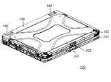
図1に示すように、情報処理装置100は、第1のユニット101と、第2のユニット102とを備える。第2のユニット102は、第1のユニット101に対して着脱可能である。第2のユニット102を第1のユニット101に装着した場合、情報処理装置100はノートブック型コンピュータとして利用することができる。また、第2のユニット102単体では、タブレット型コンピュータとして利用することができる。このように情報処理装置100は所謂デタッチャブル型コンピュータである。 As shown in FIG. 1, the
第2のユニット102は単体でタブレット型コンピュータとしての機能を有する。第2のユニット102は表示部121を備える。表示部121は、例えば液晶表示デバイスで構成され、第2の筐体120の一主面に取り付けられる。表示部121は有機ELデバイスのような他の表示デバイスで構成されてもよい。表示部121には、液晶表示デバイスに重畳してユーザのタッチ操作を受付可能なタッチパネルが設けられている。第2のユニット102は、コンピュータとしての機能を実現するため、中央演算処理装置(CPU)、揮発性記憶装置(RAM)、不揮発性記憶装置(ROM、SSD等)、バッテリ等を内蔵している。不揮発性記憶装置(ROM、SSD等)には、オペレーティングシステム(OS)、種々のアプリケーションプログラム、種々のデータ等が格納されている。中央演算処理装置(CPU)は、OS、アプリケーションプログラム、種々のデータを読み込んで演算処理を実行することにより、種々の機能を実現する。 The
第1のユニット101は、第1の筐体110と、ホルダ130と、ヒンジ部140とを備える。第1の筐体110は、例えば、マグネシウム合金などの金属や樹脂により形成される。第1のユニット101は、第2のユニットに対してユーザが入力操作を行うための入力部を備える。入力部として、第1の筐体110には、キーボード111、タッチパッド112及び操作ボタン113等が設けられている。 The
ホルダ130は第1のユニット101と電気的にまたは機械的に接続されている。ホルダ130は、第2のユニット102の一部を収容することで第2のユニット102を装着する。ホルダ130は、第2のユニット102を装着したときに、第1のユニット101と第2のユニット102とを電気的に接続する。 The
ヒンジ部140は、ホルダ130(すなわち、第2のユニット102)が第1のユニット101に対して回動できるようにホルダ130と第1のユニット101を連結する。 The
ホルダ130内には、第2のユニットのコネクタ(図示せず)と接続されるコネクタ(図示せず)が設けられている。また、ヒンジ部140内には、ホルダ130と第1のユニット101との間で各種信号や電力のやりとりするための配線が通されている。これらのコネクタや配線を介して、第2のユニット102と第1のユニット101との間で、種々の信号や電力の授受を行うことが可能となっている。 Inside the
図2は、第1のユニット101に対して第2のユニット102を閉じた状態での情報処理装置100の斜視図である。第1のユニット101の側面において、電源プラグ、外部機器、メモリカード等を接続するための接続端子が設けられている。各接続端子に対して、接続端子の未使用時に接続端子が露出しないようにするための端子カバーが設けられている。 FIG. 2 is a perspective view of the
第1のユニット101においても、第2のユニット102と同様に、メモリカード用の接続端子、イヤホン/マイクロホンの接続端子、HDMI(登録商標)端子、USB端子等が設けられており、それぞれに対して防水および防塵用の端子カバーが設けられている。 Similarly to the
また、本実施の形態の情報処理装置100は、第2のユニット102が第1のユニット101に対して閉じられた状態を保持するためのラッチ機構を備える。ラッチ機構は、第1のユニット101に設けられるラッチ201と、第2のユニット102に設けられる、ラッチ受け部202とを含む。ラッチ201は例えばマグネシウム等の金属材料で形成される。ラッチ201は、第1のユニット101において、情報処理装置100の前面側端部の中央に配置される。ラッチ受け部202は、第2のユニット102において、第2のユニット102を閉じたときに情報処理装置100の前面側となる端部の中央に設けられる。 The
[1−2.ラッチ機構]
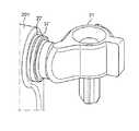
[1−2−1.ラッチ機構の外部構成]
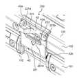
図3、4は、ラッチ201がロックされているときのラッチ機構の状態を示した図である。図3は情報処理装置100の正面から見たときの図であり、図4は情報処理装置100の斜め上から見たときの図である。[1-2. Latch mechanism]
[1-2-1. External configuration of latch mechanism]
3 and 4 are diagrams showing the state of the latch mechanism when the
第2の筐体120に設けられた凹部42内において、左右に突出部221、222が設けられている。各突出部221、222は係止穴221a、222aを有する。図3、4では、係止穴221a、222aは突出部221、222の上面に設けられているが、突出部221、222の反対側の面(下面)においても同様に設けられている。このように係止穴221a、222aを第2のユニット102の両面(表示部121が配置された面とその裏面)のいずれ側にも設けたことにより、第1のユニット101に対して、第2のユニット102を、その向きを問わず取り付けることを可能としている。第2の筐体120において、凹部42の上側と下側はそれぞれ壁状の係止部42a、42bが設けられている。
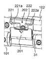
図5は、ラッチ201のロックが解除され、ラッチ201が解放された状態を示した図である。ラッチ201は、第1の筐体110に設けられた凹部40内において、回転軸を中心として回転可能に配置されている。ラッチ201は、回転軸から最も離れた側の端部において、回転の半径方向に向かって突き出た突起201a、201bが形成されている。また、ラッチ201の回転軸から最も離れた側の端部において、回転の半径方向に直交する方向に突出した突出部201d(係止部)が設けられている。 FIG. 5 is a diagram showing a state where the lock of the
ラッチ201は、ロック解除時において、下向きに最大限開いた(回転した)状態で、第1のユニット101の凹部40内に完全に収納されるようになっている。以下、ラッチ201がロック解除時に下向きに最大限開いた(回転した)状態で第1のユニット101の凹部40内に完全に収納されたときのラッチ201の回転位置(回転角度)を「第1の回転位置」または「収納位置」という。一方、ラッチ201がロックされたときのラッチ201の回転位置(回転角度)を「第2の回転位置」または「ロック位置」という。本実施形態では、第1の回転位置を0度とした場合、第2の回転位置は180度になる。 When the lock is released, the
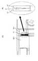
[1−2−2.ラッチ機構のロック動作]
図6A〜Cを参照してラッチ201のロック動作について説明する。図6Aは、第2のユニット102が第1のユニット101に対して閉じた状態において、ラッチ201が第1の回転位置にある状態、すなわち、ラッチ201のロックがかかっていない状態を示す。この状態から、ラッチ201をロックするためには、まず、ラッチ201を、先端の突起201a、201bが第2のユニット102の突出部221、222に当接するまで回転させる。ラッチ201の突起201a、201bが第2のユニット102の突出部221、222に最初に当接した状態で、さらにラッチ201を第2のユニット102側に押し込むと、突起201a、201bは、突出部221、222の表面を滑りながら、係止穴221a、222aに近づいて行く(図6B参照)。このとき、ラッチ201の回転軸は、付勢手段によって上方に向かって付勢されている(詳細は後述)。やがて、突起201a、201bが突出部221、222の係止穴221a、222aに到達すると、付勢手段により、突起201a、201bは係止穴221a、222a内に挿入される(図6C参照)。これにより、ラッチ201がロックされる。このときのラッチ201の回転位置は第2の回転位置(ロック位置)である。[1-2-2. Latch mechanism lock operation]
The lock operation of the
ロック状態では、ラッチ201の突起201a、201bが第2のユニット102に設けられた係止穴221a、222aに挿入されるため、ラッチ201の回転運動が規制される。この状態では(図6C参照)、第2のユニット102の下側の係止部42bは、ラッチ201の突出部201dよりも下側に位置している(換言すれば、係止部42bは、ラッチ201の突出部201dと回転軸の間に位置する)。この状態で第2のユニット102を開かせるためには、第2のユニット102の係止部42bがラッチ201の突出部201dの規制を受けないように突出部201dを移動させる必要がある。しかしながら、ロック状態では、ラッチ201の回転運動が規制されるため、ラッチ201の突出部201dを移動させることができない。このため、第2のユニット102を開くことができず、第2のユニット102が閉状態に保持される。 In the locked state, the
図7A〜Cを用いて、ラッチ201のロックの解除動作を説明する。図7Aはラッチ201のロック状態を示した図である。この状態で、付勢手段(後述)の付勢力に抗いながらラッチ201を下方に移動させ(図7B参照)、突起201a、201bを係止穴221a、222aから脱出させる。突起201a、201bを係止穴221a、222aから抜け出すと、ラッチ201は自重により下側に回転する(開く)(図7C参照)。これにより、ラッチ201の突出部201dが移動し、第2のユニット102の係止部42bの動きを妨げるものが無くなるため、第2のユニット102を開くことが可能となる。すなわち、ロックが解除される。以上のように、本実施形態のラッチ機構は、簡易な操作でラッチのロック及びロックの解除を実現することができる。 The unlocking operation of the
[1−2−3.ロック機構]
以上説明したラッチ201のロック動作及びロック解除動作を実現するためのラッチ機構の内部構成を説明する。[1-2-3. Lock mechanism]
The internal configuration of the latch mechanism for realizing the lock operation and the lock release operation of the
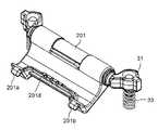
図8はラッチ機構の内部構成を示した図である。図9、10は、ラッチ201の周囲の構成要素を説明した図である。図11は、ラッチ201の回転運動を実現するための構成要素を説明するための断面図(水平断面図)である。図12は、ラッチ201の上下方向の移動を実現するための構成要素を説明するための断面図(垂直断面図)である。 FIG. 8 is a view showing the internal structure of the latch mechanism. 9 and 10 are diagrams illustrating components around the
図8に示すように、第1のユニット101において、ラッチ201の両側に、回転軸支持部31と、ばね33(付勢手段の一例)と、ばね支持部35とが配置される。回転軸支持部31は例えば樹脂で形成される。図9、11に示すように、シャフト21が、ラッチ201内を貫通し、ラッチ201の両端で回転軸支持部31により支持される。これにより、ラッチ201は、シャフト21を回転軸として回転することができる。なお、ラッチ201におけるシャフト21のための貫通口の口径は、シャフト21の回転軸の摩擦が小さくなるように、シャフト21の直径よりも大きな値に設定されている。このため、ラッチ201は、ロックされていない状態では、自重によって下側に開く(回転する)。 As shown in FIG. 8, in the
図9に示すように、回転軸支持部31は、軸保持部31aとばね取り付け部31bとを有する。軸保持部31aはシャフト21を保持する。ばね取り付け部31bには、図10、12に示すように、回転軸支持部31を、所定方向(ばね33から回転軸支持部31に向かう方向)に付勢するためのばね33が取り付けられる。ばね33は、第1の筐体110に形成されたばね支持部35により保持される。 As shown in FIG. 9, the rotary
後述するように回転軸支持部31は、所定方向またはその逆方向に移動可能となっている。以下、回転軸支持部31の位置に関し、第2のユニット102を閉じた状態で回転軸支持部31が第2のユニット102のラッチ受け部202から最も離れる位置を「第1の位置」という。一方、ラッチ201がロックされた状態で回転軸支持部31が取り得る位置を「第2の位置」という。すなわち、ラッチ201は、少なくとも第1の回転位置から第2の回転位置まで回転可能であり、回転軸支持部31は少なくとも第1の位置から第2の位置まで移動可能である。 As will be described later, the rotary
図13は、第1のユニット101における、ラッチ201を収納する凹部40を説明した図である。凹部40の左右にある壁部40b、40cには上下方向に形成された溝41が設けられている。図14は、溝41に挿入された回転軸支持部31と、それに接続するシャフト21を説明した図である。回転軸支持部31は、溝41内を、ラッチ201を押し下げる力又はばね33の付勢による力にしたがい上下に移動することができる。なお、ばね33の付勢力は、ラッチ201のロック状態においてラッチ201の突起201a、201bが第2のユニット102の係止穴221a、222aに挿入できるように、回転軸支持部31を第2の位置まで移動させることができる程度の力である必要がある。 FIG. 13 is a diagram illustrating the
以上のようにラッチ機構を構成することにより、図15に示すように、ラッチ201を、回転軸(シャフト21)を中心として回転させることが可能になるとともに、回転軸を上下に移動させることが可能となる。このようなラッチ201の回転と上下動の動きにより、図6、7で説明したような簡易な操作でラッチ201のロック動作及びロック解除動作を実現することが可能となる。ラッチ機構として本体外部に設ける部品はラッチ201のみでよく、構成が簡易であり大きなスペースを必要としない。このため、本実施の形態で示すラッチ機構は薄型の装置にも搭載することができる。 By configuring the latch mechanism as described above, as shown in FIG. 15, the
[1−2−4.回転抑制構造]
図16〜図19を用いて、ラッチ201の回転抑制構造を説明する。前述のように、ラッチ201は、ロック状態にないときは、シャフト21を回転軸として自由に回転できるようになっている。このため、情報処理装置100を、移動する車両内のような振動の多い環境で使用した場合、ラッチ201が振動してノイズが発生する。これを防止するため、本実施の形態では、ラッチ201のロック解除時において、ラッチ201が振動しないよう工夫がなされている。[1-2-4. Rotation suppression structure]
The rotation suppressing structure of the
図16は、ラッチ201の回転を抑制するための構成を説明するための図である。ラッチ201の回転を抑制するために、ラッチ201において、回転軸21と同軸上に配置され、リング形状を有するリング状部27が設けられている。また、回転軸支持部31の軸保持部31aにおいて、回転軸21と同軸上に配置され、リング形状を有するリング状部37が設けられている。 FIG. 16 is a diagram for explaining a configuration for suppressing the rotation of the
図17は、リング状部27、37の構造上の特徴を説明した図である。図17(A)は、リング状部27、37の上面図であり、図17(B)は、リング状部27、37の側面図である。例えば、図17(B)に示すように、リング状部27、37は、高さ方向において、高さが連続的に変化するように(すなわち、勾配を有するように)形成される。具体的には、リング状部27、37は、位置Bにおいて最も高さが高くなり、リングの中心を基準として位置Bと対称な位置Aにおいて最も高さが低くなるように形成される。 FIG. 17 is a diagram illustrating the structural features of the ring-shaped
図18は、ラッチ201が第2の回転位置(ロック位置)にあるときの、ラッチ201及び回転軸支持部31におけるリング状部27、37の状態を説明した図である。図19は、ラッチ201が第1の回転位置(収納位置)にあるときの、2つのリング状部27、37の状態を説明した図である。これらの図に示すように、ラッチのリング状部27と回転軸支持部31のリング状部37の高さは、ラッチ201が第2の回転位置(ロック位置)から第1の回転位置(収納位置)に向かって回転するにつれて、リング状部27とリング状部37の当接面積が増大するように設定されている。 FIG. 18 is a diagram illustrating the states of the ring-shaped
具体的には、図18に示すように、ラッチ201が第2の回転位置(ロック位置)にあるときには、リング状部27の高さが高い部分と、回転軸支持部31のリング状部37の高さが低い部分とが対向し、リング状部27の高さが低い部分と、リング状部37の高さが高い部分とが対向するように、それぞれのリング状部27、37が形成される。このとき、図18(B)に示すように、ラッチ201のリング状部27と回転軸支持部31のリング状部37との間には隙間が形成され、このため、ラッチ201はリング状部27、37によって阻害されることなく回転することができる。 Specifically, as shown in FIG. 18, when the
以上のようにリング状部27、37を形成することで、ラッチ201を第1の回転位置(収納位置)に回転させたときには、リング状部27の高さが高い部分と、回転軸支持部31のリング状部37の高さが高い部分とが対向する(図19参照)。このとき、図19(B)に示すように、ラッチ201のリング状部27の高さが高い部分と回転軸支持部31のリング状部37の高さが高い部分とが当接(干渉)する。この当接(干渉)による摩擦のため、ラッチ201の回転が抑制され、ラッチ201が第1の回転位置(収納位置)に固定される。 By forming the ring-shaped
以上のようなリング状部27、37により、ラッチのロックをかける時には、ラッチ201を自由に回転させることができる。一方、ラッチのロックを解除する時には、ラッチ201を収納位置に固定することができ、ラッチの振動を抑制できる。すなわち、振動防止のための専用のクッションやばねを用いずに、ラッチ201の振動を低減でき、振動によるノイズの発生を抑制することができるため、構成を簡易にでき小型化を実現できる。 When the latch is locked by the ring-shaped
なお、リング状部27、37の形状は図17に示す構造に限定されるものではない。リング状部27、37は、高さの比較的に高い部分と、高さの比較的に低い部分とを有する構造であればよい。そして、ラッチ201が第2の回転位置(ロック位置)及びその近傍にあるときには、ラッチ201のリング状部27の高さが比較的高い部分(または低い部分)と、回転軸支持部31のリング状部37の高さが比較的低い部分(または高い部分)が対向し、ラッチ201が第1の回転位置(収納位置)にあるときには、互いのリング状部27、37の高さが比較的高い部分どうしが対向して当接するように、リング状部27、37の形状(高さ)を調整すればよい。 The shape of the ring-shaped
また、上述したリング状の回転抑制構造は、ラッチ機構のみならず、他の回転機構に対しても適用することができる。すなわち、図20に示すように、部材Aが部材Bに対して回転可能に連結されている場合に、回転軸321と同軸上に配置され、かつ、高さ方向において勾配を有するように変化するリング状部327、337をそれぞれ部材Aと部材Bに形成すればよい。この場合、回転を抑制したい回転位置において、図20(B)に示すようにリング状部327、337の比較的高さが高い部分が互いに対向するように、それとリング状部327、337の高さを調整すればよい。 Further, the ring-shaped rotation suppressing structure described above can be applied not only to the latch mechanism but also to other rotation mechanisms. That is, as shown in FIG. 20, when the member A is rotatably connected to the member B, it is arranged coaxially with the
[1−3.効果、等]
以上のように本実施形態の情報処理装置100は、第1のユニット101と、第1のユニット101に対して開閉可能な第2のユニット102とを備えた電子機器であって、第2のユニット102を第1のユニット101に対して閉状態に固定するラッチ機構(202、201)を備える。ラッチ機構は、第1のユニット101に設けられ、突起201a、201b(第1の係合部の一例)が先端に設けられ、シャフト21(回転軸の一例)を中心として第1の回転位置から第2の回転位置まで回転可能なラッチ201と、第1のユニット101に設けられ、シャフト21を回転可能に支持するとともに、第1の位置と第2の位置の間を移動可能な回転軸支持部31と、第1のユニット101に設けられ、回転軸支持部31を第1の位置から第2の位置に向かう方向に付勢するばね33(付勢部の一例)と、第2のユニット102に設けられ、突起201a、201bと係合可能な係止穴221a、222a(第2の係合部の一例)と、を備える。突起201a、201bと係止穴221a、222aは、第2のユニット102が第1のユニット101に対して閉状態にあり、回転軸支持部31が第2の位置にあり、且つラッチ201が第2の回転位置にあるときに係合する。[1-3. Effect, etc.]
As described above, the
以上のようなラッチ機構により、回転と上下移動の簡易な操作によりラッチのロック/解除動作が可能となる。また、本体外部に設ける部品点数も低減できるため、ラッチ機構を薄型の電子機器に対しても適用することができる。 The latch mechanism as described above enables the lock/unlock operation of the latch by a simple operation of rotation and vertical movement. Further, since the number of parts provided outside the main body can be reduced, the latch mechanism can be applied to thin electronic devices.
情報処理装置100において、ラッチ201は突出部201d(第1の係止部の一例)を備え、第2のユニット102(第2の筐体120)は係止部42b(第2の係止部の一例)を備えてもよい。係止部42bは、第2のユニット102が第1のユニット101に対して閉状態にあり、且つラッチ201が第2の回転位置にあるときは(すなわち、ロック状態にあるとき)、突出部201dと回転軸(シャフト21)の間に位置する。ロック状態におけるこのような突出部201dと係止部42bの位置関係により、ラッチ201がロックされたときに、第1のユニット101に対して第2のユニット102を開くことが防止される。 In the
また、本実施の形態の情報処理装置100に搭載される、別の態様のラッチ機構は、回転軸(シャフト21)を中心として収納位置とロック位置の間で回転可能であり、ロック位置で、第1のユニット101と第2のユニット102とを閉状態で固定するラッチ201と、回転軸を回転可能に支持する回転軸支持部31と、を備える。ラッチ201は、回転軸と同軸上に配置され、リング形状を有する第1のリング部27を有する。回転軸支持部31は、回転軸(シャフト21)と同軸上に配置され、リング形状を有する第2のリング部37を有する。第1のリング部と第2のリング部の高さは、ラッチがロック位置から収納位置に向かって回転するにつれて、第1のリング部27と第2のリング部37の当接面積が増大するように設定される。 Further, the latch mechanism of another aspect mounted on the
以上のようなリング状部により、ロック解除時に、ラッチ201を固定することができ、ラッチの振動を抑制できる。すなわち、振動防止のための専用のクッションやばねを用いずに、ラッチ201の振動を低減でき、振動によるノイズの発生を抑制することができるため、構成を簡易にでき小型化を実現できる。 With the ring-shaped portion as described above, the
(他の実施の形態)
以上のように、本出願において開示する技術の例示として、実施の形態1を説明した。しかしながら、本開示における技術は、これに限定されず、適宜、変更、置き換え、付加、省略などを行った実施の形態にも適用可能である。また、上記実施の形態1で説明した各構成要素を組み合わせて、新たな実施の形態とすることも可能である。そこで、以下、他の実施の形態を例示する。(Other embodiments)
As described above, the first embodiment has been described as an example of the technique disclosed in the present application. However, the technique in the present disclosure is not limited to this, and is also applicable to the embodiment in which changes, replacements, additions, omissions, etc. are appropriately made. Further, it is also possible to combine the constituent elements described in the first embodiment to form a new embodiment. Therefore, other embodiments will be exemplified below.
実施の形態1では、入力部を有する第1のユニット101側にラッチ201を設けたが、表示部を有する第2のユニット102側にラッチ201を設けてもよい。 Although the
実施の形態1では、回転軸支持部31を付勢する手段としてコイル状のばねを用いたが、付勢手段はこれに限定されない。付勢手段として、例えば、トーションばね、板バネのようなばねや、ばね以外の弾性部材を用いてもよい。 Although the coil-shaped spring is used as the means for urging the rotary
実施の形態1で示した突起、突出部、係止部、係止穴等の形状は一例であり、上述したものに限定されない。同様の機能を実現するものであれば、突起、突出部等の形状は他の形状であってもよい。 The shapes of the protrusion, the protruding portion, the locking portion, the locking hole, and the like shown in the first embodiment are examples, and the shapes are not limited to the above. The shapes of the protrusions and the protrusions may be other shapes as long as they achieve the same function.
実施の形態1では、電子機器の一例として、所謂デタッチャブル型コンピュータを説明したが、本開示の思想は他の種類の電子機器にも適用することができる。例えば、ノート型パソコン、ワードプロセッサ、電子辞書のような開閉可能なユニットを備えた電子機器に対して適用できる。 In the first embodiment, the so-called detachable computer has been described as an example of the electronic device, but the idea of the present disclosure can be applied to other types of electronic devices. For example, it can be applied to an electronic device including a unit such as a notebook computer, a word processor, and an electronic dictionary that can be opened and closed.
以上のように、本開示における技術の例示として、実施の形態を説明した。そのために、添付図面および詳細な説明を提供した。 As described above, the embodiments have been described as examples of the technology according to the present disclosure. To that end, the accompanying drawings and detailed description are provided.
したがって、添付図面および詳細な説明に記載された構成要素の中には、課題解決のために必須な構成要素だけでなく、上記技術を例示するために、課題解決のためには必須でない構成要素も含まれ得る。そのため、それらの必須ではない構成要素が添付図面や詳細な説明に記載されていることをもって、直ちに、それらの必須ではない構成要素が必須であるとの認定をするべきではない。 Therefore, among the components described in the accompanying drawings and the detailed description, not only the components essential for solving the problem but also the components not essential for solving the problem in order to exemplify the above technology Can also be included. Therefore, it should not be immediately recognized that these non-essential components are essential, even if those non-essential components are described in the accompanying drawings or the detailed description.
また、上述の実施の形態は、本開示における技術を例示するためのものであるから、特許請求の範囲またはその均等の範囲において種々の変更、置き換え、付加、省略などを行うことができる。 Further, since the above-described embodiment is for exemplifying the technique in the present disclosure, various changes, replacements, additions, omissions, etc. can be made within the scope of the claims or the scope of equivalents thereof.
本開示は、ノート型パソコン、ワードプロセッサ、電子辞書のような開閉可能なユニットを備えた電子機器に有用である。 The present disclosure is useful for electronic devices that include a unit that can be opened and closed, such as a notebook computer, a word processor, and an electronic dictionary.
21 シャフト
27 ラッチのリング状部
31 回転軸支持部
33 ばね
35 ばね支持部
37 回転軸支持部のリング状部
40 第1の筐体の凹部
42 第2の筐体の凹部
42a,42b 第2の筐体における係止部
100 情報処理装置
101 第1のユニット
102 第2のユニット(タブレット端末)
110 第1の筐体
120 第2の筐体
130 ホルダ
140 ヒンジ部
201 ラッチ
201a,201b 突起
201d ラッチの突出部(係止部)
202 ラッチ受け部
221,222 ラッチ受け部の突出部
221a,222a 係止穴21
110
202
Claims (6)
Translated fromJapanese前記第2のユニットを前記第1のユニットに対して閉状態に固定するラッチ機構を備え、
前記ラッチ機構は、
前記第1のユニットに設けられ、第1の係合部が先端に設けられ、回転軸を中心として第1の回転位置から第2の回転位置まで回転可能なラッチと、
前記第1のユニットに設けられ、前記回転軸をその両側から所定方向へ付勢する付勢部と、
前記第2のユニットに設けられ、前記第1の係合部と係合可能な第2の係合部と、を備え、
前記第1及び第2の係合部は、前記第2のユニットが前記第1のユニットに対して閉状態にあり、前記回転軸が前記付勢部により前記所定方向へ付勢され、且つ前記ラッチが前記第2の回転位置にあるときに係合する、
電子機器。An electronic device comprising a first unit and a second unit that can be opened and closed with respect to the first unit,
A latch mechanism for fixing the second unit in a closed state with respect to the first unit;
The latch mechanism is
A latch provided on the first unit, having a first engaging portion provided at a tip thereof, and rotatable about a rotation axis from a first rotation position to a second rotation position;
A biasing portion that is provided in the first unit and that biases the rotary shaft from both sides thereof in a predetermined direction;
A second engaging portion that is provided in the second unit and is engageable with the first engaging portion,
The first and second engaging portions are such that the second unit is in a closed state with respect to the first unit, therotating shaft is biased in the predetermined direction by the biasing portion, and Engages when the latch is in the second rotational position,
Electronics.
前記第2のユニットは第2の係止部を備え、
前記第2の係止部は、前記第2のユニットが前記第1のユニットに対して閉状態にあり、且つ前記ラッチが前記第2の回転位置にあるときは、前記第1の係止部と前記回転軸の間に位置する、
請求項1に記載の電子機器。The latch includes a first locking portion,
The second unit includes a second locking portion,
The second locking portion is the first locking portion when the second unit is closed with respect to the first unit and the latch is in the second rotation position. And located between the rotation axis,
The electronic device according to claim 1.
前記第1のユニットに設けられ、第1の係合部が先端に設けられ、回転軸を中心として第1の回転位置から第2の回転位置まで回転可能なラッチと、
前記第1のユニットに設けられ、前記回転軸をその両側から所定方向へ付勢する付勢部と、
前記第2のユニットに設けられ、前記第1の係合部と係合可能な第2の係合部と、を備え、
前記第1の係合部と前記ラッチの第2の係合部は、前記第2のユニットが前記第1のユニットに対して閉状態にあり、前記回転軸が前記付勢部により前記所定方向へ付勢され、且つ前記ラッチが前記第2の回転位置にあるときに係合する、
ラッチ機構。In a device including a first unit and a second unit that can be opened and closed with respect to the first unit, a latch mechanism that fixes the second unit in a closed state with respect to the first unit. There
A latch provided on the first unit, having a first engaging portion provided at a tip thereof, and rotatable about a rotation axis from a first rotation position to a second rotation position;
A biasing portion that is provided in the first unit and that biases the rotary shaft from both sides thereof in a predetermined direction;
A second engaging portion that is provided in the second unit and is engageable with the first engaging portion,
The first engaging portion and the second engaging portion of the latch are such that the second unit is in a closed state with respect to the first unit, and therotating shaft is in the predetermined direction by the urging portion. biased f engages when and said latch is in said second rotational position,
Latch mechanism.
Applications Claiming Priority (3)
| Application Number | Priority Date | Filing Date | Title |
|---|---|---|---|
| JP2015218845 | 2015-11-06 | ||
| JP2015218845 | 2015-11-06 | ||
| PCT/JP2016/003409WO2017077667A1 (en) | 2015-11-06 | 2016-07-21 | Electronic device and latch mechanism |
Publications (2)
| Publication Number | Publication Date |
|---|---|
| JPWO2017077667A1 JPWO2017077667A1 (en) | 2018-08-23 |
| JP6735454B2true JP6735454B2 (en) | 2020-08-05 |
Family
ID=58663193
Family Applications (1)
| Application Number | Title | Priority Date | Filing Date |
|---|---|---|---|
| JP2017548614AActiveJP6735454B2 (en) | 2015-11-06 | 2016-07-21 | Electronic equipment and latch mechanism |
Country Status (4)
| Country | Link |
|---|---|
| US (1) | US10444801B2 (en) |
| JP (1) | JP6735454B2 (en) |
| CN (3) | CN106681432B (en) |
| WO (1) | WO2017077667A1 (en) |
Families Citing this family (7)
| Publication number | Priority date | Publication date | Assignee | Title |
|---|---|---|---|---|
| JP6735454B2 (en)* | 2015-11-06 | 2020-08-05 | パナソニックIpマネジメント株式会社 | Electronic equipment and latch mechanism |
| CN113741627B (en)* | 2018-11-30 | 2025-04-22 | 神讯电脑(昆山)有限公司 | Buckle structure |
| JP1639741S (en)* | 2018-12-20 | 2020-02-17 | ||
| USD981408S1 (en) | 2018-12-20 | 2023-03-21 | Panasonic Intellectual Property Management Co., Ltd. | Portable computer |
| JP2020164204A (en)* | 2019-03-29 | 2020-10-08 | 株式会社良品計画 | container |
| WO2022181002A1 (en)* | 2021-02-26 | 2022-09-01 | パナソニックIpマネジメント株式会社 | Electronic device |
| US20220357768A1 (en)* | 2021-05-05 | 2022-11-10 | Michael Feroli | System for packaging a portable computer |
Family Cites Families (34)
| Publication number | Priority date | Publication date | Assignee | Title |
|---|---|---|---|---|
| JPH0736569A (en) | 1993-07-22 | 1995-02-07 | Ricoh Co Ltd | Electronics |
| US6125040A (en)* | 1998-02-27 | 2000-09-26 | Fujitsu Limited | Information processing apparatus and hook mechanism applicable to the apparatus |
| JP4212708B2 (en)* | 1998-03-16 | 2009-01-21 | 富士通株式会社 | Information processing apparatus and electronic device |
| CN2488099Y (en)* | 2001-03-26 | 2002-04-24 | 神基科技股份有限公司 | Fastening device |
| JP2004005210A (en)* | 2002-05-31 | 2004-01-08 | Toshiba Corp | Electronic device |
| CN2599633Y (en)* | 2002-12-19 | 2004-01-14 | 仁宝电脑工业股份有限公司 | Easy-to-open fastening device |
| JP2004234194A (en)* | 2003-01-29 | 2004-08-19 | Toshiba Corp | Electronics |
| JP2004326440A (en)* | 2003-04-24 | 2004-11-18 | Sharp Corp | Information processing device |
| KR100745813B1 (en)* | 2003-08-11 | 2007-08-02 | 엘지전자 주식회사 | Bidirectional latch assembly and electronic device using same |
| TWI225980B (en)* | 2003-10-24 | 2005-01-01 | Asustek Comp Inc | Apparatus with hidden latch |
| TWI260961B (en)* | 2004-02-03 | 2006-08-21 | Wistron Corp | Machinery system including a rotatable hook |
| US7637540B2 (en)* | 2004-02-05 | 2009-12-29 | Asustek Computer Inc. | Latch structure |
| JP2005267590A (en)* | 2004-03-18 | 2005-09-29 | Makoto Kida | Notebook computer, and latch storage mechanism |
| TWM270634U (en)* | 2004-08-19 | 2005-07-11 | Compal Electronics Inc | Engagement module of portable computer |
| CN2763868Y (en)* | 2004-12-11 | 2006-03-08 | 鸿富锦精密工业(深圳)有限公司 | Lock for cover of notebook computer |
| TWI257040B (en)* | 2004-12-27 | 2006-06-21 | Tatung Co | Common lock structure for dual portable computer |
| WO2006112022A1 (en)* | 2005-04-15 | 2006-10-26 | Fujitsu Limited | Lock device for foldable case, and electronic device provided with same |
| JP2007059662A (en)* | 2005-08-25 | 2007-03-08 | Casio Comput Co Ltd | Opening / closing lid locking device and waterproof device |
| CN2909348Y (en)* | 2006-03-15 | 2007-06-06 | 鸿富锦精密工业(深圳)有限公司 | Buckle device |
| CN2916734Y (en)* | 2006-04-20 | 2007-06-27 | 英业达股份有限公司 | Concealed Fastening Components |
| CN100592845C (en)* | 2006-12-22 | 2010-02-24 | 鸿富锦精密工业(深圳)有限公司 | Snapping device |
| CN101211195B (en)* | 2006-12-25 | 2011-01-12 | 华硕电脑股份有限公司 | foldable electronic device |
| US7438333B2 (en)* | 2007-01-30 | 2008-10-21 | Inventec Corporation | Magnetic latch assembly |
| KR20080076380A (en)* | 2007-02-15 | 2008-08-20 | 삼성전자주식회사 | Information processing device |
| TW200847891A (en)* | 2007-05-25 | 2008-12-01 | Mitac Technology Corp | Movable engaging door structure |
| CN101662906B (en)* | 2008-08-26 | 2011-08-31 | 鸿富锦精密工业(深圳)有限公司 | Electronic device |
| CN101660555A (en)* | 2008-08-26 | 2010-03-03 | 鸿富锦精密工业(深圳)有限公司 | Fastening device and electronic equipment using same |
| CN101872913B (en)* | 2009-04-21 | 2012-10-17 | 深圳富泰宏精密工业有限公司 | Connection structure and electronic device applying same |
| CN102316684B (en)* | 2010-06-30 | 2014-12-24 | 深圳市齐创美科技有限公司 | Portable electronic device shell |
| TWI387425B (en)* | 2010-10-29 | 2013-02-21 | Wistron Corp | Latch mechanism and portable computer |
| US8576562B2 (en)* | 2011-02-16 | 2013-11-05 | Dell Products L.P. | Latching system for convertible information handling system |
| TWI507845B (en)* | 2012-09-28 | 2015-11-11 | Mitac Technology Corp | A locker structure of an electronic device |
| JP6735454B2 (en)* | 2015-11-06 | 2020-08-05 | パナソニックIpマネジメント株式会社 | Electronic equipment and latch mechanism |
| TWI732340B (en)* | 2019-11-13 | 2021-07-01 | 和碩聯合科技股份有限公司 | Fastening structure |
- 2016
- 2016-07-21JPJP2017548614Apatent/JP6735454B2/enactiveActive
- 2016-07-21WOPCT/JP2016/003409patent/WO2017077667A1/ennot_activeCeased
- 2016-08-25CNCN201610726973.2Apatent/CN106681432B/enactiveActive
- 2016-08-25CNCN202110833826.6Apatent/CN113550668B/enactiveActive
- 2016-08-25CNCN201620946711.2Upatent/CN206193592U/enactiveActive
- 2018
- 2018-04-19USUS15/957,795patent/US10444801B2/enactiveActive
Also Published As
| Publication number | Publication date |
|---|---|
| CN206193592U (en) | 2017-05-24 |
| CN113550668A (en) | 2021-10-26 |
| US10444801B2 (en) | 2019-10-15 |
| CN106681432A (en) | 2017-05-17 |
| US20180239398A1 (en) | 2018-08-23 |
| CN106681432B (en) | 2021-08-10 |
| JPWO2017077667A1 (en) | 2018-08-23 |
| CN113550668B (en) | 2023-03-24 |
| WO2017077667A1 (en) | 2017-05-11 |
Similar Documents
| Publication | Publication Date | Title |
|---|---|---|
| JP6735454B2 (en) | Electronic equipment and latch mechanism | |
| US11907025B2 (en) | Electronic device and latch mechanism | |
| CN110325944A (en) | External locking device | |
| US9575513B2 (en) | Electronic device and apparatus | |
| JP7241307B2 (en) | Electronics | |
| JP3665235B2 (en) | Locking device for computer expansion unit | |
| JP2013239051A (en) | Information processing apparatus | |
| TW202119160A (en) | Dock for a portable electronic device | |
| JP2021051771A (en) | Electronic apparatus | |
| JP6693510B2 (en) | Placement device | |
| CN114776140A (en) | Lock set | |
| JP6631625B2 (en) | Mounting device | |
| CN103838306B (en) | Electronic device | |
| TWI457744B (en) | Computer peripheral device capable of fixing on a casing of a portable computer | |
| JP2011096118A (en) | Electronic equipment | |
| JP2013231839A (en) | Electronic apparatus | |
| JP5703897B2 (en) | Memory card holding mechanism and electronic device having the same | |
| JP7557164B1 (en) | Information processing device | |
| JP2010225183A (en) | Electronics | |
| JP2012164382A (en) | Medium drive device | |
| JP2014013597A (en) | Electronic apparatus |
Legal Events
| Date | Code | Title | Description |
|---|---|---|---|
| A521 | Request for written amendment filed | Free format text:JAPANESE INTERMEDIATE CODE: A523 Effective date:20180417 | |
| RD01 | Notification of change of attorney | Free format text:JAPANESE INTERMEDIATE CODE: A7421 Effective date:20190123 | |
| A621 | Written request for application examination | Free format text:JAPANESE INTERMEDIATE CODE: A621 Effective date:20190412 | |
| A131 | Notification of reasons for refusal | Free format text:JAPANESE INTERMEDIATE CODE: A131 Effective date:20200225 | |
| A521 | Request for written amendment filed | Free format text:JAPANESE INTERMEDIATE CODE: A523 Effective date:20200420 | |
| TRDD | Decision of grant or rejection written | ||
| A01 | Written decision to grant a patent or to grant a registration (utility model) | Free format text:JAPANESE INTERMEDIATE CODE: A01 Effective date:20200526 | |
| A61 | First payment of annual fees (during grant procedure) | Free format text:JAPANESE INTERMEDIATE CODE: A61 Effective date:20200608 | |
| R151 | Written notification of patent or utility model registration | Ref document number:6735454 Country of ref document:JP Free format text:JAPANESE INTERMEDIATE CODE: R151 |