JP6735161B2 - Blood collection device and method of operating blood collection device - Google Patents
Blood collection device and method of operating blood collection deviceDownload PDFInfo
- Publication number
- JP6735161B2 JP6735161B2JP2016122241AJP2016122241AJP6735161B2JP 6735161 B2JP6735161 B2JP 6735161B2JP 2016122241 AJP2016122241 AJP 2016122241AJP 2016122241 AJP2016122241 AJP 2016122241AJP 6735161 B2JP6735161 B2JP 6735161B2
- Authority
- JP
- Japan
- Prior art keywords
- blood collection
- blood
- finger
- collection device
- holder
- Prior art date
- Legal status (The legal status is an assumption and is not a legal conclusion. Google has not performed a legal analysis and makes no representation as to the accuracy of the status listed.)
- Active
Links
Images


Classifications
- A—HUMAN NECESSITIES
- A61—MEDICAL OR VETERINARY SCIENCE; HYGIENE
- A61B—DIAGNOSIS; SURGERY; IDENTIFICATION
- A61B5/00—Measuring for diagnostic purposes; Identification of persons
- A61B5/15—Devices for taking samples of blood
Landscapes
- Health & Medical Sciences (AREA)
- Life Sciences & Earth Sciences (AREA)
- Heart & Thoracic Surgery (AREA)
- Medical Informatics (AREA)
- Biophysics (AREA)
- Pathology (AREA)
- Engineering & Computer Science (AREA)
- Biomedical Technology (AREA)
- Hematology (AREA)
- Physics & Mathematics (AREA)
- Molecular Biology (AREA)
- Surgery (AREA)
- Animal Behavior & Ethology (AREA)
- General Health & Medical Sciences (AREA)
- Public Health (AREA)
- Veterinary Medicine (AREA)
- Measurement Of The Respiration, Hearing Ability, Form, And Blood Characteristics Of Living Organisms (AREA)
Description
Translated fromJapanese本発明は、被験者の指から採血を実施する装置に関する。 The present invention relates to a device for collecting blood from a finger of a subject.
健康的な生活を送るためには、定期的に健康診断を受診することが重要である。健康診断にて一般的によく実施されている検査の一つが、被験者から採血し血液の成分を分析することで全身の組織や臓器の状態を診断する血液検査である。一般的な血液検査は医療機関で実施することが多いが、血糖値のように測定項目を限定した自己検査として、家庭内で実施することも多い。 In order to lead a healthy life, it is important to undergo regular medical examinations. One of the tests commonly performed in health checkups is a blood test for diagnosing the state of tissues and organs of the whole body by collecting blood from a subject and analyzing blood components. Although a general blood test is often carried out at a medical institution, it is often carried out at home as a self-test in which measurement items such as blood glucose level are limited.
血糖値測定などの自己検査のための採血として実施されることが多い採血方法が、毛細血管採血である。毛細管採血は、被験者の指に専用の皮膚穿刺器具を押し当てることで指の毛細血管を穿刺し、流出した血液を採血する方法である。毛細管採血は、静脈血採血よりも簡便であり、自己検査であれば医療従事者に限らず実施することが可能である。しかし、確保することのできる血量が少ないため、数十μLの採血量を確保するためには、採血の際に指を圧迫し絞るなどの煩雑な作業を必要とする。 Capillary blood sampling is a blood sampling method that is often performed as blood sampling for self-test such as blood glucose measurement. Capillary blood sampling is a method in which a dedicated skin puncturing device is pressed against the finger of a subject to puncture the capillary blood vessels of the finger and collect the outflowing blood. Capillary blood sampling is simpler than venous blood sampling, and can be performed by self-examination not limited to medical staff. However, since the blood volume that can be secured is small, in order to secure a blood collection volume of several tens μL, a complicated work such as pressing and squeezing a finger during blood collection is required.
特許文献1には、指からの採血を簡易な操作で実現する穿刺装置が開示されている。この穿刺装置は、穿刺要素が出入りする開口部に指先を収容するための蓋を有する圧迫手段でもって指先を押しつけ、指の根元側から指先の方向に血液を送るための搾液機構を有することを特徴とし、指先の穿刺後に指の根元から指先の方向に搾液機構を動かすことで血液を絞り出す。
また、特許文献2には、検査に必要な量の血液を採取する採血装置が開示されている。この採血装置は、指先の穿刺後に指先から遠い締めつけ部材から穿刺部位に近い締付け部材へと順番に圧迫部位を移すことで、血液を指先に押し出し、穿刺部位から血液を絞り出す。 Further,
上記特許文献1に記載されている穿刺装置及び上記特許文献2に記載されている採血装置は、被験者が煩雑な作業をせずに指先からの毛細血管採血を実施可能なことが利点である。しかし、被験者毎に指の長さ、太さ、血圧などの値には個人差があるため、どのような被験者に対しても安定した採血を実現するためには、これらの値の個人差に対するロバスト性を有した採血装置が求められる。 The puncture device described in
本発明は、上述した従来技術の課題に鑑みて達成されたものであり、その目的は、どのような被験者でも安全かつ簡便に指先からの採血を実現することができる採血手段及び採血装置を提供することにある。 The present invention has been achieved in view of the above-described problems of the prior art, and an object thereof is to provide a blood sampling means and a blood sampling device that allow any subject to safely and easily realize blood sampling from a fingertip. To do.
上記の目的を達成するための本発明の構成は以下の通りである。 The structure of the present invention for achieving the above object is as follows.
すなわち、生体の穿刺対象部位を穿刺する穿孔針を有する穿孔針ホルダ、前記穿刺対象部位の穿刺痕より流出する体液を捕集する容器を有する容器ホルダ、前記穿刺痕を封止するシールを有するシールホルダ、及び前記穿孔器ホルダ、前記容器ホルダ並びに前記シールホルダを移動可能に保持するカートリッジケースを有するカートリッジと、前記穿刺対象部位と前記カートリッジの水平方向の相対位置を変化させ、かつ、前記穿刺対象部位と前記穿孔器、前記容器及び前記シールの垂直方向の相対位置を変化させる駆動機構と、前記穿刺対象部位の一部を固定するための第一の固定機構と、前記穿刺対象部位の別の一部を圧迫するための圧迫機構を備えると共に位置が可変である第二の固定機構を備えていることを特徴としている。 That is, a perforation needle holder having a perforation needle for puncturing a puncture target site of a living body, a container holder having a container for collecting body fluid flowing out from the puncture trace of the puncture target site, and a seal having a seal for sealing the puncture trace A cartridge having a holder and a cartridge case that movably holds the punch holder, the container holder, and the seal holder, the relative position in the horizontal direction of the puncture target site and the cartridge, and the puncture target A drive mechanism for changing the relative position of the part and the perforator, the container and the seal in the vertical direction, a first fixing mechanism for fixing a part of the part to be punctured, and another part of the part to be punctured. It is characterized in that a compression mechanism for compressing a part is provided and a second fixing mechanism whose position is variable is provided.
また本発明の他の構成は以下の通りである。 Another configuration of the present invention is as follows.
すなわち、穿刺針、容器およびシールを移動可能に保持するカートリッジを装置に取り付ける工程と、穿刺対象部位を圧迫する工程と、前記カートリッジに保持された穿刺針を穿刺対象部位に押しつける工程と、前記カートリッジを水平方向に移動させる工程と、前記カートリッジに保持された容器を穿刺痕に押しつけ、当該穿刺痕より流出する体液を収集する工程と、前記カートリッジをさらに水平方向に移動させる工程と、穿刺対象部位に対する圧迫を開放する工程と、前記カートリッジに保持されたシールを前記穿刺痕に押しつけ、当該穿刺痕をシールで封止する工程と、を有している。 That is, a step of attaching a cartridge that movably holds a puncture needle, a container and a seal to a device, a step of pressing a puncture target site, a step of pressing the puncture needle held in the cartridge to the puncture target site, and the cartridge In the horizontal direction, pressing the container held in the cartridge against the puncture mark and collecting body fluid flowing out from the puncture mark, further moving the cartridge in the horizontal direction, and a puncture target site The step of releasing the pressure on the puncture mark, and the step of pressing the seal held by the cartridge against the puncture mark and sealing the puncture mark with the seal.
本発明によれば、穿孔器、採血容器、絆創膏を備えた使い捨てのカートリッジを使用する採血装置を提供することで、どのような被験者でも安全かつ簡便に指先からの採血を実現することができるという極めて優れた効果を発揮する。 According to the present invention, by providing a blood sampling device that uses a disposable cartridge provided with a perforator, a blood sampling container, and a bandage, any subject can safely and simply achieve blood sampling from a fingertip. It has an extremely excellent effect.
全身の組織や臓器の状態を診断することができる血液検査は健康的な生活を維持する上で重要な検査であり、医療機関の他、家庭内でも実施されることが増えると考えられている。血液検査の実施には被験者からの採血は必須であるため、家庭での実施のためには、誰でも簡単・安全に採血することができることが好ましい。そこで本願発明の発明者らは自動採血ための方法及びシステムを種々検討した結果。本願発明に至った。以下その好ましい実施例について説明する。 Blood tests that can diagnose the condition of tissues and organs of the whole body are important tests for maintaining a healthy life, and are considered to be more often performed at home as well as at medical institutions. .. Since it is essential to collect blood from a subject for performing a blood test, it is preferable that anyone can easily and safely collect blood for performing at home. Therefore, the inventors of the present invention have studied various methods and systems for automatic blood collection. The present invention has been achieved. The preferred embodiment will be described below.
以下、図面を参照して、本発明の実施例を説明する。なお、後述する実施の形態は一例であって、各実施例同士の組み合わせ、公知又は周知の技術との組み合わせや置換による他の態様も可能であることは言うまでもない。 Embodiments of the present invention will be described below with reference to the drawings. It is needless to say that the embodiments to be described later are examples, and that other modes such as a combination of the examples, a combination of well-known or well-known techniques, and substitution are possible.
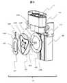
始めに、図1を用い、本発明における採血装置1の基本構成について説明する。 First, the basic configuration of the
図1は採血装置1の外観図である。図1では、採血装置1の内部構成を示すため、採血装置1の上部ケース100と下部ケース101は断面表示とする。採血装置1は、穿孔器112(図2)、採血管114(図2)と絆創膏116(図2)を内蔵する使い捨てのカートリッジ11と、カートリッジ11を保持するカートリッジケース110と、カートリッジホルダ11を動作させるための駆動機構12と、カートリッジホルダ11と駆動機構12を保持するための柱128と、駆動機構12の動力源となるモータ120と、指の先端甲側を圧迫固定するための指押さえ機構13と、指の根元側の周囲を締めつけるカフ151を内蔵する指締めつけ機構15と、指押さえ機構13と指締めつけ機構15を保持し、指を乗せる台となる指固定台14と、カフ151内の空気圧を調整するためのポンプ174(図8)、電磁弁173(図8)と圧力センサ172(図8)を備えた圧力調整機構17と、指押さえ機構13に固定された指先腹側を観察するためのカメラ162(図8)と、モータ120、圧力調整機構17とカメラ162の動作を制御するための制御機構16と、制御機構16への指示内容の入力や制御機構16からの出力結果を表示するためのインターフェイス160と、インターフェイス160を保持するインターフェイスホルダ161と、電源やデータ通信用のケーブルの接続部である外部接続部163で構成されている。 FIG. 1 is an external view of the
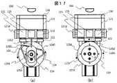
次に、図2を用い、本発明における採血装置1が使用するカートリッジ11の構成について説明する。図2(a)、図2(b)および図2(c)はそれぞれ、カートリッジ11の組図、外観図および断面図である。 Next, the configuration of the
カートリッジ11は、穿孔器112を保持する穿孔器ホルダ111と、採血管114を保持する採血管ホルダ113と、絆創膏116を保持する絆創膏ホルダ115を、カートリッジケース110内の穿孔器ホルダ用保持穴1110、採血管ホルダ用保持穴1130、絆創膏ホルダ用保持穴1150で保持する。穿孔器ホルダ用保持穴1110、採血管ホルダ用保持穴1130、絆創膏ホルダ用保持穴1150は貫通穴であるが、底側の直径が穿孔器ホルダ111、採血管ホルダ113、絆創膏ホルダ115の直径より小さいため、穿孔器ホルダ111、採血管ホルダ113、絆創膏ホルダ115は穿孔器ホルダ用保持穴1110、採血管ホルダ用保持穴1130、絆創膏ホルダ用保持穴1150から落下することはない。また採血の際に穿孔箇所の画像を取得するため、カートリッジケース110は光透過性であることが好ましい。 The
穿孔器112は穿刺針と穿刺針を内蔵するホルダで構成されている一回使用の皮膚穿刺用器具であり、穿孔器112の先1120を指に押し付けると、穿刺針が一瞬飛び出し指の皮膚及び毛細血管を穿孔する。採血管114は血液を吸収するための吸収パッド1140と容器で構成されている血液採取用の容器であり、指の穿孔箇所に吸収パッド1140を押しつけることで、穿孔箇所から出血した血液を採取する。絆創膏116は、粘着性のシートの中心に吸収性のパッドを備え、粘着面を上向きにして絆創膏ホルダ115に取り付ける。 The
図3は、採血装置1を用いた指からの採血工程のフローチャートである。フローチャートには各工程に対応する図番を記載している。採血装置1による採血は、(1)カートリッジ11のセット、(2)指の固定、(3)被験者情報と採血条件の入力(4)カートリッジ11のロットの読み取り、(5)カートリッジ11及び指156の初期位置の確認(6)カフ151の加圧による指の締めつけ、(7)穿孔器112による指の穿孔、(8)血液流出の確認、(9)採血管114による採血、(10)カフ151の減圧による指の締めつけの解放、(11)絆創膏116による止血の順に実施される。採血装置1の操作は被験者自らもしくは被験者以外の者でも実施可能である。図3のフローチャートに沿って採血装置1の採血工程について説明する。 FIG. 3 is a flowchart of a finger blood collecting process using the
(1)カートリッジ11のセット
図4は、採血装置1へのカートリッジ11の取り付け手順を示す。未使用のカートリッジ11は保管時の汚染防止のため、カートリッジ用蓋1100に覆われている。使用時には、採血装置1の上部ケース100を開け、カートリッジ用蓋1100を取り外したカートリッジ11をカートリッジホルダ121にセットする。カートリッジ11のセット後、上部ケース100を閉め固定用部品1001で上部ケース100を固定する。(1) Setting of
(2)指の固定
図5は、採血装置1への指156の固定手順を示す。始めに、指押さえ機構13を開き、指156を指締めつけ機構15の穴に挿入し、指先を指固定台14内の穴である採血窓140に置く。指156を採血窓140に置いたのち、指押さえ機構13を閉じることで指先を採血窓140に固定する。指押さえ機構13の指押さえ機構用マグネット135と指固定台14の指固定台用マグネット141の吸着により、指押さえ機構13が後の工程で開くことを防止する。(2) Fixation of Finger FIG. 5 shows a procedure for fixing the
図6は、指156を固定した際の自動分析装置1の上部断面図である。図6を用い、指156の固定時における自動分析装置1の各構成部品の詳細及び位置関係を説明する。 FIG. 6 is a cross-sectional top view of the
指押さえ機構13は、指156の先端(末節)を固定するための第一指先押さえ131と、指156の第一関節付近を固定するための第二指先押さえ132と、第一指先押さえ131と第二指先押さえ132を保持する指押さえ機構用ケース130で構成され、第一指先押さえ131と指押さえ機構用ケース130は第一指先押さえ用バネ133で連結され、第二指先押さえ132と指押さえ機構用ケース130は第二指先押さえ用バネ134で連結される。指156の固定時は、第一指先押さえ用バネ133と第二指先押さえ用バネ134のばね力により、第一指先押さえ131と第二指先押さえ132は指156を指固定台14に押し付ける。指は先端ほど細くなるため、指第一押さえ用バネ133のばね定数は第二指先押さえ用バネ134のばね定数より大きいことが好ましい。 The finger
指締めつけ機構15は、指156を空気圧により締めつけるカフ151とカフ151を保持するカフケースで構成される。指締めつけ機構15は指固定台14上を指の挿入方向に対し前後に動かすことができ、指固定台14と指締めつけ機構15は指締めつけ機構用バネ152により連結されている。指締めつけ機構用バネ152のばね力が指締めつけ機構15を指156の根元方向に押すため、被験者の指156を採血窓140に固定した際、被験者の指156の長さに関わらず、指締めつけ機構15は指156の根元(基節)まで動く。また、指締めつけ機構15のカフ150の内圧を上げることで、カフ150により指156を圧迫することができる。 The
さらに、指締めつけ機構15はマイク157を備えており、マイク157により指156の血流音を計測することが可能である。計測した血流音は後述したインターフェイス160に表示させることができる。 Furthermore, the
指押さえ機構13で指156を指固定台14に固定すると、指156の指先の腹が採血窓140より飛び出し、飛び出した指156の腹の下にカートリッジ11が配置される。また、カートリッジケース110は上方に数mm程度突出したヘリを有する形状である。カートリッジ11のカートリッジケース110と指固定台14との間隔を数mm以下とすることにより、指156の腹が指固定台とカートリッジ11で覆われた空間に位置付けられる状態となる。実際の採血では、指先の穿刺や採血の際に血液が噴出することや、採血後も穿刺箇所からの出血が止まらないことがあるため、採血装置の内部が被験者の血液で汚染される可能性があるが、血液による汚染はカートリッジケース110により防止される。カートリッジ自体は使い捨てであるため、一回の測定毎に交換されるため、採血装置内部が血液で汚染することはない。 When the
さらに、カートリッジケース110は光透過性のため、上部ケース100に固定されたカメラ162により、指156の指先の腹やカートリッジ11の状態を観察することが可能である。なお、光透過性を有する領域は、カートリッジケース110の一部のみとしても良い。ようは、カートリッジケース110の外部からカメラ等の手段によりカートリッジと指156との位置関係や指156の穿刺状態を確認できるように構成されていれば良い。 Further, since the
(3)被験者情報と採血条件の入力
図7は、指156固定後のインターフェイス160の表示画面である。採血装置1の操作者は、インターフェイス160から(a)被験者情報及び採血条件入力、(b)指156やカートリッジ11の状態確認、(c)採血工程の実施・一時停止・停止の操作、(d)指の血流の状態確認を実施することができる。図7では、インターフェイス160をタブレットPCの形状で示しているが、PC,タブレットPCやスマートフォンを用いてもよく、もしくは採血装置1に据え付けされたものでもよい。インターフェイス160にタブレットPCやスマートフォンを用いることの利点は、インターフェイス160を採血装置1から分離して使用することができることであり、被験者以外が採血装置1を操作する際に、被験者が採血の様子を不用意に見ることを防止することができる。(3) Input of Subject Information and Blood Collection Conditions FIG. 7 is a display screen of the
操作者はインターフェイス160から、被験者情報1604と採血条件1605を入力する。被験者情報1604は被験者の年齢、血液型、血圧などの採血時における個人情報であり、採血条件は指の締めつけ圧や穿孔、採血などのタイミングなどの採血工程に関する情報である。 The operator inputs
(4)カートリッジ11のロットの読み取り
カートリッジ11のロット情報をバーコード117としてカートリッジケース110上に記録することで、カメラ162で取得した画像1620からカートリッジ11のロット情報を読み込むことが可能である。この工程により、先の工程で入力した被験者情報と採血条件をカートリッジ11のロット情報を結びつけることができる。(4) Reading the lot of the
(5)カートリッジ11及び指156の初期位置の確認
カートリッジ11と指156の初期位置を確認するため、カメラ162で撮影した画像1620をインターフェイス160に表示させる。カートリッジ11の初期位置の確認は、指156の真下に穿孔器112があることを確認することで実施する。また、カートリッジ11が初期位置のときにバーコード117が見えることで確認してもよい。指156の初期位置の確認は、指156が採血窓140より見えることで確認する。なお、カメラ162で動画を撮像しインターフェイス160に表示させるようにしても良い。初期位置の確認後、コントロールボタン1600の実行ボタン1601、一時停止ボタン1602、停止ボタン1603を押すことで駆動装置を制御し、採血の実施・一時停止・停止を実施することができる。(5) Confirmation of initial positions of the
(6)カフ151(図6)の加圧による指の締めつけ
指156の血流音をマイク157(図6)で取得し、インターフェイス160の画面内の血流音の経時変化1550で血流音の有無を確認することができる。カフ151(図6)の内圧を上げ、指を締めつける力が強くなると、ある時点で指156を流れる血流が止まり血流音もなくなる。血流音が無くなった時点が最適の締めつけ圧とみなし、後の穿孔の工程に移る。タイミングの制御はインターフェイス160を参照しながら被験者自信が判断しても良いし、コンピュータが予め設定された基準に基づいて判断しても良い。(6) Finger tightening by pressurizing the cuff 151 (FIG. 6) The blood flow sound of the
図8は、カフ151の内圧を調整するためのカフ内圧調整機構であり、カフ内圧調整機構はカフ用圧力センサ152、カフ用電磁弁153、カフ用ポンプ154と、カフ151、カフ用圧力センサ152、カフ用電磁弁153、カフ用ポンプ154を連結する送気管1510で構成される。カフ用圧力センサ152でカフ151の内圧を常時計測することにより、カフ151の内圧を指定した条件で調節することが可能であり、カフ151の異常な加圧を防止することができる。 FIG. 8 shows a cuff internal pressure adjusting mechanism for adjusting the internal pressure of the
(7)穿孔器112による指の穿孔から(11)絆創膏116による止血
指156の締めつけ後、指の穿孔、採血、止血の工程を駆動機構12の機械的しくみにより実施する。図9、図10、図11はそれぞれ駆動機構12の組図、正面図、右側面図である。これらの図を用い、駆動機構12の構成および機械的しくみについて説明する。(7) From the perforation of the finger by the
駆動機構12は、ラックギア122、欠歯ギア123、溝カム124、押し棒部品125、カートリッジホルダ121、柱128、レール1210で構成されている。カートリッジホルダ121はラックギア122を備え、レール1210上を動くように配置されている。欠歯ギア123と溝カム124はシャフト129を共通の回転軸とし、シャフト129は柱128に固定されている。欠歯ギア123とラックギア122はラック・アンド・ピニオンの位置関係であり、ラックギア122と欠歯ギア123の穿孔―採血管ギア1230もしくは採血―止血間ギア1231がかみ合う位置関係のとき、モータ120(図1)によりシャフト129が回転すると、それに伴う欠歯ギア123の回転によりラックギア122はレール1210方向に力を受け、ラックギア122が受ける力によりカートリッジホルダ121はレール1210上を動く。 The
また、溝カム124の中心凸部1241と押し棒部品125の中心穴部1251は重なるように構成され、また押し棒部品125の溝用突起1250は溝カム124の溝1241にはまるように構成されているため、溝カム124は押し棒部品125の溝カムとして作用する。また、押し棒部品125は、穿孔器ホルダ111、採血管ホルダ113、絆創膏ホルダ115の各中心軸を含む平面上に配置されている。 Further, the central
モータ120(図1)によりシャフト129が回転すると、それに伴う溝カム124の回転により押し棒部品125は上下に動き、カートリッジホルダ121の位置によって穿孔器ホルダ111もしくは、採血管ホルダ113もしくは、絆創膏ホルダ115を上下に動かす。 When the
図12〜図20は指の穿孔、採血、止血の各工程における駆動機構12の正面図である。押し棒部品125、溝カム124、欠歯ギア123の位置関係を示すため、押し棒部品125と溝カム124を含む正面図を(a)とし、押し棒部品125と溝カム124を含まない正面図を(b)として示す。 12 to 20 are front views of the
図12〜図13は指の穿孔前から穿孔までの駆動機構12の状態を示す。シャフト129の回転に伴い溝カム124と欠歯ギア123が回転する。このときシャフト129の中心軸と押し棒部品125の溝用突起1250の間隔が広がるため、押し棒部品125は上方向に動き穿孔器ホルダ111を押す動作を行う。穿孔器112と指156が接触し、穿孔器112が一定以上の負荷を受けると、穿孔器112の穿孔針が飛び出し指156の皮膚及び毛細血管を穿刺する。このときラックギア122は欠歯ギア123の穿孔時欠歯部1233と対向しているため、カートリッジホルダ121は動かない。 12 to 13 show states of the
図14は指の穿孔後から採血直前までの駆動機構12の状態を示す。溝カム124と欠歯ギア123の回転により、欠歯ギア123の穿孔―採血間ギア1230とラックギア122がかみ合いカートリッジホルダ121は図中右から左に移動する。穿孔―採血間ギア1230の長さは穿孔器ホルダ111と採血管ホルダ113の中心軸の距離に等しいため、この動きにより採血管ホルダ113の中心軸と押し棒部品125の押し棒1252が重なる配置になる。このときシャフト129の中心軸と押し棒部品125の溝用突起1250の間隔は最も狭い間隔を保ちながら変わらないため、押し棒部品125が穿孔器ホルダ111や採血管ホルダ113を押すことはない。 FIG. 14 shows a state of the
図15〜図16は採血前から採血までの駆動機構12の状態を示す。溝カム124と欠歯ギア123の回転により、シャフト129の中心軸と押し棒部品125の溝用突起1250の間隔が広がるため、押し棒部品125は上方向に動き採血管ホルダ113を押す動作を行う。採血管114と指156が接触することで血液1560は採血管114に採取される。このときラックギア122は欠歯ギア123の採血時欠歯部1234と対向しているため、カートリッジホルダ121は動かない。 15 to 16 show states of the
また、採血完了後にカフ151(図6、8)を減圧し指の締め付けを解放することで、更なる出血を防止する。 Further, after the blood collection is completed, the cuff 151 (FIGS. 6 and 8) is decompressed and the tightening of the finger is released to prevent further bleeding.
図17は採血後から止血直前までの駆動機構12の状態を示す。溝カム124と欠歯ギア123の回転により、欠歯ギア123の採血―止血間ギア1232とラックギア122がかみ合いカートリッジホルダ121は図中右から左に移動する。採血―止血間ギア1232の長さは採血管ホルダ113と絆創膏ホルダ115の中心軸の距離に等しいため、この動きにより絆創膏ホルダ115の中心軸と押し棒部品125の押し棒1252が重なる配置になる。このときシャフト129の中心軸と押し棒部品125の溝用突起1250の間隔は最も狭い間隔を保ち変わらないため、押し棒部品125が採血管ホルダ113や絆創膏ホルダ115を押すことはない。 FIG. 17 shows the state of the
図18〜図20は止血前から止血までの駆動機構12の状態を示す。溝カム124と欠歯ギア123の回転により、シャフト129の中心軸と押し棒部品125の溝用突起1250の間隔が広がるため、押し棒部品125は上方向に動き絆創膏ホルダ115を押す動作を行う。絆創膏116と指156が接触することで絆創膏116を指156に貼りつけ止血を行う。このときラックギア122は欠歯ギア123の止血時欠歯部1235と対向しているため、カートリッジホルダ121は動かない。 18 to 20 show the state of the
採血装置1では、モータ120の回転を制御することで穿孔から止血までの各工程の処理時間や移行のタイミングを調節することが可能である。例えば、指156の穿孔後に、指156の画像1620(図21)から血液1560の有無を確認することで十分な血量を確認したのち採血工程に移ることが可能である。血液1560が確認できないときはカフ151を加圧し指156を締めつけ、出血を促す。 In the
図22は、採血量を増大するためのカフ151の内圧調整方法の一つの例を示す。指156(図8)の穿孔前に、カフ151の内圧を上昇させることで指156を圧迫する。このときのカフ156の内圧をPとする。指156の圧迫後、ランセット112(図2)で指156を穿孔する。指156の穿孔後、カフ156の内圧を0に戻し、一定間隔でカフ151の内圧の増減を繰り返すことで、指の圧迫と解放を繰り返す。この動作により、指156の穿孔箇所から流出する血液の量を増大することが可能である。血液の採血後、カフ156の内圧を0に戻し指を解放することで、採血後の出血を抑制する。 FIG. 22 shows one example of a method of adjusting the internal pressure of the
図23は、穿孔器ホルダ111、採血管ホルダ113、絆創膏ホルダ115の断面図である。採血から止血までの工程にて、駆動機構12による押し棒部品125の移動量よりも各ホルダ113、114、115と指固定台14の底面までの間隔が短い場合は、各ホルダ113、114、115がシャフト129(図9)の回転を阻害する。そのため、各ホルダ113、114、115に押し棒部品125の過度の移動を吸収するための機能が必要になる。以下それぞれのホルダについて説明する。図23(a)は穿孔器ホルダ111の断面図であり、穿孔器ホルダ111は穿孔器ホルダケース1110と穿孔器ホルダ底部品1111と穿孔器ホルダ用バネ1112で構成される。穿孔器ホルダ用バネ1112が収縮することにより押し棒部品125の過度の移動を吸収する。図23(b)は採血管ホルダ113の断面図であり、採血管ホルダ上部ケース1130、採血管ホルダ下部ケース1131、採血管ホルダ用バネ1132、採血管ホルダ用緩衝材1133で構成される。採血管ホルダ用緩衝材1133は発泡性ウレタンなどの吸収材であり、採血管ホルダ用バネ1132より小さい力で収縮する性質がある。採血管114と指156の接触後に採血管114がさらに上に移動しても、採血管ホルダ用緩衝材1133の収縮により指156に余計な負荷をかけない。また、採血管ホルダ用緩衝材1133で吸収することができない押し棒部品125の過度な移動は採血管ホルダ用バネ1132で吸収する。図23(c)は絆創膏ホルダ115の断面図であり、絆創膏ホルダ上部ケース1150、絆創膏ホルダ下部ケース1151、絆創膏ホルダ用バネ1152、絆創膏ホルダ用緩衝材1153で構成される。絆創膏116と指156の接触後に絆創膏ホルダ115が上に移動すると、絆創膏ホルダ用緩衝材1153が指156の形に沿って変形する。この変形により絆創膏115を指156の全面に貼りつけることができる。 FIG. 23 is a cross-sectional view of the
指の内部の圧力と指の外部の圧力の差を大きくすることで、指からの採血量は増大するため、先の実施例では、指156の根元をカフ151で圧迫することで採血量を増やした。本実施例では指の外部の圧力を減少させることでさらに採血量を増やすための方法を示す。 By increasing the difference between the pressure inside the finger and the pressure outside the finger, the amount of blood collected from the finger increases. Therefore, in the previous embodiment, the base of the
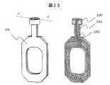
図24は、採血管ホルダ213の外観図及び断面図である。採血管ホルダ213は、採血管ホルダ用ケース2130、採血管ホルダ用下部緩衝材2133、採血管ホルダ用上部緩衝材2134で構成されており、さらに採血管114と採血管ホルダ213の間から採血管ホルダの底面に至るまでの吸気流路2135を備える。 FIG. 24 is an external view and a cross-sectional view of the blood
図25は、押し棒部品225の外観図及び断面図である。押し棒部品225は、内部に管路2253を備え、さらに押し棒2252の先端に押し棒緩衝材2254を備える。 FIG. 25 is an external view and a cross-sectional view of the
図26は採血工程における各部品の位置関係を示す図である。図25を用い、採血管ホルダ213と押し棒部品225による指外部の圧力減少のしくみ説明する。 FIG. 26 is a diagram showing the positional relationship of each component in the blood collecting step. The mechanism of reducing the pressure on the outside of the finger by the blood
採血の際、採血管ホルダ用上部緩衝材2134が指固定台14の底面に接触するまで押し棒部品225で採血管ホルダ213を押しあげた後、駆動機構12の動作を一時停止させる。このとき採血管ホルダ上部緩衝材2134は変形により指固定台14の底面に密着し、同様に押し棒緩衝材2254も変形により採血管ホルダ213の底面に密着する。さらに押し棒部品225の内部の管路2253は吸気流路2254に接続し、管路2253および吸気流路2254を介して、吸気ポンプ2256と電磁弁2257と連結しているため、図26の状態で吸気ポンプ2256を動作させると管路2253を介して指156の周囲の気圧を下げることができる。この動作により、指の内部の圧力と指の外部の圧力の差をさらに大きくし、指からの採血量を増やすことができる。 When collecting blood, the blood
採血完了後に吸気ポンプ2256の動作を停止し電磁弁2257を解放することで、指の外部の圧力や押し棒部品225の内部の管路2253の圧力は大気圧も戻る。それにより採血管ホルダ225は指固定台14の底面から外れ、また、押し棒緩衝材2254も採血管ホルダ213の底面から外れる。 By stopping the operation of the
その他の工程は実施例1と同様であるため詳細な説明は省略する。本実施例によれば、圧力変化により穿刺痕から迅速に血液を収集することができる。 The other steps are similar to those of the first embodiment, and detailed description thereof will be omitted. According to the present embodiment, blood can be quickly collected from the puncture scar due to pressure change.
先の実施例では、カフ151で指156の全周囲を圧迫し血流を止め、採血を実施した(図6、図7、図8)。本実施例では、指の周囲の一部を締めつけることで指の血流を止め、採血する方法を示す。 In the previous example, the
図27(a)は、指156の甲側の半周面のみを締めつけることが可能な指締めつけ機構25の外観図であり、図27(b)は、カフ251による指の締めつけ効果を示すための指圧迫機構25及び指156の断面図である。指締めつけ機構25は、指156の甲側の半周面を包むカフ251とカフ251を保持するカフケース250で構成される。指156は、中心に骨1560と指屈筋1561があり、その周囲を皮下組織1562が覆うような構造をしている。さらに指動脈1563は指の掌側に位置し、指静脈1564は指の甲側に位置する。 27A is an external view of the
カフ251により指156の甲側の半周面を圧迫すると、指動脈1563の断面積は変わらないが、指静脈1564の断面積はカフ251による圧迫により小さくなり、血流が止まる。この状態で指先を穿孔すると、指静脈1564は閉塞しているが指動脈1563は閉塞していないため、指156の全周囲を圧迫する場合と比べて血液が止まりにくく、採血量を増大することが可能になる。 When the
先の実施例では、指の穿孔、採血、止血の工程を自動実施する装置及び方法を示した。本実施例では、指の消毒、指の穿孔、採血、止血の工程を自動実施する装置及び方法を示す。 In the previous example, the apparatus and method for automatically performing the steps of finger perforation, blood collection, and hemostasis were shown. This embodiment shows an apparatus and method for automatically performing the steps of finger disinfection, finger perforation, blood collection, and hemostasis.
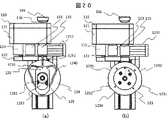
図28(a)、図28(b)はそれぞれ、カートリッジ21の組図、外観図である。 28A and 28B are an assembly view and an external view of the
カートリッジ21は、消毒器219を保持する消毒器ホルダ218と、穿孔器212を保持する穿孔器ホルダ211と、採血管214を保持する採血管ホルダ213と、絆創膏216を保持する絆創膏ホルダ215を保持する。 The
消毒器219は消毒用エタノールを含む脱脂綿を先端に備えた器具であり、採血装置1により、先端を指の穿孔箇所に押しつけることで消毒する。 The disinfecting
その他の工程は実施例1と同様であるため詳細な説明は省略する。本実施例によれば、指の穿孔の前に消毒器による指の消毒を実施することができる The other steps are similar to those of the first embodiment, and detailed description thereof will be omitted. According to this embodiment, the disinfection of the finger by the disinfecting device can be performed before the perforation of the finger.
1:採血装置、11:カートリッジ、12:駆動機構、13:指押さえ機構、14:指固定台、15:指締めつけ機構、16:制御機構、17:圧力調整機構、100:上部ケース、101:下部ケース、110:カートリッジケース、111:穿孔器ホルダ、112:穿孔器、113:採血管ホルダ、114:採血管、115:絆創膏ホルダ、116:絆創膏、120:モータ、121:カートリッジホルダ、122:ラックギア、123:欠歯ギア、124:溝カム、125:押し棒部品、128:柱、129:シャフト、131:第一指押さえ、132:第二指押さえ、1333:第一指押さえ用バネ、134:第二指押さえ用バネ、140:採血窓、151:カフ、152:カフ用圧力センサ、153:カフ用電磁弁、154:カフ用ポンプ、156:指、157:マイク、160:インターフェイス、161:インターフェイスホルダ、163:外部接続部、162:カメラ、172:圧力センサ、173:電磁弁、174:ポンプ
213:採血管ホルダ、225:押し棒部品1: Blood collection device, 11: Cartridge, 12: Drive mechanism, 13: Finger pressing mechanism, 14: Finger fixing base, 15: Finger tightening mechanism, 16: Control mechanism, 17: Pressure adjusting mechanism, 100: Upper case, 101: Lower case, 110: Cartridge case, 111: Punch holder, 112: Punch, 113: Blood collection tube holder, 114: Blood collection tube, 115: Bandage plaster holder, 116: Bandage plaster, 120: Motor, 121: Cartridge holder, 122: Rack gear, 123: toothless gear, 124: groove cam, 125: push rod part, 128: pillar, 129: shaft, 131: first finger press, 132: second finger press, 1333: first finger press spring, 134: second finger pressing spring, 140: blood sampling window, 151: cuff, 152: cuff pressure sensor, 153: cuff solenoid valve, 154: cuff pump, 156: finger, 157: microphone, 160: interface, 161: Interface holder, 163: External connection part, 162: Camera, 172: Pressure sensor, 173: Solenoid valve, 174: Pump 213: Blood collection tube holder, 225: Push rod part
Claims (22)
Translated fromJapanese前記穿刺対象部位と前記カートリッジの水平方向の相対位置を変化させ、かつ、前記穿刺対象部位と前記穿孔針、前記容器及び前記シールの垂直方向の相対位置を変化させる駆動機構と、
前記穿刺対象部位の一部を固定するための第一の固定機構と、
前記穿刺対象部位の別の一部を圧迫するための圧迫機構を備えると共に位置が可変である第二の固定機構を備えていることを特徴とする採血装置。A perforation needle holder having a perforation needle for puncturing a puncture target site of a living body, a container holder having a container for collecting body fluid flowing out from a puncture trace of the puncture target site, a seal holder having a seal for sealing the puncture trace, And a cartridge having a cartridge case that movably holds the piercing needle holder, the container holder, and the seal holder,
A drive mechanism that changes the horizontal relative positions of the puncture target site and the cartridge, and changes the vertical relative positions of the puncture target site and the piercing needle, the container, and the seal,
A first fixing mechanism for fixing a part of the puncture target site,
A blood collecting apparatus comprising a compression mechanism for compressing another part of the puncture target site and a second fixing mechanism whose position is variable.
前記第二の固定機構を前記第一の固定機構から離れる方向に付勢する付勢手段を有する、採血装置。The blood collection device according to claim 1,
A blood collecting device having a biasing unit that biases the second fixing mechanism in a direction away from the first fixing mechanism.
前記第一の固定機構で保持された前記穿刺対象部位の一部を露出させる孔を有する台を備え、
前記第一の固定機構は、前記穿刺対象部位を固定している状態で前記孔に向けて前記穿刺対象部位を押し付ける押さえ手段を有する、採血装置。The blood collection device according to claim 1,
A pedestal having a hole exposing a part of the puncture target portion held by the first fixing mechanism,
The said 1st fixing mechanism is a blood collection apparatus which has the pressing means which presses the said puncture target site toward the said hole in the state which fixed the said puncture target site.
前記穿刺対象部位は指の末節の腹であり、
前記第一の固定機構と前記第二の固定機構は指の長さ方向に並んで配置しており、
前記第二の固定機構は指の長さ方向に移動可能である、採血装置。The blood collection device according to claim 1,
The puncture target site is the belly of the distal node of the finger,
The first fixing mechanism and the second fixing mechanism are arranged side by side in the length direction of the finger,
The blood collecting device, wherein the second fixing mechanism is movable in the length direction of the finger.
前記第一の固定機構で保持された指の一部を露出させる孔を有する台を備え、
前記第一の固定機構は、指を固定している状態で前記孔に向けて指を押し付ける押さえ手段と、前記押さえ手段を収容する指押さえケースと、を有する、採血装置。The blood collection device according to claim 4,
A stand having holes for exposing a part of the fingers held by the first fixing mechanism;
The said 1st fixing mechanism is a blood collection apparatus which has the pressing means which presses a finger toward the said hole in the state which fixed the finger, and the finger pressing case which accommodates the said pressing means.
前記押さえ手段を前記指押さえケースに連結する複数のバネ部材を備え、
固定される指の先端に近い位置の押さえ手段を連結するバネ部材は、固定される指の先端に遠い位置の押さえ手段を連結するバネ部材よりも大きいバネ定数を有する、採血装置。The blood sampling device according to claim 5,
A plurality of spring members for connecting the pressing means to the finger pressing case,
The blood collecting device, wherein the spring member that connects the pressing means located near the tip of the fixed finger has a spring constant larger than that of the spring member that connects the pressing means located far from the fixed tip of the finger.
前記カートリッジは使い捨てである、採血装置。The blood collection device according to claim 1,
The blood collecting device, wherein the cartridge is disposable.
前記カートリッジケースは下面が開放されており、
前記駆動機構は前記カートリッジケースに保持された前記穿孔針ホルダ、前記容器ホルダ、及び前記シールホルダを下から押し上げる押し上げ部材を有する、採血装置。The blood collection device according to claim 1,
The lower surface of the cartridge case is open,
The blood collection device, wherein the drive mechanism has a push-up member that pushes up the perforation needle holder, the container holder, and the seal holder held from the cartridge case from below.
前記穿刺対象部位の血流音を集音する集音機を備える、採血装置。The blood collection device according to claim 1,
A blood collecting device comprising a sound collector that collects blood flow sound of the puncture target site.
前記第一の固定機構で保持された指の一部を露出させる孔を有する台と、
前記孔から露出した前記穿刺対象部位を撮像する画像取得手段を備える、採血装置。The blood collection device according to claim 1,
A table having a hole for exposing a part of the finger held by the first fixing mechanism,
A blood collection device comprising image acquisition means for capturing an image of the puncture target site exposed from the hole.
前記駆動機構の動作を制御する制御ボタンを表示するインターフェイスを有する、採血装置。The blood collection device according to claim 1,
A blood collection device having an interface displaying control buttons for controlling the operation of the drive mechanism.
前記インターフェイスは、被験者情報、採血条件情報、前記穿刺対象部位と前記カートリッジの状態情報、血流の状態情報の少なくともいずれかの情報を表示する、採血装置。The blood collection device according to claim 11,
The interface is a blood sampling apparatus that displays at least one of subject information, blood collection condition information, status information of the puncture target site and the cartridge, and blood flow status information.
前記第一の固定機構で保持された前記穿刺対象部位の一部を露出させる孔を有する台を有し、
前記カートリッジケースは上向きに突出したヘリを持ち、
前記孔から露出した前記穿刺対象部位の一部は、前記台および前記カートリッジケースで囲まれた空間に位置付けられる、採血装置。The blood collection device according to claim 1,
A stand having a hole exposing a part of the puncture target portion held by the first fixing mechanism,
The cartridge case has a helicopter protruding upward,
A part of the puncture target site exposed from the hole is positioned in a space surrounded by the base and the cartridge case.
前記採血装置は、
生体の穿刺対象部位を穿刺する穿孔針を有する穿孔針ホルダ、前記穿刺対象部位の穿刺痕より流出する体液を捕集する容器を有する容器ホルダ、前記穿刺痕を封止するシールを有するシールホルダ、及び前記穿孔針ホルダ、前記容器ホルダ並びに前記シールホルダを移動可能に保持するカートリッジケースを有するカートリッジと、
前記カートリッジの水平方向の位置を変化させ、かつ、前記穿孔針、前記容器及び前記シールの垂直方向の位置を変化させる駆動機構と、
前記穿刺対象部位の一部を固定するための第一の固定機構と、
前記穿刺対象部位の別の一部を圧迫するための圧迫機構を備えると共に位置が可変である第二の固定機構を備え、
前記作動方法は、
前記第一の固定機構に前記穿刺対象部位が固定され、前記第二の固定機構に前記穿刺対象部位の別の一部が固定された後、前記圧迫機構が作動する工程と、
前記駆動機構により、前記穿孔針を上方に移動させる工程と、
前記駆動機構により、前記採血装置に取り付けられた前記カートリッジを水平方向に移動させる工程と、
前記駆動機構により、前記容器を上方に移動させる工程と、
前記駆動機構により、前記カートリッジをさらに水平方向に移動させる工程と、
前記圧迫機構の作動を解除する工程と、
前記駆動機構により、前記シールを上方に移動させる工程と、を有する採血装置の作動方法。A method of operating a blood collection device,
The blood collecting device is
A perforation needle holder having a perforation needle for puncturing a puncture target site of a living body, a container holder having a container for collecting body fluid flowing out from a puncture trace of the puncture target site, a seal holder having a seal for sealing the puncture trace, And a cartridge having a cartridge case that movably holds the piercing needle holder, the container holder, and the seal holder,
A drive mechanism for changing the horizontal position of the cartridge and for changing the vertical positions of the piercing needle, the container and the seal;
A first fixing mechanism for fixing a part of the puncture target site,
A second fixing mechanism having a variable position and having a compression mechanism for compressing another part of the puncture target site,
The operating method is
After the puncture target site is fixed to the first fixing mechanism, and another part of the puncture target site is fixed to the second fixing mechanism, the compression mechanism is operated,
The step of moving the piercing needle upward by the drive mechanism,
A step of horizontally moving the cartridge attached to the blood collecting device by the drive mechanism;
Moving the container upward by the drive mechanism,
Moving the cartridge further in the horizontal direction by the drive mechanism,
Releasing the operation of the compression mechanism,
And a step of moving the seal upward by the drive mechanism.
前記採血装置は、前記穿刺対象部位の血流音を計測するマイクをさらに備え、
前記圧迫機構が作動する工程の間に、前記マイクにより前記穿刺対象部位の血流音を計測し、前記血流音が消失した時に、前記穿孔針を上方に移動させる工程に移行する、採血装置の作動方法。The method for operating the blood collection device according to claim 14,
The blood collection device further includes a microphone for measuring blood flow sound of the puncture target site,
During the process of the compression mechanism is operated, the blood flow sound of the puncture target sites were measured by themicrophone,sometimesbefore the winding flow sound islost, the process proceeds to step of moving the perforating needle upwards, blood collection How the device works.
前記カートリッジを取り付けた後、前記穿刺対象部位と前記カートリッジの位置を画像または動画で確認すると共に、
前記穿孔針を上方に移動させる工程の後、前記穿刺痕からの体液の流出を画像取得手段で確認したのち、前記駆動機構により、前記容器を上方に移動させる、採血装置の作動方法。The method for operating the blood collection device according to claim 14,
After attaching the cartridge, confirm the position of the puncture target site and the cartridge with an image or a moving image,
After the step of moving the piercing needle upward, after confirming the outflow of the body fluid from the puncture mark by the image acquisition means, the driving mechanism moves the container upward to operate the blood sampling apparatus.
前記容器ホルダは、前記容器ホルダの内部に貫通した貫通路を底面に有し、
前記押し上げ部材は、端部が開放された第一の口と第二の口を連結する内部流路を有し、
流路を介して前記第二の口に連結可能な吸引ポンプを備え、
前記押し上げ部材が前記容器ホルダを下から押し上げる際に、前記第一の口と前記容器ホルダに設けられた貫通路が連結するように配置され、前記第二の口は前記流路を介して前記吸引ポンプと接続される、採血装置。The blood collecting device according to claim 8,
The container holder has a through path on the bottom surface that penetrates the inside of the container holder,
The push-up member has an internal flow path connecting the first opening and the second opening, the ends of which are open,
A suction pump connectable to the second port through a flow path,
When the pushing-up member pushes up the container holder from below, the first port and the through-passage provided in the container holder are arranged so as to be connected to each other, and the second port is disposed through the flow path. A blood collection device connected to a suction pump.
前記第一の固定機構で保持された指の一部を露出させる孔を有する台を備え、
前記容器ホルダの上端部および前記押し上げ部材の上端部に圧縮変形可能な緩衝材を有し、
前記押し上げ部材が前記容器ホルダを前記台に押しあてたとき、前記穿刺対象部位の周囲は前記容器ホルダと前記台により密閉され、さらに前記密閉された空間は、前記容器ホルダの底面の貫通路を介し、前記吸引ポンプに連結する、採血装置。The blood collecting device according to claim 17,
A stand having holes for exposing a part of the fingers held by the first fixing mechanism;
The upper end of the container holder and the upper end of the push-up member has a cushioning material capable of compression deformation,
When the pushing-up member presses the container holder against the table, the periphery of the puncture target site is sealed by the container holder and the table, and the sealed space is a through passage of the bottom surface of the container holder. A blood collection device connected to the suction pump via the blood collection device.
前記吸引ポンプにより前記密閉された空間を減圧することにより、前記穿刺痕より流出する体液量を制御する、採血装置。The blood collection device according to claim 18,
A blood collection device that controls the amount of body fluid flowing out from the puncture mark by reducing the pressure in the closed space with the suction pump.
前記穿孔針が前記穿刺対象部位を穿刺した後、当該穿刺対象部位の別の一部の圧迫と解放を繰り返すように前記圧迫機構を制御する制御機構を備える、採血装置。The blood collection device according to claim 1,
A blood collection device comprising a control mechanism that controls the compression mechanism so as to repeatedly press and release another part of the puncture target site after the puncture needle punctures the puncture target site.
前記圧迫機構は、指の節の背側を圧迫する、採血装置。The blood collection device according to claim 4,
The blood collection device, wherein the compression mechanism presses the dorsal side of the node of the finger.
前記カートリッジケースはさらに、生体の前記穿刺対象部位を消毒する消毒器を有する消毒器ホルダを保持する、採血装置。The blood collection device according to claim 1,
The cartridge case further holds a disinfecting device holder having a disinfecting device for disinfecting the puncture target part of the living body.
Priority Applications (2)
| Application Number | Priority Date | Filing Date | Title |
|---|---|---|---|
| JP2016122241AJP6735161B2 (en) | 2016-06-21 | 2016-06-21 | Blood collection device and method of operating blood collection device |
| PCT/JP2017/021076WO2017221698A1 (en) | 2016-06-21 | 2017-06-07 | Blood collecting device and blood collecting method |
Applications Claiming Priority (1)
| Application Number | Priority Date | Filing Date | Title |
|---|---|---|---|
| JP2016122241AJP6735161B2 (en) | 2016-06-21 | 2016-06-21 | Blood collection device and method of operating blood collection device |
Publications (3)
| Publication Number | Publication Date |
|---|---|
| JP2017225519A JP2017225519A (en) | 2017-12-28 |
| JP2017225519A5 JP2017225519A5 (en) | 2019-02-07 |
| JP6735161B2true JP6735161B2 (en) | 2020-08-05 |
Family
ID=60784683
Family Applications (1)
| Application Number | Title | Priority Date | Filing Date |
|---|---|---|---|
| JP2016122241AActiveJP6735161B2 (en) | 2016-06-21 | 2016-06-21 | Blood collection device and method of operating blood collection device |
Country Status (2)
| Country | Link |
|---|---|
| JP (1) | JP6735161B2 (en) |
| WO (1) | WO2017221698A1 (en) |
Families Citing this family (21)
| Publication number | Priority date | Publication date | Assignee | Title |
|---|---|---|---|---|
| JP7104026B2 (en) | 2016-08-24 | 2022-07-20 | ベクトン・ディキンソン・アンド・カンパニー | Device for taking blood samples |
| JP6994910B2 (en)* | 2017-11-13 | 2022-01-14 | 株式会社日立ハイテク | How to operate the blood collection device and blood collection device |
| CN109846495B (en)* | 2019-02-23 | 2024-08-30 | 山东大学齐鲁医院 | Auxiliary device for peripheral blood collection |
| CN109662721B (en)* | 2019-02-28 | 2024-02-02 | 吉林大学 | Finger side pushing device for full-automatic fingertip blood sampling |
| JP7157711B2 (en)* | 2019-07-19 | 2022-10-20 | 株式会社日立ハイテク | Blood collection device |
| CN113040767A (en)* | 2019-12-26 | 2021-06-29 | 郝云玲 | Peripheral blood collection system |
| CN111467047A (en)* | 2020-04-03 | 2020-07-31 | 郝瑞翠 | Clinical examination is with blood sampling auxiliary device |
| CN111616719B (en)* | 2020-06-03 | 2022-08-09 | 日照市中心血站 | Automatic blood fat device of testing of clinical laboratory |
| CN112904022B (en)* | 2021-03-05 | 2024-07-16 | 上海玮驰仪器有限公司 | Antibody detection kit and application method thereof |
| CN113317786B (en)* | 2021-05-31 | 2023-04-11 | 上海交通大学医学院附属瑞金医院 | Automatic finger bloodletting instrument of children with entertainment function |
| EP4362791A4 (en)* | 2021-06-29 | 2025-04-30 | Becton, Dickinson and Company | Capillary blood collection device |
| CN113425296B (en)* | 2021-08-02 | 2022-07-08 | 西南医科大学 | A batch type rapid blood sampler suitable for medical pathology detection |
| CN113648884B (en)* | 2021-08-19 | 2024-03-12 | 武汉伯美帝科生物医疗科学技术有限公司 | Automatic shaking mechanism, intelligent blood sampling instrument and automatic shaking method |
| JP7660051B2 (en)* | 2021-09-29 | 2025-04-10 | 株式会社日立製作所 | Blood collection system and blood collection method |
| CN113884358A (en)* | 2021-10-09 | 2022-01-04 | 壹生检康(杭州)生命科技有限公司 | Preparation method of dried blood tablets |
| CN114145740B (en)* | 2021-12-13 | 2024-01-05 | 焦作市中心血站 | Can keep quick hemostix of blood sampling sample |
| CN114451893B (en)* | 2022-01-28 | 2024-01-09 | 医谷(滁州)航空医疗研究院有限公司 | Semi-automatic operation panel that draws blood convenient to operation |
| CN116831578B (en)* | 2023-06-14 | 2024-01-23 | 延边大学 | Hemostix for medical pathology detection |
| CN116570280B (en)* | 2023-06-26 | 2023-12-15 | 刘文波 | Blood collection system is used in clinical examination |
| WO2025004792A1 (en) | 2023-06-28 | 2025-01-02 | 株式会社日立ハイテク | Blood collection device |
| WO2025126116A1 (en)* | 2023-12-13 | 2025-06-19 | Vital Biosciences Inc. | Blood drawing device and method of collecting blood sample |
Family Cites Families (4)
| Publication number | Priority date | Publication date | Assignee | Title |
|---|---|---|---|---|
| US10631771B2 (en)* | 2008-01-07 | 2020-04-28 | Morteza Naghavi | Methods and apparatus for blood sampling |
| CA2793554C (en)* | 2010-03-19 | 2018-04-03 | Atomo Diagnostics Pty Limited | Bodily fluid diagnostic system |
| WO2013041704A1 (en)* | 2011-09-22 | 2013-03-28 | Sanofi-Aventis Deutschland Gmbh | Detecting a blood sample |
| JP2015154906A (en)* | 2014-01-20 | 2015-08-27 | 昌樹 上田 | Simple blood glucose level measuring device (two-way support for right-handed and left-handed users) |
- 2016
- 2016-06-21JPJP2016122241Apatent/JP6735161B2/enactiveActive
- 2017
- 2017-06-07WOPCT/JP2017/021076patent/WO2017221698A1/ennot_activeCeased
Also Published As
| Publication number | Publication date |
|---|---|
| WO2017221698A1 (en) | 2017-12-28 |
| JP2017225519A (en) | 2017-12-28 |
Similar Documents
| Publication | Publication Date | Title |
|---|---|---|
| JP6735161B2 (en) | Blood collection device and method of operating blood collection device | |
| JP6994910B2 (en) | How to operate the blood collection device and blood collection device | |
| US9566027B2 (en) | Device and system for blood sampling | |
| CA2696219C (en) | Lancets for bodily fluid sampling supplied on a tape | |
| JP7157711B2 (en) | Blood collection device | |
| RU2606110C2 (en) | Diagnostic system | |
| US6837858B2 (en) | Method and apparatus for obtaining blood for diagnostic tests | |
| US8591436B2 (en) | Lancets for bodily fluid sampling supplied on a tape | |
| JP6297777B2 (en) | Puncture device having a bowl-shaped tip | |
| JP2005501591A (en) | Exudation method and structure for use in sampling body fluid | |
| JP2019537483A (en) | Blood collection device with integrated absorbent material | |
| CN113040767A (en) | Peripheral blood collection system | |
| CN211534441U (en) | Peripheral blood collection system | |
| KR20170110279A (en) | Method, apparatus of bleeding using by adsorption | |
| EP2745778B1 (en) | Device for blood sampling | |
| JP6192659B2 (en) | Device with lancet | |
| JP2004290692A (en) | Test device for humor | |
| JP2024168144A (en) | Finger blood sampling device and puncturing method | |
| WO2024241955A1 (en) | Blood collection device and blood collection method | |
| TW201340947A (en) | An apparatus for eliciting a blood sample |
Legal Events
| Date | Code | Title | Description |
|---|---|---|---|
| A521 | Written amendment | Free format text:JAPANESE INTERMEDIATE CODE: A523 Effective date:20160622 | |
| RD04 | Notification of resignation of power of attorney | Free format text:JAPANESE INTERMEDIATE CODE: A7424 Effective date:20170120 | |
| RD04 | Notification of resignation of power of attorney | Free format text:JAPANESE INTERMEDIATE CODE: A7424 Effective date:20170126 | |
| RD02 | Notification of acceptance of power of attorney | Free format text:JAPANESE INTERMEDIATE CODE: A7422 Effective date:20180810 | |
| RD04 | Notification of resignation of power of attorney | Free format text:JAPANESE INTERMEDIATE CODE: A7424 Effective date:20180822 | |
| A521 | Written amendment | Free format text:JAPANESE INTERMEDIATE CODE: A523 Effective date:20181218 | |
| A621 | Written request for application examination | Free format text:JAPANESE INTERMEDIATE CODE: A621 Effective date:20181218 | |
| A131 | Notification of reasons for refusal | Free format text:JAPANESE INTERMEDIATE CODE: A131 Effective date:20191119 | |
| A521 | Written amendment | Free format text:JAPANESE INTERMEDIATE CODE: A523 Effective date:20191223 | |
| A131 | Notification of reasons for refusal | Free format text:JAPANESE INTERMEDIATE CODE: A131 Effective date:20200310 | |
| A521 | Written amendment | Free format text:JAPANESE INTERMEDIATE CODE: A523 Effective date:20200326 | |
| TRDD | Decision of grant or rejection written | ||
| A01 | Written decision to grant a patent or to grant a registration (utility model) | Free format text:JAPANESE INTERMEDIATE CODE: A01 Effective date:20200707 | |
| A61 | First payment of annual fees (during grant procedure) | Free format text:JAPANESE INTERMEDIATE CODE: A61 Effective date:20200713 | |
| R150 | Certificate of patent or registration of utility model | Ref document number:6735161 Country of ref document:JP Free format text:JAPANESE INTERMEDIATE CODE: R150 |