JP6734097B2 - Highly flexible stent - Google Patents
Highly flexible stentDownload PDFInfo
- Publication number
- JP6734097B2 JP6734097B2JP2016067986AJP2016067986AJP6734097B2JP 6734097 B2JP6734097 B2JP 6734097B2JP 2016067986 AJP2016067986 AJP 2016067986AJP 2016067986 AJP2016067986 AJP 2016067986AJP 6734097 B2JP6734097 B2JP 6734097B2
- Authority
- JP
- Japan
- Prior art keywords
- stent
- axial direction
- coil
- straight line
- radial direction
- Prior art date
- Legal status (The legal status is an assumption and is not a legal conclusion. Google has not performed a legal analysis and makes no representation as to the accuracy of the status listed.)
- Active
Links
Images


Classifications
- A—HUMAN NECESSITIES
- A61—MEDICAL OR VETERINARY SCIENCE; HYGIENE
- A61F—FILTERS IMPLANTABLE INTO BLOOD VESSELS; PROSTHESES; DEVICES PROVIDING PATENCY TO, OR PREVENTING COLLAPSING OF, TUBULAR STRUCTURES OF THE BODY, e.g. STENTS; ORTHOPAEDIC, NURSING OR CONTRACEPTIVE DEVICES; FOMENTATION; TREATMENT OR PROTECTION OF EYES OR EARS; BANDAGES, DRESSINGS OR ABSORBENT PADS; FIRST-AID KITS
- A61F2/00—Filters implantable into blood vessels; Prostheses, i.e. artificial substitutes or replacements for parts of the body; Appliances for connecting them with the body; Devices providing patency to, or preventing collapsing of, tubular structures of the body, e.g. stents
- A61F2/82—Devices providing patency to, or preventing collapsing of, tubular structures of the body, e.g. stents
- A61F2/86—Stents in a form characterised by the wire-like elements; Stents in the form characterised by a net-like or mesh-like structure
- A61F2/88—Stents in a form characterised by the wire-like elements; Stents in the form characterised by a net-like or mesh-like structure the wire-like elements formed as helical or spiral coils
- A—HUMAN NECESSITIES
- A61—MEDICAL OR VETERINARY SCIENCE; HYGIENE
- A61F—FILTERS IMPLANTABLE INTO BLOOD VESSELS; PROSTHESES; DEVICES PROVIDING PATENCY TO, OR PREVENTING COLLAPSING OF, TUBULAR STRUCTURES OF THE BODY, e.g. STENTS; ORTHOPAEDIC, NURSING OR CONTRACEPTIVE DEVICES; FOMENTATION; TREATMENT OR PROTECTION OF EYES OR EARS; BANDAGES, DRESSINGS OR ABSORBENT PADS; FIRST-AID KITS
- A61F2/00—Filters implantable into blood vessels; Prostheses, i.e. artificial substitutes or replacements for parts of the body; Appliances for connecting them with the body; Devices providing patency to, or preventing collapsing of, tubular structures of the body, e.g. stents
- A61F2/82—Devices providing patency to, or preventing collapsing of, tubular structures of the body, e.g. stents
- A61F2/86—Stents in a form characterised by the wire-like elements; Stents in the form characterised by a net-like or mesh-like structure
- A61F2/90—Stents in a form characterised by the wire-like elements; Stents in the form characterised by a net-like or mesh-like structure characterised by a net-like or mesh-like structure
- A61F2/91—Stents in a form characterised by the wire-like elements; Stents in the form characterised by a net-like or mesh-like structure characterised by a net-like or mesh-like structure made from perforated sheets or tubes, e.g. perforated by laser cuts or etched holes
- A61F2/915—Stents in a form characterised by the wire-like elements; Stents in the form characterised by a net-like or mesh-like structure characterised by a net-like or mesh-like structure made from perforated sheets or tubes, e.g. perforated by laser cuts or etched holes with bands having a meander structure, adjacent bands being connected to each other
Landscapes
- Health & Medical Sciences (AREA)
- Engineering & Computer Science (AREA)
- Biomedical Technology (AREA)
- Heart & Thoracic Surgery (AREA)
- Cardiology (AREA)
- Oral & Maxillofacial Surgery (AREA)
- Transplantation (AREA)
- Vascular Medicine (AREA)
- Life Sciences & Earth Sciences (AREA)
- Animal Behavior & Ethology (AREA)
- General Health & Medical Sciences (AREA)
- Public Health (AREA)
- Veterinary Medicine (AREA)
- Optics & Photonics (AREA)
- Physics & Mathematics (AREA)
- Media Introduction/Drainage Providing Device (AREA)
Description
Translated fromJapanese本発明は、管腔を拡張するために生体の管腔構造内に留置される高柔軟性ステントに関する。 The present invention relates to highly flexible stents that are placed within the luminal structure of a living body to expand the lumen.
血管、気管、腸などの管腔構造を有する生体器官において、これらに狭窄症が生じた場合、狭窄部内腔を拡張することによって病変部位の開通性を確保するために、網状円筒形のステントは使用される。これら生体器官は、局所的に屈曲やテーパー構造(すなわち、内腔断面径が軸線方向に局所的に異なる管状構造)を有することが多い。そのような複雑な血管構造に柔軟に適合できる形状追従性(conformability)の高いステントは、望まれている。また、近年では、脳血管治療へステントを適用することも行われている。脳血管系は、生体の管状器官の中でも複雑な構造を有する。脳血管系には、屈曲した部位やテーパー構造を有する部位が多数存在する。そのため、ステントは、特に高い形状追従性を必要とする。 When a stenosis occurs in a living organ having a luminal structure such as a blood vessel, trachea, or intestine, a reticulated cylindrical stent is used to ensure patency of the lesion site by expanding the lumen of the stenosis. used. These living organs often have a locally bent or tapered structure (that is, a tubular structure in which the lumen cross-sectional diameter locally differs in the axial direction). A stent having a high conformability capable of flexibly adapting to such a complicated vascular structure is desired. Further, in recent years, application of stents to cerebrovascular treatment has also been performed. The cerebrovascular system has a complicated structure among tubular organs in the living body. In the cerebrovascular system, there are many bent parts and parts having a tapered structure. Therefore, the stent requires particularly high conformability.
形状追従性の高いステントを実現するためには、ステントの軸線方向(中心軸線方向)及び径方向(長手軸線と垂直な方向)の2種類の力学的柔軟性が重要とされている。ここで、軸線方向の柔軟性とは、長手軸線に沿った屈曲に対する剛性又は屈曲のし易さを意味する。径方向の柔軟性とは、長手軸線と垂直な方向の拡縮に対する剛性又は拡縮のし易さを意味する。軸線方向の力学的柔軟性は、長手軸線に沿って柔軟に屈曲させて生体の管状器官の屈曲部位に適応させるために必要な特性である。径方向の柔軟性は、生体の管状器官の管腔構造の外壁の形状に沿ってステントの半径を柔軟に変化させてステントを管腔構造の外壁に密着させるために必要な特性である。特に後者の径方向の柔軟性に関しては、ステントの剛性が低くなるようにするだけでなく、テーパー構造を有する生体器官内にステントが留置されることを考慮して、テーパー構造を有する部位における局所的な内腔断面径の変化に対してステントの拡張力が大きく変化しないような特性を有する必要がある。 In order to realize a stent having a high shape-following property, two types of mechanical flexibility are important in the axial direction (center axis direction) and the radial direction (direction perpendicular to the longitudinal axis) of the stent. Here, the flexibility in the axial direction means rigidity with respect to bending along the longitudinal axis or easiness of bending. Radial flexibility means rigidity or easiness of expansion/contraction for expansion/contraction in a direction perpendicular to the longitudinal axis. Axial mechanical flexibility is a property required to flex flexibly along the longitudinal axis to accommodate flexion sites of tubular organs of the body. Radial flexibility is a property required to flexibly change the radius of the stent along the shape of the outer wall of the luminal structure of a living tubular organ to adhere the stent to the outer wall of the luminal structure. In particular, regarding the latter radial flexibility, in consideration of the stent being placed in a living organ having a taper structure, the locality in the site having the taper structure is considered, in addition to the low rigidity of the stent. It is necessary to have a characteristic that the expansion force of the stent does not change significantly with respect to a change in the internal lumen cross-sectional diameter.
ステントの構造は、一般的に、オープンセルタイプとクローズドセルタイプとの2種類に大別される。オープンセル構造のステントは、その軸線方向に非常に柔軟な力学特性を発揮するため、形状追従性が高く、屈曲した管状器官に留置するステントの構造として有効とされてきた。しかし、このようなオープンセル構造のステントでは、屈曲時にステントのストラットの一部がフレア状にステントの径方向外側に飛び出す恐れがあるため、ステントを留置した際に血管等の生体の管状器官の組織を損傷させる危険性がある。一方、クローズドセル構造のステントとして、オープンセル構造のステントでは困難であった術中のステントの再留置を部分的に可能にしたものや、術中のステントの完全な再留置を可能にしたものがある。 The structure of the stent is generally classified into two types, an open cell type and a closed cell type. Since the open-cell structure stent has very flexible mechanical properties in the axial direction, it has a high shape-following property and has been considered effective as a structure for a stent to be placed in a bent tubular organ. However, in such an open-cell structure stent, there is a risk that a part of the strut of the stent may flare outward in the radial direction of the stent at the time of bending. Risk of tissue damage. On the other hand, as closed cell structure stents, there are some that allow partial re-implantation of the intra-operative stent, which was difficult with open-cell structure stents, and some that allow complete re-implantation of the intra-operative stent. ..
こうしたクローズドセル構造のステントは、オープンセル構造のステントのようにステントのストラットがステントの径方向外側に飛び出す恐れはないが、その構造上柔軟性に欠ける傾向がある。そのため、クローズドセル構造のステントを、屈曲した管状器官に適用したときに、ステントが座屈し、管状器官内の血液などの液体の流れを阻害する危険性があった。さらに、クローズドセル構造のステントは、構造上、オープンセル構造のステントと比較して縮径性に劣るため、2mm前後の小径の管状器官へのステントの留置には対応できず、生体組織を損傷させる危険性があった。 Such a closed cell structure stent does not have a risk that the strut of the stent pops out in the radial direction of the stent like an open cell structure stent, but the structure tends to lack flexibility. Therefore, when the closed cell structure stent is applied to a bent tubular organ, there is a risk that the stent will buckle and obstruct the flow of liquid such as blood in the tubular organ. In addition, the closed cell structure is structurally inferior to the open cell structure in reducing the diameter, so that it cannot be placed in a tubular organ having a small diameter of about 2 mm and damages biological tissues. There was a risk of causing it.
このような課題を解決するために、クローズドセル構造のステントでありながら高い柔軟性を発揮する技術として、螺旋状のステントが考案されている(例えば、特許文献1参照)。特許文献1のステントは、展開状態において、波線状パターンを有する螺旋状の環状体と、隣り合う環状体を接続するコイル状要素とを備える。 In order to solve such a problem, a spiral stent has been devised as a technique of exhibiting high flexibility even though the stent has a closed cell structure (for example, refer to Patent Document 1). The stent of
ところで、例えば、浅大腿動脈にステントを留置した後に、大腿部の内旋及び外旋の動作によって、血管の内旋及び外旋が起こる。これにより、血管内のステントも内旋方向及び外旋方向に捻じられる。しかし、特許文献1では、ステントが捻じられる方向によって、ステントの変形形態が異なるため、例えば、血管の内旋及び外旋によるステントの捻れ変形が不均一になる。そのため、左右の血管においてステントの血管壁への負荷に差が出る。特に、左右の脚における内旋及び外旋の割合は個人差があるため、例えば、両脚の内旋の動作の頻度が多い患者にとっては、ステントが右足の内旋に追従するステントであった場合、ステントは、左脚の内旋にはうまく追従できない。これにより、ステントによる血管壁の負荷が左右の脚で異なってしまうため、同じステントで治療しているにも関わらず、左右の脚でステント留置後に合併症を招く割合が異なっている。 By the way, for example, after the stent is placed in the superficial femoral artery, internal rotation and external rotation of the blood vessel occur due to the internal rotation and external rotation of the femur. As a result, the stent in the blood vessel is also twisted in the inward and outward directions. However, in
また、片一方の脚、例えば右足についても、上述の通り、内旋及び外旋があるため、内旋に追従するステントは、外旋にはうまく追従できない。上述の課題により、下記の臨床の問題が生じる。
(1)ステントが繰り返しの捻り負荷を受けて破断するリスクが高まる。
(2)血管壁がステントから局所に応力集中を繰り返し受けて、血管壁が損傷するリスクが高まる。In addition, as for one leg, for example, the right leg, there is internal rotation and external rotation as described above, so a stent that follows internal rotation cannot follow external rotation well. The above-mentioned problems cause the following clinical problems.
(1) The risk of the stent being fractured due to repeated twisting loads increases.
(2) The risk that the blood vessel wall is repeatedly stressed locally from the stent and the blood vessel wall is damaged is increased.
特許文献1のステントにおいて、コイル状要素は、巻きバネの構造の一部として近似的に考えることができる。また、このステントが捻り負荷を受けると、コイル状要素に変形が集中する。このため、コイル状要素のバネ構造の捻り変形を考えることで、このステントの捻り変形の応答を予測することができる。 In the stent of U.S. Pat. No. 5,837,088, the coiled element can be approximately considered as part of the structure of the coil spring. Also, when the stent is subjected to a torsional load, the deformation is concentrated on the coil-shaped element. Therefore, by considering the torsional deformation of the spring structure of the coil-shaped element, the response of the torsional deformation of the stent can be predicted.
ここで、特許文献1のステントの展開状態のコイル状要素を左巻きのバネ構造の一部として変形を考えた場合における捻り変形挙動について説明する。左巻きの巻きバネに同じ巻きの方向(左巻き)の捻りを与えると、バネの素線断面に対してその垂直方向に引っ張られるように、力が働く。そのため、素線は、その円周方向に巻き付くように変形し、径方向に縮径する挙動を示す。一方、逆巻き(右巻き)に捻りを与えられた場合には、バネの素線断面に対してその垂直方向に圧縮されるように、力が働く。そのため、その素線は、その円周方向に引き離されるような変形を起こし、結果的に径方向に外径が拡大する挙動を示す。 Here, the torsional deformation behavior when the coiled element in the deployed state of the stent of
特許文献1のステントはバネ体により構成されるため、左右の捻りを受けた場合、前述の巻きバネの捻り変形に似た挙動を示す。この変形挙動は、左右の捻り変形に関してステントの径方向の変形量に大きく差が出ることにより、血管壁への負荷が変わる。そのため、前述のように同じステントで治療を実施したとしても、治療対象部位や個人差により、治療成績が異なってしまう虞がある。 Since the stent of
また、ステントには、ショートニングを抑制するという課題も有る。カテーテルに縮径状態でマウントされたステントが術中に血管内で展開(拡張)されると、ステントの全長は、縮径(クリンプ)時よりも軸線方向へ短縮する。縮径されたステントの拡張時にステントが軸線方向へ短縮することを「ショートニング」という。また、縮径時のステントの長さに対する展開時のステントの長さの比率を「短縮率」という。展開時の短縮率が大きいと、ステントを正確な位置に留置しにくくなる。そのため、短縮率をできるだけ小さくすることが望まれている。 Further, the stent also has a problem of suppressing shortening. When a stent mounted in a reduced diameter state on a catheter is deployed (expanded) in a blood vessel during an operation, the entire length of the stent is shortened in the axial direction as compared with the time of diameter reduction (crimp). The shortening of the stent in the axial direction during expansion of the reduced diameter stent is called "shortening". Further, the ratio of the length of the stent when it is deployed to the length of the stent when it is reduced in diameter is called the “reduction rate”. If the shortening rate during deployment is large, it will be difficult to place the stent in the correct position. Therefore, it is desired to reduce the shortening rate as much as possible.
よって、本発明の目的は、捻れ負荷に対するステントの径方向の変形量を抑制することができると共に、ステントの展開時におけるショートニングを抑制することができる高柔軟性ステントを提供することにある。 Therefore, an object of the present invention is to provide a highly flexible stent capable of suppressing the amount of radial deformation of the stent due to a twisting load and suppressing shortening during deployment of the stent.
本発明は、波線状パターンを有し且つ軸線方向に並んで配置される複数の波線状パターン体と、隣り合う前記波線状パターン体の間に配置され軸線周りに螺旋状に延びる複数のコイル状要素とを備え、隣り合う前記波線状パターン体の前記波線状パターンの対向する側の頂部の全てが相互に前記コイル状要素によって接続されている高柔軟性ステントであって、軸線方向に対して垂直な径方向に視たときに、前記波線状パターン体の環方向は、前記径方向に対して傾斜しており、前記径方向に視たときに、前記コイル状要素によって接続されている前記頂部同士を仮想的に結ぶ第1仮想直線のうちの一部又は全部の第1仮想直線が前記径方向に対して傾斜する角度θ1は、30度以下の第1傾斜角度であり、前記波線状パターン体に対して軸線方向一方側に位置する一方の前記コイル状要素の巻き方向と、軸線方向他方側に位置する他方の前記コイル状要素の巻き方向とは、逆であることにより捻れ負荷に対するステント径方向の変形量を抑制した、
高柔軟性ステントに関する。The present invention has a plurality of wavy line pattern bodies that have a wavy line pattern and are arranged side by side in the axial direction, and a plurality of coil shapes that are arranged between adjacent wavy line pattern bodies and that extend spirally around the axis line. A flexible stent in which all of the apexes of the wavy linear patterns adjacent to each other of the wavy linear patterns adjacent to each other are connected to each other by the coiled elements. The ring direction of the wavy pattern body is inclined with respect to the radial direction when viewed in a vertical radial direction, and is connected by the coiled element when viewed in the radial direction. An angle θ1 at which some or all of the first virtual straight lines that virtually connect the tops to each other with respect to the radial direction is a first tilt angle of 30 degrees or less, and is the wavy line shape. Since the winding direction of the one coil-shaped element located on the one axial side with respect to the pattern body and the winding direction of the other coil-shaped element located on the other axial side are opposite, Reduced the amount of deformation in the radial direction of the stent,
Highly flexible stent.
また、前記波線状パターン体に対して軸線方向一方側に位置する一方の前記第1仮想直線は、前記第1傾斜角度で傾斜する小傾斜第1仮想直線であり、軸線方向他方側に位置する他方の前記第1仮想直線は、前記1仮想直線のうちの前記小傾斜第1仮想直線以外の大傾斜第1仮想直線であってもよい。 Further, the one first virtual straight line located on one side in the axial direction with respect to the wavy line pattern body is a small inclined first virtual straight line that is inclined at the first tilt angle, and is located on the other side in the axial direction. The other first virtual straight line may be a large-inclined first virtual straight line other than the small-inclined first virtual straight line in the one virtual straight line.
また、前記小傾斜第1仮想直線と前記大傾斜第1仮想直線とは、軸線方向に交互に配列していてもよい。 Further, the small-inclination first virtual straight lines and the large-inclination first virtual straight lines may be arranged alternately in the axial direction.
また、前記波線状パターン体に対して軸線方向一方側に位置する一方の前記第1仮想直線、及び軸線方向他方側に位置する前記第1仮想直線は、前記第1傾斜角度で傾斜する小傾斜第1仮想直線であってもよい。 Further, the first virtual straight line located on one side in the axial direction with respect to the wavy line pattern body and the first virtual straight line located on the other side in the axial direction are small inclines inclined at the first inclination angle. It may be the first virtual straight line.
また、前記波線状パターン体は、2つの脚部を頂部で連結した略V字形状の波形要素が周方向に複数接続されて、形成されており、前記径方向に視たときに、前記脚部の両端部を仮想的に結ぶ第2仮想直線のうちの一部又は全部の第2仮想直線が軸線方向に対して傾斜する角度θ2は、30度以下の第2傾斜角度であってもよい。 Further, the wavy line pattern body is formed by connecting a plurality of substantially V-shaped corrugated elements in which two leg portions are connected at the top portion in the circumferential direction, and when viewed in the radial direction, the leg portions are formed. The angle θ2 at which some or all of the second virtual straight lines that virtually connect both ends of the section with respect to the axial direction may be a second tilt angle of 30 degrees or less. ..
また、1つの略V字形状の前記波形要素に着目した場合に、前記2つの脚部を連結する前記頂部は、前記周方向において、前記2つの脚部における、前記2つの脚部を連結する前記頂部とは反対側の端部同士の間に位置しなくてもよい。 Further, when focusing on one substantially V-shaped corrugated element, the top portion connecting the two leg portions connects the two leg portions of the two leg portions in the circumferential direction. It does not have to be located between the ends opposite to the top.
また、前記第2傾斜角度で傾斜する小傾斜第2仮想直線は、前記コイル状要素によって接続されて軸線方向に隣接しており、隣接している前記小傾斜第2仮想直線のうちの一方の前記小傾斜第2仮想直線が軸線方向に対して傾斜する角度θ21は、10度未満であり、他方の前記小傾斜第2仮想直線が軸線方向に対して傾斜する角度θ22は、10度以上30度以下であってもよい。 Further, the small-inclination second virtual straight line inclined at the second inclination angle is connected by the coiled element and is adjacent in the axial direction, and one of the adjacent small-inclination second virtual straight lines is adjacent. An angle θ21 at which the small inclination second virtual straight line is inclined with respect to the axial direction is less than 10 degrees, and an angle θ22 at which the other small inclination second virtual straight line is inclined with respect to the axial direction is 10 degrees or more and 30 degrees or more. It may be below the degree.
また、一方の前記小傾斜第2仮想直線と他方の前記小傾斜第2仮想直線とは、軸線方向に交互に配列していてもよい。 Further, one of the small-inclination second virtual straight lines and the other of the small-inclination second virtual straight lines may be arranged alternately in the axial direction.
本発明によれば、捻れ負荷に対するステントの径方向の変形量を抑制することができると共に、ステントの展開時におけるショートニングを抑制することができる高柔軟性ステントを提供することができる。 According to the present invention, it is possible to provide a highly flexible stent capable of suppressing the amount of radial deformation of the stent with respect to a torsional load and suppressing shortening during deployment of the stent.
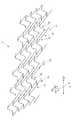
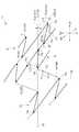
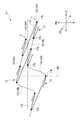
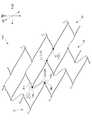
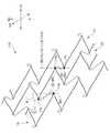
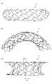
以下、図面を参照して、本発明による高柔軟性ステントの第1実施形態を説明する。まず、図1から図3を参照して、本発明の第1実施形態による高柔軟性ステント11の全体構成を説明する。図1は、無負荷状態の本発明の第1実施形態の高柔軟性ステントの斜視図である。図2は、無負荷状態の本発明の第1実施形態の高柔軟性ステントを仮想的に平面に展開して示す展開図である。図3は、図2に示すステントの部分拡大図である。 Hereinafter, a first embodiment of a highly flexible stent according to the present invention will be described with reference to the drawings. First, the overall configuration of the highly
図1に示すように、ステント11は略円筒形状である。ステント11の周壁は、ワイヤ状の材料で囲まれた合同な形状を有する複数のクローズドセルが周方向に敷き詰められたメッシュパターンの構造を、有している。図2では、ステント11の構造の理解を容易にするために、ステント11は平面に展開した状態で示されている。また、図2では、メッシュパターンの周期性を示すために、仮想的に、実際の展開状態よりもメッシュパターンを繰り返した形で示している。本明細書において、ステント11の周壁とは、ステント11の略円筒構造の円筒の内部と外部とを隔てる部分を意味する。また、セルとは、開口又は隔室ともいい、ステント11のメッシュパターンを形成するワイヤ状の材料で囲まれた部分をいう。 As shown in FIG. 1, the
ステント11は、ステンレス鋼、又はタンタル、プラチナ、金、コバルト、チタン若しくはこれらの合金のような生体適合性を有する材料から形成されている。 The
ステント11は、軸線方向(すなわち中心軸線方向)LDに並んで配置される複数の波線状パターン体としての環状体13と、軸線方向LDに隣り合う環状体13の間に配置されている複数のコイル状要素15と、を備える。図3に示すように、環状体13は、二つの脚部17aを頂部17bで連結した略V字形状の波形要素17を周方向に複数接続して形成される波線状パターンを、有する。 The
詳細には、頂部17bを交互に逆側に配置した状態で、略V字形状の波形要素17は接続される。周方向に隣接する2つの脚部17aにおいては、頂部17bとは反対側の端部17c同士は、連結されて一体化している。 Specifically, the substantially V-shaped
軸線方向LDに対して垂直な径方向RDに視たときに、環状体13の環方向CDは、径方向RDに対して傾斜している。径方向RDに対して環状体13の環方向CDが傾斜する角度θ3は、例えば30度〜60度である。 When viewed in the radial direction RD perpendicular to the axial direction LD, the ring direction CD of the
なお、径方向RDは、軸線方向LDに対して垂直な方向であり、そのため、無数に存在する。図3、図4等において「径方向RDに視たときに、」における径方向RDは、図3、図4等の紙面を貫く方向であり、一方、「径方向RDに対して・・・・傾斜する」における径方向RDは、図3、図4等の紙面に沿う方向である。 The radial direction RD is a direction perpendicular to the axial direction LD, and therefore there are innumerable numbers. In FIG. 3, FIG. 4, etc., the radial direction RD in “when viewed in the radial direction RD” is a direction that penetrates the paper surface of FIG. 3, FIG. 4, etc., while “with respect to the radial direction RD... The radial direction RD in “inclined” is the direction along the paper surface of FIGS. 3 and 4.
本出願人は、本発明の基本的な内容について特許出願:特願2014−165104を行っている。特願2014−165104に記載されている内容は、本発明にも適宜に適用又は援用されることができる。 The applicant has filed a patent application: Japanese Patent Application No. 2014-165104 for the basic contents of the present invention. The contents described in Japanese Patent Application No. 2014-165104 can be appropriately applied or incorporated in the present invention.
各コイル状要素15の両端部は、それぞれ、隣り合う二つの環状体13の対向する側の頂部17bに接続されている。なお、隣り合う環状体13の対向する側の頂部17bの全ては、相互にコイル状要素15によって接続されている。ステント11は、いわゆるクローズドセル構造を有している。すなわち、隣り合う環状体13の一方において波線状パターンに沿って脚部17aによって互いに接続される三つの頂部17bのうちの波線状パターンに沿って隣りに位置する二つの頂部17bは、それぞれコイル状要素15によって、隣り合う環状体13の他方において波線状パターンに沿って脚部17aによって互いに接続される三つの頂部のうちの波線状パターンに沿って隣りに位置する二つの頂部に接続されて、セルを形成する。そして、各環状体13の波線状パターンの全ての頂部17bは、三つのセルに共有される。 Both ends of each coil-shaped
複数のコイル状要素15は、環状体13の環方向CDに沿って等間隔で配置されている。各コイル状要素15は、中心軸線周りに螺旋状に延びている。図3に示すように、環状体13に対して軸線方向LDの一方側に位置する一方のコイル状要素15(15R)の巻き方向(右巻き)と、軸線方向LDの他方側に位置する他方のコイル状要素15(15L)の巻き方向(左巻き)とは、逆である。一方のコイル状要素15Rの長さは、脚部17aの長さよりも長い。他方のコイル状要素15Lの長さは、脚部17aの長さよりも短い。 The plurality of
図4に示すように、波形要素17の頂部17bには、瘤状部19が形成されている。瘤状部19は、軸線方向LDに直線状に延びる延長部分19aと、その先端に形成された略半円形部分(先端部分)19bと、を含む。延長部分19aは、コイル状要素15の幅よりも大きい幅を有している。さらに、波形要素17の頂部17bには、内側周縁部から軸線方向LDに延びるスリット21が、形成されている。このため、二つの脚部17aは、軸線方向LDに概略平行に延びる直線部分を介して、延長部分19aにおけるスリット21が設けられていない領域、及び瘤状部19の略半円形部分19bに接続される。なお、先端部分19bは、略半円形の略半円形部分であることが好ましいが、略半円形でなくてもよい(不図示)。 As shown in FIG. 4, a
各コイル状要素15の両端部には、湾曲部15aが形成されている。各コイル状要素15の両端部は、それぞれ、湾曲部15aを介して、隣り合う二つの環状体13の対向する側の頂部17b(詳細にはその瘤状部19)に接続されている。図4に示すように、コイル状要素15の両端部の湾曲部15aは、円弧形状を有している。コイル状要素15と環状体13の波線状パターンの頂部17bとの接続端におけるコイル状要素15の接線方向は、軸線方向LDに一致する。
コイル状要素15の端部の幅方向中心と環状体13の頂部17bの頂点(幅方向中心)とは、ずれている(一致していない)。コイル状要素15の端部の幅方向の一方の端縁と環状体13の頂部17bの幅方向の端縁とは、一致している。 The center in the width direction of the end of the coiled
ステント11は、以上のような構造を備えることにより、優れた形状追従性や縮径性を実現すると共に、金属疲労によるステントの破損を生じにくくしている。ステント11の環状体13の波形要素17の頂部17bに設けられた瘤状部19は、金属疲労を軽減する効果を奏する。ステント11の環状体13の波形要素17の頂部17bの内側周縁から延びるスリット21は、ステント11の縮径性を向上させる効果を奏する。 By providing the
従来のクローズドセル構造のステントは、構造上、柔軟性に欠けるので、屈曲血管において座屈を生じて血流の阻害を招く危険性があった。また、ステントが局所的に変形すると、その変形の影響がステントの径方向RDだけでなく、軸線方向LDにも伝播され、ステントは局所的に独立して変形できない。これに起因して、ステントは、動脈瘤のような複雑な血管構造に適合できずにステントの周壁と血管壁との間に隙間を生じてしまい、血管の拍動に伴う変形でステントが血管内腔で滑りやすくなって、留置後のステントの移動(マイグレーション)を生じる恐れもあった。 Since the conventional closed cell structure stent lacks flexibility in structure, there is a risk that buckling occurs in a bent blood vessel and blood flow is obstructed. Further, when the stent is locally deformed, the effect of the deformation is propagated not only in the radial direction RD of the stent but also in the axial direction LD, and the stent cannot be locally locally deformed. Due to this, the stent cannot adapt to a complicated vascular structure such as an aneurysm, and a gap is created between the peripheral wall of the stent and the blood vessel wall. There is also a risk that the stent may become slippery in the lumen, causing migration (migration) of the stent after placement.
これに対して、本実施形態のステント11は、展開(拡張)状態から縮径(クリンプ)状態に変形させるとき、環状体13の波線状パターンが折り畳まれるように圧縮した状態になると共に、コイル状要素15がコイルバネのように軸線方向LDに寝て軸線方向LDに引っ張られたような状態になる。ステント11の環状体13の波線状パターンの波形要素17の一つを取り出して考えると、波形要素17は、ステント11の縮径及び拡張の際に、ピンセットの開閉のように変形する。 On the other hand, when the
波形要素17の根本の谷側部分(頂部17bの内側周縁部)にスリット21が設けられていない場合、ステント11を縮径させるときに波形要素17を閉じるように変形させると、脚部17aの中央部は、樽状に外側に膨らんで変形しやすい。波形要素17がこのように樽状に膨らんで変形すると、ステント11を縮径する際に、環状体13において周方向に隣り合う波形要素17の脚部17aの樽状に膨らんだ部分同士は、接触する。 When the
この接触は、ステント11(特にその環状体13)が縮径することを妨げ、縮径率を低くする要因となる。これに対して、本実施形態のステント11では、環状体13の波形要素17の根本部分にスリット21が設けられている。そのため、ステント11を縮径する際に、ステント11は変形して、環状体13において周方向に隣り合う波形要素17の脚部17a同士は、接触しにくくなり、縮径率を高めることができる。 This contact prevents the stent 11 (particularly its annular body 13) from being reduced in diameter, and becomes a factor of reducing the diameter reduction rate. On the other hand, in the
ステント11の環状体13の波形要素17の頂部17bにスリット21が設けられている場合に、頂部17bに設けられた瘤状部19の延長部分19aの長さがスリット21を越える長さを有するように構成することにより、負荷時にスリット21の周辺部においてマルテンサイト相へ相変態する体積比率が高まる。したがって、ステント11が頂部17bを有する波形要素17を備えるように構成されることにより、ステント11の直径の変化に対する拡張力の変化が緩やかで、異なる血管径でも拡張力の変化の少ないステント11を実現することができる。 When the
ステント11のコイル状要素15の両端部に設けられた湾曲部15aは、環状体13との接続部におけるコイル状要素15の変形を一層円滑にさせ、ステント11の縮径性を高める効果を奏する。 The
ステント11を縮径させる際には、コイル状要素15が軸線方向LDに引き伸ばされるように変形する。そのため、ステント11の柔軟性を高めるためには、環状体13の頂部17bとコイル状要素15との接続部分が柔軟となる設計にする必要がある。ステント11では、コイル状要素15の両端部に円弧形状を有する湾曲部15aを設け、湾曲部15aを介して環状体13の頂部17bとコイル状要素15とを接続している。ステント11の縮径時に、湾曲部15aが曲げを受けて変形することにより、コイル状要素15の柔軟な変形を可能にし、縮径性を向上させている。 When the diameter of the
また、コイル状要素15と環状体13の頂部17bとが接続する接続端における湾曲部15aの接線方向が軸線方向LDに一致する構成は、ステント11の縮径及び拡張に伴う変形を容易にすると共に、ステント11の直径の変化に対する拡張力の変化を緩やかにする効果を奏する。 In addition, the configuration in which the tangential direction of the
コイル状要素15は、コイルバネのように変形して、軸線方向LDに伸長することにより、ステント11の縮径に伴う径方向RDの変形を可能にしている。したがって、環状体13とコイル状要素15とが接続する接続端における湾曲部15aの接線方向を軸線方向LDに一致させることにより、コイル状要素15の軸線方向LDへの変形特性を効果的に発揮できるようになる。コイル状要素15が軸線方向LDに円滑に変形できるようになる結果、ステント11の縮径及び拡張が容易になる。また、コイル状要素15の軸線方向LDの自然な変形が促されることによって、予期しない変形抵抗が発生することを防ぐことができ、ステント11の直径の変化に対する拡張力の応答が緩やかになる効果を奏する。 The coil-shaped
ステント11は、縮径された状態でカテーテル内に挿入され、プッシャーなどの押出機で押されてカテーテル内を移動し、病変部位に展開される。このとき、押出機により付与される軸線方向LDの力は、ステント11の環状体13及びコイル状要素15の間で相互作用を及ぼしながらステント11の全体に伝達されていく。 The
上記のような構造のステント11は、例えば生体適合性材料を、特に好ましくは超弾性合金から形成されたチューブを、レーザ加工することにより作製される。超弾性合金チューブから作製する場合、コストを低減させるため、2〜3mm程度のチューブを、レーザ加工後、所望する径まで拡張させ、チューブに形状記憶処理を施すことにより、ステント11は作製されることが好ましい。しかしながら、ステント11の作製は、レーザ加工によるものに限定されるものではなく、例えば切削加工など他の方法によって作製することも可能である。 The
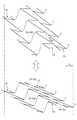
次に、本発明の特徴部分について詳述する。図5は、図3に示すステントにおける各種角度について示す図である。図6は、図5に示すステンドが縮径されたときの状態を示す図である。図7は、ステントの長さの変化を示す説明図である。 Next, the characteristic part of the present invention will be described in detail. FIG. 5 is a diagram showing various angles in the stent shown in FIG. FIG. 6 is a diagram showing a state when the stained shown in FIG. 5 is reduced in diameter. FIG. 7 is an explanatory diagram showing changes in the length of the stent.
図5に示すように、径方向RDに視たときに、コイル状要素15(15R)によって接続されている頂部17b同士(頂部17bを●で示す)を仮想的に結ぶ第1仮想直線L1のうちの一部又は全部の第1仮想直線L1が径方向RDに対して傾斜する角度θ1は、30度以下の第1傾斜角度である。なお、図5〜図13においては、コイル状要素15を破線で示している。第1実施形態においては、第1仮想直線L1は、コイル状要素15(15R)が延びる方向とは一致していない。 As shown in FIG. 5, when viewed in the radial direction RD, a first virtual straight line L1 that virtually connects the tops 17b (the tops 17b are indicated by ●) connected by the coil-shaped element 15 (15R). An angle θ1 at which some or all of the first virtual straight lines L1 are inclined with respect to the radial direction RD is a first inclination angle of 30 degrees or less. 5 to 13, the coil-shaped
環状体13に対して軸線方向LDの一方側に位置する一方の第1仮想直線L1は、第1傾斜角度θ1で傾斜する小傾斜第1仮想直線L11であり、軸線方向LDの他方側に位置する他方の第1仮想直線L1は、大傾斜第1仮想直線L12である。大傾斜第1仮想直線L12は、第1仮想直線L1のうちの小傾斜第1仮想直線L11以外の直線である。
小傾斜第1仮想直線L11と大傾斜第1仮想直線12とは、軸線方向LDに交互に配列している。One first imaginary straight line L1 located on one side in the axial direction LD with respect to the
The small inclined first virtual straight lines L11 and the large inclined first virtual straight lines 12 are arranged alternately in the axial direction LD.
径方向RDに視たときに、脚部17aの両端部(両端部を●で示す)を仮想的に結ぶ第2仮想直線L2のうちの一部又は全部の第2仮想直線L2が軸線方向LDに対して傾斜する角度θ2は、30度以下の第2傾斜角度である。脚部17aの端部は、頂部17b、又は、頂部17bとは反対側の端部17cである。 When viewed in the radial direction RD, some or all of the second virtual straight lines L2 of the second virtual straight line L2 that virtually connects both ends of the
1つの略V字形状の波形要素17に着目した場合に、2つの脚部17a,17aを連結する頂部17bは、周方向において、2つの脚部17a,17aにおける、2つの脚部17a,17aを連結する頂部17bとは反対側の端部同士の間に位置しない。本実施形態においては、反対側の端部の一方は、別の頂部17bであり、他方は、反対側の端部17cである。言い換えると、1つの略V字形状の波形要素17に着目した場合に、周方向において、2つの脚部17a,17aを連結する頂部17b、別の頂部17b、反対側の端部17cの順に配置している。 When focusing on one substantially V-shaped
第2傾斜角度θ2で傾斜する小傾斜第2仮想直線L2は、コイル状要素15によって接続されて軸線方向LDに隣接している。隣接している小傾斜第2仮想直線L2のうちの一方の小傾斜第2仮想直線L21が軸線方向LDに対して傾斜する角度θ21と、他方の小傾斜第2仮想直線L22が軸線方向LDに対して傾斜する角度θ22とは、異なる。一方の小傾斜第2仮想直線L21が軸線方向LDに対して傾斜する角度θ21は、10度未満であり、他方の小傾斜第2仮想直線L22が軸線方向LDに対して傾斜する角度θ22は、10度以上30度以下である。
一方の小傾斜第2仮想直線L21と他方の小傾斜第2仮想直線L22とは、軸線方向LDに交互に配列している。The small inclined second virtual straight line L2 inclined at the second inclination angle θ2 is connected by the coiled
One small inclination second virtual straight line L21 and the other small inclination second virtual straight line L22 are arranged alternately in the axial direction LD.
次に、「軸線方向LDに対して垂直な径方向RDに視たときに、環状体13の環方向CDは径方向RDに対して傾斜している」構成による作用効果について説明する。まず、径方向RDに視たときに環状体13の環方向CDが径方向RDに沿っている(径方向RDに対して傾斜していない)構造のステントについて説明する。 Next, the function and effect of the configuration “when viewed in the radial direction RD perpendicular to the axial direction LD, the ring direction CD of the
環状体13の環方向CDが径方向RDに対して傾斜していない構造のステントは、頭蓋内の屈曲の強い血管においては、ステントの断面の中心軸がズレやすい。
これに対し、本実施形態のステント11では、波線状パターンを有する環状体13が容易に周方向に変形できるので、ステント11は、径方向RDへの収縮や拡張に柔軟に対応することができる。また、隣り合う環状体13,13を接続するコイル状要素15は、中心軸線周りに螺旋状に延びており、コイルバネのように変形する。そのため、ステント11が屈曲された際に、屈曲部の外側でコイル状要素15が伸長すると共に、屈曲部の内側でコイル状要素15が収縮する。これにより、ステント11の全体として、軸線方向LDの柔軟な曲げ変形を可能にしている。In a stent having a structure in which the annular direction CD of the
On the other hand, in the
さらに、ステント11に局所的に与えられた外力や変形は、波線状パターンの環状体13によって径方向RDに伝達されると共に、コイル状要素15によって周方向に伝達される。そのため、環状体13及びコイル状要素15は、各部位でほぼ独立して変形することが可能となる。これにより、ステント11は、脳動脈瘤のような特殊な血管の病変部位に適用された場合でも、病変部位の血管構造に適合して留置され得る。例えば、脳動脈瘤の部位にステント11を留置する場合、波線状パターンの環状体13を瘤のネック部分に配置する。これにより、環状体13が径方向RDに拡張して瘤の空間内にせり出し、この部位に安定してステント11を留めることができる。 Further, the external force or deformation locally applied to the
さらに、コイル状要素15は、瘤のネック部の周辺の血管壁に血管壁の形状に沿って接触し、アンカーのような役割を果たす。そのため、ステント11が移動するリスクも軽減される。さらに、ステント11は、クローズドセル構造を有しているので、屈曲部位に適用された場合でも、ステント11のストラットがフレア状に外側に突出して血管壁を損傷したり、ステント11のストラットが血流疎外を発生させるリスクを軽減させることができる。 Furthermore, the coiled
また、ステント11が左巻きに捻れを受けた場合、一方のコイル状要素15がバネの素線断面に対してその垂直方向に引っ張られるように、力が働く。そのため、素線は、その円周方向に巻き付くように変形し、径方向RDに縮径する挙動を示す。しかし、他方のコイル状要素15は、バネの素線断面に対してその垂直方向に圧縮されるように力が働く。そのため、その素線は、その円周方向に引き離されるような変形を起こし、結果的に径方向RDに外径が拡大する挙動を示す。その結果、各ユニットにおける一方のコイル状要素15,他方のコイル状要素15の変形が互いに相殺されるため、ステント11の全体におけるコイル状要素15の径方向RDの変形量は抑制される。 Further, when the
一方、ステント11が右巻きに捻れを受けた場合、他方のコイル状要素15がバネの素線断面に対してその垂直方向に引っ張られるように、力が働く。そのため、素線は、その円周方向に巻き付くように変形し、径方向RDに縮径する挙動を示す。しかし、一方のコイル状要素15は、バネの素線断面に対してその垂直方向に圧縮されるように、力が働く。そのため、その素線は、その円周方向に引き離されるような変形を起こし、結果的に径方向RDに外径が拡大する挙動を示す。その結果、一方のコイル状要素15の変形と,他方のコイル状要素15の変形とが互いに相殺されるため、ステント11の全体におけるコイル状要素15の径方向RDの変形量が抑制される。
このように、互いに巻き方向が逆であるコイル状要素15R,15Lを導入することで、左右の捻り変形に対し、径方向RDへの変形量の差を軽減することができる。On the other hand, when the
In this way, by introducing the coil-shaped
ステントの材料は、材料自体の剛性が高く且つ生体適合性が高い材料が好ましい。このような材料としては、チタン、ニッケル、ステンレス鋼、白金、金、銀、銅、鉄、クロム、コバルト、アルミニウム、モリブデン、マンガン、タンタル、タングステン、ニオブ、マグネシウム及びカルシウム又はこれらを含む合金が挙げられる。また、このような材料としては、PE、PP等のポリオレフィン、ポリアミド、ポリ塩化ビニル、ポリフェニレンスルフィド、ポリカーボネイト、ポリエーテル、ポリメチルメタクリレート等の合成樹脂材料を用いることもできる。さらに、このような材料としては、ポリ乳酸(PLA)、ポリヒドロキシブチレート(PHB)、ポリグリコール酸(PGA)、ポリεカプロラクトン等の生分解性樹脂(生分解性ポリマー)を用いることもできる。 The material of the stent is preferably a material having high rigidity itself and high biocompatibility. Such materials include titanium, nickel, stainless steel, platinum, gold, silver, copper, iron, chromium, cobalt, aluminum, molybdenum, manganese, tantalum, tungsten, niobium, magnesium and calcium or alloys containing these. To be As such a material, a synthetic resin material such as polyolefin such as PE or PP, polyamide, polyvinyl chloride, polyphenylene sulfide, polycarbonate, polyether, polymethylmethacrylate, or the like can be used. Furthermore, as such a material, a biodegradable resin (biodegradable polymer) such as polylactic acid (PLA), polyhydroxybutyrate (PHB), polyglycolic acid (PGA), and poly ε-caprolactone can also be used. ..
ステントは、薬剤を含んでいてもよい。ここで、ステントが薬剤を含むとは、薬剤が溶出し得るように、ステントが薬剤を放出可能に担持していることをいう。薬剤は、限定されないが、例えば、生理活性物質を用いることができる。 The stent may include a drug. Here, that the stent contains a drug means that the stent carries the drug releasably so that the drug can be eluted. Although the drug is not limited, for example, a physiologically active substance can be used.
薬剤をステントに含ませるには、例えば、ステントの表面を薬剤で被覆すればよい。この際、ステントの表面を薬剤で直接被覆してもよいし、薬剤をポリマー中に含ませ、該ポリマーを用いてステントを被覆してもよい。また、ステントに薬剤を貯蔵するための溝や孔部などをリザーバーとして設け、その中に薬剤や、薬剤とポリマーとを混合したものを貯蔵してもよい。貯蔵するためのリザーバーは、例えば特表2009−524501号公報に記載されている。 In order to include the drug in the stent, for example, the surface of the stent may be coated with the drug. At this time, the surface of the stent may be directly coated with the drug, or the drug may be contained in a polymer and the stent may be coated with the polymer. Further, a groove, a hole or the like for storing the drug may be provided in the stent as a reservoir, and the drug or a mixture of the drug and the polymer may be stored therein. The reservoir for storing is described in, for example, Japanese Patent Publication No. 2009-524501.
ステントの表面には、ダイヤモンドライクカーボン(Diamond Like Carbon)層(DLC層)を被膜させることができる。DLC層は、フッ素を含むDLC層(F−DLC層)であってもよい。その場合、抗血栓性及び生体適合性に優れたステントとなる。 The surface of the stent can be coated with a diamond-like carbon layer (DLC layer). The DLC layer may be a DLC layer containing fluorine (F-DLC layer). In that case, the stent has excellent antithrombogenicity and biocompatibility.
次に、ステント11の使用方法を説明する。患者の血管内にカテーテルが挿入され、カテーテルを病変部位まで到達させる。次に、ステント11は、縮径(クリンプ)されてカテーテル内に配置される。ステント11は、環状体13の波線状パターン、環状体13の頂部17bに形成されたスリット21、コイル状要素15の湾曲部15a、接続端における湾曲部15aの接線方向が軸線方向LDに一致する構成の複合的及び相乗的効果により、縮径性が高められている。そのため、従来のステントと比較してより細いカテーテル内にステント11を挿入することを容易にし、より細い血管へのステント11の適用を可能にする。 Next, a method of using the
次に、プッシャーなどの押出機を用いてカテーテルの内腔に沿って縮径した状態のステントを押し、病変部位でカテーテルの先端からステント11を押し出して展開させる。ステント11は、複数の環状体13をコイル状要素15によって接続した構成、コイル状要素15の湾曲部15a、接続端における湾曲部15aの接線方向が軸線方向LDに一致する構成の複合的及び相乗的効果により、輸送時の柔軟性が高められている、そのため、ステント11は、カテーテルが蛇行した血管内に挿入されている場合でも、カテーテルに沿って柔軟に変形し、病変部位へステント11を輸送することが容易である。 Next, an extruder such as a pusher is used to push the reduced diameter stent along the inner lumen of the catheter, and the
第1実施形態のステント11によれば、例えば以下の効果が奏される。
第1実施形態においては、径方向RDに視たときに、コイル状要素15によって接続されている頂部17b同士を仮想的に結ぶ第1仮想直線L1のうちの一部又は全部の第1仮想直線L1が径方向RDに対して傾斜する角度θ1は、30度以下の第1傾斜角度である。つまり、第1仮想直線L1は、軸線方向LDに対して大きく傾いて、径方向RDに沿った状態となっている。According to the
In the first embodiment, when viewed in the radial direction RD, some or all of the first virtual straight lines L1 that virtually connect the tops 17b connected by the coil-shaped
仮に、第1仮想直線L1が径方向RDに対して傾斜する角度θ1が大きい場合、ステントが縮径すると、コイル状要素15は軸線方向LDに沿って延びるように配置される。その場合、ステントは、コイル状要素15及び波形要素17の幾何学的関係を維持した状態で、全体が軸線方向LDに沿って延びるように変形して、伸展する。その後、ステントがカテーテルから押し出されて展開されると、ステントは短縮され、大きなショートニングが発生しやすい。 If the angle θ1 at which the first virtual straight line L1 is inclined with respect to the radial direction RD is large, and the diameter of the stent is reduced, the coiled
これに対し、第1実施形態のステント11においては、図6及び図7に示すように、ステント11が縮径しても、コイル状要素15は、軸線方向LDよりも径方向RDに沿って延びようとする。そのため、ステント11は、軸線方向LDに沿って伸展しにくい。なお、図7における△Lは、展開時と縮径時とにおけるステント11の長さの違い、つまり、ステント11の伸展長さ(短縮長さ)を示す。従って、ステント11がカテーテルから押し出されて展開されても、ステント11は短縮されにくく、大きなショートニングは発生しにくい。
また、コイル状要素15が径方向RDに沿って延びることになるため、ステント11は曲げ変形しやすくなり、屈曲性が改善される。On the other hand, in the
Moreover, since the coiled
また、第1実施形態のステント11においては、径方向RDに視たときに、脚部17aの両端部を仮想的に結ぶ第2仮想直線L2のうちの一部又は全部の第2仮想直線L2が軸線方向LDに対して傾斜する角度θ2は、30度以下の第2傾斜角度である。その場合、波形要素17は、径方向RDに沿った状態となりやすく、軸線方向LDに沿って延びにくい。そのため、ステントは、軸線方向LDに沿って伸展しにくい。従って、ステントは短縮されにくく、大きなショートニングは発生しにくい。 In addition, in the
波形要素17は、径方向RDに沿った状態となりやすいため、波形要素17における脚部17aの端部が径方向RDに移動しやすい。従って、ステントの縮径が容易となり、ステント11の曲げ変形と径方向RDへの変形が同時に起こりそうになったときに、ステント11は柔軟に変形することができる。
更に、第1仮想直線L1が径方向RDに対して傾斜する角度θ1を小さく設計しやすい。従って、大きなショートニングが発生しにくいという効果を、一層奏しやすくなる。
なお、本実施形態のステントは、留置型及び回収型の両方のステントとして利用可能であるが、留置型として利用する方が好適である。Since the
Further, it is easy to design the angle θ1 at which the first virtual straight line L1 is inclined with respect to the radial direction RD to be small. Therefore, the effect that large shortening is unlikely to occur is more easily exhibited.
The stent of this embodiment can be used as both an indwelling type and a retrieving type, but it is more preferable to use it as an indwelling type.
ステント11は、環状体13の頂部17bに瘤状部19を設ける構成により、金属疲労の発生を抑制することができ、留置ミスによるステント11の縮径及び拡張の繰り返し、血流や血管壁の拍動によるステント11の繰り返し変形などによるステント11の破損を抑制することができる。 The
加えて、ステント11は、環状体13の頂部17bにスリット21を設けることによりクリンプ時に変形部においてマルテンサイト相に相変態する領域を増加させる構成と、コイル状要素15の湾曲部15a、接続端における湾曲部15aの接線方向が軸線方向LDに一致する構成との複合的及び相乗的な効果により、柔軟性が向上すると共に、除荷過程においてステント11の直径の変化に対する拡張力の変化が緩やかになる。この結果、ステント11の形状追従性が向上されると共に、テーパー状の血管のように局所的に血管径が変化する部位においても、血管に過度な負荷を与えることなくステント11を留置することが可能となる。 In addition, the
次に、本発明のステントの他の実施形態について説明する。他の実施形態について特に説明しない点については、第1実施形態についての説明が適宜援用される。他の実施形態においても、第1実施形態と同様の効果を奏する。 Next, another embodiment of the stent of the present invention will be described. For the points that are not particularly described in the other embodiments, the description in the first embodiment is appropriately incorporated. Also in the other embodiments, the same effect as that of the first embodiment is obtained.
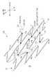
図8は、本発明の第2実施形態の高柔軟性ステントを仮想的に平面に展開して示す展開図(図5対応図)である。図9は、本発明の第3実施形態の高柔軟性ステントを仮想的に平面に展開して示す展開図(図5対応図)である。図10は、本発明の第4実施形態の高柔軟性ステントを仮想的に平面に展開して示す展開図(図5対応図)である。図11は、本発明の第5実施形態の高柔軟性ステントを仮想的に平面に展開して示す展開図(図5対応図)である。図12は、本発明の第6実施形態の高柔軟性ステントを仮想的に平面に展開して示す展開図(図5対応図)である。図13は、本発明の第7実施形態の高柔軟性ステントを仮想的に平面に展開して示す展開図(図5対応図)である。 FIG. 8 is a development view (corresponding to FIG. 5) showing the highly flexible stent of the second embodiment of the present invention virtually expanded on a plane. FIG. 9 is a development view (corresponding to FIG. 5) in which the highly flexible stent of the third embodiment of the present invention is virtually expanded on a plane. FIG. 10 is a development view (corresponding to FIG. 5) in which the highly flexible stent of the fourth embodiment of the present invention is virtually expanded on a flat surface. FIG. 11 is a development view (corresponding to FIG. 5) in which the highly flexible stent of the fifth embodiment of the present invention is virtually expanded on a plane. FIG. 12 is a development view (corresponding to FIG. 5) showing the highly flexible stent of the sixth embodiment of the present invention by virtually expanding it on a plane. FIG. 13 is a development view (corresponding to FIG. 5) showing the highly flexible stent of the seventh embodiment of the present invention by virtually expanding it on a plane.
図8に示すように、第2実施形態のステント11Aにおいては、一方の第1仮想直線L1は、小傾斜第1仮想直線L11であり、他方の第1仮想直線L1は、大傾斜第1仮想直線L12である。小傾斜第1仮想直線L11と大傾斜第1仮想直線L12とは、軸線方向LDに交互に配列している。径方向RDに視たときに、脚部17aの両端部を仮想的に結ぶ第2仮想直線L2のうちの全部の第2仮想直線L2が軸線方向LDに対して傾斜する角度θ2は、30度超である。 As shown in FIG. 8, in the
図9に示すように、第3実施形態のステント11Bにおいては、一方及び他方の第1仮想直線L1の両方が、小傾斜第1仮想直線L11である。その他の構成は、第2実施形態と同様である。
第3実施形態のステント11Bによれば、第2実施形態と比べて、より多くのコイル状要素15が径方向RDに沿って延びることになるため、屈曲性が更に改善される。As shown in FIG. 9, in the
According to the
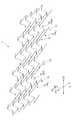
図10に示すように、第4実施形態のステント11Cにおいては、一方の第1仮想直線L1である小傾斜第1仮想直線L11は、径方向RDを交差するように傾斜している。言い換えると、軸線方向LDにおいて、小傾斜第1仮想直線L11に対応するコイル状要素15の両端部に接続される波形要素17同士は、重なっている(入り込んでいる)。なお、図8に示す第2実施形態においては、軸線方向LDにおいて、小傾斜第1仮想直線L11に対応するコイル状要素15の両端部に接続される波形要素17同士は、重なっておらず(入り込んでおらず)、軸線方向LDの外側に配置している。 As shown in FIG. 10, in the
第4実施形態のステント11Cは、前述の構成を有しているため、ステントの表面積を大きく確保しながら、柔軟に曲がると共に左右の捻りに対しても柔軟に応答するステントを実現することができる。 Since the
図11に示すように、第5実施形態のステント11Dにおいては、一方の第1仮想直線L1である小傾斜第1仮想直線L11だけでなく、他方の第1仮想直線L1である小傾斜第1仮想直線L11も、径方向RDを交差するように傾斜している。軸線方向LDにおいて、他方の第1仮想直線L1である小傾斜第1仮想直線L11に対応するコイル状要素15の両端部に接続される波形要素17同士も、重なっている(入り込んでいる)。その他の構成は、第4実施形態と同様である。第5実施形態のステント11Dも、第4実施形態と同等以上の効果を奏する。 As shown in FIG. 11, in the
図12に示すように、第6実施形態のステント11Eは、第4実施形態のステント11Cにおけるコイル状要素15と、第1実施形態のステント11における波形要素17とを組み合わせた実施形態である。つまり、第6実施形態のステント11Eにおいては、第4実施形態と同様に、一方の第1仮想直線L1である小傾斜第1仮想直線L11は、径方向RDを交差するように傾斜している。軸線方向LDにおいて、小傾斜第1仮想直線L11に対応するコイル状要素15の両端部に接続される波形要素17同士は、重なっている(入り込んでいる)。また、第1実施形態と同様に、径方向RDに視たときに、脚部17aの両端部を仮想的に結ぶ第2仮想直線L2のうちの一部又は全部の第2仮想直線L2が軸線方向LDに対して傾斜する角度θ2は、30度以下の第2傾斜角度である。
第6実施形態のステント11Eによれば、第4実施形態の効果と第1実施形態の効果とを併せて奏することができる。As shown in FIG. 12, the
According to the
図13に示すように、第7実施形態のステント11Fは、第5実施形態のステント11Dにおけるコイル状要素15と、第1実施形態のステント11における波形要素17とを組み合わせた実施形態である。つまり、第7実施形態のステント11Fにおいては、第5実施形態と同様に、一方の第1仮想直線L1である小傾斜第1仮想直線L11だけでなく、他方の第1仮想直線L1である小傾斜第1仮想直線L11も、径方向RDを交差するように傾斜している。軸線方向LDにおいて、他方の第1仮想直線L1である小傾斜第1仮想直線L11に対応するコイル状要素15の両端部に接続される波形要素17同士も、重なっている(入り込んでいる)。また、第1実施形態と同様に、径方向RDに視たときに、脚部17aの両端部を仮想的に結ぶ第2仮想直線L2のうちの一部又は全部の第2仮想直線L2が軸線方向LDに対して傾斜する角度θ2は、30度以下の第2傾斜角度である。
第7実施形態のステント11Fによれば、第5実施形態の効果と第1実施形態の効果とを併せて奏することができる。As shown in FIG. 13, the
According to the
前述の実施形態においては、波線状パターン体13は環状体を形成している。一方、本発明においては、周方向に非連続であり且つ環状体を形成しない波線状パターン体13を採用できる。環状体を形成しない波線状パターン体13は、環状体を形成する波線状パターン体と比べて、波線状パターン体を構成するストラット(脚部17a)が1本又は複数本抜けた形状を有する。抜くストラットの本数は、ステント11の形状が実現可能な範囲において、適宜に1本又は複数本を設定できる。 In the above-described embodiment, the wavy
また、環方向CDに隣接するコイル状要素15を繋ぐように、環方向CDに延びる追加ストラットを設けることができる。なお、追加ストラットの形状、設けられる位置、個数などは特に制限されない。 Further, additional struts extending in the ring direction CD may be provided so as to connect the
一方のコイル状要素15Rに着目した場合に、隣り合う一方のコイル状要素15Rを異形にすることができ、また、隣り合う他方のコイル状要素15Lを異形にすることができる。 When paying attention to one coil-shaped
図14は、コイル状要素15の各種変形例を示す展開図である。図14に示すように、コイル状要素15−1は、図3に示すコイル状要素15と比べて屈曲の程度(曲率)が大きくなっている。コイル状要素15−2は、コイル状要素15−1と比べて更に屈曲の程度(曲率)が大きくなっている。コイル状要素15−3は、環方向CDと直交する方向にも突出する曲線状を、有している。コイル状要素15−4は、4個の変曲点を有する曲線状である。
なお、図14においては、第1仮想直線L1が径方向RDに対して傾斜する角度θ1は、30度以下の第1傾斜角度とはなっていない。FIG. 14 is a development view showing various modifications of the coiled
In FIG. 14, the angle θ1 at which the first virtual straight line L1 is inclined with respect to the radial direction RD is not the first inclination angle of 30 degrees or less.
図14に示すコイル状要素15の形状に関する各種変形例は、波形要素17の脚部17aの形状に関する変形に適宜に適用又は援用されることができる。 Various modifications regarding the shape of the coiled
図15は、コイル状要素15と環状体13の頂部17bとの接続部の形状の変形例を示す図(図4対応図)である。図15に示すように、コイル状要素15の端部の幅方向中心と環状体13の頂部17bの頂点(幅方向中心)とは、一致している。コイル状要素15の端部の幅方向の一方の端縁と環状体13の頂部17bの幅方向の端縁とは、ずれている(一致していない)。 FIG. 15 is a view (corresponding to FIG. 4) showing a modified example of the shape of the connecting portion between the coil-shaped
一部のコイル状要素15を、他のコイル状要素15及び環状体13(波形要素17)よりも細くすることができる。図16は、一部のコイル状要素の太さを細くした第1変形例を示す展開図(図2対応図)である。図17は、一部のコイル状要素の太さを細くした第2変形例を示す展開図(図2対応図)である。図18は、一部のコイル状要素の太さを細くした第3変形例を示す展開図(図2対応図)である。図19は、一部のコイル状要素の太さを細くした第4変形例を示す展開図(図2対応図)である。 Some
図16に示すように、第1変形例は、図2に示す例と比べて、全ての一方(右巻き)のコイル状要素15(15R)が細いが、全ての他方(左巻き)のコイル状要素15(15L)及び環状体13が細くないように、構成されている。
図17に示すように、第2変形例は、図16に示す第1変形例と比べて、軸線方向LD方向に1列おきに一方(右巻き)のコイル状要素15Rが細いが、他のコイル状要素15及び環状体13が細くないように、構成されている。As shown in FIG. 16, in the first modified example, all the one (right-handed) coil-shaped elements 15 (15R) are thinner than the example shown in FIG. 2, but all the other (left-handed) coil-shaped elements are formed. The element 15 (15L) and the
As shown in FIG. 17, in the second modification, one (right-handed) coil-shaped
図18に示すように、第3変形例は、図17に示す第2変形例と比べて、細いコイル状要素15Rの位置が軸線方向LDにずれて構成されている。
図19に示すように、第4変形例は、図16に示す第1変形例と比べて、軸線方向LDの両端部に位置する一方(右巻き)のコイル状要素15Rは細くなっておらず、その他の一方(右巻き)のコイル状要素15Rが細く、構成されている。As shown in FIG. 18, the third modified example is configured such that the position of the thin coil-shaped
As shown in FIG. 19, in the fourth modified example, one (right-handed) coil-shaped
図16〜図19に示す第1変形例〜第4変形例のように一部のコイル状要素15が細く構成されることにより、ステント11は、径方向RDの剛性を維持したまま、曲げ剛性を高くすることができる(曲げ柔軟性を高めることができる)。
なお、前述の第1変形例〜第4変形例では、一方(右巻き)のコイル状要素15(15R)を細くした例について説明したが、これに制限されない。他方(左巻き)のコイル状要素15(15L)を細くすることもできる。この場合においても、一方(右巻き)のコイル状要素15(15R)を細くした場合と同様の効果が得られる。As part of the coil-shaped
In addition, in the above-mentioned first to fourth modified examples, an example in which one (right-handed) coil-shaped element 15 (15R) is made thin has been described, but the present invention is not limited to this. The other (left-handed) coiled element 15 (15L) can also be made thinner. Also in this case, the same effect as when the one (right-handed) coil-shaped element 15 (15R) is made thin can be obtained.
コイル状要素15を挟んで軸線方向LDに隣り合う脚部17aの長さ〔(a)、(b)〕を異ならせることができる。図20は、コイル状要素を挟んで軸線方向に隣り合う脚部における、軸線方向の長さの関係を示す図であり、(A)は長さが等しい場合を示し、(B)は長さが異なる場合を示す。図20(A)に示す例では、コイル状要素15を挟んで軸線方向LDに隣り合う脚部17aの長さは、実質的に等しくなっている〔(a)=(b)〕。これに対して、図20(B)に示す例では、コイル状要素15を挟んで軸線方向LDに隣り合う脚部17aの長さは、互いに異なっている。具体的には、(a)>(b)の関係となっている。 The lengths [(a) and (b)] of the
図21は、ステントを軸線方向に沿って曲げた状態を示す図であり、(A)は引っ張られている側から視た図、(B)は無負荷の側から視た図、(C)は圧縮されている側から視た図である。図21に示すように、ステント11を軸線方向LDに沿って大きく曲げた場合、(C)に示す圧縮されている側において、環状体13と、環状体13に対向するコイル状要素15とは接触しやすい。両者が接触すると、座屈が生じやすい。
一方、脚部17aの長さが短い(b)場合、図21(C)に示すように、環状体13とコイル状要素15とが接触するまでの距離(c)を長くすることができる。そのため、ステント11を軸線方向LDに沿って大きく曲げた場合において、座屈を抑制できる。FIG. 21 is a view showing a state in which the stent is bent along the axial direction, (A) is a view seen from a pulled side, (B) is a view seen from an unloaded side, (C). Is a view seen from the compressed side. As shown in FIG. 21, when the
On the other hand, when the length of the
ステント11の軸線方向LDの端部の構造を異ならせることができる。図22は、軸線方向の端部の構造が異なる変形例を示す展開図である。図22に示すように、ステント11の軸線方向LDの端部(図22の下方側に位置する端部)において、ストラットの端部の位置をほぼ揃えてもよい。この場合、ステント11の縮径(クリンプ)時にステント11を押しやすい。また、ステント11の留置時に、ストラットの端部の位置がほぼ揃っているため、安全性が高い。 The structure of the end portion of the
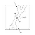
ステント11に、視認性が高い(放射線不透過性が高い)部材を設けることができる。図23は、視認性向上に係る第1変形例を示す図である。図24は、視認性向上に係る第2変形例を示す図である。図23に示すように、各種ストラット(コイル状要素15、環状体13)には、孔25が設けられており、この孔25には、視認性が高い部材23aが埋め込まれている。また、図24に示すように、各種ストラット(コイル状要素15、環状体13)には、孔25が設けられており、この孔25には、視認性が高いワイヤ状部材23bが通されている。ワイヤ状部材23bは、更に各種ストラット(コイル状要素15、環状体13)に巻き付けられる。視認性が高い部材23a、23bの材料は、金属でもよく、合成樹脂でもよい。 The
ステント11に、視認性が高い(放射線不透過性が高い)部材23a、23bが設けられる場合、例えば、ステント11が広がっている状態を容易に視認することができる。
視認性が高い部材23a、23bのための孔25が設けられる各種ストラット(コイル状要素15、環状体13)としては、実質的に曲がらないストラットや実質的に変形しないストラットが好ましい。実質的に曲がらないストラットや実質的に変形しないストラットとしては、長さが短い他方のコイル状要素15Lが挙げられる。また、視認性が高い部材23a、23bのための孔25が設けられる部分は、ストラットのうち実質的に変形しない部分が好ましい。その理由は次の通りである。孔25の周辺のストラットの部分に応力が加わりにくく、孔25の周辺のストラットの部分が破損しにくい。また、孔25に嵌め込まれている/通されている視認性が高い部材23a/23bが破損したり、孔25から脱落しにくい。When the
As the various struts (the coil-shaped
以上、図示されている実施形態を参照して、本発明によるステントを説明したが、本発明は、図示されている実施形態に限定されるものではない。例えば、コイル状要素15の螺旋方向は、左巻きでもよく、右巻きでもよい。 Although the stent according to the present invention has been described above with reference to the illustrated embodiments, the present invention is not limited to the illustrated embodiments. For example, the spiral direction of the coiled
角度θ1を規定する第1仮想直線L1は、径方向RDに対してステントの押し出し方向に傾斜していてもよく、押し出し方向とは反対方向のステントの引き戻し方向に傾斜していてもよい。角度θ2を規定する第2仮想直線は、軸線方向LDに対して左右いずれの方向に傾斜していてもよい。 The first imaginary straight line L1 that defines the angle θ1 may be inclined in the stent pushing direction with respect to the radial direction RD, or may be inclined in the stent pullback direction opposite to the pushing direction. The second virtual straight line defining the angle θ2 may be inclined in either the left or right direction with respect to the axial direction LD.
前記実施形態においては、第2仮想直線L2が軸線方向LDに対して傾斜する第2傾斜角度θ2、及び他方の小傾斜第2仮想直線L22が軸線方向LDに対して傾斜する角度θ22が30度以下である形態が主に示されているが、これに制限されない。第2傾斜角度θ2を有する第2仮想直線L2に対応する脚部17a、及び傾斜角度θ22を有する他方の小傾斜第2仮想直線L22に対応する脚部17aが、それに隣接する脚部17aに過度に強く接触しなければ、第2傾斜角度θ2及び角度θ22は、30度を超えていてもよい。
本発明のステントは、脳血管、下肢の血管、その他の血管に適用されることができる。In the embodiment, the second tilt angle θ2 at which the second virtual straight line L2 is tilted with respect to the axial direction LD and the angle θ22 at which the other small tilt second virtual straight line L22 is tilted with respect to the axial direction LD are 30 degrees. The following forms are mainly shown, but are not limited thereto. The
The stent of the present invention can be applied to cerebral blood vessels, blood vessels of the lower limbs, and other blood vessels.
11,11A,11B,11C,11D,11E,11F ステント(高柔軟性ステント)
13 環状体(波線状パターン体)
15 コイル状要素
15L 他方のコイル状要素
15R 一方のコイル状要素
17 波形要素
17a 脚部
17b 頂部
17c 反対側の端部
CD 環方向
LD 軸線方向
L1 第1仮想直線
L11 小傾斜第1仮想直線
L12 大傾斜第1仮想直線
L2 第2仮想直線
L21 一方の小傾斜第2仮想直線
L22 他方の小傾斜第2仮想直線
RD 径方向
θ1 第1傾斜角度
θ2 第2傾斜角度11, 11A, 11B, 11C, 11D, 11E, 11F Stent (highly flexible stent)
13 annular body (wavy line pattern body)
15 coil-shaped
Claims (3)
Translated fromJapanese軸線方向に対して垂直な径方向に視たときに、前記波線状パターン体の環方向は、前記径方向に対して傾斜しており、
前記径方向に視たときに、前記コイル状要素によって接続されている前記頂部同士を仮想的に結ぶ基準直線は、前記径方向に対して傾斜する角度θ1が30度以下の第1基準直線と、前記径方向に対して傾斜する鋭角の角度の絶対値が前記第1基準直線の前記角度θ1よりも大きい角度で前記径方向に対して傾斜する第2基準直線とを含む、
高柔軟性ステント。A plurality of wavy line pattern bodies having a wavy line pattern and arranged side by side in the axial direction, and a plurality of coil-shaped elements arranged between the adjacent wavy line pattern bodies and spirally extending around the axis line. A highly flexible stent in which all of the apexes on the opposite sides of the wavy line patterns of the adjacent wavy line pattern bodies are mutually connected by the coiled element,
When viewed in a radial direction perpendicular to the axial direction, the ring direction of the wavy pattern body is inclined with respect to the radial direction,
When viewed in the radial direction, the reference straight line that virtually connects the tops connected by the coiled element is a first reference straight line having an angle θ1 of 30 degrees or less with respect to the radial direction. A second reference straight line that is inclined with respect to the radial direction atan anglewhose absolute value that is inclined with respect to the radial direction is larger than the angle θ1 of the first reference straight line.
Highly flexible stent.
請求項1に記載の高柔軟性ステント。The first reference straight line is located on one side in the axial direction with respect to the wavy line pattern body, and the second reference straight line is located on the other side in the axial direction with respect to the wavy line pattern body.
The highly flexible stent according to claim 1.
請求項1又は2に記載の高柔軟性ステント。By the fact that the winding direction of the one coil-shaped element located on the one side in the axial direction with respect to the wavy line-shaped pattern body and the winding direction of the other coil-shaped element located on the other side in the axial direction are opposite Suppressed the amount of deformation in the radial direction of the stent due to twisting load,
The highly flexible stent according to claim 1 or 2.
Applications Claiming Priority (2)
| Application Number | Priority Date | Filing Date | Title |
|---|---|---|---|
| JP2015072567 | 2015-03-31 | ||
| JP2015072567 | 2015-03-31 |
Publications (2)
| Publication Number | Publication Date |
|---|---|
| JP2016193186A JP2016193186A (en) | 2016-11-17 |
| JP6734097B2true JP6734097B2 (en) | 2020-08-05 |
Family
ID=57004375
Family Applications (1)
| Application Number | Title | Priority Date | Filing Date |
|---|---|---|---|
| JP2016067986AActiveJP6734097B2 (en) | 2015-03-31 | 2016-03-30 | Highly flexible stent |
Country Status (2)
| Country | Link |
|---|---|
| JP (1) | JP6734097B2 (en) |
| WO (1) | WO2016159161A1 (en) |
Family Cites Families (4)
| Publication number | Priority date | Publication date | Assignee | Title |
|---|---|---|---|---|
| JP5523700B2 (en)* | 2005-04-04 | 2014-06-18 | フレキシブル ステンティング ソリューションズ,インク. | Flexible stent |
| US7404823B2 (en)* | 2005-10-31 | 2008-07-29 | Boston Scientific Scimed, Inc. | Stent configurations |
| EP2421470A4 (en)* | 2009-04-24 | 2016-03-30 | Flexible Stenting Solutions Inc | Flexible devices |
| JP5586742B1 (en)* | 2013-06-28 | 2014-09-10 | 株式会社World Medish | High flexibility stent |
- 2016
- 2016-03-30JPJP2016067986Apatent/JP6734097B2/enactiveActive
- 2016-03-30WOPCT/JP2016/060528patent/WO2016159161A1/ennot_activeCeased
Also Published As
| Publication number | Publication date |
|---|---|
| WO2016159161A1 (en) | 2016-10-06 |
| JP2016193186A (en) | 2016-11-17 |
Similar Documents
| Publication | Publication Date | Title |
|---|---|---|
| JP6764960B2 (en) | Stents and Catheter Stent Systems | |
| JP5719327B2 (en) | Helical stent | |
| US6610086B1 (en) | Radially expandable stent IV | |
| JP7097166B2 (en) | Flexible stent | |
| JP2017533806A (en) | Stent prosthesis | |
| JP5586742B1 (en) | High flexibility stent | |
| JP6688125B2 (en) | Highly flexible stent | |
| CN114364351A (en) | bracket | |
| WO2021095675A1 (en) | Stent and method for inspecting same | |
| JP6734097B2 (en) | Highly flexible stent | |
| JP4064724B2 (en) | Stent and stent graft | |
| JP6967571B2 (en) | Stent | |
| JP4835113B2 (en) | Stent | |
| US20230225889A1 (en) | Stent, stent delivery system, and stent manufacturing method | |
| WO2023237090A1 (en) | Neurovascular stent | |
| JP2009178228A (en) | In vivo indwelling stent and biological organ dilator | |
| JP2019170647A (en) | Stent | |
| HK40004070A (en) | Flexible stent | |
| JP2009513234A (en) | Stent with untwisted shape |
Legal Events
| Date | Code | Title | Description |
|---|---|---|---|
| A621 | Written request for application examination | Free format text:JAPANESE INTERMEDIATE CODE: A621 Effective date:20190228 | |
| A977 | Report on retrieval | Free format text:JAPANESE INTERMEDIATE CODE: A971007 Effective date:20191212 | |
| A131 | Notification of reasons for refusal | Free format text:JAPANESE INTERMEDIATE CODE: A131 Effective date:20191217 | |
| A521 | Request for written amendment filed | Free format text:JAPANESE INTERMEDIATE CODE: A523 Effective date:20200217 | |
| A131 | Notification of reasons for refusal | Free format text:JAPANESE INTERMEDIATE CODE: A131 Effective date:20200331 | |
| A521 | Request for written amendment filed | Free format text:JAPANESE INTERMEDIATE CODE: A523 Effective date:20200528 | |
| TRDD | Decision of grant or rejection written | ||
| A01 | Written decision to grant a patent or to grant a registration (utility model) | Free format text:JAPANESE INTERMEDIATE CODE: A01 Effective date:20200623 | |
| A61 | First payment of annual fees (during grant procedure) | Free format text:JAPANESE INTERMEDIATE CODE: A61 Effective date:20200709 | |
| R150 | Certificate of patent or registration of utility model | Ref document number:6734097 Country of ref document:JP Free format text:JAPANESE INTERMEDIATE CODE: R150 | |
| R350 | Written notification of registration of transfer | Free format text:JAPANESE INTERMEDIATE CODE: R350 | |
| R250 | Receipt of annual fees | Free format text:JAPANESE INTERMEDIATE CODE: R250 | |
| R250 | Receipt of annual fees | Free format text:JAPANESE INTERMEDIATE CODE: R250 | |
| R250 | Receipt of annual fees | Free format text:JAPANESE INTERMEDIATE CODE: R250 |