JP6732741B2 - Method and apparatus for deep-drawing a tray from sheet material - Google Patents
Method and apparatus for deep-drawing a tray from sheet materialDownload PDFInfo
- Publication number
- JP6732741B2 JP6732741B2JP2017520465AJP2017520465AJP6732741B2JP 6732741 B2JP6732741 B2JP 6732741B2JP 2017520465 AJP2017520465 AJP 2017520465AJP 2017520465 AJP2017520465 AJP 2017520465AJP 6732741 B2JP6732741 B2JP 6732741B2
- Authority
- JP
- Japan
- Prior art keywords
- tray
- sheet material
- cavity
- forming
- mold
- Prior art date
- Legal status (The legal status is an assumption and is not a legal conclusion. Google has not performed a legal analysis and makes no representation as to the accuracy of the status listed.)
- Expired - Fee Related
Links
Images


Classifications
- B—PERFORMING OPERATIONS; TRANSPORTING
- B29—WORKING OF PLASTICS; WORKING OF SUBSTANCES IN A PLASTIC STATE IN GENERAL
- B29C—SHAPING OR JOINING OF PLASTICS; SHAPING OF MATERIAL IN A PLASTIC STATE, NOT OTHERWISE PROVIDED FOR; AFTER-TREATMENT OF THE SHAPED PRODUCTS, e.g. REPAIRING
- B29C51/00—Shaping by thermoforming, i.e. shaping sheets or sheet like preforms after heating, e.g. shaping sheets in matched moulds or by deep-drawing; Apparatus therefor
- B29C51/08—Deep drawing or matched-mould forming, i.e. using mechanical means only
- B—PERFORMING OPERATIONS; TRANSPORTING
- B31—MAKING ARTICLES OF PAPER, CARDBOARD OR MATERIAL WORKED IN A MANNER ANALOGOUS TO PAPER; WORKING PAPER, CARDBOARD OR MATERIAL WORKED IN A MANNER ANALOGOUS TO PAPER
- B31B—MAKING CONTAINERS OF PAPER, CARDBOARD OR MATERIAL WORKED IN A MANNER ANALOGOUS TO PAPER
- B31B50/00—Making rigid or semi-rigid containers, e.g. boxes or cartons
- B31B50/26—Folding sheets, blanks or webs
- B31B50/44—Folding sheets, blanks or webs by plungers moving through folding dies
- B—PERFORMING OPERATIONS; TRANSPORTING
- B31—MAKING ARTICLES OF PAPER, CARDBOARD OR MATERIAL WORKED IN A MANNER ANALOGOUS TO PAPER; WORKING PAPER, CARDBOARD OR MATERIAL WORKED IN A MANNER ANALOGOUS TO PAPER
- B31B—MAKING CONTAINERS OF PAPER, CARDBOARD OR MATERIAL WORKED IN A MANNER ANALOGOUS TO PAPER
- B31B50/00—Making rigid or semi-rigid containers, e.g. boxes or cartons
- B31B50/59—Shaping sheet material under pressure
- B—PERFORMING OPERATIONS; TRANSPORTING
- B31—MAKING ARTICLES OF PAPER, CARDBOARD OR MATERIAL WORKED IN A MANNER ANALOGOUS TO PAPER; WORKING PAPER, CARDBOARD OR MATERIAL WORKED IN A MANNER ANALOGOUS TO PAPER
- B31B—MAKING CONTAINERS OF PAPER, CARDBOARD OR MATERIAL WORKED IN A MANNER ANALOGOUS TO PAPER
- B31B70/00—Making flexible containers, e.g. envelopes or bags
- B—PERFORMING OPERATIONS; TRANSPORTING
- B31—MAKING ARTICLES OF PAPER, CARDBOARD OR MATERIAL WORKED IN A MANNER ANALOGOUS TO PAPER; WORKING PAPER, CARDBOARD OR MATERIAL WORKED IN A MANNER ANALOGOUS TO PAPER
- B31F—MECHANICAL WORKING OR DEFORMATION OF PAPER, CARDBOARD OR MATERIAL WORKED IN A MANNER ANALOGOUS TO PAPER
- B31F1/00—Mechanical deformation without removing material, e.g. in combination with laminating
- B31F1/0077—Shaping by methods analogous to moulding, e.g. deep drawing techniques
- B—PERFORMING OPERATIONS; TRANSPORTING
- B65—CONVEYING; PACKING; STORING; HANDLING THIN OR FILAMENTARY MATERIAL
- B65D—CONTAINERS FOR STORAGE OR TRANSPORT OF ARTICLES OR MATERIALS, e.g. BAGS, BARRELS, BOTTLES, BOXES, CANS, CARTONS, CRATES, DRUMS, JARS, TANKS, HOPPERS, FORWARDING CONTAINERS; ACCESSORIES, CLOSURES, OR FITTINGS THEREFOR; PACKAGING ELEMENTS; PACKAGES
- B65D1/00—Rigid or semi-rigid containers having bodies formed in one piece, e.g. by casting metallic material, by moulding plastics, by blowing vitreous material, by throwing ceramic material, by moulding pulped fibrous material or by deep-drawing operations performed on sheet material
- B65D1/22—Boxes or like containers with side walls of substantial depth for enclosing contents
- B65D1/26—Thin-walled containers, e.g. formed by deep-drawing operations
- B—PERFORMING OPERATIONS; TRANSPORTING
- B65—CONVEYING; PACKING; STORING; HANDLING THIN OR FILAMENTARY MATERIAL
- B65D—CONTAINERS FOR STORAGE OR TRANSPORT OF ARTICLES OR MATERIALS, e.g. BAGS, BARRELS, BOTTLES, BOXES, CANS, CARTONS, CRATES, DRUMS, JARS, TANKS, HOPPERS, FORWARDING CONTAINERS; ACCESSORIES, CLOSURES, OR FITTINGS THEREFOR; PACKAGING ELEMENTS; PACKAGES
- B65D1/00—Rigid or semi-rigid containers having bodies formed in one piece, e.g. by casting metallic material, by moulding plastics, by blowing vitreous material, by throwing ceramic material, by moulding pulped fibrous material or by deep-drawing operations performed on sheet material
- B65D1/34—Trays or like shallow containers
- B—PERFORMING OPERATIONS; TRANSPORTING
- B31—MAKING ARTICLES OF PAPER, CARDBOARD OR MATERIAL WORKED IN A MANNER ANALOGOUS TO PAPER; WORKING PAPER, CARDBOARD OR MATERIAL WORKED IN A MANNER ANALOGOUS TO PAPER
- B31B—MAKING CONTAINERS OF PAPER, CARDBOARD OR MATERIAL WORKED IN A MANNER ANALOGOUS TO PAPER
- B31B2100/00—Rigid or semi-rigid containers made by folding single-piece sheets, blanks or webs
- B31B2100/002—Rigid or semi-rigid containers made by folding single-piece sheets, blanks or webs characterised by the shape of the blank from which they are formed
- B31B2100/0024—Rigid or semi-rigid containers made by folding single-piece sheets, blanks or webs characterised by the shape of the blank from which they are formed having all side walls attached to the bottom
- B—PERFORMING OPERATIONS; TRANSPORTING
- B31—MAKING ARTICLES OF PAPER, CARDBOARD OR MATERIAL WORKED IN A MANNER ANALOGOUS TO PAPER; WORKING PAPER, CARDBOARD OR MATERIAL WORKED IN A MANNER ANALOGOUS TO PAPER
- B31B—MAKING CONTAINERS OF PAPER, CARDBOARD OR MATERIAL WORKED IN A MANNER ANALOGOUS TO PAPER
- B31B2160/00—Shape of flexible containers
- B31B2160/10—Shape of flexible containers rectangular and flat, i.e. without structural provision for thickness of contents
- B—PERFORMING OPERATIONS; TRANSPORTING
- B31—MAKING ARTICLES OF PAPER, CARDBOARD OR MATERIAL WORKED IN A MANNER ANALOGOUS TO PAPER; WORKING PAPER, CARDBOARD OR MATERIAL WORKED IN A MANNER ANALOGOUS TO PAPER
- B31B—MAKING CONTAINERS OF PAPER, CARDBOARD OR MATERIAL WORKED IN A MANNER ANALOGOUS TO PAPER
- B31B50/00—Making rigid or semi-rigid containers, e.g. boxes or cartons
- B31B50/25—Surface scoring
- B—PERFORMING OPERATIONS; TRANSPORTING
- B31—MAKING ARTICLES OF PAPER, CARDBOARD OR MATERIAL WORKED IN A MANNER ANALOGOUS TO PAPER; WORKING PAPER, CARDBOARD OR MATERIAL WORKED IN A MANNER ANALOGOUS TO PAPER
- B31B—MAKING CONTAINERS OF PAPER, CARDBOARD OR MATERIAL WORKED IN A MANNER ANALOGOUS TO PAPER
- B31B50/00—Making rigid or semi-rigid containers, e.g. boxes or cartons
- B31B50/59—Shaping sheet material under pressure
- B31B50/592—Shaping sheet material under pressure using punches or dies
- B—PERFORMING OPERATIONS; TRANSPORTING
- B32—LAYERED PRODUCTS
- B32B—LAYERED PRODUCTS, i.e. PRODUCTS BUILT-UP OF STRATA OF FLAT OR NON-FLAT, e.g. CELLULAR OR HONEYCOMB, FORM
- B32B38/00—Ancillary operations in connection with laminating processes
- B32B38/12—Deep-drawing
Landscapes
- Engineering & Computer Science (AREA)
- Mechanical Engineering (AREA)
- Ceramic Engineering (AREA)
- Containers Having Bodies Formed In One Piece (AREA)
- Making Paper Articles (AREA)
- Blow-Moulding Or Thermoforming Of Plastics Or The Like (AREA)
Description
Translated fromJapanese本発明は、シート材料からトレイを深絞りする方法及び装置に関するものである。このトレイは、使い捨て食器としてや、熱シールされた製品パッケージ、特に食品用の熱シールされた製品パッケージの一部として有用である。 The present invention relates to a method and apparatus for deep drawing trays from sheet material. The tray is useful as a disposable tableware and as part of a heat sealed product package, especially for food products.
パッケージ用トレイは、生鮮食品や調理済み食品のパッケージに広く使用されている。トレイは、ポリマー被覆された板紙やボール紙などの繊維質材料、又はアルミニウムなどの金属で作られ、熱シールされたポリマーフィルムにより、又はポリマー被覆された厚紙の蓋により閉じられる。ポリマー被覆は、熱シール性を付与する目的に加えて、材料を液密及び気密にする目的で設けられる。生鮮食品の保存可能期間は非常に短く、防漏かつ気密なシールが要求されることが多い。食料品のなかには、かなり硬いパッケージ用トレイが必要なものもある。 Packaging trays are widely used for packaging fresh and cooked foods. The tray is made of fibrous material such as polymer coated paperboard or cardboard, or metal such as aluminum and is closed by a heat sealed polymer film or by a polymer coated cardboard lid. The polymer coating is provided for the purpose of making the material liquid-tight and gas-tight in addition to the purpose of imparting heat-sealing property. Fresh foods have a very short shelf life and often require leakproof and airtight seals. Some groceries require fairly rigid packaging trays.
深絞りによりトレイを製造するために、シート材料のブランクを、雄成形型と雌成形型との間に位置付ける。そして、成形型を互いに移動させて、底およびその底部を囲んで上向きに広がる側壁を有するトレイを形成する。 A blank of sheet material is positioned between the male and female molds to produce the tray by deep drawing. The molds are then moved relative to each other to form a tray having a bottom and side walls that surround the bottom and extend upward.
ブランクをトレイに形成するうえでの主要な問題は、トレイの形成中に厚紙に発生する皺の制御に加え、深絞り中のシート材料の断裂である。皺の発生は、材料の、特に可塑性及び加工中の成形性に対する適合性が限られている紙や厚紙、金属の不利な点である。皺は特に、略長方形をしたトレイの角部で発生するが、円形や楕円形をしたトレイの側壁及び周辺フランジ部に沿っても生じる。 A major problem in forming blanks on trays is the control of wrinkles that occur on the cardboard during tray formation, as well as tearing of the sheet material during deep drawing. The occurrence of wrinkles is a disadvantage of paper, cardboard and metal, which have a limited compatibility of the material, especially its plasticity and formability during processing. Wrinkles particularly occur at the corners of the generally rectangular tray, but also along the side walls and peripheral flanges of the circular or elliptical tray.
一切の皺を避けることを意図した先行技術が存在する。他の手法は、皺の発生を許容するが、材料がトレイの形に絞られる際に材料が強制的に曲がる位置を決定するための予め形成したスコアラインによって皺を制御することである。しかしながら、現在の深絞り加工では、材料の皺は不規則な傾向があり、審美的に不十分な外観を有するトレイが生産される。 There is prior art intended to avoid any wrinkles. Another approach is to allow wrinkles to occur but to control the wrinkles by means of pre-formed score lines to determine where the material is forced to bend as it is squeezed into a tray. However, current deep-drawing processes tend to have irregular wrinkles in the material, producing trays with an aesthetically unsatisfactory appearance.
先行技術のトレイ及びシール被覆蓋の例は、特許文献1に見られる。ポリエステルで被覆された厚紙材料をトレイ状に形成された容器に押圧することで、トレイの角部の側壁から周縁フランジ部まで延びる波形(皺)を形成している。フィルムカバーを周縁フランジ部に熱シールし、防漏パッケージを提供する。 Examples of prior art trays and seal coated lids can be found in US Pat. By pressing the cardboard material coated with polyester against the container formed in a tray shape, a corrugation (wrinkle) extending from the side wall of the corner portion of the tray to the peripheral flange portion is formed. The film cover is heat sealed to the peripheral flange to provide a leak proof package.
特許文献2には、ポリマー被覆された板紙ブランクから深絞りされる長方形状の容器であって、その角部の側壁及び周縁フランジ部にひだ状の折り目を有するように皺をつけた容器が示されている。深絞り用の成形型は、容器の形状に成形するために、ブランクを型に絞るために互いに移動可能な上側心金及び下側型を備える。
特許文献3は、角部に曲げ線(皺)を有する紙容器と、容器の環状縁部(フランジ部)にシールされた蓋とを備えるシールパッケージが、漏出を起こす可能性があるという問題を取り扱っている。この特許文献には、角部のどのような凹凸も平滑化でき、それによって皺を介しての漏出を避けることのできる最小厚さの被覆層を使用することが提案されている。
特許文献4には、単一又は複数の作業工程で形成する側壁の段差を増加させて、したがってトレイの底の周囲に同心円状に階段状となった外形を有するようにトレイの側壁を形成することによって、皺の問題を解決することが教示されている。材料の皺の発生を全て避けることを意図している。 In Patent Document 4, the side wall of the tray is formed so as to increase the steps of the side wall formed in a single or a plurality of working steps, and thus to have a concentric stepped outer shape around the bottom of the tray. It teaches to solve the problem of wrinkles. It is intended to avoid all wrinkling of the material.
特許文献5には、厚紙材料に、材料のブランクがトレイに変化する際に引き込まれて閉じる予め形成されたスコアラインを設けることによって皺の発生を制御することが教示されている。この特許文献によれば、スコアラインは、切り込みやレーザー手段によって設けることができる。 U.S. Pat. No. 5,837,058 teaches controlling the occurrence of wrinkles in cardboard material by providing a preformed scoreline that is drawn in and closed when a blank of material is turned into a tray. According to this patent document, the score line can be provided by notches or laser means.
先行技術の成形型の更なる問題は、トレイの大きさが変化するに際し、大きさ毎に、例えば異なる深さのトレイに対して適合性を持たずに、独自の機械が必要なことである。同様のことが、使用されるシート材料の厚さに当てはまる。材料厚さを変えると、加工機械も変えざるを得なくなる。 A further problem with the prior art molds is that as the size of the tray changes, it requires its own machine, not being compatible with each size, for example trays of different depth. .. The same applies to the thickness of the sheet material used. If the material thickness is changed, the processing machine must be changed.
特許文献6の先行技術には、雌成形型の型キャビティに、インサートを着脱可能に取り付けることによって、厚紙容器の深さを変えることが可能な成形型システムが記載されている。インサートが、キャビティの新たな底を形成し、したがってキャビティの深さを減少させ、それに応じて形成される容器の深さを減少させる。 The prior art of
本発明は、深絞りによってトレイを形成するための、新規な方法及び装置を通じて、シート材料に生じる皺の管理を向上させることを意図している。 The present invention is intended to improve the management of wrinkles in sheet material through a novel method and apparatus for forming trays by deep drawing.
本発明に係る方法は、
(i)シート材料に、形成すべきトレイの外周に対して横切るようにスコアラインを設ける工程と、
(ii)スコアラインを施したシート材料を、トレイの底を外面側から形成するためのキャビティを備えた雌成形型と、トレイの底を内面側から形成するためのプランジャーを備えた雄成形型との間に運ぶ工程と、
(iii)深絞り工程の間にシート材料保持するために、シート材料を、雌成形型及び雄成形型を用いてトレイの前記外周に沿ってクランプする工程と、
(iv)キャビティの底とクランプの接触面との間で雄成形型及び雌成形型のうちの少なくとも一方がシート材料から側方に離間した状態で、トレイを形成するためにプランジャーをキャビティに対して移動させる工程であって、少なくとも一方の側方に離間した成形型により形成された空きスペースでトレイの側壁の収縮がスコアラインによって決まる、工程と
を含む。The method according to the present invention is
(I) providing a score line on the sheet material so as to cross the outer periphery of the tray to be formed,
(Ii) A female molding die having a cavity for forming the bottom of the tray from the outer surface side and a male molding having a plunger for forming the bottom of the tray from the inner surface side of the scorelined sheet material. The process of carrying it between the mold and
(Iii) clamping the sheet material along the perimeter of the tray using a female mold and a male mold to retain the sheet material during the deep drawing step;
(Iv) With at least one of the male and female dies laterally spaced from the sheet material between the bottom of the cavity and the contact surface of the clamp, a plunger is placed in the cavity to form a tray. Moving relative to each other, wherein the shrinking of the side wall of the tray is determined by the score line in an empty space formed by at least one laterally separated mold.
シート材料からトレイを深絞りするための本発明に係る装置は、
(i)シート材料にスコアラインを設けるための手段と、
(ii)トレイの底を外面側から形成するためのキャビティを備える雌成形型と、
(iii)トレイを形成するためにキャビティに対して移動可能な、トレイの底を内面側から形成するためのプランジャーを備える雄成形型と、
(iv)シート材料を保持し、トレイの周縁フランジ部を形成するための接触面を有するクランプとを備え、
キャビティの底とクランプの接触面との間の鉛直方向の範囲内で、雄成形型と雌成形型とが側方に離間してトレイの側壁を形成するための空きスペースを形成するようになっている。An apparatus according to the invention for deep drawing a tray from a sheet of material comprises
(I) means for providing score lines on the sheet material,
(Ii) a female mold having a cavity for forming the bottom of the tray from the outer surface side;
(Iii) a male mold having a plunger for forming the bottom of the tray from the inner surface side, which is movable with respect to the cavity to form the tray,
(Iv) a clamp having a contact surface for holding the sheet material and forming a peripheral flange portion of the tray,
Within the vertical range between the bottom of the cavity and the contact surface of the clamp, the male mold and the female mold are laterally separated from each other to form an empty space for forming the side wall of the tray. ing.
本発明によれば、トレイの側壁を自由形成できるように、キャビティの底とクランプの接触面との間で、雄成形型及び雌成形型の少なくとも一方を、シート材料から側方に離間させる。これにより、トレイ側壁における皺の発生の制御が向上する。例えば雄成形型が、プランジャーの後部に配置され、シート材料から側方に離間したスペーサープレートを備えることができ、これにより、形成されるトレイ側壁の内側に自由空きスペースを確保する。雄成形型及び雌成形型の両方が、形成されるトレイ側壁の両側に自由空きスペースを確保するように、シート材料から側方に離間していることが好ましい。 According to the present invention, at least one of the male mold and the female mold is laterally spaced from the sheet material between the bottom of the cavity and the contact surface of the clamp so that the side wall of the tray can be freely formed. This improves control of wrinkling on the tray sidewall. For example, a male mold can be provided at the rear of the plunger with a spacer plate laterally spaced from the sheet material, thereby ensuring free open space inside the tray sidewalls being formed. Both the male and female molds are preferably laterally spaced from the sheet material to ensure free open space on either side of the tray sidewalls to be formed.
上記具体例の利点は、通常のように、成形型の表面が薄厚シート材料にぴたりと接触して、シート材料の収縮及び皺の発生を妨げ、材料を強制的に引き伸ばして断裂の虞が生じさえするようにはなっていないことであり、空きスペースによってシート材料は、無理な力を加えられることなく成形に適合できるようになっている。皺に関しては、空きスペースによって、先行技術による密着した成形型の場合のような不規則かつ見た目の悪い外観を生じる圧縮なしに、皺を自由に形成できるようになる。 The advantage of the above embodiment is that, as usual, the surface of the mold comes into close contact with the thin sheet material to prevent the sheet material from shrinking and wrinkling, and the material may be forcibly stretched to cause tearing. Not even that, the free space allows the sheet material to be adapted to molding without the use of force. As for wrinkles, the open space allows the wrinkles to be formed freely without compression, which results in an irregular and unsightly appearance as in the prior art intimate molds.
スペーサープレートを使用して雄成形型をシート材料から離間させることにより、プランジャーの位置を雌成形型に対して調整できるようにもなる。雌成形型のキャビティをも調整可能にすることにより、形成されるトレイの深さを変化させることができる。 The spacer plate is also used to separate the male mold from the sheet material, which also allows the position of the plunger to be adjusted relative to the female mold. By making the cavity of the female mold adjustable, the depth of the tray to be formed can be changed.
本発明の一具体例によれば、雌成形型はキャビティ底板を有し、その底板の下に設置されるスペーサープレートを用いて持ち上げることができる。したがって、スペーサープレートを雄成形型に追加し、スペーサープレートを雌成形型から、すなわち底板の下から取り外すことによりトレイの深さを増すことができる。勿論、トレイの深さを減らす場合には逆のことをする必要がある。 According to one embodiment of the present invention, the female mold has a cavity bottom plate and can be lifted using a spacer plate installed below the bottom plate. Therefore, the depth of the tray can be increased by adding a spacer plate to the male mold and removing the spacer plate from the female mold, ie from under the bottom plate. Of course, if you want to reduce the depth of the tray, you need to do the opposite.
本発明の他の具体例によれば、雌成形型に、少なくとも1つのネジが設けられて、クランプの接触面までの距離を調整する。したがって、そのネジが、底板の下の上述したスペーサープレートと置換する。ネジは、キャビティの底を、トレイの周縁フランジ部の下面のクランプに接続できる。このようにして、部品を構成に追加したり取り外したりする必要なく、装置を容易にかつ精度良くシート材料の厚さの小さな差に適合させることができる。 According to another embodiment of the present invention, the female mold is provided with at least one screw to adjust the distance to the contact surface of the clamp. Therefore, the screw replaces the spacer plate described above under the bottom plate. A screw can connect the bottom of the cavity to a clamp on the underside of the tray perimeter flange. In this way, the device can be easily and accurately adapted to small differences in the thickness of the sheet material without having to add or remove parts from the arrangement.
スコアラインは、シート材料を押圧することによって形成することが好ましい。押圧は、材料を弱くしたり、液体遮断性や気体遮断性を付与するために必要なポリマー被覆を破壊することがない。しかしながら、もしそのような性質が優先されないのであれば、機械的又はレーザーによる切り込みによってスコアラインを形成してもよい。 The score line is preferably formed by pressing the sheet material. The pressing does not weaken the material or destroy the polymer coating needed to impart liquid or gas barrier properties. However, if such a property is not a priority, the scoreline may be formed by mechanical or laser incision.
トレイに有用な材料は、紙や板紙、ボール紙などの繊維質材料であり、熱シール可能なポリマーによる押し出し加工された被覆が設けられていることが好ましい。熱シール性並びに液体遮断性及び気体遮断性を最適化するために、異なるポリマーによる多層被覆を設けることができる。好適な被覆ポリマーとしては、熱シール性に関してはポリエチレン(PE)やポリプロピレン(PP)、遮断性に関してはポリエチレンテレフタレート(PET)やエチレンビニルアルコール共重合体(EVOH)、ポリアミド(PA)が挙げられる。PETは、食品パッケージをオーブン加熱できるため、最適なポリマーである。トレイ用の更なる好適な材料としては、アルミニウム等の金属や、金属箔を付した紙又は厚紙、金属/ポリマー複合材が挙げられる。金属は、効果的な遮断性を有するために有用であり、またオーブン加熱性にも有用である。金属(アルミニウム)とPET層との複合材は、PETの融点が高いため、オーブン加熱性を維持しつつ熱シール性を付加する。 Useful materials for the tray are fibrous materials such as paper, paperboard, cardboard, etc., which are preferably provided with a heat-sealable polymer extruded coating. Multi-layer coatings of different polymers can be provided to optimize heat sealing and liquid and gas barrier properties. Suitable coating polymers include polyethylene (PE) and polypropylene (PP) for heat sealing properties and polyethylene terephthalate (PET), ethylene vinyl alcohol copolymer (EVOH) and polyamide (PA) for barrier properties. PET is the polymer of choice because it allows oven heating of food packages. Further suitable materials for the tray include metals such as aluminum, paper or cardboard with metal foil, metal/polymer composites. Metals are useful because they have effective barrier properties and are also useful for oven heating. Since the composite material of metal (aluminum) and the PET layer has a high melting point of PET, the heat sealing property is added while maintaining the oven heating property.
本発明で使用されるシート材料の厚さは、成形型の変更や修正する必要なく変化させることができる。繊維系材料については、材料の重量は50〜1000g/m2、好ましくは100〜600g/m2、より好ましくは170〜450g/m2の範囲にできる。The thickness of the sheet material used in the present invention can be varied without having to change or modify the mold. For fibrous materials, the weight of the material can range from 50 to 1000 g/m2 , preferably 100 to 600 g/m2 , and more preferably 170 to 450 g/m2 .
本発明は、様々な目的の深絞りトレイの生産に適用可能である。用途は、使い捨て食器、特に熱シールされた蓋で閉じられる様々な深さの食品パッケージ用トレイを含む。蓋は、ポリマーフィルム製、ポリマー被覆された紙若しくは厚紙製、又は金属/ポリマー複合材製にできる。シールポリマーは、パッケージを開ける際の剥がしやすさという点で選択できる。
本発明は、以下の図面に描かれた例によって示されている。The present invention is applicable to the production of deep drawing trays for various purposes. Applications include disposable tableware, especially food packaging trays of various depths that are closed with heat-sealed lids. The lid can be made of polymer film, polymer-coated paper or cardboard, or metal/polymer composite. The sealing polymer can be selected in terms of ease of peeling when opening the package.
The invention is illustrated by the examples depicted in the following figures.
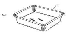
図に示す装置は、深絞りによってシート材料のブランク2からパッケージ用トレイ1を形成するものである。シート材料は、被覆されていない厚紙若しくは紙、ポリマー被覆された厚紙若しくは紙、又は金属箔を付した厚紙若しくは紙でよく、場合によってはポリマー、金属、又は金属とポリマーの複合材の被覆が追加される。 The illustrated apparatus forms a
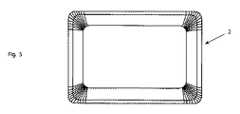
シート材料のブランク2を図5及び図6に示す。図5のブランク2は、1枚の長方形の平坦な材料であり、図7のような長方形のトレイ1を形成するのに好適である。図5のブランク2は、1枚の楕円形の平坦な材料であり、楕円形のトレイを形成するのに好適である。ブランクには、ブランクの外周に対して横切るように走る、押圧されたスコアラインが設けられている。図5の長方形ブランクは、スコアラインを角部だけに有するのに対し、図6の楕円形ブランクは、外周全体にわたって広がるスコアラインを有する。スコアラインの生成するに必要な押圧工程は先行技術で知られており、本明細書にはその詳細を記載しない。 A blank 2 of sheet material is shown in FIGS. The blank 2 in FIG. 5 is a single rectangular flat material and is suitable for forming the
スコアラインをシート材料のブランクに形成する代替法は、機械的な又はレーザーによる切り込みであり、材料に穴をあけること無く局所的に材料を彫るように制御される。 An alternative method of forming scorelines in a blank of sheet material is mechanical or laser scoring, which is controlled to engrave the material locally without punching the material.
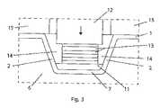
図1及び図2に示す装置は、主要部品として、外側からトレイを成形するための雌成形型3と、内側からトレイを成形するための雄成形型4と、深絞り工程の最中にシート材料のブランクを保持して周縁フランジ部をトレイに形成するためのクランプ手段5とを備える。 The apparatus shown in FIGS. 1 and 2 includes, as main components, a female molding die 3 for molding a tray from the outside, a male molding die 4 for molding a tray from the inside, and a sheet during the deep drawing process. Clamping means 5 for holding a blank of material and forming a peripheral flange on the tray.
雌成形型3は、形成されるトレイ1の形に概ね対応するキャビティ7を有するフレーム6を備える。図1及び図2に示される具体例では、キャビティ7に組み込まれる別個の底板8が存在する。この底板8は、形成されるトレイの深さを減少させるためのスペーサープレート9を用いて持ち上げることができる。しかしながら、底板8がキャビティ7の底と同じ高さになるようにスペーサープレート9を取り外すこともでき、それにより、トレイ1の形及び深さはフレーム6のみにより決定される。 The
雌成形型3のフレーム6の下方には、加熱ユニット10が設けられる。 A heating unit 10 is provided below the
雄成形型4は、トレイ1の底を内側から形成するためのプランジャープレート11と、深絞り工程の最中静止したまま保持されることが好ましい雌成形型3に対して移動可能になっている本体部12とを備える。プランジャープレート11を本体部12から離間させるために、複数のスペーサープレート13がプランジャープレート11と本体部12との間に位置付けられている。雄成形型4が鉛直方向へ移動することにより、プランジャープレート11がシート材料のブランク2を雌成形型3のキャビティ7内へ押圧し、材料を、底板8及びキャビティの側壁によって決定される形状に適合させる。 The male mold 4 is movable relative to the
雄成形型4のスペーサープレート13の具体的な構成は、スペーサープレート13がトレイ3の水平断面よりも狭いことであり、その結果、プレート13の一群を囲む自由スペース14が、それらのプレートと、形成されるべきトレイ側壁との間に残る。このようにして、トレイ側壁の自由形成が可能になり、トレイの角部における皺の発生が制御され、シート材料の断裂が避けられる。 The specific configuration of the
クランプ手段5は、雄成形型4の本体部12を囲み、雄成形型4と独立して鉛直方向に移動可能なフレーム15を備える。図1及び図2の具体例では、フレーム15が上側のクランプを形成するのに対し、雌成形型3のフレーム6が下側のクランプとして機能する。クランプ15、16は、相互接触面を有し、これによりクランプ動作中にブランク2の縁部を所定位置で保持し、形成されるべきトレイ1に周縁フランジ部を形成する。 The clamp means 5 is provided with a
図1及び図2の装置は先ず、雌成形型3の底板8の位置がトレイ1の所望の深さに対応するように、対応する数のスペーサープレート9を下に設置することによって調整することで作動する。次に、予めスコアラインを施したシート材料のブランク2が、クランプ手段5と共に互いに離間した状態の雌成形型と雄成形型3、4との間に運ばれる。次いで、クランプフレーム15が雌成形型3のフレーム6に当接して、ブランク2の縁を深絞り操作のための所定の位置にクランプする。最後に、雄成形型4の本体部12が、プランジャープレート11及びスペーサープレート13と共に下方に移動し、プランジャープレートがキャビティ7に入ってブランク2を雌成形型3の底板8に対して押圧する。トレイ3の底は、プランジャープレート11の形状に一致する一方、トレイの側面は自由形成の空間を有しており、不適切な圧縮や破損のない一様に形成された皺を実現する。 The apparatus of FIGS. 1 and 2 is first adjusted by installing a corresponding number of spacer plates 9 below so that the position of the bottom plate 8 of the
図3の具体例は、雌成形型3に、別個の底板やスペーサープレートが無く、雌成形型3のキャビティ7だけで、形成中のトレイ1の全体の形及び深さを決定するという点で、図2の具体例を単純化したものである。雄成形型4のプランジャープレート11及びスペーサープレート13は、図1及び図2のものと同様である。クランプ手段15も同様である。 The specific example of FIG. 3 is that the
図4の具体例は、図2及び図3の先の具体例におけるものと同様の雄成形型4および上部クランプツールを備える。しかしながら、雌成形型3は異なっている。形成されるトレイ1の底に対応する形をしたキャビティ7を有する底フレーム部16が存在する。下側クランプフレーム17は、ネジ山の切られたネジ18を介して、底フレーム部16に接続されており、このネジ18を用いて部品16、17間の距離を精度良く調整し、それによって完成したトレイ1の深さを調整する。更なる重要な特徴は、トレイ側壁の両側に十分な自由スペースが存在し、したがって側壁を自由に形成する空間が増すことである。 The embodiment of FIG. 4 comprises a male mold 4 and upper clamp tool similar to those in the previous embodiments of FIGS. 2 and 3. However, the
Claims (11)
Translated fromJapanese(i)前記シート材料に、形成すべきトレイの外周に対して横切るようにスコアラインを設ける工程と、
(ii)前記スコアラインを施した前記シート材料を、前記トレイの底を外面側から形成するためのキャビティ(7)を備えた雌成形型(3)と、前記トレイの底を内面側から形成するためのプランジャー(11)を備えた雄成形型(4)との間に運ぶ工程と、
(iii)深絞り工程の間に前記シート材料(2)を保持するために、前記シート材料を、前記雌成形型及び雄成形型(3、4)を用いて前記トレイの前記外周に沿ってクランプする工程と、
(iv)前記キャビティの底と前記シート材料(2)を保持しているクランプの接触面との間で前記雄成形型が前記シート材料から側方に離間した状態で、前記トレイの底を形成して前記トレイを完成させるために前記プランジャー(11)を前記キャビティ(7)に対して移動させる工程であって、前記側方に離間した前記雄成形型により形成された自由空きスペースで、前記完成させるトレイの側壁を形成する前記シート材料の皺を前記スコアラインによって形成させる、工程と
を含み、前記自由空きスペースは、前記完成させるトレイの側壁の内側に位置していることを特徴とする方法。Tray (1) from sheet material (2)selected from the group consisting of paper, paperboard, cardboard, polymer-coated paper or cardboard, paper or cardboard with metal foil, metal, and metal-polymer composites In the method of deep drawing,
(I) providing a score line on the sheet material so as to cross the outer periphery of the tray to be formed,
(Ii) Forming the sheet material having the score lines, a female mold (3) having a cavity (7) for forming the bottom of the tray from the outer side, and the bottom of the tray from the inner side. Carrying between a male mold (4) equipped with a plunger (11) for
(Iii) using the female and male molds (3, 4) to hold the sheet material (2) along the outer periphery of the tray to hold the sheet material (2) during a deep drawing step. The step of clamping,
(Iv) in a state where the malemold between the bottom andthe sheet material (2) contact surface of the clampthat holds the cavityis laterally spaced from said sheet material, forming thebottom of said tray in the plunger (11) a step of moving relative to the cavity (7),the free empty space formed bythe male mold spaced frontSL sideto complete the tray and to forma wrinkle of the sheet material forming the side walls of the trayto thecompletion by the score line,seen including astep, the free empty space, that is located inside of the side wall of the tray to the complete How to characterize.
(i)前記シート材料(2)にスコアラインを設けるための手段と、
(ii)前記トレイの底を外面側から形成するためのキャビティ(7)を備える雌成形型(3)と、
(iii)前記トレイを形成するために前記キャビティに対して移動可能な、前記トレイの底を内面側から形成するためのプランジャー(11)を備える雄成形型(4)と、
(iv)前記シート材料(2)を保持し、トレイの周縁フランジ部を形成するための接触面を有するクランプ(6、15)とを備え、
(v)前記雌成形型(3)がキャビティ底板(8)を有し、スペーサープレート(9)が前記キャビティ底板の鉛直方向の位置を調整するために設けられている前記装置において、
前記キャビティの底と前記クランプの接触面との間の鉛直方向の範囲内で、前記雄成形型と雌成形型(3、4)とが側方に離間して、前記トレイ(1)の側壁を形成するための自由空きスペースを形成するようになっていることを特徴とする装置。Device for deep-drawing a tray (1) from a sheet material (2) using a method according to any one of claims 1 to8 ,
(I) means for providing a score line on the sheet material (2),
(Ii) a female mold (3) having a cavity (7) for forming the bottom of the tray from the outer surface side;
(Iii) a male mold (4) having a plunger (11) movable from the cavity to form the tray, for forming the bottom of the tray from the inner surface side;
(Iv) a clamp (6, 15) for holding the sheet material (2) and having a contact surface for forming a peripheral flange portion of the tray,
( V) In the device,wherein the female mold (3) has a cavity bottom plate (8), and a spacer plate (9) is provided for adjusting the vertical position of the cavity bottom plate ,
Themale mold and the female mold (3, 4) are laterally separated from each other within the range of the vertical direction between the bottom of the cavity andthe contact surface of the clamp, and the side wall of the tray (1). An apparatus, characterized in thatit is adapted to form a free empty space for forming the .
(i)前記シート材料(2)にスコアラインを設けるための手段と、
(ii)前記トレイの底を外面側から形成するためのキャビティ(7)を備える雌成形型(3)と、
(iii)前記トレイを形成するために前記キャビティに対して移動可能な、前記トレイの底を内面側から形成するためのプランジャー(11)を備える雄成形型(4)と、
(iv)前記シート材料(2)を保持し、トレイの周縁フランジ部を形成するための接触面を有するクランプ(6、15)とを備え、
(v)前記キャビティの底と前記クランプの接触面との間の鉛直方向の範囲内で、前記雄成形型と雌成形型(3、4)とが側方に離間して、前記トレイ(1)の側壁を形成するための自由空きスペースを形成するようになっている前記装置において、
前記雄成形型(4)が、前記トレイの底を内面側から形成するためのプランジャープレート(11)を有し、前記プランジャープレートの鉛直方向の位置を調整するためにスペーサープレート(13)が設けられていることを特徴とする装置。Device for deep-drawing a tray (1) from a sheet material (2) using a method according to any one of claims1-8 ,
(I) means for providing a score line on the sheet material (2),
(Ii) a female mold (3) having a cavity (7) for forming the bottom of the tray from the outer surface side;
(Iii) a male mold (4) having a plunger (11) movable from the cavity to form the tray, for forming the bottom of the tray from the inner surface side;
(Iv) a clamp (6, 15) for holding the sheet material (2) and having a contact surface for forming a peripheral flange portion of the tray,
(V) Within the vertical range between the bottom of the cavity and the contact surface of the clamp, the male mold and the female mold (3, 4) are laterally separated from each other, and the tray (1 in it are the device adapted to form afree empty space to form a side wall of)
The male mold (4) has a plunger plate (11) for forming the bottom of the tray from the inner surface side, and a spacer plate (13) for adjusting the vertical position of the plunger plate. A device provided with.
Applications Claiming Priority (3)
| Application Number | Priority Date | Filing Date | Title |
|---|---|---|---|
| SE1451243-8 | 2014-10-17 | ||
| SE1451243ASE540678C2 (en) | 2014-10-17 | 2014-10-17 | Method and apparatus for deep-drawing a tray from sheet material |
| PCT/IB2015/057700WO2016059516A1 (en) | 2014-10-17 | 2015-10-08 | Method and apparatus for deep-drawing a tray from sheet material |
Publications (2)
| Publication Number | Publication Date |
|---|---|
| JP2017537811A JP2017537811A (en) | 2017-12-21 |
| JP6732741B2true JP6732741B2 (en) | 2020-07-29 |
Family
ID=55746204
Family Applications (1)
| Application Number | Title | Priority Date | Filing Date |
|---|---|---|---|
| JP2017520465AExpired - Fee RelatedJP6732741B2 (en) | 2014-10-17 | 2015-10-08 | Method and apparatus for deep-drawing a tray from sheet material |
Country Status (10)
| Country | Link |
|---|---|
| US (1) | US11241855B2 (en) |
| EP (1) | EP3209482B1 (en) |
| JP (1) | JP6732741B2 (en) |
| DK (1) | DK3209482T3 (en) |
| ES (1) | ES2753415T3 (en) |
| PL (1) | PL3209482T3 (en) |
| PT (1) | PT3209482T (en) |
| RU (1) | RU2701824C2 (en) |
| SE (1) | SE540678C2 (en) |
| WO (1) | WO2016059516A1 (en) |
Families Citing this family (12)
| Publication number | Priority date | Publication date | Assignee | Title |
|---|---|---|---|---|
| LU100074B1 (en)* | 2017-02-09 | 2018-10-02 | Soremartec Sa | Process for hot forming of a sheet of wrapping made of plastic material |
| JP6684950B1 (en)* | 2018-06-26 | 2020-04-22 | マルホ発條工業株式会社 | Blister packing machine |
| CN109051100B (en)* | 2018-07-02 | 2020-04-24 | 黄仕 | Special laminating machine for bowl film |
| EP3845371A4 (en)* | 2018-08-30 | 2022-05-11 | Tokan Kogyo Co., Ltd. | PAPER COVER MANUFACTURING METHOD |
| EP3848297B1 (en) | 2018-09-04 | 2024-07-17 | Tokan Kogyo Co., Ltd. | Paper lid |
| US20200094509A1 (en)* | 2018-09-21 | 2020-03-26 | Changzhou City Cheng Xin Environmental Protection Technology Co., Ltd. | Method for Manufacturing Fibrous Paper-plastic Disc-shaped Product |
| JP6770787B1 (en)* | 2019-11-01 | 2020-10-21 | 朗 高野 | Lid member |
| CH717493A1 (en)* | 2020-06-03 | 2021-12-15 | Gietz Ag | Device and method for erecting containers with a functional wheel from flat blanks. |
| JP2024543215A (en) | 2021-12-01 | 2024-11-19 | グラフィック パッケージング インターナショナル エルエルシー | Method and system for forming a tray - Patents.com |
| WO2024062462A2 (en)* | 2022-09-23 | 2024-03-28 | Sacmi Cooperativa Meccanici Imola Societa' Cooperativa | Method and dose for forming an object with a natural fibre-based material |
| CN115570835B (en)* | 2022-10-09 | 2024-08-20 | 合肥哈工龙延智能装备有限公司 | Supporting tool forming mechanism for supporting integrated machine |
| WO2024249024A1 (en)* | 2023-05-31 | 2024-12-05 | Graphic Packaging International, Llc | Methods and systems for forming trays |
Family Cites Families (26)
| Publication number | Priority date | Publication date | Assignee | Title |
|---|---|---|---|---|
| US2296744A (en)* | 1938-06-18 | 1942-09-22 | Paul R Simmons | Apparatus for forming and deodorizing paper plates |
| US2305998A (en)* | 1941-10-22 | 1942-12-22 | Paul R Simmons | Apparatus for forming deodorized paper plates |
| US3054144A (en)* | 1959-01-23 | 1962-09-18 | American Seal Kap Corp | Apparatus for making paper containers |
| US3695084A (en) | 1970-11-24 | 1972-10-03 | Reynolds Metals Co | Nestable container and apparatus for and method of making same |
| US4026458A (en)* | 1975-03-27 | 1977-05-31 | International Paper Company | Deep drawn paperboard container and process for making it |
| GB1553975A (en) | 1975-09-04 | 1979-10-17 | Bosch Gmbh Robert | Light-weight packaging containers and a method and apparatus for producing such containers |
| GB1516766A (en)* | 1975-10-03 | 1978-07-05 | Peerless Mach & Tool Corp | Cold-forming sheet material |
| US4108941A (en)* | 1976-04-26 | 1978-08-22 | Dolco Packaging Corporation | Shear molding of reinforced latch |
| US4149841A (en)* | 1978-03-27 | 1979-04-17 | Peerless Machine & Tool Corporation | Apparatus of making a compartment tray |
| US4246223A (en)* | 1978-11-20 | 1981-01-20 | Peerless Machine And Tool Corporation | Method and apparatus of making a compartment tray |
| US4576565A (en)* | 1980-03-17 | 1986-03-18 | Chlystun Walter K | Apparatus for forming a dispensing container |
| DE3175548D1 (en)* | 1981-12-18 | 1986-12-11 | Champion Int Corp | An apparatus and method for forming a paperboard receptacle |
| US4755128A (en)* | 1986-09-30 | 1988-07-05 | Peerless Machine & Tool Corporation | Apparatus for releasing a press-formed article from a die set |
| US4778439A (en)* | 1987-06-18 | 1988-10-18 | Peerless Machine & Tool Corporation | Apparatus and method for forming a clamshell assembly |
| US5040962A (en) | 1989-12-12 | 1991-08-20 | The Dow Chemical Company | Reaction injection molding apparatus with internal frame and shear edge |
| EP1051293A4 (en)* | 1997-12-03 | 2002-07-17 | Peerless Machine & Tool | CUTTING FORM FOR PRESSED PAPER |
| US6585630B2 (en) | 2000-12-19 | 2003-07-01 | Wen-Long Dai | Container manufacturing method and device |
| JP4121832B2 (en)* | 2002-11-01 | 2008-07-23 | 東罐興業株式会社 | Method and apparatus for manufacturing molded container and molded container |
| ES2401736T3 (en) | 2003-11-11 | 2013-04-24 | Graphic Packaging International, Inc. | Embedded cardboard container |
| ITVE20070025A1 (en) | 2007-04-20 | 2008-10-21 | Gruppo X Di X Gruppo S R L | METHOD OF FORMING MATERIALS IN SHEET, PARTICULARLY OF PAPER MATERIALS.- |
| FI122768B (en) | 2007-12-12 | 2012-06-29 | Stora Enso Oyj | Procedure for the manufacture of a package, and a package |
| RU2497678C2 (en)* | 2008-08-12 | 2013-11-10 | Стора Энсо Ойй | Moulding system for cardboard container production |
| IT1398330B1 (en) | 2010-02-09 | 2013-02-22 | Sarong Spa | APPARATUS FOR FORMING AND LABELING AN OBJECT AND OBJECT OBTAINED SO ITSELF |
| EP3168023B1 (en)* | 2011-09-09 | 2019-02-06 | Graphic Packaging International, LLC | Tool and method for forming a three dimensional article or container |
| JP2013082109A (en)* | 2011-10-07 | 2013-05-09 | Toyo Seikan Kaisha Ltd | Paper molding with less wrinkle and production method thereof |
| SE539446C2 (en)* | 2013-11-04 | 2017-09-26 | Stora Enso Oyj | Method and apparatus for deep drawing a tray from fiber-based sheet material |
- 2014
- 2014-10-17SESE1451243Apatent/SE540678C2/ennot_activeIP Right Cessation
- 2015
- 2015-10-08ESES15849921Tpatent/ES2753415T3/enactiveActive
- 2015-10-08EPEP15849921.0Apatent/EP3209482B1/enactiveActive
- 2015-10-08PLPL15849921Tpatent/PL3209482T3/enunknown
- 2015-10-08DKDK15849921Tpatent/DK3209482T3/enactive
- 2015-10-08JPJP2017520465Apatent/JP6732741B2/ennot_activeExpired - Fee Related
- 2015-10-08WOPCT/IB2015/057700patent/WO2016059516A1/enactiveApplication Filing
- 2015-10-08USUS15/518,178patent/US11241855B2/enactiveActive
- 2015-10-08PTPT158499210Tpatent/PT3209482T/enunknown
- 2015-10-08RURU2017116978Apatent/RU2701824C2/enactive
Also Published As
| Publication number | Publication date |
|---|---|
| JP2017537811A (en) | 2017-12-21 |
| EP3209482B1 (en) | 2019-07-31 |
| PT3209482T (en) | 2019-11-04 |
| DK3209482T3 (en) | 2019-10-28 |
| PL3209482T3 (en) | 2020-06-01 |
| EP3209482A1 (en) | 2017-08-30 |
| WO2016059516A1 (en) | 2016-04-21 |
| RU2017116978A (en) | 2018-11-20 |
| US20170305097A1 (en) | 2017-10-26 |
| US11241855B2 (en) | 2022-02-08 |
| RU2701824C2 (en) | 2019-10-01 |
| EP3209482A4 (en) | 2018-07-11 |
| SE1451243A1 (en) | 2016-04-18 |
| ES2753415T3 (en) | 2020-04-08 |
| RU2017116978A3 (en) | 2019-04-22 |
| SE540678C2 (en) | 2018-10-09 |
Similar Documents
| Publication | Publication Date | Title |
|---|---|---|
| JP6732741B2 (en) | Method and apparatus for deep-drawing a tray from sheet material | |
| US11383473B2 (en) | Deep-drawn paper tray, a method and an apparatus for making it, and a tray-formed product package | |
| JP2021119055A (en) | Formed thermoplastic article with smooth edges | |
| EP3077192B1 (en) | Sealable package and production thereof | |
| EP3066011B1 (en) | Method and apparatus for deep-drawing a tray from sheet material | |
| JP7568623B2 (en) | Manufacturing process for producing sealed disposable food containers using a sealing head with a specific profile having ribs | |
| RU2807162C2 (en) | Method for manufacturing healed disposable containers for food products such as coffee capsules, including scoring stage |
Legal Events
| Date | Code | Title | Description |
|---|---|---|---|
| A621 | Written request for application examination | Free format text:JAPANESE INTERMEDIATE CODE: A621 Effective date:20180725 | |
| A131 | Notification of reasons for refusal | Free format text:JAPANESE INTERMEDIATE CODE: A131 Effective date:20190926 | |
| A521 | Request for written amendment filed | Free format text:JAPANESE INTERMEDIATE CODE: A523 Effective date:20191224 | |
| TRDD | Decision of grant or rejection written | ||
| A01 | Written decision to grant a patent or to grant a registration (utility model) | Free format text:JAPANESE INTERMEDIATE CODE: A01 Effective date:20200626 | |
| A61 | First payment of annual fees (during grant procedure) | Free format text:JAPANESE INTERMEDIATE CODE: A61 Effective date:20200708 | |
| R150 | Certificate of patent or registration of utility model | Ref document number:6732741 Country of ref document:JP Free format text:JAPANESE INTERMEDIATE CODE: R150 | |
| R250 | Receipt of annual fees | Free format text:JAPANESE INTERMEDIATE CODE: R250 | |
| LAPS | Cancellation because of no payment of annual fees |