JP6730484B2 - Distribution device, distribution system, and distribution program - Google Patents
Distribution device, distribution system, and distribution programDownload PDFInfo
- Publication number
- JP6730484B2 JP6730484B2JP2019082937AJP2019082937AJP6730484B2JP 6730484 B2JP6730484 B2JP 6730484B2JP 2019082937 AJP2019082937 AJP 2019082937AJP 2019082937 AJP2019082937 AJP 2019082937AJP 6730484 B2JP6730484 B2JP 6730484B2
- Authority
- JP
- Japan
- Prior art keywords
- terminal
- rtp
- packet
- extension header
- transmission
- Prior art date
- Legal status (The legal status is an assumption and is not a legal conclusion. Google has not performed a legal analysis and makes no representation as to the accuracy of the status listed.)
- Active
Links
- 230000005540biological transmissionEffects0.000claimsdescription479
- 238000004891communicationMethods0.000description78
- 238000000034methodMethods0.000description47
- 238000012986modificationMethods0.000description18
- 230000004048modificationEffects0.000description18
- 230000000694effectsEffects0.000description16
- 238000012545processingMethods0.000description13
- 230000004044responseEffects0.000description13
- 238000012544monitoring processMethods0.000description12
- 238000005516engineering processMethods0.000description8
- 238000010586diagramMethods0.000description7
- 230000008569processEffects0.000description6
- 230000008859changeEffects0.000description5
- 230000008901benefitEffects0.000description4
- 239000000284extractSubstances0.000description4
- 230000006870functionEffects0.000description4
- 239000000969carrierSubstances0.000description3
- 230000001413cellular effectEffects0.000description3
- 238000012423maintenanceMethods0.000description3
- 230000008054signal transmissionEffects0.000description3
- 238000012790confirmationMethods0.000description2
- 230000003111delayed effectEffects0.000description2
- 239000000203mixtureSubstances0.000description2
- 238000009434installationMethods0.000description1
- 230000007774longtermEffects0.000description1
- 230000003287optical effectEffects0.000description1
- 239000013307optical fiberSubstances0.000description1
- 230000008520organizationEffects0.000description1
- 238000003825pressingMethods0.000description1
- 230000002265preventionEffects0.000description1
- 239000004065semiconductorSubstances0.000description1
Images


Landscapes
- Data Exchanges In Wide-Area Networks (AREA)
- Mobile Radio Communication Systems (AREA)
- Telephonic Communication Services (AREA)
Description
Translated fromJapanese本発明は、データの配信を行なうための、配信装置、配信システム及び配信プログラムに関する。 The present invention relates to a distribution device, a distribution system, and a distribution program for distributing data.
トランシーバや無線機を用いた、プッシュ・ツー・トーク(Push to Talk)通信と呼ばれる通信方式が広く用いられている。かかるプッシュ・ツー・トーク通信は、全二重の音声通信ではなく、半二重の音声通信ではあるが、1対多のグループ一斉音声通信を可能とするものである。 A communication method called push to talk communication using a transceiver or a radio is widely used. Such push-to-talk communication is not full-duplex voice communication but half-duplex voice communication, but enables one-to-many group simultaneous voice communication.
このような、トランシーバや無線機といった機器を用いたプッシュ・ツー・トークは従来から長らく利用されている。そのため、以降の説明においては、トランシーバや無線機を用いたプッシュ・ツー・トークを「トランシーバ等によるプッシュ・ツー・トーク通信」と記載する。 Push-to-talk using devices such as transceivers and radios has been used for a long time. Therefore, in the following description, push-to-talk using a transceiver or radio will be referred to as "push-to-talk communication by a transceiver or the like".
その後、通信事業者が提供する携帯電話網が普及したことに伴い、携帯電話端末を、トランシーバや無線機のように利用することを特徴としたコミュニケーション手段である、PoC(Push-to-Talk over Cellular)が登場した。 Since then, with the spread of mobile phone networks provided by communication carriers, PoC (Push-to-Talk over) is a communication means characterized by using mobile phone terminals like transceivers and radios. Cellular) has appeared.
PoCは、モバイル関連のWebアプリケーション技術の標準化を行っている団体であるOMA(Open Mobile Alliance)によって、IMS(IP Multimedia Subsystem)の一部として定義、標準化されている。 PoC is defined and standardized as a part of IMS (IP Multimedia Subsystem) by OMA (Open Mobile Alliance), which is an organization that standardizes mobile-related Web application technologies.
このような、PoCに関連する技術の一例が、例えば特許文献1に記載されている。特許文献1に記載の技術では、プッシュ・ツー・トークに参加する端末装置のグループを決定する場合に、予めグループに参加する端末装置を決定するのではなく、所定の条件に基づいて動的にグループ及びグループに参加する端末装置を決定する。 An example of such a technology related to PoC is described in Patent Document 1, for example. In the technique described in Patent Document 1, when a group of terminal devices that participate in push-to-talk is determined, the terminal devices that participate in the group are not determined in advance, but dynamically based on a predetermined condition. A group and a terminal device that participates in the group are determined.
上述したPoCは、プッシュ・ツー・トーク通信を低コストで利用できるという利点がある。そのため、PoCは、一時期普及した。 The PoC described above has an advantage that push-to-talk communication can be used at low cost. Therefore, PoC became popular for a while.
しかしながら、基本的な通信手段としては、PoCよりも電子メールがより広く普及し、結果としてPoCの需要は、個人用ではなく業務用に限られるようなケースが多くなった。そして、利用者の減少等を理由に、国内の通信事業者は2009年から2011年頃に相次いでPoCを利用するためのサービスの提供を終了した。すなわち、PoCは、結果として広く普及してはいない。 However, as a basic communication means, electronic mail has become more widespread than PoC, and as a result, the demand for PoC is often limited to business use rather than personal use. Then, due to the decrease in the number of users, domestic telecommunications carriers have finished providing services for using PoC in succession from 2009 to 2011. That is, PoC is not widely used as a result.
このようにPoCが広く普及しなかった原因の1つとしては、PoCを従来型のプッシュ・ツー・トーク通信と同じ用途で使用することが困難であったからと考えられる。 It is considered that one of the reasons why PoC has not spread widely is that it is difficult to use PoC for the same purpose as the conventional push-to-talk communication.
具体的に述べると、従来型のプッシュ・ツー・トーク通信は、自営無線網を構築することにより、1の発信元から多の発信先への一斉通信における「多」の数(以降、「グループ内端末同時通信数」と記載する)を非常に多くしたり、広域で提供したりすることが可能であった。しかしながら、PoCを、このような従来型のプッシュ・ツー・トーク通信と同じ用途で用いることはこれまでの技術では実現困難である。 Specifically, the conventional push-to-talk communication is the number of “many” (hereinafter, “group”) in simultaneous communication from one sender to many destinations by constructing a self-employed wireless network. It was possible to provide a large number of simultaneous communication (internal terminal simultaneous communication). However, using PoC for the same purpose as such conventional push-to-talk communication is difficult to realize with conventional technology.
その理由について説明する。トランシーバや無線機を用いた無線通信であれば、送信元の無線機が電波を送信し、複数台の無線機が、その電波をそれぞれ受信できれば、音声を再生することが可能である。 The reason will be described. In the case of wireless communication using a transceiver or a wireless device, it is possible to reproduce voice if the wireless device of the transmission source transmits a radio wave and a plurality of wireless devices can receive the respective radio waves.
しかし、携帯電話機及びIP網を利用する場合には、音声をRTP(Real-time Transport Protocol)に準拠してパケット化したRTPパケットや、配信制御用のIPパケットをそれぞれの携帯電話端末に向けて個々に配信しなければならなくなる。 However, when using a mobile phone and an IP network, an RTP packet in which voice is packetized in conformity with RTP (Real-time Transport Protocol) and an IP packet for distribution control are directed to each mobile phone terminal. It will have to be delivered individually.
そのため、理論上はグループ内端末同時通信数を増加させることが可能であっても、実際にはネットワーク帯域等の物理的制約があることから、グループ内端末同時通信数を増加させることが困難となる。 Therefore, even if it is theoretically possible to increase the number of simultaneous communication of terminals within a group, it is difficult to increase the number of simultaneous communication of terminals within a group due to physical restrictions such as network bandwidth. Become.
結果として、PoCの需要が業務用に限られるケースが多いという背景があるにも関わらず、エリアの広さやグループ内端末同時通信数等の規模が、業務用に使用するには十分耐えうるものでなかったことが、PoCが利用されなくなった原因であると考えられる。 As a result, despite the fact that the demand for PoC is often limited to business use, the size of the area and the number of simultaneous communication of terminals in the group are sufficient to be used for business use. It was considered that the reason why PoC was not used was that it was not.
以上まとめると、これまでの技術では、PoC等の技術を利用する場合に、グループ内端末同時通信数を増加させたり、より広域でサービスを提供したりする、といったことが困難であった。 In summary, it has been difficult with the conventional technology to increase the number of simultaneous communication of terminals in the group or provide a service in a wider area when using the technology such as PoC.
そこで、本発明は、PoC等の技術を利用する場合に、グループ内端末同時通信数を増加させたり、広域でサービスを提供したりすることが可能な、配信装置、配信システム、配信方法及び配信プログラムを提供することを目的とする。 Therefore, the present invention, when using a technology such as PoC, is capable of increasing the number of simultaneous terminal communication within a group and providing a service in a wide area, a distribution device, a distribution system, a distribution method, and a distribution. The purpose is to provide the program.
本発明の第1の観点によれば、配信先の端末群を特定するための識別情報を、第1のプロトコルに準拠したヘッダに格納したパケットを受信し、前記識別情報に基づいて、配信先の端末群に含まれる各端末それぞれの第2のプロトコルに準拠したアドレスを取得し、前記受信したパケットを複製し、該複製したパケットを、前記取得した各アドレス宛に送信することを特徴とする配信装置が提供される。 According to a first aspect of the present invention, a packet in which identification information for identifying a terminal group of a delivery destination is stored in a header conforming to the first protocol is received, and the delivery destination is received based on the identification information. Acquiring an address compliant with the second protocol of each terminal included in the terminal group, copying the received packet, and transmitting the copied packet to each of the acquired addresses. A distribution device is provided.
本発明の第2の観点によれば、上記本発明の第1の観点により提供される配信装置と、端末とを含む配信システムであって、前記配信装置は、前記複製したパケットに、パケットの送信元の端末を表す情報又はパケットの送信元の端末のユーザを表す情報何れか又は双方を含ませ、前記配信装置からパケットを配信された端末は、パケットに含まれているパケットの送信元の端末を表す情報又はパケットの送信元の端末のユーザを表す情報の何れか又は双方を出力することを特徴とする配信システムが提供される。 According to a second aspect of the present invention, there is provided a delivery system including the delivery device provided by the first aspect of the present invention and a terminal, wherein the delivery device adds a packet to the copied packet. Either the information indicating the terminal of the transmission source or the information indicating the user of the terminal of the transmission source of the packet is included or both, and the terminal to which the packet is distributed from the distribution device is the source of the packet included in the packet. A distribution system is provided, which outputs either or both of information indicating a terminal and information indicating a user of a terminal of a transmission source of a packet.
本発明の第3の観点によれば、上記本発明の第1の観点により提供される配信装置と、端末とを含む配信システムであって、前記配信装置は、前記配信先の端末群に含まれる各端末の何れにも送信権を付与していない場合に、前記パケットの送信元の端末に送信権を付与し、前記送信権を付与した端末が送信したパケットを配信の対象とし、前記送信権を付与された端末は、ユーザの操作に基づいて、送信権開放要求をパケットに含ませて前記配信装置に送信し、前記配信装置及び前記配信装置からパケットの配信を受けた端末は、前記パケットに前記送信権開放要求が含まれている場合に、前記送信権を付与された端末の送信権を剥奪することを特徴とする配信システムが提供される。 According to a third aspect of the present invention, there is provided a delivery system including the delivery device provided by the first aspect of the present invention and a terminal, wherein the delivery device is included in the delivery destination terminal group. When the transmission right is not given to any of the terminals to be transmitted, the transmission right is given to the terminal that is the source of the packet, and the packet transmitted by the terminal to which the transmission right is given is targeted for distribution. The terminal to which the right has been granted transmits the transmission right release request to the distribution device by including the transmission right release request in the packet based on the user's operation, and the distribution device and the terminal that receives the packet distribution from the distribution device are A distribution system is provided, wherein when the packet includes the transmission right release request, the transmission right of the terminal to which the transmission right is given is deprived.
本発明の第4の観点によれば、配信先の端末群を特定するための識別情報を、第1のプロトコルに準拠したヘッダに格納したパケットを受信し、前記識別情報に基づいて、配信先の端末群に含まれる各端末それぞれの第2のプロトコルに準拠したアドレスを取得し、前記受信したパケットを複製し、該複製したパケットを、前記取得した各アドレス宛に送信する配信装置としてコンピュータを機能させることを特徴とする配信プログラムが提供される。 According to a fourth aspect of the present invention, a packet in which identification information for identifying a terminal group of a delivery destination is stored in a header compliant with the first protocol is received, and the delivery destination is received based on the identification information. A computer as a distribution device that acquires an address compliant with the second protocol of each terminal included in the terminal group, duplicates the received packet, and transmits the duplicated packet to each of the obtained addresses. A distribution program is provided which is characterized by making it function.
本発明によれば、PoC等の技術を利用する場合に、グループ内端末同時通信数を増加させたり、広域でサービスを提供したりすることが可能となる。 According to the present invention, when a technology such as PoC is used, it is possible to increase the number of simultaneous terminal communication within a group and provide a service in a wide area.
まず、本発明の実施形態の概略を説明する。本発明の実施形態は、携帯電話端末を、トランシーバや無線機のように利用することを特徴としたコミュニケーション手段であるPoC(Push-to-Talk over Cellular)等の技術分野に好適な実施形態である。 First, an outline of an embodiment of the present invention will be described. The embodiment of the present invention is an embodiment suitable for a technical field such as PoC (Push-to-Talk over Cellular) which is a communication means characterized by using a mobile phone terminal like a transceiver or a wireless device. is there.
具体的には、プッシュ・ツー・トーク通信を、従来型のプッシュ・ツー・トーク通信と同程度の大規模かつ広域での利用を可能としつつ、携帯電話端末及び携帯電話事業者網を用いてより低コストで提供可能なPoCグループ一斉音声通信を実現することを目的とする。 Specifically, while enabling push-to-talk communication to be used on a large-scale and wide-area basis that is the same as conventional push-to-talk communication, using mobile phone terminals and mobile phone carrier networks The purpose is to realize PoC group simultaneous voice communication that can be provided at a lower cost.
そのために、本実施形態における配信装置が、任意の送信元端末からのRTPパケットを、予め設定した端末のグループ情報及び端末の死活情報に従って、それぞれの送信先端末に向けた複数パケットに複製して配信する。 Therefore, the distribution device according to the present embodiment copies an RTP packet from an arbitrary source terminal into a plurality of packets for each destination terminal according to preset group information of the terminal and alive information of the terminal. To deliver.
更に、本実施形態における配信装置が、RTPパケットを複製する際に、IPヘッダの送信元IPアドレス情報を、配信装置のIPアドレスに変換して配信するようにしても良い。 Further, when the distribution device according to the present embodiment copies an RTP packet, the source IP address information of the IP header may be converted into the IP address of the distribution device and distributed.
更に、送信元端末は、RTPパケットの送信元IDであるSSRC(Synchrozination Source)フィールドに送信元端末IDを付加して配信装置に通知するようにしても良い。
あるいは、送信元端末は、RTPパケットのRTP拡張ヘッダに、グループID・端末ID・特権者情報などの情報を付加して通知するようにしても良い。そして、本実施形態における配信装置は、これらの通知に基づいて送信先端末所属グループやその他の情報を認識して配信制御をするようにしても良い。Further, the transmission source terminal may add the transmission source terminal ID to the SSRC (Synchrozination Source) field, which is the transmission source ID of the RTP packet, and notify the distribution device.
Alternatively, the transmission source terminal may add information such as a group ID, terminal ID, and privileged person information to the RTP extension header of the RTP packet to notify. Then, the distribution device according to the present embodiment may recognize the group to which the destination terminal belongs and other information based on these notifications to control distribution.
以上が本発明の概略である。 The above is the outline of the present invention.
次に、本発明の実施の形態について図面を参照して詳細に説明する。
[構成の説明]
まず、本発明の実施形態である、配信システムS100の基本的構成について図1を参照して説明する。Next, embodiments of the present invention will be described in detail with reference to the drawings.
[Description of configuration]
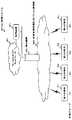
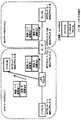
First, a basic configuration of a distribution system S100, which is an embodiment of the present invention, will be described with reference to FIG.
図1を参照すると、配信システムS100は、配信装置E1、第1の端末T1乃至第nの端末Tn、ローカルエリアネットワークN1、専用線網N2及び事業者携帯電話用パケット通信網N3を含む。 Referring to FIG. 1, a distribution system S100 includes a distribution device E1, a first terminal T1 to an n-th terminal Tn, a local area network N1, a leased line network N2, and a packet communication network N3 for a carrier cell phone.
ここで、配信装置E1は、PoCグループ一斉音声通信を実現するための装置である。
配信装置E1は、例えば本実施形態特有のプログラムを組み込んだサーバ装置により実現される。Here, the distribution device E1 is a device for realizing PoC group simultaneous voice communication.
The distribution device E1 is realized by, for example, a server device that incorporates a program specific to this embodiment.
また、第1の端末T1乃至第nの端末Tnは、ユーザが利用する通信端末である。第1の端末T1乃至第nの端末Tnは、例えば、携帯電話機により実現される。 Further, the first terminal T1 to the nth terminal Tn are communication terminals used by the user. The first terminal T1 to the n-th terminal Tn are realized by, for example, a mobile phone.
また、ローカルエリアネットワークN1は、例えば配信装置E1を利用するユーザが使用するネットワークである。配信装置E1は、ローカルエリアネットワークN1に接続されている。 The local area network N1 is a network used by a user who uses the distribution device E1, for example. The distribution device E1 is connected to the local area network N1.
また、事業者携帯電話用パケット通信網N3は、例えば携帯電話機のキャリアが提供する通信網である。また、配信装置E1と事業者携帯電話用パケット通信網N3は、配信装置E1を利用するユーザ用に設けられた専用線網N2を介してネットワーク接続される。
そして、このネットワーク接続を利用して配信装置E1と、第1の端末T1乃至第nの端末Tnとは通信を行なう。The carrier mobile phone packet communication network N3 is, for example, a communication network provided by a carrier of a mobile phone. In addition, the distribution device E1 and the packet communication network N3 for enterprise mobile phones are network-connected via a dedicated line network N2 provided for a user who uses the distribution device E1.
Then, using this network connection, the distribution device E1 and the first terminal n1 to the nth terminal Tn communicate with each other.
また、本実施形態では、第1の端末T1乃至第nの端末Tnは、それぞれが何れかのグループに所属しているものとする。ここでいう「グループ」とは、トランシーバの周波数や、無線機のチャネルに相当するものであり、通話先とする端末群を選択するために使用する。 Further, in the present embodiment, each of the first terminal T1 to the nth terminal Tn is assumed to belong to any group. The “group” mentioned here corresponds to a frequency of a transceiver or a channel of a radio device, and is used to select a terminal group as a call destination.
グループの設定方法には種々の方法が考えられる。例えば、何れのグループに、何れの端末が所属しているのかを表す情報を予め配信装置E1に記憶させることにより、グループの設定を行なうようにしても良い。 Various methods are conceivable as a method of setting a group. For example, the group setting may be performed by storing information indicating which terminal belongs to which group in the distribution device E1 in advance.
また、そうではなく、ユーザの操作を端末で受け付けるようにし、この操作に応じてグループの設定を行なうようにしても良い。つまり、通話する端末群をユーザに選択させることにより、動的にグループの設定を行なうようにしても良い。 Alternatively, the user's operation may be accepted by the terminal, and the group may be set according to the operation. That is, the group may be dynamically set by allowing the user to select a terminal group to talk with.
更に、これらを組み合わせて、予め配信装置E1に設定した範囲で、通話する端末群をユーザに動的に選択させるようにしても良い。例えば、予め或るユーザの端末を第1のグループと第2のグループに設定しておく。そして、この或るユーザに、通話対象とするグループを、第1のグループと第2のグループの何れかから選択させるようにしてもよい。
またそうではなく、例えば第1の端末T1、第2の端末T2、第3の端末T3及び第4の端末T4が或る1つのグループに所属するとして予め配信装置E1に設定しておく。そして、通信時に、発信元となる端末(例えば、第1の端末T1)のユーザにこの4台の端末の中の残りの3台(例えば、第2の端末T2、第3の端末T3及び第4の端末T4)から通話する端末群を選択させるようにしても良い。Further, these may be combined to allow the user to dynamically select a terminal group to make a call within a range preset in the distribution device E1. For example, the terminals of a certain user are set in advance in the first group and the second group. Then, this certain user may be made to select the group to be called from either the first group or the second group.
Alternatively, for example, the first terminal T1, the second terminal T2, the third terminal T3, and the fourth terminal T4 are set in the distribution apparatus E1 in advance assuming that they belong to a certain group. Then, at the time of communication, the user of the terminal (for example, the first terminal T1) that is the source of transmission has the remaining three terminals (for example, the second terminal T2, the third terminal T3, and It is also possible to select a terminal group to talk with from four terminals T4).
また、以下の説明では、第1の端末T1、第3の端末T3及び第nの端末Tn等はグループG1に所属しており、第2の端末T2等はグループG2に所属しているものとする。
なお、上記の文章にて「・・・第nの端末Tn等」、とのように「等」との文言を付加している理由であるが、グループG1やグループG2に、図示を省略している他の端末が含まれても良いことを想定しているからである。Further, in the following description, it is assumed that the first terminal T1, the third terminal T3, the nth terminal Tn and the like belong to the group G1, and the second terminal T2 and the like belong to the group G2. To do.
The reason for adding the word “etc.” such as “...nth terminal Tn etc.” in the above sentence is not shown in the groups G1 and G2. This is because it is assumed that other terminals that are installed may be included.
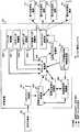
次に、図2を参照して、特に配信装置E1に含まれる機能ブロックについて説明する。
また、各機能ブロックによる処理又はデータの流れや、RTPパケットの流れについても説明する。なお、図3にも凡例として記載しているが、図3における実線による矢印は、各機能ブロックによる処理又はデータの流れを表している。また、図3における破線による矢印は、RTPパケットの流れを表している。また、機能ブロックの説明とは深く関係しない、ローカルエリアネットワークN1、専用線網N2及び事業者携帯電話用パケット通信網N3については図2での図示を省略する。Next, the functional blocks included in the distribution device E1 will be described with reference to FIG.
The flow of processing or data by each functional block and the flow of RTP packets will also be described. In addition, although it is also described as a legend in FIG. 3, solid line arrows in FIG. 3 represent processes or data flows by the respective functional blocks. In addition, the dashed arrow in FIG. 3 represents the flow of RTP packets. Further, the local area network N1, the leased line network N2, and the packet communication network N3 for carrier cellular phones, which are not deeply related to the description of the functional blocks, are not shown in FIG.
図2を参照すると配信システムS100は、配信装置E1、送信元端末S1、及び第1の送信先端末R1乃至第Nの送信先端末Rnを含む。 Referring to FIG. 2, the distribution system S100 includes a distribution device E1, a transmission source terminal S1, and a first transmission destination terminal R1 to an Nth transmission destination terminal Rn.
ここで、送信元端末S1と、第1の送信先端末R1乃至第Nの送信先端末Rnは、それぞれが図1に表される第1の端末T1乃至第nの端末Tnの何れかに相当するものである。また、各端末は、送信先及び送信元の役割が固定されているものではない。つまり、送信元端末S1は、第1の送信先端末R1乃至第Nの送信先端末Rnになり得る。同様に、第1の送信先端末R1乃至第Nの送信先端末Rnは送信元端末S1になり得る。なお、以下の説明において、第1の送信先端末R1乃至第Nの送信先端末Rnの何れかの端末を特定することなく指す場合には、単に「端末R」と記載する。 Here, the source terminal S1 and the first destination terminal R1 to the Nth destination terminal Rn correspond to any of the first terminal T1 to the nth terminal Tn shown in FIG. 1, respectively. To do. Moreover, the roles of the destination and the source of each terminal are not fixed. That is, the source terminal S1 can be the first destination terminal R1 to the Nth destination terminal Rn. Similarly, the first destination terminal R1 to the Nth destination terminal Rn can be the source terminal S1. In the following description, when referring to any of the first destination terminal R1 to the Nth destination terminal Rn without specifying them, they are simply referred to as “terminal R”.
また、配信装置E1は、RTPパケット受信部M1、受信RTPパケット記憶部M2、送信元端末ID制御部M3、送信権取得制御部M4、RTPパケット複製部M5、送信RTPパケット記憶部M6、RTPパケット送信部M7、IPヘッダ制御部M8−1、UDPヘッダ制御部M8−2、RTPヘッダ制御部M8−3、RTP拡張ヘッダ制御部M8−4及びグループ所属端末群情報記憶部D1を含む。 The distribution device E1 also includes an RTP packet receiving unit M1, a received RTP packet storage unit M2, a source terminal ID control unit M3, a transmission right acquisition control unit M4, an RTP packet duplication unit M5, a transmission RTP packet storage unit M6, and an RTP packet. It includes a transmission unit M7, an IP header control unit M8-1, a UDP header control unit M8-2, an RTP header control unit M8-3, an RTP extension header control unit M8-4, and a group belonging terminal group information storage unit D1.
RTPパケット受信部M1は、送信元端末S1が送信したRTPパケットを受信する。 The RTP packet receiving unit M1 receives the RTP packet transmitted by the transmission source terminal S1.
受信RTPパケット記憶部M2は、RTPパケット受信部M1が受信したRTPパケットを一時的に記憶する。 The reception RTP packet storage unit M2 temporarily stores the RTP packet received by the RTP packet reception unit M1.
送信元端末ID制御部M3は、RTPパケットに含まれるSSRC(送信元ID)フィールドから送信元端末IDを抽出して、抽出した送信元端末IDを送信権取得制御部M4やRTPパケット複製部M5に出力する。 The transmission source terminal ID control unit M3 extracts the transmission source terminal ID from the SSRC (transmission source ID) field included in the RTP packet, and uses the extracted transmission source terminal ID as the transmission right acquisition control unit M4 or the RTP packet duplication unit M5. Output to.
送信権取得制御部M4は、送信元端末S1に送信権を与えるか否かを決定する。 The transmission right acquisition control unit M4 determines whether to give the transmission right to the transmission source terminal S1.
RTPパケット複製部M5は、RTPパケットの複製を作成する。 The RTP packet copying unit M5 creates a copy of the RTP packet.
送信RTPパケット記憶部M6は、RTPパケット複製部M5が作成したRTPパケットの複製を一時的に記憶する。 The transmission RTP packet storage unit M6 temporarily stores the copy of the RTP packet created by the RTP packet copy unit M5.
RTPパケット送信部M7は、送信RTPパケット記憶部M6が記憶しているRTPパケットの複製を、第1の送信先端末R1乃至第Nの送信先端末Rnの内の、送信先となる端末に対して送信する。 The RTP packet transmission unit M7 copies a copy of the RTP packet stored in the transmission RTP packet storage unit M6 to a destination terminal among the first destination terminal R1 to the Nth destination terminal Rn. To send.
IPヘッダ制御部M8−1は、RTPパケット複製部M5が作成するRTPパケットの複製のIPヘッダに所定の情報を書き込む。また、UDPヘッダ制御部M8−2は、RTPパケット複製部M5が作成するRTPパケットの複製のUDPヘッダに所定の情報を書き込む。更に、RTPヘッダ制御部M8−3は、RTPパケット複製部M5が作成するRTPパケットの複製のRTPヘッダに所定の情報を書き込む。更に、RTP拡張ヘッダ制御部M8−4は、RTPパケット複製部M5が作成するRTPパケットの複製のRTP拡張ヘッダに所定の情報を書き込む。 The IP header control unit M8-1 writes predetermined information in the IP header of the copy of the RTP packet created by the RTP packet copy unit M5. Further, the UDP header control unit M8-2 writes predetermined information in the UDP header of the copy of the RTP packet created by the RTP packet copy unit M5. Further, the RTP header control unit M8-3 writes predetermined information in the RTP header of the copy of the RTP packet created by the RTP packet copy unit M5. Further, the RTP extension header control unit M8-4 writes predetermined information in the RTP extension header of the duplicate of the RTP packet created by the RTP packet duplication unit M5.
グループ所属端末群情報記憶部D1は、各グループに所属する各端末の端末ID等が含まれた情報であるグループ所属端末群情報を記憶する。そして、送信権取得制御部M4や、RTPパケット複製部M5は、このグループ所属端末群情報を参照して処理を行なう。 The group belonging terminal group information storage unit D1 stores group belonging terminal group information, which is information including the terminal IDs of the terminals belonging to each group. Then, the transmission right acquisition control unit M4 and the RTP packet copying unit M5 perform processing by referring to the group belonging terminal group information.
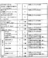
ここで、グループ所属端末群情報記憶部D1が記憶するグループ所属端末群情報のより具体的な例について図3を参照して説明する。図3は、グループ所属端末群情報の一例を表す図である。 Here, a more specific example of the group belonging terminal group information stored in the group belonging terminal group information storage unit D1 will be described with reference to FIG. FIG. 3 is a diagram illustrating an example of group belonging terminal group information.
図3に表されるように、グループ所属端末群情報は、グループ所属端末群情報データベーステーブル及び端末情報テーブルの2つのテーブルを含む。 As shown in FIG. 3, the group belonging terminal group information includes two tables, a group belonging terminal group information database table and a terminal information table.
ここで、グループ所属端末群情報データベーステーブルは、グループIDをキーに検索されるテーブルである。グループ所属端末群情報データベーステーブルには、それぞれのグループIDに対応したそれぞれのグループに所属している所属端末を識別するための端末IDが格納されている。何れかのグループIDをキーとして検索することにより、このグループIDに対応するグループに所属している端末の端末IDを抽出することができる。また、各グループに所属している何れの端末が現在送信権を取得しているのかも抽出することができる。なお、送信権とは、RTPパケットの送信元となる権利である。送信権を取得している端末が、1対多の通信における、1となる。 Here, the group belonging terminal group information database table is a table searched with the group ID as a key. In the group belonging terminal group information database table, terminal IDs for identifying belonging terminals belonging to each group corresponding to each group ID are stored. By searching using any of the group IDs as a key, the terminal IDs of the terminals belonging to the group corresponding to this group ID can be extracted. It is also possible to extract which terminal belonging to each group is currently acquiring the transmission right. It should be noted that the transmission right is a right that is a transmission source of the RTP packet. The terminal that has acquired the transmission right becomes 1 in one-to-many communication.
ここで、送信元端末が所属しているグループに送信権を得ている端末が有るか否かを検索する方法について説明する。 Here, a method for searching whether or not there is a terminal that has the transmission right in the group to which the transmission source terminal belongs will be described.
例えば、送信元端末IDを検索キーとして端末情報テーブルを検索することにより、送信元端末S1が所属するグループのグループIDを取得する。そして、取得したグループIDで一意に識別されるグループ内に、送信権を取得している端末が有るか否かを確認する。このために、送信権の取得又は現在送信権を得ている端末が有るか否か、有るとすればどの端末であるか、という情報を、送信権の取得及び開放が行われるたびに、グループIDと紐付けて図3のように記憶しておく。 For example, the group ID of the group to which the transmission source terminal S1 belongs is acquired by searching the terminal information table using the transmission source terminal ID as a search key. Then, it is confirmed whether or not there is a terminal that has acquired the transmission right in the group that is uniquely identified by the acquired group ID. For this purpose, information about whether or not there is a terminal that has acquired the transmission right or currently has the transmission right and, if so, which terminal is the group is added to the group every time the transmission right is acquired and released. It is associated with the ID and stored as shown in FIG.
また、図3のようにグループIDと現在送信権を得ている端末を紐付けて記憶しておくのではなくて、送信権の取得及び開放が行われるたびに、現在送信権を得ている端末であるか否かを表す情報を各端末IDに紐づけておくようにしても良い。この場合には、送信元端末S1が所属するグループのグループIDを検索キーとして所属端末群情報データベーステーブルを検索することにより、送信元端末S1が所属するグループに所属している端末の端末IDを全て抽出する。そして、抽出した端末IDのそれぞれに紐付いている現在送信権を得ている端末であるか否かを表す情報を参照することにより、現在送信権を得ている端末が有るか否かを判定する。こうすることによっても、送信元端末S1が所属している所属グループで送信権を取得している端末が有るか否かを確認することができる。 Further, as shown in FIG. 3, the group ID and the terminal currently having the transmission right are not stored in association with each other, but the transmission right is currently obtained each time the transmission right is acquired and released. Information indicating whether the terminal is a terminal may be associated with each terminal ID. In this case, the terminal ID of the terminal belonging to the group to which the source terminal S1 belongs is searched by searching the belonging terminal group information database table using the group ID of the group to which the source terminal S1 belongs as a search key. Extract all. Then, it is determined whether or not there is a terminal that currently has the transmission right by referring to the information that is associated with each of the extracted terminal IDs and that indicates whether or not the terminal currently has the transmission right. .. This also makes it possible to confirm whether or not there is a terminal that has acquired the transmission right in the belonging group to which the transmission source terminal S1 belongs.
なお、本実施形態では、音声通信を行なうことを想定していることから、送信権ではなく、送話権と表現しても良いが、本実施形態の適用範囲は必ずしも音声通信に限定されないことから、本明細書では、送信権との表現を用いる。また、本実施形態において、1つのグループに含まれる端末の台数に特に制限はない。 In addition, in the present embodiment, since it is assumed that voice communication is performed, it may be expressed as a transmission right instead of a transmission right, but the application range of the present embodiment is not necessarily limited to voice communication. Therefore, in this specification, the expression of transmission right is used. Further, in the present embodiment, there is no particular limitation on the number of terminals included in one group.
他方、端末情報テーブルは、端末IDをキーに検索されるテーブルである。端末情報テーブルには、それぞれの端末IDにより識別される各端末に関しての情報が格納されている。具体的には、端末のIPアドレス、特権者情報、選択可能グループ情報、選択グループ情報、死活状態が格納されている。 On the other hand, the terminal information table is a table searched with the terminal ID as a key. The terminal information table stores information about each terminal identified by each terminal ID. Specifically, the IP address of the terminal, privileged user information, selectable group information, selected group information, and alive status are stored.
端末のIPアドレスは、各端末に割り当てられているIPアドレスである。 The IP address of the terminal is the IP address assigned to each terminal.
また、特権者情報とは、各端末が特権者として設定されているか否かを表す情報である。端末が特権者として設定されている場合には、値をTrueとし、端末が特権者として設定されていない場合には、値をfalseとする。特権者が具体的にどのようなものであるのかは、第1の変形例の説明として後述する。 The privileged person information is information indicating whether or not each terminal is set as a privileged person. If the terminal is set as a privileged person, the value is True, and if the terminal is not set as a privileged person, the value is false. What the privileged person is specifically will be described later as a description of the first modification.
選択可能グループ情報とは、各端末が、RTPパケットの送信先のグループとして選択できるグループが、どのグループであるかを表す情報である。選択可能グループ情報は、例えばビットマップインデックスにより管理されるようにすると良い。具体的には、配信システム100に含まれる全てのグループ毎に行を設け、各端末がそのグループを選択できるのであれば、値を「1」とし、各端末がそのグループを選択できるのであれば、値を「0」とするように管理する。送信権取得制御部M4や、RTPパケット複製部M5は、このビットマップインデックスを使用して検索することにより、各端末が選択できるグループであるか否かを判断することができる。 The selectable group information is information indicating which group each terminal can select as the destination group of the RTP packet. The selectable group information may be managed by a bitmap index, for example. Specifically, if a line is provided for every group included in the distribution system 100 and each terminal can select that group, the value is set to "1" and each terminal can select that group. , So that the value is set to “0”. The transmission right acquisition control unit M4 and the RTP packet duplication unit M5 can determine whether each terminal is a selectable group by performing a search using this bitmap index.
選択グループ情報は、各端末を使用するユーザが、選択したグループである。ここで、選択可能グループが1つしかない端末があったとすれば、その端末は、ユーザによる選択をされるまでもなく、その1つの選択可能グループが、そのまま選択グループとなる。一方で、選択可能グループが複数ある端末であれば、その端末のユーザは、この複数のグループのなかから送信先とするグループを選択する。つまり、この選択されたグループが選択グループとなる。そして、選択グループに含まれる各端末がRTPパケットの送信先となる。 The selected group information is the group selected by the user who uses each terminal. Here, if there is a terminal having only one selectable group, that one selectable group becomes the selected group as it is, without the terminal being selected by the user. On the other hand, if the terminal has a plurality of selectable groups, the user of the terminal selects a group to be a transmission destination from the plurality of groups. That is, this selected group becomes the selected group. Then, each terminal included in the selected group becomes the destination of the RTP packet.
死活状態は、現在その端末が通信可能な状態にあるか否かを表す情報である。端末が通信可能な状態であれば、値をActiveとする。一方で、端末が無線通信可能な範囲の圏外に在圏していたり、端末がバッテリ切れをおこしていたりするような状態であって、端末が通信できない状態であれば値をnonとする。 The alive state is information indicating whether the terminal is currently in a communicable state. If the terminal is in a communicable state, the value is set to Active. On the other hand, the value is set to non if the terminal is out of the range where wireless communication is possible or the terminal is running out of battery and the terminal cannot communicate.
これらの情報の内、端末ID、IPアドレス、特権者情報及び選択可能グループ情報は、例えば予め配信装置E1を管理する保守者が入力しておくことで静的に設定される。 Of these information, the terminal ID, the IP address, the privileged person information, and the selectable group information are statically set by, for example, the maintenance person who manages the distribution device E1 in advance.
また、これらの情報の内、選択グループ情報は、例えば端末のグループ選択操作で動的に設定されるものとする。 Further, among these pieces of information, the selected group information is dynamically set by, for example, a group selection operation of the terminal.
更に、これらの情報の内、死活状態は、例えば端末と配信装置又は端末とは別途用意する死活監視サーバが各端末の死活監視を行い、この死活監視の結果を配信装置E1との間でやり取りすることで動的に設定されることとする。 In addition, the alive status of these pieces of information is, for example, a terminal and a distribution device, or a life and death monitoring server prepared separately from the terminal performs life and death monitoring of each terminal, and exchanges the result of the life and death monitoring with the distribution device E1. By doing so, it will be dynamically set.
また、これらの情報を他の情報で置き換えたり、これらの情報以外の他の情報を追加したりするようにしても良い。 Further, these pieces of information may be replaced with other information, or information other than these pieces of information may be added.
例えば、ユーザが端末使用時に端末を認証するときに、ユーザにユーザIDを入力させるようにする。そして、特権者情報をユーザIDに関連付けた情報とするようにしても良い。つまり、端末ID毎に特権者情報を紐付けるのではなく、ユーザID毎に特権者情報を紐付けるようにしても良い。これにより、同じ端末であっても、使用するユーザにより、特権者情報の有無を異ならせることができる。 For example, when the user authenticates the terminal when using the terminal, the user is prompted to input the user ID. Then, the privileged user information may be associated with the user ID. That is, instead of associating the privileged person information with each terminal ID, the privileged person information may be associated with each user ID. As a result, even with the same terminal, the presence or absence of privileged user information can be changed depending on the user who uses the terminal.
他にも、例えば盗難・亡失対策用に、盗難された端末又は亡失した端末を使用不可とするための盗難・亡失情報を設けてもよい。そして、盗難・亡失情報がfalseであれば、端末を通常通りに使用可能とする。一方で、ユーザから端末の盗難又は亡失の届けを受けた配信装置E1の保守者が、盗難された又は亡失した端末の盗難・亡失情報をtrueと設定した場合には、この盗難された又は亡失した端末を使用不可とするようにしても良い。 In addition, stolen/lost information may be provided for disabling a stolen terminal or a lost terminal, for example, as a measure against theft/lost. If the theft/lost information is false, the terminal can be used normally. On the other hand, if the maintainer of the distribution device E1 that has received the report of the theft or loss of the terminal from the user sets the theft/lost information of the stolen or lost terminal to true, the stolen or lost information is set. You may make it impossible to use the terminal.
次に、送信元端末S1から送信されるRTPパケットや、RTPパケット複製部M5が複製することにより作成するRTPパケットのフォーマットについて図4−1及び図4−2を参照して説明する。かかるフォーマットは基本的にRTPに準拠するものである。 Next, the format of the RTP packet transmitted from the transmission source terminal S1 and the format of the RTP packet created by being duplicated by the RTP packet duplicating unit M5 will be described with reference to FIGS. 4-1 and 4-2. Such a format basically complies with RTP.
しかしながら、「信号送信時の設定内容」に〈書き換え〉と記載されている項目については、RTPパケット複製部M5がRTPパケットを複製する際に書き換えられる。具体的な、書き換え内容については後述する。 However, the item described as "rewrite" in the "setting contents at the time of signal transmission" is rewritten when the RTP packet duplication unit M5 duplicates the RTP packet. The specific rewriting content will be described later.
また、「信号送信時の設定内容」に[受信したパケットのまま]と記載されている項目については、RTPパケット複製部M5がRTPパケットを複製する際に書き換えられることはなく、送信元端末S1から受信したRTPパケットの値のまま複製される。 In addition, items described as “as received packet” in the “setting contents at the time of signal transmission” are not rewritten when the RTP packet duplication unit M5 duplicates the RTP packet, and the transmission source terminal S1 The value of the RTP packet received from is copied as it is.
更に、「信号送信時の設定内容」に[受信したパケットのまま]及び〈本実施形態特有の情報〉と記載されている項目については、送信元端末S1から受信したRTPパケットの値のまま複製され、且つ、本実施形態特有の方法で利用される。本実施形態特有の方法で利用としては、例えば、送信元端末S1は、RTPパケットのSSRC(送信元ID)フィールドに、送信元端末S1を一意に識別するためのIDを格納して送信する、といった利用方法である。 Further, as for the items described as "Received packet as it is" and "Information peculiar to this embodiment" in "Setting contents at the time of signal transmission", the value of the RTP packet received from the source terminal S1 is copied as it is. And is used in a method peculiar to this embodiment. For use in the method peculiar to this embodiment, for example, the transmission source terminal S1 stores an ID for uniquely identifying the transmission source terminal S1 in the SSRC (transmission source ID) field of the RTP packet, and transmits it. It is a usage method such as.
更に、RTP拡張ヘッダを利用することも考えられる。そのため、図5では、RTP拡張ヘッダも使用する場合の例を記載している。具体的には、RTP拡張ヘッダの〈本実施形態特有の情報(例)〉と記載されている項目である。また、図2においてもRTP拡張ヘッダ制御部M8−4を記載している。 Further, it is possible to use the RTP extension header. Therefore, FIG. 5 shows an example in which the RTP extension header is also used. Specifically, it is an item described as <information specific to this embodiment (example)> of the RTP extension header. Further, also in FIG. 2, the RTP extension header control unit M8-4 is described.
しかしながら、RTP拡張ヘッダを使用することは必須ではない。そこで、本実施形態の説明では、RTP拡張ヘッダは使用しないケースについて説明する。そして、RTP拡張ヘッダを使用するケースについては、本実施形態の変形例として後述する。なお、RTP拡張ヘッダは使用しないケースの場合には、RTP拡張ヘッダ制御部M8−4を省略することができる。
[動作の説明]
次に、図5のフローチャート等を参照して、本実施形態における配信装置E1の配信時の動作について詳細に説明する。なお、図5は配信装置E1の基本的動作を表すフローチャートである。However, it is not mandatory to use the RTP extension header. Therefore, in the description of the present embodiment, a case where the RTP extension header is not used will be described. The case of using the RTP extension header will be described later as a modified example of this embodiment. If the RTP extension header is not used, the RTP extension header control unit M8-4 can be omitted.
[Description of operation]
Next, the distribution operation of the distribution device E1 in this embodiment will be described in detail with reference to the flowchart of FIG. Note that FIG. 5 is a flowchart showing the basic operation of the distribution device E1.
まず、送信元端末S1が、ユーザからのプッシュオン操作を受け付ける。プッシュオン操作を受け付けた送信元端末S1は、配信装置E1に対して、RTPパケットを送信する。そして、配信装置E1は、送信元端末S1が送信したRTPパケットをRTPパケット受信部M1によって受信する(ステップS11)。 First, the transmission source terminal S1 receives a push-on operation from the user. The transmission source terminal S1 that has received the push-on operation transmits an RTP packet to the distribution device E1. Then, the distribution device E1 receives the RTP packet transmitted by the transmission source terminal S1 by the RTP packet receiving unit M1 (step S11).
なお、本明細書では、送話を開始するために、送信権取得要求するため操作を上記のように「プッシュオン操作」と表現する。また、これとは逆に送話を終了するために送信権開放要求するための操作を「プッシュオフ操作」と表現する。これは、「押して話す」という本来の「プッシュ・ツー・トーク」の語源に合わせた表現である。 In this specification, the operation for making a transmission right acquisition request in order to start transmission is expressed as a “push-on operation” as described above. On the contrary, the operation for making a transmission right release request for ending the transmission is referred to as “push-off operation”. This is an expression tailored to the original etymology of "push to talk," which is "push to talk."
実際の操作の受け付け方としては、例えば送信元端末S1に接続する外部の送話ボタンを設け、外部の送話ボタンを押した時点で送信権取得要求を意味し(つまり、プッシュオン操作が行われたと判断し)、押したままの間は送話中とし、放した時点で送信権開放要求を意味する(つまり、プッシュオフ操作が行われたと判断する)、というように語源通りにしてもよい。 As a method of accepting an actual operation, for example, an external transmission button connected to the transmission source terminal S1 is provided, and when the external transmission button is pressed, a transmission right acquisition request is meant (that is, a push-on operation is performed. It is determined that the transmission right was released, and the transmission was started while the button was being held, and the transmission right release request was meant when the button was released (that is, the push-off operation was determined). Good.
しかしながら、必ずしも語源通りにする必要はなく、送話中に「押したままとする」という操作を要さないようにしても良い。例えば、端末上のディスプレイ上に表示した「送信権未取得状態」というアイコンに触れたら送信権取得要求を意味し(つまり、プッシュオン操作が行われたと判断し)、その後、何れのアイコンも触れられないのならば、送話中とし、端末上のディスプレイ上に表示した「送信権取得状態」というアイコンに触れたら送信権開放要求を意味する(つまり、プッシュオフ操作が行われたと判断する)、というようにしても良い。 However, it is not always necessary to follow the etymology, and the operation of “pressing and holding” during transmission may be unnecessary. For example, if you touch the icon of "state not acquired transmission right" displayed on the display on the terminal, it means a request to acquire transmission right (that is, it is determined that a push-on operation was performed), and then touch any icon. If it is not possible, it is assumed that the call is in progress, and touching the icon "acquisition of transmission right" displayed on the display on the terminal means a request to release the transmission right (that is, it is determined that a push-off operation has been performed). , May be used.
次に、配信装置E1の受信RTPパケット記憶部M2が、RTPパケット受信部M1が受信したRTPパケットを記憶する(ステップS12)。 Next, the reception RTP packet storage unit M2 of the distribution device E1 stores the RTP packet received by the RTP packet reception unit M1 (step S12).
ここで、RTPパケット受信部M1が受信したRTPパケットが配信中の(すなわち、現在送話中の)送信元端末が送信したRTPパケットであるか否かを判定する(ステップS13)。例えば、RTPパケット受信部M1が送信権取得制御部M4から、現在送信権を得ている端末のIPアドレスを取得しておく。そして、RTPパケット受信部M1が受信したRTPパケットの送信元IPアドレスが、現在送話権を得て、配信中の(すなわち、現在送話中の)送信元端末のIPアドレスと同一であるか否かに基づいて判定をする。 Here, it is determined whether or not the RTP packet received by the RTP packet receiving unit M1 is the RTP packet transmitted by the source terminal being delivered (that is, currently transmitting) (step S13). For example, the RTP packet reception unit M1 acquires the IP address of the terminal currently having the transmission right from the transmission right acquisition control unit M4. Then, is the transmission source IP address of the RTP packet received by the RTP packet reception unit M1 the same as the IP address of the transmission source terminal that is currently delivering the transmission right (that is, currently transmitting)? Make a decision based on whether or not.
RTPパケット受信部M1が受信したRTPパケットが、配信中の送信元端末が送信したものであれば(ステップS13においてYes)ステップS18の処理を行なうために、RTPパケットをRTPパケット複製部M5に渡す。なお、一般的な技術であることから詳細な説明は省略するが、ジッタバッファの制御等の、パケット通信における一般的な処理も受信RTPパケット記憶部M2で行う。 If the RTP packet received by the RTP packet receiving unit M1 is transmitted by the source terminal being delivered (Yes in step S13), the RTP packet is passed to the RTP packet copying unit M5 to perform the process of step S18. .. Although the detailed description is omitted because it is a general technique, the reception RTP packet storage unit M2 also performs general processing in packet communication such as control of a jitter buffer.
一方で、RTPパケット受信部M1が受信したRTPパケットが、配信中の送信元端末が送信したものでなく、他の端末が送信したものであれば(ステップS13においてNo)送信元端末ID制御部M3に処理を渡し、ステップS14に進む。 On the other hand, if the RTP packet received by the RTP packet receiving unit M1 is not sent by the sending source terminal being delivered but is sent by another terminal (No in step S13), the sending source terminal ID control unit The process is passed to M3, and the process proceeds to step S14.
ステップS14において、送信元端末ID制御部M3は、RTPパケットのSSRC(送信元ID)フィールドから送信元端末IDを抽出する。そして、送信元端末ID制御部M3は、この抽出した送信元端末IDを送信権取得制御部M4に出力し、送信権取得制御部M4に処理を渡し、ステップS15に進む。 In step S14, the transmission source terminal ID control unit M3 extracts the transmission source terminal ID from the SSRC (transmission source ID) field of the RTP packet. Then, the transmission source terminal ID control unit M3 outputs the extracted transmission source terminal ID to the transmission right acquisition control unit M4, passes the process to the transmission right acquisition control unit M4, and proceeds to step S15.
ステップS15において、送信権取得制御部M4は、送信元端末ID制御部M3から受信した送信元端末IDを検索キーとしてグループ所属端末群情報記憶部D1に記憶された端末情報テーブルを検索する。そして、端末情報テーブル内送信元端末S1の選択グループを参照することにより、送信元端末S1が所属している所属グループのグループIDを求める。 In step S15, the transmission right acquisition control unit M4 searches the terminal information table stored in the group belonging terminal group information storage unit D1 using the transmission source terminal ID received from the transmission source terminal ID control unit M3 as a search key. Then, the group ID of the belonging group to which the transmission source terminal S1 belongs is obtained by referring to the selected group of the transmission source terminal S1 in the terminal information table.
更に、送信権取得制御部M4は、このグループIDを検索キーとしてグループ所属端末群情報記憶部D1に記憶されたグループ所属端末群情報データベーステーブルを検索する。そして、送信元端末S1が所属している所属グループで送信権を取得している端末が有るか否かを確認する(ステップS15)。 Further, the transmission right acquisition control unit M4 searches the group belonging terminal group information database table stored in the group belonging terminal group information storage unit D1 using this group ID as a search key. Then, it is confirmed whether or not there is a terminal that has acquired the transmission right in the belonging group to which the transmission source terminal S1 belongs (step S15).
ステップS15における確認の結果、送信元端末S1が所属するグループに送信権を取得している端末がなければ(ステップS15においてNo)、送信元端末S1に送信権を与える。そして、送信元端末S1に送信権を与えた場合は、RTPパケットをRTPパケット複製部M5に渡す(ステップS16)。また、グループ所属端末群情報データベーステーブルの送信権取得端末の項目を更新する。この場合に、送信元端末S1に送信権が与えられた旨を、送信元端末S1に対して通知してもよい。 As a result of the confirmation in step S15, if there is no terminal that has acquired the transmission right in the group to which the transmission source terminal S1 belongs (No in step S15), the transmission right is given to the transmission source terminal S1. Then, when the transmission right is given to the transmission source terminal S1, the RTP packet is passed to the RTP packet copying unit M5 (step S16). Also, the item of the transmission right acquisition terminal in the group belonging terminal group information database table is updated. In this case, the transmission source terminal S1 may be notified that the transmission right has been given to the transmission source terminal S1.
ステップS15における確認の結果、送信元端末S1以外の端末が送信権を取得している場合には(ステップS15においてYes)、送信元端末S1に送信権を与えず、当該RTPパケットを破棄する(ステップS17)。また、送信元端末S1に送信権が与えられなかった旨を、送信元端末S1に対して通知してもよい。 As a result of the confirmation in step S15, when a terminal other than the transmission source terminal S1 has acquired the transmission right (Yes in step S15), the transmission right is not given to the transmission source terminal S1 and the RTP packet is discarded ( Step S17). Further, the transmission source terminal S1 may be notified that the transmission right has not been given to the transmission source terminal S1.
送信元端末S1から送信されたRTPパケットが、RTPパケット複製部M5に渡された場合は(ステップS13においてYes、又はステップS15においてNo及びステップS16)、グループ所属端末群情報記憶部D1の情報に基づいて送信先送信元端末S1が所属する所属グループの各端末を特定する。そして、特定した各端末にRTPパケットを配信するために、RTPパケット複製部M5は、各端末宛にRTPパケットを複製する。また、RTPパケット複製部M5は、複製したRTPパケットを送信RTPパケット記憶部M6に渡す(ステップS18)。 When the RTP packet transmitted from the transmission source terminal S1 is passed to the RTP packet duplication unit M5 (Yes in step S13, or No in step S15 and step S16), the information in the group belonging terminal group information storage unit D1 is recorded. Based on this, each terminal of the belonging group to which the destination transmission source terminal S1 belongs is specified. Then, in order to distribute the RTP packet to each specified terminal, the RTP packet copying unit M5 copies the RTP packet to each terminal. Further, the RTP packet copying unit M5 transfers the copied RTP packet to the transmission RTP packet storage unit M6 (step S18).
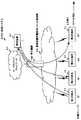
ここで、RTPパケットの送信先について図6を参照して説明する。図6に表される第1の端末T1がプッシュ操作を受け付けた送信元端末S1に相当する。よって、第1の端末T1から配信装置E1に対してRTPパケットが送信される。 Here, the destination of the RTP packet will be described with reference to FIG. The first terminal T1 shown in FIG. 6 corresponds to the transmission source terminal S1 that has received the push operation. Therefore, the RTP packet is transmitted from the first terminal T1 to the distribution device E1.
また、第1の端末T1はグループG1に所属する。そのため、第1の端末T1と同じグループG1に所属する第3の端末T3、第nの端末Tn等にはRTPパケットが配信される。一方で、第1の端末T1と異なるグループに所属する第3の端末T3等には配信されない。 The first terminal T1 belongs to the group G1. Therefore, the RTP packet is delivered to the third terminal T3, the nth terminal Tn, and the like belonging to the same group G1 as the first terminal T1. On the other hand, it is not distributed to the third terminal T3 and the like belonging to a group different from the first terminal T1.
このように配信先が決定される理由について説明する。それは、グループ所属端末群情報記憶部D1に、グループG1に所属する端末の情報として、第1の端末T1、第3の端末T3及び第nの端末Tn等の端末ID、並びに、これら端末IDのそれぞれに関連付いたIPアドレスの情報が、記憶されているからである。また、グループG2に所属する端末の情報として、第2の端末T2等の端末ID、並びに、第2の端末T2等の端末IDのそれぞれに関連付いたIPアドレスの情報が記憶されているからである。そして、RTPパケット複製部M5が、グループ所属端末群情報記憶部D1に記憶されているこれらの情報に基づいてRTPの複製及び配信先を決めているからである。 The reason why the delivery destination is determined in this way will be described. It is stored in the group belonging terminal group information storage unit D1 as the information of the terminals belonging to the group G1 such as the terminal IDs of the first terminal T1, the third terminal T3 and the nth terminal Tn, and these terminal IDs. This is because the information of the IP address associated with each is stored. Further, as the information of the terminals belonging to the group G2, the terminal IDs of the second terminal T2 and the like and the IP address information associated with each of the terminal IDs of the second terminal T2 and the like are stored. is there. Then, the RTP packet duplication unit M5 determines the duplication and delivery destination of the RTP based on these pieces of information stored in the group belonging terminal group information storage unit D1.
また、RTPパケット複製部M5は、送信元端末S1から受信したRTPパケットを単純に複製するだけではない。この点について、一般的な技術と比較しながら説明をする。 Further, the RTP packet copying unit M5 does not simply copy the RTP packet received from the transmission source terminal S1. This point will be described in comparison with general techniques.
まず、一般的な技術によって、イーサネット(登録商標)上を流れる一般的なIPパケットを転送する際の様子について図7を参照して説明する。なお、図中において凡例として説明しているように、イーサネット上を流れるパケットの上段部にはIPパケットに関する情報を表す。具体的には、情報として宛先IPアドレス及び送信元IPアドレスを表す。また、下段側にはイーサネット・フレームに関する情報を表す。具体的には、情報として宛先MACアドレス及び送信元MACアドレスを表す。 First, a state in which a general IP packet flowing on Ethernet (registered trademark) is transferred by a general technique will be described with reference to FIG. 7. Note that, as described as a legend in the figure, the upper part of the packet flowing on the Ethernet shows information about the IP packet. Specifically, a destination IP address and a source IP address are represented as information. Further, the lower side shows information about the Ethernet frame. Specifically, the destination MAC address and the source MAC address are represented as information.
イーサネット・フレームはルータで中継されるときに作り換えられる。そのとき、イーサネット・フレームに記載されている送信元のMACアドレスと宛先のMACアドレスが変わる。 The Ethernet frame is recreated when it is relayed by the router. At that time, the source MAC address and the destination MAC address described in the Ethernet frame change.
一方で、IPパケットには送信元IPアドレスと宛先IPアドレスが書いてあるが、これらはルータで中継されたとしても、宛先に届くまで変わらない。この点について、図7の例にあてはめて説明する。 On the other hand, the source IP address and the destination IP address are written in the IP packet, but even if these are relayed by the router, they do not change until they reach the destination. This point will be described with reference to the example of FIG. 7.
図7の例にあてはめると、パソコンAからサーバXにIPパケットが送られる場合、宛先MACアドレスは、ルータを中継する際に、ルータのネットワークセグメント1側のMACアドレスCからサーバXのMACアドレスEに変わる。また、パソコンAからサーバXにIPパケットが送られる場合、送信元MACアドレスは、パソコンAのMACアドレスAからルータのネットワークセグメント2側のMACアドレスDに変わる。しかし、IPアドレスは、宛先IPアドレスも送信元IPアドレスも変わらない。 In the example of FIG. 7, when an IP packet is sent from the personal computer A to the server X, the destination MAC address is from the MAC address C on the network segment 1 side of the router to the MAC address E of the server X when relaying the router. Change to When the personal computer A sends an IP packet to the server X, the source MAC address changes from the personal computer A's MAC address A to the router's
ここで仮に、配信装置E1が図7に表されるルータと同様の動作をすると考える。そうすると、配信装置E1は、MACアドレスは書き換えるが、IPアドレスは書き換えないことになる。 Here, it is assumed that the distribution device E1 operates similarly to the router shown in FIG. Then, the distribution device E1 rewrites the MAC address but does not rewrite the IP address.
しかし、配信装置E1から送信元IPアドレスを第1の端末T1のIPアドレスとして配信してしまうと問題が生じる可能性がある。例えば、第1の端末T1と第2の端末T2が同一のネットワークセグメントに存在していたとする。そして、配信装置E1は、これら2つの端末が存在するネットワークセグメントとは異なるネットワークセグメントに存在していたとする。 However, if the source IP address is delivered from the delivery device E1 as the IP address of the first terminal T1, a problem may occur. For example, assume that the first terminal T1 and the second terminal T2 are in the same network segment. Then, it is assumed that the distribution device E1 exists in a network segment different from the network segment in which these two terminals exist.
この場合、第1の端末T1のIPアドレスが送信元IPアドレスとなったIPパケットが、配信装置E1経由で、配信装置E1が存在するネットワークセグメントから第2の端末T2に届く。すると、第2の端末T2からみると、第1の端末T1が、第2の端末T2とは異なるネットワークセグメント(配信装置E1が存在するネットワークセグメント)に存在するかのように誤認する可能性がある。 In this case, an IP packet in which the IP address of the first terminal T1 is the source IP address reaches the second terminal T2 from the network segment in which the distribution device E1 exists via the distribution device E1. Then, from the perspective of the second terminal T2, there is a possibility that the first terminal T1 may be misidentified as if it exists in a network segment different from the second terminal T2 (a network segment in which the distribution device E1 exists). is there.
このため、IPヘッダ制御部M8−1は、送信元IPアドレスを送信元端末S1のIPアドレスから配信装置E1のIPアドレスに書き換え、更に、宛先IPアドレスを、配信装置E1のIPアドレスから各送信先端末のIPアドレスに書き換えて送信する。そして、RTPパケット複製部M5は、この書き換えられたIPアドレスを使用してRTPパケットを複製する。複製したRTPパケットは、配信するために、送信RTPパケット記憶部M6に渡される(ステップS18)。 Therefore, the IP header control unit M8-1 rewrites the transmission source IP address from the IP address of the transmission source terminal S1 to the IP address of the distribution device E1, and further transmits the destination IP address from the IP address of the distribution device E1 to each transmission. It is rewritten to the IP address of the destination terminal and transmitted. Then, the RTP packet duplication unit M5 duplicates the RTP packet using the rewritten IP address. The duplicated RTP packet is delivered to the transmission RTP packet storage unit M6 for distribution (step S18).
送信RTPパケット記憶部M6に格納されたRTPパケットは、RTPパケット送信部M7に渡され、実際に各送信先端末(第1の送信先端末R1乃至第nの送信先端末Rn)に配信する(ステップS19)。 The RTP packet stored in the transmission RTP packet storage unit M6 is passed to the RTP packet transmission unit M7 and actually delivered to each destination terminal (first destination terminal R1 to nth destination terminal Rn) ( Step S19).
以上説明した動作により、配信装置E1による配信が実現される。 By the operation described above, distribution by the distribution device E1 is realized.
なお、ステップS19でRTPパケット送信する方法として、2種類のRTPパケット送信方法を選択できる。 Two types of RTP packet transmission methods can be selected as the method for transmitting RTP packets in step S19.
1つ目のRTPパケット送信方法は、RTPパケットがRTPパケット記憶部M6に格納された時点で、直ちにRTPパケットを配信する方法(以降、「即時送信方式」と記載する)である。 The first RTP packet transmission method is a method of immediately delivering the RTP packet when the RTP packet is stored in the RTP packet storage unit M6 (hereinafter, referred to as "immediate transmission method").
もう1つ目の送信方法は、RTPパケット記憶部M6に格納されたRTPパケットを、一定周期で配信する方法(以降、「定間隔送信方式」と記載する)である。ここで、一定周期とは、任意の周期であって良いが、例えば、20ミリ秒とすることが考えられる。 The other transmission method is a method of delivering the RTP packet stored in the RTP packet storage unit M6 at a constant cycle (hereinafter, referred to as "constant interval transmission method"). Here, the fixed cycle may be an arbitrary cycle, but may be set to, for example, 20 milliseconds.
即時送信方式は、ネットワークのゆらぎが十分小さい場合に有利な方式である。即時送信方式では、直ちにRTPパケットが配信されることから通話の遅延をより少なくすることができる。 The immediate transmission method is an advantageous method when the fluctuation of the network is sufficiently small. In the immediate transmission method, since the RTP packet is immediately delivered, the call delay can be further reduced.
一方で、定間隔送信方式は、ネットワークのゆらぎが比較的大きい場合に有利な方式である。本実施形態では、端末同士が直接音声通信するのではなく、配信装置E1を介す。
そのため、上りのゆらぎと下りのゆらぎの両方のゆらぎの影響を受ける。そのため、一般的なジッタバッファではゆらぎを吸収しきれず、頻繁な音飛びにつながる可能性がある。
そこで、定間隔送信方式を採用することによって配信装置が一旦ゆらぎを吸収し、パケット送信間隔を一定間隔に整形して送信する。On the other hand, the fixed interval transmission method is an advantageous method when the fluctuation of the network is relatively large. In the present embodiment, the terminals do not directly perform voice communication with each other, but via the distribution device E1.
Therefore, it is affected by both upward and downward fluctuations. Therefore, a general jitter buffer may not be able to absorb the fluctuations, which may lead to frequent skipping.
Therefore, by adopting the constant interval transmission method, the distribution device once absorbs the fluctuation, shapes the packet transmission interval to a constant interval, and transmits.
ただし、ゆらぎの大きさに比例して、音声遅延が大きくなるという欠点もある。しかし、本実施形態のグループ一斉音声通信は、音声の片方向通信を前提としたものなので、通常の電話の同時双方向音声通信のようには遅延が問題とならない用途も多い。また、本実施形態のグループ一斉音声通信は、送話者がプッシュ操作をして切り替わるため、それまで蓄積した音声遅延が、送話者が切り替わるタイミングでリセットされる。つまり、本実施形態では、音声遅延がそれほど問題とならないことが多いので、ネットワークのゆらぎが比較的大きい場合には、定間隔送信方式を採用すると有益である。 However, there is also a drawback that the voice delay increases in proportion to the magnitude of the fluctuation. However, since the group simultaneous voice communication of the present embodiment is premised on the one-way communication of voice, there are many applications in which the delay does not pose a problem like the simultaneous two-way voice communication of a normal telephone. Further, in the group simultaneous voice communication of the present embodiment, the talker performs a push operation to switch the voice delay. Therefore, the voice delay accumulated up to that point is reset at the timing when the talker switches. In other words, in the present embodiment, the voice delay does not often become a problem, so when the fluctuation of the network is relatively large, it is useful to adopt the constant interval transmission method.
なお、上述した実施形態は、本発明の好適な実施形態ではあるが、上記実施形態のみに本発明の範囲を限定するものではなく、本発明の要旨を逸脱しない範囲において種々の変更を施した形態での実施が可能である。例えば、上記実施形態を、以下に説明する各変形例のように変形することが可能である。 The above-described embodiment is a preferred embodiment of the present invention, but the scope of the present invention is not limited to the above-described embodiment, and various changes are made without departing from the gist of the present invention. It can be implemented in the form. For example, the above-described embodiment can be modified as in each modification described below.
[第1の変形例]
次に、上述した実施形態を変形した例の1つである、第1の変形例について説明する。[First Modification]
Next, a first modified example, which is one of modified examples of the above-described embodiment, will be described.
上述した実施形態では、送信元端末S1は、RTPパケットのSSRC(送信元ID)フィールドに、送信元端末S1を一意に識別するためのIDを格納して送信するが、RTP拡張ヘッダについては使用しない例について説明した。 In the above-described embodiment, the transmission source terminal S1 stores the ID for uniquely identifying the transmission source terminal S1 in the SSRC (transmission source ID) field of the RTP packet and transmits it, but uses the RTP extension header. The example which does not do was explained.
第1の変形例ではRTP拡張ヘッダも使用する例について説明する。具体的には、図4−1及び図4−2を参照して説明したように、RTP拡張ヘッダに、送信元端末ID、グループID及び特権者情報等を格納するケースについて説明する。 In the first modification, an example in which an RTP extension header is also used will be described. Specifically, as described with reference to FIGS. 4A and 4B, a case will be described in which the sender terminal ID, the group ID, the privileged person information, and the like are stored in the RTP extension header.
なお、本変形例のように、RTP拡張ヘッダを使用すると、RTPパケットのサイズが増える。よって、RTPパケットを送受信するために、より多くのネットワーク帯域を必要とするというデメリットが発生する。しかし、このデメリットと引き換えに、RTP拡張ヘッダを使用すると、このデメリットと引き換えに、サーバの処理負荷を軽減したり、提供できるサービス機能が増したりするというメリットが発生する。そのため、これらのメリットを享受したい場合に、本変形例を採用すると有益である。 When the RTP extension header is used as in this modification, the size of the RTP packet increases. Therefore, there is a demerit that more network band is required for transmitting and receiving the RTP packet. However, if the RTP extension header is used in exchange for this demerit, there is an advantage in that the processing load on the server is reduced and the service functions that can be provided are increased in exchange for this demerit. Therefore, when it is desired to enjoy these merits, it is useful to adopt this modification.
RTP拡張ヘッダの利用方法としては、まず、上述の実施形態のように送信元端末IDをSSRCフィールドに載せるのではなく、RTP拡張ヘッダに送信元端末IDを載せることが考えられる。RTPに準拠した場合には、SSRCフィールドのサイズは32ビット(=4バイト)となる。そのため、送信元端末IDをSSRCに載せる場合には、送信元端末IDを4バイトで表さないとならないという制限がある。しかしながら、SSRCフィールドではなくRTP拡張ヘッダに送信元端末IDを載せることによって、この制限を撤廃することができる。 As a method of using the RTP extension header, first, it is conceivable to put the source terminal ID in the RTP extension header instead of putting the source terminal ID in the SSRC field as in the above embodiment. When conforming to RTP, the size of the SSRC field is 32 bits (=4 bytes). Therefore, when the transmission source terminal ID is placed on the SSRC, there is a limitation that the transmission source terminal ID must be represented by 4 bytes. However, this limitation can be removed by putting the source terminal ID in the RTP extension header instead of in the SSRC field.
このように4バイトの制限を撤廃することにより、端末IDに柔軟性を持たせることができる。具体例として、例えばMSISDN(国番号(81)+携帯電話番号から頭の「0」をとったもの)を使用することができる。MSISDNは、12桁であるが、バイナリ値で格納することによって、より少ないバイト数で載せることができる、MSISDNを端末IDとして使用することで、独自のIDを別途定義して使用する煩わしさや手間がなくなる。 By removing the 4-byte limitation in this way, the terminal ID can be made flexible. As a specific example, for example, MSISDN (country code (81)+mobile phone number with leading "0" removed) can be used. MSISDN has 12 digits, but it can be loaded with a smaller number of bytes by storing it as a binary value. By using MSISDN as a terminal ID, it is bothersome and troublesome to define and use a unique ID separately. Disappears.
また、RTP拡張ヘッダにグループIDを載せることも考えられる。このようにRTP拡張ヘッダにグループIDを載せることによって、RTP拡張ヘッダを参照すれば送信元端末S1の所属しているグループを識別することが可能となる。つまり、送信元端末S1の所属グループを求めるために、端末IDを検索キーとしたグループ所属情報端末群情報の検索を行わなくてもよくなる、というメリットが発生する。そして検索を行わなくてよい分、配信装置E1が他の処理に割ける処理能力が向上し、結果としてグループ内端末同時通信数等を増やすことができる。 It is also possible to put the group ID in the RTP extension header. By thus placing the group ID on the RTP extension header, it is possible to identify the group to which the transmission source terminal S1 belongs by referring to the RTP extension header. In other words, there is an advantage that it is not necessary to search the group affiliation information terminal group information using the terminal ID as a search key in order to obtain the affiliation group of the transmission source terminal S1. Since the search does not need to be performed, the processing capacity of the distribution device E1 that can be devoted to other processing is improved, and as a result, it is possible to increase the number of simultaneous intra-group terminal communication and the like.
更に、RTP拡張ヘッダに特権者情報を載せることも考えられる。このようにRTP拡張ヘッダに特権者情報を載せることによって、各端末のそれぞれを特権者とするか否かを設定することができる。 Further, it is possible to put privileged person information in the RTP extension header. In this way, by putting the privileged person information in the RTP extension header, it is possible to set whether or not each terminal is a privileged person.
ここで、特権者がどのようなものであるかについて説明する。プッシュ・ツー・トークグループ一斉音声通信では、無線での使用を前提としているため、送信者が送信権を取得したまま、無線圏外に移動してしまったり、端末のバッテリの残量がなくなり、端末がバッテリ切れに陥ってしまったりして、送信者が通信をできない状況になってしまうことが想定される。 Here, what kind of privileged person is will be described. Since push-to-talk group simultaneous voice communication is assumed to be used wirelessly, the sender may move out of the wireless range with the transmission right acquired, or the battery of the terminal may run out. It is assumed that the sender runs out of battery and the sender cannot communicate.
このような場合、送信権開放要求を配信装置E1等が受信することはできない。そのため、特定の端末が送信権を持ったままとなってしまう。このような状況の発生を避けるために、送信権開放要求の有無に関わらず、一定時間で送信権を強制解除する、という方法が考えられる。しかし、特定の送話者が長時間、音声情報を一方的に流したい用途も考えられ、この場合には、この一定時間で送信権を強制解除する、という方法では不都合が発生する。 In such a case, the distribution device E1 or the like cannot receive the transmission right release request. Therefore, the specific terminal remains to have the transmission right. In order to avoid such a situation, a method of forcibly canceling the transmission right within a certain period of time is conceivable regardless of the presence or absence of the transmission right release request. However, there may be an application in which a specific talker wants to unilaterally transmit voice information for a long time, and in this case, the method of forcibly canceling the transmission right at this fixed time causes inconvenience.
そこで、本変形例では、特権者を設ける。そして、送信権取得制御手順M4は、特権者からのプッシュ操作(送信権取得要求)を受けた場合は、他の端末が送信権を取得していたとしても、強制的に送信権を取得する。そして、取得した送信権を特権者の端末に与えて、かかる特権者の端末が送信したRTPパケットを配信対象とする。こうすることにより、特権者以外の端末が送信権を取得中に無線圏外に移動してしまったり、端末のバッテリ切れに陥ってしまったりしたような場合であっても他の端末間での通信を継続することが可能となる。 Therefore, in this modification, a privileged person is provided. Then, when the push operation (transmission right acquisition request) is received from the privileged person, the transmission right acquisition control procedure M4 forcibly acquires the transmission right even if another terminal has acquired the transmission right. .. Then, the acquired transmission right is given to the terminal of the privileged person, and the RTP packet transmitted by the terminal of the privileged person is targeted for distribution. By doing this, even if a terminal other than the privileged person moves out of the wireless range while acquiring the transmission right, or if the terminal's battery falls out, communication between other terminals It is possible to continue.
また、特権者の端末が送信権を取得中に無線圏外に移動してしまったり、端末のバッテリ切れに陥ってしまったりすることも想定される。そのため、同一グループの特権者を1台に限定することなく、複数台を特権者として設定してもよい。 It is also assumed that the terminal of the privileged person may move out of the wireless range while acquiring the transmission right, or the battery of the terminal may run out. Therefore, a plurality of privileged persons in the same group may be set as a privileged person without being limited to one.
更に、RTP拡張ヘッダに送話終了フラグを載せることも考えられる。このようにRTP拡張ヘッダに送話終了フラグを載せることによって、送信権解放要求を明示的に通知することができる。 Further, it is possible to put a transmission end flag in the RTP extension header. By thus placing the transmission end flag in the RTP extension header, the transmission right release request can be explicitly notified.
仮に、送話終了フラグを載せない場合、RTPパケットが一定時間受信されない場合には送話が終了したとみなし、送信権を開放することが考えられる。こうする場合、RTPパケットのネットワーク遅延をどこまで許すかによって、送話終了とみなすまでの時間が変わる。例えば、ネットワーク遅延が小さいことが予想されるような環境では、送話終了と判断するまでの時間を短くすることができるため、送話終了後、短時間で送話終了と判断することができる。しかしながら、ネットワーク遅延が大きくなることが予想される環境では、送話終了と判断するまでの時間を長くとる必要がある。なぜならば、一定時間RTPパケットが受信されない理由が、送信元からのRTPパケットの送信が終了したからなのか、送信元からのRTPパケットが遅延を受けていることから未だRTPパケットが到着していないのか、の何れなのかが区別できないからである。そのため、ネットワーク遅延が大きくなることが予想される環境では、送話終了してからしばらくしないと、送信先端末Rで送話終了を認識できなかったり、配信装置E1で送信権開放が行えなかったりする。 If the transmission end flag is not set and the RTP packet is not received for a certain period of time, it is considered that the transmission is completed and the transmission right is released. In this case, the time until the end of transmission is considered to change depending on how much the network delay of the RTP packet is allowed. For example, in an environment where network delay is expected to be small, it is possible to shorten the time until it is determined that transmission has ended, so it can be determined that transmission has ended in a short time after the end of transmission. .. However, in an environment where network delay is expected to be large, it is necessary to take a long time until it is determined that transmission has ended. The reason why the RTP packet is not received for a certain period of time is that the transmission of the RTP packet from the transmission source has ended, or because the RTP packet from the transmission source is delayed, the RTP packet has not arrived yet. This is because it is not possible to distinguish between Therefore, in an environment where network delay is expected to become large, the transmission end cannot be recognized by the destination terminal R or the transmission right cannot be released by the distribution device E1 until some time after the transmission ends. To do.
そこで、送信元端末S1がプッシュオフ操作を行ったタイミングで送信するRTPパケットのRTP拡張ヘッダに、送話終了を意味する送話終了フラグを載せる。加えて、また、送話終了フラグを含めて配信装置のRTPパケット複製部M5がRTPパケットを複製して受信端末に通知する。更に、配信装置E1及び受信端末が送話終了フラグを参照する。 Therefore, the transmission end flag indicating the end of the transmission is placed in the RTP extension header of the RTP packet transmitted at the timing when the transmission source terminal S1 performs the push-off operation. In addition, the RTP packet duplication unit M5 of the distribution device duplicates the RTP packet including the transmission end flag and notifies the receiving terminal. Further, the distribution device E1 and the receiving terminal refer to the transmission end flag.
このようにすることによって、配信装置E1及び受信端末は、送信元端末S1がプッシュオフ操作を行った後、直ちに送話終了を認識することができる。 By doing so, the distribution device E1 and the reception terminal can immediately recognize the end of transmission after the source terminal S1 performs the push-off operation.
[第2の変形例]
次に、上述した実施形態を変形した例の1つである、第2の変形例について説明する。
本変形例は、第1の変形例同様に、RTP拡張ヘッダを使用するものである。[Second Modification]
Next, a second modified example, which is one of the modified examples of the above-described embodiment, will be described.
This modified example uses the RTP extension header as in the first modified example.
まず、本変形例では、送信元端末S1の名称を送信先端末Rにて表示可能とする。そのために、配信装置E1が配信するRTPパケットのRTP拡張ヘッダに、送信元端末S1の端末名称情報を格納する。 First, in the present modification, the name of the transmission source terminal S1 can be displayed on the transmission destination terminal R. Therefore, the terminal name information of the transmission source terminal S1 is stored in the RTP extension header of the RTP packet distributed by the distribution device E1.
具体的には、配信装置E1の、端末情報テーブルにて送信元端末S1の端末IDと送信元端末S1の端末名称情報を紐付けて記憶しておく。 Specifically, in the terminal information table of the distribution device E1, the terminal ID of the transmission source terminal S1 and the terminal name information of the transmission source terminal S1 are stored in association with each other.
そして、RTP拡張ヘッダ制御部M8−4は、送信元端末S1から受信したRTPパケットに含まれる送信元端末S1の端末IDを検索キーにして端末情報テーブルを検索することにより、予め設定しておいた端末IDに関連付けた端末名称情報を取得する。そして、RTP拡張ヘッダ制御部M8−4は、取得した端末名称情報から送信元端末名称を求める。そして、配信装置E1は、送信者が変わった際の最初のRTPパケットのRTPパケットのRTP拡張ヘッダに、送信元端末名称を含めて配信する。 Then, the RTP extension header control unit M8-4 sets in advance by searching the terminal information table using the terminal ID of the transmission source terminal S1 included in the RTP packet received from the transmission source terminal S1 as a search key. The terminal name information associated with the existing terminal ID is acquired. Then, the RTP extension header control unit M8-4 obtains the source terminal name from the acquired terminal name information. Then, the distribution device E1 distributes the source terminal name in the RTP extension header of the RTP packet of the first RTP packet when the sender changes.
配信を受けた送信先端末Rでは、RTP拡張ヘッダを参照することにより、送信元端末S1の名称を知ることができ、この送信元端末S1の名称を送信先端末Rの表示部に表示することが可能となる。 The destination terminal R that has received the distribution can know the name of the source terminal S1 by referring to the RTP extension header, and display the name of the source terminal S1 on the display unit of the destination terminal R. Is possible.
次に、RTP拡張ヘッダに、送信者名称情報を格納するケースについて説明する。 Next, a case where the sender name information is stored in the RTP extension header will be described.
予め配信装置E1にユーザIDに関連付けたユーザ名称情報を設定しておく。
配信装置E1の、端末情報テーブルにてユーザIDと、このユーザIDに対応するユーザのユーザ名称情報を紐付けて記憶しておく。User name information associated with the user ID is set in advance in the distribution device E1.
In the terminal information table of the distribution device E1, the user ID and the user name information of the user corresponding to this user ID are stored in association with each other.
また、送信元端末S1を使用時に、送信元端末S1に使用者を識別することが可能なユーザIDを登録する。 Further, when the source terminal S1 is used, a user ID capable of identifying the user is registered in the source terminal S1.
そして、送信元端末S1は、RTPパケットのRTP拡張ヘッダに、送信元端末S1に登録されたユーザIDを付加して配信装置E1に通知する。 Then, the transmission source terminal S1 adds the user ID registered in the transmission source terminal S1 to the RTP extension header of the RTP packet and notifies the distribution device E1.
RTP拡張ヘッダ制御部M8−4は、送信元端末S1から受信したRTPパケットに含まれるユーザIDをキー検索キーにして端末情報テーブルを検索することにより、予め設定しておいたユーザIDに関連付けたユーザ名称情報取得し、取得したユーザ名称情報から送信者名称情報を求める。そして、送信者が変わった際の最初のRTPパケットのRTPパケットのRTP拡張ヘッダに、送信者名称を含めて配信する。 The RTP extension header control unit M8-4 uses the user ID included in the RTP packet received from the transmission source terminal S1 as a key search key to search the terminal information table to associate it with the preset user ID. User name information is acquired, and sender name information is obtained from the acquired user name information. Then, the sender name is included in the RTP extension header of the RTP packet of the first RTP packet when the sender is changed, and distribution is performed.
これによって、送信先端末Rで送信者の名称を表示することが可能となる。 This enables the destination terminal R to display the name of the sender.
配信を受けた送信先端末Rでは、RTP拡張ヘッダを参照することにより、送信者の名称を知ることができ、この送信元端末S1の名称を送信先端末Rの表示部に表示することが可能となる。 The destination terminal R that has received the distribution can know the name of the sender by referring to the RTP extension header, and the name of the source terminal S1 can be displayed on the display unit of the destination terminal R. Becomes
本変形例では、端末名称情報や送信者名称情報を送信先端末Rにて表示することができるのみならず、通信データ量の増加を最低限に抑え、必要音声通信帯域に与える影響を抑えることができる。その理由は、端末名称情報や送信者名称情報といった名称情報を、送信者が変わった際の最初のRTPパケットに限定してRTPパケットのRTP拡張ヘッダ含めて配信するからである。 In this modification, not only the terminal name information and the sender name information can be displayed on the destination terminal R, but also the increase of the communication data amount is minimized and the influence on the required voice communication band is suppressed. You can The reason is that the name information such as the terminal name information and the sender name information is limited to the first RTP packet when the sender is changed and is distributed including the RTP extension header of the RTP packet.
[第3の変形例]
次に、上述した実施形態を変形した例の1つである、第3の変形例について説明する。
本変形例は、第1の変形例同様に、RTP拡張ヘッダを使用するものであり、具体的にはRTP拡張ヘッダに、送信元端末S1の位置情報を格納する。位置情報は、送信元端末S1の位置を特定するための情報であれば良く、特に制限はないが、例えばGPS(Global Positioning System)により測位された座標を表す情報を位置情報として使用することができる。[Third Modification]
Next, a third modified example, which is one of modified examples of the above-described embodiment, will be described.
This modification uses an RTP extension header like the first modification, and specifically stores the location information of the source terminal S1 in the RTP extension header. The position information is not particularly limited as long as it is information for identifying the position of the transmission source terminal S1, and, for example, information indicating coordinates measured by GPS (Global Positioning System) may be used as the position information. it can.
まず、送信元端末S1がプッシュオン操作を受け付けると、送信者が変わって送信元端末S1が最初に送信するRTPパケットのRTP拡張ヘッダに送信元端末S1の位置情報(例えば、GPS情報等)を含めて、配信装置E1に対して送信する。 First, when the source terminal S1 accepts a push-on operation, the sender changes and the position information (eg, GPS information) of the source terminal S1 is added to the RTP extension header of the RTP packet that the source terminal S1 first transmits. Including, it transmits to the distribution apparatus E1.
RTP拡張ヘッダ制御部M8−4は、送信元端末S1から受信したRTPパケットに含まれる位置情報を抽出し、外部のサーバに通知したりする。これによって、外部サーバに送信元端末S1の位置(すなわち、送信者の位置)をログとして残したり、地図検索表示システムなどと連携して、送信元端末S1の位置(すなわち、送信者の位置)を地図上に表示したりするといった応用が可能となる。 The RTP extension header control unit M8-4 extracts the position information included in the RTP packet received from the transmission source terminal S1 and notifies the external server of the position information. Thereby, the position of the source terminal S1 (that is, the position of the sender) is left as a log in the external server, or the position of the source terminal S1 (that is, the position of the sender) is linked with a map search display system or the like. Applications such as displaying on a map are possible.
また、RTPパケット複製部M5が、位置情報を含めたままRTPパケットを複製して配信することにより、受信端末Rに送信元端末S1の位置(すなわち、送信者の位置)を知らせるようにしても良い。これによって、受信端末のディスプレイに送信者の位置を表示したりするといった応用が可能となる。 In addition, the RTP packet duplication unit M5 duplicates and distributes the RTP packet while including the position information to notify the receiving terminal R of the position of the source terminal S1 (that is, the position of the sender). good. This enables applications such as displaying the position of the sender on the display of the receiving terminal.
なお、送信する全てのRTPパケットのRTP拡張ヘッダに、送信元端末S1の位置情報(例えば、GPS情報等)を付加して配信装置E1に通知するようにしても良い。しかし、必ずしも全てのRTPパケットのRTP拡張ヘッダに位置情報(例えば、GPS情報等)を付加する必要はない。 The position information (eg, GPS information) of the transmission source terminal S1 may be added to the RTP extension headers of all the RTP packets to be transmitted to notify the distribution device E1. However, it is not always necessary to add position information (eg GPS information) to the RTP extension headers of all RTP packets.
例えば位置情報(例えば、GPS情報等)を付加するのは、送信元端末S1が送信権取得操作を行う毎に最初のRTPパケットのみに限定しても良い。他にも、送信元端末S1が送信権を得ている状態で予め設定した一定周期のタイミングに限定しても良い。他にも、送信元端末S1が送信権を得ている状態で、端末の位置が予め設定した距離以上を移動する毎のタイミングに限定しても良い。他にも、送信元端末S1が送信権を得ている状態で、ユーザから位置情報送信操作を受け付けたタイミングに限定しても良い。 For example, the position information (for example, GPS information) may be added only to the first RTP packet every time the transmission source terminal S1 performs the transmission right acquisition operation. In addition, the timing may be limited to a preset fixed cycle while the transmission source terminal S1 has the transmission right. Alternatively, the timing may be limited to every time the position of the terminal moves over a preset distance while the source terminal S1 has the transmission right. Alternatively, it may be limited to the timing at which the position information transmission operation is received from the user while the transmission source terminal S1 has the transmission right.
このように、位置情報(例えば、GPS情報等)を付加するRTPパケットを限定することによって、通信データ量の増加を最低限に抑え、必要音声通信帯域に与える影響を抑えることが可能となる。 As described above, by limiting the RTP packet to which the position information (for example, GPS information) is added, the increase of the communication data amount can be suppressed to the minimum and the influence on the required voice communication band can be suppressed.
[第4の変形例]
次に、上述した実施形態を変形した例の1つである、第4の変形例について説明する。[Fourth Modification]
Next, a fourth modified example, which is one of the modified examples of the above-described embodiment, will be described.
本変形例では、RTP拡張ヘッダに載せていた送信元端末S1が所属又は選択したグループの情報を、UDPの宛先ポート番号及び送信元ポート番号の一方又は他方に置き換えて、送信元端末S1がRTPパケットを生成する。そして、生成したRTPパケットを、送信元端末S1が配信装置E1に対して送信する。 In this modification, the source terminal S1 replaces the information on the group to which the source terminal S1 belongs or is selected in the RTP extension header with one or the other of the UDP destination port number and the source port number, and the source terminal S1 transmits the RTP. Generate a packet. Then, the transmission source terminal S1 transmits the generated RTP packet to the distribution device E1.
そして、配信装置E1のUDPヘッダ制御部M8−2は、受信したRTPパケットのUDPの宛先ポート番号又は送信元ポート番号から送信元端末S1が所属又は選択したグループ番号を識別する。 Then, the UDP header control unit M8-2 of the distribution device E1 identifies the group number to which the source terminal S1 belongs or is selected from the UDP destination port number or source port number of the received RTP packet.
また、このような構成にするのではなく、以下のような構成にしても良い。 Further, instead of having such a configuration, the following configuration may be adopted.
送信元端末S1が、送信元端末S1が所属又は選択したグループの情報を、例えばRTP拡張ヘッダに載せてRTPパケットを生成する。そして、生成したRTPパケットを、送信元端末S1が配信装置E1に対して送信する。 The transmission source terminal S1 puts information on the group to which the transmission source terminal S1 belongs or is selected, for example, on an RTP extension header to generate an RTP packet. Then, the transmission source terminal S1 transmits the generated RTP packet to the distribution device E1.
そして、配信装置E1のUDPヘッダ制御部M8−2は、受信したグループの情報を、RTPパケットのUDPの宛先ポート番号及び送信元ポート番号の一方又は他方に置き換える。 Then, the UDP header control unit M8-2 of the distribution device E1 replaces the received group information with one or the other of the UDP destination port number and the transmission source port number of the RTP packet.
送信元端末S1が所属又は選択したグループの情報によって、RTPパケットのUDPの宛先ポート番号及び送信元ポート番号の一方又は他方を分ける。これにより、複数グループのRTPパケットを同一の受信端末に複数送ることができるから、受信端末側が複数グループの受話の同時再生に対応するような応用を実現することができる。 One or the other of the UDP destination port number and the source port number of the RTP packet is divided according to the information of the group to which the source terminal S1 belongs or is selected. As a result, a plurality of RTP packets of a plurality of groups can be sent to the same receiving terminal, so that it is possible to realize an application in which the receiving terminal side supports simultaneous reproduction of the receptions of a plurality of groups.
以上説明した実施形態及び各変形例をそれぞれ組み合わせるようにしても良い。例えば、変形例1のRTPパケットのSSRC(送信元ID)フィールドに、送信元端末S1を一意に識別するためのIDを格納するという構成と、変形例3の送信元端末S1の位置情報を格納するという構成の双方を組み合わせるようにしても良い。 You may make it combine each embodiment and each modification which were demonstrated above. For example, a configuration in which an ID for uniquely identifying the transmission source terminal S1 is stored in the SSRC (transmission source ID) field of the RTP packet of the modified example 1, and the position information of the transmission source terminal S1 of the modified example 3 is stored. You may make it combine both the configurations of doing.
次に、上述した実施形態及び各変形例を実現する場合の例である、実施例について説明する。 Next, an example will be described, which is an example of realizing the above-described embodiment and each modified example.
ここで、実際に上述した実施形態及び各変形例を実現する場合には、配信装置E1とは別に、グループ音声通信を制御(保守・端末の死活監視など)したり、端末を認証(端末の盗難・亡失対策を含む)したりするためのサーバが必要になるケースが多いと考えられる。この場合に、物理的に配信装置E1とサーバ装置の2つの装置を必ずしも設ける必要はなく、物理的にサーバ装置を配信装置E1に含めることも可能である。また、サーバの仮想化技術を利用することにより、単一の装置にてサーバ装置と配信装置E1を実現することも可能である。 Here, in the case where the above-described embodiment and each modified example are actually realized, the group voice communication is controlled (maintenance, terminal alive monitoring, etc.) and the terminal is authenticated (terminal of the terminal) separately from the distribution device E1. It is thought that there are many cases where a server is required to handle theft and loss. In this case, it is not always necessary to physically provide two devices, that is, the distribution device E1 and the server device, and it is possible to physically include the server device in the distribution device E1. Further, by using the server virtualization technology, it is possible to realize the server device and the distribution device E1 by a single device.
ただし、配信装置E1の処理能力向上、特に、同時配信端末数を多くするためには、サーバを配信装置とは物理的に分け、配信装置は配信制御に特化させる構成としたほうが有利なケースが多いと考えられる。そして、ローカルエリアネットワークN1にこのようなサーバを配置し、配信装置E1と接続する。 However, in order to improve the processing capability of the distribution device E1, particularly to increase the number of simultaneous distribution terminals, it is advantageous to physically separate the server from the distribution device and to specialize the distribution device for distribution control. It is thought that there are many. Then, such a server is arranged in the local area network N1 and connected to the distribution device E1.
また、サーバを用途に応じて複数設置することも考えられる。このようにサーバ群を設置する場合の配置例としては、保守者がデータを登録する用途のサーバは信頼性の高いローカルエリアネットワークN1側に配置し、端末と直接通信が必要な認証サーバ等は不正なアクセスを防止するためにDMZ(DeMilitarized Zone)に配置することなどが考えられる。 It is also possible to install a plurality of servers according to the purpose. As an example of the arrangement when the server group is installed in this way, the server for the purpose of registering the data by the maintenance person is arranged on the highly reliable local area network N1 side, and the authentication server or the like requiring direct communication with the terminal is It is conceivable to place it in a DMZ (DeMilitarized Zone) to prevent unauthorized access.
ただ、サーバ装置と配信装置E1を具体的にどのような装置にて実現するのかは、本実施例の要旨ではない。そこで、本実施例では、サーバ装置を制御サーバE2として、配信装置E1とは、別途の装置として実現する場合についてのみ説明し、これら装置の他の実現例や、設置場所については説明を省略する。 However, it is not the gist of this embodiment as to what kind of device the server device and the distribution device E1 are specifically implemented. Therefore, in the present embodiment, only the case where the server device is realized as a control server E2 and a device different from the distribution device E1 will be described, and description of other examples of realizing these devices and the installation location will be omitted. ..
なお、以下では、図8乃至10を参照して説明する。ここで、図8は、携帯端末がプッシュオン操作を受け付けた際の動作を表すシーケンス図である。また、図9は、RTPパケットが、長時間未達時の動作を表すシーケンスである。更に、図10は、携帯端末がプッシュオフ操作を受け付けた際の動作を表すシーケンス図である。 In addition, below, it demonstrates with reference to FIGS. Here, FIG. 8 is a sequence diagram showing an operation when the mobile terminal receives a push-on operation. Further, FIG. 9 is a sequence showing the operation when the RTP packet has not been reached for a long time. Further, FIG. 10 is a sequence diagram showing an operation when the mobile terminal receives a push-off operation.
ここで、図8乃至10に表されるように、本実施例は、第1の端末T1乃至第nの端末Tn、配信装置E1及び制御サーバE2を含む。 Here, as shown in FIGS. 8 to 10, the present embodiment includes a first terminal T1 to an nth terminal Tn, a distribution device E1 and a control server E2.
第1の端末T1乃至第nの端末Tnは、近年急激に普及しているスマートフォンで実現すること、あるいは、スマートフォンのOS(Operating System)上に搭載する専用アプリケーションで実現することを想定する。 It is assumed that the first terminal T1 to the n-th terminal Tn are realized by smartphones that have rapidly spread in recent years, or realized by a dedicated application installed on an OS (Operating System) of the smartphone.
なお、これらの図に表される制御サーバE2は、端末情報、ユーザ情報及びグループ所属端末群情報の管理更新をする。そして、制御サーバE2は、配信装置E1に更新したデータを通知する、という役割も果たす。これにより、配信装置E1が記憶する端末情報、ユーザ情報及びグループ所属端末群情報は最新の状態に保たれる。 The control server E2 shown in these figures manages and updates terminal information, user information, and group-affiliated terminal group information. The control server E2 also plays a role of notifying the distribution device E1 of the updated data. As a result, the terminal information, the user information, and the group-affiliated terminal group information stored in the distribution device E1 are kept in the latest state.
また他にも、制御サーバE2は、各携帯端末の死活情報を監視及び管理する役割や、各携帯端末の位置情報を管理する役割などを持つものとする。 In addition, the control server E2 has a role of monitoring and managing life and death information of each mobile terminal, a role of managing position information of each mobile terminal, and the like.
まず、図8を参照して端末がプッシュオフ操作を受け付けた場合の、各機器の動作について説明する。 First, the operation of each device when the terminal receives the push-off operation will be described with reference to FIG.
制御サーバE2は、所定の周期で第1の端末T1〜第nの端末Tnの死活監視を行なう(A101)。死活監視は、任意の方法で行なうことができるが、例えばICMP(Internet Control Message Protocol)に準拠したpingにより行なう。 The control server E2 monitors whether the first terminal T1 to the n-th terminal Tn are alive at a predetermined cycle (A101). The life and death can be monitored by any method, for example, ping according to ICMP (Internet Control Message Protocol).
具体的には、制御サーバE2は、監視対象とする、第1の端末T1乃至第nの端末Tnに対して「echo request」パケットを送信する。第1の端末T1〜第nの端末Tnは、「echo request」パケットを受信すると、これの返信として「echo reply」を制御サーバE2に対して送信する。制御サーバE2は、「echo reply」が返信されてきた端末については、通信可能な状態にあると判断し、「echo reply」が返信されてこなかった端末については、通信不可能な状態にあると判断する。死活監視の結果は、配信装置E1に送信される。配信装置E1は、受信した死活監視の結果に応じて端末情報テーブル内の死活監視の項目を更新する。 Specifically, the control server E2 sends an "echo request" packet to the first terminal T1 to the nth terminal Tn to be monitored. Upon receiving the "echo request" packet, the first terminal T1 to the n-th terminal Tn transmit "echo reply" to the control server E2 in response to the packet. The control server E2 determines that the terminal to which “echo reply” has been returned is in the communicable state, and the terminal to which “echo reply” has not been returned is in the incommunicable state. to decide. The result of the life and death monitoring is transmitted to the distribution device E1. The distribution device E1 updates the item of life and death monitoring in the terminal information table according to the received result of life and death monitoring.
次に、第1の端末T1乃至第nの端末Tnの何れかがユーザからプッシュオン操作を受け付ける。今回は、第1の端末T1が、ユーザからのプッシュオン操作を受け付けたと想定する。第1の端末T1は、ユーザからのプッシュオン操作を受け付けると、RTPパケットを配信装置E1に対して通知する(A102)。 Next, any of the first terminal T1 to the n-th terminal Tn receives a push-on operation from the user. This time, it is assumed that the first terminal T1 has received the push-on operation from the user. When the first terminal T1 receives the push-on operation from the user, the first terminal T1 notifies the distribution device E1 of the RTP packet (A102).
RTPパケットを受信した端末は、配信装置E1は、これまでに説明したように、送信元端末、送信元端末の所属するグループ又は送信元端末のユーザが選択したグループを識別することより配信対象とするグループを特定する。そして、配信装置E1は、配信対象とするグループ内の各端末の死活状態を把握するため、グループ所属端末群情報記憶部D1を参照して、各端末についての死活監視情報(図中では「アクティブ端末情報」と表現)を取得する(A103)。 As described above, the distribution device E1 determines that the terminal receiving the RTP packet is a distribution target by identifying the transmission source terminal, the group to which the transmission source terminal belongs, or the group selected by the user of the transmission source terminal. Specify the group to be used. Then, the distribution device E1 refers to the group-affiliated terminal group information storage unit D1 in order to grasp the alive state of each terminal in the group to be distributed, and refers to the alive monitoring information (“active” in the figure) for each terminal. (Terminal information”) is acquired (A103).
また、配信装置E1は、グループ所属端末群情報記憶部D1を参照して、配信対象とする端末が所属するグループのグループ所属端末群情報や送信権情報(図では「送話者情報」と表現)も取得する(A104)。そして、配信装置E1は、これら取得した情報に基づいて、送信元端末である第1の端末T1に送信権を付与するか否かを判断する。 The distribution device E1 also refers to the group-affiliated terminal group information storage unit D1, and refers to the group-affiliated terminal group information and transmission right information (expressed as “speaker information” in the figure) of the group to which the terminal to be distributed belongs. ) Is also acquired (A104). Then, the distribution device E1 determines whether to grant the transmission right to the first terminal T1 which is the transmission source terminal, based on the acquired information.
判断の結果、第1の端末T1に送信権を付与した場合、配信装置E1は、送話者を特定する情報である送話者情報を更新する(A105)。また、配信装置E1は、第1の端末T1に送信権を付与した場合、制御サーバE2に対して、送信権を取得した端末の情報を送話開始情報として通知する(A106)。ここで、送話開始情報には、例えば、送信権を取得した第1の端末T1のIPアドレスと端末ID、第1の端末T1のユーザのユーザID、第1の端末T1からの送信先となるグループのグループID、及び第1の端末T1の位置を表す位置情報が含まれる。 As a result of the determination, when the transmission right is given to the first terminal T1, the distribution device E1 updates the talker information, which is the information for specifying the talker (A105). Further, when the distribution device E1 grants the transmission right to the first terminal T1, the distribution device E1 notifies the control server E2 of the information of the terminal that has acquired the transmission right as the transmission start information (A106). Here, the transmission start information includes, for example, the IP address and terminal ID of the first terminal T1 that has acquired the transmission right, the user ID of the user of the first terminal T1, and the transmission destination from the first terminal T1. The group ID of the group and the position information indicating the position of the first terminal T1 are included.
送話開始情報通知を受けとった、制御サーバE2は、送話開始情報の内容をログに残す。また、制御サーバE2は、制御サーバE2の管理者等が参照するために、送話開始情報の内容を含んだログを出力する(A107)。なお、ログには送信端末の位置情報を含めても良い。 The control server E2, which has received the notification of the transmission start information, records the content of the transmission start information in the log. Further, the control server E2 outputs a log including the content of the transmission start information for reference by the administrator of the control server E2 (A107). The log may include the position information of the transmitting terminal.
また、送話開始情報通知を受けとった、制御サーバE2は、送話開始情報の通知を受けとったことの応答として、送話開始情報応答を配信装置E1に返信する(A108)。送話開始情報応答が、どの送話開始情報通知に関しての応答であるのかが分かるように、送話開始情報応答には送話開始情報通知に含まれている端末ID等の情報を含ませるようにすると良い。 In addition, the control server E2, which has received the notification of the transmission start information, returns a transmission start information response to the distribution device E1 as a response that the notification of the transmission start information has been received (A108). The transmission start information response should include information such as the terminal ID included in the transmission start information notification so that it can be known which transmission start information notification the response is. It is good to set.
そして、配信装置E1は、第1の端末T1から受信したRTPパケットを複製し、複製されたRTPパケットを、配信先となる各端末(第2の端末T2乃至第nの端末Tn)に対して配信する(A109−1、A109−2及びA109−3)。なお、複製に際して、IPアドレスの書き換え等の加工が伴うことについては、実施形態の説明として上述した通りである。 Then, the distribution device E1 duplicates the RTP packet received from the first terminal T1, and transmits the duplicated RTP packet to each destination terminal (second terminal T2 to nth terminal Tn). It is distributed (A109-1, A109-2 and A109-3). The fact that the IP address is rewritten during the copying is as described above in the description of the embodiment.
また、複製されたRTPパケットを受信した配信先の端末では、RTPパケットを参照することにより、送話者の情報を取得し、取得した送話者の情報を端末の表示部に表示することが可能となる。また、併せて、配信先の端末は現在送信権を取得していないことも端末の表示部に表示することが可能となる。更に、複製されたRTPパケットを送信元端末(第1の端末T1)に送信することにより、送信元端末の表示部に、現在送信元端末が送信権を取得していることや、送話者が自端末であることを表示することが可能となる。 In addition, the delivery destination terminal that has received the duplicated RTP packet can acquire the information of the talker by referring to the RTP packet and display the acquired information of the talker on the display unit of the terminal. It will be possible. In addition, it is possible to display on the display unit of the terminal that the terminal of the delivery destination does not currently acquire the transmission right. Furthermore, by transmitting the duplicated RTP packet to the transmission source terminal (first terminal T1), it is possible to confirm that the transmission source terminal is currently acquiring the transmission right on the display unit of the transmission source terminal, and It is possible to display that is the terminal.
次に、図8の動作を行って、送信権を得て配信元端末となった第1の端末T1からのRTPパケットの配信が途切れた場合の動作について説明する。 Next, the operation in the case where the operation of FIG. 8 is performed and the delivery of the RTP packet from the first terminal T1 that has acquired the transmission right and becomes the delivery source terminal is interrupted will be described.
ここで、第1の端末T1からのRTPパケットの送信が何らかの理由で途切れる理由としては、いくつかの場合が考えられる。例えば、第1の端末T1がプッシュオフ操作を受け付けた場合や、第1の端末T1が無線圏外へ移動した場合や、第1の端末T1がバッテリ切れとなった場合である。 Here, there are several possible reasons why the transmission of the RTP packet from the first terminal T1 is interrupted for some reason. For example, this is the case when the first terminal T1 accepts the push-off operation, the case where the first terminal T1 moves out of the wireless range, or the case where the first terminal T1 runs out of battery.
まず、前提として制御サーバE2は、第1の端末T1〜第nの端末Tnの死活監視を行なう(A111)。これについては、図8を参照して説明しているので、ここでは説明を省略する。 First, as a premise, the control server E2 performs alive monitoring of the first terminal T1 to the nth terminal Tn (A111). Since this has been described with reference to FIG. 8, the description is omitted here.
次に、上述したような何らかの理由により、第1の端末T1からのRTPパケットの送信が途切れる(A112)。 Next, for some reason as described above, the transmission of the RTP packet from the first terminal T1 is interrupted (A112).
ここで、配信装置E1は、送信権を得た第1の端末T1からのRTPパケットが一定時間途切れるか否かを監視する。ここで、一定時間は、想定されるネットワーク遅延等の環境に応じて任意に定めることが可能であるが、例えば、10秒とする。そして、第1の端末T1からのRTPパケットが一定時間途切れた場合には、第1の端末T1の送信権の強制解除を行なう(A113)。 Here, the distribution device E1 monitors whether or not the RTP packet from the first terminal T1 that has acquired the transmission right is interrupted for a certain period of time. Here, the fixed time can be arbitrarily set according to the environment such as the assumed network delay, but is set to, for example, 10 seconds. Then, when the RTP packet from the first terminal T1 is interrupted for a certain period of time, the transmission right of the first terminal T1 is forcibly released (A113).
また、配信先の各端末に第1の端末T1の送信権の強制解除が行われた旨を配信するために、図8を参照して説明したA103と同様に、グループ所属端末群情報記憶部D1を参照して、アクティブ端末情報を取得する(A114)。また、グループ所属端末群情報記憶部D1に格納されている送話者情報を書き換えることによって、第1の端末T1から送信権を剥奪し、第1の端末T1が所属しているグループで送信権を得ている端末がいない状態とする(A115)。つまり送信権を開放する。 In addition, in order to deliver the fact that the transmission right of the first terminal T1 has been forcibly released to each of the delivery destination terminals, as in A103 described with reference to FIG. The active terminal information is acquired by referring to D1 (A114). Also, by rewriting the talker information stored in the group belonging terminal group information storage unit D1, the transmission right is deprived from the first terminal T1, and the transmission right in the group to which the first terminal T1 belongs It is assumed that there is no terminal that obtains the information (A115). That is, the transmission right is released.
また、配信装置E1は、第1の端末T1から送信権を剥奪した場合、制御サーバE2に対して、送信権を剥奪した端末の情報を送話終了情報として通知する(A116)。ここで、送話終了情報には、送話開始情報と同じように、第1の端末T1の端末ID等を含ませる。 Further, when the distribution device E1 deprives the first terminal T1 of the transmission right, the distribution device E1 notifies the control server E2 of the information of the terminal that has deprived the transmission right as the transmission end information (A116). Here, the transmission end information includes the terminal ID of the first terminal T1 and the like, like the transmission start information.
送話終了情報通知を受けとった、制御サーバE2は、送話終了情報の内容をログに残す。また、制御サーバE2は、制御サーバE2の管理者等が参照するために、送話終了情報の内容を含んだログを出力する(A117)。なお、ログには送信端末の位置情報を含めても良い。 The control server E2, which has received the notification of the transmission end information, leaves the content of the transmission end information in the log. Further, the control server E2 outputs a log including the content of the transmission end information for reference by the administrator of the control server E2 (A117). The log may include the position information of the transmitting terminal.
また、送話終了情報通知を受けとった、制御サーバE2は、送話終了情報の通知を受けとったことの応答として、送話終了情報応答を配信装置E1に返信する(A118)。送話終了情報応答が、どの送話終了情報通知に関しての応答であるのかが分かるように、送話終了情報応答には送話終了情報通知に含まれている端末ID等の情報を含ませるようにすると良い。 Further, the control server E2 that has received the notification of the transmission end information returns a transmission end information response to the distribution device E1 as a response to the notification of the transmission end information received (A118). The transmission end information response should include information such as the terminal ID included in the transmission end information notification so that it can be known which transmission end information notification the response is. It is good to set.
その後、各端末も送信権の強制解除を行なうが、これは、送信権の強制解除が行われた旨を配信装置E1が配信することにより行なわれても良いが、各端末が判断をすることにより行われても良い。 After that, each terminal also forcibly cancels the transmission right. This may be performed by the distribution device E1 distributing that the transmission right has been forcibly canceled, but each terminal makes a judgment. May be done by.
まず前者の場合について説明する。制御サーバE2は、第1の端末T1の送信権の強制解除が行われた旨を、配信先端末であった各端末(第2の端末T2乃至第nの端末Tn)及び送信元端末であった第1の端末T1に対して通知する(A119−1、A119−2及びA119−3)。かかる通知を受けた各端末は、送話者がいなくなった旨を端末の表示部に表示することが可能となる。また、第1の端末T1は、自端末が送信権を未取得の状態となったことを表示することが可能となる。 First, the former case will be described. The control server E2 confirms that the transmission right of the first terminal T1 has been forcibly released by each of the terminals (second terminal T2 to nth terminal Tn) that were the distribution destination terminals and the transmission source terminal. The first terminal T1 is notified (A119-1, A119-2 and A119-3). Each terminal that has received such a notification can display on the display unit of the terminal that there is no speaker. Further, the first terminal T1 can display that its own terminal has not acquired the transmission right.
次に後者の場合について説明する。上述したように、A119−1、A119−2及びA119−3において、第1の端末T1の送信権の強制解除が行われた旨を送信するという処理を行わないようにしても良い。そして、各端末が、第1の端末T1の送信権の強制解除が行われたか否かを判定するようにしても良い。 Next, the latter case will be described. As described above, in A119-1, A119-2, and A119-3, the process of transmitting the fact that the transmission right of the first terminal T1 is forcibly released may not be performed. Then, each terminal may determine whether the transmission right of the first terminal T1 is forcibly released.
つまり、配信先端末であった各端末(第2の端末T2乃至第nの端末Tn)の、それぞれが、送信権を得た第1の端末T1から送信され、配信装置E1により配信されるRTPパケットが一定時間途切れるか否かを監視する。そして、RTPパケットが一定時間途切れた場合には、第1の端末T1の送信権の強制解除が行われたと判断しても良い。これにより、各端末は、送話者がいなくなった旨を端末の表示部に表示することが可能となる。 That is, each of the terminals (the second terminal T2 to the nth terminal Tn) that were the distribution destination terminals is transmitted from the first terminal T1 that has the transmission right, and is distributed by the distribution apparatus E1. Monitor whether packets are interrupted for a certain period of time. When the RTP packet is interrupted for a certain period of time, it may be determined that the transmission right of the first terminal T1 has been forcibly released. As a result, each terminal can display on the display unit of the terminal that there is no speaker.
また、更に第1の端末T1は、受信したRTPに含まれる端末IDが、第1の端末T1自身の端末IDでなくなった場合に、送信権の強制解除が行われたと判断しても良い。これによっても、第1の端末T1、送話者がいなくなった旨を端末の表示部に表示することが可能となる。 Furthermore, the first terminal T1 may determine that the transmission right has been forcibly released when the terminal ID included in the received RTP is not the terminal ID of the first terminal T1 itself. This also makes it possible to display on the display unit of the terminal that the first terminal T1 and the talker are gone.
なお、第1の端末T1がRTPパケットを送信していても、特権者が送信権を強制的に取得したような場合にも、受信したRTPに含まれる端末IDが、第1の端末T1自身の端末IDでなくなる。第1の端末T1はこのような場合にも、送信権の強制解除が行われたと判断すると良い。 Even when the first terminal T1 is transmitting the RTP packet, the terminal ID included in the received RTP is the first terminal T1 itself even when the privileged person forcibly acquires the transmission right. It is no longer the terminal ID. Even in such a case, the first terminal T1 may determine that the transmission right has been forcibly released.
以上説明した動作により、送信元端末である第1の端末T1から配信装置へのRTPパケットや、配信装置E1から配信先端末へのRTPパケットが一定時間途絶えた場合、配信装置E1や、各端末は送信権の解放を行う。 By the operation described above, when the RTP packet from the first terminal T1 that is the transmission source terminal to the distribution device or the RTP packet from the distribution device E1 to the distribution destination terminal is interrupted for a certain period of time, the distribution device E1 and each terminal Releases the transmission right.
なお、RTPパケットが一定時間途絶えてから送信権を解放すると判断するまでの時間を長くしてしまうと、送信元端末が送信権を持ったまま、無線圏外へ移動した場合やバッテリ切れとなった場合に、送信権を解放するまでの時間が長くなってしまう。そのため、他の端末が送信権を得るまでの時間も長くなってしまう。しかしながら、第1の変形例として説明したように、RTPパケットのRTP拡張ヘッダに特権者情報を含めることにより、RTPパケットが一定時間途絶える前であっても、特権者の端末が送信権を得ることができる。従って、他の端末が送信権を得るまでの時間も長くなってしまう、という問題を解決することができる。 If the time from when the RTP packet is interrupted for a certain period of time until it is determined to release the transmission right is increased, the source terminal moves out of the wireless range with the transmission right or the battery runs out. In this case, it takes a long time to release the transmission right. Therefore, it takes a long time until another terminal obtains the transmission right. However, as described as the first modification, by including privileged person information in the RTP extension header of the RTP packet, the privileged terminal can obtain the transmission right even before the RTP packet is interrupted for a certain period of time. You can Therefore, it is possible to solve the problem that it takes a long time until another terminal obtains the transmission right.
次に、図8の動作を行って配信元端末となった第1の端末T1がプッシュオフ操作を受け付けた場合であって、RTPパケットのRTP拡張ヘッダに送話終了フラグを含める場合について図10を参照して説明する。送話終了フラグは第1の変形例の説明時に述べたように送信権解放要求を明示的に通知するためのものである。 Next, a case where the first terminal T1 that has performed the operation of FIG. 8 and has become the distribution source terminal has accepted the push-off operation, and includes the transmission end flag in the RTP extension header of the RTP packet will be described with reference to FIG. Will be described with reference to. The transmission end flag is for explicitly notifying the transmission right release request as described in the description of the first modification.
まず、制御サーバE2は、第1の端末T1〜第nの端末Tnの死活監視を行なう(A131)。これについては、図8を参照して説明しているので、ここでは説明を省略する。 First, the control server E2 monitors whether the first terminal T1 to the n-th terminal Tn are alive (A131). Since this has been described with reference to FIG. 8, the description is omitted here.
次に、現在配信元端末である第1の端末T1がプッシュオフ操作を受け付ける。すると、第1の端末T1は、プッシュオフ操作を受け付けたタイミングで送信するRTPパケットのRTP拡張ヘッダに、送話終了を意味する送話終了フラグを載せる。そして、第1の端末T1によるRTPパケットの送信が止まる。 Next, the first terminal T1, which is currently the distribution source terminal, receives the push-off operation. Then, the first terminal T1 puts a transmission end flag indicating the end of transmission on the RTP extension header of the RTP packet transmitted at the timing when the push-off operation is accepted. Then, the transmission of the RTP packet by the first terminal T1 stops.
ここで、図9を参照して説明した動作では、RTPパケットの送信が止まってから、一定期間の監視を行ってから送信権の開放を行っていた。しかし、本例では、一定期間の経過を待つ必要はない。配信装置E1は、受信したRTPパケットに含まれる送話終了フラグを確認すると、一定期間の経過を待つことなく送信権の開放を速やかに行なう。 Here, in the operation described with reference to FIG. 9, the transmission right is released after monitoring for a certain period after the transmission of the RTP packet is stopped. However, in this example, it is not necessary to wait for a certain period of time. Upon confirming the transmission end flag included in the received RTP packet, the distribution device E1 promptly releases the transmission right without waiting for a certain period of time.
そのために、配信装置E1は、送話終了フラグを含んだRTPパケットを各端末装置に対して送信する。まず、配信装置E1は、送話終了フラグを含んだRTPパケットを配信するために、図8を参照して説明したA103と同様に、グループ所属端末群情報記憶部D1を参照して、アクティブ端末情報を取得する(A133)。また、グループ所属端末群情報記憶部D1に格納されている送話者情報を書き換えることによって、第1の端末T1から送信権を剥奪し、第1の端末T1が所属しているグループで送信権を得ている端末がいない状態とする(A134)。つまり送信権を開放する。 Therefore, the distribution device E1 transmits the RTP packet including the transmission end flag to each terminal device. First, in order to distribute the RTP packet including the transmission end flag, the distribution device E1 refers to the group belonging terminal group information storage unit D1 in the same manner as A103 described with reference to FIG. Information is acquired (A133). Also, by rewriting the talker information stored in the group belonging terminal group information storage unit D1, the transmission right is deprived from the first terminal T1, and the transmission right in the group to which the first terminal T1 belongs It is assumed that there is no terminal that obtains the information (A134). That is, the transmission right is released.
また、配信装置E1は、第1の端末T1から送信権を剥奪し場合、制御サーバE2に対して、送信権を剥奪し端末の情報を送話終了情報として通知する(A135)。ここで、送話終了情報には、送話開始情報と同じように、第1の端末T1の端末ID等を含ませる。 When the transmission right is stripped of the transmission right from the first terminal T1, the distribution device E1 strips the transmission right and notifies the information of the terminal as the transmission end information to the control server E2 (A135). Here, the transmission end information includes the terminal ID of the first terminal T1 and the like, like the transmission start information.
送話終了情報通知を受けとった、制御サーバE2は、送話終了情報の内容をログに残す。また、制御サーバE2は、制御サーバE2の管理者等が参照するために、送話終了情報の内容を含んだログを出力する(A136)。なお、ログには送信端末の位置情報を含めても良い。 The control server E2, which has received the notification of the transmission end information, leaves the content of the transmission end information in the log. Further, the control server E2 outputs a log including the content of the transmission end information for reference by the administrator of the control server E2 (A136). The log may include the position information of the transmitting terminal.
また、送話終了情報通知を受けとった、制御サーバE2は、送話終了情報の通知を受けとったことの応答として、送話終了情報応答を配信装置E1に返信する(A137)。送話終了情報応答が、どの送話終了情報通知に関しての応答であるのかが分かるように、送話終了情報応答には送話終了情報通知に含まれている端末ID等の情報を含ませるようにすると良い。 Further, the control server E2 that has received the notification of the transmission end information returns a transmission end information response to the distribution device E1 as a response that the notification of the transmission end information has been received (A137). The transmission end information response should include information such as the terminal ID included in the transmission end information notification so that it can be known which transmission end information notification the response is. It is good to set.
その後、制御サーバE2は、送話終了フラグを含んだRTPパケットを、配信先端末であった各端末(第2の端末T2乃至第nの端末Tn)及び送信元端末であった第1の端末T1に対して配信する(A119−1、A119−2及びA119−3)。かかる送話終了フラグを含んだRTPパケットを受信した各端末は、送話終了フラグを参照することにより、送話者がいなくなったことを把握できる。そして、その旨を端末の表示部に表示することが可能となる。また、第1の端末T1は、自端末が送信権を未取得の状態となったことを表示することが可能となる。 After that, the control server E2 transmits the RTP packet including the transmission end flag to each terminal (second terminal T2 to nth terminal Tn) which is the destination terminal and the first terminal which is the source terminal. It is delivered to T1 (A119-1, A119-2 and A119-3). Each terminal that has received the RTP packet including the transmission end flag can grasp that the speaker is gone by referring to the transmission end flag. Then, it is possible to display that effect on the display unit of the terminal. Further, the first terminal T1 can display that its own terminal has not acquired the transmission right.
以上説明したように、RTPパケットに送話終了フラグを含めれば、一定時間の経過を待つ必要がなくなり、即座に送信権の開放を行なうことができる。これに伴い、配信先端末の表示を、送信権未取得及び送話者なしの表示に変更することが瞬時にできるようになる。また、制御サーバE2に送信権を解放した端末の情報を通知し、制御サーバはこれをログに残すことも瞬時にできる。 As described above, if the transmission end flag is included in the RTP packet, it is not necessary to wait for a certain period of time, and the transmission right can be immediately released. Along with this, it becomes possible to instantly change the display of the delivery destination terminal to the display without transmission right acquisition and without talker. Further, the control server E2 can be notified of the information of the terminal that has released the transmission right, and the control server can instantly leave this in the log.
以上説明した本発明の実施形態及び各変形例は、以下に示すような多くの効果を奏する。 The embodiment and each modified example of the present invention described above have many effects as described below.
第1の効果は、PoCグループ一斉音声通信で、大規模かつ広域で提供したりする用途に適用できることである。 The first effect is that the PoC group simultaneous voice communication can be applied to a large-scale and wide-area application.
ここで、大規模とは、現在通信事業者が提供しているサービスを利用した場合であれば、例えば、端末にLTE(Long Term Evolution)に対応したスマートフォンを利用する状況を想定する。また、端末と配信装置間の回線は、バックボーンにNGN(Next Generation Network)を持つ高品質、高信頼の広域イーサネットサービスを利用して1Gbit/s程度の帯域を確保した状況を想定する。そして、大規模とは、このような状況において、グループ内端末同時通信数を、10,000端末程度までの規模に対応できる効果が期待できることを意味する。 Here, the term “large-scale” means a case where a smartphone compatible with LTE (Long Term Evolution) is used as a terminal, for example, when using a service currently provided by a telecommunications carrier. In addition, it is assumed that the line between the terminal and the distribution device secures a band of about 1 Gbit/s by using a high quality and highly reliable wide area Ethernet service having NGN (Next Generation Network) in the backbone. The large scale means that in such a situation, an effect that the number of simultaneous terminal communication in the group can be up to about 10,000 terminals can be expected.
このような第1の効果を奏する理由は、配信装置のRTPパケット複製部を、RTPパケットのペイロードの複製及びヘッダの加工のみを行なう、シンプルな構成としたことで、配信装置の必要なパケット複製能力(単位時間当たりの複製数)を確保することができるからである。ここで、シンプルな構成とは、複雑なソフトウェアロジックを必要とせず、ハードウェア、又は、OSレスレベルのソフトウェアの制御で実現可能なレベルの制御を指す。 The reason why such a first effect is achieved is that the RTP packet duplication unit of the delivery apparatus has a simple configuration in which only the payload of the RTP packet is duplicated and the header is processed. This is because the capacity (the number of copies per unit time) can be secured. Here, the simple configuration means a level control that can be realized by hardware or software control without an OS, without requiring complicated software logic.
また、第1の効果を奏する更なる理由は、RTPパケットのSSRC(送信元ID)フィールドに、送信元端末IDを含めるからである。又は、RTPパケットのRTP拡張ヘッダに、送信元端末ID・グループID・端末ID・特権者情報などのPoCグループ一斉音声通信を制御するための情報を付加して送受信するからである。そしてこのようにすることにより、PoCグループ一斉音声通信を制御するための必要最低限の情報を、送信元端末から配信装置との間、配信装置から受信端末との間で、RTPパケットのみで送受信することが可能となるからである。そして、結果として、別の制御パケットで送受信する必要がなくなり、必要パケット数を減らすことで必要帯域を削減できるからである。 A further reason for producing the first effect is that the source terminal ID is included in the SSRC (source ID) field of the RTP packet. Alternatively, this is because information for controlling PoC group simultaneous voice communication such as source terminal ID, group ID, terminal ID, and privileged person information is added to the RTP extension header of the RTP packet for transmission and reception. By doing so, the minimum necessary information for controlling the PoC group simultaneous voice communication is transmitted and received between the transmission source terminal and the distribution apparatus and between the distribution apparatus and the reception terminal using only RTP packets. It is possible to do so. Then, as a result, it is not necessary to transmit/receive another control packet, and the required bandwidth can be reduced by reducing the number of required packets.
また、第2の効果は、PoCグループ一斉音声通信で、プッシュオン操作を行って送信権を取得し、送話を開始できるようになるまでの送話者切り替え時間を短縮できることである。そして、結果として、通話の頭切れを防止できることである。 The second effect is that in PoC group simultaneous voice communication, it is possible to shorten the talker switching time until a transmission right can be acquired by performing a push-on operation to acquire a transmission right. As a result, it is possible to prevent the call from being cut off.
このような第2の効果を奏する理由は、RTPパケットのSSRC(送信元ID)フィールド、又は、RTPパケットのRTP拡張ヘッダに、送信元端末IDを含めることで、送信権制御用の別のパケットの送受信が不要となるからである。そしてこれにより、送信権制御用のパケットの到達遅延や処理遅延によって、送話者切り替えタイミングが遅れることがなくなるからである。 The reason why such a second effect is achieved is that by including the source terminal ID in the SSRC (source ID) field of the RTP packet or the RTP extension header of the RTP packet, another packet for transmission right control is included. This is because sending and receiving of is unnecessary. As a result, the speaker switching timing will not be delayed due to the arrival delay and processing delay of the transmission right control packet.
また、第2の効果を奏する更なる音声情報を含んだRTPパケットが到達した時点で、送信元IDが識別できるので、送信元端末の所属グループIDを識別することができ、所属グループIDから配信すべき受信端末群の情報を求めることや送信権取得制御を行なうことができるからである。 Also, since the sender ID can be identified when the RTP packet including the further voice information having the second effect arrives, the belonging group ID of the sender terminal can be identified, and the distribution from the belonging group ID is performed. This is because it is possible to obtain information on a group of receiving terminals to be processed and control transmission right acquisition.
また、第2の効果を奏する更なるRTPパケットのRTP拡張ヘッダに、グループIDなどのPoCグループ一斉音声通信を制御するための情報を付加して送受信することで、送信元端末の所属グループIDの識別にかかる処理時間を更に短縮することができるからである。ここで、送信元端末の所属グループIDの識別にかかる処理時間とは、送信元端末IDをキーに送信元端末の所属又は選択グループIDのデータベース検索にかかる処理時間等のことである。 Further, by adding and transmitting information for controlling PoC group simultaneous voice communication such as a group ID to the RTP extension header of a further RTP packet having the second effect, the group ID of the source terminal belonging This is because the processing time required for identification can be further shortened. Here, the processing time required to identify the belonging group ID of the transmission source terminal is the processing time required to search the database of the belonging or selected group ID of the transmission source terminal using the transmission source terminal ID as a key.
更に、第3の効果は、PoCグループ一斉音声通信で、送信端末のバッテリ切れや無線通信圏外への移動、送信者の送信終了操作忘れ時の対策が強化されることである。この効果は、同時片方向通信が前提のグループ一斉音声通信の、「送信端末が送信中に、受信端末は送信端末に対して音声で連絡できない」というデメリットを補うメリットも併せ持つ。 Furthermore, the third effect is that in PoC group simultaneous voice communication, measures are taken when the battery of the transmitting terminal runs out of battery, moves out of the wireless communication area, or the sender forgets to perform the transmission termination operation. This effect also has the advantage of compensating for the disadvantage of the simultaneous voice communication in a group, which is premised on simultaneous one-way communication, that "the receiving terminal cannot contact the transmitting terminal by voice while the transmitting terminal is transmitting".
このような第3の効果を奏する理由は、RTPパケットのRTP拡張ヘッダに、特権者情報を含めたことで、送信権制御用の別のパケットの送受信が不要となるからである。また、先の送信端末が送信権を取得したままバッテリ切れや無線通信圏外への移動、送信者の送信終了操作忘れ時で、送信権を保有したままの状態になったときに、特権者の権限を持つ後の送信端末が強制的に送信権を得ることができるからである。 The reason why the third effect is obtained is that the RTP extension header of the RTP packet includes the privileged user information, so that transmission and reception of another packet for controlling the transmission right is unnecessary. In addition, when the previous transmission terminal retains the transmission right, the battery is exhausted, the user moves out of the wireless communication area, or the sender forgets to end the transmission This is because the transmitting terminal after having the authority can forcibly obtain the transmitting right.
更に、第4の効果は、PoCグループ一斉音声通信で、提供できるサービス機能を拡張することができることである。 Furthermore, the fourth effect is that the service functions that can be provided by PoC group simultaneous voice communication can be expanded.
このような第4の効果を奏する理由について説明する。 The reason for having such a fourth effect will be described.
仮に、一般的な技術によって送信者の情報を受信端末にリアルタイムに表示しようとすると、音声パケットとは別の制御パケットを用いて、グループに含まれる端末の一覧情報をサーバから端末にダウンロードしておいたり、一斉配信したりする必要がある。そのため、一般的な技術では、制御パケットの必要帯域や、端末情報を管理しているサーバの処理負荷等の物理的制約で、実際には実現が困難である。また、他の一般的な技術として、サーバから受信端末にダウンロードしておくことも考えられる。しかし、このような方法では、端末側からのダウンロード要求が送られてくるタイミングが、多くの複数端末から集中する可能性がある。そのため、必要となるサーバの処理能力やネットワーク帯域の算出や制御が困難になるという問題点もある。 If the sender's information is to be displayed on the receiving terminal in real time by a general technique, the control packet other than the voice packet is used to download the list information of the terminals included in the group from the server to the terminal. It is necessary to come and broadcast. Therefore, it is actually difficult to implement the general technique due to physical restrictions such as the required bandwidth of the control packet and the processing load of the server that manages the terminal information. As another general technique, downloading from a server to a receiving terminal may be considered. However, with such a method, the timing of sending download requests from the terminals may be concentrated from many terminals. Therefore, there is also a problem that it becomes difficult to calculate and control the required server processing capacity and network bandwidth.
しかしながら、本発明の実施形態では、配信装置が送信する、送信者が変わった際の最初に配信するRTPパケットのRTPパケットのRTP拡張ヘッダに、送信元端末名称又は送信端末のユーザ名称等を含める。そして、本発明の実施形態では、こうすることによって、送信先端末で送信元端末の端末名称やユーザ名称を表示することが可能となり、送信者がいちいち音声で名乗らなくても、受信者が送信者を認識することができる。このようにして、本発明の実施形態では、上記の第4の効果を奏することができる。 However, in the embodiment of the present invention, the source terminal name or the user name of the transmitting terminal is included in the RTP extension header of the RTP packet of the RTP packet that is transmitted first by the distribution device when the sender changes. .. Then, in the embodiment of the present invention, by doing so, it becomes possible to display the terminal name and the user name of the transmission source terminal on the transmission destination terminal, and even if the transmission person does not give his/her voice, Person can be recognized. In this way, in the embodiment of the present invention, the fourth effect described above can be obtained.
なお、上記の配信システムに含まれる、配信装置、各端末及び制御サーバの各々は、それぞれ、ハードウェア、ソフトウェア又はこれらの組み合わせにより実現することができる。また、上記の配信システムに含まれる、配信装置、各端末及び制御サーバの各々より行なわれる配信方法も、ハードウェア、ソフトウェア又はこれらの組み合わせにより実現することができる。ここで、ソフトウェアによって実現されるとは、コンピュータがプログラムを読み込んで実行することにより実現されることを意味する。 Each of the distribution device, each terminal, and the control server included in the above distribution system can be realized by hardware, software, or a combination thereof. The distribution method performed by each of the distribution device, each terminal, and the control server included in the above distribution system can also be realized by hardware, software, or a combination thereof. Here, “implemented by software” means realized by a computer reading and executing a program.
プログラムは、様々なタイプの非一時的なコンピュータ可読媒体(non-transitory computer readable medium)を用いて格納され、コンピュータに供給することができる。非一時的なコンピュータ可読媒体は、様々なタイプの実体のある記録媒体(tangible storage medium)を含む。非一時的なコンピュータ可読媒体の例は、磁気記録媒体(例えば、フレキシブルディスク、磁気テープ、ハードディスクドライブ)、光磁気記録媒体(例えば、光磁気ディスク)、CD−ROM(Read Only Memory)、CD−R、CD−R/W、半導体メモリ(例えば、マスクROM、PROM(Programmable ROM)、EPROM(Erasable PROM)、フラッシュROM、RAM(random access memory))を含む。また、プログラムは、様々なタイプの一時的なコンピュータ可読媒体(transitory computer readable medium)によってコンピュータに供給されてもよい。一時的なコンピュータ可読媒体の例は、電気信号、光信号、及び電磁波を含む。一時的なコンピュータ可読媒体は、電線及び光ファイバ等の有線通信路、又は無線通信路を介して、プログラムをコンピュータに供給できる。 The program can be stored in various types of non-transitory computer readable media and supplied to the computer. Non-transitory computer readable media include various types of tangible storage media. Examples of the non-transitory computer readable medium include a magnetic recording medium (eg, flexible disk, magnetic tape, hard disk drive), magneto-optical recording medium (eg, magneto-optical disk), CD-ROM (Read Only Memory), CD- R, CD-R/W, and semiconductor memory (for example, mask ROM, PROM (Programmable ROM), EPROM (Erasable PROM), flash ROM, RAM (random access memory)) are included. In addition, the program may be supplied to the computer by various types of transitory computer readable media. Examples of transitory computer-readable media include electrical signals, optical signals, and electromagnetic waves. The transitory computer-readable medium can supply the program to the computer via a wired communication path such as an electric wire and an optical fiber, or a wireless communication path.
上記の実施形態の一部又は全部は、以下の付記のようにも記載されうるが、以下には限られない。 The whole or part of the exemplary embodiments disclosed above can be described as, but not limited to, the following supplementary notes.
(付記1) 配信先の端末群を特定するための識別情報を、第1のプロトコルに準拠したヘッダに格納したパケットを受信し、
前記識別情報に基づいて、配信先の端末群に含まれる各端末それぞれの第2のプロトコルに準拠したアドレスを取得し、前記受信したパケットを複製し、該複製したパケットを、前記取得した各アドレス宛に送信することを特徴とする配信装置。(Supplementary Note 1) A packet in which identification information for identifying a terminal group of a delivery destination is stored in a header compliant with the first protocol,
An address compliant with the second protocol of each terminal included in the terminal group of the distribution destination is acquired based on the identification information, the received packet is duplicated, and the duplicated packet is transferred to each of the obtained addresses. A delivery device characterized by transmitting to a destination.
(付記2) 各端末それぞれの第2のプロトコルに準拠したアドレスと前記識別情報とを紐付けておき、前記パケットを受信したときに、該パケットに含まれている前記識別情報と前記紐付けられている前記アドレスを前記配信先の端末のアドレスとして取得することを特徴とする付記1に記載の配信装置。 (Supplementary Note 2) An address conforming to the second protocol of each terminal is associated with the identification information, and when the packet is received, the identification information included in the packet is associated with the identification information. The distribution device according to appendix 1, wherein the distribution address is acquired as the address of the distribution destination terminal.
(付記3) 前記配信先の端末群に含まれる各端末の何れにも送信権を付与していない場合に、前記パケットの送信元の端末に送信権を付与し、前記送信権を付与した端末が送信したパケットを、配信の対象とすることを特徴とする付記1又は2に記載の配信装置。 (Supplementary Note 3) When the transmission right is not given to any of the terminals included in the terminal group of the delivery destination, the transmission right is given to the terminal of the transmission source of the packet, and the terminal to which the transmission right is given 3. The distribution device according to
(付記4) 何れかの端末を特権者端末として扱い、前記特権者端末が送信したパケットを受信したならば、前記送信権を付与した端末から前記送信権を剥奪し、該剥奪した送信権を前記特権者端末に付与することによって、前記特権者端末が送信したパケットを配信の対象とすることを特徴とする付記3に記載の配信装置。 (Supplementary Note 4) If any terminal is treated as a privileged terminal and the packet transmitted by the privileged terminal is received, the terminal that has been granted the transmission right deprives the transmission right, and the deprived
(付記5) 端末がパケットを受信可能な状態に有るか否かを所定の周期で監視し、該監視の結果に基づいて、配信先の端末群に含まれる端末であってパケットを受信可能な状態にある端末を、パケットを配信する対象とすることを特徴とする付記1乃至4の何れか1に記載の配信装置。 (Supplementary Note 5) Whether or not the terminal is in a packet receivable state is monitored at a predetermined cycle, and based on the result of the monitoring, the terminal included in the terminal group of the delivery destination can receive the packet. 5. The distribution device according to any one of appendices 1 to 4, wherein a terminal in a state is a target for packet distribution.
(付記6) 前記第1のプロトコルとはRTP(Real-time Transport Protocol)であり、前記識別情報は、RTPペイロードではなく、RTPヘッダのSSRC(Synchrozination Source)フィールド又はRTP拡張ヘッダに格納されることを特徴とする付記1乃至5の何れか1に記載の配信装置。 (Supplementary Note 6) The first protocol is RTP (Real-time Transport Protocol), and the identification information is stored in the SSRC (Synchrozination Source) field of the RTP header or the RTP extension header, not in the RTP payload. 6. The distribution device according to any one of appendices 1 to 5, characterized in that.
(付記7) 前記第2のプロトコルとは、IP(Internet Protocol)であり、前記受信したパケットを複製するときに、パケットの送信元IPアドレスをパケットの送信元の端末のIPアドレスから自配信装置のIPアドレスに書き換え、更に、パケットの宛先IPアドレスを、自配信装置のIPアドレスから配信先の端末のIPアドレスに書き換えることを特徴とする付記1乃至6の何れか1に記載の配信装置。 (Supplementary Note 7) The second protocol is an IP (Internet Protocol), and when the received packet is duplicated, the source IP address of the packet is changed from the IP address of the terminal of the source of the packet to the self-delivery device. 7. The delivery device according to any one of appendices 1 to 6, wherein the delivery destination IP address of the packet is rewritten from the IP address of the delivery device itself to the IP address of the delivery destination terminal.
(付記8) 付記1乃至7の何れか1に記載の配信装置と、端末とを含む配信システムであって、
前記配信装置は、前記複製したパケットに、パケットの送信元の端末を表す情報又はパケットの送信元の端末のユーザを表す情報何れか又は双方を含ませ、
前記配信装置からパケットを配信された端末は、パケットに含まれているパケットの送信元の端末を表す情報又はパケットの送信元の端末のユーザを表す情報の何れか又は双方を出力する
ことを特徴とする配信システム。(Supplementary Note 8) A distribution system including the distribution device according to any one of Supplementary Notes 1 to 7 and a terminal,
The distribution device includes, in the duplicated packet, either or both of information indicating a terminal of a packet transmission source and information indicating a user of a terminal of a packet transmission source,
The terminal to which the packet is distributed from the distribution device outputs either or both of the information indicating the terminal of the transmission source of the packet included in the packet and the information indicating the user of the terminal of the transmission source of the packet. And a delivery system.
(付記9) 付記1乃至7の何れか1に記載の配信装置と、端末とを含む配信システムであって、
前記配信装置は、前記配信先の端末群に含まれる各端末の何れにも送信権を付与していない場合に、前記パケットの送信元の端末に送信権を付与し、前記送信権を付与した端末が送信したパケットを配信の対象とし、
前記送信権を付与された端末は、ユーザの操作に基づいて、送信権開放要求をパケットに含ませて前記配信装置に送信し、
前記配信装置及び前記配信装置からパケットの配信を受けた端末は、前記パケットに前記送信権開放要求が含まれている場合に、前記送信権を付与された端末の送信権を剥奪することを特徴とする配信システム。(Supplementary Note 9) A distribution system including the distribution device according to any one of Supplementary Notes 1 to 7 and a terminal,
When the distribution device does not grant the transmission right to any of the terminals included in the distribution destination terminal group, the distribution device grants the transmission right to the transmission source terminal of the packet and grants the transmission right. The packet sent by the terminal is targeted for distribution,
The terminal to which the transmission right is given transmits the transmission right release request to the distribution device by including the transmission right release request in a packet based on a user operation.
The distribution device and the terminal that receives the packet distribution from the distribution device deprive the transmission right of the terminal to which the transmission right is granted, when the packet includes the transmission right release request. And a delivery system.
(付記10) 配信先の端末群を特定するための識別情報を、第1のプロトコルに準拠したヘッダに格納したパケットを受信し、
前記識別情報に基づいて、配信先の端末群に含まれる各端末それぞれの第2のプロトコルに準拠したアドレスを取得し、前記受信したパケットを複製し、該複製したパケットを、前記取得した各アドレス宛に送信する配信装置としてコンピュータを機能させることを特徴とする配信プログラム。(Supplementary Note 10) A packet in which identification information for identifying a terminal group of a delivery destination is stored in a header compliant with the first protocol,
An address compliant with the second protocol of each terminal included in the terminal group of the distribution destination is acquired based on the identification information, the received packet is duplicated, and the duplicated packet is transferred to each of the obtained addresses. A distribution program characterized by causing a computer to function as a distribution device for transmitting to a destination.
(付記11) 任意の送信元端末からのRTPパケットを受信するRTPパケット受信手段と、
グループに所属する端末群がどれかを識別するための情報を記憶するグループ所属端末群情報記憶手段と、
受信したRTPパケットを一時的に記憶するRTPパケット記憶手段と、
当該RTPパケットを送信してきた送信元端末に送信権を与えてよいかを判断する送信権取得制御手段と、
当該送信元端末に送信権を与えた場合に、受信したRTPパケットをグループ所属端末群情報に従って、当該グループに所属するそれぞれの送信先端末に向けたパケットに複製するRTPパケット複製手段と、
RTPパケット複製手段がRTPパケットを複製する際に、IPヘッダの送信元IPアドレスを自装置のIPアドレスに、IPヘッダの宛先IPアドレスを各送信先端末のIPアドレスに書き換えるIPヘッダ制御手段と、
RTPパケット複製手段が複製したRTPパケットを一時的に記憶する送信RTPパケット記憶手段と、
送信RTPパケット記憶手段が記憶しているRTPパケットを各送信先端末に送信するRTPパケット送信手段を具備する配信装置。(Supplementary Note 11) RTP packet receiving means for receiving an RTP packet from an arbitrary source terminal,
Group-affiliated terminal group information storage means for storing information for identifying which terminal group belongs to the group,
RTP packet storage means for temporarily storing the received RTP packet,
Transmission right acquisition control means for determining whether or not the transmission right may be given to the transmission source terminal that has transmitted the RTP packet;
RTP packet duplicating means for duplicating the received RTP packet into a packet for each destination terminal belonging to the group when the transmission right is given to the source terminal, according to the group belonging terminal group information.
IP header control means for rewriting the source IP address of the IP header to the IP address of its own device and the destination IP address of the IP header to the IP address of each destination terminal when the RTP packet duplicating means duplicates the RTP packet,
Transmission RTP packet storage means for temporarily storing the RTP packet duplicated by the RTP packet duplication means,
A delivery device comprising RTP packet transmission means for transmitting the RTP packet stored in the transmission RTP packet storage means to each destination terminal.
(付記12) グループ所属端末群情報に加えて、各端末の死活情報も加味してRTPパケットを送信すべき端末群を識別するRTPパケット複製手段を具備する、付記11記載の配信装置。 (Supplementary note 12) The distribution device according to
(付記13) RTPパケットのRTP拡張ヘッダに、送信元端末が送話終了操作を行ったことを示す、送話終了フラグを付加して配信装置に通知する送信元端末と、受信したRTPパケットのRTP拡張ヘッダに含まれた送話終了フラグを元に送信元端末IDを認識するRTP拡張ヘッダ制御手段と、送話終了を検知すると、RTPパケットの配信を終了するRTPパケット複製手段を具備する、付記11又は12記載の配信装置。 (Supplementary Note 13) A transmission source terminal that adds a transmission end flag indicating that the transmission source terminal has performed a transmission end operation to the RTP packet and notifies the distribution device of the transmission end terminal, and the received RTP packet RTP extension header control means for recognizing the transmission source terminal ID based on the transmission end flag included in the RTP extension header, and RTP packet copying means for ending the delivery of the RTP packet when the end of the transmission is detected. The delivery device according to
(付記14) RTPパケットのSSRC(送信元ID)情報に、送信元端末を一意に識別するための送信元端末IDを付加して配信装置に通知する送信元端末と、当該送信元端末IDをキーに送信元端末に送信権を与えてよいかを判断する送信権取得制御手段を具備する、付記11乃至13記載の配信装置。 (Supplementary Note 14) A transmission source terminal that adds a transmission source terminal ID for uniquely identifying the transmission source terminal to the SSRC (transmission source ID) information of the RTP packet and notifies the distribution device, and the transmission source terminal ID. 14. The distribution device according to
(付記15) RTPパケットのSSRC(送信元ID)情報に、送信元端末を一意に識別するための送信元端末IDを付加して配信装置に通知する送信元端末と、受信したRTPパケットのSSRC(送信元ID)情報を元に送信元端末IDを認識するRTPヘッダ制御手段と、当該送信元端末IDをキーに送信先端末グループを求める送信元端末ID制御手段を具備する、付記11乃至14記載の配信装置。 (Supplementary Note 15) A transmission source terminal that adds the transmission source terminal ID for uniquely identifying the transmission source terminal to the SSRC (transmission source ID) information of the RTP packet and notifies the distribution device, and the SSRC of the received RTP packet. (Supplier ID) RTP header control means for recognizing the sender terminal ID based on the information, and sender terminal ID control means for finding a receiver terminal group using the sender terminal ID as a key,
(付記16) RTPパケットのRTP拡張ヘッダに、送信元端末を一意に識別するための送信元端末IDを付加して配信装置に通知する送信元端末と、受信したRTPパケットのRTP拡張ヘッダに含まれた送信元端末ID情報を元に送信元端末IDを認識するRTP拡張ヘッダ制御手段と、当該送信元端末IDをキーに送信先端末グループを求める送信元端末ID制御手段を具備する、付記11乃至15記載の配信装置。 (Supplementary Note 16) A transmission source terminal that notifies the distribution device by adding a transmission source terminal ID for uniquely identifying the transmission source terminal to the RTP extension header of the RTP packet, and an RTP extension header of the received RTP packet. Appendix 11: RTP extension header control means for recognizing the transmission source terminal ID based on the transmission source terminal ID information, and transmission source terminal ID control means for obtaining the transmission destination terminal group using the transmission source terminal ID as a key. 15. The delivery device according to any one of 15 to 15.
(付記17) RTPパケットのRTP拡張ヘッダに、送信元端末が所属又は選択したグループを識別するためのグループIDの情報を付加して配信装置に通知する送信元端末と、受信したRTPパケットのRTP拡張ヘッダに含まれたグループID情報を元に送信元端末IDを認識するRTP拡張ヘッダ制御手段と、当該グループIDをキーに送信先端末グループを求めるRTP拡張ヘッダ制御手段を具備する、付記11乃至16記載の配信装置。 (Supplementary Note 17) A transmission source terminal that notifies the distribution device by adding information of a group ID for identifying a group to which the transmission source terminal belongs or selected to the RTP extension header of the RTP packet, and the RTP of the received RTP packet.
(付記18) RTPパケットのRTP拡張ヘッダに、送信元端末の特権者情報を付加して配信装置に通知する送信元端末と、受信したRTPパケットのRTP拡張ヘッダに含まれた特権者情報を元に特権者かどうかを認識するRTP拡張ヘッダ制御手段と、特権者として通知された場合に、他の端末が送信権を有している場合でも、強制的に特権者の送信元端末に送信権を与える送信権取得制御手段を具備する、付記11乃至17記載の配信装置。 (Supplementary Note 18) Based on the sender terminal that adds the privileged user information of the sender terminal to the RTP packet and notifies the distribution device, and the privileged user information included in the RTP expansion header of the received RTP packet. RTP extension header control means for recognizing whether or not the user is a privileged person, and when notified as a privileged person, even if another terminal has the transmission right, the transmission right is forcibly transmitted to the source terminal of the privileged person. 18. The distribution device according to
(付記19) RTPパケット複製手段がRTPパケットを複製する際に、送信元端末の情報をキーに、予め設定しておいた端末IDに関連付けた端末名称情報から送信元端末名称情報を求め、送信者が変わった際の最初のRTPパケットのRTPパケットのRTP拡張ヘッダに、送信元端末名称を含めるRTP拡張ヘッダ制御手段を具備し、送信先端末で送信元端末の名称を表示することが可能なようにした、付記11乃至18記載の配信装置。 (Supplementary Note 19) When the RTP packet duplication unit duplicates the RTP packet, the transmission source terminal name information is obtained from the terminal name information associated with the preset terminal ID, using the transmission source terminal information as a key, and transmitted. It is possible to display the name of the transmission source terminal on the transmission destination terminal by providing RTP extension header control means for including the transmission source terminal name in the RTP extension header of the RTP packet of the first RTP packet when the person changes The delivery device according to
(付記20) 送信元端末を使用する際に、送信元端末に使用者を一意に識別することが可能なユーザIDを登録するようにしておいて、RTPパケットのRTP拡張ヘッダに、当該ユーザIDの情報を付加して配信装置に通知する送信元端末と、RTPパケット複製手段がRTPパケットを複製する際に、ユーザIDの情報をキーに、予め設定しておいたユーザ端末IDに関連付けたユーザ名称情報から送信元端末の使用者のユーザ名称(送信者名称)情報を求め、送信者が変わった際の最初のRTPパケットのRTPパケットのRTP拡張ヘッダに送信者名称を含めるRTP拡張ヘッダ制御手段を具備し、送信先端末で送信者の名称を表示することが可能なようにした、付記11乃至19記載の配信装置。 (Supplementary Note 20) When using the source terminal, a user ID capable of uniquely identifying the user is registered in the source terminal, and the user ID is added to the RTP extension header of the RTP packet. And a user terminal associated with a preset user terminal ID using the user ID information as a key when the RTP packet copying means copies an RTP packet. RTP extension header control means for obtaining the user name (sender name) information of the user of the sender terminal from the name information and including the sender name in the RTP extension header of the RTP packet of the first RTP packet when the sender changes 20. The distribution device according to any one of
(付記21) RTPパケットのRTP拡張ヘッダに、送信元端末の位置情報(GPS情報等)を付加して配信装置に通知する送信元端末と、受信したRTPパケットのRTP拡張ヘッダに含まれた位置情報を元に送信元端末の位置情報を認識するRTP拡張ヘッダ制御手段を具備する、付記11乃至20記載の配信装置。 (Supplementary Note 21) A transmission source terminal that adds position information (GPS information, etc.) of the transmission source terminal to the RTP packet to notify the distribution device, and a position included in the RTP extension header of the received RTP packet. 21. The distribution device according to
(付記22) RTPパケットのRTP拡張ヘッダに、送信元端末の位置情報(GPS情報等)を付加して配信装置に通知するのは、送信元端末が送信権取得操作を行う毎に最初のRTPパケットのみに限定した付記21記載の配信装置。 (Supplementary Note 22) The position information (GPS information, etc.) of the transmission source terminal is added to the RTP extension header of the RTP packet to notify the distribution device that the first RTP is performed every time the transmission source terminal performs the transmission right acquisition operation. The delivery device according to attachment 21, which is limited to only packets.
(付記23) RTPパケットのRTP拡張ヘッダに、送信元端末の位置情報(GPS情報等)を付加して配信装置に通知するのは、送信元端末が送信権を得ている状態で、予め設定した一定周期のタイミングに限定した付記21乃至22記載の配信装置。 (Supplementary Note 23) The location information (GPS information, etc.) of the transmission source terminal is added to the RTP extension header of the RTP packet to notify the distribution device that the transmission source terminal has the transmission right and is set in advance. 23. The distribution device according to appendices 21 to 22, which is limited to the fixed cycle timing.
(付記24) RTPパケットのRTP拡張ヘッダに、送信元端末の位置情報(GPS情報等)を付加して配信装置に通知するのは、送信元端末が送信権を得ている状態で、端末の位置があらかじめ設定した距離以上を移動する毎のタイミングに限定した付記21乃至23記載の配信装置。 (Supplementary Note 24) The position information (GPS information, etc.) of the transmission source terminal is added to the RTP extension header of the RTP packet to notify the distribution device that the transmission source terminal has the transmission right. 24. The distribution device according to supplementary notes 21 to 23, wherein the position is limited to the timing each time the position moves over a preset distance.
(付記25)RTPパケットのRTP拡張ヘッダに、送信元端末の位置情報(GPS情報等)を付加して配信装置に通知するのは、送信元端末が送信権を得ている状態で、位置情報送信操作を行ったタイミングに限定した付記21乃至24記載の配信装置。 (Supplementary note 25) The position information (GPS information, etc.) of the source terminal is added to the RTP extension header of the RTP packet to notify the distribution device that the position information is obtained when the source terminal has the transmission right. 25. The distribution device according to appendices 21 to 24, which is limited to the timing when a transmission operation is performed.
(付記26) 送信元端末が所属又は選択したグループの情報を、UDPの宛先ポート番号又は送信元ポート番号の片方又は両方に置き換えてRTPパケットを送信する送信元端末と、受信したRTPパケットのUDPの宛先ポート番号から送信元端末が所属又は選択したグループ番号を識別することが可能なUDPヘッダ制御手段を具備する、付記11乃至25記載の配信装置。 (Supplementary note 26) The source terminal that transmits the RTP packet by replacing the information of the group to which the source terminal belongs or selected with one or both of the UDP destination port number and the source port number, and the UDP of the received RTP packet 26. The distribution device according to
(付記27) 送信元端末が所属又は選択したグループの情報を送信する送信元端末と、受信したグループの情報を、RTPパケットのUDPの宛先ポート番号又は送信元ポート番号の片方又は両方に置き換えることが可能なUDPヘッダ制御手段を具備する、付記11乃至26記載の配信装置。 (Supplementary note 27) Replacing the source terminal transmitting the information of the group to which the source terminal belongs or selected and the received group information with one or both of the UDP destination port number or the source port number of the RTP packet. 27. The distribution device according to
(付記28) 送信元端末又は送信先端末に、携帯電話、スマートフォン又はスマートフォン上に搭載するアプリケーションソフトを使用し、これらと組み合わせて動作する付記1乃至7記載の配信装置又は付記11乃至27記載の配信装置を利用したグループ一斉音声通信システム又はその制御方法。 (Supplementary note 28) The distribution device according to supplementary notes 1 to 7 or the distribution apparatus according to
(付記29) 送信元端末又は送信先端末と配信装置との間の通信網に、通信事業者が提供する携帯電話用パケット通信網を使用し、又は更に専用線網と組み合わせて動作する付記21記載の配信装置又は付記28記載の配信装置を利用したグループ一斉音声通信システム又はその制御方法。 (Additional remark 29) A packet communication network for a mobile phone provided by a telecommunications carrier is used as a communication network between a transmission source terminal or a destination terminal and a distribution device, or additionally operates in combination with a leased line network. 32. A group simultaneous voice communication system using the delivery device described in the above or the delivery device described in appendix 28 or a control method thereof.
本発明は、グループ一斉通信を利用する場合であれば、その用途を問うこと無く、広く好適である。 INDUSTRIAL APPLICABILITY The present invention is broadly suitable if the group simultaneous communication is used regardless of its use.
例えば、防災、治安、消防などの、広域かつ大規模に指令、情報伝達することが求められる、グループ一斉音声通信に本発明を適用することが可能である。また、より小規模な、地域、工場等でも、自営の無線基地局を設置することなく、通信事業者が提供する携帯電話用パケット通信網を活用して、グループ一斉音声通信する用途にも本発明を適用することが可能である。 For example, the present invention can be applied to group simultaneous voice communication, such as disaster prevention, public safety, and fire fighting, which requires wide area and large-scale command and information transmission. In addition, even in smaller areas, factories, etc., it is also used for group simultaneous voice communication by utilizing the packet communication network for mobile phones provided by telecommunications carriers without installing a self-employed wireless base station. The invention can be applied.
E1 配信装置
E2 制御サーバ
T1 第1の端末
T2 第2の端末
T3 第3の端末
Tn 第nの端末
N1 ローカルエリアネットワーク
N2 専用線網
N3 事業者携帯電話用パケット通信網
S1 第1の送信元端末
R1 第1の送信先端末
R2 第2の送信先端末
R3 第3の送信先端末
Rn 第nの送信先端末
M1 RTPパケット受信部
M2 受信RTPパケット記憶部
M3 送信元端末ID制御部
M4 送信権取得制御部
M5 RTPパケット複製部
M6 送信RTPパケット記憶部
M7 RTPパケット送信部
M8−1 IPヘッダ制御部
M8−2 UDPヘッダ制御部
M8−3 RTPヘッダ制御部
M8−4 RTP拡張ヘッダ制御部
D1 グループ所属端末群情報記憶部E1 distribution device E2 control server T1 first terminal T2 second terminal T3 third terminal Tn nth terminal N1 local area network N2 leased line network N3 carrier mobile phone packet communication network S1 first source terminal R1 first destination terminal R2 second destination terminal R3 third destination terminal Rn nth destination terminal M1 RTP packet receiver M2 received RTP packet storage M3 source terminal ID controller M4 acquisition of transmission right Control unit M5 RTP packet copying unit M6 Transmission RTP packet storage unit M7 RTP packet transmission unit M8-1 IP header control unit M8-2 UDP header control unit M8-3 RTP header control unit M8-4 RTP extension header control unit D1 Group membership Terminal group information storage unit
Claims (22)
Translated fromJapanese前記第1のプロトコルとはRTP(Real-time Transport Protocol)であり、前記識別情報は、RTPヘッダのRTP拡張ヘッダに格納され、
前記識別情報に基づいて、配信先の端末群に含まれる各端末それぞれの第2のプロトコルに準拠したアドレスを取得し、前記受信したパケットを複製し、該複製したパケットを、前記取得した各アドレス宛に送信し、
前記RTP拡張ヘッダは、さらに、送信元端末が送話終了操作を行ったことを示す、送話終了フラグを格納し、
配信装置は、前記受信したパケットの前記送話終了フラグを検知すると、前記複製したパケットの送信を終了する
ことを特徴とする配信装置。Receiving a packet in which identification information for identifying a destination terminal group is stored in a header compliant with the first protocol,
The first protocol is RTP (Real-time Transport Protocol), and the identification information is stored in the RTP extension header of the RTP header.
An address compliant with the second protocol of each terminal included in the terminal group of the distribution destination is acquired based on the identification information, the received packet is duplicated, and the duplicated packet is transferred to each of the obtained addresses. Sentto
The RTP extension header further stores a transmission end flag indicating that the transmission source terminal has performed a transmission end operation,
When the delivery device detects the transmission end flag of the received packet, the delivery device ends the transmission of the duplicated packet.
A delivery device characterized by the above.
前記配信装置は、前記受信したパケットの前記RTP拡張ヘッダに含まれる前記特権者情報に基づいて、前記送信元端末が特権者かどうかを認識し、前記送信元端末が特権者のとき、他の端末が送信権を有している場合でも、強制的に特権者の前記送信元端末に送信権を与える
ことを特徴とする請求項1に記載の配信装置。The RTP extension header further stores privileged party information of the transmission source terminal,
The distribution device recognizes whether the transmission source terminal is a privileged person based on the privileged person information included in the RTP extension header of the received packet, and when the transmission source terminal is a privileged person, another The distribution device according to claim1, wherein even if the terminal has a transmission right, the transmission right is forcibly given to the transmission source terminal of the privileged person.
前記第1のプロトコルとはRTP(Real-time Transport Protocol)であり、前記識別情報は、RTPヘッダのRTP拡張ヘッダに格納され、 The first protocol is RTP (Real-time Transport Protocol), and the identification information is stored in the RTP extension header of the RTP header.
前記識別情報に基づいて、配信先の端末群に含まれる各端末それぞれの第2のプロトコルに準拠したアドレスを取得し、前記受信したパケットを複製し、該複製したパケットを、前記取得した各アドレス宛に送信し、 An address compliant with the second protocol of each terminal included in the terminal group of the distribution destination is acquired based on the identification information, the received packet is duplicated, and the duplicated packet is transferred to each of the obtained addresses. Sent to
前記RTP拡張ヘッダは、さらに、送信元端末の特権者情報を格納し、 The RTP extension header further stores privileged party information of the transmission source terminal,
配信装置は、前記受信したパケットの前記RTP拡張ヘッダに含まれる前記特権者情報に基づいて、前記送信元端末が特権者かどうかを認識し、前記送信元端末が特権者のとき、他の端末が送信権を有している場合でも、強制的に特権者の前記送信元端末に送信権を与える The distribution device recognizes whether the transmission source terminal is a privileged person based on the privileged person information included in the RTP extension header of the received packet, and when the transmission source terminal is a privileged person, another terminal Even if the user has the transmission right, the transmission right is forcibly given to the source terminal of the privileged person.
ことを特徴とする配信装置。 A delivery device characterized by the above.
前記配信装置は、前記受信したパケットの前記RTP拡張ヘッダに含まれる前記位置情報に基づいて、前記送信元端末の前記位置情報を認識する
ことを特徴とする請求項1から請求項3のいずれか一項に記載の配信装置。The RTP extension header further stores location information of the source terminal,
The distribution device, based on the positional information included in the RTP extension header of the received packet, any one of claims 1 to3, characterized in that to recognize the position information of the transmission source terminal The delivery device according to item 1.
前記第1のプロトコルとはRTP(Real-time Transport Protocol)であり、前記識別情報は、RTPヘッダのRTP拡張ヘッダに格納され、 The first protocol is RTP (Real-time Transport Protocol), and the identification information is stored in the RTP extension header of the RTP header.
前記識別情報に基づいて、配信先の端末群に含まれる各端末それぞれの第2のプロトコルに準拠したアドレスを取得し、前記受信したパケットを複製し、該複製したパケットを、前記取得した各アドレス宛に送信し、 An address compliant with the second protocol of each terminal included in the terminal group of the distribution destination is acquired based on the identification information, the received packet is duplicated, and the duplicated packet is transferred to each of the obtained addresses. Sent to
前記RTP拡張ヘッダは、さらに、送信元端末の位置情報を格納し、 The RTP extension header further stores location information of the source terminal,
配信装置は、前記受信したパケットの前記RTP拡張ヘッダに含まれる前記位置情報に基づいて、前記送信元端末の前記位置情報を認識する The distribution device recognizes the position information of the transmission source terminal based on the position information included in the RTP extension header of the received packet.
ことを特徴とする配信装置。 A delivery device characterized by the above.
前記配信装置は、前記受信したパケットの前記RTP拡張ヘッダに含まれる前記ユーザIDに基づいて、前記ユーザIDに関連付けられたユーザ名称を特定し、送信者が変わった際の最初の前記複製したパケットの前記RTP拡張ヘッダに前記ユーザ名称を格納する
ことを特徴とする請求項1から請求項5のいずれか一項に記載の配信装置。The RTP extension header stores a user ID capable of uniquely identifying a user,
The distribution device specifies the user name associated with the user ID based on the user ID included in the RTP extension header of the received packet, and the first duplicated packet when the sender changes The distribution apparatus according to any one of claims 1 to5 , wherein the user name is stored in the RTP extension header of.
前記第1のプロトコルとはRTP(Real-time Transport Protocol)であり、前記識別情報は、RTPヘッダのRTP拡張ヘッダに格納され、 The first protocol is RTP (Real-time Transport Protocol), and the identification information is stored in the RTP extension header of the RTP header.
前記識別情報に基づいて、配信先の端末群に含まれる各端末それぞれの第2のプロトコルに準拠したアドレスを取得し、前記受信したパケットを複製し、該複製したパケットを、前記取得した各アドレス宛に送信し、 An address compliant with the second protocol of each terminal included in the terminal group of the distribution destination is acquired based on the identification information, the received packet is duplicated, and the duplicated packet is transferred to each of the obtained addresses. Sent to
前記RTP拡張ヘッダは、使用者を一意に識別可能なユーザIDを格納し、 The RTP extension header stores a user ID capable of uniquely identifying a user,
配信装置は、前記受信したパケットの前記RTP拡張ヘッダに含まれる前記ユーザIDに基づいて、前記ユーザIDに関連付けられたユーザ名称を特定し、送信者が変わった際の最初の前記複製したパケットの前記RTP拡張ヘッダに前記ユーザ名称を格納する The distribution device specifies the user name associated with the user ID based on the user ID included in the RTP extension header of the received packet, and identifies the first duplicated packet when the sender changes. Store the user name in the RTP extension header
ことを特徴とする配信装置。 A delivery device characterized by the above.
前記配信装置は、前記受信したパケットの前記RTP拡張ヘッダに含まれる前記送信元端末IDに基づいて、配信先の端末群を求める The distribution device obtains a terminal group of distribution destinations based on the transmission source terminal ID included in the RTP extension header of the received packet.
ことを特徴とする請求項1から請求項7のいずれか一項に記載の配信装置。 The delivery device according to any one of claims 1 to 7, wherein the delivery device is a delivery device.
前記第1のプロトコルとはRTP(Real-time Transport Protocol)であり、前記識別情報は、RTPヘッダのRTP拡張ヘッダに格納され、 The first protocol is RTP (Real-time Transport Protocol), and the identification information is stored in the RTP extension header of the RTP header.
前記識別情報に基づいて、配信先の端末群に含まれる各端末それぞれの第2のプロトコルに準拠したアドレスを取得し、前記受信したパケットを複製し、該複製したパケットを、前記取得した各アドレス宛に送信し、 An address compliant with the second protocol of each terminal included in the terminal group of the distribution destination is acquired based on the identification information, the received packet is duplicated, and the duplicated packet is transferred to each of the obtained addresses. Sent to
前記識別情報は、送信元端末を一意に識別するための送信元端末IDであり、 The identification information is a transmission source terminal ID for uniquely identifying the transmission source terminal,
配信装置は、前記受信したパケットの前記RTP拡張ヘッダに含まれる前記送信元端末IDに基づいて、配信先の端末群を求め、 The distribution device obtains a terminal group of distribution destinations based on the transmission source terminal ID included in the RTP extension header of the received packet,
前記受信したパケットの前記複製の際、前記送信元端末IDに基づいて、前記送信元端末IDに関連付けられた端末名称情報を特定し、送信者が変わった際の最初の前記複製したパケットの前記RTP拡張ヘッダに、前記端末名称情報を格納する At the time of duplicating the received packet, the terminal name information associated with the source terminal ID is specified based on the source terminal ID, and the first of the duplicated packets when the sender changes The terminal name information is stored in the RTP extension header.
ことを特徴とする配信装置。 A delivery device characterized by the above.
前記配信装置は、前記受信したパケットの前記RTP拡張ヘッダに含まれる前記ユーザIDに基づいて、前記ユーザIDに関連付けられたユーザ名称を特定し、送信者が変わった際の最初の前記複製したパケットの前記RTP拡張ヘッダに前記ユーザ名称を格納する The distribution device specifies the user name associated with the user ID based on the user ID included in the RTP extension header of the received packet, and the first duplicated packet when the sender changes Store the user name in the RTP extension header of
ことを特徴とする請求項9に記載の配信装置。 The delivery device according to claim 9, wherein the delivery device is a delivery device.
前記配信装置は、前記受信したパケットの前記RTP拡張ヘッダに含まれる前記グループIDに基づいて、配信先の端末群を求める The distribution device obtains a terminal group of distribution destinations based on the group ID included in the RTP extension header of the received packet.
ことを特徴とする請求項8から請求項10のいずれか一項に記載の配信装置。 The delivery device according to any one of claims 8 to 10, wherein the delivery device is a delivery device.
前記第1のプロトコルとはRTP(Real-time Transport Protocol)であり、前記識別情報は、RTPヘッダのRTP拡張ヘッダに格納され、
前記識別情報に基づいて、配信先の端末群に含まれる各端末それぞれの第2のプロトコルに準拠したアドレスを取得し、前記受信したパケットを複製し、該複製したパケットを、前記取得した各アドレス宛に送信する配信装置としてコンピュータを機能させ、
前記RTP拡張ヘッダは、さらに、送信元端末が送話終了操作を行ったことを示す、送話終了フラグを格納し、
前記配信装置は、前記受信したパケットの前記送話終了フラグを検知すると、前記複製したパケットの送信を終了する
ことを特徴とする配信プログラム。Receiving a packet in which identification information for identifying a destination terminal group is stored in a header compliant with the first protocol,
The first protocol is RTP (Real-time Transport Protocol), and the identification information is stored in the RTP extension header of the RTP header.
An address compliant with the second protocol of each terminal included in the terminal group of the distribution destination is acquired based on the identification information, the received packet is duplicated, and the duplicated packet is transferred to each of the obtained addresses. Letthe computer function as a delivery device that sends to
The RTP extension header further stores a transmission end flag indicating that the transmission source terminal has performed a transmission end operation,
When the delivery device detects the transmission end flag of the received packet, the delivery device ends the transmission of the duplicated packet.
A delivery program characterized by the following.
前記配信装置は、前記受信したパケットの前記RTP拡張ヘッダに含まれる前記特権者情報に基づいて、前記送信元端末が特権者かどうかを認識し、前記送信元端末が特権者のとき、他の端末が送信権を有している場合でも、強制的に特権者の前記送信元端末に送信権を与える
ことを特徴とする請求項12に記載の配信プログラム。The RTP extension header further stores privileged party information of the transmission source terminal,
The distribution device recognizes whether the transmission source terminal is a privileged person based on the privileged person information included in the RTP extension header of the received packet, and when the transmission source terminal is a privileged person, another The distribution program according toclaim 12 , wherein even if the terminal has the transmission right, the transmission right is forcibly given to the transmission source terminal of the privileged person.
前記第1のプロトコルとはRTP(Real-time Transport Protocol)であり、前記識別情報は、RTPヘッダのRTP拡張ヘッダに格納され、 The first protocol is RTP (Real-time Transport Protocol), and the identification information is stored in the RTP extension header of the RTP header.
前記識別情報に基づいて、配信先の端末群に含まれる各端末それぞれの第2のプロトコルに準拠したアドレスを取得し、前記受信したパケットを複製し、該複製したパケットを、前記取得した各アドレス宛に送信する配信装置としてコンピュータを機能させ、 An address compliant with the second protocol of each terminal included in the terminal group of the distribution destination is acquired based on the identification information, the received packet is duplicated, and the duplicated packet is transferred to each of the obtained addresses. Let the computer function as a delivery device that sends to
前記RTP拡張ヘッダは、さらに、送信元端末の特権者情報を格納し、 The RTP extension header further stores privileged party information of the transmission source terminal,
前記配信装置は、前記受信したパケットの前記RTP拡張ヘッダに含まれる前記特権者情報に基づいて、前記送信元端末が特権者かどうかを認識し、前記送信元端末が特権者のとき、他の端末が送信権を有している場合でも、強制的に特権者の前記送信元端末に送信権を与える The distribution device recognizes whether the transmission source terminal is a privileged person based on the privileged person information included in the RTP extension header of the received packet, and when the transmission source terminal is a privileged person, another Even if the terminal has the transmission right, the transmission right is forcibly given to the source terminal of the privileged person.
ことを特徴とする配信プログラム。 A delivery program characterized by the following.
前記配信装置は、前記受信したパケットの前記RTP拡張ヘッダに含まれる前記位置情報に基づいて、前記送信元端末の前記位置情報を認識する
ことを特徴とする請求項12から請求項14のいずれか一項に記載の配信プログラム。The RTP extension header further stores location information of the source terminal,
The distribution device, based on the positional information included in the RTP extension header of the received packet, one of claims12 to14, characterized in that to recognize the position information of the transmission source terminal The distribution program described in one item.
前記第1のプロトコルとはRTP(Real-time Transport Protocol)であり、前記識別情報は、RTPヘッダのRTP拡張ヘッダに格納され、 The first protocol is RTP (Real-time Transport Protocol), and the identification information is stored in the RTP extension header of the RTP header.
前記識別情報に基づいて、配信先の端末群に含まれる各端末それぞれの第2のプロトコルに準拠したアドレスを取得し、前記受信したパケットを複製し、該複製したパケットを、前記取得した各アドレス宛に送信する配信装置としてコンピュータを機能させ、 An address compliant with the second protocol of each terminal included in the terminal group of the distribution destination is acquired based on the identification information, the received packet is duplicated, and the duplicated packet is transferred to each of the obtained addresses. Let the computer function as a delivery device that sends to
前記RTP拡張ヘッダは、さらに、送信元端末の位置情報を格納し、 The RTP extension header further stores location information of the source terminal,
前記配信装置は、前記受信したパケットの前記RTP拡張ヘッダに含まれる前記位置情報に基づいて、前記送信元端末の前記位置情報を認識する The distribution device recognizes the position information of the transmission source terminal based on the position information included in the RTP extension header of the received packet.
ことを特徴とする配信プログラム。 A delivery program characterized by the following.
前記配信装置は、前記受信したパケットの前記RTP拡張ヘッダに含まれる前記ユーザIDに基づいて、前記ユーザIDに関連付けられたユーザ名称を特定し、送信者が変わった際の最初の前記複製したパケットの前記RTP拡張ヘッダに前記ユーザ名称を格納する
ことを特徴とする請求項12から請求項16のいずれか一項に記載の配信プログラム。The RTP extension header stores a user ID capable of uniquely identifying a user,
The distribution device specifies the user name associated with the user ID based on the user ID included in the RTP extension header of the received packet, and the first duplicated packet when the sender changes The distribution program according to any one of claims12 to16 , wherein the user name is stored in the RTP extension header of.
前記第1のプロトコルとはRTP(Real-time Transport Protocol)であり、前記識別情報は、RTPヘッダのRTP拡張ヘッダに格納され、 The first protocol is RTP (Real-time Transport Protocol), and the identification information is stored in the RTP extension header of the RTP header.
前記識別情報に基づいて、配信先の端末群に含まれる各端末それぞれの第2のプロトコルに準拠したアドレスを取得し、前記受信したパケットを複製し、該複製したパケットを、前記取得した各アドレス宛に送信する配信装置としてコンピュータを機能させ、 An address compliant with the second protocol of each terminal included in the terminal group of the distribution destination is acquired based on the identification information, the received packet is duplicated, and the duplicated packet is transferred to each of the obtained addresses. Let the computer function as a delivery device that sends to
前記RTP拡張ヘッダは、使用者を一意に識別可能なユーザIDを格納し、 The RTP extension header stores a user ID capable of uniquely identifying a user,
前記配信装置は、前記受信したパケットの前記RTP拡張ヘッダに含まれる前記ユーザIDに基づいて、前記ユーザIDに関連付けられたユーザ名称を特定し、送信者が変わった際の最初の前記複製したパケットの前記RTP拡張ヘッダに前記ユーザ名称を格納する The distribution device specifies the user name associated with the user ID based on the user ID included in the RTP extension header of the received packet, and the first duplicated packet when the sender changes Store the user name in the RTP extension header of
ことを特徴とする配信プログラム。 A delivery program characterized by the following.
前記配信装置は、前記受信したパケットの前記RTP拡張ヘッダに含まれる前記送信元端末IDに基づいて、配信先の端末群を求める The distribution device obtains a terminal group of distribution destinations based on the transmission source terminal ID included in the RTP extension header of the received packet.
ことを特徴とする請求項12から請求項18のいずれか一項に記載の配信プログラム。 The distribution program according to any one of claims 12 to 18, characterized in that:
前記第1のプロトコルとはRTP(Real-time Transport Protocol)であり、前記識別情報は、RTPヘッダのRTP拡張ヘッダに格納され、 The first protocol is RTP (Real-time Transport Protocol), and the identification information is stored in the RTP extension header of the RTP header.
前記識別情報に基づいて、配信先の端末群に含まれる各端末それぞれの第2のプロトコルに準拠したアドレスを取得し、前記受信したパケットを複製し、該複製したパケットを、前記取得した各アドレス宛に送信する配信装置としてコンピュータを機能させ、 An address compliant with the second protocol of each terminal included in the terminal group of the distribution destination is acquired based on the identification information, the received packet is duplicated, and the duplicated packet is obtained by each of the obtained addresses. Let the computer function as a delivery device that sends to
前記識別情報は、送信元端末を一意に識別するための送信元端末IDであり、 The identification information is a transmission source terminal ID for uniquely identifying the transmission source terminal,
前記配信装置は、前記受信したパケットの前記RTP拡張ヘッダに含まれる前記送信元端末IDに基づいて、配信先の端末群を求め、 The distribution device obtains a terminal group of distribution destinations based on the transmission source terminal ID included in the RTP extension header of the received packet,
前記受信したパケットの前記複製の際、前記送信元端末IDに基づいて、前記送信元端末IDに関連付けられた端末名称情報を特定し、送信者が変わった際の最初の前記複製したパケットの前記RTP拡張ヘッダに、前記端末名称情報を格納する At the time of duplicating the received packet, the terminal name information associated with the source terminal ID is specified based on the source terminal ID, and the first of the duplicated packets when the sender changes The terminal name information is stored in the RTP extension header.
ことを特徴とする配信プログラム。 A delivery program characterized by the following.
前記配信装置は、前記受信したパケットの前記RTP拡張ヘッダに含まれる前記ユーザIDに基づいて、前記ユーザIDに関連付けられたユーザ名称を特定し、送信者が変わった際の最初の前記複製したパケットの前記RTP拡張ヘッダに前記ユーザ名称を格納する The delivery device identifies the user name associated with the user ID based on the user ID included in the RTP extension header of the received packet, and the first duplicated packet when the sender changes Store the user name in the RTP extension header of
ことを特徴とする請求項20に記載の配信プログラム。 The distribution program according to claim 20, characterized in that.
前記配信装置は、前記受信したパケットの前記RTP拡張ヘッダに含まれる前記グループIDに基づいて、配信先の端末群を求める The distribution device obtains a terminal group of distribution destinations based on the group ID included in the RTP extension header of the received packet.
ことを特徴とする請求項19から請求項21のいずれか一項に記載の配信プログラム。 The distribution program according to any one of claims 19 to 21, characterized in that:
Priority Applications (1)
| Application Number | Priority Date | Filing Date | Title |
|---|---|---|---|
| JP2019082937AJP6730484B2 (en) | 2019-04-24 | 2019-04-24 | Distribution device, distribution system, and distribution program |
Applications Claiming Priority (1)
| Application Number | Priority Date | Filing Date | Title |
|---|---|---|---|
| JP2019082937AJP6730484B2 (en) | 2019-04-24 | 2019-04-24 | Distribution device, distribution system, and distribution program |
Related Parent Applications (1)
| Application Number | Title | Priority Date | Filing Date |
|---|---|---|---|
| JP2014193799ADivisionJP2016066867A (en) | 2014-09-24 | 2014-09-24 | Distribution device, distribution system, and distribution program |
Publications (2)
| Publication Number | Publication Date |
|---|---|
| JP2019169950A JP2019169950A (en) | 2019-10-03 |
| JP6730484B2true JP6730484B2 (en) | 2020-07-29 |
Family
ID=68107625
Family Applications (1)
| Application Number | Title | Priority Date | Filing Date |
|---|---|---|---|
| JP2019082937AActiveJP6730484B2 (en) | 2019-04-24 | 2019-04-24 | Distribution device, distribution system, and distribution program |
Country Status (1)
| Country | Link |
|---|---|
| JP (1) | JP6730484B2 (en) |
Family Cites Families (4)
| Publication number | Priority date | Publication date | Assignee | Title |
|---|---|---|---|---|
| US7688764B2 (en)* | 2002-06-20 | 2010-03-30 | Motorola, Inc. | Method and apparatus for speaker arbitration in a multi-participant communication session |
| JP4651026B2 (en)* | 2006-03-07 | 2011-03-16 | 財団法人エヌエイチケイエンジニアリングサービス | Retransmission packet selection device, relay device, and packet transmission system |
| JP2008182612A (en)* | 2007-01-26 | 2008-08-07 | Fujitsu Ltd | Mobile device |
| US9025497B2 (en)* | 2009-07-10 | 2015-05-05 | Qualcomm Incorporated | Media forwarding for a group communication session in a wireless communications system |
- 2019
- 2019-04-24JPJP2019082937Apatent/JP6730484B2/enactiveActive
Also Published As
| Publication number | Publication date |
|---|---|
| JP2019169950A (en) | 2019-10-03 |
Similar Documents
| Publication | Publication Date | Title |
|---|---|---|
| TWI306719B (en) | A method and an apparatus for terminating a user from a group call in a group communication network | |
| JP6314221B2 (en) | Method and apparatus for realizing terminal WIFI talkback | |
| EP3068119B1 (en) | Relay device, voice communication system, program, and method for relaying voice signal | |
| CN113068134B (en) | Method, device and communication equipment for multicast service session operation | |
| CN105409257A (en) | Systems and methods for delivering multimedia information to mobile devices | |
| JP2005217584A (en) | Control station, radio communication system, and radio communication method | |
| US20080207177A1 (en) | Method and apparatus providing voice mail service for half duplex wireless communication systems | |
| WO2018113536A1 (en) | Method and system for achieving multi-device connected communication | |
| KR100671377B1 (en) | Half-duplex wireless communication method and system, computer readable recording medium | |
| WO2006029563A1 (en) | Method for multicasting short message | |
| CN102857876A (en) | Synchronizing method for cluster information in radio cluster communication system and corresponding devices | |
| EP3116249B1 (en) | Apparatuses and method for relaying voice communication | |
| RU2668114C2 (en) | Method of managing shared network users, corresponding device and system | |
| JP6730484B2 (en) | Distribution device, distribution system, and distribution program | |
| JP5222973B2 (en) | Wireless communication system and message notification method | |
| CN111372204B (en) | A discovery method and device | |
| JP2016066867A (en) | Distribution device, distribution system, and distribution program | |
| JP2001352341A (en) | Packet communication system and its method | |
| KR100808083B1 (en) | Transmit channel request messaging for half-duplex voice communications systems | |
| JP4650626B2 (en) | Speaking right management system, speaking right management method, and program | |
| JP2011114476A (en) | Access controller and key number incoming call control system | |
| CN101998290A (en) | Spam instant message processing method and device | |
| EP3281418B1 (en) | Telephony collaboration system and method for a trusted environment | |
| JP6669462B2 (en) | Distribution device and distribution program | |
| CN101835104B (en) | The group information updating method of number cancelling mobile terminal and trunking dispatching subsystem |
Legal Events
| Date | Code | Title | Description |
|---|---|---|---|
| A621 | Written request for application examination | Free format text:JAPANESE INTERMEDIATE CODE: A621 Effective date:20190424 | |
| A131 | Notification of reasons for refusal | Free format text:JAPANESE INTERMEDIATE CODE: A131 Effective date:20200225 | |
| A977 | Report on retrieval | Free format text:JAPANESE INTERMEDIATE CODE: A971007 Effective date:20200228 | |
| A521 | Written amendment | Free format text:JAPANESE INTERMEDIATE CODE: A523 Effective date:20200421 | |
| TRDD | Decision of grant or rejection written | ||
| A01 | Written decision to grant a patent or to grant a registration (utility model) | Free format text:JAPANESE INTERMEDIATE CODE: A01 Effective date:20200609 | |
| A61 | First payment of annual fees (during grant procedure) | Free format text:JAPANESE INTERMEDIATE CODE: A61 Effective date:20200702 | |
| R150 | Certificate of patent or registration of utility model | Ref document number:6730484 Country of ref document:JP Free format text:JAPANESE INTERMEDIATE CODE: R150 |