JP6729220B2 - Vehicle driving support device - Google Patents
Vehicle driving support deviceDownload PDFInfo
- Publication number
- JP6729220B2 JP6729220B2JP2016175721AJP2016175721AJP6729220B2JP 6729220 B2JP6729220 B2JP 6729220B2JP 2016175721 AJP2016175721 AJP 2016175721AJP 2016175721 AJP2016175721 AJP 2016175721AJP 6729220 B2JP6729220 B2JP 6729220B2
- Authority
- JP
- Japan
- Prior art keywords
- vehicle
- unit
- overtaking
- display
- driving
- Prior art date
- Legal status (The legal status is an assumption and is not a legal conclusion. Google has not performed a legal analysis and makes no representation as to the accuracy of the status listed.)
- Active
Links
Images

Classifications
- G—PHYSICS
- G05—CONTROLLING; REGULATING
- G05D—SYSTEMS FOR CONTROLLING OR REGULATING NON-ELECTRIC VARIABLES
- G05D1/00—Control of position, course, altitude or attitude of land, water, air or space vehicles, e.g. using automatic pilots
- G05D1/02—Control of position or course in two dimensions
- G05D1/021—Control of position or course in two dimensions specially adapted to land vehicles
- G05D1/0212—Control of position or course in two dimensions specially adapted to land vehicles with means for defining a desired trajectory
- G05D1/0223—Control of position or course in two dimensions specially adapted to land vehicles with means for defining a desired trajectory involving speed control of the vehicle
- B—PERFORMING OPERATIONS; TRANSPORTING
- B62—LAND VEHICLES FOR TRAVELLING OTHERWISE THAN ON RAILS
- B62D—MOTOR VEHICLES; TRAILERS
- B62D15/00—Steering not otherwise provided for
- B62D15/02—Steering position indicators ; Steering position determination; Steering aids
- B62D15/025—Active steering aids, e.g. helping the driver by actively influencing the steering system after environment evaluation
- B62D15/0255—Automatic changing of lane, e.g. for passing another vehicle
- B—PERFORMING OPERATIONS; TRANSPORTING
- B60—VEHICLES IN GENERAL
- B60W—CONJOINT CONTROL OF VEHICLE SUB-UNITS OF DIFFERENT TYPE OR DIFFERENT FUNCTION; CONTROL SYSTEMS SPECIALLY ADAPTED FOR HYBRID VEHICLES; ROAD VEHICLE DRIVE CONTROL SYSTEMS FOR PURPOSES NOT RELATED TO THE CONTROL OF A PARTICULAR SUB-UNIT
- B60W10/00—Conjoint control of vehicle sub-units of different type or different function
- B60W10/20—Conjoint control of vehicle sub-units of different type or different function including control of steering systems
- B—PERFORMING OPERATIONS; TRANSPORTING
- B60—VEHICLES IN GENERAL
- B60W—CONJOINT CONTROL OF VEHICLE SUB-UNITS OF DIFFERENT TYPE OR DIFFERENT FUNCTION; CONTROL SYSTEMS SPECIALLY ADAPTED FOR HYBRID VEHICLES; ROAD VEHICLE DRIVE CONTROL SYSTEMS FOR PURPOSES NOT RELATED TO THE CONTROL OF A PARTICULAR SUB-UNIT
- B60W30/00—Purposes of road vehicle drive control systems not related to the control of a particular sub-unit, e.g. of systems using conjoint control of vehicle sub-units
- B60W30/18—Propelling the vehicle
- B60W30/18009—Propelling the vehicle related to particular drive situations
- B60W30/18163—Lane change; Overtaking manoeuvres
- B—PERFORMING OPERATIONS; TRANSPORTING
- B60—VEHICLES IN GENERAL
- B60W—CONJOINT CONTROL OF VEHICLE SUB-UNITS OF DIFFERENT TYPE OR DIFFERENT FUNCTION; CONTROL SYSTEMS SPECIALLY ADAPTED FOR HYBRID VEHICLES; ROAD VEHICLE DRIVE CONTROL SYSTEMS FOR PURPOSES NOT RELATED TO THE CONTROL OF A PARTICULAR SUB-UNIT
- B60W50/00—Details of control systems for road vehicle drive control not related to the control of a particular sub-unit, e.g. process diagnostic or vehicle driver interfaces
- B60W50/08—Interaction between the driver and the control system
- B60W50/14—Means for informing the driver, warning the driver or prompting a driver intervention
- B—PERFORMING OPERATIONS; TRANSPORTING
- B62—LAND VEHICLES FOR TRAVELLING OTHERWISE THAN ON RAILS
- B62D—MOTOR VEHICLES; TRAILERS
- B62D15/00—Steering not otherwise provided for
- B62D15/02—Steering position indicators ; Steering position determination; Steering aids
- B62D15/025—Active steering aids, e.g. helping the driver by actively influencing the steering system after environment evaluation
- B62D15/0265—Automatic obstacle avoidance by steering
- G—PHYSICS
- G05—CONTROLLING; REGULATING
- G05D—SYSTEMS FOR CONTROLLING OR REGULATING NON-ELECTRIC VARIABLES
- G05D1/00—Control of position, course, altitude or attitude of land, water, air or space vehicles, e.g. using automatic pilots
- G05D1/02—Control of position or course in two dimensions
- G05D1/021—Control of position or course in two dimensions specially adapted to land vehicles
- G05D1/0212—Control of position or course in two dimensions specially adapted to land vehicles with means for defining a desired trajectory
- G—PHYSICS
- G05—CONTROLLING; REGULATING
- G05D—SYSTEMS FOR CONTROLLING OR REGULATING NON-ELECTRIC VARIABLES
- G05D1/00—Control of position, course, altitude or attitude of land, water, air or space vehicles, e.g. using automatic pilots
- G05D1/02—Control of position or course in two dimensions
- G05D1/021—Control of position or course in two dimensions specially adapted to land vehicles
- G05D1/0231—Control of position or course in two dimensions specially adapted to land vehicles using optical position detecting means
- G05D1/0246—Control of position or course in two dimensions specially adapted to land vehicles using optical position detecting means using a video camera in combination with image processing means
- G—PHYSICS
- G05—CONTROLLING; REGULATING
- G05D—SYSTEMS FOR CONTROLLING OR REGULATING NON-ELECTRIC VARIABLES
- G05D1/00—Control of position, course, altitude or attitude of land, water, air or space vehicles, e.g. using automatic pilots
- G05D1/02—Control of position or course in two dimensions
- G05D1/021—Control of position or course in two dimensions specially adapted to land vehicles
- G05D1/0268—Control of position or course in two dimensions specially adapted to land vehicles using internal positioning means
- G05D1/0274—Control of position or course in two dimensions specially adapted to land vehicles using internal positioning means using mapping information stored in a memory device
- B—PERFORMING OPERATIONS; TRANSPORTING
- B60—VEHICLES IN GENERAL
- B60W—CONJOINT CONTROL OF VEHICLE SUB-UNITS OF DIFFERENT TYPE OR DIFFERENT FUNCTION; CONTROL SYSTEMS SPECIALLY ADAPTED FOR HYBRID VEHICLES; ROAD VEHICLE DRIVE CONTROL SYSTEMS FOR PURPOSES NOT RELATED TO THE CONTROL OF A PARTICULAR SUB-UNIT
- B60W50/00—Details of control systems for road vehicle drive control not related to the control of a particular sub-unit, e.g. process diagnostic or vehicle driver interfaces
- B60W50/08—Interaction between the driver and the control system
- B60W50/14—Means for informing the driver, warning the driver or prompting a driver intervention
- B60W2050/146—Display means
- B—PERFORMING OPERATIONS; TRANSPORTING
- B60—VEHICLES IN GENERAL
- B60W—CONJOINT CONTROL OF VEHICLE SUB-UNITS OF DIFFERENT TYPE OR DIFFERENT FUNCTION; CONTROL SYSTEMS SPECIALLY ADAPTED FOR HYBRID VEHICLES; ROAD VEHICLE DRIVE CONTROL SYSTEMS FOR PURPOSES NOT RELATED TO THE CONTROL OF A PARTICULAR SUB-UNIT
- B60W2554/00—Input parameters relating to objects
- B60W2554/80—Spatial relation or speed relative to objects
- B60W2554/801—Lateral distance
- B—PERFORMING OPERATIONS; TRANSPORTING
- B60—VEHICLES IN GENERAL
- B60W—CONJOINT CONTROL OF VEHICLE SUB-UNITS OF DIFFERENT TYPE OR DIFFERENT FUNCTION; CONTROL SYSTEMS SPECIALLY ADAPTED FOR HYBRID VEHICLES; ROAD VEHICLE DRIVE CONTROL SYSTEMS FOR PURPOSES NOT RELATED TO THE CONTROL OF A PARTICULAR SUB-UNIT
- B60W2554/00—Input parameters relating to objects
- B60W2554/80—Spatial relation or speed relative to objects
- B60W2554/804—Relative longitudinal speed
- B—PERFORMING OPERATIONS; TRANSPORTING
- B60—VEHICLES IN GENERAL
- B60W—CONJOINT CONTROL OF VEHICLE SUB-UNITS OF DIFFERENT TYPE OR DIFFERENT FUNCTION; CONTROL SYSTEMS SPECIALLY ADAPTED FOR HYBRID VEHICLES; ROAD VEHICLE DRIVE CONTROL SYSTEMS FOR PURPOSES NOT RELATED TO THE CONTROL OF A PARTICULAR SUB-UNIT
- B60W2720/00—Output or target parameters relating to overall vehicle dynamics
- B60W2720/10—Longitudinal speed
- B—PERFORMING OPERATIONS; TRANSPORTING
- B60—VEHICLES IN GENERAL
- B60W—CONJOINT CONTROL OF VEHICLE SUB-UNITS OF DIFFERENT TYPE OR DIFFERENT FUNCTION; CONTROL SYSTEMS SPECIALLY ADAPTED FOR HYBRID VEHICLES; ROAD VEHICLE DRIVE CONTROL SYSTEMS FOR PURPOSES NOT RELATED TO THE CONTROL OF A PARTICULAR SUB-UNIT
- B60W2754/00—Output or target parameters relating to objects
- B60W2754/10—Spatial relation or speed relative to objects
Landscapes
- Engineering & Computer Science (AREA)
- Transportation (AREA)
- Mechanical Engineering (AREA)
- Automation & Control Theory (AREA)
- Chemical & Material Sciences (AREA)
- Combustion & Propulsion (AREA)
- Radar, Positioning & Navigation (AREA)
- Physics & Mathematics (AREA)
- General Physics & Mathematics (AREA)
- Aviation & Aerospace Engineering (AREA)
- Remote Sensing (AREA)
- Human Computer Interaction (AREA)
- Computer Vision & Pattern Recognition (AREA)
- Multimedia (AREA)
- Electromagnetism (AREA)
- Traffic Control Systems (AREA)
- Control Of Driving Devices And Active Controlling Of Vehicle (AREA)
- Fittings On The Vehicle Exterior For Carrying Loads, And Devices For Holding Or Mounting Articles (AREA)
Description
Translated fromJapanese本発明は、車両の運転を支援する車両用運転支援装置に関する。 The present invention relates to a vehicle driving support device that supports driving of a vehicle.
近年では、一部または全ての車両の運転を自動的に行う自動運転技術が実現されている。 In recent years, automatic driving technology for automatically driving some or all vehicles has been realized.
例えば、特許文献1では、車両の加減速及び操舵を自動制御可能な自動運転動作状態において、所定条件判断を行って走行車線の変更が可能な機会であるか否かの判定を行うとともに、車線変更可能と判定された際に車線変更提案を運転者に提示する制御を行う車線変更機会判定部と、前記車線変更提案に対する運転者の意志の判定を行う運転者意志判定部と、前記運転者意志判定部により運転者が前記車線変更提案に同意したと判定されたことに応じて、車両の加減速及び操舵を制御して自動車線変更を実行させる車線変更制御部と、を備え、前記運転者意志判定部が、前記車線変更提案に対する運転者の意思が非同意であると判定した場合、前記車線変更機会判定部は、所定の解除条件が満たされるまでの期間、前記車線変更提案を運転者に提示する制御を実行しない運転支援制御装置が提案されている。 For example, in Patent Document 1, in an automatic driving operation state in which acceleration/deceleration and steering of a vehicle can be automatically controlled, a predetermined condition is determined to determine whether or not it is an opportunity to change the traveling lane, and A lane change opportunity determination unit that performs control to present the lane change proposal to the driver when it is determined that the change is possible, a driver intention determination unit that determines the driver's intention for the lane change proposal, and the driver A lane change control unit that controls acceleration/deceleration and steering of the vehicle to execute a lane change in response to a determination that the driver has agreed to the lane change proposal by the intention determination unit; If the driver's intention determination unit determines that the driver's intention regarding the lane change proposal is not consent, the lane change opportunity determination unit drives the lane change proposal until a predetermined cancellation condition is satisfied. There has been proposed a driving support control device that does not execute the control presented to the person.
ところで、特許文献1では、追越しのための車線変更を行いたいと考える場合に車線変更要求操作を行えばよいことが記載されているが、車線変更要求操作を行うためのスイッチ等が必要となる。運転手が追越しを指示するために新たにスイッチ等の操作部を設けることは、設置スペースや操作の容易性を考慮すると好ましくない。 By the way, Patent Document 1 describes that the lane change request operation may be performed when it is desired to change the lane for overtaking, but a switch or the like for performing the lane change request operation is required. .. It is not preferable to newly provide an operation unit such as a switch for the driver to instruct the overtaking in consideration of the installation space and the ease of operation.
本発明は、上記事実を考慮して成されたもので、操作部の数を増やすことなく、追越しを指示することが可能な車両用運転支援装置を提供することを目的とする。 The present invention has been made in consideration of the above facts, and an object of the present invention is to provide a vehicle driving support device capable of instructing overtaking without increasing the number of operating units.
上記目的を達成するために請求項1に記載の発明は、自車の周辺状況及び自車の走行状態を検出する検出部と、前記検出部の検出結果に基づいて、自車の運転操作の少なくとも一部を制御して前方車両を追い越す追越し運転が可能な自動運転を制御する運転制御部と、前記自動運転中の設定車速を変更する操作を行うための操作部と、前記追越し運転を行うか、設定車速を変更させるかを選択させる画面を表示する表示部と、前記自動運転中に前記検出部によって前方車両が検出されている状態で、前記操作部によって設定車速を上げる操作が行われた場合に、前記画面を表示して前記操作部によって前記設定車速を上げる操作が再び行われることにより前記追越し運転が選択されて、前記追越し運転を行うように、前記表示部及び前記運転制御部を制御する制御部と、を備える。In order to achieve the above-mentioned object, the invention according to claim 1 is to detect a driving operation of the own vehicle based on a detection unit that detects a surrounding situation of the own vehicle and a traveling state of the own vehicle, and a detection result of the detection unit. an operation unit for performing the operation control unit which controls the automatic operation capable overtaking operation pass the preceding vehicle, the operation of changing the speed setting in the automatic operation by controlling at least a portion, theovertaking said operation Or a display unit for displaying a screen for selecting whether to change the set vehicle speed, and an operation forincreasing the set vehicle speed by the operation unit in a state where a vehicle in front is detected by the detection unit during the automatic driving. when done,saidovertaking said operation is selectedby the operation to increase the set speed by the operation unit to display the screenis performed again, so as to perform the overtaking operation, the display unit and And a control unit that controls the operation control unit.
請求項1に記載の発明によれば、検出部では、自車の周辺状況及び自車の走行状態が検出され、運転制御部では、検出部の検出結果に基づいて、自車の運転操作の少なくとも一部を制御して前方車両を追い越す追越し運転が可能な自動運転が制御される。すなわち、自動運転により、前方の車両を追い越すことが可能とされている。また、操作部を操作することにより、自動運転中の設定車速が変更可能とされている。また、表示部では、追越し運転を行うか、設定車速を変更させるかを選択させる画面が表示される。According to the invention described in claim 1, the detection unit detects the surrounding condition of the own vehicle and the traveling state of the own vehicle, and the operation control unit detects the driving operation of the own vehicle based on the detection result of the detection unit. At least a part of the control is performed to control the automatic driving capable of overtaking driving to pass a vehicle ahead. That is, it is possible to pass a vehicle ahead by automatic driving. Further, the set vehicle speed during automatic driving can be changed by operating the operation unit. Further, in the display unit, whether toovertaking said operation, the screen to select whether to change the speed setting.
そして、制御部では、自動運転中に検出部によって前方車両が検出されている状態で、操作部によって設定車速を変更する操作が行われた場合に、追越し運転を行うか、設定車速を変更させるかを選択させる画面を表示して操作部によって設定車速を上げる操作が再び行われることにより追越し運転が選択されて、追越し運転を行うように、標示部及び運転制御部が制御される。すなわち、自動運転中に検出部によって前方車両が検出されている状態においては、設定車速の変更操作と同じ操作で追越し指示を行うことができるので、追越し指示を行うための操作部の数を増やすことなく追越し指示を行うことができる。Then, the control unit, in a state where the front vehicle by the detecting unit during automatic operation is detected, if the operation of changing the set speed by the operation unit is performed, whether toovertaking said operation, the set vehicle speedovertaking said operationis selectedby an operation of displaying the screen for selecting whether to changeincrease the vehicle speed setting by the operation unit is performed again, so perform overtaking operation, indicia and operation control unit is controlled It That is, in the state in which the vehicle ahead is being detected by the detection unit during automatic driving, the overtaking instruction can be issued by the same operation as the operation for changing the set vehicle speed, so the number of operating units for issuing the overtaking instruction is increased. It is possible to give an overtaking instruction.
また、請求項2に記載の発明のように、制御部は、表示部に、追越し運転を行う前に、追越し指示が行われたことを表す情報を表示するように制御してもよい。これにより、追越し指示の操作が行われたことを表示部により確認することができ、誤操作による運転者の意図と異なる追越しを防止することができる。Further, as in the invention described in claim 2, thecontrol unit may control the display unit todisplay information indicating that the overtaking instruction has been issued before performingthe overtaking operation. As a result, it is possible to confirm on the display unit that the operation of the overtaking instruction has been performed, and it is possible to prevent overtaking that is different from the driver's intention due to an erroneous operation.
また、請求項3に記載の発明のように、運転制御部は、検出部によって追越しが不可能な状況が検出された場合に、追越しを待機するように自動運転を制御してもよい。先行車が車線変更するなどの先行車の状況に応じて運転できるため、運転者が不快と感じる機会を低減できる。 Further, as in the invention according to claim 3, the operation control unit may control the automatic operation so as to wait for the overtaking when the situation in which the overtaking is impossible is detected by the detection unit. Since the preceding vehicle can drive according to the situation of the preceding vehicle such as changing lanes, it is possible to reduce the opportunity for the driver to feel uncomfortable.
また、請求項4に記載の発明のように、制御部は、表示部に、操作部の操作を行うための情報として、追越し表示及び車速変更表示を同一画面に表示するように制御してもよい。これにより、追越し指示と、設定車速変更指示を選択できることが分かりやすくなる。It is preferable as defined in claim 4,the control unit causes the display unit, as the information for operating the operation unit, becontrolled to be displayed on the same screen display and the vehicle speed change display overtaking Good. This makes it easy to understand that the overtaking instruction and the set vehicle speed change instruction can be selected.
なお、設定車速を変更する操作は、請求項5に記載の発明のように、設定車速を上げる操作としてもよい。これにより、設定車速を上げる操作と同じ操作で、追越し指示の操作ができるので、直感的に分かり易い操作で追越し指示が可能となる。 The operation for changing the set vehicle speed may be an operation for increasing the set vehicle speed, as in the fifth aspect of the invention. As a result, the overtaking instruction can be performed by the same operation as the operation for increasing the set vehicle speed, so that the overtaking instruction can be performed by an intuitively easy-to-understand operation.
以上説明したように本発明によれば、操作部の数を増やすことなく、追越しを指示することが可能な車両用運転支援装置を提供することできる、という効果がある。 As described above, according to the present invention, there is an effect that it is possible to provide a vehicle driving support device capable of instructing overtaking without increasing the number of operation units.
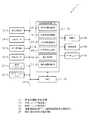
以下、図面を参照して本発明の実施の形態の一例を詳細に説明する。図1は、本実施形態に係る車両用運転支援装置の構成を示すブロック図である。なお、以下では、車両周辺を監視し、目的地まで自動運転により走行可能な車両用運転支援装置を一例として説明する。 Hereinafter, an example of an embodiment of the present invention will be described in detail with reference to the drawings. FIG. 1 is a block diagram showing the configuration of the vehicle driving assistance device according to the present embodiment. In the following, a vehicle driving assistance device that monitors the surroundings of the vehicle and can travel to a destination by automatic driving will be described as an example.
車両用運転支援装置10は、通信制御部12、外部センサ14、GPS(Global Positioning System)受信部16、内部センサ18、地図データベース20、及びナビゲーションシステム22を含んで構成されている。通信制御部12、外部センサ14、GPS受信部16、内部センサ18、地図データベース20、及びナビゲーションシステム22は、CAN(Controller Area Network)等の車載ネットワーク24に各々接続されている。車載ネットワーク24には、自動運転制御ECU(Electronic Control Unit)26、及びHMI(Human Machine Interface)28の各々が更に接続されている。なお、自動運転制御ECU26は運転制御部及び制御部の一例に対応し、HMI28は操作部及び表示部の一例に対応する。 The vehicle
通信制御部12は、車両と該車両の外部との間で車両の周辺情報等を授受する。例えば、道路側に設けられたインフラ(例えば、光ビーコン等)と通信を行い、交通情報等の周辺情報を受信する。また、通信制御部12は、クラウド等の外部のサーバなどと携帯電話通信網等のネットワークを介して通信する。通信制御部12は、取得した周辺情報等の情報を車載ネットワーク24に接続された機器へ送信可能とされている。 The communication control unit 12 transmits/receives vehicle peripheral information and the like between the vehicle and the outside of the vehicle. For example, it communicates with an infrastructure (for example, an optical beacon) provided on the road side and receives peripheral information such as traffic information. Further, the communication control unit 12 communicates with an external server such as a cloud via a network such as a mobile phone communication network. The communication control unit 12 is capable of transmitting information such as the acquired peripheral information to devices connected to the vehicle-mounted network 24.
外部センサ14は、自車の周辺状況を検出する。外部センサ14は、カメラ、レーダー(Radar)、及びライダー(LIDER:Laser Imaging Detection and Ranging)のうち少なくとも一つを含む。カメラは、例えば、車両のフロントガラス上部の室内側に設けられ、車両の外部状況を撮影することにより撮像情報を取得する。カメラは、取得した撮影情報を車載ネットワーク24に接続された機器へ送信可能とされている。カメラは、単眼カメラであってもよく、ステレオカメラであってもよい。ステレオカメラの場合、両眼視差を再現するように配置された二つの撮像部を有する。ステレオカメラの撮像情報には、奥行き方向の情報も含まる。レーダーは、電波(例えばミリ波)を車両の周囲に送信し、障害物で反射された電波を受信することで障害物を検出し、検出した障害物情報を車載ネットワーク24に接続された機器へ送信可能とされている。ライダーは、光を車両の周囲に送信し、障害物で反射された光を受信することで反射点までの距離を計測し、障害物を検出する。ライダーは、検出した障害物情報を車載ネットワーク24に接続された機器へ送信可能とされている。なお、カメラ、ライダー及びレーダーは、必ずしも重複して備える必要はない。 The external sensor 14 detects the surroundings of the vehicle. The external sensor 14 includes at least one of a camera, a radar, and a lidar (LIDER: Laser Imaging Detection and Ranging). The camera is provided, for example, on the interior side of the upper part of the windshield of the vehicle, and acquires imaging information by capturing an image of the outside of the vehicle. The camera is capable of transmitting the acquired shooting information to the device connected to the vehicle-mounted network 24. The camera may be a monocular camera or a stereo camera. In the case of a stereo camera, it has two imaging units arranged so as to reproduce binocular parallax. The imaging information of the stereo camera also includes information in the depth direction. The radar detects an obstacle by transmitting a radio wave (for example, a millimeter wave) around the vehicle and receiving the radio wave reflected by the obstacle, and transmits the detected obstacle information to a device connected to the vehicle-mounted network 24. It is possible to send. The rider transmits light to the surroundings of the vehicle, receives the light reflected by the obstacle, measures the distance to the reflection point, and detects the obstacle. The rider can transmit the detected obstacle information to the device connected to the vehicle-mounted network 24. The camera, the rider, and the radar do not necessarily have to be provided in duplicate.
GPS受信部16は、3個以上のGPS衛星から信号を受信することにより、車両の位置(例えば車両の緯度及び経度)を測位する。GPS受信部16は、測位した車両の位置情報を車載ネットワーク24に接続された機器へ送信可能とされている。なお、GPS受信部16に代えて、車両の緯度及び経度が特定できる他の手段を用いてもよい。また、車両の方位を測定する機能を持たせることは、センサの測定結果と後述する地図情報との照合のために好ましい。 The GPS reception unit 16 measures the position of the vehicle (for example, the latitude and longitude of the vehicle) by receiving signals from three or more GPS satellites. The GPS receiver 16 is capable of transmitting the position information of the positioned vehicle to the device connected to the in-vehicle network 24. It should be noted that instead of the GPS receiving unit 16, other means capable of specifying the latitude and longitude of the vehicle may be used. Further, it is preferable to have a function of measuring the azimuth of the vehicle in order to collate the measurement result of the sensor with the map information described later.
内部センサ18は、自車の走行時の各種物理量を検出することにより走行状態等の車両状況を検出する。内部センサ18は、例えば、車速センサ、加速度センサ、及びヨーレートセンサのうち少なくとも一つを含む。車速センサは、例えば、車両の車輪又は車輪と一体に回転するハブやロータ、ドライブシャフト等に設けられ、車輪の回転速度を検出することで車速を検出する。車速センサは、検出した車速情報(車輪速情報)を車載ネットワーク24に接続された機器へ送信可能とされている。加速度センサは、車両の加減速や、旋回、衝突等によって発生する加速度を検出する。加速度センサは、例えば、車両の前後方向の加速度を検出する前後加速度センサと、車両の左右方向(車幅方向)の横加速度を検出する横加速度センサと、車両の上下方向の加速度を検出する上下加速度センサと、を含む。加速度センサは、車両の加速度情報を車載ネットワーク24に接続された機器へ送信可能とされている。ヨーレートセンサは、車両の重心の鉛直軸周りのヨーレート(回転角速度)を検出する。ヨーレートセンサとしては、例えばジャイロセンサを用いることができる。ヨーレートセンサは、検出したヨーレート情報を車載ネットワーク24に接続された機器へ送信可能とされている。 The
地図データベース20は、地図情報を備えたデータベースである。地図データベース20は、例えば、車両に搭載されたHDD[Hard disk drive]内に記憶される。地図情報には、例えば、道路の位置情報、道路形状の情報(例えばカーブ、直線部の種別、カーブの曲率等)、交差点及び分岐点の位置情報が含まれる。さらに、建物や壁等の遮蔽構造物の位置情報、SLAM(Simultaneous Localization and Mapping)技術を使用するために、地図情報に外部センサ14の出力信号を含ませてもよい。なお、地図データベース20は、車両と通信可能な情報処理センター等の施設のコンピュータに記憶してもよい。 The map database 20 is a database including map information. The map database 20 is stored in, for example, an HDD [Hard disk drive] mounted on the vehicle. The map information includes, for example, road position information, road shape information (for example, a curve, a type of straight line portion, a curvature of a curve, etc.), and position information of intersections and branch points. Further, the output information of the external sensor 14 may be included in the map information in order to use the position information of the shielding structure such as a building or a wall and the SLAM (Simultaneous Localization and Mapping) technology. The map database 20 may be stored in a computer of a facility such as an information processing center that can communicate with the vehicle.
ナビゲーションシステム22は、車両の運転者によって設定された目的地まで、車両の運転者に対して案内を行う。ナビゲーションシステム22は、GPS受信部16によって測位された車両の位置情報と地図データベース20の地図情報とに基づいて、車両の走行するルートを算出する。ルートは、複数車線の区間において好適な車線を特定したものであってもよい。ナビゲーションシステム22は、例えば、車両の位置から目的地に至るまでの目標ルートを演算し、ディスプレイへの表示及びスピーカの音声出力により目標ルートを乗員に報知する。ナビゲーションシステム22は、車両の目標ルートの情報を車載ネットワーク24に接続された機器へ送信可能とされている。なお、ナビゲーションシステム22の機能は、車両と通信可能な情報処理センター等の施設のコンピュータに格納してもよい。 The navigation system 22 guides the driver of the vehicle to a destination set by the driver of the vehicle. The navigation system 22 calculates the route traveled by the vehicle based on the vehicle position information determined by the GPS receiver 16 and the map information in the map database 20. The route may specify a suitable lane in a section of a plurality of lanes. The navigation system 22 calculates, for example, a target route from the position of the vehicle to the destination, and notifies the occupant of the target route by displaying the target route on the display and outputting sound from a speaker. The navigation system 22 is capable of transmitting information on the target route of the vehicle to the devices connected to the in-vehicle network 24. The functions of the navigation system 22 may be stored in a computer in a facility such as an information processing center that can communicate with the vehicle.
自動運転制御ECU26は、CPU(Central Processing Unit)、ROM(Read Only Memory)、及びRAM(Random Access Memory)等を含むマイクロコンピュータで構成されている。また、自動運転制御ECU26には、アクチュエータ34、補助機器36、制動灯38、及びHMI28が接続されている。 The automatic
自動運転制御ECU26は、ROMに予め記憶されたプログラムをRAMに展開してCPUが実行することで、アクチュエータ34、補助機器36、制動灯38、及びHMI28等の動作を制御して自動運転を行う。なお、自動運転制御ECU26は、複数の電子制御ユニットから構成されていてもよい。 The automatic
アクチュエータ34は、車両の自動運転制御を行う場合の制御対象であり、自動運転制御ECU26がアクチュエータ34の動作を制御することにより車両の走行制御を行う。具体的には、アクチュエータ34は、スロットルアクチュエータ、ブレーキアクチュエータ、及び操舵アクチュエータを少なくとも含む。スロットルアクチュエータは、自動運転制御ECU26の指示に応じてエンジンに対する空気の供給量(スロットル開度)を制御し、車両の駆動力を制御する。なお、車両がハイブリッド車又は電気自動車である場合には、スロットルアクチュエータを含まず、動力源としてのモータに自動運転制御ECU26の指示が入力されて当該駆動力が制御される。ブレーキアクチュエータは、自動運転制御ECU26の指示に応じてブレーキシステムを制御し、車両の車輪へ付与する制動力を制御すると共に、制動灯38の点灯を制御する。ブレーキシステムとしては、例えば、液圧ブレーキシステムを用いることができる。操舵アクチュエータは、電動パワーステアリングシステムのうち操舵トルクを制御するアシストモータの駆動を、自動運転制御ECU26の指示に応じて制御する。これにより、操舵アクチュエータは、車両の操舵トルクを制御する。補助機器36は、通常、車両の運転者によって操作され得る機器である。補助機器36は、アクチュエータ34に含まれない機器を総称したものである。ここでの補助機器36は、例えば、方向指示灯や、前照灯、ワイパー等を含む。 The
詳細には、自動運転制御ECU26は、車両位置認識部40、外部状況認識部42、走行状態認識部44、走行計画生成部46、走行制御部48、及び補助機器制御部50を含んで構成されている。自動運転制御ECU26は、上記各部により車両の周辺情報と地図情報とに基づいて予め設定された目標ルートに沿った走行計画を生成し、生成した走行計画に従って車両が自立走行するよう運転を制御する。 Specifically, the automatic
車両位置認識部40は、GPS受信部16で受信した車両の位置情報、及び地図データベース20の地図情報に基づいて、地図上における車両の位置(以下、「車両位置」という)を認識する。なお、車両位置認識部40は、ナビゲーションシステム22で用いられる車両位置を該ナビゲーションシステム22から取得して認識してもよい。車両位置認識部40は、道路等の外部に設置されたセンサで車両位置が測定され得る場合、このセンサから通信によって車両位置を取得してもよい。 The vehicle
外部状況認識部42は、通信制御部12が取得した周辺情報や外部センサ14の検出結果(例えば、カメラの撮像情報や、レーダーの障害物情報、ライダーの障害物情報等)に基づいて、車両の外部状況を認識する。外部状況は、例えば、車両に対する走行車線の白線の位置や、車線中心の位置、道路幅、道路形状、車両の周辺の障害物の状況等を含む。なお、道路形状としては、例えば、走行車線の曲率、外部センサ14の見通し推定に有効な路面の勾配変化、うねり等がある。また、車両の周辺の障害物の状況としては、例えば、固定障害物と移動障害物を区別する情報、車両に対する障害物の位置、車両に対する障害物の移動方向、車両に対する障害物の相対速度等がある。また、外部センサ14の検出結果と地図情報とを照合することにより、GPS受信部16等で取得される車両の位置及び方向の精度を補うことは好適である。 The external situation recognizing unit 42, based on the peripheral information acquired by the communication control unit 12 and the detection result of the external sensor 14 (for example, image pickup information of the camera, obstacle information of the radar, obstacle information of the rider, etc.), the vehicle. Recognize the external situation of. The external condition includes, for example, the position of the white line of the traveling lane with respect to the vehicle, the position of the lane center, the road width, the road shape, the condition of obstacles around the vehicle, and the like. Note that the road shape includes, for example, the curvature of the traveling lane, the road surface gradient change effective for estimating the line of sight of the external sensor 14, the swell, and the like. In addition, as the situation of the obstacle around the vehicle, for example, information for distinguishing the fixed obstacle from the moving obstacle, the position of the obstacle with respect to the vehicle, the moving direction of the obstacle with respect to the vehicle, the relative speed of the obstacle with respect to the vehicle, etc. There is. In addition, it is preferable to supplement the accuracy of the position and direction of the vehicle acquired by the GPS receiving unit 16 or the like by collating the detection result of the external sensor 14 with the map information.
走行状態認識部44は、内部センサ18の検出結果(例えば、車速センサの車速情報、加速度センサの加速度情報、ヨーレートセンサのヨーレート情報等)に基づいて、車両の走行状態を認識する。車両の走行状態には、例えば、車速、加速度、ヨーレートが含まれる。 The traveling
走行計画生成部46は、例えば、ナビゲーションシステム22で演算された目標ルート、車両位置認識部40で認識された車両位置、及び、外部状況認識部42で認識された車両の外部状況(車両位置、方位を含む)に基づいて、車両の進路を生成する。生成する進路としては、目標ルートにおいて車両が進む軌跡を生成する。走行計画生成部46は、目標ルート上において車両が安全、法令順守、走行効率等の基準に照らして好適に走行するように進路を生成する。このとき、走行計画生成部46は、車両の周辺の障害物の状況に基づき、障害物との接触を回避するように車両の進路を生成することはいうまでもない。なお、上記目標ルートには、例えば、特許5382218号公報(WO2011/158347号公報)や特開2011−162132号公報等における道なり走行のように、目的地の設定が運転者から明示的に行われていない際に、外部状況や地図情報に基づき自動的に生成される走行ルートも含まれる。走行計画生成部46は、生成した進路に応じた走行計画を生成する。すなわち、走行計画生成部46は、少なくとも車両の周辺情報である外部状況と地図データベース20の地図情報とに基づいて、予め設定された目標ルートに沿った走行計画を生成する。走行計画生成部46は、好ましくは、生成する走行計画を、車両の進路を車両に固定された座標系での目標位置pと各目標点での速度vとの二つの要素からなる組、すなわち配位座標(p、v)を複数持つものとして出力する。ここで、それぞれの目標位置pは、少なくとも車両に固定された座標系でのx座標、y座標の位置もしくはそれと等価な情報を有する。なお、走行計画は、車両の挙動を記すものであれば特に限定されるものではない。走行計画は、例えば、速度vの代わりに目標時刻tを用いてもよいし、目標時刻tとその時点での車両の方位とを付加したものでもよい。また、通常、走行計画は、概ね現在時刻から数秒先の将来のデータで充分であるが、交差点の右折、車両の追い越し等の状況によっては数十秒のデータが必要となるので、走行計画の配位座標の数は可変、且つ配位座標間の距離も可変とすることが好ましい。さらに、配位座標をつなぐ曲線をスプライン関数等で近似し、当該曲線のパラメータを走行計画としてもよい。走行計画の生成としては、車両の挙動を記すことができるものであれば、任意の公知方法を用いることができる。また、走行計画は、目標ルートに沿った進路を車両が走行する際における、車両の車速、加減速度及び操舵トルク等の推移を示すデータとしてもよい。走行計画は、車両の速度パターン、加減速度パターン及び操舵パターンを含んでいてもよい。ここでの走行計画生成部46は、旅行時間(車両が目的地に到着するまでに要される所要時間)が最も小さくなるように、走行計画を生成してもよい。ちなみに、速度パターンとは、例えば、進路上に所定間隔(例えば1m)で設定された目標制御位置に対して、目標制御位置ごとに時間に関連付けられて設定された目標車速からなるデータである。加減速度パターンとは、例えば、進路上に所定間隔(例えば1m)で設定された目標制御位置に対して、目標制御位置ごとに時間に関連付けられて設定された目標加減速度からなるデータである。操舵パターンとは、例えば、進路上に所定間隔(例えば1m)で設定された目標制御位置に対して、目標制御位置ごとに時間に関連付けられて設定された目標操舵トルクからなるデータである。 The travel
走行制御部48は、走行計画生成部46で生成した走行計画に基づいて車両の走行を自動で制御する。走行制御部48は、走行計画に応じた制御信号をアクチュエータ34に出力する。これにより、走行制御部48は、走行計画に沿って車両が自立走行するように、車両の運転を制御する。また、自立走行するために、走行制御部48は、車両の走行を制御する際に、車両位置認識部40、外部状況認識部42、及び走行状態認識部44の各認識結果を監視しながら走行計画に従って車両の走行を制御するようになっている。 The
補助機器制御部50は、走行計画生成部46で生成した走行計画にHMI28から出力される信号を統合して補助機器36を制御する。 The auxiliary
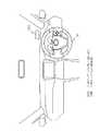
HMI28は、乗員への車両の状態等の各種情報の報知と、乗員からの情報の入力とを行う。HMI28は、例えば、方向指示灯、前照灯、ワイパー等を操作するためのスイッチ、自動運転に関する切替スイッチ、各種情報を表示するディスプレイ、操作入力を行うための操作部、及び各種情報を報知するための発光デバイスやスピーカ等を含む。なお、自動運転に関する切替スイッチは、自動運転と手動運転との切り替えの指示や、自動運転から手動運転への切り替えの終了の指示等が可能とされている。具体的には、HMI28は、図2に示すように、ステアリング56に設けられた十字キースイッチ28B、及びフロントウインドシールドガラスの予め定めた領域が表示領域とされたヘッドアップディスプレイ28Aを含む。本実施形態では、操作部の一例としての十字キースイッチ28Bにより、自動運転中の追越しの指示及び設定車速変更を少なくとも含む操作が可能とされている。また、十字キースイッチ28Bの操作に応じて指示された内容が表示部の一例としてのヘッドアップディスプレイ28Aに表示される。 The
ここで、十字キースイッチ28Bを操作することによって指示可能な内容と、ヘッドアップディスプレイ28Aへの表示例について説明する。図3は、ヘッドアップディスプレイ28Aの表示例を示す図である。 Here, contents that can be instructed by operating the cross
表示例1は、前方に車両がいない場合に十字キースイッチ28Bの上下スイッチが操作された場合の表示例である。前方に車両がいない場合に、十字キースイッチ28Bが操作されると、設定車速変更画面がヘッドアップディスプレイ28Aに表示される。十字キースイッチの「上」を操作するたびに設定車速が変更されてヘッドアップディスプレイ28Aに表示される。 Display example 1 is a display example when the up/down switch of the cross
表示例2では、前方に車両がいる場合に十字キースイッチ28Bの上下スイッチが操作された場合の表示例である。前方に車両がいる場合に、十字キースイッチ28Bが操作されると、追越し指示画面が確定前の点滅状態でヘッドアップディスプレイ28Aに表示される。また、別候補が小さく右側に表示される。表示例2では、別候補として設定車速変更画面が小さく表示されている例を示す。十字キースイッチ28Bの「上」が操作されると、追越し指示を確定して点滅を停止し、追越し指示画面がヘッドアップディスプレイ28Aに表示される。 The display example 2 is a display example when the up and down switches of the cross
表示例3では、表示例2において、別候補を選択した場合の表示例である。表示例2の状態で、十字キースイッチ28Bの「右」が操作されて場合には、右側に小さく表示されていた設定車速変更画面が大きく表示され、追越し指示画面が左側に別候補として小さく表示される。 Display example 3 is a display example when another candidate is selected in display example 2. In the state of the display example 2, when the “right” of the cross
なお、前方に車両がいない場合に設定車速変更画面を表示する場合には、表示例1の他に、表示例3のように、別候補を小さく表示してもよい。 When the set vehicle speed change screen is displayed when there is no vehicle ahead, another candidate may be displayed smaller, as in display example 3, in addition to display example 1.
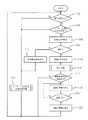
続いて、上述のように構成された本実施形態に係る車両用運転支援装置10において、自動運転中に十字キースイッチ28Bが操作された場合に自動運転制御ECU26で行われる操作及び表示に関する処理の一例について説明する。図4は、本実施形態に係る車両用運転支援装置の自動運転制御ECU26で行われる処理の流れの一例を示すフローチャートである。なお、図4の処理は、十字キースイッチ28Bが操作された場合に開始する。 Subsequently, in the vehicle driving
ステップ100では、自動運転制御ECU26が、前方車両があるか否かを判定する。該判定は、例えば、外部センサ14によって前方車両が検出されたか否かを判定し、判定が否定された場合にはステップ102へ移行し、肯定された場合にはステップ104へ移行する。 In
ステップ102では、自動運転制御ECU26が、上下キーによる設定車速変更処理を行ってステップ100に戻って上述の処理が繰り返される。設定車速変更処理は、図3に示す表示例1のように、設定車速変更画面をヘッドアップディスプレイ28Aに表示する。そして、十字キースイッチ28Bの上下キーの操作に従って設定車速を変更して、ヘッドアップディスプレイ28Aに表示すると共に、確定する操作が行われた場合に設定車速を変更する。 In
ステップ104では、自動運転制御ECU26が、十字キースイッチ28Bの「上」又は「下」が操作されたか否か判定する。十字キースイッチ28Bの「下」が操作された場合には、ステップ102へ移行し、「上」が操作された場合にはステップ106へ移行する。 In
ステップ106では、自動運転制御ECU26が、追越し指示画面をヘッドアップディスプレイ28Aに点滅表示するように制御してステップ108へ移行する。すなわち、自動運転中に十字キースイッチ28Bが操作された際に前方に車両がいる場合には、図3に示す表示例2のように、追越し指示画面を確定前の点滅状態で表示する。これにより、追越し指示が行われたことを点滅表示により確認することができ、誤操作による運転者の意図と異なる追越しを防止できる。また、図3に示すように、設定車速の変更画面を小さく表示することにより、設定車速変更指示を選択できることが分かり易くなる。 In
ステップ108では、自動運転制御ECU26が、追越し指示を確定するか否か判定する。該判定は、例えば、確定操作として十字キースイッチ28Bの「上」が操作されたか否かを判定し、十字キースイッチ28Bの「右」が操作された場合に判定が否定されてステップ110へ移行し、肯定された場合にはステップ112へ移行する。 In
ステップ110では、自動運転制御ECU26が、ヘッドアップディスプレイ28Aに設定車速変更画面を表示するように制御して上述のステップ102へ移行して設定車速変更処理を行う。 In
一方、ステップ112では、自動運転制御ECU26が、ヘッドアップディスプレイ28Aに追越し指示画面を表示するように制御してステップ114へ移行する。すなわち、図3に示す表示例2のように、追越し指示画面を表示する。 On the other hand, in
ステップ114では、自動運転制御ECU26が、周辺監視処理を行ってステップ116へ移行する。すなわち、外部センサ14によって追越しのための車線変更を行うにあたり、車線方向の車両等の監視を行う。なお、周辺監視処理は、外部センサ14による周辺状況の監視の他に、路車間通信や車車間通信等を行うことにより、周辺状況を監視してもよい。或いは、外部センサ14の検出結果、路車間通信の通信結果、及び車車間通信の通信結果の少なくとも1つに基づいて周辺状況を監視してもよい。なお、路車間通信や車車間通信については種々の周知技術を適用することができるため詳細な説明は省略する。 At
ステップ116では、自動運転制御ECU26が、車線変更方向に車両があるか否かを判定する。該判定が肯定された場合にはステップ118へ移行し、否定された場合にはステップ100に戻って上述の処理を繰り返す。なお、図4の処理は、操作及び表示に関する部分の処理を抜き出しているため省略しているが、ステップ116が否定された場合には車線変更を行って追越しを行うように制御が行われる。 In
ステップ118では、自動運転制御ECU26が、ヘッドアップディスプレイ28Aに追越し準備中を表示するように制御してステップ120へ移行する。 In
ステップ120では、自動運転制御ECU26が、追越し可能になったか否かを外部センサ14の検出結果に基づいて判定する。該判定が肯定された場合には、ステップ122へ移行し、否定された場合にはステップ118に戻って、追越し準備中の表示を継続する。 In
ステップ122では、自動運転制御ECU26が、ヘッドアップディスプレイ28Aに表示された追越し準備中を消灯してステップ100に戻って上述の処理を繰り返す。すなわち、車線変更方向に車両等がある場合などの追越しが不可能な状況では、追越し指示が行われても追越しを待機する。これにより、先行車が車線変更するなどの先行車の状況に応じて運転できるため、運転者が不快と感じる機会を低減できる。 In
このように、本実施形態では、設定車速変更の操作と同じ十字キースイッチ28Bの操作を行うことにより、自動運転中の追越し指示の操作を行うことができる。すなわち、既存の設定車速変更するためのスイッチを用いて自動運転中の追越し指示の操作を行うことができるので、追越し指示用のスイッチの設置スペースが不要となると共に、スイッチ数が増加することがない。 As described above, in the present embodiment, the operation of the overtaking instruction during the automatic driving can be performed by performing the same operation of the cross
また、設定速度変更の速度アップ操作と同じ操作である、十字キースイッチ28Bの「上」操作を行うことで、追越し指示ができるので、他のスイッチ操作よりも直感的に操作することが可能となる。 In addition, since an overtaking instruction can be issued by performing an "up" operation of the cross
なお、上記の実施形態では、十字キースイッチ28Bを操作部の一例として説明したがこれに限るものではなく、他のスイッチやタッチセンサを適用してもよい。 In the above embodiment, the cross
また、上記の実施形態では、ヘッドアップディスプレイ28Aを表示部の一例として説明したが、これに限るものではなく、例えば、インストルメントパネル等に設けられたディスプレイ等の他のディスプレイを適用してもよい。 Further, although the head-up
また、上記の実施形態では、自動運転制御ECU26が、自動運転として、周辺状況を監視しながら自立走行可能な例を説明したが、自動運転はこれに限るものではない。例えば、高速道路走行中に設定車速で走行し、かつ先行車を検出した場合に追従して走行、または追越しを行う運転支援を適用してもよい。すなわち、運転操作の少なくとも一部を制御して前方車両を追い越す追越し運転が可能な自動運転であれば、上記の自動運転に限るものではない。 Further, in the above embodiment, an example in which the automatic
また、上記の実施形態では、前方に車両がいる状態で十字キースイッチ28Bの「上」が操作された場合に、追越し指示の操作とする例を説明したが、これに限るものではない。例えば、前方に車両がいる状態で十字キースイッチ28Bの「下」が操作された場合に、追越し指示の操作としてもよい。或いは、十字キースイッチ28Bの「右」や「左」の操作を「上」の操作の代わりとしてもよい。 Further, in the above-described embodiment, an example in which the overtaking instruction is performed when the “up” of the cross
また、上記の実施形態における自動運転制御ECU26で行われる図4に示す処理は、プログラムを実行することにより行われるソフトウエア処理として説明したが、ハードウエアで行う処理としてもよい。或いは、ソフトウエア及びハードウエアの双方を組み合わせた処理としてもよい。また、ROMに記憶されるプログラムは、各種記憶媒体に記憶して流通させるようにしてもよい。 Further, although the processing shown in FIG. 4 performed by the automatic
さらに、本発明は、上記に限定されるものでなく、上記以外にも、その主旨を逸脱しない範囲内において種々変形して実施可能であることは勿論である。 Furthermore, the present invention is not limited to the above, and it goes without saying that other than the above, various modifications can be carried out without departing from the scope of the invention.
10 車両用運転支援装置
14 外部センサ(検出部)
18 内部センサ(検出部)
26 自動運転制御ECU(運転制御部及び制御部)
28 HMI(操作部及び表示部)
28A ヘッドアップディスプレイ(表示部)
28B 十字キースイッチ(操作部)10 Vehicle Driving Support Device 14 External Sensor (Detection Unit)
18 Internal sensor (detection unit)
26 Automatic operation control ECU (operation control unit and control unit)
28 HMI (operation unit and display unit)
28A Head-up display (display section)
28B Cross key switch (operation section)
Claims (4)
Translated fromJapanese前記検出部の検出結果に基づいて、自車の運転操作の少なくとも一部を制御して前方車両を追い越す追越し運転が可能な自動運転を制御する運転制御部と、
前記自動運転中の設定車速を変更する操作を行うための操作部と、
前記追越し運転を行うか、設定車速を変更させるかを選択させる画面を表示する表示部と、
前記自動運転中に前記検出部によって前方車両が検出されている状態で、前記操作部によって設定車速を上げる操作が行われた場合に、前記画面を表示して前記操作部によって前記設定車速を上げる操作が再び行われることにより前記追越し運転が選択されて、前記追越し運転を行うように、前記表示部及び前記運転制御部を制御する制御部と、
を備えた車両用運転支援装置。A detection unit that detects the surrounding condition of the own vehicle and the running state of the own vehicle,
Based on the detection result of the detection unit, a driving control unit that controls at least a part of the driving operation of the own vehicle to control the automatic driving capable of overtaking driving to pass the preceding vehicle,
An operation unit for performing an operation of changing the set vehicle speed during the automatic driving,
Whether to perform theovertaking his operation, and a display unit for displaying a screen for selecting whether to change the vehicle speed setting,
When the operation unitincreases the set vehicle speed while the vehicle ahead is being detected by the detection unit during the automatic driving, the screen is displayed and theoperation unit increases the set vehicle speed. operationis selected theovertaking said operationby being performed again, the overtaking to perform the operation, and a control section for controlling the display unit and the operation control unit,
Vehicle driving support device.
Priority Applications (4)
| Application Number | Priority Date | Filing Date | Title |
|---|---|---|---|
| JP2016175721AJP6729220B2 (en) | 2016-09-08 | 2016-09-08 | Vehicle driving support device |
| US15/668,222US10549780B2 (en) | 2016-09-08 | 2017-08-03 | Driving assistance device for a vehicle |
| DE102017117698.5ADE102017117698B4 (en) | 2016-09-08 | 2017-08-04 | Driver assistance device for a vehicle |
| CN201710795084.6ACN107807634B (en) | 2016-09-08 | 2017-09-06 | Driving assistance device for vehicle |
Applications Claiming Priority (1)
| Application Number | Priority Date | Filing Date | Title |
|---|---|---|---|
| JP2016175721AJP6729220B2 (en) | 2016-09-08 | 2016-09-08 | Vehicle driving support device |
Publications (2)
| Publication Number | Publication Date |
|---|---|
| JP2018039412A JP2018039412A (en) | 2018-03-15 |
| JP6729220B2true JP6729220B2 (en) | 2020-07-22 |
Family
ID=61198171
Family Applications (1)
| Application Number | Title | Priority Date | Filing Date |
|---|---|---|---|
| JP2016175721AActiveJP6729220B2 (en) | 2016-09-08 | 2016-09-08 | Vehicle driving support device |
Country Status (4)
| Country | Link |
|---|---|
| US (1) | US10549780B2 (en) |
| JP (1) | JP6729220B2 (en) |
| CN (1) | CN107807634B (en) |
| DE (1) | DE102017117698B4 (en) |
Families Citing this family (23)
| Publication number | Priority date | Publication date | Assignee | Title |
|---|---|---|---|---|
| JP6579144B2 (en)* | 2017-03-28 | 2019-09-25 | 株式会社Soken | Obstacle detection device |
| DE102017212992A1 (en)* | 2017-07-27 | 2019-01-31 | Continental Automotive Gmbh | System for selecting driving maneuvers of a vehicle for automated driving |
| JP6596772B2 (en)* | 2017-09-01 | 2019-10-30 | 本田技研工業株式会社 | Vehicle control device, vehicle control method, and program |
| DE102017218661A1 (en)* | 2017-10-19 | 2019-04-25 | Audi Ag | Method for operating at least one electric machine |
| US11097747B2 (en)* | 2018-03-27 | 2021-08-24 | Nissan Motor Co., Ltd. | Method and device for controlling autonomously driven vehicle |
| US10836394B2 (en)* | 2018-04-11 | 2020-11-17 | Hyundai Motor Company | Apparatus and method for lane change control |
| WO2019200563A1 (en)* | 2018-04-18 | 2019-10-24 | Baidu. Com Times Technology (Beijing) Co., Ltd. | Map-less and localization-less lane following method for autonomous driving of autonomous driving vehicles on highway |
| DE102018207572A1 (en)* | 2018-05-16 | 2019-11-21 | Ford Global Technologies, Llc | Adaptive speed controller for motor vehicles and adaptive speed control method |
| JP6676697B2 (en)* | 2018-05-24 | 2020-04-08 | 本田技研工業株式会社 | Vehicle control device, vehicle control method, and program |
| JP6710722B2 (en)* | 2018-06-15 | 2020-06-17 | 本田技研工業株式会社 | Vehicle control device, vehicle control method, and program |
| JP2020052646A (en)* | 2018-09-26 | 2020-04-02 | トヨタ自動車株式会社 | Vehicle control device |
| US10752242B2 (en)* | 2018-11-19 | 2020-08-25 | GM Global Technology Operations LLC | System and method for control of an autonomous vehicle |
| DE102018129572A1 (en)* | 2018-11-23 | 2020-05-28 | Bayerische Motoren Werke Aktiengesellschaft | Driver assistance system for an automated vehicle and method for driving an automated vehicle |
| JP7176968B2 (en)* | 2019-02-07 | 2022-11-22 | 本田技研工業株式会社 | VEHICLE CONTROL DEVICE, VEHICLE AND VEHICLE CONTROL METHOD |
| JP7212537B2 (en)* | 2019-02-07 | 2023-01-25 | 本田技研工業株式会社 | VEHICLE CONTROL DEVICE, VEHICLE AND VEHICLE CONTROL METHOD |
| DE102019203610A1 (en)* | 2019-03-18 | 2020-09-24 | Honda Motor Co., Ltd. | Vehicle ride assistance device |
| JP7243589B2 (en)* | 2019-11-15 | 2023-03-22 | トヨタ自動車株式会社 | vehicle controller |
| US11107357B2 (en)* | 2019-11-21 | 2021-08-31 | Aptiv Technologies Limited | Process and system for assisting vehicle operations with safe passing |
| JP6993441B2 (en) | 2020-01-31 | 2022-01-13 | 本田技研工業株式会社 | Vehicle control device, vehicle, operation method and program of vehicle control device |
| JP7363621B2 (en)* | 2020-03-17 | 2023-10-18 | トヨタ自動車株式会社 | Information processing device, information processing method, and program |
| JP7534181B2 (en)* | 2020-10-13 | 2024-08-14 | 株式会社Subaru | Vehicle display device |
| JP7491203B2 (en)* | 2020-12-09 | 2024-05-28 | トヨタ自動車株式会社 | Control device, system, vehicle, program, and control device operation method |
| JP7582064B2 (en)* | 2021-05-19 | 2024-11-13 | トヨタ自動車株式会社 | DISPLAY CONTROL DEVICE, DISPLAY CONTROL METHOD, AND DISPLAY CONTROL PROGRAM |
Family Cites Families (21)
| Publication number | Priority date | Publication date | Assignee | Title |
|---|---|---|---|---|
| JPS5382218A (en) | 1976-12-28 | 1978-07-20 | Nec Corp | Television signal coding unit |
| JP3889131B2 (en)* | 1997-09-30 | 2007-03-07 | 本田技研工業株式会社 | Vehicle travel control device |
| JP3573081B2 (en)* | 2000-10-10 | 2004-10-06 | トヨタ自動車株式会社 | Travel control device for vehicles |
| JP2003063273A (en) | 2001-08-30 | 2003-03-05 | Hitachi Ltd | Vehicle running controller |
| CN2675457Y (en)* | 2004-02-07 | 2005-02-02 | 黄仰圣 | Semi automatic driving device for hand-operated gear shift step-speed-changing automobile |
| JP2007034612A (en)* | 2005-07-26 | 2007-02-08 | Sony Corp | Card tray |
| JP2008024122A (en)* | 2006-07-20 | 2008-02-07 | Mazda Motor Corp | Traveling controller of vehicle |
| DE102009008142A1 (en) | 2009-02-09 | 2010-08-19 | Technische Universität Darmstadt | Method for controlling a driver assistance system and driver assistance system |
| JP2011162132A (en) | 2010-02-12 | 2011-08-25 | Toyota Motor Corp | Automatic driving device |
| DE102010022620A1 (en) | 2010-06-04 | 2011-12-08 | Volkswagen Ag | Motor vehicle has maneuver assistance system for automatic execution of driving maneuvers of motor vehicle, where motor vehicle has cross-like out-arranged operating arrangements for operating maneuver assistance system |
| WO2011158347A1 (en) | 2010-06-16 | 2011-12-22 | トヨタ自動車株式会社 | Driving assistance device |
| JP5427203B2 (en)* | 2011-03-30 | 2014-02-26 | 富士重工業株式会社 | Vehicle driving support device |
| JP6056682B2 (en)* | 2013-06-27 | 2017-01-11 | 株式会社デンソー | Vehicle information providing device |
| US9988047B2 (en)* | 2013-12-12 | 2018-06-05 | Magna Electronics Inc. | Vehicle control system with traffic driving control |
| EP2902864B1 (en)* | 2014-01-30 | 2017-05-31 | Volvo Car Corporation | Control arrangement for autonomously driven vehicle |
| WO2015176723A1 (en) | 2014-05-22 | 2015-11-26 | Conti Temic Microelectronic Gmbh | Method and device for increasing safety during an overtaking process of a vehicle |
| JP6322063B2 (en) | 2014-06-17 | 2018-05-09 | 株式会社Subaru | Vehicle driving support device |
| JP6322062B2 (en)* | 2014-06-17 | 2018-05-09 | 株式会社Subaru | Vehicle driving support device |
| JP5970513B2 (en) | 2014-09-29 | 2016-08-17 | 富士重工業株式会社 | Driving support control device |
| US10589751B2 (en)* | 2014-12-31 | 2020-03-17 | Robert Bosch Gmbh | Autonomous maneuver notification for autonomous vehicles |
| JP5910904B1 (en) | 2015-07-31 | 2016-04-27 | パナソニックIpマネジメント株式会社 | Driving support device, driving support system, driving support method, driving support program, and autonomous driving vehicle |
- 2016
- 2016-09-08JPJP2016175721Apatent/JP6729220B2/enactiveActive
- 2017
- 2017-08-03USUS15/668,222patent/US10549780B2/enactiveActive
- 2017-08-04DEDE102017117698.5Apatent/DE102017117698B4/enactiveActive
- 2017-09-06CNCN201710795084.6Apatent/CN107807634B/enactiveActive
Also Published As
| Publication number | Publication date |
|---|---|
| JP2018039412A (en) | 2018-03-15 |
| CN107807634B (en) | 2021-10-26 |
| US20180065664A1 (en) | 2018-03-08 |
| DE102017117698A1 (en) | 2018-03-08 |
| CN107807634A (en) | 2018-03-16 |
| US10549780B2 (en) | 2020-02-04 |
| DE102017117698B4 (en) | 2020-06-04 |
Similar Documents
| Publication | Publication Date | Title |
|---|---|---|
| JP6729220B2 (en) | Vehicle driving support device | |
| JP7140037B2 (en) | Vehicle remote indication system | |
| US10293748B2 (en) | Information presentation system | |
| JP6323385B2 (en) | Vehicle travel control device | |
| JP7172257B2 (en) | Autonomous driving system | |
| JP6365390B2 (en) | Lane change support device | |
| JP7238670B2 (en) | image display device | |
| JP6137212B2 (en) | Driving assistance device | |
| JP6361567B2 (en) | Automated driving vehicle system | |
| US20160304126A1 (en) | Vehicle control device | |
| US9896098B2 (en) | Vehicle travel control device | |
| EP3121076A2 (en) | Vehicle control device | |
| JP2017087816A (en) | Automatic drive system | |
| JP2018100009A (en) | Vehicle control device | |
| JP2017001597A (en) | Automatic driving device | |
| JP2016212630A (en) | Travel control device | |
| JP7152339B2 (en) | Travel control device, travel control method, and program | |
| JP2017074823A (en) | Lane change support device | |
| JP2017076232A (en) | Vehicle-purposed notification device | |
| JP2018118609A (en) | Automated driving system | |
| JP2019106050A (en) | Driving support device | |
| JP6414005B2 (en) | Vehicle control device | |
| JP2017189989A (en) | Lane keep apparatus | |
| JP2017073059A (en) | Lane change support device | |
| JP2017140928A (en) | Automatic driving device |
Legal Events
| Date | Code | Title | Description |
|---|---|---|---|
| A621 | Written request for application examination | Free format text:JAPANESE INTERMEDIATE CODE: A621 Effective date:20180619 | |
| A977 | Report on retrieval | Free format text:JAPANESE INTERMEDIATE CODE: A971007 Effective date:20190328 | |
| A131 | Notification of reasons for refusal | Free format text:JAPANESE INTERMEDIATE CODE: A131 Effective date:20190416 | |
| A521 | Request for written amendment filed | Free format text:JAPANESE INTERMEDIATE CODE: A523 Effective date:20190529 | |
| A131 | Notification of reasons for refusal | Free format text:JAPANESE INTERMEDIATE CODE: A131 Effective date:20191029 | |
| A521 | Request for written amendment filed | Free format text:JAPANESE INTERMEDIATE CODE: A523 Effective date:20191224 | |
| TRDD | Decision of grant or rejection written | ||
| A01 | Written decision to grant a patent or to grant a registration (utility model) | Free format text:JAPANESE INTERMEDIATE CODE: A01 Effective date:20200602 | |
| A61 | First payment of annual fees (during grant procedure) | Free format text:JAPANESE INTERMEDIATE CODE: A61 Effective date:20200615 | |
| R151 | Written notification of patent or utility model registration | Ref document number:6729220 Country of ref document:JP Free format text:JAPANESE INTERMEDIATE CODE: R151 |