JP6728062B2 - Debriding dressings for use with negative pressure and fluid drip - Google Patents
Debriding dressings for use with negative pressure and fluid dripDownload PDFInfo
- Publication number
- JP6728062B2 JP6728062B2JP2016566815AJP2016566815AJP6728062B2JP 6728062 B2JP6728062 B2JP 6728062B2JP 2016566815 AJP2016566815 AJP 2016566815AJP 2016566815 AJP2016566815 AJP 2016566815AJP 6728062 B2JP6728062 B2JP 6728062B2
- Authority
- JP
- Japan
- Prior art keywords
- tissue
- debridement
- holes
- hole
- negative pressure
- Prior art date
- Legal status (The legal status is an assumption and is not a legal conclusion. Google has not performed a legal analysis and makes no representation as to the accuracy of the status listed.)
- Active
Links
Images


Classifications
- A—HUMAN NECESSITIES
- A61—MEDICAL OR VETERINARY SCIENCE; HYGIENE
- A61B—DIAGNOSIS; SURGERY; IDENTIFICATION
- A61B17/00—Surgical instruments, devices or methods
- A61B17/32—Surgical cutting instruments
- A—HUMAN NECESSITIES
- A61—MEDICAL OR VETERINARY SCIENCE; HYGIENE
- A61B—DIAGNOSIS; SURGERY; IDENTIFICATION
- A61B17/00—Surgical instruments, devices or methods
- A61B17/32—Surgical cutting instruments
- A61B17/3205—Excision instruments
- A—HUMAN NECESSITIES
- A61—MEDICAL OR VETERINARY SCIENCE; HYGIENE
- A61F—FILTERS IMPLANTABLE INTO BLOOD VESSELS; PROSTHESES; DEVICES PROVIDING PATENCY TO, OR PREVENTING COLLAPSING OF, TUBULAR STRUCTURES OF THE BODY, e.g. STENTS; ORTHOPAEDIC, NURSING OR CONTRACEPTIVE DEVICES; FOMENTATION; TREATMENT OR PROTECTION OF EYES OR EARS; BANDAGES, DRESSINGS OR ABSORBENT PADS; FIRST-AID KITS
- A61F13/00—Bandages or dressings; Absorbent pads
- A61F13/01—Non-adhesive bandages or dressings
- A61F13/01008—Non-adhesive bandages or dressings characterised by the material
- A61F13/01017—Non-adhesive bandages or dressings characterised by the material synthetic, e.g. polymer based
- A—HUMAN NECESSITIES
- A61—MEDICAL OR VETERINARY SCIENCE; HYGIENE
- A61F—FILTERS IMPLANTABLE INTO BLOOD VESSELS; PROSTHESES; DEVICES PROVIDING PATENCY TO, OR PREVENTING COLLAPSING OF, TUBULAR STRUCTURES OF THE BODY, e.g. STENTS; ORTHOPAEDIC, NURSING OR CONTRACEPTIVE DEVICES; FOMENTATION; TREATMENT OR PROTECTION OF EYES OR EARS; BANDAGES, DRESSINGS OR ABSORBENT PADS; FIRST-AID KITS
- A61F13/00—Bandages or dressings; Absorbent pads
- A61F13/05—Bandages or dressings; Absorbent pads specially adapted for use with sub-pressure or over-pressure therapy, wound drainage or wound irrigation, e.g. for use with negative-pressure wound therapy [NPWT]
- A—HUMAN NECESSITIES
- A61—MEDICAL OR VETERINARY SCIENCE; HYGIENE
- A61L—METHODS OR APPARATUS FOR STERILISING MATERIALS OR OBJECTS IN GENERAL; DISINFECTION, STERILISATION OR DEODORISATION OF AIR; CHEMICAL ASPECTS OF BANDAGES, DRESSINGS, ABSORBENT PADS OR SURGICAL ARTICLES; MATERIALS FOR BANDAGES, DRESSINGS, ABSORBENT PADS OR SURGICAL ARTICLES
- A61L31/00—Materials for other surgical articles, e.g. stents, stent-grafts, shunts, surgical drapes, guide wires, materials for adhesion prevention, occluding devices, surgical gloves, tissue fixation devices
- A61L31/04—Macromolecular materials
- A61L31/06—Macromolecular materials obtained otherwise than by reactions only involving carbon-to-carbon unsaturated bonds
- A—HUMAN NECESSITIES
- A61—MEDICAL OR VETERINARY SCIENCE; HYGIENE
- A61L—METHODS OR APPARATUS FOR STERILISING MATERIALS OR OBJECTS IN GENERAL; DISINFECTION, STERILISATION OR DEODORISATION OF AIR; CHEMICAL ASPECTS OF BANDAGES, DRESSINGS, ABSORBENT PADS OR SURGICAL ARTICLES; MATERIALS FOR BANDAGES, DRESSINGS, ABSORBENT PADS OR SURGICAL ARTICLES
- A61L31/00—Materials for other surgical articles, e.g. stents, stent-grafts, shunts, surgical drapes, guide wires, materials for adhesion prevention, occluding devices, surgical gloves, tissue fixation devices
- A61L31/14—Materials characterised by their function or physical properties, e.g. injectable or lubricating compositions, shape-memory materials, surface modified materials
- A61L31/146—Porous materials, e.g. foams or sponges
- A—HUMAN NECESSITIES
- A61—MEDICAL OR VETERINARY SCIENCE; HYGIENE
- A61M—DEVICES FOR INTRODUCING MEDIA INTO, OR ONTO, THE BODY; DEVICES FOR TRANSDUCING BODY MEDIA OR FOR TAKING MEDIA FROM THE BODY; DEVICES FOR PRODUCING OR ENDING SLEEP OR STUPOR
- A61M1/00—Suction or pumping devices for medical purposes; Devices for carrying-off, for treatment of, or for carrying-over, body-liquids; Drainage systems
- A61M1/90—Negative pressure wound therapy devices, i.e. devices for applying suction to a wound to promote healing, e.g. including a vacuum dressing
- A61M1/91—Suction aspects of the dressing
- A61M1/915—Constructional details of the pressure distribution manifold
- A—HUMAN NECESSITIES
- A61—MEDICAL OR VETERINARY SCIENCE; HYGIENE
- A61B—DIAGNOSIS; SURGERY; IDENTIFICATION
- A61B17/00—Surgical instruments, devices or methods
- A61B2017/00743—Type of operation; Specification of treatment sites
- A61B2017/00747—Dermatology
- A61B2017/00761—Removing layer of skin tissue, e.g. wrinkles, scars or cancerous tissue
- A—HUMAN NECESSITIES
- A61—MEDICAL OR VETERINARY SCIENCE; HYGIENE
- A61B—DIAGNOSIS; SURGERY; IDENTIFICATION
- A61B17/00—Surgical instruments, devices or methods
- A61B17/32—Surgical cutting instruments
- A61B2017/320004—Surgical cutting instruments abrasive
- A—HUMAN NECESSITIES
- A61—MEDICAL OR VETERINARY SCIENCE; HYGIENE
- A61B—DIAGNOSIS; SURGERY; IDENTIFICATION
- A61B17/00—Surgical instruments, devices or methods
- A61B17/32—Surgical cutting instruments
- A61B2017/320004—Surgical cutting instruments abrasive
- A61B2017/320008—Scrapers
- A—HUMAN NECESSITIES
- A61—MEDICAL OR VETERINARY SCIENCE; HYGIENE
- A61B—DIAGNOSIS; SURGERY; IDENTIFICATION
- A61B17/00—Surgical instruments, devices or methods
- A61B17/32—Surgical cutting instruments
- A61B2017/32006—Surgical cutting instruments with a cutting strip, band or chain, e.g. like a chainsaw
- A—HUMAN NECESSITIES
- A61—MEDICAL OR VETERINARY SCIENCE; HYGIENE
- A61F—FILTERS IMPLANTABLE INTO BLOOD VESSELS; PROSTHESES; DEVICES PROVIDING PATENCY TO, OR PREVENTING COLLAPSING OF, TUBULAR STRUCTURES OF THE BODY, e.g. STENTS; ORTHOPAEDIC, NURSING OR CONTRACEPTIVE DEVICES; FOMENTATION; TREATMENT OR PROTECTION OF EYES OR EARS; BANDAGES, DRESSINGS OR ABSORBENT PADS; FIRST-AID KITS
- A61F13/00—Bandages or dressings; Absorbent pads
- A61F2013/00089—Wound bandages
- A61F2013/0017—Wound bandages possibility of applying fluid
- A61F2013/00174—Wound bandages possibility of applying fluid possibility of applying pressure
- A—HUMAN NECESSITIES
- A61—MEDICAL OR VETERINARY SCIENCE; HYGIENE
- A61F—FILTERS IMPLANTABLE INTO BLOOD VESSELS; PROSTHESES; DEVICES PROVIDING PATENCY TO, OR PREVENTING COLLAPSING OF, TUBULAR STRUCTURES OF THE BODY, e.g. STENTS; ORTHOPAEDIC, NURSING OR CONTRACEPTIVE DEVICES; FOMENTATION; TREATMENT OR PROTECTION OF EYES OR EARS; BANDAGES, DRESSINGS OR ABSORBENT PADS; FIRST-AID KITS
- A61F13/00—Bandages or dressings; Absorbent pads
- A61F2013/00089—Wound bandages
- A61F2013/0028—Wound bandages applying of mechanical pressure; passive massage
- A—HUMAN NECESSITIES
- A61—MEDICAL OR VETERINARY SCIENCE; HYGIENE
- A61K—PREPARATIONS FOR MEDICAL, DENTAL OR TOILETRY PURPOSES
- A61K45/00—Medicinal preparations containing active ingredients not provided for in groups A61K31/00 - A61K41/00
- A61K45/06—Mixtures of active ingredients without chemical characterisation, e.g. antiphlogistics and cardiaca
- A—HUMAN NECESSITIES
- A61—MEDICAL OR VETERINARY SCIENCE; HYGIENE
- A61L—METHODS OR APPARATUS FOR STERILISING MATERIALS OR OBJECTS IN GENERAL; DISINFECTION, STERILISATION OR DEODORISATION OF AIR; CHEMICAL ASPECTS OF BANDAGES, DRESSINGS, ABSORBENT PADS OR SURGICAL ARTICLES; MATERIALS FOR BANDAGES, DRESSINGS, ABSORBENT PADS OR SURGICAL ARTICLES
- A61L2400/00—Materials characterised by their function or physical properties
- A—HUMAN NECESSITIES
- A61—MEDICAL OR VETERINARY SCIENCE; HYGIENE
- A61M—DEVICES FOR INTRODUCING MEDIA INTO, OR ONTO, THE BODY; DEVICES FOR TRANSDUCING BODY MEDIA OR FOR TAKING MEDIA FROM THE BODY; DEVICES FOR PRODUCING OR ENDING SLEEP OR STUPOR
- A61M1/00—Suction or pumping devices for medical purposes; Devices for carrying-off, for treatment of, or for carrying-over, body-liquids; Drainage systems
- A61M1/71—Suction drainage systems
- A61M1/74—Suction control
- A61M1/75—Intermittent or pulsating suction
- A—HUMAN NECESSITIES
- A61—MEDICAL OR VETERINARY SCIENCE; HYGIENE
- A61M—DEVICES FOR INTRODUCING MEDIA INTO, OR ONTO, THE BODY; DEVICES FOR TRANSDUCING BODY MEDIA OR FOR TAKING MEDIA FROM THE BODY; DEVICES FOR PRODUCING OR ENDING SLEEP OR STUPOR
- A61M1/00—Suction or pumping devices for medical purposes; Devices for carrying-off, for treatment of, or for carrying-over, body-liquids; Drainage systems
- A61M1/90—Negative pressure wound therapy devices, i.e. devices for applying suction to a wound to promote healing, e.g. including a vacuum dressing
- A61M1/91—Suction aspects of the dressing
- A61M1/912—Connectors between dressing and drainage tube
- A—HUMAN NECESSITIES
- A61—MEDICAL OR VETERINARY SCIENCE; HYGIENE
- A61M—DEVICES FOR INTRODUCING MEDIA INTO, OR ONTO, THE BODY; DEVICES FOR TRANSDUCING BODY MEDIA OR FOR TAKING MEDIA FROM THE BODY; DEVICES FOR PRODUCING OR ENDING SLEEP OR STUPOR
- A61M1/00—Suction or pumping devices for medical purposes; Devices for carrying-off, for treatment of, or for carrying-over, body-liquids; Drainage systems
- A61M1/90—Negative pressure wound therapy devices, i.e. devices for applying suction to a wound to promote healing, e.g. including a vacuum dressing
- A61M1/92—Negative pressure wound therapy devices, i.e. devices for applying suction to a wound to promote healing, e.g. including a vacuum dressing with liquid supply means
- A—HUMAN NECESSITIES
- A61—MEDICAL OR VETERINARY SCIENCE; HYGIENE
- A61M—DEVICES FOR INTRODUCING MEDIA INTO, OR ONTO, THE BODY; DEVICES FOR TRANSDUCING BODY MEDIA OR FOR TAKING MEDIA FROM THE BODY; DEVICES FOR PRODUCING OR ENDING SLEEP OR STUPOR
- A61M1/00—Suction or pumping devices for medical purposes; Devices for carrying-off, for treatment of, or for carrying-over, body-liquids; Drainage systems
- A61M1/90—Negative pressure wound therapy devices, i.e. devices for applying suction to a wound to promote healing, e.g. including a vacuum dressing
- A61M1/94—Negative pressure wound therapy devices, i.e. devices for applying suction to a wound to promote healing, e.g. including a vacuum dressing with gas supply means
Landscapes
- Health & Medical Sciences (AREA)
- Life Sciences & Earth Sciences (AREA)
- Heart & Thoracic Surgery (AREA)
- General Health & Medical Sciences (AREA)
- Animal Behavior & Ethology (AREA)
- Public Health (AREA)
- Veterinary Medicine (AREA)
- Biomedical Technology (AREA)
- Engineering & Computer Science (AREA)
- Surgery (AREA)
- Vascular Medicine (AREA)
- Molecular Biology (AREA)
- Nuclear Medicine, Radiotherapy & Molecular Imaging (AREA)
- Medical Informatics (AREA)
- Chemical & Material Sciences (AREA)
- Anesthesiology (AREA)
- Hematology (AREA)
- Epidemiology (AREA)
- Organic Chemistry (AREA)
- Chemical Kinetics & Catalysis (AREA)
- Dispersion Chemistry (AREA)
- Media Introduction/Drainage Providing Device (AREA)
- Virology (AREA)
- AIDS & HIV (AREA)
- Tropical Medicine & Parasitology (AREA)
- Communicable Diseases (AREA)
- Oncology (AREA)
- General Chemical & Material Sciences (AREA)
- Medicinal Chemistry (AREA)
- Pharmacology & Pharmacy (AREA)
- Surgical Instruments (AREA)
Description
Translated fromJapanese本発明は、米国特許法第119条(e)の下で、2014年5月9日に出願された“Debriding Dressing for use with Negative Pressure and Fluid Instillation”という名称のLockeらによる米国仮特許出願第61/991,134号明細書の出願の利益を主張する。この仮特許出願は、あらゆる目的のために参照により本明細書に援用される。 The present invention is a United States provisional patent application filed under Locke et al. Claim the benefit of the 61/991,134 application. This provisional patent application is hereby incorporated by reference for all purposes.
付随する請求項に記載される本発明は、概して組織処置システムに関し、詳細には、組織部位を創傷清拭する(debriding)ためのドレッシングに関するが、それに限定されない。 The present invention, as set forth in the accompanying claims, relates generally to tissue treatment systems, and more particularly, but not exclusively, to dressings for debriding tissue sites.
臨床研究および実践は、組織部位の近傍に減圧を適用することにより組織部位における新たな組織の成長を拡大および促進できることを示している。この現象の応用は多数あるが、減圧の適用は創傷の処置に特に有利であることが分かっている。外傷、手術または別の要因であっても、創傷の原因に関わらず、創傷の適切なケアが治療後の結果に重要である。減圧を伴う創傷または他の組織の処置は一般に「負圧治療」と称され得るが他の名称でも知られ、例えば「負圧創傷治療」、「減圧治療」、「陰圧治療」および「陰圧補助閉鎖」が挙げられる。負圧治療は多くの恩恵を与え得る治療であり、それらの恩恵には上皮および皮下組織の移動、改善された血流、ならびに創傷部位における組織の微小な変形が含まれる。これらの恩恵が合わさることにより肉芽組織の発生を増大することができ、および治癒時間を短縮することができる。 Clinical studies and practice have shown that applying reduced pressure near the tissue site can expand and promote the growth of new tissue at the tissue site. Although there are numerous applications of this phenomenon, the application of reduced pressure has been found to be particularly advantageous in treating wounds. Regardless of the cause of the wound, whether traumatic, surgery or another factor, proper care of the wound is important for its post-treatment outcome. Treatment of wounds or other tissues with reduced pressure may be commonly referred to as “negative pressure therapy” but is also known by other names, such as “negative pressure wound therapy”, “decompression therapy”, “negative pressure therapy” and “negative pressure therapy”. "Pressure assisted closure". Negative pressure therapy is a therapy that can provide many benefits, including epithelial and subcutaneous tissue migration, improved blood flow, and microdeformation of tissue at the wound site. The combination of these benefits can increase granulation tissue development and shorten healing time.
負圧治療の臨床上の恩恵は広く知られているが、負圧治療の費用および複雑さはそれを利用する際の制限因子であり得、負圧システム、構成要素およびプロセスの開発および運用は、製造業者、医療機関、および患者に対する大きい難題を提示し続けている。 While the clinical benefits of negative pressure therapy are well known, the cost and complexity of negative pressure therapy can be the limiting factor in utilizing it, and the development and operation of negative pressure systems, components and processes , Continues to present major challenges for manufacturers, healthcare organizations, and patients.
負圧治療環境において組織を創傷清拭するための新規かつ有用なシステム、装置および方法が、付随の請求項に記載されている。特許請求される主題を当業者が作製し使用できるように、説明に役立つ実施形態が同じく提供される。例えば、負圧を組織部位に送達するように適合されたマニホルドを含むシステムが、本明細書に記載される。システムはまた、負圧を負圧源から受け入れるためにマニホルドおよび組織部位を覆う密封空間を形成するように適合されたカバーを含み得る。システムはさらに、マニホルドと組織部位との間に配置されたデブリードマン(debridement)用具を含むことができる。デブリードマン用具は、組織対向表面および反対表面と、それらの間に伸びる複数の穴とを有し得る。穴は壁によって互いに分離されてもよく、壁は組織対向表面と反対表面との間に伸びる横断表面を有し得る。横断表面は組織対向表面と共に切れ刃を形成し得る。穴は、密封空間への負圧の適用および除去に応答して弛緩位置から収縮位置へ穴が圧潰することを可能にする穿孔形状係数を有し得る。切れ刃は、デブリードマン用具の弛緩位置と収縮位置との間の移動に応答して組織部位を創傷清拭することができる。 Novel and useful systems, devices and methods for debriding tissue in a negative pressure treatment environment are set forth in the accompanying claims. Illustrative embodiments are also provided to enable one of ordinary skill in the art to make and use the claimed subject matter. For example, described herein are systems that include a manifold adapted to deliver negative pressure to a tissue site. The system may also include a cover adapted to form a sealed space over the manifold and tissue site to receive negative pressure from the negative pressure source. The system can further include a debridation device positioned between the manifold and the tissue site. The debridement device can have a tissue facing surface and an opposite surface, and a plurality of holes extending therebetween. The holes may be separated from each other by a wall, which may have a transverse surface extending between the tissue-facing surface and the opposite surface. The transverse surface may form a cutting edge with the tissue facing surface. The holes may have a perforation shape factor that allows the holes to collapse from a relaxed position to a contracted position in response to the application and removal of negative pressure in the sealed space. The cutting edge can debride the tissue site in response to movement of the debridement device between the relaxed and contracted positions.
代替的に別の例示的実施形態は、組織部位を創傷清拭する装置を含む。装置は、組織対向表面および反対表面であって、それらの間に伸びる複数の穴を含む組織対向表面および反対表面を有するデブリードマン用具を含み得る。穴は壁によって互いに分離されてもよく、壁は組織対向表面と反対表面との間に伸びる横断表面を有し得、横断表面は組織対向表面と共に切れ刃を形成する。穴は、穴が負圧の適用および除去に応答して弛緩位置から収縮位置へ圧潰することを可能にする穿孔形状係数を有し得る。切れ刃は、デブリードマン用具の弛緩位置と収縮位置との間の移動に応答して組織部位を創傷清拭することができる。 Alternatively another exemplary embodiment includes a device for debridement of a tissue site. The device can include a debridement device having a tissue facing surface and an opposite surface having a tissue facing surface and an opposite surface including a plurality of holes extending therebetween. The holes may be separated from each other by a wall, which may have a transverse surface extending between the tissue-facing surface and the opposite surface, the transverse surface forming a cutting edge with the tissue-facing surface. The holes may have a perforation shape factor that allows the holes to collapse from a relaxed position to a contracted position in response to the application and removal of negative pressure. The cutting edge can debride the tissue site in response to movement of the debridement device between the relaxed and contracted positions.
同じく方法も本明細書に記載され、いくつかの例示的実施形態は組織部位を創傷清拭するための方法を含む。いくつかの実施形態では、デブリードマン用具は、デブリードマン用具の組織対向表面が組織部位に隣接しかつそれを覆うように配置され得る。デブリードマン用具は、組織対向表面と反対表面との間に伸びる複数の穴であって、壁によって互いに分離される複数の穴を有し得る。壁は、組織対向表面と反対表面との間に伸びる横断表面であって、組織対向表面と共に切れ刃を形成する横断表面を有し得る。穴は、穴がデブリードマン用具の対称中心線に対して略垂直に弛緩位置から収縮位置へ圧潰することを可能にする穿孔形状係数および筋交角度(strut angle)を有し得る。シール部材がデブリードマン用具を覆って配置され、密封空間であって、その中にデブリードマン用具を有する密封空間を形成するために、組織部位を囲む組織に封じ付けられ得る。負圧源が密封空間と流体結合され得、負圧がデブリードマン用具を収縮させるために密封空間へ供給され得る。負圧はデブリードマン用具を拡張するために密封空間から通気され得る。 Methods are also described herein, and some exemplary embodiments include methods for debriding a tissue site. In some embodiments, the debridement device can be positioned such that the tissue facing surface of the debridement device is adjacent to and covers the tissue site. The debridement device may have a plurality of holes extending between the tissue-facing surface and the opposite surface, the holes being separated from each other by a wall. The wall may have a transverse surface extending between the tissue-facing surface and the opposite surface that forms a cutting edge with the tissue-facing surface. The holes may have a piercing shape factor and a strut angle that allow the holes to collapse from a relaxed position to a contracted position substantially perpendicular to the centerline of symmetry of the debridement device. A seal member may be disposed over the debridement device and sealed to the tissue surrounding the tissue site to form a sealed space having the debridement device therein. A negative pressure source can be fluidly coupled to the sealed space and negative pressure can be supplied to the sealed space to deflate the debridement device. Negative pressure may be vented from the sealed space to expand the debridement device.
組織部位を処置するためのシステムも同じく本明細書に記載される。システムは、負圧を組織部位へ送達するように適合され、かつ第1の硬度係数を有するマニホルドを含むことができる。システムはまた、負圧源から負圧を受け入れるためにマニホルドおよび組織部位を覆って密封空間を形成するように適合されたカバーを含むことができる。いくつかの実施形態では、デブリードマン用具システムは、マニホルドと組織部位との間に配置されるように適合された組織界面を含むことができる。組織界面は、第1の硬度係数よりも大きい第2の硬度係数と、壁によって互いに分離される複数の穴とを有することができる。 Systems for treating tissue sites are also described herein. The system can include a manifold adapted to deliver negative pressure to the tissue site and having a first hardness coefficient. The system can also include a cover adapted to form a sealed space over the manifold and tissue site to receive negative pressure from the negative pressure source. In some embodiments, the debridement device system can include a tissue interface adapted to be positioned between the manifold and the tissue site. The tissue interface can have a second hardness coefficient greater than the first hardness coefficient and a plurality of holes separated from each other by walls.
特許請求される主題を作製しかつ使用することの目的、有利性および好ましい形態は、以下の説明に役立つ実施形態の詳細な記載と併せて添付の図面を参照することによって最も良く理解することができる。 The objectives, advantages and preferred forms of making and using the claimed subject matter can be best understood by referring to the accompanying drawings in conjunction with the following detailed description of the illustrative embodiments. it can.
以下の例示的実施形態の記載は、付随する請求項に記載されている主題を当業者が作製しかつ使用することを可能にする情報を提供するが、当該技術分野ですでに周知の特定の詳細を省略している場合がある。従って以下の詳細な記載は、説明に役立つ記載として読むべきであり、限定的でない。 The following description of the exemplary embodiments provides information enabling one of ordinary skill in the art to make and use the subject matter recited in the appended claims, although certain specifics are well known in the art. Details may be omitted. Therefore, the following detailed description should be read as illustrative and not limiting.
また、例示的実施形態は、本明細書中、添付図面に描かれている様々な要素間の空間的な関係に、または様々な要素の空間的な方向性に関連して記載されている場合もある。一般に、そのような関係または方向性は、治療を受ける立場にある患者と一致するまたは患者に関連する基準枠を前提とする。しかしながら、当業者によって認識されるように、この基準枠は、厳密な規定というよりも単に記述的な手段である。 Also, the exemplary embodiments are described herein with respect to the spatial relationships between the various elements depicted in the accompanying drawings or in relation to the spatial orientation of the various elements. There is also. In general, such relationships or orientations presuppose a frame of reference that is consistent with or associated with the patient in a position to receive treatment. However, as will be appreciated by those skilled in the art, this frame of reference is merely a descriptive means rather than a strict definition.
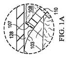
図1は、治療システム100の例示的実施形態の一部を立面図で示した断面図であり、治療システム100は本明細書に従って負圧治療、局所的処置溶液の滴下、およびデブリードマンを実現可能である。治療システム100はドレッシングおよび負圧源を含み得る。例えば、ドレッシング102は図1に示されるように負圧源104に流体結合され得る。図1Aは図1の治療システム100の一部の詳細図である。図1および1Aに示されるように、ドレッシング102は例えばカバー106と、例えば組織部位103などの組織部位に隣接または近接して位置付けるための組織界面107とを含む。いくつかの実施形態では、組織界面107はマニホルド、例えばマニホルド108であり得る。いくつかの実施形態では、組織界面107は、デブリードマン用具110などの組織除去用具であり得、デブリードマン用具110は、組織部位103に面するように適合された組織対向表面111と、例えばマニホルド108に面するように適合された反対表面113とを有する。さらに他の実施形態において、組織界面107はデブリードマン用具110およびマニホルド108の両方であり得る。治療システム100はまた、ドレッシング102におよび負圧源104に結合された、容器112などの滲出液容器を含み得る。いくつかの実施形態では、容器112は、コネクタ114およびチューブ116によってドレッシング102に流体結合され得、および容器112はチューブ118によって負圧源104に流体結合され得る。 FIG. 1 is a cross-sectional elevational view of a portion of an exemplary embodiment of a
いくつかの実施形態では、治療システム100は同じく滴下溶液源を含み得る。例えば、流体源120が、図1の例示的実施形態に示されるように、チューブ122およびコネクタ124によってドレッシング102に流体結合され得る。 In some embodiments,
概して、治療システム100の構成要素は、直接または間接的に結合され得る。例えば、負圧源104は容器112に直接結合され得、容器112を介してドレッシング102に間接的に結合され得る。構成要素は、構成要素間で流体(すなわち液体および/またはガス)を移送するための経路を提供するために、互いに流体結合され得る。 Generally, the components of
いくつかの実施形態では、例えば、構成要素は、チューブ116、チューブ118およびチューブ122などのチューブを介して流体結合され得る。「チューブ」は本明細書で使用される際、チューブ、パイプ、ホース、導管、または2つの端部間で流体を搬送するように作られた1つまたは複数の管腔を有する他の構造を広く指す。典型的にチューブは柔軟性を備えた細長い円筒状の構造であるが、形状および剛性は変化し得る。いくつかの実施形態では、構成要素は、追加的または代替的に、物理的近接性によって結合され得、単一構造物と一体的であるか、同一材料片から形成される。結合は状況によっては機械的、熱的、電気的または化学的な結合(化学結合など)も含み得る。 In some embodiments, for example, the components may be fluidly coupled via tubes such as
コネクタ114およびコネクタ124などの「コネクタ」は、チューブを、密封治療環境に流体結合するために使用され得る。負圧源によって生成された負圧はチューブを介してコネクタへ送達され得る。1つの説明に役立つ実施形態において、コネクタは、KCI(San Antonio,Texas)から入手可能なT.R.A.C.(登録商標)パッドまたはSensa T.R.A.C.(登録商標)パッドであり得る。1つの例示的実施形態において、コネクタ114は、負圧源104によって生成された負圧が、密封治療環境128へ送達されることを許容し得る。他の例示的実施形態において、コネクタはまた、ドレープを介して挿入されたチューブであり得る。1つの例示的実施形態において、コネクタ124は、流体源120によって供給された流体が、密封治療環境128へ送達されることを許容し得る。 “Connectors”, such as
処置の際、組織界面107は、組織部位103の内側、それを覆って、その上、またはその近くに配置され得る。カバー106は組織界面107を覆って配置され、組織部位の近くの組織に対して封じ付けられ得る。例えば、カバー106は、組織周辺(peritissue)としても知られる、組織部位の周囲の未損傷表皮に対して封じ付けられ得る。従って、ドレッシング102は、組織部位の近くに、外部環境から実質的に隔絶された密封治療環境128を提供することができ、負圧源104は、密封治療環境128内の圧力を低減することができる。密封治療環境128内の組織界面107を介して組織部位103全体に適用された負圧は、組織部位103内に大きい歪みおよび微小な歪みを誘発可能であり、ならびに滲出液および他の流体を組織部位103から取り除くことができ、滲出液および他の流体は容器112に集め、そこから適切に処理することができる。 During the procedure, the
密封治療環境内など、別の構成要素または場所内の圧力を低減するために負圧源を使用することの流体力学は数学的に複雑であり得る。しかしながら、負圧治療および滴下に適用可能な流体力学の基本原理は、当業者に一般的によく知られている。 The hydrodynamics of using a negative pressure source to reduce pressure in another component or location, such as in a sealed treatment environment, can be mathematically complex. However, the basic principles of hydrodynamics applicable to negative pressure therapy and drip are generally well known to those skilled in the art.
一般に、流体は流体経路に沿ってより低い圧力の方へ流れる。従って用語「下流」は典型的に、負圧源により近いまたは正圧源からより離れた、流体経路中の位置を指す。対照的に用語「上流]は典型的に、負圧源からより離れたまたは正圧源により近い、流体経路中の位置を指す。同様に、そのような基準枠で、流体の「入口」または「出口」の観点から、特定の特徴を記載することが便利であり得、また、圧力を低減するプロセスは、本明細書中、例えば、減圧を「送達する」、「分配する」または「生成する」として、説明に役立つように記載され得る。この向きは一般に、本明細書のシステムの様々な特徴および構成要素を記載するために仮定される。 Generally, fluid flows along the fluid path towards lower pressures. Thus, the term “downstream” typically refers to a position in the fluid path that is closer to the negative pressure source or further from the positive pressure source. In contrast, the term "upstream" typically refers to a location in the fluid path that is either further from the negative pressure source or closer to the positive pressure source. It may be convenient to describe a particular feature in terms of "outlet", and the process of reducing pressure is herein referred to as, for example, "delivering," "dispensing," or "generating" reduced pressure. Can be described as "doing". This orientation is generally assumed to describe various features and components of the systems herein.
組織部位103などの用語「組織部位」は、これに関連して、骨組織、脂肪組織、筋肉組織、神経組織、皮膚組織、血管組織、結合組織、軟骨、腱、または靭帯を含むがそれらに限定されない組織の上または中に位置する創傷または欠損を広く指す。創傷は、例えば慢性、急性、外傷性、亜急性、および裂開性創傷、部分的に厚い火傷、潰瘍(糖尿病性、圧迫性、または静脈不全性潰瘍など)、皮弁および移植片を含み得る。用語「組織部位」はまた、必ずしも創傷も欠損もないが追加的な組織の成長を追加または促進することが所望され得る領域である組織の領域を指す場合もある。例えば、負圧は、採取され得るまたは別の組織箇所へ移植され得る追加の組織を成長させるために特定の組織領域で使用され得る。 The term “tissue site”, such as
「負圧」は、ドレッシング102によって提供される密封治療環境の外部の局所的環境中の周囲圧力などの局所的周囲圧力より低い圧力を広く指す。多くの場合、局所的周囲圧力は、組織部位が置かれている大気圧でもあり得る。あるいは、圧力は、組織部位における組織に関連付けられる静水圧未満であり得る。特段の指示のない限り、本明細書に記載する圧力の値はゲージ圧力である。同様に、負圧の増大への言及は絶対圧力の低減を典型的に指し、一方で、負圧の低減は絶対圧力の増大を典型的に指す。 “Negative pressure” broadly refers to a pressure below local ambient pressure, such as ambient pressure in a local environment outside of the sealed therapeutic environment provided by the dressing 102. In many cases, the local ambient pressure can also be the atmospheric pressure at which the tissue site is located. Alternatively, the pressure may be below the hydrostatic pressure associated with the tissue at the tissue site. Unless otherwise indicated, all pressure values given herein are gauge pressures. Similarly, reference to increasing negative pressure typically refers to decreasing absolute pressure, while reducing negative pressure typically refers to increasing absolute pressure.
負圧源104などの負圧源は負圧の空気貯蔵庫であり得、または例えば陰圧ポンプ、吸引ポンプ、多くの医療施設で利用可能な壁の吸引ポートまたはミクロポンプなど、密閉体積内の圧力を低減可能な手動装置または電動装置であり得る。負圧源は、センサ、処理ユニット、警報指示器、メモリ、データベース、ソフトウェア、ディスプレイ装置、またはユーザインターフェースなど、負圧治療をさらに促進する他の構成要素内に収容されてもよく、またはそれらと併せて使用されてもよい。組織部位に適用される負圧の量および性質は治療要件に従って変化し得る一方、圧力は通常、−5mmHg(−667Pa)〜−500mmHg(−66.7kPa)の一般に低陰圧とも呼ばれる低い陰圧である。一般的な治療範囲は、−75mmHg(−9.9kPa)〜−300mmHg(−39.9kPa)である。 A negative pressure source, such as
組織界面107は組織部位と接触するように一般に適合可能である。組織界面107は組織部位と部分的または完全に接触し得る。組織部位が創傷の場合、例えば、組織界面107は部分的または完全に創傷を満たし得るか、または創傷の上に置かれ得る。組織界面107は、実行される処置の種類または組織部位の性質および寸法などの様々な要因に依存して、多くの形態を取り得、また多くの寸法、形状または厚さを有し得る。例えば、組織界面107の寸法および形状は深く不規則な形状の組織部位の輪郭に適合され得る。いくつかの実施形態では、組織界面107は、らせん状切断シートの形態で提供され得る。さらに、組織界面107の表面の何れもまたは全ては、組織部位に微小な歪みおよび応力を誘発できる平らでない、粗いまたは鋸歯状のプロファイルを有し得る。 The
いくつかの実施形態では、組織界面107は、マニホルド108などのマニホルドであり得る。「マニホルド」は、これに関連して、負圧下に組織部位にわたって流体を収集または分配するように適合された複数の経路を提供するあらゆる物体または構造物を広く含む。例えば、マニホルドは、源から負圧を受け入れ、その負圧を組織部位全体に複数の開口を介して分配するように適合され得、組織部位全体から流体を収集し、流体を源の方へ引く効果を有し得る。いくつかの実施形態では、流体経路は逆転されてもよく、または第2の流体経路が組織部位全体に流体を送達することを促すために提供されてもよい。 In some embodiments, the
いくつかの説明に役立つ実施形態では、マニホルドの経路は、組織部位にわたる流体の分配または収集を改善するために相互に接続されたチャネルであり得る。例えば、気泡質発泡体、連続気泡発泡体、網状発泡体、多孔性組織集積物およびガーゼまたはフェルトマットなどの他の多孔性材料は、相互接続された流体経路を形成するように適合された細孔、縁部および/または壁を一般に含む。液体、ゲルおよび他の発泡体も開口および流れチャネルを含み得るか、またはそれらを含むように硬化され得る。いくつかの説明に役立つ実施形態では、マニホルドは、均一(または準均一)に負圧を組織部位に分配するように適合された相互接続セルまたは細孔を有する多孔質発泡材料であり得る。発泡材料は疎水性または親水性の何れかであり得る。発泡材料の細孔径は指定された治療の要求に従って変化し得る。例えば、いくつかの実施形態では、マニホルド108は、約400マイクロメートル〜約600マイクロメートルの範囲の細孔径を有する発泡体であり得る。マニホルド108の引張強度も同じく、指定された治療の要求に従って変化し得る。例えば、発泡体の引張強度は、局所的処置溶液の滴下のために増大され得る。1つの非限定的な例では、マニホルド108は、Kinetic Concepts,Inc.(San Antonio,Texas)から入手可能なGranuFoam(登録商標)ドレッシングなどの連続気泡型網状ポリウレタン発泡体であり得、他の実施形態では、マニホルド108は、Kinetic Concepts,Inc.(San Antonio,Texas)から同じく入手可能なVeraFlo(登録商標)発泡体などの連続気泡型網状ポリウレタン発泡体であり得る。 In some illustrative embodiments, the manifold pathways may be interconnected channels to improve distribution or collection of fluid across the tissue site. For example, cellular foams, open celled foams, reticulated foams, porous tissue deposits and other porous materials such as gauze or felt mats are fine materials adapted to form interconnected fluid pathways. Generally includes holes, edges and/or walls. Liquids, gels and other foams may also include openings and flow channels, or may be cured to include them. In some illustrative embodiments, the manifold may be a porous foam material having interconnected cells or pores adapted to uniformly (or quasi-uniformly) distribute negative pressure to tissue sites. The foam material can be either hydrophobic or hydrophilic. The pore size of the foam material can vary according to the specified therapeutic requirements. For example, in some embodiments, the manifold 108 can be a foam having a pore size ranging from about 400 micrometers to about 600 micrometers. The tensile strength of the manifold 108 may also vary according to the specified therapeutic needs. For example, the tensile strength of the foam can be increased due to the instillation of the topical treatment solution. In one non-limiting example,
組織界面107が親水性材料から作られ得る例において、組織界面107も組織部位から流体を吸い上げ得る一方で、負圧を組織部位に分配し続ける。組織界面107の吸上げ特性は、毛管流または他の吸上げ機序によって組織部位から流体を引き離し得る。親水性発泡体の例は、Kinetic Concepts,Inc.(San Antonio,Texas)から入手可能なV.A.C.WhiteFoam(登録商標)ドレッシングなどのポリビニルアルコールの連続気泡発泡体である。他の親水性発泡体はポリエーテルから作製されたものを含み得る。親水特性を示す他の発泡体は、親水性をもたらすように処理またはコートされた疎水性発泡体を含む。 In the example where the
いくつかの実施形態では、組織界面107は、生体再吸収性材料から構成され得る。適切な生体再吸収性材料は、ポリ乳酸(PLA)およびポリグリコール酸(PGA)の高分子ブレンドを含み得るがそれらに限定されない。高分子ブレンドはポリカーボネート、ポリフマレートおよびカプララクトンも含み得るがそれらに限定されない。組織界面107は新しい細胞成長の足場としてさらに機能し得るか、または細胞成長を促進するために足場材料が組織界面107と組み合わせて使用され得る。足場は一般に、細胞成長のためのテンプレートを提供する3次元多孔性構造物など、細胞の成長または組織の形成を向上させるまたは促進するために使用される物体または構造物である。足場材料の説明に役立つ例は、リン酸カルシウム、コラーゲン、PLA/PGA、珊瑚状ヒドロキシアパタイト、カーボネート、または処理された同種移植材料を含む。 In some embodiments, the
いくつかの実施形態では、カバー106は、細菌遮断層および物理的外傷からの保護を提供し得る。カバー106はまた、蒸発損失を低減可能でありかつ2つの構成要素間、または治療環境と局所的外部環境との間など、2つの環境間に流体シールを提供可能な材料から構成されたシール部材であり得る。カバー106は例えば、所与の負圧源の負圧を組織部位で維持するのに適したシールを提供できる弾性フィルムまたは膜であり得る。いくつかの例示的な実施形態では、カバー106は、水蒸気に対し透過性であるが液体不透過性である、ポリウレタンフィルムなどの高分子ドレープであり得る。そのようなドレープは典型的に、約25マイクロメートル〜約50マイクロメートルの範囲内の厚さを有する。透過性材料に関して、その透過性は一般に、所望の負圧を維持できるのに十分に低くあるべきである。 In some embodiments, the
カバー106を、未損傷表皮、ガスケットまたは他のカバーなどの取付表面に取り付けるために取付装置が使用され得る。取付装置は多くの形態を取り得る。例えば取付装置は、シール部材の周囲、一部または全体に広がる医療的に許容可能な感圧性接着剤であり得る。いくつかの実施形態では例えば、カバー106の一部または全部が、約25グラム/平方メートル(gsm)〜約65gsmのコーティング重量を有するアクリル系接着剤でコートされ得る。シールを改善しかつ漏出を低減するために、より厚い接着剤、または接着剤の組合せが、いくつかの実施形態では適用され得る。取付装置の他の例示的実施形態は、両面テープ、糊、親水コロイド、ヒドロゲル、シリコーンゲルまたはオルガノゲルを含み得る。 A mounting device can be used to mount the
容器112は、滲出液または他の流体を組織部位から撤退させるために使用可能な容器、キャニスタ、パウチまたは他の貯蔵構成要素の代表である。多くの環境下では、流体を収集し貯蔵し廃棄するために、剛性容器が好ましいことがあり得、または要求され得る。他の環境下では、流体は剛性容器貯蔵器なしに適切に廃棄され得、再使用可能な容器が、負圧治療に関連する廃棄物および費用を削減することができる。 The
流体源120は、滴下治療用の溶液を提供可能な容器、キャニスタ、パウチ、バッグ、または他の貯蔵構成要素の代表であり得る。溶液の組成は指定された治療に従って変化し得るが、いくつかの処方に適切な溶液の例は、次亜塩素酸ベースの溶液、硝酸銀(0.5%)、硫黄ベースの溶液、ビグアナイド、カチオン性溶液、および等張液を含む。いくつかの実施形態では、流体源120などの流体源は、大気圧またはそれを超える圧力の流体貯蔵器であり得、または例えば密封治療環境128などの密封体積に流体を搬送できる、ポンプなどの手動または電動装置であり得る。いくつかの実施形態では、流体源は、ぜん動ポンプを含み得る。 The
一部の組織部位は、標準的な医療プロトコルに従って治癒しない可能性があり、壊死組織の領域を広げる可能性がある。壊死組織は、死組織の除去を制御する標準的な身体プロセスによって除去されることができる組織よりも早く組織を死なせた感染、毒または外傷の結果もたらされた死組織であり得る。ときに壊死組織は瘡蓋の形態であり得、瘡蓋は組織の粘性の液体を含み得る。一般に、瘡蓋は、組織内の炎症反応を刺激する細菌および真菌感染によってできる。瘡蓋はクリームイエロー色であり得、膿と呼ばれることもある。図1に示されるように、瘡蓋130などの瘡蓋は、組織部位103の全部または一部を覆い得る。壊死組織はまた、焼痂132などの焼痂を含み得る。焼痂132は、脱水し硬化した壊死組織の一部であり得る。焼痂132は火傷、外傷、壊疽、潰瘍、真菌感染、蜘蛛の咬傷、または炭疽病の結果であり得る。焼痂は外科的切除器具を使用せずに動かすことが困難であり得る。壊死組織は同じく厚い滲出物および線維素性の瘡蓋も含み得る。 Some tissue sites may not heal according to standard medical protocols and may extend the area of necrotic tissue. Necrotic tissue can be dead tissue resulting from an infection, poison, or trauma that killed the tissue faster than it can be removed by standard bodily processes that control the removal of dead tissue. Sometimes necrotic tissue may be in the form of a scab, which may include a viscous liquid of tissue. In general, scabs are the result of bacterial and fungal infections that stimulate an inflammatory response within the tissue. The scab may be cream yellow in color and is sometimes called pus. As shown in FIG. 1, a scab, such as
組織部位が壊死組織を発生する場合、組織部位はデブリードマンと称されるプロセスで処置され得る。デブリードマンは、厚い滲出物、線維素性瘡蓋、瘡蓋130または焼痂132などの死んだ、損傷したまたは感染した物質を組織部位から除去することを含み得る。いくつかのデブリードマンプロセスにおいて、壊死組織を除去するために機械的プロセスが使用される。機械的プロセスは、メスまたは鋭い刃を有する他の切断器具を使用して壊死組織を組織部位から切り離すことを含み得る。典型的に、組織部位のデブリードマンを実行する機械的プロセスは痛みを伴う場合があり、また、局所麻酔の適用を必要とする場合がある。 If the tissue site develops necrotic tissue, the tissue site may be treated with a process called debridement. Debridement may include removing dead, damaged or infected material such as thick exudates, fibrinous scabs,
デブリードマンはまた、自己融解プロセスによって実行され得る。自己融解プロセスは、壊死組織を軟化かつ液化するために酵素および組織部位によって生成された水分を使用することを伴い得る。典型的には壊死組織を有する組織部位を覆ってドレッシングが配置され得、それにより組織部位によって生成された流体が適所に残り、壊死組織を水和させ得るようにする。自己融解プロセスは無痛であり得るが、進行が遅く、多くの日数を要する場合がある。自己融解プロセスは進行が遅いため、多数回のドレッシング交換も伴い得る。いくつかの自己融解プロセスは負圧治療と組み合され得、それにより、壊死組織が水和されるとき、組織部位に適用される負圧が、除去された壊死組織を取り除き得るようにする。場合によっては、組織部位全体に負圧を分配するために組織部位に配置されたマニホルドが、自己融解プロセスによって崩壊した壊死組織で遮断または閉塞され得る。マニホルドが閉塞されると、負圧は壊死組織を取り除くことができない場合があり、これは自己融解プロセスの進行を遅くするかまたは停止する可能性がある。 Debridement can also be performed by an autolysis process. The autolysis process may involve the use of water produced by enzymes and tissue sites to soften and liquefy necrotic tissue. A dressing may be placed over the tissue site, which typically has necrotic tissue, so that the fluid produced by the tissue site remains in place and can hydrate the necrotic tissue. The autolysis process can be painless, but it is slow and can take many days. Due to the slow progress of the self-melting process, multiple dressing changes may also be involved. Some autolysis processes can be combined with negative pressure treatment, such that when necrotic tissue is hydrated, the negative pressure applied to the tissue site can remove the removed necrotic tissue. In some cases, a manifold placed at the tissue site to distribute negative pressure across the tissue site may be blocked or occluded with necrotic tissue that has collapsed by the autolysis process. When the manifold is occluded, negative pressure may not be able to clear the necrotic tissue, which may slow or stop the autolysis process.
デブリードマンはまた、酵素または他の剤を組織部位に加えることによって実行され得る。酵素によって組織は消化される。往々にして、酵素の配置および酵素が組織部位と接触する時間の長さの厳密な制御を維持しなければならない。必要とされるよりも長い間にわたり酵素が組織部位上に残される場合、酵素は多過ぎる組織を除去し、組織部位を汚染し、または患者の他の領域に運ばれ得る。患者の他の領域に運ばれると、酵素は未損傷組織を崩壊し、他の合併症を引き起こす可能性がある。 Debridement can also be performed by adding enzymes or other agents to the tissue site. The enzyme digests the tissue. Often, tight control of the placement of the enzyme and the length of time the enzyme is in contact with the tissue site must be maintained. If the enzyme is left on the tissue site for longer than needed, the enzyme can remove too much tissue, contaminate the tissue site, or be transported to other areas of the patient. When delivered to other areas of the patient, the enzyme can disrupt undamaged tissue and cause other complications.
これらおよび他の制限は、治療システム100によって対処され得る。治療システム100は負圧治療、滴下治療およびデブリードマンを提供することができる。例えば、治療システム100のいくつかの実施形態では、負圧源が、負圧治療のために負圧を組織部位に供給するために組織部位と流体結合され得る。いくつかの実施形態では、流体源が、滴下治療のために組織部位に治療流体を供給するために組織部位と流体結合され得る。いくつかの実施形態では、治療システム100は、組織部位に隣接して配置されたデブリードマン用具を含み得る。治療システム100のいくつかの実施形態では、デブリードマン用具は、壊死組織を有する組織部位の領域を創傷清拭するために、負圧治療および滴下治療で使用され得る。 These and other limitations may be addressed by
治療システム100は、瘡蓋130および焼痂132を有する組織部位103の上で使用され得る。いくつかの実施形態では、デブリードマン用具110は、デブリードマン用具110が瘡蓋130および焼痂132と接触するように、組織部位103に隣接して位置付けられ得る。いくつかの実施形態では、マニホルド108がデブリードマン用具110を覆って位置付けられ得る。他の実施形態では、組織部位103がデブリードマン用具110の深さと同程度の深さを有する場合、マニホルド108は使用されない場合がある。 The
いくつかの実施形態では、デブリードマン用具110は、実質的に平坦または実質的に平坦な本体であり得る。デブリードマン用具110は、厚さ134を有し得る。いくつかの実施形態では、厚さ134は約15mmであり得る。他の実施形態では、厚さ134は組織部位103の必要に応じて約15mmよりも薄いまたは厚い場合がある。いくつかの実施形態では、デブリードマン用具110の個々の部分は、厚さ134から最小限の許容誤差を有し得る。いくつかの実施形態では、厚さ134は約2mmの許容誤差を有し得る。デブリードマン用具110はデブリードマン用具110が組織部位103の表面の形状に合うことができるように柔軟性であり得る。 In some embodiments, the
いくつかの実施形態では、デブリードマン用具110は、スチレンエチレンブチレンスチレン(SEBS)コポリマーまたは熱可塑性ポリウレタン(TPU)などの熱可塑性エラストマー(TPE)から形成され得る。デブリードマン用具110はTPEまたはTPUの組合せシートによって形成され得る。いくつかの実施形態では、TPEまたはTPUのシートは互いに接合、溶接、接着または他の方法で結合され得る。例えば、いくつかの実施形態では、TPEまたはTPUのシートは放射熱、高周波溶接またはレーザ溶接を用いて溶接され得る。Supracor,Inc.、Hexacor,Ltd.、Hexcel Corp.およびEconocorp,Inc.が、デブリードマン用具110の形成に適したTPEまたはTPUシートを製造し得る。いくつかの実施形態では、約0.2mm〜約2.0mmの厚さを有するTPEまたはTPUのシートが、厚さ134を有する構造を形成するために使用され得る。いくつかの実施形態では、デブリードマン用具110は、スペーサーファブリックとも呼ばれる3Dテキスタイルから形成され得る。好適な3DテキスタイルはHeathcoat Fabrics,Ltd.、BaltexおよびMueller Textil Groupによって製造され得る。 In some embodiments, the
いくつかの実施形態では、デブリードマン用具110は発泡体から形成され得る。例えば、気泡質発泡体、連続気泡発泡体、網状発泡体、または多孔性組織集積物が、デブリードマン用具110を形成するために使用され得る。いくつかの実施形態では、デブリードマン用具110は、GranuFoam(登録商標)、grey foamまたはZotefoamから形成され得る。Grey foamは、約60細孔/インチ(ppi)を有するポリエステルポリウレタン発泡体であり得る。Zotefoamは独立気泡型架橋ポリオレフィン発泡体であり得る。1つの非限定的な例では、デブリードマン用具110は、Kinetic Concepts,Inc.(San Antonio,Texas)から入手可能なGranuFoam(登録商標)ドレッシングなどの連続気泡型網状ポリウレタン発泡体であり得、他の実施形態では、デブリードマン用具110は、Kinetic Concepts,Inc.(San Antonio,Texas)から同じく入手可能なV.A.C.VeraFlo(登録商標)発泡体などの連続気泡型網状ポリウレタン発泡体であり得る。 In some embodiments, the
いくつかの実施形態では、デブリードマン用具110は、周囲圧力で発泡体の密度を増大するために機械的または化学的に圧縮された発泡体から形成され得る。機械的または化学的に圧縮された発泡体は圧縮発泡体と称されることもある。圧縮発泡体は、圧縮状態にある発泡体の密度対未圧縮状態にある同じ発泡体の密度の比率として定義される硬度係数(firmness factor)(FF)によって特徴付けられ得る。例えば、5の硬度係数(FF)は、未圧縮状態にある同じ発泡体の密度よりも5倍高い密度を有する圧縮発泡体を指し得る。発泡体を機械的または化学的に圧縮することにより、周囲圧力における発泡体の厚さは、圧縮されていない同じ発泡体と比べて低減され得る。機械的または化学的な圧縮によって発泡体の厚さを低減することによって、発泡体の密度は向上され得、それにより発泡体の硬度係数(FF)が増大され得る。発泡体の硬度係数(FF)を増大することにより、発泡体の厚さと平行な方向における発泡体の剛性が増大され得る。例えば、デブリードマン用具110の硬度係数(FF)を増大することにより、デブリードマン用具110の厚さ134と平行な方向におけるデブリードマン用具110の剛性が増大され得る。いくつかの実施形態では、圧縮発泡体は圧縮されたGranuFoam(登録商標)であり得る。GranuFoam(登録商標)は未圧縮状態において約0.03グラム/センチメートル3(g/cm3)の密度を有し得る。GranuFoam(登録商標)が圧縮されて5の硬度係数(FF)を有する場合、GranuFoam(登録商標)は、GranuFoam(登録商標)の密度が約0.15g/cm3になるまで圧縮され得る。VeraFlo(登録商標)発泡体も同様に、最大5の硬度係数(FF)を有する圧縮発泡体を形成するように圧縮され得る。いくつかの実施形態では、デブリードマン用具110は約8mmの厚さを有し得、デブリードマン用具110が密封治療空間128内に配置されかつ約−125mmHgの負圧に曝される場合、デブリードマン用具110の厚さ134は約3mmを上回る可能性がある。In some embodiments, the
圧縮発泡体はフェルト発泡体と称されることもある。圧縮発泡体の場合のように、フェルト発泡体は、発泡体を永久的に圧縮して発泡体の密度を増大するために、熱成形プロセスを経る。フェルト発泡体も同じく、フェルト発泡体の硬度係数を、他の圧縮または未圧縮発泡体の硬度係数と比較することによって、他のフェルト発泡体または圧縮発泡体と比較され得る。一般に圧縮またはフェルト発泡体は1を超える硬度係数を有し得る。 Compressed foams are sometimes referred to as felt foams. As with compression foams, felt foams undergo a thermoforming process to permanently compress the foam and increase the density of the foam. Felt foams can also be compared to other felt or compressed foams by comparing the hardness coefficient of the felt foam to that of other compressed or uncompressed foams. Generally, compressed or felt foams can have a hardness coefficient greater than 1.
硬度係数(FF)は、圧縮発泡材料を非発泡材料と比較するためにも使用され得る。例えば、Supracor(登録商標)材料は、Supracor(登録商標)を圧縮発泡体と比較することを可能にする硬度係数(FF)を有し得る。いくつかの実施形態では、非発泡材料の硬度係数(FF)は、非発泡材料が同じ硬度係数を有する圧縮発泡体の剛性と等しい剛性を有することを示し得る。例えば、デブリードマン用具がSupracor(登録商標)から形成される場合、以下の表1に示されるように、デブリードマン用具は、3の硬度係数(FF)を有する圧縮されたGranuFoam(登録商標)材料の剛性と略同じである剛性を有し得る。 The hardness factor (FF) can also be used to compare compressed foam materials with non-foam materials. For example, a Supracor® material may have a hardness factor (FF) that allows Supracor® to be compared to a compressed foam. In some embodiments, the hardness factor (FF) of the non-foamed material may indicate that the non-foamed material has a stiffness equal to that of a compressed foam having the same hardness factor. For example, if the debridement device is formed from Supracor®, the debridement device will have a compressed GranuFoam® having a hardness factor (FF) of 3, as shown in Table 1 below. ) It may have a stiffness that is about the same as the stiffness of the material.
一般に、圧縮発泡体が負圧に曝される場合、圧縮発泡体は同様の未圧縮発泡体よりも少ない変形を示す。デブリードマン用具110が圧縮発泡体から形成される場合、デブリードマン用具110の厚さ134は、デブリードマン用具110が比較可能な未圧縮発泡体から形成される場合よりも少ない変形を示し得る。変形の低減は、硬度係数(FF)によって反映されるような増大した剛性によって引き起こされ得る。負圧の応力に曝される場合、圧縮発泡体から形成されたデブリードマン用具110は、未圧縮発泡体から形成されたデブリードマン用具110よりもわずかに平坦化し得る。結果として、負圧がデブリードマン用具110に適用されるとき、デブリードマン用具110の厚さ134と平行な方向におけるデブリードマン用具110の剛性は、デブリードマン用具110が他の方向、例えば厚さ134と垂直な方向においてより従順または圧縮可能になることを可能にする。圧縮発泡体を形成するために使用される発泡材料は疎水性または親水性の何れかであり得る。発泡材料の細孔径はデブリードマン用具110の要求および発泡体の圧縮量に従って変化し得る。例えば、いくつかの実施形態では、未圧縮発泡体は、約400マイクロメートル〜約600マイクロメートルの範囲の細孔径を有し得る。同じ発泡体が圧縮される場合、細孔径は発泡体が未圧縮状態にあるときよりも小さいことができる。 Generally, when a compressed foam is exposed to negative pressure, the compressed foam exhibits less deformation than a similar uncompressed foam. When the
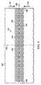
図2はデブリードマン用具110のいくつかの実施形態と関連付けられ得るさらなる詳細を示す平面図である。デブリードマン用具110は、デブリードマン用具110を貫通して伸びる壁148を形成するためにデブリードマン用具110を貫通して伸びる複数の穴140または穿孔を含み得る。いくつかの実施形態では、壁148はデブリードマン用具110の厚さ134と平行であり得る。他の実施形態では、壁148はデブリードマン用具110の組織対向表面111および反対表面113に対して略垂直であり得る。いくつかの実施形態では、穴140は示されるように六角形の形状を有し得る。他の実施形態では、穴140は円形、楕円形、三角形、正方形、不規則、または不定形の形状を有し得る。 FIG. 2 is a plan view showing additional details that may be associated with some embodiments of
いくつかの実施形態では、デブリードマン用具110は、第1の方向線136と、第1の方向線136に対して垂直な第2の方向線138とを有し得る。第1の方向線136および第2の方向線138はデブリードマン用具110の対称中心線であり得る。対称中心線は例えば、デブリードマン用具110の組織対向表面111または反対表面113を横切る仮想線であり得、デブリードマン用具110が対称中心線で折られる場合に穴140および壁148が同時に整列され得るような折れ線を定める。一般に、第1の方向線136および第2の方向線138はデブリードマン用具110を記載する際の補助となる。いくつかの実施形態では、第1の方向線136および第2の方向線138は、デブリードマン用具110の所望の収縮方向に言及するために使用され得る。例えば、所望の収縮方向は、第2の方向線138と平行でありかつ第1の方向線136と垂直であり得る。他の実施形態では、所望の収縮方向は、第1の方向線136と平行でありかつ第2の方向線138と垂直であり得る。さらに他の実施形態では、所望の収縮方向は、第1の方向線136および第2の方向線138の両方に対して垂直でない角度であり得る。一般に、デブリードマン用具110は、第2の方向線138が図1の瘡蓋130および焼痂132を横切って伸びるように、組織部位103に配置され得る。 In some embodiments, the
デブリードマン用具110は長手方向縁部144および横方向縁部146を含む略長方形の形状を有するように示されているが、デブリードマン用具110は他の形状を有し得る。例えば、デブリードマン用具110は、菱形、正方形、または円形の形状を有し得る。いくつかの実施形態では、デブリードマン用具110の形状は、処置される組織部位の種類に適応するように選択され得る。例えば、デブリードマン用具110は、楕円形または円形の組織部位に適応するように楕円形または円形の形状を有し得る。いくつかの実施形態では、第1の方向線136は、長手方向縁部144と平行であり得る。 Although the
より詳細に図3を参照すると、六角形の形状を有する1つの穴140が示されている。穴140は中心150および周辺152を含み得る。穴140は穿孔形状係数(perforation shape factor)(PSF)を有し得る。穿孔形状係数(PSF)は、第1の方向線136および第2の方向線138に対する穴140の方向性を示し得る。一般に、穿孔形状係数(PSF)は、所望の収縮方向と平行な穴140の最大長さの1/2対所望の収縮方向と垂直な穴140の最大長さの1/2の比率である。説明のため、所望の収縮方向は第2の方向線138と平行である。所望の収縮方向は創傷清拭力(debriding force)142によって示され得る。基準のため、穴140は、六角形の対向する頂点間に中心150を通って伸びかつ第1の方向線136と平行なX軸156と、六角形の対向する辺の間に中心150を通って伸びかつ第2の方向線138と平行なY軸154とを有し得る。穴140の穿孔形状係数(PSF)は、中心150から穴140の周辺152まで伸びるY軸154上の線区間158の、中心150から穴140の周辺152まで伸びるX軸156上の線区間160に対する比率として定義され得る。線区間158の長さが2.69mmでありかつ線区間160の長さが2.5mmである場合、穿孔形状係数(PSF)は2.69/2.5、すなわち約1.08であり得る。他の実施形態では、穴140は、穿孔形状係数(PSF)が約1.07または1.1であり得るように、第1の方向線136および第2の方向線138に対して方向付けられ得る。 Referring in more detail to FIG. 3, one
図4を参照すると、図1のデブリードマン用具110の一部が示されている。デブリードマン用具110は、平行な列のパターンで整列された複数の穴140を含み得る。平行な列のパターンは、穴140の第1列162、穴140の第2列164および穴140の第3列166を含み得る。隣接列、例えば第1列162および第2列164の穴140の中心150は、第1の方向線136に沿って第2の方向線138からオフセットされることによって特徴付けられ得る。いくつかの実施形態では、隣接列の中心を接続する線は、第1の方向線136と筋交角度(SA)を形成し得る。例えば、第1列162の第1の穴140Aは、中心150Aを有し得、第2列164の第2の穴140Bは中心150Bを有し得る。筋交線168は中心150Aを中心150Bと接続し得る。筋交線168は第1の方向線136と角度170を形成し得る。角度170はデブリードマン用具110の筋交角度(SA)であり得る。いくつかの実施形態では、筋交角度(SA)は約90°未満であり得る。他の実施形態では、筋交角度(SA)は第1の方向線136に対して約30°〜約70°であり得る。他の実施形態では、筋交角度(SA)は第1の方向線136から約66°であり得る。一般に、筋交角度(SA)が減少するにつれて第1の方向線136と平行な方向におけるデブリードマン用具110の剛性は増大し得る。第1の方向線136と平行なデブリードマン用具110の剛性を増大することは、第1の方向線136と垂直なデブリードマン用具110の圧縮性を増大し得る。その結果、負圧がデブリードマン用具110に適用される場合、デブリードマン用具110は第1の方向線136と垂直な方向においてより順応的または圧縮可能になり得る。第1の方向線136と垂直な方向におけるデブリードマン用具110の圧縮性を増大することによって、デブリードマン用具110は創傷清拭力142を組織部位103に適用するように圧潰し得、これについては以下でより詳細に記載する。 Referring to FIG. 4, a portion of the
いくつかの実施形態では、1つおきの列の穴140の中心150、例えば、第1列162の第1の穴140Aの中心150Aと、第3列166の穴140Cの中心150Cとは、長さ172だけ、第2の方向線138と平行に互いに離間され得る。いくつかの実施形態では、長さ172は穴140の有効直径よりも長いことができる。1つおきの列の穴140の中心150が長さ172だけ離される場合、第1の方向線136と平行な壁148は連続的であると見なされ得る。一般に、壁148は、壁148が不連続部分を有さない場合、すなわち穴140間で破断しない場合、連続的であり得る。 In some embodiments, the
穴140の形状に関わらず、デブリードマン用具110の穴140は、デブリードマン用具110内に、およびデブリードマン用具110の組織対向表面111と反対表面113との上に空隙を残し得、それにより、デブリードマン用具110の壁148のみが、組織部位103との接触に利用できる表面を伴って残るようにする。穴140の圧潰により、デブリードマン用具110が圧潰し第1の方向線136と垂直な方向に創傷清拭力142を生成するように壁148を最小化することが望ましいことがあり得る。しかしながら、負圧の適用を持続するために、デブリードマン用具110が脆弱になり過ぎるほど壁148を最小化しないことも望ましいことがあり得る。穴140の空隙パーセンテージ(VS)は、穴140によって生み出される組織対向表面111の空隙の体積または表面積の、デブリードマン用具110の組織対向表面111の全体体積または表面積に対するパーセンテージに等しいことができる。いくつかの実施形態では、空隙パーセンテージ(VS)は、約40%〜約60%であり得る。他の実施形態では、空隙パーセンテージ(VS)は、約55%であり得る。 Regardless of the shape of the
いくつかの実施形態では、穴140はデブリードマン用具110の成形中に形成され得る。他の実施形態では、穴140は、デブリードマン用具110が形成された後、デブリードマン用具110を打抜く、溶融する、または気化することによって形成され得る。例えば、穴140は、デブリードマン用具110の圧縮発泡体をレーザ打抜きすることによってデブリードマン用具110に形成され得る。いくつかの実施形態では、穴140の有効直径は穴140を通る粒子の流れを許容するように選択され得る。非円形領域の有効直径は、非円形領域と同じ表面領域を有する円形領域の直径として定義され得る。いくつかの実施形態では、各穴140は約3.5mmの有効直径を有し得る。他の実施形態では、各穴140は約5mm〜約20mmの有効直径を有し得る。穴140の有効直径は、デブリードマン用具110の壁148を形成する材料の空隙率と区別されるべきである。一般に、穴140の有効直径は、デブリードマン用具110を形成する材料の細孔の有効直径よりも桁違いに大きい。例えば、穴140の有効直径は約1mmを超え得るが、一方で壁148は約600マイクロメートル未満の細孔径を有するGranuFoam(登録商標)材料から形成され得る。いくつかの実施形態では、壁148の細孔は、材料全体を貫いて伸びる開口を形成しなくてもよい。 In some embodiments, the
ここで図2および4の両方を参照すると、穴140は、穴140の幾何学的形状と、第1の方向線136に対するデブリードマン用具110中の隣接列および1つおきの列間の穴140の整列とに依存してパターンを形成し得る。デブリードマン用具110が負圧に曝される場合、デブリードマン用具110の穴140は圧潰し得る。いくつかの実施形態では、空隙パーセンテージ(VS)、穿孔形状係数(PSF)、および筋交角度(SA)は、図5により詳細に示されるように、デブリードマン用具110が、第1の方向線136に対して垂直な第2の方向線138に沿って収縮することを引き起こし得る。デブリードマン用具110が組織部位103の上に配置される場合、図5により詳細に示されるように、デブリードマン用具110は第2の方向線138に沿って創傷清拭力142を生成し、デブリードマン用具110を収縮する。創傷清拭力142は以下の表1に記載されるように上記の因子を調整することによって最適化され得る。いくつかの実施形態では、穴140は六角形であり得、約66°の筋交角度(SA)、約55%の空隙パーセンテージ(VS)、約5の硬度係数(FF)、約1.07の穿孔形状係数(PSF)、および約5mmの有効直径を有し得る。デブリードマン用具110が約−125mmHgの負圧に曝される場合、デブリードマン用具110によって行使される創傷清拭力142は約13.3Nである。デブリードマン用具110の穴140の有効直径が10mmに増大される場合、創傷清拭力142は約7.5Nに低減される。 Referring now to both FIGS. 2 and 4, the
図5を参照すると、デブリードマン用具110は、創傷清拭力142によって示されるように、第2の位置、すなわち収縮位置にある。手術中、負圧は負圧源104によって密封治療環境128に適用される。負圧の適用に応答して、デブリードマン用具110は、図2に示される弛緩位置から図5に示される収縮位置へ収縮する。一般に、デブリードマン用具110の厚さ134は、実質的に同一に保たれる。負圧が、例えば負圧を通気することによって取り除かれると、デブリードマン用具110は弛緩位置へ再び拡張する。デブリードマン用具110が図5の収縮位置と図2の弛緩位置との間で循環される場合、デブリードマン用具110の組織対向表面111は、瘡蓋130および焼痂132を含む創傷から死組織または汚染組織を切り離すことによって、組織部位103を創傷清拭する。組織対向表面111と壁148の横断表面とによって形成された穴140のエッジ部分が、組織部位103を創傷清拭する切れ刃を形成し、負圧が適用されるとき、切断された組織が穴140およびマニホルド108を通過して出て容器112内へ入ることを可能にする。いくつかの実施形態では、切れ刃は、各穴140が、組織対向表面111とそこで交差する周辺152によって形成される。 Referring to FIG. 5, the
いくつかの実施形態では、治療システム100は循環治療を実現し得る。循環治療は、密封治療環境128に負圧を適用し、次にそこから負圧を解放することを交互に行い得る。いくつかの実施形態では、負圧は、密封治療環境128内の圧力が所定の治療圧力に達するまで密封治療環境128に適用され得る。負圧が密封治療環境128に適用される場合、デブリードマン用具110は図5に示されるように収縮する。いくつかの実施形態では、密封治療環境128は、例えば約10分など、所定の治療期間の間、治療圧力で保たれ得る。他の実施形態では、治療期間は、適切な負圧治療を組織部位103に適用するために、必要に応じてより長いまたはより短い場合がある。 In some embodiments,
治療期間の後、密封治療環境128は通気され得る。例えば、負圧源104は密封治療環境128を大気(不図示)と流体結合し得、密封治療環境128が周囲圧力に戻ることを可能にする。いくつかの実施形態では、負圧源104は密封治療環境128を約1分間にわたり通気し得る。他の実施形態では、負圧源104は密封治療環境128をより長いまたは短い期間、通気し得る。密封治療環境128を通気することにより密封治療環境128が周囲圧力に戻ることに応答して、デブリードマン用具110は拡張し、図2の弛緩位置へ戻る。デブリードマン用具110の収縮および拡張により、デブリードマン用具110の切れ刃は組織部位103を上に記載したように創傷清拭する。瘡蓋130および焼痂132を含む切断された組織の除去された部分は、負圧が負圧源104によって密封治療環境128に適用されるとき、穴140を通して取り除かれ得る。 After the treatment period, the sealed
いくつかの実施形態では、滴下治療が負圧治療と組み合され得る。例えば、負圧治療の治療期間の後、流体源120は、流体を密封治療環境128に供給するように動作し得る。いくつかの実施形態では、流体源120は、負圧源104が密封治療環境128を通気している間、流体を供給し得る。例えば、流体源120は、滴下流体を流体源120から密封治療環境128へ移動させるように構成されたポンプを含み得る。他の実施形態では、負圧源104は密封治療環境128を通気しなくてもよい。その代わりに、密封治療環境128内の負圧が、滴下流体を流体源120から密封治療環境128へ引き込むために使用される。 In some embodiments, drip therapy can be combined with negative pressure therapy. For example, after the treatment period of negative pressure treatment, the
いくつかの実施形態では、流体源120は、ある一定体積の流体を密封治療環境128に供給し得る。いくつかの実施形態では、ある一定体積の流体は、密封治療環境128の体積と同じであり得る。他の実施形態では、ある一定体積の流体は、滴下治療を適切に適用するために必要に応じて密封治療環境128未満であり得るかまたはそれを上回り得る。いくつかの実施形態では、流体源120によって供給される流体は、滞留時間の間、密封治療環境128に留まり得る。いくつかの実施形態では、滞留時間は約5分である。他の実施形態では、滞留時間は、組織部位103に滴下治療を適切に施すために必要に応じてより長いまたは短い場合がある。滞留時間は、治療サイクルの滞留期間とも称され得る。 In some embodiments, the
滞留時間の最後に、負圧源104は滴下流体を容器112内へ引き込むように作動され得、治療サイクルを完了する。滴下流体が負圧によって密封治療環境128から除去されるとき、負圧は同様に密封治療環境128に適用され得、別の治療サイクルを開始する。 At the end of the dwell time, the
負圧源104によって実現される治療の各サイクルにおいて、デブリードマン用具110は収縮および拡張され得る。治療の各サイクルで、デブリードマン用具110の組織対向表面111は、創傷清拭力142によって、組織部位103の対向表面全体に擦り付けられる。創傷清拭力142によるデブリードマン用具110の擦り付け作用により、穴140の切れ刃は瘡蓋130および焼痂132の一部を取り除く。治療の各後続サイクルで、瘡蓋130および焼痂132のさらなる部分が創傷清拭力142によって組織部位103から除去される。粒子状の瘡蓋130および焼痂132の取り除かれた部分は、負圧治療によって組織部位103から引き離されるのに十分に小さいことができる。滴下治療が同じく適用される場合、流体源120からの流体が、創傷清拭された組織の除去を同じく支援し得る。滴下治療はマニホルド108も清浄化し得、除去された瘡蓋130および焼痂132によるマニホルド108の閉塞を防止する。 In each cycle of treatment provided by the
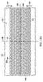
図6は、デブリードマン用具210のいくつかの実施形態に関連付けられ得るさらなる詳細を示す平面図である。デブリードマン用具210はデブリードマン用具110に類似したものであり得、図1〜5に関連して上に記載したように作動し得る。類似した要素は、200番台で示される類似の番号を有し得る。例えば、デブリードマン用具210は、長手方向縁部244と横方向縁部246とを含む略長方形の形状を有するように示されている。デブリードマン用具210は第1の方向線236と、第1の方向線236に対して垂直な第2の方向線238とを有し得る。いくつかの実施形態では、第1の方向線236および第2の方向線238は、デブリードマン用具210の所望の収縮方向に言及するために使用され得る。例えば、所望の収縮方向は、創傷清拭力142によって示されるように、第2の方向線238と平行でありかつ第1の方向線236と垂直であり得る。他の実施形態では、所望の収縮方向は、第2の方向線238と垂直でありかつ第1の方向線236と平行であり得る。さらに他の実施形態では、所望の収縮方向は、第2の方向線238および第1の方向線236の両方に対して非垂直であり得る。一般に、デブリードマン用具210は、デブリードマン用具210の組織対向表面211が瘡蓋130または焼痂132を有する組織部位103の部分を覆い得るように、組織部位103に配置され得る。デブリードマン用具210は、デブリードマン用具210を貫通して伸びる壁248を形成するためにデブリードマン用具210を貫通して伸びる複数の穴240または穿孔を含み得る。いくつかの実施形態では、壁248はデブリードマン用具210の厚さ234と平行である。壁248は、切れ刃を形成するために組織対向表面211と交差する横断表面を有し得る。いくつかの実施形態では、穴240は示されるように円形の形状を有し得る。 FIG. 6 is a plan view showing additional details that may be associated with some embodiments of
より詳細に図7を参照すると、円形の形状を有する1つの穴240が示されている。穴240は中心250、周辺252、および穿孔形状係数(PSF)を含み得る。基準のため、穴240は、中心250を通って伸びかつ第1の方向線236と平行なX軸256と、中心250を通って伸びかつ第2の方向線238と平行なY軸254とを有し得る。いくつかの実施形態では、穴240の穿孔形状係数(PSF)は、中心250から穴240の周辺252まで伸びるY軸254上の線区間258の、中心250から穴240の周辺252まで伸びるX軸256上の線区間260に対する比率として定義され得る。線区間258の長さが2.5mmでありかつ線区間260の長さが2.5mmである場合、穿孔形状係数(PSF)は2.5/2.5、すなわち約1であり得る。 Referring to FIG. 7 in more detail, one
図8を参照すると、図6のデブリードマン用具210の一部が示されている。デブリードマン用具210は、平行な列のパターンで整列された複数の穴240を含み得る。平行な列のパターンは、穴240の第1列262、穴240の第2列264および穴240の第3列266を含み得る。各穴240の図7のX軸256は図8の第1の方向線236と平行であり得る。隣接列、例えば第1列262および第2列264の穴240の中心250は、第1の方向線236に沿って第2の方向線238からオフセットされることによって特徴付けられ得る。いくつかの実施形態では、隣接列の中心を接続する線は、第1の方向線236と筋交角度(SA)を形成し得る。例えば、第1列262の第1の穴240Aは中心250Aを有し得、第2列264の第2の穴240Bは中心250Bを有し得る。筋交線268は中心250Aを中心250Bと接続し得る。筋交線268は第1の方向線236と角度270を形成し得る。角度270はデブリードマン用具210の筋交角度(SA)であり得る。いくつかの実施形態では、筋交角度(SA)は約90°未満であり得る。他の実施形態では、筋交角度(SA)は第1の方向線236に対して約30°〜約70°であり得る。上に記載したように、負圧がデブリードマン用具210に適用される場合、デブリードマン用具210は第1の方向線236と垂直な方向においてより順応的または圧縮可能になり得る。第1の方向線236と垂直な方向におけるデブリードマン用具210の圧縮性を増大することによって、デブリードマン用具210は創傷清拭力を組織部位103に適用するように圧潰し得、これについては以下でより詳細に記載する。 Referring to FIG. 8, a portion of the
いくつかの実施形態では、1つおきの列の穴240の中心250、例えば、第1列262の第1の穴240Aの中心250Aと、第3列266の穴240Cの中心250Cとは、長さ272だけ、第2の方向線238と平行に互いに離間され得る。いくつかの実施形態では、長さ272は穴240の有効直径よりも長いことができる。1つおきの列の穴240の中心250が長さ272だけ離される場合、第1の方向線236と平行な壁248は連続的であると見なされ得る。一般に、壁248は、壁248が不連続部分を有さない場合、すなわち穴240間で破断しない場合、連続的であり得る。 In some embodiments, the
穴240の形状に関わらず、デブリードマン用具210の穴240は、デブリードマン用具210内に、およびデブリードマン用具210の組織対向表面211上に空隙を残し得、それにより、デブリードマン用具210の壁248のみが、組織部位103との接触に利用できる表面を伴って残るようにする。穴240の圧潰により、デブリードマン用具210が圧潰し第1の方向線236と垂直な方向に創傷清拭力142を生成するように壁248を最小化することが望ましいことがあり得る。しかしながら、負圧の適用を持続するために、デブリードマン用具210が脆弱になり過ぎるほど壁248を最小化しないことも望ましいことがあり得る。穴240の空隙パーセンテージ(VS)は、穴240によって生み出される組織対向表面211の空隙の体積または表面積の、デブリードマン用具210の組織対向表面211の全体体積または表面積に対するパーセンテージに等しいことができる。いくつかの実施形態では、空隙パーセンテージ(VS)は、約40%〜約60%であり得る。他の実施形態では、空隙パーセンテージ(VS)は、約54%であり得る。 Regardless of the shape of the
いくつかの実施形態では、穴240の直径は穴240を通る粒子の流れを許容するように選択され得る。いくつかの実施形態では、各穴240は約5mmの直径を有し得る。他の実施形態では、各穴240は約3.5mm〜約20mmの有効直径を有し得る。 In some embodiments, the diameter of the
ここで図7および8の両方を参照すると、穴240は、穴240の幾何学的形状と、第1の方向線236に対するデブリードマン用具210中の隣接列および1つおきの列間の穴240の整列とに依存してパターンを形成し得る。デブリードマン用具210が負圧に曝される場合、デブリードマン用具210の穴240は圧潰し得る。いくつかの実施形態では、空隙パーセンテージ(VS)、穿孔形状係数(PSF)、および筋交角度(SA)は、デブリードマン用具210が、第1の方向線236に対して垂直な第2の方向線238に沿って圧潰することを引き起こし得る。創傷清拭力142は以下の表1に記載されるように上記の因子を調整することによって最適化され得る。いくつかの実施形態では、穴240は円形であり得、約37°の筋交角度(SA)、約54%の空隙パーセンテージ(VS)、約5の硬度係数(FF)、約1の穿孔形状係数(PSF)、および約5mmの直径を有し得る。デブリードマン用具210が約−125mmHgの負圧に曝される場合、デブリードマン用具210は約11.9Nの創傷清拭力142を行使する。デブリードマン用具210の穴240の直径が約20mmに増大される場合、空隙パーセンテージ(VS)は約52%に変化し、筋交角度(SA)は約52°に変化し、穿孔形状係数(PSF)および硬度係数(FF)は同じままであり、創傷清拭力142は約6.5Nに低減される。 Referring now to both FIGS. 7 and 8, the
図9Aは、デブリードマン用具310のいくつかの実施形態に関連付けられ得るさらなる詳細を示す平面図である。デブリードマン用具310はデブリードマン用具110に類似したものであり得、図1〜5に関連して上に記載したように作動し得る。類似した要素は、300番台で示される類似の番号を有し得る。デブリードマン用具310は組織部位103を覆い得る。いくつかの実施形態では、デブリードマン用具310は第1の方向線336と、第1の方向線336に対して垂直な第2の方向線338とを有し得る。いくつかの実施形態では、第1の方向線336および第2の方向線338は、デブリードマン用具310の所望の収縮方向に言及するために使用され得る。例えば、所望の収縮方向は、第2の方向線338と平行でありかつ第1の方向線336と垂直であり得る。他の実施形態では、所望の収縮方向は、第2の方向線338と垂直でありかつ第1の方向線336と平行であり得る。さらに他の実施形態では、所望の収縮方向は、第2の方向線338および第1の方向線336の両方に対して非垂直な角度であり得る。一般に、デブリードマン用具310は、デブリードマン用具310の組織対向表面311が瘡蓋130または焼痂132を有する組織部位103の部分を覆い得るように、組織部位103に配置され得る。デブリードマン用具310は、デブリードマン用具310を貫通して伸びる壁348を形成するためにデブリードマン用具310を貫通して伸びる複数の穴340または穿孔を含み得る。いくつかの実施形態では、壁348はデブリードマン用具310の厚さ334と平行である。壁348は、切れ刃を形成するために組織対向表面311と交差する横断表面を有し得る。いくつかの実施形態では、穴340は示されるように卵形の形状を有し得る。 FIG. 9A is a plan view showing additional details that may be associated with some embodiments of
より詳細に図10を参照すると、卵形の形状を有する1つの穴340が示されている。穴340は中心350、周辺352、および穿孔形状係数(PSF)を含み得る。基準のため、穴340は、中心350を通って伸びかつ第1の方向線336と平行なX軸356と、中心350を通って伸びかつ第2の方向線338と平行なY軸354とを有し得る。いくつかの実施形態では、穴340の穿孔形状係数(PSF)は、中心350から穴340の周辺352まで伸びるY軸354上の線区間358の、中心350から穴340の周辺352まで伸びるX軸356上の線区間360に対する比率として定義され得る。線区間358の長さが2.5mmでありかつ線区間360の長さが2.5mmである場合、穿孔形状係数(PSF)は2.5/2.5、すなわち約1であり得る。 Referring to FIG. 10 in more detail, one
図11を参照すると、穴340の主軸が第2の方向線338と平行になり穴340の副軸が第1の方向線336と平行になるように穴340が第1の方向線336および第2の方向線338に対して回転される場合、穿孔形状係数(PSF)が変化し得る。例えば、ここで穿孔形状係数(PSF)は、中心350から穴340の周辺352まで伸びるY軸354上の線区間376の、中心350から穴340の周辺352まで伸びるX軸356上の線区間378に対する比率である。線区間376の長さが5mmでありかつ線区間378の長さが2.5mmである場合、穿孔形状係数(PSF)は5/2.5、すなわち約2であり得る。 Referring to FIG. 11, the
図12を参照すると、穴340の主軸が第1の方向線336と平行になり穴340の副軸が第2の方向線338と平行になるように穴340が第1の方向線336および第2の方向線338に対して回転される場合、穿孔形状係数(PSF)が変化し得る。例えば、ここで穿孔形状係数(PSF)は、中心350から穴340の周辺352まで伸びるY軸354上の線区間380の、中心350から穴340の周辺352まで伸びるX軸356上の線区間382に対する比率である。線区間380の長さが2.5mmでありかつ線区間382の長さが5mmである場合、穿孔形状係数(PSF)は2.5/5、すなわち約1/2であり得る。 Referring to FIG. 12, the
図9Bを参照すると、図9Aのデブリードマン用具310の一部が示されている。デブリードマン用具310は、平行な列のパターンで整列された複数の穴340を含み得る。平行な列のパターンは、穴340の第1列362、穴340の第2列364および穴340の第3列366を含み得る。図10、11、および12の各穴340のX軸356は図9Bの第1の方向線336と平行であり得る。隣接列、例えば第1列362および第2列364の穴340の中心350は、第1の方向線336に沿って第2の方向線338からオフセットされることによって特徴付けられ得る。いくつかの実施形態では、隣接列の中心を接続する線は、第1の方向線336と筋交角度(SA)を形成し得る。例えば、第1列362の第1の穴340Aは中心350Aを有し得、第2列364の第2の穴340Bは中心350Bを有し得る。筋交線368は中心350Aを中心350Bと接続し得る。筋交線368は第1の方向線336と角度370を形成し得る。角度370はデブリードマン用具310の筋交角度(SA)であり得る。いくつかの実施形態では、筋交角度(SA)は約90°未満であり得る。他の実施形態では、筋交角度(SA)は第1の方向線336に対して約30°〜約70°であり得る。上に記載したように、負圧がデブリードマン用具310に適用される場合、デブリードマン用具310は第1の方向線336と垂直な方向においてより順応的または圧縮可能になり得る。第1の方向線336と垂直な方向におけるデブリードマン用具310の圧縮性を増大することによって、デブリードマン用具310は創傷清拭力142を組織部位103に適用するように圧潰し得、これについては以下でより詳細に記載する。 Referring to FIG. 9B, a portion of the
いくつかの実施形態では、1つおきの列の穴340の中心350、例えば、第1列362の第1の穴340Aの中心350Aと、第3列366の穴340Cの中心350Cとは、長さ372だけ、第2の方向線338と平行に互いに離間され得る。いくつかの実施形態では、長さ372は穴340の有効直径よりも長いことができる。1つおきの列の穴340の中心350が長さ372だけ離される場合、第1の方向線336と平行な壁348は連続的であると見なされ得る。一般に、壁348は、壁348が不連続部分を有さない場合、すなわち穴340間で破断しない場合、連続的であり得る。 In some embodiments, the
穴340の形状に関わらず、デブリードマン用具310の穴340は、デブリードマン用具310内に、およびデブリードマン用具310の組織対向表面311上に空隙を残し得、それにより、デブリードマン用具310の壁348のみが、組織部位103との接触に利用できる表面を伴って残るようにする。穴340の圧潰により、デブリードマン用具310が第1の方向線336と垂直な方向に創傷清拭力142を圧潰し得るように壁348を最小化することが望ましいことがあり得る。しかしながら、負圧の適用を持続するために、デブリードマン用具310が脆弱になり過ぎるほど壁348を最小化しないことも望ましいことがあり得る。穴340の空隙パーセンテージ(VS)は、穴340によって生み出される組織対向表面311の空隙の体積または表面積の、デブリードマン用具310の組織対向表面311の全体体積または表面積に対するパーセンテージに等しいことができる。いくつかの実施形態では、空隙パーセンテージ(VS)は、約40%〜約60%であり得る。他の実施形態では、空隙パーセンテージ(VS)は、約56%であり得る。 Regardless of the shape of the
いくつかの実施形態では、穴340の有効直径は穴340を通る粒子の流れを許容するように選択され得る。いくつかの実施形態では、各穴340は約7mmの有効直径を有し得る。他の実施形態では、各穴340は約2.5mm〜約20mmの有効直径を有し得る。 In some embodiments, the effective diameter of
ここで図9Aおよび9Bの両方を参照すると、穴340は、穴340の幾何学的形状と、第1の方向線336に対するデブリードマン用具310中の隣接列および1つおきの列間の穴340の整列とに依存してパターンを形成し得る。デブリードマン用具310が負圧に曝される場合、デブリードマン用具310の穴340は圧潰し得、それにより、デブリードマン用具310は、第1の方向線336に対して垂直な第2の方向線338に沿って圧潰する。デブリードマン用具310が組織部位103の上に配置される場合、デブリードマン用具310は第2の方向線338に沿って創傷清拭力142を生成し得、それによりデブリードマン用具310が同じ方向に収縮され組織部位103を創傷清拭するようにする。創傷清拭力142は以下の表1に記載されるように上記の因子を調整することによって最適化され得る。いくつかの実施形態では、穴340は卵形であり得、約47°の筋交角度(SA)、約56%の空隙パーセンテージ(VS)、約5の硬度係数(FF)、約1の穿孔形状係数(PSF)、および約7mmの有効直径を有し得る(ここで主軸は約10mmであり副軸は約5mmである)。デブリードマン用具310が約−125mmHgの負圧に曝される場合、デブリードマン用具310は約13.5Nの創傷清拭力142を行使する。 Referring now to both FIGS. 9A and 9B, the
図13Aは、デブリードマン用具410のいくつかの実施形態に関連付けられ得るさらなる詳細を示す平面図である。デブリードマン用具410はデブリードマン用具110に類似したものであり得、図1〜5に関連して上に記載したように作動し得る。類似した要素は、400番台で示される類似の番号を有し得る。例えば、デブリードマン用具410は長手方向縁部444および横方向縁部446を含む略長方形の形状を有するように示されている。デブリードマン用具410は組織部位103を覆い得る。いくつかの実施形態では、デブリードマン用具410は第1の方向線436と、第1の方向線436に対して垂直な第2の方向線438とを有し得る。いくつかの実施形態では、第1の方向線436および第2の方向線438は、デブリードマン用具410の所望の収縮方向に言及するために使用され得る。例えば、所望の収縮方向は、第2の方向線438と平行でありかつ第1の方向線436と垂直であり得る。他の実施形態では、所望の収縮方向は、第2の方向線438と垂直でありかつ第1の方向線436と平行であり得る。さらに他の実施形態では、所望の収縮方向は、第2の方向線438および第1の方向線436の両方に対して非垂直な角度であり得る。一般に、デブリードマン用具410は、デブリードマン用具410の組織対向表面411が瘡蓋130または焼痂132を有する組織部位103の部分を覆い得るように、組織部位103に配置され得る。デブリードマン用具410は、デブリードマン用具410を貫通して伸びる壁448を形成するためにデブリードマン用具410を貫通して伸びる複数の穴440または穿孔を含み得る。いくつかの実施形態では、壁448はデブリードマン用具410の厚さ434と平行である。壁448は、切れ刃を形成するために組織対向表面411と交差する横断表面を有し得る。いくつかの実施形態では、穴440は示されるように三角形の形状を有し得る。 FIG. 13A is a plan view showing additional details that may be associated with some embodiments of
より詳細に図14を参照すると、三角形の形状を有する1つの穴440が示されている。穴440は中心450、周辺452、および穿孔形状係数(PSF)を含み得る。いくつかの実施形態では、穴440は第1の頂点484、第2の頂点486および第3の頂点488を含み得る。基準のため、穴440は、中心450を通って伸びかつ第1の方向線436と平行なX軸456と、中心450を通って伸びかつ第2の方向線438と平行なY軸454とを有し得る。いくつかの実施形態では、穴440の穿孔形状係数(PSF)は、中心450から穴440の周辺452まで伸びるY軸454上の線区間458の、中心450から穴440の周辺452まで伸びるX軸456上の線区間460に対する比率として定義され得る。線区間458の長さが1.1mmでありかつ線区間460の長さが1mmである場合、穿孔形状係数(PSF)は1.1/1、すなわち約1.1であり得る。 Referring in more detail to FIG. 14, one
図13Bを参照すると、図13Aのデブリードマン用具410の一部が示されている。デブリードマン用具410は、平行な列のパターンで整列された複数の穴440を含み得る。平行な列のパターンは、穴440の第1列462、穴440の第2列464および穴440の第3列466を含み得る。各穴440の図14のX軸456は、図13Bの第1の方向線436と平行であり得る。いくつかの実施形態では、第1列462の第1の穴440Aは、第1の頂点484Aが第1の方向線436と、第1の頂点484Aの反対側の第1の穴440Aの脚部との間にあるように方向付けられ得る。第1列462の第1の穴440Aに隣接する穴440Cは、第1の頂点484Cが第1の穴440Aに対向して方向付けられ得るように方向付けられ得る。 Referring to FIG. 13B, a portion of the
同じ方向に方向付けられる第1の頂点484を有する隣接列、例えば第1列462および第2列464の穴440の中心450は、第1の方向線436に沿って第2の方向線438からオフセットされることによって特徴付けられ得る。いくつかの実施形態では、隣接列の中心450を接続する線は、第1の方向線436と筋交角度(SA)を形成し得る。例えば、第1列462の第1の穴440Aは中心450Aを有し得、第2列464の第2の穴440Bは中心450Bおよび第1の頂点484Bを有し得る。筋交線468は中心450Aを中心450Bと接続し得る。筋交線468は第1の方向線436と角度470を形成し得る。角度470はデブリードマン用具410の筋交角度(SA)であり得る。いくつかの実施形態では、筋交角度(SA)は約90°未満であり得る。他の実施形態では、筋交角度(SA)は第1の方向線436に対して約40°〜約70°であり得る。上に記載したように、負圧がデブリードマン用具410に適用される場合、デブリードマン用具410は第1の方向線436と垂直な方向においてより順応的または圧縮可能になり得る。第1の方向線436と垂直な方向におけるデブリードマン用具410の圧縮性を増大することによって、デブリードマン用具410は創傷清拭力142を組織部位103に適用するように圧潰し得、これについては以下でより詳細に記載する。 The
穴440の形状に関わらず、デブリードマン用具410の穴440は、デブリードマン用具410内に、およびデブリードマン用具410の組織対向表面411上に空隙を残し得、それにより、デブリードマン用具410の壁448のみが、組織部位103との接触に利用できる表面を伴って残るようにする。穴440の圧潰により、デブリードマン用具410が第1の方向線436と垂直な方向に創傷清拭力142を生成するように壁448を最小化することが望ましいことがあり得る。しかしながら、負圧の適用を持続するために、デブリードマン用具410が脆弱になり過ぎるほど壁448を最小化しないことも望ましいことがあり得る。穴440の空隙パーセンテージ(VS)は、穴440によって生み出される組織対向表面411の空隙の体積または表面積の、デブリードマン用具410の組織対向表面411の全体体積または表面積に対するパーセンテージに等しいことができる。いくつかの実施形態では、空隙パーセンテージ(VS)は、約40%〜約60%であり得る。他の実施形態では、空隙パーセンテージ(VS)は、約56%であり得る。 Regardless of the shape of the
いくつかの実施形態では、穴440の有効直径は穴440を通る粒子の流れを許容するように選択され得る。いくつかの実施形態では、各穴440は約7mmの有効直径を有し得る。他の実施形態では、各穴440は約2.5mm〜約20mmの有効直径を有し得る。 In some embodiments, the effective diameter of
ここで図13Aおよび13Bの両方を参照すると、穴440は、穴440の幾何学的形状と、第1の方向線436に対するデブリードマン用具410中の隣接列および1つおきの列間の穴440の整列とに依存してパターンを形成し得る。デブリードマン用具410が負圧に曝される場合、デブリードマン用具410の穴440は圧潰し得る。いくつかの実施形態では、空隙パーセンテージ(VS)、穿孔形状係数(PSF)、および筋交角度(SA)は、デブリードマン用具410が、第1の方向線436に対して垂直な第2の方向線438に沿って圧潰することを引き起こし得る。デブリードマン用具410が組織部位103の上に配置される場合、デブリードマン用具410は第2の方向線438に沿って創傷清拭力142を生成し得、それによりデブリードマン用具410が同じ方向に収縮されるようにする。創傷清拭力142は以下の表1に記載されるように上記の因子を調整することによって最適化され得る。いくつかの実施形態では、穴440は三角形であり得、約63°の筋交角度(SA)、約40%の空隙パーセンテージ(VS)、5の硬度係数(FF)、1.1の穿孔形状係数(PSF)、および約10mmの有効直径を有し得る。デブリードマン用具410が約−125mmHgの負圧に曝される場合、デブリードマン用具410は約13.5Nの創傷清拭力142を行使し得る。 Referring now to both FIGS. 13A and 13B, the
図15は、デブリードマン用具510のいくつかの実施形態に関連付けられ得るさらなる詳細を示す平面図である。デブリードマン用具510は図1〜5に関連して上に記載したデブリードマン用具110に類似したものであり得る。デブリードマン用具510はストライプ516およびストライプ518を含み得る。いくつかの実施形態では、デブリードマン用具510は、GranuFoam(登録商標)に似た発泡体から形成され得る。いくつかの実施形態では、ストライプ518は発泡体の圧縮部分によって形成され得、それによりストライプ516が第1の密度を有しストライプ518が第2の密度を有するようにする。いくつかの実施形態では、第2の密度は例えば第1の密度よりも高い。いくつかの実施形態では、第2の密度は第1の密度より約3倍〜約5倍高い密度であり得る。例えば、ストライプ516は未圧縮発泡体であり得、ストライプ518は約5の硬度係数を有する圧縮発泡体であり得る。一般に、ストライプ516はストライプ518よりも圧縮可能であり得る。いくつかの実施形態では、ストライプ516およびストライプ518は、組織部位に対して垂直に方向付けられ得、他の実施形態では、ストライプ516およびストライプ518は組織部位に対して水平に方向付けられ得る。さらに他の実施形態では、ストライプ516およびストライプ518は組織部位に対して斜めに方向付けられ得る。デブリードマン用具510の発泡体材料は、デブリードマン用具510の組織対向表面511に配置された発泡体材料中の細孔によって形成された切れ刃を有し得る。デブリードマン用具510が負圧下に置かれる場合、ストライプ516は、ストライプ518よりも先に圧潰し得る。いくつかの実施形態では、ストライプ516が圧潰する場合、デブリードマン用具510はストライプ516に対して垂直に収縮する。デブリードマン用具510が上に記載したように収縮状態と弛緩状態との間で循環される場合、細孔の切れ刃が上に記載したデブリードマン用具110の切れ刃と同様に組織を創傷清拭し得る。 FIG. 15 is a plan view showing additional details that may be associated with some embodiments of the
デブリードマン用具110などのデブリードマン用具によって生成される、創傷清拭力142などの創傷清拭力は、治療圧力の負圧を密封治療環境に適用することによって生成される圧縮力に関連付けられ得る。例えば創傷清拭力142は、密封治療環境128内の治療圧力(TP)と、デブリードマン用具110の圧縮係数(CF)と、デブリードマン用具110の表面積(A)組織対向表面111との積に比例し得る。その関係性は以下のように表される:
創傷清拭力α(TP*CF*A)A debriding force, such as
Debriding power α (TP* CF* A)
いくつかの実施形態では、治療圧力TPはN/m2で測定され、圧縮係数(CF)は無次元であり、面積(A)はm2で測定され、創傷清拭力はニュートン(N)で測定される。デブリードマン用具へ負圧を適用する結果としてもたらされる圧縮係数(CF)は、例えば、デブリードマン用具の空隙パーセンテージ(VS)と、デブリードマン用具の硬度係数(FF)と、デブリードマン用具中の穴の筋交角度(SA)と、デブリードマン用具中の穴の穿孔形状係数(PSF)との積に比例する無次元数であり得る。その関係性は以下のように表される:
圧縮係数(CF)α(VS*FF*sin(SA)*PSF)In some embodiments, the treatment pressure TP is measured in N/m2 , the compression factor (CF) is dimensionless, the area (A) is measured in m2 , and the debriding force is Newton (N). Measured in. The compression factor (CF) resulting from the application of negative pressure to the debridement device is, for example, the void percentage (VS) of the debridement device, the hardness factor (FF) of the debridement device, and the debridement device. It can be a dimensionless number that is proportional to the product of the bracing angle (SA) of the hole in the tool and the perforation shape factor (PSF) of the hole in the debridement tool. The relationship is expressed as:
Compression coefficient (CF) α (VS* FF* sin (SA)* PSF)
上記の式に基づいて、異なる形状の穴を有する異なる材料から形成されたデブリードマン用具を製造し、デブリードマン用具の創傷清拭力を決定するために試験した。各デブリードマン用具に関して、治療圧力TPは約−125mmHgであり、デブリードマン用具の寸法は約200mm×約53mmであり、その結果、デブリードマン用具の組織対向表面の表面積(A)は約106cm2、換言すると0.0106m2であった。上に記載した2つの等式に基づくと、3の硬度係数(FF)を有するSupracor(登録商標)デブリードマン用具110の創傷清拭力は約13.3であり、この際、Supracor(登録商標)デブリードマン用具110は、5mmの対向頂点間の距離を有する六角形の穴140と、1.07の穿孔形状係数(PSF)と、約66°の筋交角度(SA)と、約55%の空隙パーセンテージ(VS)とを有していた。同様に寸法決めされたGranuFoam(登録商標)デブリードマン用具110は、約9.1ニュートン(N)の創傷清拭力142を生成した。
いくつかの実施形態では、上に記載した式は、デブリードマン用具から創傷への力の移行による力の損失のために、創傷清拭力を正確に記載しない可能性がある。例えば、カバー106の弾性率および伸張、組織部位103の弾性率、組織部位103上のカバー106のすべり、およびデブリードマン用具110と組織部位103との間の摩擦が原因となって、創傷清拭力142の実際値は、創傷清拭力142の計算値未満になる可能性がある。 In some embodiments, the equations described above may not accurately describe the debriding force due to the loss of force due to the transfer of force from the debridement device to the wound. For example, due to the elastic modulus and extension of the
本明細書に記載したシステム、装置および方法は、著しい有利性を提供し得る。例えば、デブリードマン用具の機械的な擦り付け作用を、滴下および負圧治療の水和およびフラッシング作用と組み合わせることにより、組織部位の低痛または無痛デブリードマンが可能になり得る。本明細書に記載したようなデブリードマン用具はまた、他の機械的デブリードマンプロセスおよび酵素的デブリードマンプロセスと比較して、臨床医または他の助手による少ない監視量を必要とし得る。加えて、本明細書に記載したようなデブリードマン用具は、組織部位の自動デブリードマンの過程で生じ得るような除去された壊死組織による遮断がないことができる。 The systems, devices and methods described herein may offer significant advantages. For example, the mechanical rubbing action of a debridement device may be combined with the hydration and flushing actions of drip and negative pressure therapy to allow for a hypopainful or painless debridement of tissue sites. Debridement devices such as those described herein may also require less oversight by a clinician or other assistant as compared to other mechanical and enzymatic debridement processes. In addition, debridement devices as described herein may be free of obstructed necrotic tissue that may have occurred during the automatic debridement of tissue sites.
本明細書に記載したシステム、装置および方法は、いくつかの説明に役立つ実施形態で示される一方で、様々な変更形態および修正形態を受け入れることができることを当業者であれば認識するであろう。さらに、「または(or)」などの語を使用した様々な代替形態の記載は、文脈が明白に要求しない限り相互排他性を要求せず、また、不定冠詞「1つの(a)」または「1つの(an)」は、文脈が明白に要求しない限りその主体を単一の例に限定しない。 Those of skill in the art will recognize that the systems, devices and methods described herein are presented in a number of illustrative embodiments, but are susceptible to various changes and modifications. .. Further, the description of various alternative forms using terms such as "or" does not require mutual exclusivity unless the context clearly requires, and also the indefinite article "one (a)" or "1." An "an" does not limit the subject to a single instance unless the context clearly requires it.
付随する請求項は上に記載した主題の新規かつ発明的な態様を記載するが、それらの請求項は具体的に詳細に挙げられない追加の主題も包含し得る。例えば、特定の特徴、要素または態様は、新規かつ発明的な特徴を当業者にすでに知られているものから区別する必要のない場合、請求項から省略される場合がある。本明細書に記載した特徴、要素および態様はまた、付随する請求項によって定義される本発明の範囲から逸脱することなく組み合わされてもよく、または同一、均等または同様の目的を果たす代替的な特徴によって置き換えられてもよい。 Although the appended claims set forth novel and inventive aspects of the subject matter set forth above, those claims may also cover additional subject matter not specifically recited in detail. For example, particular features, elements or aspects may be omitted from the claims where it is not necessary to distinguish novel and inventive features from those already known to those skilled in the art. The features, elements and aspects described herein may also be combined without departing from the scope of the invention as defined by the appended claims or alternatives serving the same, equivalent or similar purpose. It may be replaced by a feature.
Claims (63)
Translated fromJapanese負圧を前記組織部位に送達するように適合されたマニホルドと、
負圧を負圧源から受け入れるために前記マニホルドおよび前記組織部位を覆う密封空間を形成するように適合されたカバーと、
前記マニホルドと前記組織部位との間に配置されるように適合され、かつ組織対向表面および反対表面であって、それらの間に伸びる複数の穴を含む組織対向表面および反対表面を有するデブリードマン用具であって、前記穴は壁によって互いに分離され、前記壁が、前記組織対向表面と前記反対表面との間に伸びる横断表面であって、前記組織対向表面と共に切れ刃を形成する横断表面を有し、前記穴が、前記負圧源からの負圧の適用に応答して弛緩位置から収縮位置へ前記穴が圧潰することを可能にする穿孔形状係数を有する、デブリードマン用具と
を含む、システムにおいて、
前記切れ刃が、前記デブリードマン用具の前記弛緩位置と前記収縮位置との間の移動に応答して前記組織部位を創傷清拭するように適合されることを特徴とするシステム。A system for debridement of a tissue site, the system comprising:
A manifold adapted to deliver negative pressure to the tissue site;
A cover adapted to form a sealed space over the manifold and the tissue site for receiving a negative pressure from a negative pressure source;
A debridement adapted to be placed between the manifold and the tissue site and having a tissue-facing surface and an opposing surface, the tissue-facing surface and the opposing surface including a plurality of holes extending therebetween. A tool, wherein the holes are separated from each other by a wall, the wall defining a transverse surface extending between the tissue-facing surface and the opposite surface, the transverse surface forming a cutting edge with the tissue-facing surface. A debridement tool having a perforation shape factor that allows the hole to collapse from a relaxed position to a contracted position in response to application of negative pressure from the negative pressure source. , In the system,
The system, wherein the cutting edge is adapted to debride the tissue site in response to movement of the debridement device between the relaxed and contracted positions.
前記穴が、前記弛緩位置から前記収縮位置へ前記穴が圧潰することを可能にする前記穿孔形状係数および筋交角度を有するように適合され、および
前記穴が、前記デブリードマン用具の対称中心線に対して略垂直に前記弛緩位置から前記収縮位置へ圧潰するように適合されることを特徴とするシステム。The system according to claim 1, wherein
The hole is adapted to have the perforation shape factor and a bracing angle that allow the hole to collapse from the relaxed position to the contracted position, and the hole is the center of symmetry of the debridement device. A system adapted to collapse from the relaxed position to the contracted position substantially perpendicular to a line.
組織対向表面と反対表面との間に伸びる壁によって互いに分離される複数の穿孔を含む組織対向表面および反対表面を有する組織界面であって、前記穿孔が、負圧源からの負圧の適用および除去に応答して前記穿孔を弛緩位置と収縮位置との間で圧潰するように適合された穿孔形状係数を有する、組織界面
を含む、装置において、
前記壁によって形成された前記穿孔の周辺が、前記組織界面の前記弛緩位置と前記収縮位置との間の移動に応答して前記組織部位を創傷清拭するように適合されることを特徴とする装置。A device for debridement of a tissue site, comprising:
A tissue interface havinga tissue facing surface and an opposite surface comprising a plurality of perforations separated from each other bya wallextending between thetissue facing surface and the opposite surface , the perforations comprising applying negative pressure from a negative pressure source and A device comprising a tissue interface having a perforation shape factor adapted to collapse the perforation between a relaxed position and a contracted position in response to removal.
The perimeter of the perforation formed by the wall is adapted to debride the tissue site in response to movement of the tissue interface between the relaxed position and the contracted position. apparatus.
前記穿孔が、前記穿孔を前記弛緩位置から前記収縮位置へ圧潰するように適合された前記穿孔形状係数および筋交角度を有し、および
前記穿孔が、前記組織界面の対称中心線に対して略垂直に前記弛緩位置から前記収縮位置へ圧潰するように適合されることを特徴とする装置。The device of claim 23, wherein
The perforation has the perforation shape factor and a bracing angle adapted to collapse the perforation from the relaxed position to the contracted position, and the perforation is substantially with respect to a symmetry centerline of the tissue interface. A device adapted to vertically collapse from the relaxed position to the contracted position.
負圧を前記組織部位に送達するように適合され、かつ第1の硬度係数を有するマニホルドと、
負圧源から負圧を受け入れるために前記マニホルドおよび前記組織部位を覆って密封空間を形成するように適合されたカバーと、
前記マニホルドと前記組織部位との間に位置付けられるように適合された組織界面であって、前記第1の硬度係数よりも大きい第2の硬度係数と、壁によって互いに分離される複数の穴とを有する組織界面と
を含み、
前記壁によって形成された前記複数の穴の周辺が、前記組織部位を創傷清拭するように適合されることを特徴とするシステム。In a system for treating a tissue site,
A manifold adapted to deliver a negative pressure to the tissue site and having a first hardness coefficient;
A cover adapted to form a sealed space over the manifold and the tissue site to receive negative pressure from a negative pressure source;
A tissue interface adapted to be positioned between the manifold and the tissue site, a second hardness coefficient greater than the first hardness coefficient, and a plurality of holes separated from each other by a wall.look including a tissue interfacewith,
A system wherein the perimeter of the plurality of holes formed by the wall is adapted to debride the tissue site .
Applications Claiming Priority (3)
| Application Number | Priority Date | Filing Date | Title |
|---|---|---|---|
| US201461991134P | 2014-05-09 | 2014-05-09 | |
| US61/991,134 | 2014-05-09 | ||
| PCT/US2015/030023WO2015172104A1 (en) | 2014-05-09 | 2015-05-08 | Debriding dressing for use with negative pressure and fluid instillation |
Related Child Applications (1)
| Application Number | Title | Priority Date | Filing Date |
|---|---|---|---|
| JP2020113823ADivisionJP7090667B2 (en) | 2014-05-09 | 2020-07-01 | Wound cleaning dressing for use with negative pressure and fluid dripping |
Publications (3)
| Publication Number | Publication Date |
|---|---|
| JP2017517312A JP2017517312A (en) | 2017-06-29 |
| JP2017517312A5 JP2017517312A5 (en) | 2018-06-14 |
| JP6728062B2true JP6728062B2 (en) | 2020-07-22 |
Family
ID=53267627
Family Applications (2)
| Application Number | Title | Priority Date | Filing Date |
|---|---|---|---|
| JP2016566815AActiveJP6728062B2 (en) | 2014-05-09 | 2015-05-08 | Debriding dressings for use with negative pressure and fluid drip |
| JP2020113823AActiveJP7090667B2 (en) | 2014-05-09 | 2020-07-01 | Wound cleaning dressing for use with negative pressure and fluid dripping |
Family Applications After (1)
| Application Number | Title | Priority Date | Filing Date |
|---|---|---|---|
| JP2020113823AActiveJP7090667B2 (en) | 2014-05-09 | 2020-07-01 | Wound cleaning dressing for use with negative pressure and fluid dripping |
Country Status (7)
| Country | Link |
|---|---|
| US (3) | US10143485B2 (en) |
| EP (4) | EP3821858B1 (en) |
| JP (2) | JP6728062B2 (en) |
| CN (3) | CN111134779B (en) |
| AU (3) | AU2015255719B2 (en) |
| CA (1) | CA2947298C (en) |
| WO (1) | WO2015172104A1 (en) |
Cited By (1)
| Publication number | Priority date | Publication date | Assignee | Title |
|---|---|---|---|---|
| JP2020049289A (en)* | 2014-05-09 | 2020-04-02 | ケーシーアイ ライセンシング インコーポレイテッド | Disruptive dressing for use with negative pressure and fluid dripping |
Families Citing this family (82)
| Publication number | Priority date | Publication date | Assignee | Title |
|---|---|---|---|---|
| US9421132B2 (en) | 2011-02-04 | 2016-08-23 | University Of Massachusetts | Negative pressure wound closure device |
| WO2013066426A2 (en) | 2011-06-24 | 2013-05-10 | Kci Licensing, Inc. | Reduced-pressure dressings employing tissue-fixation elements |
| AU2013264937B2 (en) | 2012-05-24 | 2018-04-19 | Smith & Nephew Inc. | Devices and methods for treating and closing wounds with negative pressure |
| MX369689B (en) | 2012-07-16 | 2019-11-19 | Smith & Nephew Inc | Negative pressure wound closure device. |
| US10124098B2 (en) | 2013-03-13 | 2018-11-13 | Smith & Nephew, Inc. | Negative pressure wound closure device and systems and methods of use in treating wounds with negative pressure |
| CN106170275B (en) | 2013-10-21 | 2021-05-07 | 史密夫和内修有限公司 | Negative pressure wound closure device |
| US10898217B2 (en) | 2014-05-09 | 2021-01-26 | Kci Licensing, Inc. | Dressing providing apertures with multiple orifice sizes for negative-pressure therapy |
| WO2015172108A1 (en) | 2014-05-09 | 2015-11-12 | Kci Licensing, Inc. | Dressing with contracting layer for linear tissue sites |
| DK3288508T3 (en) | 2015-04-27 | 2020-03-09 | Smith & Nephew | REDUCED PRESSURE DEVICES |
| AU2016254119A1 (en) | 2015-04-29 | 2017-10-05 | Smith & Nephew Inc. | Negative pressure wound closure device |
| US11471586B2 (en) | 2015-12-15 | 2022-10-18 | University Of Massachusetts | Negative pressure wound closure devices and methods |
| EP3426206B1 (en) | 2016-03-07 | 2023-05-10 | Smith & Nephew plc | Wound treatment apparatuses and methods with negative pressure source integrated into wound dressing |
| US11167074B2 (en) | 2016-03-17 | 2021-11-09 | Kcl Licensing, Inc. | Systems and methods for treating a tissue site using one manifold and multiple therapy units |
| CA3022184A1 (en) | 2016-04-26 | 2017-11-02 | Smith & Nephew Plc | Wound dressings and methods of use with integrated negative pressure source having a fluid ingress inhibition component |
| CA3038206A1 (en) | 2016-05-03 | 2017-11-09 | Smith & Nephew Plc | Optimizing power transfer to negative pressure sources in negative pressure therapy systems |
| WO2017191158A1 (en) | 2016-05-03 | 2017-11-09 | Smith & Nephew Plc | Systems and methods for driving negative pressure sources in negative pressure therapy systems |
| US11096831B2 (en) | 2016-05-03 | 2021-08-24 | Smith & Nephew Plc | Negative pressure wound therapy device activation and control |
| WO2018037075A1 (en) | 2016-08-25 | 2018-03-01 | Smith & Nephew Plc | Absorbent negative pressure wound therapy dressing |
| US11096832B2 (en) | 2016-09-27 | 2021-08-24 | Smith & Nephew Plc | Wound closure devices with dissolvable portions |
| EP3519001B1 (en) | 2016-09-30 | 2025-05-21 | Smith & Nephew plc | Negative pressure wound treatment apparatuses and methods with integrated electronics |
| CN110167495B (en) | 2016-11-02 | 2022-06-14 | 史密夫和内修有限公司 | Wound closure device |
| EP3551244A1 (en) | 2016-12-12 | 2019-10-16 | Smith & Nephew PLC | Pressure wound therapy status indication via external device |
| EP3592312B1 (en) | 2017-03-08 | 2024-01-10 | Smith & Nephew plc | Negative pressure wound therapy device control in presence of fault condition |
| JP7121050B2 (en) | 2017-05-09 | 2022-08-17 | スミス アンド ネフュー ピーエルシー | Redundant control of negative pressure wound therapy systems |
| WO2018226650A1 (en) | 2017-06-07 | 2018-12-13 | Kci Licensing, Inc. | Systems, apparatuses, and methods for negative-pressure treatment with reduced tissue in-growth |
| WO2018226691A1 (en) | 2017-06-07 | 2018-12-13 | Kci Licensing, Inc. | Methods for manufacturing and assembling dual material tissue interface for negative-pressure therapy |
| WO2018226707A1 (en) | 2017-06-07 | 2018-12-13 | Kci Licensing, Inc. | Composite dressings for improved granulation reduced maceration with negative-pressure treatment |
| AU2018282159A1 (en) | 2017-06-07 | 2019-12-19 | 3M Innovative Properties Company | Composite dressings for improved granulation and reduced maceration with negative-pressure treatment |
| JP7204685B2 (en) | 2017-06-07 | 2023-01-16 | スリーエム イノベイティブ プロパティズ カンパニー | A composite dressing that promotes granulation formation and reduces maceration in negative pressure therapy |
| WO2018226744A1 (en) | 2017-06-07 | 2018-12-13 | Kci Licensing, Inc. | Peel and place dressing for negative -pressure treatment |
| EP3634334B1 (en) | 2017-06-07 | 2023-05-24 | 3M Innovative Properties Company | Multi-layer wound filler for extended wear time |
| US10695227B2 (en) | 2017-06-07 | 2020-06-30 | Kci Licensing, Inc. | Methods for manufacturing and assembling dual material tissue interface for negative-pressure therapy |
| AU2018282188A1 (en) | 2017-06-07 | 2019-12-19 | 3M Innovative Properties Company | Tissue contact interface |
| WO2018229009A1 (en) | 2017-06-13 | 2018-12-20 | Smith & Nephew Plc | Wound closure device and method of use |
| EP3638169B1 (en) | 2017-06-13 | 2024-11-13 | Smith & Nephew PLC | Collapsible structure and method of use |
| US11123476B2 (en) | 2017-06-14 | 2021-09-21 | Smith & Nephew, Inc. | Fluid removal management and control of wound closure in wound therapy |
| WO2018231874A1 (en) | 2017-06-14 | 2018-12-20 | Smith & Nephew, Inc. | Control of wound closure and fluid removal management in wound therapy |
| AU2018285239B2 (en) | 2017-06-14 | 2023-09-21 | Smith & Nephew Plc | Collapsible sheet for wound closure and method of use |
| WO2018229011A1 (en) | 2017-06-14 | 2018-12-20 | Smith & Nephew Plc | Collapsible structure for wound closure and method of use |
| WO2019020544A1 (en) | 2017-07-27 | 2019-01-31 | Smith & Nephew Plc | Customizable wound closure device and method of use |
| US11590030B2 (en) | 2017-08-07 | 2023-02-28 | Smith & Nephew Plc | Wound closure device with protective layer and method of use |
| EP3675925A1 (en) | 2017-08-29 | 2020-07-08 | Smith & Nephew PLC | Systems and methods for monitoring wound closure |
| GB201718070D0 (en) | 2017-11-01 | 2017-12-13 | Smith & Nephew | Negative pressure wound treatment apparatuses and methods with integrated electronics |
| CA3074780A1 (en) | 2017-09-13 | 2019-03-21 | Smith & Nephew Plc | Negative pressure wound treatment apparatuses and methods with integrated electronics |
| RU2020113361A (en)* | 2017-09-20 | 2021-10-20 | Колопласт А/С | WOUND CARE DEVICE TO REMOVE DEAD TISSUE OF WOUNDS |
| US11432967B2 (en)* | 2017-10-23 | 2022-09-06 | Kci Licensing, Inc. | Fluid bridge for simultaneous application of negative pressure to multiple tissue sites |
| WO2019084006A1 (en) | 2017-10-23 | 2019-05-02 | Kci Licensing, Inc. | Low profile distribution components for wound therapy |
| JP7288901B2 (en)* | 2017-10-24 | 2023-06-08 | スリーエム イノベイティブ プロパティズ カンパニー | Wound dressing for debridement and system using same |
| GB201718054D0 (en) | 2017-11-01 | 2017-12-13 | Smith & Nephew | Sterilization of integrated negative pressure wound treatment apparatuses and sterilization methods |
| GB201718072D0 (en) | 2017-11-01 | 2017-12-13 | Smith & Nephew | Negative pressure wound treatment apparatuses and methods with integrated electronics |
| US11497653B2 (en) | 2017-11-01 | 2022-11-15 | Smith & Nephew Plc | Negative pressure wound treatment apparatuses and methods with integrated electronics |
| US20210077302A1 (en)* | 2018-01-04 | 2021-03-18 | Kci Licensing, Inc. | Peel And Place Dressing For Thick Exudate And Instillation |
| EP3735211B1 (en)* | 2018-01-04 | 2024-03-13 | Solventum Intellectual Properties Company | Peel and place dressing for thick exudate and instillation |
| US10624794B2 (en) | 2018-02-12 | 2020-04-21 | Healyx Labs, Inc. | Negative pressure wound therapy systems, devices, and methods |
| WO2019164618A1 (en)* | 2018-02-23 | 2019-08-29 | Kci Licensing, Inc. | Dressing with bolster for linear tissue sites |
| US11040127B2 (en) | 2018-04-09 | 2021-06-22 | Kci Licensing, Inc. | Abdominal dressing with mechanism for fascial closure |
| USD878609S1 (en) | 2018-04-09 | 2020-03-17 | Kci Licensing, Inc. | Compressive layer for abdominal wound dressing |
| EP3801416B1 (en)* | 2018-05-25 | 2024-07-10 | Solventum Intellectual Properties Company | Method and system for providing active tissue site debridement |
| US12053205B2 (en)* | 2018-05-25 | 2024-08-06 | Solventum Intellectual Properties Company | Method and system for providing active tissue site debridement |
| US12178687B2 (en) | 2018-05-25 | 2024-12-31 | Solventum Intellectual Properties Company | Method and system for providing active tissue site debridement |
| EP3829515A1 (en)* | 2018-08-01 | 2021-06-09 | KCI Licensing, Inc. | Soft-tissue treatment with negative pressure |
| CN112423800B (en) | 2018-08-03 | 2024-05-17 | 3M创新知识产权公司 | Wound treatment system with wound volume estimation |
| EP3840794B1 (en) | 2018-08-21 | 2023-10-11 | 3M Innovative Properties Company | System for utilizing pressure decay to determine available fluid capacity in a negative pressure dressing |
| USD898925S1 (en) | 2018-09-13 | 2020-10-13 | Smith & Nephew Plc | Medical dressing |
| WO2020056014A1 (en)* | 2018-09-14 | 2020-03-19 | Kci Licensing, Inc. | Differential collapse wound dressings |
| USD961782S1 (en) | 2018-10-23 | 2022-08-23 | Kci Licensing, Inc. | Low-profile fluid conductor for tissue therapy |
| JP7566755B2 (en)* | 2019-01-24 | 2024-10-15 | スリーエム イノベイティブ プロパティズ カンパニー | Variable density dressing |
| EP3914308B1 (en)* | 2019-01-25 | 2024-05-15 | Solventum Intellectual Properties Company | Systems for instillation purging |
| GB201903774D0 (en) | 2019-03-20 | 2019-05-01 | Smith & Nephew | Negative pressure wound treatment apparatuses and methods with integrated electronics |
| EP3946502A1 (en) | 2019-03-29 | 2022-02-09 | KCI Licensing, Inc. | Dressing with integrated pump and releasably coupled pump actuator |
| WO2020205445A1 (en)* | 2019-03-29 | 2020-10-08 | Kci Licensing, Inc. | Negative-pressure treatment with area stabilization |
| GB201907716D0 (en) | 2019-05-31 | 2019-07-17 | Smith & Nephew | Systems and methods for extending operational time of negative pressure wound treatment apparatuses |
| CN110338867A (en)* | 2019-06-26 | 2019-10-18 | 万绵水 | Electrostatic spinning Wound dressing and its processing method containing dihydroquercetin |
| WO2020263473A1 (en)* | 2019-06-26 | 2020-12-30 | Kci Licensing, Inc. | Dressing including differential lateral contraction capability |
| EP4007552B1 (en)* | 2019-08-01 | 2025-03-19 | Solventum Intellectual Properties Company | Hand dressing for use with negative pressure wound therapy |
| US12409072B2 (en) | 2019-12-05 | 2025-09-09 | Kci Manufacturing Unlimited Company | Multi-layer negative pressure incisional wound therapy dressing |
| US20220409801A1 (en)* | 2019-12-13 | 2022-12-29 | Kci Licensing, Inc. | Conformable dressing for negative-pressure treatment of large areas |
| JP2023536800A (en)* | 2020-07-09 | 2023-08-30 | ケーシーアイ ライセンシング インコーポレイテッド | Tissue interface for tissue debridement |
| CN116547017A (en)* | 2020-08-21 | 2023-08-04 | 凯希制造无限公司 | Wound interface system with integral contact surface |
| EP4251110A4 (en)* | 2020-11-24 | 2024-10-23 | Aroa Biosurgery Limited | BANDAGE |
| JP2024518367A (en) | 2021-05-06 | 2024-05-01 | ケーシーアイ マニュファクチャリング アンリミテッド カンパニー | Bioabsorbable, dispersible, rapidly deployable wound interface |
| CN114622334B (en)* | 2022-04-29 | 2024-01-23 | 青岛全季服饰有限公司 | Breathable ultraviolet-proof fabric and preparation method thereof |
Family Cites Families (149)
| Publication number | Priority date | Publication date | Assignee | Title |
|---|---|---|---|---|
| US1355846A (en) | 1920-02-06 | 1920-10-19 | David A Rannells | Medical appliance |
| US2547758A (en) | 1949-01-05 | 1951-04-03 | Wilmer B Keeling | Instrument for treating the male urethra |
| US2632443A (en) | 1949-04-18 | 1953-03-24 | Eleanor P Lesher | Surgical dressing |
| GB692578A (en) | 1949-09-13 | 1953-06-10 | Minnesota Mining & Mfg | Improvements in or relating to drape sheets for surgical use |
| US2682873A (en) | 1952-07-30 | 1954-07-06 | Johnson & Johnson | General purpose protective dressing |
| NL189176B (en) | 1956-07-13 | 1900-01-01 | Hisamitsu Pharmaceutical Co | PLASTER BASED ON A SYNTHETIC RUBBER. |
| US2969057A (en) | 1957-11-04 | 1961-01-24 | Brady Co W H | Nematodic swab |
| US3066672A (en) | 1960-09-27 | 1962-12-04 | Jr William H Crosby | Method and apparatus for serial sampling of intestinal juice |
| US3367332A (en) | 1965-08-27 | 1968-02-06 | Gen Electric | Product and process for establishing a sterile area of skin |
| US3520300A (en) | 1967-03-15 | 1970-07-14 | Amp Inc | Surgical sponge and suction device |
| US3568675A (en) | 1968-08-30 | 1971-03-09 | Clyde B Harvey | Fistula and penetrating wound dressing |
| US3682180A (en) | 1970-06-08 | 1972-08-08 | Coilform Co Inc | Drain clip for surgical drain |
| BE789293Q (en) | 1970-12-07 | 1973-01-15 | Parke Davis & Co | MEDICO-SURGICAL DRESSING FOR BURNS AND SIMILAR LESIONS |
| US3826254A (en) | 1973-02-26 | 1974-07-30 | Verco Ind | Needle or catheter retaining appliance |
| DE2527706A1 (en) | 1975-06-21 | 1976-12-30 | Hanfried Dr Med Weigand | DEVICE FOR THE INTRODUCTION OF CONTRAST AGENTS INTO AN ARTIFICIAL INTESTINAL OUTLET |
| DE2640413C3 (en) | 1976-09-08 | 1980-03-27 | Richard Wolf Gmbh, 7134 Knittlingen | Catheter monitor |
| NL7710909A (en) | 1976-10-08 | 1978-04-11 | Smith & Nephew | COMPOSITE STRAPS. |
| GB1562244A (en) | 1976-11-11 | 1980-03-05 | Lock P M | Wound dressing materials |
| US4080970A (en) | 1976-11-17 | 1978-03-28 | Miller Thomas J | Post-operative combination dressing and internal drain tube with external shield and tube connector |
| US4139004A (en) | 1977-02-17 | 1979-02-13 | Gonzalez Jr Harry | Bandage apparatus for treating burns |
| US4184510A (en) | 1977-03-15 | 1980-01-22 | Fibra-Sonics, Inc. | Valued device for controlling vacuum in surgery |
| US4165748A (en) | 1977-11-07 | 1979-08-28 | Johnson Melissa C | Catheter tube holder |
| US4245637A (en) | 1978-07-10 | 1981-01-20 | Nichols Robert L | Shutoff valve sleeve |
| SE414994B (en) | 1978-11-28 | 1980-09-01 | Landstingens Inkopscentral | VENKATETERFORBAND |
| GB2047543B (en) | 1978-12-06 | 1983-04-20 | Svedman Paul | Device for treating tissues for example skin |
| US4266545A (en) | 1979-04-06 | 1981-05-12 | Moss James P | Portable suction device for collecting fluids from a closed wound |
| US4284079A (en) | 1979-06-28 | 1981-08-18 | Adair Edwin Lloyd | Method for applying a male incontinence device |
| US4261363A (en) | 1979-11-09 | 1981-04-14 | C. R. Bard, Inc. | Retention clips for body fluid drains |
| US4569348A (en) | 1980-02-22 | 1986-02-11 | Velcro Usa Inc. | Catheter tube holder strap |
| WO1981002516A1 (en) | 1980-03-11 | 1981-09-17 | E Schmid | Cushion for holding an element of grafted skin |
| US4297995A (en) | 1980-06-03 | 1981-11-03 | Key Pharmaceuticals, Inc. | Bandage containing attachment post |
| US4333468A (en) | 1980-08-18 | 1982-06-08 | Geist Robert W | Mesentery tube holder apparatus |
| US4465485A (en) | 1981-03-06 | 1984-08-14 | Becton, Dickinson And Company | Suction canister with unitary shut-off valve and filter features |
| US4392853A (en) | 1981-03-16 | 1983-07-12 | Rudolph Muto | Sterile assembly for protecting and fastening an indwelling device |
| US4373519A (en) | 1981-06-26 | 1983-02-15 | Minnesota Mining And Manufacturing Company | Composite wound dressing |
| US4392858A (en) | 1981-07-16 | 1983-07-12 | Sherwood Medical Company | Wound drainage device |
| US4419097A (en) | 1981-07-31 | 1983-12-06 | Rexar Industries, Inc. | Attachment for catheter tube |
| AU550575B2 (en) | 1981-08-07 | 1986-03-27 | Richard Christian Wright | Wound drainage device |
| SE429197B (en) | 1981-10-14 | 1983-08-22 | Frese Nielsen | SAR TREATMENT DEVICE |
| DE3146266A1 (en) | 1981-11-21 | 1983-06-01 | B. Braun Melsungen Ag, 3508 Melsungen | COMBINED DEVICE FOR A MEDICAL SUCTION DRAINAGE |
| US4551139A (en) | 1982-02-08 | 1985-11-05 | Marion Laboratories, Inc. | Method and apparatus for burn wound treatment |
| US4475909A (en) | 1982-05-06 | 1984-10-09 | Eisenberg Melvin I | Male urinary device and method for applying the device |
| EP0100148B1 (en) | 1982-07-06 | 1986-01-08 | Dow Corning Limited | Medical-surgical dressing and a process for the production thereof |
| NZ206837A (en) | 1983-01-27 | 1986-08-08 | Johnson & Johnson Prod Inc | Thin film adhesive dressing:backing material in three sections |
| US4548202A (en) | 1983-06-20 | 1985-10-22 | Ethicon, Inc. | Mesh tissue fasteners |
| US4540412A (en) | 1983-07-14 | 1985-09-10 | The Kendall Company | Device for moist heat therapy |
| US4543100A (en) | 1983-11-01 | 1985-09-24 | Brodsky Stuart A | Catheter and drain tube retainer |
| US4525374A (en) | 1984-02-27 | 1985-06-25 | Manresa, Inc. | Treating hydrophobic filters to render them hydrophilic |
| CA1286177C (en) | 1984-05-03 | 1991-07-16 | Smith And Nephew Associated Companies Plc | Adhesive wound dressing |
| US4897081A (en) | 1984-05-25 | 1990-01-30 | Thermedics Inc. | Percutaneous access device |
| US5215522A (en) | 1984-07-23 | 1993-06-01 | Ballard Medical Products | Single use medical aspirating device and method |
| GB8419745D0 (en) | 1984-08-02 | 1984-09-05 | Smith & Nephew Ass | Wound dressing |
| US4872450A (en) | 1984-08-17 | 1989-10-10 | Austad Eric D | Wound dressing and method of forming same |
| US4826494A (en) | 1984-11-09 | 1989-05-02 | Stryker Corporation | Vacuum wound drainage system |
| US4655754A (en) | 1984-11-09 | 1987-04-07 | Stryker Corporation | Vacuum wound drainage system and lipids baffle therefor |
| US4605399A (en) | 1984-12-04 | 1986-08-12 | Complex, Inc. | Transdermal infusion device |
| US5037397A (en) | 1985-05-03 | 1991-08-06 | Medical Distributors, Inc. | Universal clamp |
| US4640688A (en) | 1985-08-23 | 1987-02-03 | Mentor Corporation | Urine collection catheter |
| US4710165A (en) | 1985-09-16 | 1987-12-01 | Mcneil Charles B | Wearable, variable rate suction/collection device |
| US4758220A (en) | 1985-09-26 | 1988-07-19 | Alcon Laboratories, Inc. | Surgical cassette proximity sensing and latching apparatus |
| US4733659A (en) | 1986-01-17 | 1988-03-29 | Seton Company | Foam bandage |
| EP0256060A1 (en) | 1986-01-31 | 1988-02-24 | OSMOND, Roger L. W. | Suction system for wound and gastro-intestinal drainage |
| US4838883A (en) | 1986-03-07 | 1989-06-13 | Nissho Corporation | Urine-collecting device |
| JPS62281965A (en) | 1986-05-29 | 1987-12-07 | テルモ株式会社 | Catheter and catheter fixing member |
| GB8621884D0 (en) | 1986-09-11 | 1986-10-15 | Bard Ltd | Catheter applicator |
| GB2195255B (en) | 1986-09-30 | 1991-05-01 | Vacutec Uk Limited | Apparatus for vacuum treatment of an epidermal surface |
| US4743232A (en) | 1986-10-06 | 1988-05-10 | The Clinipad Corporation | Package assembly for plastic film bandage |
| DE3634569A1 (en) | 1986-10-10 | 1988-04-21 | Sachse Hans E | CONDOM CATHETER, A URINE TUBE CATHETER FOR PREVENTING RISING INFECTIONS |
| JPS63135179A (en) | 1986-11-26 | 1988-06-07 | 立花 俊郎 | Subcataneous drug administration set |
| GB8628564D0 (en) | 1986-11-28 | 1987-01-07 | Smiths Industries Plc | Anti-foaming agent suction apparatus |
| GB8706116D0 (en) | 1987-03-14 | 1987-04-15 | Smith & Nephew Ass | Adhesive dressings |
| US4787888A (en) | 1987-06-01 | 1988-11-29 | University Of Connecticut | Disposable piezoelectric polymer bandage for percutaneous delivery of drugs and method for such percutaneous delivery (a) |
| US4863449A (en) | 1987-07-06 | 1989-09-05 | Hollister Incorporated | Adhesive-lined elastic condom cathether |
| US5176663A (en) | 1987-12-02 | 1993-01-05 | Pal Svedman | Dressing having pad with compressibility limiting elements |
| US4906240A (en) | 1988-02-01 | 1990-03-06 | Matrix Medica, Inc. | Adhesive-faced porous absorbent sheet and method of making same |
| US4985019A (en) | 1988-03-11 | 1991-01-15 | Michelson Gary K | X-ray marker |
| GB8812803D0 (en) | 1988-05-28 | 1988-06-29 | Smiths Industries Plc | Medico-surgical containers |
| US4919654A (en) | 1988-08-03 | 1990-04-24 | Kalt Medical Corporation | IV clamp with membrane |
| US5000741A (en) | 1988-08-22 | 1991-03-19 | Kalt Medical Corporation | Transparent tracheostomy tube dressing |
| US5059596A (en) | 1989-01-16 | 1991-10-22 | Roussel Uclaf | Azabicyclo compounds |
| GB8906100D0 (en) | 1989-03-16 | 1989-04-26 | Smith & Nephew | Laminates |
| US4969880A (en) | 1989-04-03 | 1990-11-13 | Zamierowski David S | Wound dressing and treatment method |
| US5261893A (en) | 1989-04-03 | 1993-11-16 | Zamierowski David S | Fastening system and method |
| US5100396A (en) | 1989-04-03 | 1992-03-31 | Zamierowski David S | Fluidic connection system and method |
| US5527293A (en) | 1989-04-03 | 1996-06-18 | Kinetic Concepts, Inc. | Fastening system and method |
| JP2719671B2 (en) | 1989-07-11 | 1998-02-25 | 日本ゼオン株式会社 | Wound dressing |
| US5358494A (en) | 1989-07-11 | 1994-10-25 | Svedman Paul | Irrigation dressing |
| US5232453A (en) | 1989-07-14 | 1993-08-03 | E. R. Squibb & Sons, Inc. | Catheter holder |
| GB2235877A (en) | 1989-09-18 | 1991-03-20 | Antonio Talluri | Closed wound suction apparatus |
| US5134994A (en) | 1990-02-12 | 1992-08-04 | Say Sam L | Field aspirator in a soft pack with externally mounted container |
| US5092858A (en) | 1990-03-20 | 1992-03-03 | Becton, Dickinson And Company | Liquid gelling agent distributor device |
| US5149331A (en) | 1991-05-03 | 1992-09-22 | Ariel Ferdman | Method and device for wound closure |
| US5278100A (en) | 1991-11-08 | 1994-01-11 | Micron Technology, Inc. | Chemical vapor deposition technique for depositing titanium silicide on semiconductor wafers |
| US5645081A (en) | 1991-11-14 | 1997-07-08 | Wake Forest University | Method of treating tissue damage and apparatus for same |
| US5636643A (en) | 1991-11-14 | 1997-06-10 | Wake Forest University | Wound treatment employing reduced pressure |
| US5279550A (en) | 1991-12-19 | 1994-01-18 | Gish Biomedical, Inc. | Orthopedic autotransfusion system |
| US5167613A (en) | 1992-03-23 | 1992-12-01 | The Kendall Company | Composite vented wound dressing |
| FR2690617B1 (en) | 1992-04-29 | 1994-06-24 | Cbh Textile | TRANSPARENT ADHESIVE DRESSING. |
| DE4306478A1 (en) | 1993-03-02 | 1994-09-08 | Wolfgang Dr Wagner | Drainage device, in particular pleural drainage device, and drainage method |
| US5342376A (en) | 1993-05-03 | 1994-08-30 | Dermagraphics, Inc. | Inserting device for a barbed tissue connector |
| US6241747B1 (en) | 1993-05-03 | 2001-06-05 | Quill Medical, Inc. | Barbed Bodily tissue connector |
| US5344415A (en) | 1993-06-15 | 1994-09-06 | Deroyal Industries, Inc. | Sterile system for dressing vascular access site |
| US5437651A (en) | 1993-09-01 | 1995-08-01 | Research Medical, Inc. | Medical suction apparatus |
| US5549584A (en) | 1994-02-14 | 1996-08-27 | The Kendall Company | Apparatus for removing fluid from a wound |
| US5556375A (en) | 1994-06-16 | 1996-09-17 | Hercules Incorporated | Wound dressing having a fenestrated base layer |
| US5607388A (en) | 1994-06-16 | 1997-03-04 | Hercules Incorporated | Multi-purpose wound dressing |
| US5664270A (en) | 1994-07-19 | 1997-09-09 | Kinetic Concepts, Inc. | Patient interface system |
| DE69505545T2 (en) | 1994-08-22 | 1999-03-11 | Kinetic Concepts Inc | WOUND DRAINAGE DEVICE |
| DE29504378U1 (en) | 1995-03-15 | 1995-09-14 | MTG Medizinisch, technische Gerätebau GmbH, 66299 Friedrichsthal | Electronically controlled low-vacuum pump for chest and wound drainage |
| GB9523253D0 (en) | 1995-11-14 | 1996-01-17 | Mediscus Prod Ltd | Portable wound treatment apparatus |
| US6135116A (en) | 1997-07-28 | 2000-10-24 | Kci Licensing, Inc. | Therapeutic method for treating ulcers |
| AU755496B2 (en) | 1997-09-12 | 2002-12-12 | Kci Licensing, Inc. | Surgical drape and suction head for wound treatment |
| GB9719520D0 (en) | 1997-09-12 | 1997-11-19 | Kci Medical Ltd | Surgical drape and suction heads for wound treatment |
| US6071267A (en) | 1998-02-06 | 2000-06-06 | Kinetic Concepts, Inc. | Medical patient fluid management interface system and method |
| US6488643B1 (en) | 1998-10-08 | 2002-12-03 | Kci Licensing, Inc. | Wound healing foot wrap |
| US6287316B1 (en) | 1999-03-26 | 2001-09-11 | Ethicon, Inc. | Knitted surgical mesh |
| US7799004B2 (en) | 2001-03-05 | 2010-09-21 | Kci Licensing, Inc. | Negative pressure wound treatment apparatus and infection identification system and method |
| US6856821B2 (en) | 2000-05-26 | 2005-02-15 | Kci Licensing, Inc. | System for combined transcutaneous blood gas monitoring and vacuum assisted wound closure |
| US6991643B2 (en) | 2000-12-20 | 2006-01-31 | Usgi Medical Inc. | Multi-barbed device for retaining tissue in apposition and methods of use |
| US6387103B2 (en) | 1999-12-30 | 2002-05-14 | Aq Technologies, Inc. | Instruments and techniques for inducing neocollagenesis in skin treatments |
| ES2220734T3 (en) | 2000-02-24 | 2004-12-16 | Venetec International, Inc. | UNIVERSAL FIXING SYSTEM FOR CATETER. |
| GB0011202D0 (en)* | 2000-05-09 | 2000-06-28 | Kci Licensing Inc | Abdominal wound dressing |
| US6685681B2 (en)* | 2000-11-29 | 2004-02-03 | Hill-Rom Services, Inc. | Vacuum therapy and cleansing dressing for wounds |
| US6540705B2 (en) | 2001-02-22 | 2003-04-01 | Core Products International, Inc. | Ankle brace providing upper and lower ankle adjustment |
| US7247161B2 (en)* | 2002-03-22 | 2007-07-24 | Gyrus Ent L.L.C. | Powered surgical apparatus, method of manufacturing powered surgical apparatus, and method of using powered surgical apparatus |
| GB0224986D0 (en)* | 2002-10-28 | 2002-12-04 | Smith & Nephew | Apparatus |
| US7951124B2 (en)* | 2004-04-13 | 2011-05-31 | Boehringer Technologies, Lp | Growth stimulating wound dressing with improved contact surfaces |
| US8529548B2 (en) | 2004-04-27 | 2013-09-10 | Smith & Nephew Plc | Wound treatment apparatus and method |
| DE102006017194B4 (en) | 2006-04-12 | 2010-11-04 | Birgit Riesinger | Fluid-permeable primary dressing |
| US20070299369A1 (en)* | 2006-06-26 | 2007-12-27 | Eilaz Babaev | Ultrasound wound care device and method |
| NZ573820A (en)* | 2006-07-07 | 2010-10-29 | Boehringer Technologies Lp | Wound dressing having voids that are large and resistant to collapse for encouraging cellular growth |
| US8057446B2 (en)* | 2007-05-01 | 2011-11-15 | The Brigham And Women's Hospital, Inc. | Wound healing device |
| RU2447878C2 (en)* | 2007-06-29 | 2012-04-20 | КейСиАй Лайсензинг Инк. | Osteogenesis and chondrogenesis activation |
| WO2009021523A1 (en)* | 2007-08-14 | 2009-02-19 | Coloplast A/S | Pressure-distributing element of closed cell foam |
| US9023001B2 (en)* | 2007-09-12 | 2015-05-05 | Heal-Ex, Llc | Systems and methods for providing a debriding wound vacuum |
| US8257326B2 (en)* | 2008-06-30 | 2012-09-04 | Tyco Healthcare Group Lp | Apparatus for enhancing wound healing |
| US9414968B2 (en)* | 2008-09-05 | 2016-08-16 | Smith & Nephew, Inc. | Three-dimensional porous film contact layer with improved wound healing |
| US8486032B2 (en)* | 2008-12-24 | 2013-07-16 | Kci Licensing, Inc. | Reduced-pressure treatment systems and methods employing debridement mechanisms |
| US8162907B2 (en)* | 2009-01-20 | 2012-04-24 | Tyco Healthcare Group Lp | Method and apparatus for bridging from a dressing in negative pressure wound therapy |
| JP5414098B2 (en)* | 2009-03-30 | 2014-02-12 | ユニ・チャーム株式会社 | Disposable diapers |
| US20110144674A1 (en)* | 2009-10-16 | 2011-06-16 | Keith Patrick Heaton | Debridement cutting heads, methods, and systems employing reduced pressure |
| US8702644B2 (en)* | 2010-05-13 | 2014-04-22 | Ethicon Endo-Surgery, Inc. | Instrument for debriding tissue and applying therapeutic cells |
| WO2012078556A2 (en)* | 2010-12-07 | 2012-06-14 | Kci Licensing, Inc. | Wound healing apparatus for promoting granulation and epithelialisation at a tissue site |
| AU2012212070A1 (en)* | 2011-02-04 | 2013-09-19 | University Of Massachusetts | Negative pressure wound closure device |
| WO2013066426A2 (en)* | 2011-06-24 | 2013-05-10 | Kci Licensing, Inc. | Reduced-pressure dressings employing tissue-fixation elements |
| AU2012301427B2 (en)* | 2011-08-31 | 2017-03-02 | Solventum Intellectual Properties Company | Reduced-pressure treatment and debridement systems and methods |
| US9393354B2 (en)* | 2011-11-01 | 2016-07-19 | J&M Shuler Medical, Inc. | Mechanical wound therapy for sub-atmospheric wound care system |
| MX369689B (en)* | 2012-07-16 | 2019-11-19 | Smith & Nephew Inc | Negative pressure wound closure device. |
| EP3096725B1 (en)* | 2014-01-21 | 2023-10-18 | Smith & Nephew plc | Wound treatment apparatuses |
- 2015
- 2015-05-08JPJP2016566815Apatent/JP6728062B2/enactiveActive
- 2015-05-08EPEP20212298.2Apatent/EP3821858B1/enactiveActive
- 2015-05-08EPEP19164841.9Apatent/EP3527180B1/enactiveActive
- 2015-05-08USUS14/708,078patent/US10143485B2/enactiveActive
- 2015-05-08EPEP17186252.7Apatent/EP3263078B1/enactiveActive
- 2015-05-08CNCN202010088181.3Apatent/CN111134779B/enactiveActive
- 2015-05-08CNCN201580026901.0Apatent/CN106456848B/enactiveActive
- 2015-05-08CACA2947298Apatent/CA2947298C/enactiveActive
- 2015-05-08AUAU2015255719Apatent/AU2015255719B2/enactiveActive
- 2015-05-08WOPCT/US2015/030023patent/WO2015172104A1/enactiveApplication Filing
- 2015-05-08EPEP15724880.8Apatent/EP3139879B1/enactiveActive
- 2015-05-08CNCN202310381589.3Apatent/CN116370035A/enactivePending
- 2018
- 2018-10-23USUS16/168,446patent/US20190053819A1/enactivePending
- 2019
- 2019-12-17AUAU2019283817Apatent/AU2019283817B2/enactiveActive
- 2020
- 2020-07-01JPJP2020113823Apatent/JP7090667B2/enactiveActive
- 2021
- 2021-09-14AUAU2021232704Apatent/AU2021232704B2/enactiveActive
- 2023
- 2023-12-13USUS18/538,282patent/US20240109849A1/enactivePending
Cited By (1)
| Publication number | Priority date | Publication date | Assignee | Title |
|---|---|---|---|---|
| JP2020049289A (en)* | 2014-05-09 | 2020-04-02 | ケーシーアイ ライセンシング インコーポレイテッド | Disruptive dressing for use with negative pressure and fluid dripping |
Also Published As
| Publication number | Publication date |
|---|---|
| EP3263078A1 (en) | 2018-01-03 |
| AU2015255719B2 (en) | 2019-09-19 |
| US10143485B2 (en) | 2018-12-04 |
| US20240109849A1 (en) | 2024-04-04 |
| JP7090667B2 (en) | 2022-06-24 |
| JP2017517312A (en) | 2017-06-29 |
| AU2019283817B2 (en) | 2021-06-17 |
| AU2015255719A1 (en) | 2016-11-03 |
| AU2021232704A1 (en) | 2021-10-21 |
| EP3527180B1 (en) | 2021-01-06 |
| CN111134779B (en) | 2023-04-18 |
| CA2947298C (en) | 2023-06-06 |
| EP3527180A1 (en) | 2019-08-21 |
| CN106456848B (en) | 2020-03-06 |
| EP3263078B1 (en) | 2019-05-08 |
| AU2021232704B2 (en) | 2023-03-16 |
| AU2019283817A1 (en) | 2020-01-16 |
| CN111134779A (en) | 2020-05-12 |
| CN116370035A (en) | 2023-07-04 |
| EP3139879B1 (en) | 2017-08-23 |
| EP3821858A1 (en) | 2021-05-19 |
| US20150320603A1 (en) | 2015-11-12 |
| CN106456848A (en) | 2017-02-22 |
| EP3139879A1 (en) | 2017-03-15 |
| US20190053819A1 (en) | 2019-02-21 |
| WO2015172104A1 (en) | 2015-11-12 |
| JP2020168425A (en) | 2020-10-15 |
| EP3821858B1 (en) | 2024-06-26 |
| CA2947298A1 (en) | 2015-11-12 |
Similar Documents
| Publication | Publication Date | Title |
|---|---|---|
| JP6728062B2 (en) | Debriding dressings for use with negative pressure and fluid drip | |
| US12408939B2 (en) | Disruptive dressing for use with negative pressure and fluid instillation | |
| EP3876885B1 (en) | Wound dressing with semi-rigid support to increase disruption using perforated dressing and negative pressure wound therapy | |
| JP6749248B2 (en) | Dressing with shrink layer for linear tissue sites | |
| US20200146896A1 (en) | Dressing with protruding layer allowing for cleansing of wound bed macro deformations |
Legal Events
| Date | Code | Title | Description |
|---|---|---|---|
| A521 | Request for written amendment filed | Free format text:JAPANESE INTERMEDIATE CODE: A523 Effective date:20180427 | |
| A621 | Written request for application examination | Free format text:JAPANESE INTERMEDIATE CODE: A621 Effective date:20180427 | |
| A977 | Report on retrieval | Free format text:JAPANESE INTERMEDIATE CODE: A971007 Effective date:20190124 | |
| A131 | Notification of reasons for refusal | Free format text:JAPANESE INTERMEDIATE CODE: A131 Effective date:20190205 | |
| A601 | Written request for extension of time | Free format text:JAPANESE INTERMEDIATE CODE: A601 Effective date:20190507 | |
| A521 | Request for written amendment filed | Free format text:JAPANESE INTERMEDIATE CODE: A523 Effective date:20190705 | |
| A131 | Notification of reasons for refusal | Free format text:JAPANESE INTERMEDIATE CODE: A131 Effective date:20200107 | |
| A521 | Request for written amendment filed | Free format text:JAPANESE INTERMEDIATE CODE: A523 Effective date:20200407 | |
| TRDD | Decision of grant or rejection written | ||
| A01 | Written decision to grant a patent or to grant a registration (utility model) | Free format text:JAPANESE INTERMEDIATE CODE: A01 Effective date:20200602 | |
| A61 | First payment of annual fees (during grant procedure) | Free format text:JAPANESE INTERMEDIATE CODE: A61 Effective date:20200701 | |
| R150 | Certificate of patent or registration of utility model | Ref document number:6728062 Country of ref document:JP Free format text:JAPANESE INTERMEDIATE CODE: R150 | |
| S111 | Request for change of ownership or part of ownership | Free format text:JAPANESE INTERMEDIATE CODE: R313113 | |
| R360 | Written notification for declining of transfer of rights | Free format text:JAPANESE INTERMEDIATE CODE: R360 | |
| R360 | Written notification for declining of transfer of rights | Free format text:JAPANESE INTERMEDIATE CODE: R360 | |
| R371 | Transfer withdrawn | Free format text:JAPANESE INTERMEDIATE CODE: R371 | |
| S111 | Request for change of ownership or part of ownership | Free format text:JAPANESE INTERMEDIATE CODE: R313113 | |
| R350 | Written notification of registration of transfer | Free format text:JAPANESE INTERMEDIATE CODE: R350 | |
| R250 | Receipt of annual fees | Free format text:JAPANESE INTERMEDIATE CODE: R250 | |
| S111 | Request for change of ownership or part of ownership | Free format text:JAPANESE INTERMEDIATE CODE: R313111 | |
| R250 | Receipt of annual fees | Free format text:JAPANESE INTERMEDIATE CODE: R250 | |
| R370 | Written measure of declining of transfer procedure | Free format text:JAPANESE INTERMEDIATE CODE: R370 | |
| R250 | Receipt of annual fees | Free format text:JAPANESE INTERMEDIATE CODE: R250 |