JP6727757B2 - catheter - Google Patents
catheterDownload PDFInfo
- Publication number
- JP6727757B2 JP6727757B2JP2015069706AJP2015069706AJP6727757B2JP 6727757 B2JP6727757 B2JP 6727757B2JP 2015069706 AJP2015069706 AJP 2015069706AJP 2015069706 AJP2015069706 AJP 2015069706AJP 6727757 B2JP6727757 B2JP 6727757B2
- Authority
- JP
- Japan
- Prior art keywords
- guide wire
- slit
- tip
- catheter
- wire lumen
- Prior art date
- Legal status (The legal status is an assumption and is not a legal conclusion. Google has not performed a legal analysis and makes no representation as to the accuracy of the status listed.)
- Active
Links
Images


Classifications
- A—HUMAN NECESSITIES
- A61—MEDICAL OR VETERINARY SCIENCE; HYGIENE
- A61M—DEVICES FOR INTRODUCING MEDIA INTO, OR ONTO, THE BODY; DEVICES FOR TRANSDUCING BODY MEDIA OR FOR TAKING MEDIA FROM THE BODY; DEVICES FOR PRODUCING OR ENDING SLEEP OR STUPOR
- A61M25/00—Catheters; Hollow probes
- A—HUMAN NECESSITIES
- A61—MEDICAL OR VETERINARY SCIENCE; HYGIENE
- A61M—DEVICES FOR INTRODUCING MEDIA INTO, OR ONTO, THE BODY; DEVICES FOR TRANSDUCING BODY MEDIA OR FOR TAKING MEDIA FROM THE BODY; DEVICES FOR PRODUCING OR ENDING SLEEP OR STUPOR
- A61M25/00—Catheters; Hollow probes
- A61M25/01—Introducing, guiding, advancing, emplacing or holding catheters
- A61M25/09—Guide wires
- A61M25/09041—Mechanisms for insertion of guide wires
- A—HUMAN NECESSITIES
- A61—MEDICAL OR VETERINARY SCIENCE; HYGIENE
- A61M—DEVICES FOR INTRODUCING MEDIA INTO, OR ONTO, THE BODY; DEVICES FOR TRANSDUCING BODY MEDIA OR FOR TAKING MEDIA FROM THE BODY; DEVICES FOR PRODUCING OR ENDING SLEEP OR STUPOR
- A61M25/00—Catheters; Hollow probes
- A61M25/01—Introducing, guiding, advancing, emplacing or holding catheters
- A61M2025/0177—Introducing, guiding, advancing, emplacing or holding catheters having external means for receiving guide wires, wires or stiffening members, e.g. loops, clamps or lateral tubes
- A—HUMAN NECESSITIES
- A61—MEDICAL OR VETERINARY SCIENCE; HYGIENE
- A61M—DEVICES FOR INTRODUCING MEDIA INTO, OR ONTO, THE BODY; DEVICES FOR TRANSDUCING BODY MEDIA OR FOR TAKING MEDIA FROM THE BODY; DEVICES FOR PRODUCING OR ENDING SLEEP OR STUPOR
- A61M25/00—Catheters; Hollow probes
- A61M25/01—Introducing, guiding, advancing, emplacing or holding catheters
- A61M2025/018—Catheters having a lateral opening for guiding elongated means lateral to the catheter
- A—HUMAN NECESSITIES
- A61—MEDICAL OR VETERINARY SCIENCE; HYGIENE
- A61M—DEVICES FOR INTRODUCING MEDIA INTO, OR ONTO, THE BODY; DEVICES FOR TRANSDUCING BODY MEDIA OR FOR TAKING MEDIA FROM THE BODY; DEVICES FOR PRODUCING OR ENDING SLEEP OR STUPOR
- A61M25/00—Catheters; Hollow probes
- A61M25/01—Introducing, guiding, advancing, emplacing or holding catheters
- A61M2025/0183—Rapid exchange or monorail catheters
- A—HUMAN NECESSITIES
- A61—MEDICAL OR VETERINARY SCIENCE; HYGIENE
- A61M—DEVICES FOR INTRODUCING MEDIA INTO, OR ONTO, THE BODY; DEVICES FOR TRANSDUCING BODY MEDIA OR FOR TAKING MEDIA FROM THE BODY; DEVICES FOR PRODUCING OR ENDING SLEEP OR STUPOR
- A61M25/00—Catheters; Hollow probes
- A61M25/01—Introducing, guiding, advancing, emplacing or holding catheters
- A61M2025/0188—Introducing, guiding, advancing, emplacing or holding catheters having slitted or breakaway lumens
- A—HUMAN NECESSITIES
- A61—MEDICAL OR VETERINARY SCIENCE; HYGIENE
- A61M—DEVICES FOR INTRODUCING MEDIA INTO, OR ONTO, THE BODY; DEVICES FOR TRANSDUCING BODY MEDIA OR FOR TAKING MEDIA FROM THE BODY; DEVICES FOR PRODUCING OR ENDING SLEEP OR STUPOR
- A61M25/00—Catheters; Hollow probes
- A61M25/01—Introducing, guiding, advancing, emplacing or holding catheters
- A61M25/09—Guide wires
- A61M2025/09008—Guide wires having a balloon
Landscapes
- Health & Medical Sciences (AREA)
- Life Sciences & Earth Sciences (AREA)
- Biophysics (AREA)
- Pulmonology (AREA)
- Engineering & Computer Science (AREA)
- Anesthesiology (AREA)
- Biomedical Technology (AREA)
- Heart & Thoracic Surgery (AREA)
- Hematology (AREA)
- Animal Behavior & Ethology (AREA)
- General Health & Medical Sciences (AREA)
- Public Health (AREA)
- Veterinary Medicine (AREA)
- Media Introduction/Drainage Providing Device (AREA)
Description
Translated fromJapanese本発明は、医療分野で用いられるカテーテルに係り、特にシャフトの先端部分を長さ方向に延びるガイドワイヤルーメンが形成されたモノレールタイプのカテーテルに関するものである。 The present invention relates to a catheter used in the medical field, and more particularly to a monorail type catheter having a guide wire lumen extending in a longitudinal direction at a tip portion of a shaft.
従来から、医療分野では、各種のカテーテルが用いられている。例えばカテーテルを血管や腹腔等の体内へ挿し入れて薬液などを注入したり血液や体液を採取するほか、かかるカテーテルを通じて体内に挿入したデバイスで治療や検査などを行うこともできる。具体的には、例えば血管の狭窄部位にカテーテルを挿入して、カテーテル先端部分に設けられたバルーンで狭窄部位を拡張することにより血流を回復する施術などが行われている。 Conventionally, various catheters have been used in the medical field. For example, a catheter may be inserted into a body such as a blood vessel or an abdominal cavity to inject a drug solution or the like, or blood or body fluid may be collected, and treatment or inspection may be performed with a device inserted into the body through such a catheter. Specifically, for example, a catheter is inserted into a narrowed portion of a blood vessel, and a balloon provided at the tip of the catheter is used to expand the narrowed portion to restore blood flow.
ところで、このようなカテーテルは、一般に、体外から経皮的に血管等の体内管腔に挿し入れられて、予め管腔に導入したガイドワイヤで導かれることで、処置すべき位置にまで到達させられる。それ故、カテーテルには、ガイドワイヤが挿通されるガイドワイヤルーメンが形成されている。カテーテルとして、ガイドワイヤルーメンがシャフトの全長に亘って形成されたオーバーザワイヤ型のカテーテルの他に、シャフトの先端部分だけにガイドワイヤルーメンが形成されたラピッドエクスチェンジ型等のモノレールタイプのカテーテルが知られている。モノレールタイプのカテーテルは、例えば特開平10−85339号公報(特許文献1)に開示されている。 By the way, such a catheter is generally percutaneously inserted from the outside of the body into a body lumen such as a blood vessel, and guided by a guide wire introduced into the lumen in advance to reach a position to be treated. To be Therefore, the catheter has a guidewire lumen through which the guidewire is inserted. As the catheter, in addition to an over-the-wire type catheter in which a guide wire lumen is formed over the entire length of the shaft, a monorail type catheter such as a rapid exchange type in which a guide wire lumen is formed only in the tip portion of the shaft is known. ing. A monorail type catheter is disclosed, for example, in Japanese Patent Laid-Open No. 10-85339 (Patent Document 1).
モノレールタイプのカテーテルでは、ガイドワイヤルーメンの先端側ポートがカテーテル先端面に位置しており、ガイドワイヤルーメンの基端側ポートがカテーテル外周面に位置している。これにより、ガイドワイヤルーメンの全長がカテーテルの全長よりも短くなるので、ガイドワイヤを容易に挿抜できるようになっていると共に、カテーテルの挿抜に必要とされるガイドワイヤの長さも短く設定できるようになっている。 In the monorail type catheter, the distal end side port of the guide wire lumen is located on the catheter distal end surface, and the proximal end side port of the guide wire lumen is located on the catheter outer peripheral surface. As a result, the total length of the guide wire lumen is shorter than the total length of the catheter, so that the guide wire can be easily inserted and withdrawn, and the length of the guide wire required for insertion and withdrawal of the catheter can be set short. Has become.
ところが、モノレールタイプのカテーテルにおいては、ガイドワイヤで案内されて体内管腔に挿し入れられた状態から引き抜く際に、体内管腔に留置されるガイドワイヤがガイドワイヤルーメンの基端側ポートよりも手前側で撓むと、基端側ポートへスムーズに入らずに基端側ポート周縁に引っ掛かってしまうおそれがあった。 However, in the case of a monorail type catheter, when the guide wire is guided and guided into the body lumen, the guide wire left in the body lumen is located in front of the proximal end port of the guide wire lumen. If it bends on the side, there is a risk that it will not enter the base end side port smoothly and may be caught on the peripheral edge of the base end side port.
このようなガイドワイヤの引っ掛かりが発生すると、カテーテルを引き抜く作業に大きな支障となることが避けられない。特に撓んだガイドワイヤがループ状になる等して強く引っ掛かった状態では、カテーテルを引き抜くことができなくなるおそれもあり、カテーテルを無理に引き抜くと、ガイドワイヤに引っ掛かっている基端側ポート付近を起点にカテーテルが破断して先端側が分離脱落してしまうことも考えられる。 When such a guide wire is caught, it is unavoidable that the work of pulling out the catheter will be seriously hindered. In particular, when the bent guide wire is caught in a loop and is strongly caught, it may not be possible to withdraw the catheter.If the catheter is forcibly withdrawn, the vicinity of the proximal port that is caught by the guide wire will be lost. It is also conceivable that the catheter will break at the starting point and the tip side will fall off.
ここにおいて、本発明は、上述の如き事情を背景として為されたものであって、その解決課題とするところは、体内管腔から引き抜く際のガイドワイヤの引っ掛かりを回避することのできる、新規な構造のモノレールタイプのカテーテルを提供することにある。 Here, the present invention has been made in the background of the circumstances as described above, and the problem to be solved is to avoid catching of the guide wire when the guide wire is pulled out from the lumen of the body. It is to provide a monorail type catheter having a structure.
かかる課題を解決するために為された本発明の第一の態様は、シャフトの先端部分を長さ方向に延びるガイドワイヤルーメンが形成されたモノレールタイプのカテーテルであって、壁厚方向に貫通する第1のスリットが形成された筒状部材である第1の筒状部と、該第1の筒状部を覆う第2の筒状部とを、含んで前記ガイドワイヤルーメンが形成されており、該第1の筒状部の基端側開口部が切り開かれて拡開されたテーパ形状とされていると共に、拡開された該第1の筒状部の基端側開口部に入り込むように、該第2の筒状部の外周面で開口する該ガイドワイヤルーメンの基端側ポートの先細開口縁が設けられている一方、前記ガイドワイヤルーメンの周壁部において、前記第1のスリットが前記第2の筒状部で覆われることにより形成されている壁厚方向に未貫通な切込部を含んで、長さ方向の引裂強度が周方向に比して小さい部分である引裂容易部が設けられていることを、特徴とする。A first aspect of the present invention made to solve such a problem is a monorail type catheter in which a guide wire lumen extending in the lengthwise direction at the distal end portion of a shaft is formed, and penetrates in the wall thickness direction. The guide wire lumen is formed by including a first tubular portion that is a tubular member having a first slit and a second tubular portion that covers the first tubular portion. , The base end side opening of the first tubular portion iscut opento have a widenedtaper shape, and the base end side opening of the widened first tubular portion is inserted into the base end side opening. Is provided with a tapered opening edge of the base end side port of the guide wire lumen that opens at the outer peripheral surface of the second tubular portion, while the first slit is formed in the peripheral wall portion of the guide wire lumen. A tear-easy portion that includes a cut portion that is not penetrated in the wall thickness direction and that is formed by being covered with the second tubular portion, and that has a tear strength in the longitudinal direction that is smaller than that in the circumferential direction. Is provided.
本態様に従う構造とされたカテーテルでは、体内管腔から引き抜く際にガイドワイヤルーメンの基端側ポートへガイドワイヤが引っ掛かると、基端側ポート周縁に作用する引掛力がガイドワイヤルーメンの周壁部に対して切込力や拡開力として作用する。その際、ガイドワイヤルーメンの周壁部には、引き裂かれることを予定して引裂強度が小さくされた引裂容易部が設けられていることから、かかる切込力や拡開力の作用で引裂容易部が長さ方向に切り開かれるように開く。その結果、引っ掛かっていたガイドワイヤは、開かれた引裂容易部を通じてガイドワイヤルーメンから外部へ離脱することが許容されるのであり、ガイドワイヤが引裂容易部を通じてガイドワイヤルーメンから外れることとなる。 In the catheter having the structure according to the present aspect, when the guide wire is hooked to the proximal end side port of the guide wire lumen during withdrawal from the body lumen, the hooking force acting on the peripheral edge of the proximal end side port is applied to the peripheral wall portion of the guide wire lumen. On the other hand, it acts as a cutting force and a spreading force. At that time, the peripheral wall of the guide wire lumen is provided with an easy-to-tear portion that is designed to be torn and has a low tear strength. Open so that it is cut open in the longitudinal direction. As a result, the hooked guide wire is allowed to separate from the guide wire lumen to the outside through the opened easy tear portion, and the guide wire comes off the guide wire lumen through the easy tear portion.
それ故、引っ掛かったガイドワイヤによりカテーテルの先端部分へ過大な外力が及ぼされることが防止されて、カテーテルが破断して先端側だけが分離してしまう不具合も回避される。そして、ガイドワイヤが引裂容易部を通じてガイドワイヤルーメンから外れることでガイドワイヤの引っ掛かりが解消されたカテーテルは、ガイドワイヤから独立して体内管腔から容易に引き抜くことが可能になる。 Therefore, it is possible to prevent an excessive external force from being exerted on the distal end portion of the catheter by the caught guide wire, and to avoid the problem that the catheter breaks and the distal end side is separated. Further, the catheter in which the guide wire is not caught by the guide wire being disengaged from the guide wire lumen through the easy-tear portion can be easily withdrawn from the body lumen independently of the guide wire.
従って、本態様に従う構造とされたカテーテルでは、ガイドワイヤルーメンの全長が短くされることによる前述の如きモノレールタイプのカテーテルの利点を損なうことなく、ガイドワイヤの引っ掛かりによるカテーテル引抜操作時の問題が回避されるのであり、良好な操作性が安定して達成され得るのである。 Therefore, in the catheter having the structure according to the present embodiment, the problem of the catheter withdrawal operation due to the guide wire being caught can be avoided without impairing the advantages of the monorail type catheter as described above due to the shortening of the total length of the guide wire lumen. Therefore, good operability can be stably achieved.
なお、本態様における引裂容易部は、ガイドワイヤルーメンの周壁部において中心軸と略平行に形成されていることが望ましく、それによって、ガイドワイヤルーメンの引っ掛かりに際して及ぼされる外力で一層スムーズに引き裂かれ得る。尤も、ガイドワイヤルーメンの中心軸に対して傾斜や湾曲、屈曲等する態様で、ガイドワイヤルーメンの周壁部の長さ方向に引裂容易部が設けられていても良く、それによって、例えば引裂強度の調節などを施すことも可能である。 In addition, it is desirable that the easy-to-tear portion in this aspect be formed substantially parallel to the central axis in the peripheral wall portion of the guide wire lumen, so that the tear can be more smoothly torn by an external force exerted when the guide wire lumen is caught. .. However, an easy tear portion may be provided in the longitudinal direction of the peripheral wall portion of the guide wire lumen in a manner such that it is inclined, curved, bent, etc. with respect to the central axis of the guide wire lumen. It is also possible to make adjustments.
更に、本態様に従う構造とされたカテーテルでは、壁厚方向に未貫通な切込部のスリットを設けることで周壁部の引裂強度が部分的に小さくされて引裂容易部が形成され得る。また、本態様では、切込部が未貫通とされていることから、周壁部における引裂容易部の耐引裂強度を、未貫通で残された部分で確保することができると共に、切込部の深さを調節することにより、引裂容易部の耐引裂強度を適宜に設定することも可能となる。Further, in the catheter having the structure according tothe present aspect, the tear strength of the peripheral wall portion is partially reduced by providing the slit of the notch portion that does not penetrate in the wall thickness direction, and the tear easy portion can be formed. In addition, in this aspect, since the cut portion is not penetrated, the tear resistance of the tear easy portion in the peripheral wall portion can be ensured in the portion left unpenetrated, and the cut portion By adjusting the depth, it becomes possible to set the tear strength of the tear-prone part appropriately.
なお、未貫通な切込部は、例えば所定厚さで形成されたガイドワイヤルーメンの周壁部に対して、カッターなどを用いて所定深さで未貫通の切込みを入れることで形成もできるが、本態様に係る未貫通な切込部は、周壁部を厚さ方向で積層構造として、特定の層部分を厚さ方向に貫通するスリットを形成しておくことによって形成されているものである。Contact name blind a cutout portion, for example with respect to the peripheral wall portion of the guide wire lumen formed in a predetermined thickness, it can be formed by incising the blind at a predetermined depth by using a cutter Thenon-penetrating cut portion according to this aspect is formed by forming a slit that penetrates a specific layer portion in the thickness direction byforming the peripheral wall portion as a laminated structure in the thickness direction...
すなわち、積層構造とされた特定の層部分にだけ貫通する第1のスリットを形成することで、ガイドワイヤルーメンの周壁部において厚さ方向に一定の寸法とされたスリットを容易に且つ安定した厚さ方向の寸法で形成することが可能になる。また、第1のスリットが形成された層の内周面と外周面の両側にそれぞれスリットを有しない筒状部を設けてスリットを覆うことにより、スリットの開口をガイドワイヤルーメンの周壁部表面に露出させずに形成することも可能である。That is, by forming the first slit that penetrates only the specific layer portion havingthe laminated structure, the slit having a constant size in the thickness direction in the peripheral wall portion of the guide wire lumen can be easily and stably formed. It becomes possible to form with a dimension in the depth direction. Also, by providing a cylindrical portion having no slits on both sides of the inner peripheral surface and the outer peripheral surface of the layer in which the first slit is formed to cover the slit, the opening of the slit is formed on the surface of the peripheral wall portion of the guide wire lumen. It is also possible to form without exposing.
本発明の第二の態様は、前記第一の態様に係るカテーテルにおいて、前記引裂容易部は、前記ガイドワイヤルーメンの周壁部において、前記第1の筒状部と前記第2の筒状部とを壁厚方向に貫通する第2のスリットを含むものである。A second aspect of the present invention is the catheter according to the first aspect, wherein the easy-to-tear portion includesthe first tubular portion and the second tubular portion in a peripheral wall portion of the guidewire lumen.And a second slit penetrating the wallin the wall thickness direction.
本態様に従う構造とされたカテーテルでは、ガイドワイヤルーメンの周壁部において壁厚方向に貫通した第2のスリットを設けることで周壁部の引裂容易部をより確実に形成することが可能になる。なお、本態様における第2のスリットは、例えばガイドワイヤルーメンの全長に亘って形成して、ガイドワイヤルーメンの周壁部の弾性や剛性により当該スリットが正常時には閉じた状態に維持される一方、ガイドワイヤの引っ掛かりで異常な外力が及ぼされた際に引裂容易部としてのスリットが開くようにしても良い。特に好適には、本態様における第2のスリットは、以下の態様をもって形成され得る。 In the catheter having the structure according to the present aspect, it is possible to more reliably form the easily tearable portion of the peripheral wall portion by providing the second slit that penetrates in the peripheral wall portion of the guide wire lumen in the wall thickness direction. The second slit in this aspect is formed over, for example, the entire length of the guide wire lumen, and the slit is normally maintained in the closed state by the elasticity and rigidity of the peripheral wall portion of the guide wire lumen while the guide is formed. The slit serving as the easy tear portion may be opened when an abnormal external force is exerted due to the wire being caught. Particularly preferably, the second slit in this aspect can be formed in the following aspects.
すなわち、本発明の第三の態様は、前記第二の態様に係るカテーテルにおいて、前記第2のスリットは、前記ガイドワイヤルーメンの周壁部の長さ方向で部分的に形成されているものである。That is, athird aspect of the present invention is the catheter according to thesecond aspect, wherein the second slit is partially formed in a length direction of a peripheral wall portion of the guidewire lumen. ..
本態様に従う構造とされたカテーテルでは、引裂容易部において壁厚方向に貫通する第2のスリットが形成された部分と形成されていない部分が存在することから、周壁部における引裂容易部の耐引裂強度を、第2のスリットの形成されていない部分で確保することができる。また、壁厚方向に貫通する第2のスリットが形成された部分と形成されていない部分との長さの割合を調節することにより、引裂容易部の耐引裂強度を適宜に設定することも可能となる。 In the catheter having the structure according to the present aspect, the tear-resistant portion has a portion in which the second slit penetrating in the wall thickness direction is formed and a portion in which the second slit is not formed. The strength can be secured in the portion where the second slit is not formed. Further, by adjusting the ratio of the length of the portion where the second slit that penetrates in the wall thickness direction is formed and the portion where the second slit is not formed, it is possible to set the tear strength of the easy tear portion as appropriate. Becomes
なお、本態様に係る壁部を貫通する第2のスリットは、例えば所定の間隔をもってミシン目状に形成される他、周壁部の軸方向一方の端部から他端にまでは至らない所定長さで延びる態様や、周壁部の軸方向中間部分において両端部までは至らない長さで延びる態様など、任意の長さや数、形状等をもって形成され得る。また、第一の態様に係るガイドワイヤルーメンの周壁部を未貫通の切込部と、第二の態様に係るガイドワイヤルーメンの周壁部を貫通する第2のスリットとを、周壁部の長さ方向で異なる場所等に設けて併用して引裂容易部を構成することも可能である。The second slit penetrating the wall portion according to this aspect is, for example, formed in a perforated shape at a predetermined interval, and also has a predetermined length that does not extend from one axial end of the peripheral wall to the other end. It may be formed with any length, number, shape, etc., such as a lengthwise extension or a lengthwise extension that does not reach both ends in the axially intermediate portion of the peripheral wall portion. In addition, the notch that does not penetrate the peripheral wall portion of the guide wire lumen according to thefirst aspect, and thesecond slit that penetrates the peripheral wall portion of the guide wire lumen according to thesecond aspect, the length of the peripheral wall portion. It is also possible to provide the tear-easy part in combination by providing them at different locations in different directions.
本発明の第四の態様は、前記第一〜三の何れかの態様に係るカテーテルにおいて、前記ガイドワイヤルーメンの基端側ポートは、前記長さ方向において、前記ガイドワイヤルーメンの前記周壁部における前記引裂容易部に向かって開口幅が狭くなる部分である先細開口縁を含むものである。Afourth aspect of the present invention is the catheter according to any one of the first tothird aspects, wherein the proximal end side port of the guidewire lumen is in the circumferential wall portion of the guidewire lumen in the length direction. It includes a tapered opening edge that is a portion in which the opening width becomes narrower toward the tearable portion.
本態様に従う構造とされたカテーテルでは、ガイドワイヤルーメンの基端側ポートがシャフトの長さ方向で引裂容易部に向かって開口幅が狭くなる部分である先細開口縁を含んでいることにより、引っ掛かったガイドワイヤが基端側ポート内を引裂容易部に向かって導かれることとなる。その結果、引裂容易部に対して、引っ掛かったガイドワイヤによる引裂力が効率的に作用することとなり、ガイドワイヤルーメンの周壁部の引き裂きによるガイドワイヤの離脱作用が一層安定して達成されることとなる。 In the catheter having the structure according to the present aspect, the proximal port of the guidewire lumen includes the tapered opening edge that is the portion in which the opening width becomes narrower toward the easy tear portion in the length direction of the shaft, so that the catheter is not caught. The guide wire is guided in the proximal port toward the easy tear portion. As a result, the tearing force of the hooked guide wire effectively acts on the easy-to-tear portion, and the guide wire detachment action by tearing the peripheral wall portion of the guide wire lumen is more stably achieved. Become.
本発明の第五の態様は、前記第一〜四の何れかの態様に係るカテーテルにおいて、前記シャフトの遠位端側にバルーンが設けられており、前記ガイドワイヤルーメンの基端側ポートは、前記バルーンよりも先端側に形成されているものである。Afifth aspect of the present invention is a catheter according to any one of the first tofourth aspects, wherein a balloon is provided on the distal end side of the shaft, and the proximal end side port of the guide wire lumen is It is formed on the tip side of the balloon.
本発明は、例えば超音波画像診断カテーテル(IVUS)や吸引カテーテル、マイクロカテーテル(貫通用カテーテル)など、モノレールタイプの各種カテーテルに適用可能であるが、特に本態様の如き、バルーンから先端側に延びだしたカテーテル先端部分だけに短いガイドワイヤルーメンが形成されたバルーンカテーテルにも有利に適用され得る。このようなバルーンカテーテルでは、体内管腔の湾曲部への追従性などを考慮して高度な柔軟性が要求されるが故に、前述の如きガイドワイヤの引っ掛かりに起因する先端部の破断分離の問題が発生しやすいカテーテルにおいて、本発明を適用することによって、カテーテル先端部の柔軟性を維持しつつ、引っ掛かったガイドワイヤをガイドワイヤルーメンから離脱させてカテーテル抜去操作を容易とすることが可能になるのである。 INDUSTRIAL APPLICABILITY The present invention is applicable to various monorail type catheters such as an ultrasonic diagnostic imaging catheter (IVUS), an aspiration catheter, and a microcatheter (penetration catheter). In particular, the present invention extends from the balloon to the distal end side. However, it can be advantageously applied to a balloon catheter in which a short guide wire lumen is formed only in the tip portion of the catheter. In such a balloon catheter, a high degree of flexibility is required in consideration of the followability to the curved portion of the body lumen, and therefore the problem of breakage and separation of the distal end portion due to the guide wire being caught as described above. By applying the present invention to a catheter in which the catheter is apt to occur, it becomes possible to easily remove the caught guide wire from the guide wire lumen and remove the catheter while maintaining the flexibility of the catheter tip. Of.
本発明に従う構造とされたモノレールタイプのカテーテルでは、体内管腔からの引抜きに際してガイドワイヤルーメンの基端側ポートへガイドワイヤルーメンが引っ掛かった場合に、ガイドワイヤルーメンの周壁部に設けられた引裂容易部からガイドワイヤがルーメン外へ離脱され得る。それ故、引っ掛かったガイドワイヤによってカテーテル先端部への過大な外力作用が回避されて、カテーテル先端部の破断分離も防止され、カテーテルを容易に引抜操作することが可能となる。 In the monorail type catheter configured according to the present invention, when the guide wire lumen is caught in the proximal end side port of the guide wire lumen during withdrawal from the body lumen, the tear wire provided on the peripheral wall portion of the guide wire lumen can be easily separated. The guidewire may be disengaged from the lumen out of the lumen. Therefore, the hooked guide wire prevents an excessive external force from acting on the catheter tip, prevents the catheter tip from breaking and separating, and allows the catheter to be easily withdrawn.
以下、本発明の実施形態について、図面を参照しつつ説明する。 Embodiments of the present invention will be described below with reference to the drawings.
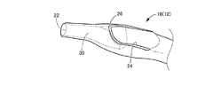
図1には、本発明のカテーテルの一実施形態であるバルーンカテーテル10の全体図が示されている。本実施形態のバルーンカテーテル10は、経皮的血管形成術の施術に際して用いられる。具体的には、例えば先行して血管へ挿入されたガイドワイヤに導かれることにより、狭窄又は閉塞した血管の病変部位に先端側が達するまで血管内に挿し入れられ、体外に位置せしめられた基端側から施術者が操作を加えることにより、先端側に設けられたバルーンで血管の病変部位を拡張して血流回復の処置を施すことができる。図1の左方、右方は夫々、バルーンカテーテル10の遠位側、近位側である。 FIG. 1 shows an overall view of a
より詳細には、バルーンカテーテル10は、所定長さのシャフト12を備えている。シャフト12において、図1の右側に位置する、手技者の近位側となる基端部には、ハブ14が接続されている。一方、図1の左側に位置する、手技者の遠位側となるシャフト12の先端近くには、径方向に拡張変形可能なバルーン16が設けられている。このようにシャフト12とハブ14とバルーン16を含むバルーンカテーテル10の基本構造は、前記特許文献1にも記載されているように公知のものである。 More specifically, the
また、シャフト12の内部には、ハブ14からバルーン16にまで至る給排ルーメンが形成されている。そして、ハブ14に接続される外部管路から、かかる給排ルーメンを通じてバルーン16に対して圧力流体が給排可能とされており、圧力流体の作用でバルーン16を拡張および収縮させることができるようになっている。 A supply/discharge lumen that extends from the
シャフト12の先端部分18は、バルーン16の先端側から更に所定長さで先端側に向けて突出している。先端部分18は、血管への挿入等に際して血管壁に当たりやすいことから特に柔らかく変形容易であることが望ましい。それ故、例えばシャフト12の本体部分よりも軟質の材料で形成された先端チップを、シャフト12の本体部分の先端へ固着して一体的に接続することで先端部分18を構成することも可能である。 The
図3に示すように、バルーン16から先端側に突出したシャフト12の先端部分18には、ガイドワイヤルーメン20が形成されている。図3の左方、右方は夫々、バルーンカテーテル10の遠位側、近位側である。ガイドワイヤルーメン20は、先端部分18の内部を長さ方向に延びている。ガイドワイヤルーメン20は、先端側ポート22と基端側ポート24との間を延びる貫通孔である。先端側ポート22はシャフト12の先端面で開口している。基端側ポート24はシャフト12の先端部分18の外周面で開口している。基端側ポート24はバルーン16よりも先端側に形成されている。 As shown in FIG. 3, a
すなわち、本実施形態のガイドワイヤルーメン20は、シャフト12においてバルーン16から突出した先端部分18にだけ形成されている。即ち、バルーンカテーテル10はガイドワイヤがシャフト12の全長に亘って挿通されないモノレールタイプのカテーテルである。 That is, the
本実施形態では、ガイドワイヤルーメン20の基端側ポート24は、シャフト12の先端部分18の外周面で開口する開口部である(図2参照)。基端側ポート24の形状は、所定の位置から先端に向かって開口幅が両側から狭まって次第に小さくなる形状である。具体的には、基端側ポート24は先細開口縁26を含む。先細開口縁26は、先端に向けて開口縁の幅が狭くなる縁である。また図3に示すように、基端側ポート24の周縁部は、基端側から先端側に向かって僅かに高くなるように傾斜している。そのため、基端側ポート24の周縁部の高さのうち、先細開口縁26の先端の高さが最も高い。高さとは、ガイドワイヤルーメン20の軸線からの最短距離に相当する。即ち、基端側ポート24の周縁部のうち、先細開口縁26の先端がガイドワイヤルーメン20の軸線から最も離れている。In the present embodiment, the
さらに本実施形態では、シャフト12の先端部分18に先端チューブ30が配設されている。先端チューブ30は、略一定の円形断面で延びるストレートな筒状部材(第1の筒状部)である。先端チューブ30はシャフト12の先端面から基端側に向かって、ガイドワイヤルーメン20の基端側ポート24近くまで延びている。先端チューブ30の内孔がガイドワイヤルーメン20を形成している。 Further, in the present embodiment, the
また、第2の筒状部としてのシャフト12の先端部分18は壁厚方向で第1の筒状部としての先端チューブ30を覆う。即ち、先端チューブ30の外周面は、シャフト12の先端部分18で略全面が覆われている。そのため、先端部分18が先端チューブ30を覆っている部分は、先端チューブ30が内周壁部であり、シャフト12の先端部分18が外周壁部である2層の周壁構造となる。このように、ガイドワイヤルーメン20の周壁部は、内周壁部である先端チューブ30と、外周壁部である先端部分18とで構成される2層の周壁構造を含む。このような積層構造の周壁部は、例えば予め準備した先端チューブ30をセットした成形キャビティに所定の樹脂材料を充填して、先端チューブ30の外周面に樹脂層を成形することにより、樹脂成形と同時に先端チューブ30が一体化された先端部分18を形成することによって得られる。 Further, the
なお、シャフト12の先端部分18を形成する材質と先端チューブ30を形成する材質とは夫々、特に限定されるものでないが、用途に応じた耐薬品性などの他、全体としてシャフト先端に要求される柔軟性や本発明で要求される引裂性を満足し得るように、軟質の合成樹脂材料が好適に採用される。具体的に例示すると、ポリウレタン樹脂やポリアミド樹脂、ポリオレフィンなどが、シャフト12の先端部分18と先端チューブ30とを形成する材料として好適に使用され得る。 The material forming the
図3から図5を参照して、ガイドワイヤルーメン20の周壁部に設けられた引裂容易部36について説明する。シャフト12の先端部分18に埋設状態で配された先端チューブ30の筒壁部には、切込状のスリット32が形成されている。特に本実施形態では、先端チューブ30に形成されたスリット32は、先端チューブ30の筒壁部を厚さ方向に貫通している第1のスリットである(図4参照)。また先端チューブ30の長さ方向では、スリット32は先端チューブ30よりも短い長さで部分的に形成される(図3参照)。これにより、先端チューブ30の長さ方向でスリット未形成部分34も残されている。スリット未形成部分34は、スリット32に沿って延びる仮想線上において、スリット32が形成されていない部分である。 With reference to FIGS. 3 to 5, the
より具体的には、図5にも示されているように、先端チューブ30の長さ方向において、先端から基端側に向けて所定長さで延びる切込状のスリット32と、基端から所定長さで延びる切込状のスリット32とが先端チューブ30に形成されている。長さ方向において、二つのスリット32の間がスリット未形成部分34である。また、先端チューブ30の基端側開口部は、スリット32の形成部分において拡開されている。この拡開された部分に入り込むように、シャフト12の基端側ポート24の先細開口縁26が位置している。 More specifically, as shown in FIG. 5, in the length direction of the
このように、ガイドワイヤルーメン20の周壁部を構成するシャフト12の先端部分18が2層構造とされており、その1層を為す先端チューブ30にスリット32が形成されている。先端チューブ30にスリット32が形成されていることで、先端部分18における引裂強度が、スリット32が位置する周上位置で部分的に小さくされている。これにより、先端部分18はスリット32に沿って長さ方向に引き裂かれ易くなっている。このように本実施形態では、シャフト12の先端部分18に、先端チューブ30のスリット32,32に沿って軸方向に直線状に延びる引裂容易部36が設けられている。 As described above, the
特に本実施形態では、スリット32は、先端部分18の周上で、ガイドワイヤルーメン20の基端側ポート24が形成されている範囲内に形成されている。即ち、スリット32の延長線上には基端側ポート24が位置している。基端側ポート24の先細開口縁26は、スリット32に向かって開口幅が狭くなる形状とされている。先細開口縁26の先端はスリット32の延長線上に位置している。 In particular, in the present embodiment, the
このようなバルーンカテーテル10を用いて血流回復処置を施すには、例えば、ガイドワイヤを経皮的に血管内に挿し入れて先端を病変部位まで導いた後、バルーンカテーテル10のガイドワイヤルーメン20に対してガイドワイヤを基端側から挿し入れて、バルーンカテーテルをガイドワイヤに沿って血管内の病変部位まで導き入れる。その後、ハブ14から給排ルーメンを通じて、バルーン16へ圧力流体を供給して拡張させることで、血管の病変部位を拡張させることができる。なお、拡張処置後には、給排ルーメン18を通じてバルーン16から圧力流体を排出させて収縮させてから、バルーンカテーテル10を血管から抜去することとなる。 To perform a blood flow restoration procedure using such a
ここにおいて、本実施形態のバルーンカテーテル10では、血管から抜去する際に、図3に仮想線(二点鎖線)で示すように万一ガイドワイヤ38がループ状等に湾曲してガイドワイヤルーメン20の基端側ポート24に引っ掛かったとしても、バルーンカテーテル10が抜去できなくなったり、基端側ポート24から横断方向に破断して先端部分18だけが血管内に留置されてしまうといった不具合が回避される。 Here, in the
すなわち、ガイドワイヤ38が湾曲して基端側ポート24に引っ掛かると、バルーンカテーテル10に外部から加えられた引抜力により、基端側ポート24の開口周縁に対してガイドワイヤ38が強く押し当てられる。この押当力は、ガイドワイヤルーメン20の周壁部に対して、基端側ポート24の開口周縁を先端側に向かって押し開いて引き裂く外力として及ぼされる。その結果、ガイドワイヤルーメン20の周壁部は、周上で引裂強度が局所的に小さくされた引裂容易部36において、かかる外力によって基端側から先端側に向かって引き裂かれる。それと同時に、ガイドワイヤ38が引裂部分を通じてガイドワイヤルーメン20から外部に外れることとなる。That is, when the
そして、ガイドワイヤルーメン20の周壁部において、基端側ポート24から徐々に引裂部分が延び、引裂部分が先端側ポート22にまで達して全長にわたると、ガイドワイヤルーメン20からガイドワイヤ38が外れる。これによりバルーンカテーテル10に対するガイドワイヤ38の引っ掛かりが完全に解消される。従って、バルーンカテーテル20の血管からの引抜きを、ガイドワイヤ38で阻害されることなく、容易に行うことができるのである。 Then, in the peripheral wall portion of the
特に本実施形態では、基端側ポート24における先端側周縁部は、引裂容易部36に向かって次第に開口幅が狭くなる先細開口縁26を含む。故に、基端側ポート24に引っ掛かったガイドワイヤ38の押当位置は、先細開口縁26に沿って先細開口縁26の先端に向けて導かれる。先細開口縁26の先端は、引裂容易部36の延長線上に位置している。このように、ガイドワイヤ38と基端側ポート24との接触部分が引裂容易部36に近接する位置へ導かれるように、基端側ポート24が形成されている。そして、基端側ポート24の周縁部に対するガイドワイヤ38の押当力が、引裂容易部36への引裂力として、一層効率的に且つ安定して作用せしめられることから、目的とするガイドワイヤ38の引っ掛かりの解除作用が安定して発揮され得る。In particular, in this embodiment, the distal end side peripheral edge portion of the proximal
また、本実施形態では、先端部分18を構成する先端チューブ30の長さ方向の中間部分にスリット未形成部分34が残されている。スリット未形成部分34の長さを変更することで、先端部分18における耐引裂強度を調節することも可能となる。 Further, in the present embodiment, the slit-
なお、このようなスリット未形成部分34が存在していても、その長さ方向両側に形成されたスリット32,32の端部間が、引裂方向で接近して対向位置していることから、基端側のスリット32の形成部分に沿って先端部分18に生ぜしめられた引裂部は、長さ方向で略直線的に延びて、略延長線上に位置する先端側のスリット32の形成部分に至って成長を続けることとなる。 Even if such a slit-
また本実施形態では、スリット32が先端チューブ30の先端開口部から基端側に向かって形成されていることから、先端チューブ30の先端開口部の変形剛性ひいてはシャフト12の先端部分18における先端開口部の変形剛性が、かかるスリット32によって一層小さく設定されている。これにより、特に血管等の管腔内面に当たりやすいシャフト12の最先端部を基端側に比べて柔らかく設定することも容易となる。なお、シャフト12の最先端部を一層柔らかく設定するために、先端チューブ30の先端開口部から基端側に向かって延びる切れ込みを、上述の引裂容易部36を構成するスリット32とは別に、周上の適切な位置に形成することも可能である。 Further, in this embodiment, since the
ところで、上述の実施形態は、ガイドワイヤルーメン20の周壁部を構成するシャフト12の先端部分18における引裂容易部36の一態様を例示するものであり、本発明では、先端部分18の引裂強度を周上の特定部位で低下せしめた各種態様を採用することが可能である。その幾つかの別態様を、以下に例示する。 By the way, the above-mentioned embodiment exemplifies one aspect of the tearing
図6は、前記実施形態で採用されていた先端チューブにおいて、スリットの形成部分と未形成部分の別態様を例示する。即ち、図6に示された態様では、前記実施形態と同様な構造とされた先端チューブ40において、壁厚方向に貫通するスリット42が、軸方向で基端側から先端側に向かって所定長さで連続して形成されている。即ち、本態様の先端チューブ40では、スリット42は軸方向において基端から中央を越えて先端近くまで延び、スリット未形成部分44はスリット42の先端から先端チューブ40の先端まで延びている。 FIG. 6 exemplifies another aspect of the portion where the slit is formed and the portion where the slit is not formed in the tip tube employed in the above-described embodiment. That is, in the embodiment shown in FIG. 6, in the
このような態様の先端チューブ40も、前記実施形態に記載の先端チューブ30に代えて用いることが可能である。この形態も、前記実施形態と同様な作用効果を得ることができる。特に、本態様の先端チューブ40では、軸方向一方の側から他方の側に向かって延びる1つのスリット42(第1のスリット)を形成すれば良いので、軸方向両側から延びる2つのスリットを備えた前記実施形態の先端チューブ30に比して製作も容易となる。 The
さらに、図7には、前記実施形態で採用されていた先端チューブに代えて採用され得る参考態様の先端チューブ46が示されている。本態様の先端チューブ46は、全長に亘って略円筒形状である。先端チューブ46には、夫々が軸方向に延びる複数のスリット48(第1のスリット)が略一定間隔で形成されている。複数のスリット48は同一線上に形成されている。複数のスリット48は夫々、所定の長さを有する。複数のスリット48のうち隣接するスリット48の間は、スリットが形成されていないスリット未形成部分49である。換言すれば、本態様では、スリット48とスリット未形成部分49とが交互に形成されて、引裂容易部はミシン目状のスリットで形成されている。Furthermore, FIG. 7 shows a
このような態様の先端チューブ46も、図7(c)に示されているように、前記実施形態に記載の先端チューブ30に代えて用いることが可能である。それによって、前記実施形態と同様に、スリット48が断続的に形成された部位においてガイドワイヤルーメン20の周壁部において長さ方向に延びる引裂容易部36を形成して、前記実施形態と同様な作用効果を発揮し得ることとなる。 The
本態様では、スリット48とスリット未形成部分49とが交互に位置するので、引裂容易部において引裂強度の弱い部分と強い部分が交互に位置する。それ故、引っ掛かったガイドワイヤ38でガイドワイヤルーメン20の周壁部が引き裂かれる際に、バルーンカテーテル10を引き抜く施術者の操作手に対して、引裂容易部を引き裂いている感触が一層伝わり易く、施術者の意識を積極的に促すことでより慎重な手技を意識させることも可能となる。なお、図7に示す参考態様では、複数のスリット48の夫々の長さは略同じである。しかし複数のスリット48の長さは互いに異なってもよい。In this aspect, since the
ところで、図1〜5に示された前記実施形態や図6〜7に示された別態様又は参考態様のように、先端チューブの長さ方向でスリット形成部分とスリット未形成部分とが形成される場合、軸方向において、スリット形成部分の合計長さはスリット未形成部分の合計長さより大きいことが望ましい。これにより、ガイドワイヤ38が引っ掛かった際にガイドワイヤルーメン20の周壁部が引裂容易部36においてよりスムーズに引き裂かれてガイドワイヤ38の離脱が実現される。By the way, as in the above-described embodiment shown in FIGS. 1 to 5 and the different modesor reference modes shown in FIGS. 6 to 7, a slit forming portion and a slit non-forming portion are formed in the length direction of the distal tube. In this case, it is desirable that the total length of the slit-formed portions is larger than the total length of the slit-unformed portions in the axial direction. As a result, when the
なお、図7(c)は、前記実施形態における図3に対応する縦断面図であり、前記実施形態と同様な構造とされた部材や部位については理解を容易とするために前記実施形態と同一の符号を付しておく。また、図7(a),(b)は、前記実施形態における図5に対応するモデル図であり、実際の縮尺に拘わらずに特徴的な構成部分を判りやすく拡大して図示したものである。更にまた、本態様の先端チューブ46の基端側は、図5(a),(b)に示された前記実施形態のように、切り開かれて拡開されたテーパ形状とされていても良い。 Note that FIG. 7C is a vertical cross-sectional view corresponding to FIG. 3 in the above-described embodiment, and members and parts having the same structure as in the above-described embodiment are different from those in the above-described embodiment in order to facilitate understanding. The same symbols are attached. Further, FIGS. 7A and 7B are model diagrams corresponding to FIG. 5 in the above-described embodiment, in which characteristic constituent parts are illustrated in an enlarged manner for easy understanding regardless of the actual scale. .. Furthermore, the proximal end side of the
また、図7に示された先端チューブ46に代えて採用され得る、更に別の参考態様の先端チューブが、それぞれ、図8(a),(b)、図9(a),(b)、図10(a),(b)に示されている。Further, tip tubes of still otherreference modes that can be adopted instead of the
図8(a),(b)に示された先端チューブ50には、周上の一箇所を壁厚方向に貫通して基端側から先端側まで軸方向に連続して延びるスリット52(第1のスリット)が形成されている。即ち、本態様の先端チューブ50は、スリット52により全長に亘って切り裂かれている。そして、このスリット52が、先端チューブ50の外層を為すシャフト12の先端部分18で覆われることにより、引裂容易部36が形成される。 The
図9(a),(b)に示された先端チューブ56には、内周面から外周面に向かって壁厚方向に未貫通の深さで形成されたスリット58が形成されている。スリット58は先端チューブ56の基端から先端まで軸方向に連続して延びる。そして、スリット58が形成された先端チューブ56の外周面が、シャフト12の先端部分18で覆われて2層構造とされることで、ガイドワイヤルーメン20の周壁部に引裂容易部36が形成される。 The
図8及び図9に示された先端チューブ50,56には、軸方向の全長に亘って略一定断面で延びるスリット52,58によって引裂容易部36が形成されている。そのため、先端チューブ50,56に設けられた引裂容易部の耐引裂強度は、全長に亘って略一定である。それ故、ガイドワイヤ38が引っ掛かった際に、ガイドワイヤルーメン20の周壁部が、引裂容易部36に沿って一層スムーズに安定して引き裂かれてガイドワイヤの引っ掛かりが解消され得る。 In the
図9に示された先端チューブ56では、引裂容易部における耐引裂強度が長さ方向において変化してもよい。例えばスリット58の壁厚方向の深さが、先端チューブ56の長さ方向で異なってもよい。 In the
さらに、図10(a),(b)に示された先端チューブ60には、図8に示された先端チューブ50と同様に壁厚方向に貫通するスリット62(第1のスリット)が軸方向全長に亘って連続して形成されている。更に、先端チューブ60の外周には、略円環状のマーカー64が装着されている。このマーカー64は、例えば白金などのX線不透過性材料で形成されており、施術中のX線による視認性を考慮して、適切な軸方向長さを有する。 Further, in the
また、かかるマーカー64は、半周を越える周方向長さを有することで、先端チューブ60の外周面に係止されるように構成されている。マーカー64には周上の一箇所で分断された開口部66が形成されている。マーカー64が先端チューブに装着された状態では、開口部66は先端チューブ60のスリット62に対して周上で同じ位置に位置している。 The
そして、マーカー64が装着された先端チューブ60の外周面がシャフト12の先端部分18で覆われることで、ガイドワイヤルーメンは2層の周壁構造に構成される。前述の如く、スリット62と開口部66とは周上で同じ位置に位置している。故に、周上においてスリット62と開口部66とが位置する部分は、他の部分に比べて長さ方向の引裂強度が小さい。これにより、ガイドワイヤが引っ掛かった際に、ガイドワイヤルーメンの周壁部において、スリット62からマーカー64の開口部66を通じて外周面に至る引裂部が壁厚方向に貫通して形成されることとなる。 The outer peripheral surface of the
それ故、ガイドワイヤルーメン20の周壁部において長さ方向に延びる引裂容易部36を形成して、バルーンカテーテル10の引き抜きに際してのガイドワイヤの引っ掛かりを速やかに解消し得るという前記実施形態と同様な作用効果を、施術中にX線で認識できるマーカー64の装着構造と併せて、シャフト12の先端部分18において実現することが可能となる。 Therefore, the same operation as in the above-described embodiment in which the tear-
なお、図10に示された態様において用いられる先端チューブ60のスリット構造は、図示のものに限定されるものでなく、例えば図5〜9に示されたスリット構造が用いられてもよい。また、容易に破断し得る材質や形状寸法を用いれば、必ずしもマーカー64の周上に開口部66が形成されていなくても良い。例えば、引っ掛かったガイドワイヤ38で及ぼされる外力で切断されるリング状のマーカー64が用いられても良い。更にまた、マーカー64の具体的形状や数も限定されない。例えば、先端チューブ60の長さ方向に沿って複数のマーカーが装着されても良い。 The slit structure of the
上述の記載から明らかなように、前記各実施形態又は参考態様では、それぞれスリット32,42,48,52,58,62が形成された先端チューブ30,40,46,50,56,60をシャフト12の先端部分18で覆うことにより、ガイドワイヤルーメン20の周壁部において壁厚方向に未貫通な切込部を含む引裂容易部36が構成されている。As is clear from the above description, in each of the above-described embodimentsor reference modes , the
さらに、ガイドワイヤルーメン20の周壁部を構成するシャフト12の先端部分18における引裂容易部36は、前述の如き先端チューブ30,40,46,50,56,60を採用することで容易に実現され得るが、そのような先端チューブを用いなくても参考態様として実現することも可能である。Further, the
具体的には、ガイドワイヤルーメン20の周壁部は先端チューブを用いないで単一の樹脂層からなる先端部分18で構成されてもよい。例えば図11〜12に示されている参考態様のように、先端部分18の外周壁から内周壁に向けて壁厚方向に所定深さで延びるスリット70が長さ方向に形成されることにより、ガイドワイヤルーメン20の周壁部において壁厚方向に未貫通な切込部を含む引裂容易部36を構成することも可能である。スリット70は、先端部分18の内周壁から外周壁に向けて壁厚方向に所定の深さで形成されてもよい。Specifically, the peripheral wall portion of the
また、このような単一層からなる先端部分18においても、壁厚方向に貫通するスリット(第2のスリット)を軸方向で部分的に形成したり、軸方向で断続的にミシン目状に形成したり、壁厚方向に貫通するスリット(第2のスリット)を軸方向の全長に亘って形成してもよい。 Further, also in the
更にまた、単一層からなる先端部分18にも、図10に示されている如きマーカー64が、ガイドワイヤルーメン20の周壁部に装着されてもよい。 Furthermore, a
以上、本発明の実施形態の別態様の幾つかについて、図面を参照しつつ詳述してきたが、本発明はこれらの具体的態様例に関する記載によって何等限定的に解釈されるものでない。 As described above, some of the other aspects of the embodiment of the present invention have been described in detail with reference to the drawings, but the present invention should not be construed as being limited to the description of these specific aspect examples.
例えば、ガイドワイヤルーメンの周壁部は3層以上の積層構造でもよい。この場合、引裂容易部は、3層以上の複数の層のうち一つ以上の層に対してスリットが形成されることで設けられてもよい。 For example, the peripheral wall portion of the guide wire lumen may have a laminated structure of three or more layers. In this case, the tearable portion may be provided by forming slits in one or more layers of the plurality of layers of three or more layers.
また、ガイドワイヤルーメンの周壁部における引裂容易部の具体的態様としては、例示の如きスリットに限定されるものでない。例えば、編組したカーボン繊維等の強化繊維を筒状にして周壁部に埋設するに際し、かかる筒状の強化繊維において周上の所定の位置で長さ方向に延びる切断部を設けることで、ガイドワイヤルーメン20の周壁部において壁厚方向に未貫通な切込部を含む引裂容易部を構成することも可能である。また引裂容易部は、スリットと切断部との組み合わせで構成されてもよい。 Further, the specific mode of the tear-prone part in the peripheral wall part of the guide wire lumen is not limited to the slit as illustrated. For example, when a reinforcing fiber such as a braided carbon fiber is formed into a tubular shape and embedded in a peripheral wall portion, a guide wire is provided by providing a cut portion extending in the longitudinal direction at a predetermined position on the circumference of the tubular reinforcing fiber. It is also possible to configure a tear-easy portion including a cut portion that does not penetrate in the wall thickness direction in the peripheral wall portion of the
或いは、ガイドワイヤルーメンの周壁部を構成する樹脂層に対して長さ方向に配向させた短繊維を配合したり、樹脂の分子構造の配列方向を長さ方向に偏向させることなどにより、周方向に比して軸方向の引裂強度を低下させて引裂容易部を構成することも可能である。 Alternatively, by blending short fibers oriented in the length direction with respect to the resin layer forming the peripheral wall of the guide wire lumen, or by deflecting the arrangement direction of the molecular structure of the resin in the length direction, It is also possible to form the easy tear portion by lowering the tear strength in the axial direction as compared with.
上述の説明からも理解されるように、本発明に係るカテーテルにおける引裂容易部は、ガイドワイヤルーメンの周壁部において長さ方向の引裂強度が周上で部分的に小さくされることによって構成されることが望ましいが、ガイドワイヤルーメン20の外周壁において周上で特定された箇所だけに引裂容易部が形成された態様に限定されるものでない。即ち、前記実施形態や複数の別態様に示されているように、ガイドワイヤルーメン20の外周壁の周上で一箇所だけに引裂容易部を設定することで、引き裂きが予定される部位を特定して設計することができるなどの利点はあるが、例えば繊維配向や分子配列の偏向などによって周上の複数箇所に引裂容易部が設定される場合でも、一般にガイドワイヤルーメンの引っ掛かりに伴う外力は一箇所に集中的に作用して一箇所の引き裂きが長さ方向に延びるし、また、最初に引き裂きが全長に至った引裂容易部を通じてガイドワイヤが離脱されることから、目的とするガイドワイヤの離脱作用は有効に発揮され得る。 As can be understood from the above description, the tear-prone part in the catheter according to the present invention is configured by partially reducing circumferential tear strength in the circumferential wall portion of the guide wire lumen in the circumferential direction. However, it is not limited to the mode in which the easy-to-tear portion is formed only on the peripheral wall of the
また、周上で複数箇所に引裂容易部が設けられてもよい。即ち、ガイドワイヤルーメンの周壁部には、複数の引裂容易部が設けられてもよい。この場合、ガイドワイヤの引っ掛かり位置が予定しない箇所に発生した場合や何等かの原因で一つの引裂容易部での引き裂きが阻害された場合でも、他の引裂容易部における引き裂き作用をフェイルセーフ的に機能させることも可能となる。その場合に、複数の引裂容易部の耐引裂強度が互いに異なるように、複数の引裂容易部を設けることで、引き裂きが発生する箇所に順位付けをしておくことも可能である。 In addition, tear-prone portions may be provided at a plurality of locations on the circumference. That is, a plurality of easy tear portions may be provided on the peripheral wall portion of the guide wire lumen. In this case, even if the guide wire is caught at an unexpected position or if the tearing at one easy tear part is obstructed for some reason, the tearing action at the other easy tear part is performed in a fail-safe manner. It is possible to make it function. In that case, by providing a plurality of tear-friendly portions so that the tear-resistant strengths of the plurality of tear-friendly portions are different from each other, it is possible to rank the places where tearing occurs.
上記実施形態では、バルーンカテーテルを例に用いて本発明の説明をした。しかしカテーテルの種類はバルーンカテーテルでなくてもよい。カテーテルは、例えば超音波画像診断カテーテル(IVUS)や吸引カテーテル、マイクロカテーテル(貫通用カテーテル)など、モノレールタイプの各種カテーテルでもよい。 In the above embodiment, the present invention has been described using the balloon catheter as an example. However, the type of catheter need not be a balloon catheter. The catheter may be various monorail type catheters such as an ultrasonic diagnostic imaging catheter (IVUS), a suction catheter, and a microcatheter (penetrating catheter).
また先端部分18は、例えばシャフト12の本体部分よりも軟質の材料で形成された先端チップを、シャフト12の本体部分の先端へ固着して一体的に接続することで構成されてもよい。この場合、ガイドワイヤルーメンは先端チップの内腔で形成されていればよい。具体的には、先端チップの先端に先端側ポートが形成されており、且つ先端チップの外周壁に基端側ポートが形成されていればよい。また先端チップの周壁構造は、一層で構成されていてもよく、また複数の層で構成されていてもよい。複数の層で先端チップの周壁構造が構成される場合、各層を形成する材料は互いに異なってもよい。 Further, the
ガイドワイヤルーメンの基端側ポートの形状は、例えば、矩形状、三角形状等の多角形状や楕円等の円形状でもよい。また基端側ポートは先細開口縁を含まなくてもよい。例えば、基端側ポートの開口縁の幅は長さ方向において一定でもよい。上記実施形態では、先細開口縁26の先端はスリット32の延長線上に位置していた。しかし先細開口縁26の先端はスリット32の延長線上に位置しなくてもよい。例えば先細開口縁26の先端はスリット32の延長線上から所定の距離、離れていてもよい。 The shape of the proximal-side port of the guide wire lumen may be, for example, a polygonal shape such as a rectangular shape or a triangular shape, or a circular shape such as an ellipse. The proximal port may not include the tapered opening edge. For example, the width of the opening edge of the proximal port may be constant in the length direction. In the above embodiment, the tip of the tapered
その他、一々列挙はしないが、本発明は、当業者の知識に基づいて種々なる変更,修正,改良等を加えた態様において実施され得るものであり、また、そのような実施態様が、本発明の趣旨を逸脱しない限り、何れも、本発明の範囲内に含まれるものであることは、言うまでもない。 In addition, although not enumerated one by one, the present invention can be carried out in a mode in which various changes, modifications, improvements, etc. are added based on the knowledge of those skilled in the art. Needless to say, all of them are included in the scope of the present invention without departing from the spirit of the above.
10:バルーンカテーテル、12:シャフト、18:先端部分、20:ガイドワイヤルーメン、22:先端側ポート、24:基端側ポート、26:先細開口縁、30,40,46,50,56,60:先端チューブ、32,42,48,52,58,62,70:スリット、34,44,49:スリット未形成部分、36:引裂容易部、38:ガイドワイヤ、64:マーカー、66:開口部10: Balloon catheter, 12: Shaft, 18: Tip part, 20: Guide wire lumen, 22: Tip side port, 24: Base end side port, 26: Tapered opening edge, 30, 40, 46, 50, 56, 60 : Tip tube, 32, 42, 48, 52, 58, 62, 70: slit, 34, 44, 49: non-slit portion, 36: tearable portion, 38: guide wire, 64: marker, 66: opening portion
Claims (5)
Translated fromJapanese壁厚方向に貫通する第1のスリットが形成された筒状部材である第1の筒状部と、該第1の筒状部を覆う第2の筒状部とを、含んで前記ガイドワイヤルーメンが形成されており、該第1の筒状部の基端側開口部が切り開かれて拡開されたテーパ形状とされていると共に、拡開された該第1の筒状部の基端側開口部に入り込むように、該第2の筒状部の外周面で開口する該ガイドワイヤルーメンの基端側ポートの先細開口縁が設けられている一方、
前記ガイドワイヤルーメンの周壁部において、前記第1のスリットが前記第2の筒状部で覆われることにより形成されている壁厚方向に未貫通な切込部を含んで、長さ方向の引裂強度が周方向に比して小さい部分である引裂容易部が設けられていることを特徴とするカテーテル。A monorail type catheter in which a guide wire lumen extending in the lengthwise direction at the tip of a shaft is formed,
The guide wire includes a first tubular portion which is a tubular member having a first slit penetrating in a wall thickness direction, and a second tubular portion which covers the first tubular portion. A lumen is formed, the base end side opening of the first tubular portion iscut open to havea tapered shape, and the proximal end of the expanded first tubular portion is formed. A tapered opening edge of a proximal end side port of the guide wire lumen which is opened at the outer peripheral surface of the second tubular portion is provided so as to enter the side opening portion,
In the circumferential wall portion of the guide wire lumen, a tear in the lengthwise direction is included, including a notch portion which is formed by the first slit being covered with the second tubular portion and which is not penetrated in the wall thickness direction. A catheter having an easy-to-tear portion, which has a lower strength than the circumferential direction.
前記ガイドワイヤルーメンの基端側ポートは、前記バルーンよりも先端側に形成されている請求項1〜4の何れか一項に記載のカテーテル。A balloon is provided on the distal end side of the shaft,
The catheter according to any one of claims 1 to 4, wherein the proximal end side port of the guide wire lumen is formed on the distal end side with respect to the balloon.
Priority Applications (4)
| Application Number | Priority Date | Filing Date | Title |
|---|---|---|---|
| JP2015069706AJP6727757B2 (en) | 2015-03-30 | 2015-03-30 | catheter |
| CN201680007473.1ACN107206205B (en) | 2015-03-30 | 2016-03-18 | Catheter tube |
| KR1020177022128AKR102051722B1 (en) | 2015-03-30 | 2016-03-18 | Catheter |
| PCT/JP2016/058621WO2016158475A1 (en) | 2015-03-30 | 2016-03-18 | Catheter |
Applications Claiming Priority (1)
| Application Number | Priority Date | Filing Date | Title |
|---|---|---|---|
| JP2015069706AJP6727757B2 (en) | 2015-03-30 | 2015-03-30 | catheter |
Publications (2)
| Publication Number | Publication Date |
|---|---|
| JP2016187527A JP2016187527A (en) | 2016-11-04 |
| JP6727757B2true JP6727757B2 (en) | 2020-07-22 |
Family
ID=57005793
Family Applications (1)
| Application Number | Title | Priority Date | Filing Date |
|---|---|---|---|
| JP2015069706AActiveJP6727757B2 (en) | 2015-03-30 | 2015-03-30 | catheter |
Country Status (4)
| Country | Link |
|---|---|
| JP (1) | JP6727757B2 (en) |
| KR (1) | KR102051722B1 (en) |
| CN (1) | CN107206205B (en) |
| WO (1) | WO2016158475A1 (en) |
Families Citing this family (1)
| Publication number | Priority date | Publication date | Assignee | Title |
|---|---|---|---|---|
| JP7369792B2 (en) | 2019-05-15 | 2023-10-26 | テレフレックス、ライフ、サイエンシーズ、アンリミテッド、カンパニー | tracheostomy dilator |
Family Cites Families (13)
| Publication number | Priority date | Publication date | Assignee | Title |
|---|---|---|---|---|
| US5389087A (en)* | 1991-09-19 | 1995-02-14 | Baxter International Inc. | Fully exchangeable over-the-wire catheter with rip seam and gated side port |
| US5383853A (en)* | 1992-11-12 | 1995-01-24 | Medtronic, Inc. | Rapid exchange catheter |
| WO1996010434A1 (en)* | 1994-10-04 | 1996-04-11 | Medtronic, Inc. | Rapid exchange catheter |
| EP0829269A1 (en)* | 1996-09-11 | 1998-03-18 | Schneider (Europe) Ag | Catheter system |
| US6007522A (en)* | 1996-09-13 | 1999-12-28 | Boston Scientific Corporation | Single operator exchange biliary catheter |
| JP2000279507A (en)* | 1999-03-30 | 2000-10-10 | Nippon Zeon Co Ltd | Balloon catheter with low temperature blow molded balloon |
| US8016752B2 (en)* | 2003-01-17 | 2011-09-13 | Gore Enterprise Holdings, Inc. | Puncturable catheter |
| US20040143286A1 (en)* | 2003-01-17 | 2004-07-22 | Johnson Eric G. | Catheter with disruptable guidewire channel |
| DE602005023731D1 (en)* | 2004-07-29 | 2010-11-04 | Wilson Cook Medical Inc | Catheter shaft with separable wall |
| WO2006015323A2 (en)* | 2004-07-29 | 2006-02-09 | Wilson-Cook Medical Inc. | Catheter with splittable wall shaft and peel tool |
| US8876704B2 (en)* | 2008-01-14 | 2014-11-04 | Boston Scientific Scimed, Inc. | Medical device |
| JP5777936B2 (en)* | 2010-07-16 | 2015-09-09 | テルモ株式会社 | Suction catheter |
| JP6039199B2 (en)* | 2012-03-12 | 2016-12-07 | 株式会社グッドマン | catheter |
- 2015
- 2015-03-30JPJP2015069706Apatent/JP6727757B2/enactiveActive
- 2016
- 2016-03-18KRKR1020177022128Apatent/KR102051722B1/enactiveActive
- 2016-03-18WOPCT/JP2016/058621patent/WO2016158475A1/ennot_activeCeased
- 2016-03-18CNCN201680007473.1Apatent/CN107206205B/enactiveActive
Also Published As
| Publication number | Publication date |
|---|---|
| CN107206205A (en) | 2017-09-26 |
| KR20170127415A (en) | 2017-11-21 |
| WO2016158475A1 (en) | 2016-10-06 |
| JP2016187527A (en) | 2016-11-04 |
| KR102051722B1 (en) | 2019-12-03 |
| CN107206205B (en) | 2020-04-03 |
Similar Documents
| Publication | Publication Date | Title |
|---|---|---|
| US10589064B2 (en) | Balloon catheter | |
| JP2019511338A (en) | Safe urinary catheter and method of manufacturing the same | |
| US20160175569A1 (en) | Device for treating vascular occlusion | |
| CN105358208B (en) | Catheter tube | |
| US10888341B2 (en) | Balloon catheter | |
| CN107530532B (en) | Device and method for performing a treatment in a tube in the body of a patient | |
| CN105963848B (en) | Balloon catheter | |
| US20200187977A1 (en) | Intravascular catheter having an expandable incising portion and medication delivery system | |
| KR20010080519A (en) | Finishing technique for a guiding catheter | |
| JP6876438B2 (en) | Balloon catheter with insertion aid for guidewire | |
| JP5896101B2 (en) | Catheter with valve | |
| JP6727757B2 (en) | catheter | |
| JP5919862B2 (en) | Balloon catheter | |
| EP3639770B1 (en) | Catheter | |
| JP6379803B2 (en) | catheter | |
| JP2016187441A (en) | catheter | |
| JP2020062319A (en) | catheter | |
| JP6523102B2 (en) | tube | |
| US12414903B2 (en) | Gastrojejunal tube apparatus and methods of use | |
| JP7467637B2 (en) | catheter | |
| JP2020062321A (en) | catheter | |
| JP6307388B2 (en) | Catheter and manufacturing method thereof | |
| CN119746251A (en) | Clamping type shunt and interventional medical instrument | |
| WO2025104713A1 (en) | Vascular dilator with stiff section | |
| JP2002315836A (en) | Guide wire introduction auxiliary tool and catheter provided with it |
Legal Events
| Date | Code | Title | Description |
|---|---|---|---|
| A621 | Written request for application examination | Free format text:JAPANESE INTERMEDIATE CODE: A621 Effective date:20171122 | |
| A131 | Notification of reasons for refusal | Free format text:JAPANESE INTERMEDIATE CODE: A131 Effective date:20180515 | |
| A521 | Request for written amendment filed | Free format text:JAPANESE INTERMEDIATE CODE: A523 Effective date:20180713 | |
| A131 | Notification of reasons for refusal | Free format text:JAPANESE INTERMEDIATE CODE: A131 Effective date:20180918 | |
| A521 | Request for written amendment filed | Free format text:JAPANESE INTERMEDIATE CODE: A523 Effective date:20181113 | |
| A02 | Decision of refusal | Free format text:JAPANESE INTERMEDIATE CODE: A02 Effective date:20190322 | |
| A521 | Request for written amendment filed | Free format text:JAPANESE INTERMEDIATE CODE: A523 Effective date:20190619 | |
| A911 | Transfer to examiner for re-examination before appeal (zenchi) | Free format text:JAPANESE INTERMEDIATE CODE: A911 Effective date:20190628 | |
| A912 | Re-examination (zenchi) completed and case transferred to appeal board | Free format text:JAPANESE INTERMEDIATE CODE: A912 Effective date:20190712 | |
| A61 | First payment of annual fees (during grant procedure) | Free format text:JAPANESE INTERMEDIATE CODE: A61 Effective date:20200701 | |
| R150 | Certificate of patent or registration of utility model | Ref document number:6727757 Country of ref document:JP Free format text:JAPANESE INTERMEDIATE CODE: R150 | |
| R250 | Receipt of annual fees | Free format text:JAPANESE INTERMEDIATE CODE: R250 | |
| R250 | Receipt of annual fees | Free format text:JAPANESE INTERMEDIATE CODE: R250 | |
| R250 | Receipt of annual fees | Free format text:JAPANESE INTERMEDIATE CODE: R250 |