JP6726967B2 - Brightness unevenness measuring device - Google Patents
Brightness unevenness measuring deviceDownload PDFInfo
- Publication number
- JP6726967B2 JP6726967B2JP2016007616AJP2016007616AJP6726967B2JP 6726967 B2JP6726967 B2JP 6726967B2JP 2016007616 AJP2016007616 AJP 2016007616AJP 2016007616 AJP2016007616 AJP 2016007616AJP 6726967 B2JP6726967 B2JP 6726967B2
- Authority
- JP
- Japan
- Prior art keywords
- measuring device
- luminance
- brightness
- measurement data
- measurement
- Prior art date
- Legal status (The legal status is an assumption and is not a legal conclusion. Google has not performed a legal analysis and makes no representation as to the accuracy of the status listed.)
- Active
Links
Images


Classifications
- G—PHYSICS
- G01—MEASURING; TESTING
- G01J—MEASUREMENT OF INTENSITY, VELOCITY, SPECTRAL CONTENT, POLARISATION, PHASE OR PULSE CHARACTERISTICS OF INFRARED, VISIBLE OR ULTRAVIOLET LIGHT; COLORIMETRY; RADIATION PYROMETRY
- G01J1/00—Photometry, e.g. photographic exposure meter
- G01J1/02—Details
- G01J1/04—Optical or mechanical part supplementary adjustable parts
- G01J1/0403—Mechanical elements; Supports for optical elements; Scanning arrangements
- G—PHYSICS
- G01—MEASURING; TESTING
- G01J—MEASUREMENT OF INTENSITY, VELOCITY, SPECTRAL CONTENT, POLARISATION, PHASE OR PULSE CHARACTERISTICS OF INFRARED, VISIBLE OR ULTRAVIOLET LIGHT; COLORIMETRY; RADIATION PYROMETRY
- G01J1/00—Photometry, e.g. photographic exposure meter
- G01J1/02—Details
- G01J1/0266—Field-of-view determination; Aiming or pointing of a photometer; Adjusting alignment; Encoding angular position; Size of the measurement area; Position tracking; Photodetection involving different fields of view for a single detector
- G—PHYSICS
- G01—MEASURING; TESTING
- G01J—MEASUREMENT OF INTENSITY, VELOCITY, SPECTRAL CONTENT, POLARISATION, PHASE OR PULSE CHARACTERISTICS OF INFRARED, VISIBLE OR ULTRAVIOLET LIGHT; COLORIMETRY; RADIATION PYROMETRY
- G01J1/00—Photometry, e.g. photographic exposure meter
- G01J1/42—Photometry, e.g. photographic exposure meter using electric radiation detectors
- G01J1/44—Electric circuits
- G—PHYSICS
- G01—MEASURING; TESTING
- G01J—MEASUREMENT OF INTENSITY, VELOCITY, SPECTRAL CONTENT, POLARISATION, PHASE OR PULSE CHARACTERISTICS OF INFRARED, VISIBLE OR ULTRAVIOLET LIGHT; COLORIMETRY; RADIATION PYROMETRY
- G01J1/00—Photometry, e.g. photographic exposure meter
- G01J1/42—Photometry, e.g. photographic exposure meter using electric radiation detectors
- G01J2001/4247—Photometry, e.g. photographic exposure meter using electric radiation detectors for testing lamps or other light sources
Landscapes
- Physics & Mathematics (AREA)
- General Physics & Mathematics (AREA)
- Spectroscopy & Molecular Physics (AREA)
- Testing Of Optical Devices Or Fibers (AREA)
- Studio Devices (AREA)
Description
Translated fromJapaneseこの発明は、表示装置における表示領域内の輝度分布を測定する輝度ムラ測定装置に関する。 The present invention relates to a brightness unevenness measuring device that measures a brightness distribution in a display area of a display device.
液晶表示装置等の表示装置は、ノートPC、テレビ又は携帯電話等、多くの技術分野で応用されている。そして、その表示品位の向上の面から、表示面内の明るさ(輝度)又は色(色度)の分布(ムラ)が問題となっており、輝度ムラ又は色度ムラを高精細に測定する装置が求められている。 A display device such as a liquid crystal display device is applied in many technical fields such as a notebook PC, a television or a mobile phone. From the viewpoint of improving the display quality, the distribution (unevenness) of brightness (luminance) or color (chromaticity) on the display surface is a problem, and unevenness in luminance or chromaticity is measured with high precision. A device is needed.
輝度ムラ又は色度ムラの定量評価を行うための測定装置として、計測器メーカーにより測定装置が開発されている。例えば2次元色彩輝度計(CA−2000、コニカミノルタセンシング株式会社製、特許文献1)は、面内の輝度分布を写真撮影のように一括で行うことができる。この測定装置の測定結果の解像度は980×980ドットであり、例えば一回の測定で、980×980個の輝度データを一括で得ることができる。 A measuring device has been developed by a measuring instrument manufacturer as a measuring device for quantitatively evaluating luminance unevenness or chromaticity unevenness. For example, a two-dimensional color luminance meter (CA-2000, manufactured by Konica Minolta Sensing Co., Ltd., Patent Document 1) can collectively perform in-plane luminance distribution like a photograph. The resolution of the measurement result of this measuring device is 980×980 dots, and for example, it is possible to collectively obtain 980×980 luminance data by one measurement.
近年、ハイビジョンテレビの登場に代表されるように、表示装置の高精細化が進んでおり、その表示領域の画素数は増える傾向にある。しかしながら、特許文献1の測定装置では、その解像度が撮像素子の解像度に制限されるため、撮像素子の解像度以上のサンプルを測定する場合には、相対的に測定結果が粗くなるという問題がある。 In recent years, as typified by the advent of high-definition televisions, high definition display devices have been developed, and the number of pixels in the display area tends to increase. However, in the measuring device of Patent Document 1, the resolution is limited to the resolution of the image sensor, and thus there is a problem that the measurement result becomes relatively rough when measuring a sample having a resolution higher than that of the image sensor.
本発明は上述の問題に鑑み、高解像度のサンプルを高精細に測定することのできる輝度ムラ測定装置の提供を目的とする。 The present invention has been made in view of the above problems, and an object thereof is to provide a luminance unevenness measuring device capable of measuring a high-resolution sample with high precision.
本発明の輝度ムラ測定装置は、測定サンプルの表示面の面内輝度を測定する輝度測定装置と、輝度測定装置を搭載して固定し、輝度測定装置のノーダルポイントを中心に輝度測定装置を回転させる回転機構を有する治具と、少なくとも表示面内の第1表示領域の輝度測定装置による第1測定データと、第1表示領域と隣接する表示面内の第2表示領域の輝度測定装置による第2測定データとを接合する測定データ接合部と、を備え、第1、第2測定データは、輝度測定装置が治具に固定された状態で回転機構により測定サンプルに正対した状態から互いに異なる角度だけ回転した姿勢で測定して得られたデータであり、データ接合部は、第1測定データと第2測定データの境界部分における同値の部分を重ねるように、第1測定データと第2測定データを接合することで、測定サンプルの表示面全体の面内輝度の測定データを得る。The brightness unevenness measuring device of the present invention is a brightness measuring device for measuring the in-plane brightness of the display surface of a measurement sample, and the brightness measuring device is mounted andfixed, and the brightness measuring device is centered around the nodal point of the brightness measuring device. By a jig having a rotating mechanism for rotating, first measurement data byat least the brightness measuring device in the first display area in the display surface, and brightness measuring device in the second display area in the display surface adjacent to the first display area. And a measurement data joining portion for joining the second measurement data, whereinthe first and second measurement data aremutually separated from a state in which the luminance measurement device isfixed to the jig and the measurement sample is directly faced by the rotation mechanism.Ri Ah with data obtained by measuringin a posturerotatedby differentangles, the data junction, to overlap the equivalent portion at the boundary portion of the first measurement data and the second measurement data, and the first measurement data a by joining the second measurement data, Ruobtain measurement data plane luminance of the entire display surface of the measurement sample.
本発明の輝度ムラ測定装置は、測定サンプルの表示面の面内輝度を測定する輝度測定装置と、輝度測定装置を搭載して固定し、輝度測定装置のノーダルポイントを中心に輝度測定装置を回転させる回転機構を有する治具と、少なくとも表示面内の第1表示領域の輝度測定装置による第1測定データと、第1表示領域と隣接する表示面内の第2表示領域の輝度測定装置による第2測定データとを接合する測定データ接合部と、を備え、第1、第2測定データは、輝度測定装置が治具に固定された状態で回転機構により測定サンプルに正対した状態から互いに異なる角度だけ回転した姿勢で測定して得られたデータであり、データ接合部は、第1測定データと第2測定データの境界部分における同値の部分を重ねるように、第1測定データと第2測定データを接合することで、測定サンプルの表示面全体の面内輝度の測定データを得る。輝度測定装置はノーダルポイントを中心に回転して第1表示領域と第2表示領域とを測定するため、得られた第1測定データと第2測定データとは連続性を持つ。従って、これらを合成することにより、高解像度の測定サンプルの輝度分布を高精細に測定することができる。
The brightness unevenness measuring device of the present invention is a brightness measuring device for measuring the in-plane brightness of the display surface of a measurement sample, and the brightness measuring device is mounted andfixed, and the brightness measuring device is centered around the nodal point of the brightness measuring device. By a jig having a rotating mechanism for rotating, first measurement data byat least the brightness measuring device in the first display area in the display surface, and brightness measuring device in the second display area in the display surface adjacent to the first display area. And a measurement data joining portion for joining the second measurement data, whereinthe first and second measurement data aremutually separated from a state in which the luminance measurement device isfixed to the jig and the measurement sample is directly faced by the rotation mechanism.Ri Ah with data obtained by measuringin a posturerotatedby differentangles, the data junction, to overlap the equivalent portion at the boundary portion of the first measurement data and the second measurement data, and the first measurement data a by joining the second measurement data, Ruobtain measurement data plane luminance of the entire display surface of the measurement sample. Since the luminance measuring device rotates around the nodal point to measure the first display area and the second display area, the obtained first measurement data and second measurement data have continuity. Therefore, by combining these, it is possible to measure the luminance distribution of a high-resolution measurement sample with high precision.
<A.前提技術>
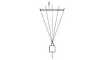
図1は、第1の前提技術に係る輝度ムラ測定の概要を示す図である。測定サンプル2に輝度測定装置1を正対して配置し、一度に測定サンプル2の表示面内の輝度分布を測定する。輝度測定装置1は、例えば面内輝度測定装置として公知の2次元色彩輝度計(コニカミノルタセンシング社製、CA−2000)であり、測定サンプル2は、例えば対角寸法が7インチのWVGAの液晶表示装置である。<A. Base technology>
FIG. 1 is a diagram showing an outline of luminance unevenness measurement according to the first prerequisite technique. The luminance measuring device 1 is arranged to face the
このように一度に表示面内の輝度分布を測定する方法では、輝度測定装置1の測定素子の解像度が測定サンプル2の解像度よりも低い場合に、相対的に測定結果の解像度が粗くなってしまうという問題があった。 In this way, in the method of measuring the luminance distribution on the display surface at once, when the resolution of the measuring element of the luminance measuring device 1 is lower than the resolution of the
図2は、第2の前提技術に係る輝度ムラ測定の概要を示す図である。この方法は、測定サンプル2の表示面を複数の領域に分割し、分割領域ごとに輝度分布を測定し、その後、夫々の測定データを合成するというものである。図2では、測定サンプル2の表示領域の左半分を第1表示領域2a、右半分を第2表示領域2bとして分割している。 FIG. 2 is a diagram showing an outline of luminance unevenness measurement according to the second base technology. In this method, the display surface of the
図2に示す分割測定では、表示面内の輝度分布の全体像を分かりやすくするため、各分割領域の測定データを合成する。しかし、輝度測定装置1のセッティングにより第1表示領域2a,第2表示領域2b間で観測方向にズレがあるため、第1表示領域2aの測定データと第2表示領域2bの測定データには連続性が無い。従って、第1表示領域2a、第2表示領域2bの中央部では隣接領域と測定データの比較を行うことが出来るが、第1表示領域2a、第2表示領域2bの境界部では隣接領域と測定データの比較を行うことが出来ない、という問題がある。 In the divided measurement shown in FIG. 2, in order to make the whole image of the luminance distribution on the display surface easy to understand, the measurement data of each divided region are combined. However, due to the setting of the luminance measuring device 1, there is a deviation in the observation direction between the
そこで本発明は、既存の輝度ムラ測定装置を用いて高解像度の測定サンプルの高精細な測定データを得るため、以下のような工夫を施した。 Therefore, the present invention has been devised as follows in order to obtain high-definition measurement data of a high-resolution measurement sample using an existing luminance unevenness measuring device.
<B.実施の形態1>
<B−1.構成>
図3は、本発明の実施の形態1に係る輝度ムラ測定装置101の構成と、測定サンプル2との位置関係を説明する図である。なお、本明細書で説明する図3以降の図において、前提技術の項で説明した図1,2と同様の構成要素には同様の参照符号を付している。<B. Embodiment 1>
<B-1. Composition>
FIG. 3 is a diagram for explaining the configuration of the luminance
輝度ムラ測定装置101は、輝度測定装置1、輝度測定装置1を搭載する治具4、治具4を設置する三脚3、及び演算部6を備えて構成される。 The brightness
輝度測定装置1には、例えば面内輝度測定装置として公知の2次元色彩輝度計(コニカミノルタセンシング社製、CA−2000)を用いる。輝度測定装置1は、対物レンズ、CCDセンサ等(図示せず)により構成され、測定サンプル2の面内輝度又は面内色度を計測する。なお、輝度測定装置1は望遠レンズを装着しており、その測定範囲を角度で表現した場合の画角は約±4°である。 As the brightness measuring device 1, for example, a two-dimensional color brightness meter (CA-2000 manufactured by Konica Minolta Sensing Co., Ltd.) known as an in-plane brightness measuring device is used. The luminance measuring device 1 is composed of an objective lens, a CCD sensor and the like (not shown), and measures the in-plane luminance or the in-plane chromaticity of the
測定サンプル2には、例えば対角寸法が7インチのWVGAの液晶表示装置を用いる。測定サンプル2は、表示面の法線方向が水平、かつ表示領域の長辺が水平となるように設置される。 As the
輝度ムラ測定装置101は、測定サンプル2と正対し、測定サンプル2の表示面の中央部を法線方向から観察するように設置される。 The brightness
治具4は、回転軸5を中心に矢印5Dで示す向きに回転する回転機構を有している。従って、輝度測定装置1は治具4に固定された状態で回転軸5を中心に回転動作を行うことが出来る。 The
また、治具4は矢印41Dの方向に輝度測定装置1をスライドさせるスライド機構41を有している。従って、輝度測定装置1は治具4に固定された状態で矢印41Dの方向にスライド動作を行うことが出来る。矢印41Dの方向は、輝度ムラ測定装置101が測定サンプル2に正対して配置された状態で、測定サンプル2の表示面の法線に対して平行な方向となるようにする。従って、輝度測定装置1は、スライド機構41により測定サンプル2の表示面の法線に対して平行な方向にスライドすることができる。 Further, the
演算部6は、データ特定部61、台形歪補正部62及びデータ接合部63を備えている。データ特定部61は、輝度測定装置1の測定データから、各分割領域の測定データを特定する。台形歪補正部62は、輝度測定装置1の測定データの台形歪を補正する。データ接合部63は、後述する測定サンプル2の分割表示領域の測定データを接合して、測定サンプル2の表示面全体の測定データを作成する。 The
図4は、演算部6のハードウェア構成を示す図である。演算部6は、輝度ムラ測定装置1から測定データを取得する入力インタフェース(I/F)71、プロセッサ72、メモリ73により実現される。データ特定部61、台形歪補正部62及びデータ接合部63は、CPU(Central Processing Unit)等のプロセッサ72が、RAM(Random Access Memory)等のメモリ73に格納されたソフトウェアプログラムを実行することにより、プロセッサ72の機能として実現される。但し、これらは例えば複数のプロセッサ72が連携して実現されても良い。 FIG. 4 is a diagram showing a hardware configuration of the
<B−2.測定手順>
輝度ムラ測定装置101を用いた測定サンプル2の面内輝度の測定手順を、図5のフローチャートに沿って説明する。<B-2. Measurement procedure>
A procedure for measuring the in-plane luminance of the
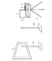
まず、輝度測定装置1のノーダルポイントが治具4の回転軸5と一致するように位置調整を行う(ステップS1)。ノーダルポイントとは、輝度測定装置1を構成する対物レンズの焦点中心のことである。 First, the position is adjusted so that the nodal point of the brightness measuring device 1 coincides with the
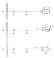
図6は、輝度測定装置1のノーダルポイントの位置合わせ方法を説明する斜視図、図7は、輝度測定装置1のノーダルポイントの位置合わせ方法を説明する上面図である。ノーダルポイントの位置合わせをするための補助部品として、棒81,82を2本用意する。2本の棒81,82は、輝度測定装置1の光軸上で鉛直に設置される。このとき図7(a)に示すように、輝度測定装置1から2本の棒81,82が重なって観察される。なお、図7ではノーダルポイントをPで示している。 FIG. 6 is a perspective view illustrating a method of aligning the nodal points of the luminance measuring apparatus 1, and FIG. 7 is a top view illustrating a method of aligning the nodal points of the luminance measuring apparatus 1. Two
今、回転軸5を中心に輝度測定装置1をθ、例えば約3°回転させる(図7(b))。ノーダルポイントPと回転軸5が一致していないため、この状態では輝度測定装置1から2本の棒81,82は重なって観察されない。 Now, the brightness measuring device 1 is rotated about the
そこで、スライド機構41により輝度測定装置1を治具4上で前後に動かし、輝度測定装置1から2本の棒81,82が重なって観察されるような輝度測定装置1の位置を探す。この位置調整により2本の棒81,82が重なって観察されるようになれば、そのとき、輝度測定装置1のノーダルポイントPは回転軸5と一致している(図7(c))。なお、スライド機構41は、輝度測定装置1のノーダルポイントPを治具4の回転軸5に位置合わせすることを目的としているため、輝度測定装置1を治具4の回転軸5に対して移動する機構が治具4に備わっていれば良く、例えば段階的に位置を調整する機構等、スライド機構41以外の移動機構でも良い。輝度測定装置1のノーダルポイントPを回転軸5に一致させることにより、後工程で測定する各表示領域2a,2bの測定データ間に視差の影響がなくなり、これらのデータが連続性を有するため、これらのデータを接合して表示領域全体の測定データを得ることが可能になる。 Then, the brightness measuring device 1 is moved back and forth on the
以上が図5のステップS1である。次に、ノーダルポイントPの位置合わせ後、測定サンプル2の輝度測定を行う。測定サンプル2の表示領域を複数の領域に分割し、分割領域ごとに輝度ムラ測定を行う。なお、ここでは測定サンプル2の表示領域を左半分の第1表示領域2aと右半分の第2表示領域2bという2つの領域に分割する例を説明するが、分割の仕方はこれに限らない。例えば、3分割又は4分割にしても良いし、上下方向に表示領域を分割しても良い。分割数を増やすことによって、より高解像度な測定サンプル2にも対応することが出来る。また、本測定では測定サンプル2の白表示時の輝度ムラ測定を行うが、白表示に限らず、中間調表示又は黒表示時の輝度ムラ測定を行っても良い。 The above is step S1 of FIG. Next, after aligning the nodal point P, the luminance of the
図8は、輝度測定装置1により測定サンプル2の輝度を測定する方法を説明するための図である。まず、治具4の回転機構により輝度測定装置1を測定サンプル2に正対した状態から3°回転させ、第1表示領域2a側の輝度分布を測定する(ステップS2)。図8(a)は、この状態の測定サンプル2と輝度測定装置1との位置関係を示している。上記で「第1表示領域2a側の輝度分布」と述べているのは、本ステップでは第1表示領域2aだけでなく、第2表示領域2bの第1表示領域2a側の一部領域の輝度分布も測定されるからである。 FIG. 8 is a diagram for explaining a method of measuring the luminance of the
次に、データ特定部61により、ステップS2で取得した測定データの中から第1表示領域2aの測定データ(第1測定データ)を特定する(ステップS3)。この特定方法については具体例を後述する。 Next, the
図8(a)に示すように、第1表示領域2a側の輝度測定において輝度測定装置1は第1表示領域2aに正対せず斜め方向から測定するため、図9に示すように第1表示領域2aの測定データ(第1測定データ)は、台形形状の領域の測定データとなる。すなわち、測定データに台形歪が発生している。そこで、台形歪補正部62によりこの台形歪を補正する演算を行う(ステップS4)。この補正演算については具体例を後述する。 As shown in FIG. 8A, in the luminance measurement on the side of the
次に、治具4の回転機構により輝度測定装置1を測定サンプル2に正対した状態から−3°回転させ、第2表示領域2b側の輝度分布を測定する(ステップS5)。図8(b)は、この状態の測定サンプル2と輝度測定装置1との位置関係を示している。上記で「第2表示領域2b側の輝度分布」と述べているのは、本ステップでは第2表示領域2bだけでなく、第1表示領域2aの第2表示領域2b側の一部領域の輝度分布も測定されるからである。 Next, the rotation mechanism of the
次に、データ特定部61により、ステップS5で取得した測定データの中から第2表示領域2bの測定データを特定する(ステップS6)。この特定方法はステップS3と同様であり、具体例を後述する。 Next, the
図8(b)に示すように、第2表示領域2b側の輝度測定において輝度測定装置1は第2表示領域2bに正対せず斜め方向から測定するため、図9に示す第1表示領域2aの測定結果と同様、第2表示領域2bの測定結果も台形形状となる。具体的には、図9に示す第1表示領域2aの測定結果を左右対称にした台形形状となる。従って、第2表示領域2bの測定結果についても台形歪補正部62により補正する演算を行う(ステップS7)。この補正演算はステップS4と同様であり、具体例を後述する。 As shown in FIG. 8B, in the luminance measurement on the side of the
最後に、ステップS4で補正した第1表示領域2aの測定データとステップS7で補正した第2表示領域2bの測定データとをデータ接合部63により接合し、測定サンプル2の表示面全体の輝度分布の測定データを得る(ステップS8)。第1表示領域2aと第2表示領域2bの境界部分については、第1表示領域2aの測定データにも第2表示領域2bの測定データにも測定値が存在する。両測定データは、輝度測定装置1がノーダルポイントPを中心に回転した、その異なる回転姿勢で測定したものであるため、両測定において測定点と輝度測定装置1の方向は同一となる。従って、測定サンプル2の視野角特性の影響もないので、第1表示領域2aと第2表示領域2bの境界部分について両測定データでは同値が得られる。 Finally, the measurement data of the
そこで、第1表示領域2aと第2表示領域2bの境界部分を基準に、この同値の部分を重ねるように両測定データを接合することで、測定サンプル2の表示面全体の輝度分布の測定データが得られる(図8(c))。 Therefore, the measurement data of the luminance distribution of the entire display surface of the
すなわち、実施の形態1に係る輝度ムラ測定装置101は、測定サンプル2の表示面の面内輝度を測定する輝度測定装置1と、輝度測定装置1を搭載し、輝度測定装置1のノーダルポイントPを中心に輝度測定装置1を回転させる回転機構を有する治具4と、表示面内の第1表示領域2aの輝度測定装置1による第1測定データと、第1表示領域2aと隣接する表示面内の第2表示領域2bの輝度測定装置1による第2測定データとを接合するデータ接合部63と、を備える。第1、第2測定データは、輝度測定装置1が回転機構による互いに異なる回転姿勢で測定して得られたデータであるため、視差の無い連続性のあるデータである。そのため、これらを接合することで、測定サンプル2の表示面全体の輝度ムラの測定データを得ることが出来る。従って、測定サンプル2の解像度が輝度測定装置1の測定素子の解像度より高い場合でも、高精度に輝度の測定を行うことが出来る。 That is, the luminance
<B−3.測定データの特定>
図5のステップS3,6における測定データの特定方法について説明する。第1表示領域2a側の測定データから第1表示領域2aの測定データを特定し、第2表示領域2b側の測定データから第2表示領域2bの測定データを特定するには、第1表示領域2aと第2表示領域2bの境界線を把握する必要がある。<B-3. Identification of measurement data>
A method of specifying measurement data in steps S3 and S6 of FIG. 5 will be described. To specify the measurement data of the
図10は、この境界線を見つけるため測定サンプル2の表示面に表示する画像を示している。この画像は、表示領域の中央部、すなわち第1表示領域2aと第2表示領域2bの境界に白い1本線を示している。 FIG. 10 shows an image displayed on the display surface of the
輝度測定装置1が第1表示領域2a側の輝度を測定した後、そのままの回転姿勢で、続いて測定サンプル2に表示された図10に示す画像の輝度を測定する。これにより、980×980ドット分の輝度データの中に、中央部の線に相当する高い輝度を示す一直線状のデータが得られる。これが、測定サンプル2の中央部であるため、このデータを用いて第1表示領域2aの輝度データを特定する。 After the brightness measuring device 1 measures the brightness on the side of the
同様に、輝度測定装置1が第2表示領域2b側の輝度を測定した後、そのままの回転姿勢で、続いて測定サンプル2に表示された図10に示す画像の輝度を測定し、同様にして第2表示領域2bの輝度データを特定する。 Similarly, after the brightness measuring device 1 measures the brightness on the
但し、表示領域の境界線を識別する方法は上記の方法に限らない。例えば、第1表示領域2a、第2表示領域2bの輝度を測定する際の輝度測定装置1の回転角度と、輝度測定装置1と測定サンプル2との距離、輝度測定装置1のレンズ性能等から、表示領域の境界線を計算で算出しても良い。 However, the method of identifying the boundary line of the display area is not limited to the above method. For example, from the rotation angle of the brightness measuring device 1 when measuring the brightness of the
<B−4.測定データの補正>
次に、第2表示領域2bの測定データの台形歪補正について説明する。第1表示領域2aの測定データの台形歪補正は第2表示領域2bの測定データの台形歪補正と同様であるため、ここでは第2表示領域2bの測定データの台形歪補正のみ説明する。<B-4. Correction of measurement data>
Next, the trapezoidal distortion correction of the measurement data in the
図11は、第2表示領域2b(ここでは面Sと示す)の輝度測定を行う際の、第2表示領域2bと輝度測定装置1との位置関係を示している。輝度測定装置1は、測定サンプル2の第2表示領域2bに正対する方向から角度θだけ傾けて第2表示領域2bの輝度を測定する。測定データは、撮像範囲の輝度分布が輝度測定装置1に正対するxy平面に投影されて記録される。x軸、y軸の原点を輝度測定装置1と対向する位置に取り、xy平面に垂直な向きにz軸をとると、輝度測定装置1はz軸上の点Z(0,0,L)に位置する。そして、ある測定点A1(p,q,0)の輝度値は、測定サンプル2上の点A2の輝度値である。ここで、A2の座標を求める。 FIG. 11 shows the positional relationship between the
実際の測定サンプル2は、次の数式で表現される平面S上に存在する。 The

よって、A2は、平面Sと直線AZの交点として演算可能であり、A2(x2、y2、z2)の座標は次のようになる。 Therefore, A2 can be calculated as the intersection of the plane S and the straight line AZ, and the coordinates of A2 (x2, y2, z2) are as follows.
任意のA2は、Y軸を中心に−θ回転させることで、XY平面上に移動させることが出来るため、これをA3(x3、y3、z3)とすると、下記のようになる。 The arbitrary A2 can be moved on the XY plane by rotating -θ about the Y axis. Therefore, when this is A3 (x3, y3, z3), the following is obtained.
測定データの任意の点A1の輝度値は、実際には、測定サンプル2上の点A2の輝度値であり、これをxy平面上の点A3の輝度値と置き換えることで、台形歪を補正することが出来る。 The brightness value of the arbitrary point A1 of the measurement data is actually the brightness value of the point A2 on the
こうして計算された各点の測定データに基づき、必要な個所の値を例えば線形補間演算することで、任意の点の測定データを得ることが出来る。これにより、補正演算が完了する。なお、以上に示した補正演算は例示であり、他の補正方法を用いても良い。 Based on the measured data of each point calculated in this way, the value of a required location is subjected to, for example, a linear interpolation calculation to obtain the measured data of an arbitrary point. This completes the correction calculation. The correction calculation shown above is an example, and other correction methods may be used.
このように、輝度ムラ測定装置101は輝度測定装置1が測定領域に対して正対しないことにより生じる測定データの台形歪を補正する台形歪補正部62を備えるので、台形歪を補正した正確な測定データを得ることが出来る。 As described above, since the brightness
<C.実施の形態2>
図12は、実施の形態2に係る輝度ムラ測定装置102の構成を示している。なお、輝度ムラ測定装置102は実施の形態1と同様、演算部6を備えているが、ここでは図示を省略している。輝度ムラ測定装置102は、三脚3、三脚3に固定する治具4B、治具4Bに搭載する輝度測定装置1及び演算部6(図示省略)を備えている。<
FIG. 12 shows the configuration of the luminance
治具4Bには、輝度測定装置1がネジ7により取り付けられる。そして、輝度測定装置1はネジ7を回転軸として回転可能である。言い換えれば、治具4Bは、ネジ7を回転軸として輝度測定装置1を回転させる回転機構を有している。ネジ7の回転軸が輝度測定装置1のノーダルポイントPと一致するように予め輝度測定装置1に対するネジ7の取り付け位置を設定しておけば、図5のステップS1に示したノーダルポイントPの位置合わせ工程が不要である。従って、当該位置合わせをするためのスライド機構41も治具4Bには不要である。 The brightness measuring device 1 is attached to the
すなわち、輝度ムラ測定装置102において、輝度測定装置1と回転機構の回転軸との距離は固定であり、その距離を調整することは出来ないが、予め回転機構の回転軸を輝度測定装置1のノーダルポイントに重ねて設定しておくことにより、ノーダルポイントの位置合わせを省略することが出来る。 That is, in the brightness
また、上記の回転軸を、輝度測定装置1を治具4Bに取り付けるためのネジ7の回転軸とする、言いかえれば、ネジ7の回転軸を輝度測定装置1のノーダルポイントに重ねることにより、治具4Bに別途の回転機構を設ける必要がなく、治具4Bの構成を簡略化できる。 In addition, the above rotary shaft is used as the rotary shaft of the
<D.変形例>
以上の説明では、輝度測定装置1は、それ自体が回転機構を有さず、治具4Bに取り付けられることで治具4Bと一体となって回転するものとして説明した。しかし、輝度測定装置1自体が回転機構を有していても良い。当該回転機構は、輝度測定装置1のノーダルポイントに重ねて回転軸が設定される。すなわち、輝度測定装置1は、輝度測定装置1のノーダルポイント中心に輝度測定装置1を回転させる回転機構を有している。この場合、治具4Bは不要となる。<D. Modification>
In the above description, the luminance measuring device 1 does not have a rotating mechanism itself, but is attached to the
以上の説明では、データ特定部61、台形歪補正部62及びデータ接合部63は、図4のプロセッサ72がメモリ73に格納されたソフトウェアプログラムに従って動作することにより実現された。しかしこれに代えて、データ特定部61、台形歪補正部62及びデータ接合部63は、当該動作をハードウェアの電気回路で実現する信号処理回路により実現されても良い。ソフトウェアのデータ特定部61、台形歪補正部62及びデータ接合部63と、ハードウェアのデータ特定部61、台形歪補正部62及びデータ接合部63とを合わせた概念として、「部」という語に代えて「処理回路」という語を用いることも出来る。 In the above description, the
なお、本発明は、その発明の範囲内において、各実施の形態を自由に組み合わせたり、各実施の形態を適宜、変形、省略することが可能である。 It should be noted that, in the present invention, the respective embodiments can be freely combined, or the respective embodiments can be appropriately modified or omitted within the scope of the invention.
1 輝度測定装置、2 測定サンプル、2a 第1表示領域、2b 第2表示領域、3 三脚、4,4B 治具、5 回転軸、6 演算部、7 ネジ、41 スライド機構、61 データ特定部、62 台形歪補正部、63 データ接合部、71 入力インタフェース、72 プロセッサ、73 メモリ、81,82 棒、101,102 輝度ムラ測定装置。 1 luminance measuring device, 2 measurement sample, 2a 1st display area, 2b 2nd display area, 3 tripod, 4, 4B jig, 5 rotation axis, 6 arithmetic section, 7 screw, 41 slide mechanism, 61 data specifying section, 62 trapezoidal distortion correction unit, 63 data joining unit, 71 input interface, 72 processor, 73 memory, 81, 82 bar, 101, 102 luminance unevenness measuring device.
Claims (6)
Translated fromJapanese前記輝度測定装置を搭載して固定し、前記輝度測定装置のノーダルポイントを中心に前記輝度測定装置を回転させる回転機構を有する治具と、
少なくとも前記表示面内の第1表示領域の前記輝度測定装置による第1測定データと、前記第1表示領域と隣接する前記表示面内の第2表示領域の前記輝度測定装置による第2測定データとを接合するデータ接合部と、を備え、
前記第1、第2測定データは、前記輝度測定装置が前記治具に固定された状態で前記回転機構により前記測定サンプルに正対した状態から互いに異なる角度だけ回転した姿勢で測定して得られたデータであり、
前記データ接合部は、前記第1測定データと前記第2測定データの境界部分における同値の部分を重ねるように、前記第1測定データと前記第2測定データを接合することで、前記測定サンプルの前記表示面全体の面内輝度の測定データを得る、
輝度ムラ測定装置。A luminance measuring device for measuring the in-plane luminance of the display surface of the measurement sample,
A jig having a rotation mechanism for mounting andfixing the brightness measuring device, and rotating the brightness measuring device around a nodal point of the brightness measuring device,
A first measurement data obtained by the luminance measurement apparatus of the first display area ofat least the display surface, and the second measurement data obtained by the luminance measurement apparatus of the second display region in the display surface adjacent to the first display region A data joining part for joining
It said first, second measurement data, measured in a posture in which the luminance measuring deviceis rotatedby differentanglesfrom directly facing state byRi the measurement sample to the rotating mechanismin a fixed state to the jigRi Oh with the resulting data,
The data joining unit joins the first measurement data and the second measurement data so that the portions of the same value in the boundary portion between the first measurement data and the second measurement data overlap each other, thereby Obtaining measurement data of in-plane luminance of the entire display surface,
Brightness unevenness measuring device.
請求項1に記載の輝度ムラ測定装置。The jig has a moving mechanism that moves the brightness measuring device so that a nodal point of the brightness measuring device coincides with a rotation axis of the rotating mechanism.
The brightness unevenness measuring device according to claim 1.
前記回転機構の回転軸は前記輝度測定装置のノーダルポイントに重なる、
請求項1に記載の輝度ムラ測定装置。The distance between the brightness measuring device and the rotating shaft of the rotating mechanism is fixed,
The rotation axis of the rotation mechanism overlaps the nodal point of the luminance measuring device,
The brightness unevenness measuring device according to claim 1.
前記第2測定データは、前記輝度測定装置が前記測定サンプルに正対した状態から前記第1軸の左回りに前記第1角度回転した姿勢で測定して得られたデータである、 The second measurement data is data obtained by measuring the luminance measuring device in a posture in which it is rotated counterclockwise to the first axis by the first angle from a state of directly facing the measurement sample,
請求項1から請求項3のいずれか1項に記載の輝度ムラ測定装置。The brightness unevenness measuring device according to claim 1.
前記表示面内の第1表示領域の前記輝度測定装置による第1測定データと、前記第1表示領域と隣接する前記表示面内の第2表示領域の前記輝度測定装置による第2測定データとを接合するデータ接合部と、を備え、
前記輝度測定装置は、前記輝度測定装置のノーダルポイントを中心に前記輝度測定装置を回転させる回転機構を有し、
前記第1、第2測定データは、前記輝度測定装置が前記回転機構により前記測定サンプルに正対した状態から互いに異なる角度だけ回転した姿勢で測定して得られたデータであり、
前記データ接合部は、前記第1測定データと前記第2測定データの境界部分における同値の部分を重ねるように、前記第1測定データと前記第2測定データを接合することで、前記測定サンプルの前記表示面全体の面内輝度の測定データを得る、
輝度ムラ測定装置。A luminance measuring device for measuring the in-plane luminance of the display surface of the measurement sample,
The first measurement data of the brightness measuring device in the first display area in the display surface, and the second measurement data of the brightness measuring device in the second display area in the display surface adjacent to the first display area. A data joining portion to be joined,
The brightness measuring device has a rotation mechanism for rotating the brightness measuring device around a nodal point of the brightness measuring device,
Said first, second measurement data,Ri Ah with data obtained by measuringin a posturerotatedby differentangles from each otherfrom a state in which the luminance measuring deviceis directly facing the byRi the measurement sample to the rotating mechanism,
The data joining unit joins the first measurement data and the second measurement data so that the portions of the same value in the boundary portion between the first measurement data and the second measurement data overlap each other, thereby Obtaining measurement data of in-plane luminance of the entire display surface,
Brightness unevenness measuring device.
前記データ接合部は、前記台形歪補正部により補正された前記第1測定データ及び前記第2測定データを接合する、
請求項1から5のいずれか1項に記載の輝度ムラ測定装置。The brightness measuring device further comprises a trapezoidal distortion correction unit for correcting trapezoidal distortion of the measurement data caused by not directly facing the measurement region,
The data joining unit joins the first measurement data and the second measurement data corrected by the trapezoidal distortion correction unit,
The brightness unevenness measuring device according to claim 1.
Priority Applications (2)
| Application Number | Priority Date | Filing Date | Title |
|---|---|---|---|
| JP2016007616AJP6726967B2 (en) | 2016-01-19 | 2016-01-19 | Brightness unevenness measuring device |
| US15/397,796US20170205277A1 (en) | 2016-01-19 | 2017-01-04 | Uneven brightness measuring apparatus |
Applications Claiming Priority (1)
| Application Number | Priority Date | Filing Date | Title |
|---|---|---|---|
| JP2016007616AJP6726967B2 (en) | 2016-01-19 | 2016-01-19 | Brightness unevenness measuring device |
Publications (3)
| Publication Number | Publication Date |
|---|---|
| JP2017129394A JP2017129394A (en) | 2017-07-27 |
| JP2017129394A5 JP2017129394A5 (en) | 2019-02-21 |
| JP6726967B2true JP6726967B2 (en) | 2020-07-22 |
Family
ID=59313732
Family Applications (1)
| Application Number | Title | Priority Date | Filing Date |
|---|---|---|---|
| JP2016007616AActiveJP6726967B2 (en) | 2016-01-19 | 2016-01-19 | Brightness unevenness measuring device |
Country Status (2)
| Country | Link |
|---|---|
| US (1) | US20170205277A1 (en) |
| JP (1) | JP6726967B2 (en) |
Families Citing this family (14)
| Publication number | Priority date | Publication date | Assignee | Title |
|---|---|---|---|---|
| WO2018025625A1 (en)* | 2016-08-01 | 2018-02-08 | ソニー株式会社 | Optical device and information processing method |
| KR20240160657A (en) | 2016-11-08 | 2024-11-11 | 루머스 리미티드 | Light-guide device with optical cutoff edge and corresponding production methods |
| WO2019077614A1 (en) | 2017-10-22 | 2019-04-25 | Lumus Ltd. | ENHANCED REALITY DEVICE MOUNTED ON THE HEAD AND USING AN OPTICAL BENCH |
| IL275013B (en)* | 2017-12-03 | 2022-08-01 | Lumus Ltd | Method and device for testing an optics device |
| CN111417883B (en) | 2017-12-03 | 2022-06-17 | 鲁姆斯有限公司 | Optical equipment alignment method |
| CN119595595A (en) | 2018-06-21 | 2025-03-11 | 鲁姆斯有限公司 | Technique for measuring refractive index non-uniformity between plates of light-guiding optical element (LOE) |
| KR102219834B1 (en)* | 2018-08-30 | 2021-02-24 | 주식회사 엘지화학 | Method for verifying stain of display panel through micro-measurement of optical axis |
| US11523092B2 (en) | 2019-12-08 | 2022-12-06 | Lumus Ltd. | Optical systems with compact image projector |
| CN114787687B (en) | 2019-12-25 | 2024-07-30 | 鲁姆斯有限公司 | Systems and methods for eye tracking based on redirection of light from the eye using an optical arrangement associated with a light guide optical element |
| WO2021220267A1 (en) | 2020-04-30 | 2021-11-04 | Lumus Ltd. | Optical sample characterization |
| KR20240154688A (en) | 2020-11-18 | 2024-10-25 | 루머스 리미티드 | Optical-based validation of orientations of internal facets |
| CN112649091B (en)* | 2020-12-28 | 2022-03-25 | 武汉精测电子集团股份有限公司 | Chromaticity measurement method and device for LED (light emitting diode) spliced display screen calibration |
| TW202300988A (en) | 2021-05-19 | 2023-01-01 | 以色列商魯姆斯有限公司 | Active optical engine |
| KR20250043403A (en) | 2022-08-01 | 2025-03-28 | 루머스 리미티드 | A novel technique for the inspection of optical elements |
Family Cites Families (46)
| Publication number | Priority date | Publication date | Assignee | Title |
|---|---|---|---|---|
| US4754334A (en)* | 1987-01-08 | 1988-06-28 | Management Graphics, Inc. | Image recorder having automatic alignment method and apparatus |
| US5764209A (en)* | 1992-03-16 | 1998-06-09 | Photon Dynamics, Inc. | Flat panel display inspection system |
| US5499040A (en)* | 1994-06-27 | 1996-03-12 | Radius Inc. | Method and apparatus for display calibration and control |
| US5657073A (en)* | 1995-06-01 | 1997-08-12 | Panoramic Viewing Systems, Inc. | Seamless multi-camera panoramic imaging with distortion correction and selectable field of view |
| US6181378B1 (en)* | 1996-06-14 | 2001-01-30 | Asahi Kogaku Kogyo Kabushiki Kaisha | Image reading device |
| US6573984B2 (en)* | 1998-06-30 | 2003-06-03 | Lj Laboratories Llc | Apparatus and method for measuring optical characteristics of teeth |
| US6456339B1 (en)* | 1998-07-31 | 2002-09-24 | Massachusetts Institute Of Technology | Super-resolution display |
| US6445362B1 (en)* | 1999-08-05 | 2002-09-03 | Microvision, Inc. | Scanned display with variation compensation |
| US7015954B1 (en)* | 1999-08-09 | 2006-03-21 | Fuji Xerox Co., Ltd. | Automatic video system using multiple cameras |
| US6816625B2 (en)* | 2000-08-16 | 2004-11-09 | Lewis Jr Clarence A | Distortion free image capture system and method |
| JP3497805B2 (en)* | 2000-08-29 | 2004-02-16 | オリンパス株式会社 | Image projection display device |
| US20020180726A1 (en)* | 2000-11-06 | 2002-12-05 | Jianbo Shi | Paper-based remote sketching system |
| US7265900B2 (en)* | 2002-09-30 | 2007-09-04 | Applied Materials, Inc. | Inspection system with oblique viewing angle |
| CN100490512C (en)* | 2003-10-15 | 2009-05-20 | 精工爱普生株式会社 | Multi-projection display |
| WO2006014598A2 (en)* | 2004-07-08 | 2006-02-09 | Imax Corporation | Equipment and methods for the display of high resolution images using multiple projection displays |
| JP2006047531A (en)* | 2004-08-03 | 2006-02-16 | Seiko Epson Corp | Multi-projection display and projector unit |
| JP4085283B2 (en)* | 2005-02-14 | 2008-05-14 | セイコーエプソン株式会社 | Image processing system, projector, program, information storage medium, and image processing method |
| US7866832B2 (en)* | 2006-02-15 | 2011-01-11 | Mersive Technologies, Llc | Multi-projector intensity blending system |
| US7763836B2 (en)* | 2006-04-21 | 2010-07-27 | Mersive Technologies, Inc. | Projector calibration using validated and corrected image fiducials |
| US7893393B2 (en)* | 2006-04-21 | 2011-02-22 | Mersive Technologies, Inc. | System and method for calibrating an image projection system |
| JP5145664B2 (en)* | 2006-07-18 | 2013-02-20 | 富士ゼロックス株式会社 | Remote indication system |
| JP2008078690A (en)* | 2006-09-19 | 2008-04-03 | Fuji Xerox Co Ltd | Image processing system |
| US8749782B1 (en)* | 2006-12-19 | 2014-06-10 | J.A. Woollam Co., Inc. | DLP base small spot investigation system |
| KR100836483B1 (en)* | 2007-01-02 | 2008-06-09 | 삼성에스디아이 주식회사 | Apparatus and Method for Optimizing Brightness of Liquid Crystal Display Panel |
| JP4270329B1 (en)* | 2007-10-17 | 2009-05-27 | パナソニック電工株式会社 | Lighting device |
| US9241143B2 (en)* | 2008-01-29 | 2016-01-19 | At&T Intellectual Property I, L.P. | Output correction for visual projection devices |
| JP2010134396A (en)* | 2008-11-10 | 2010-06-17 | Seiko Epson Corp | Multi-display system, information processor, and image data processing method in multi-display system |
| US8531485B2 (en)* | 2009-10-29 | 2013-09-10 | Immersion Corporation | Systems and methods for compensating for visual distortion caused by surface features on a display |
| JP5440250B2 (en)* | 2010-02-26 | 2014-03-12 | セイコーエプソン株式会社 | Correction information calculation apparatus, image processing apparatus, image display system, and image correction method |
| JP5725724B2 (en)* | 2010-04-01 | 2015-05-27 | キヤノン株式会社 | Projection device |
| TW201202829A (en)* | 2010-07-02 | 2012-01-16 | Hon Hai Prec Ind Co Ltd | Projector and adjusting apparatus, adjusting method thereof |
| GB201111270D0 (en)* | 2011-07-01 | 2011-08-17 | Qinetiq Ltd | Casing |
| US9241141B1 (en)* | 2011-12-23 | 2016-01-19 | Amazon Technologies, Inc. | Projection block extraction |
| GB2499635B (en)* | 2012-02-23 | 2014-05-14 | Canon Kk | Image processing for projection on a projection screen |
| WO2013136427A1 (en)* | 2012-03-13 | 2013-09-19 | Necディスプレイソリューションズ株式会社 | Projection type display device and method for producing recorded images |
| CN104254871B (en)* | 2012-04-23 | 2017-10-27 | 英派尔科技开发有限公司 | Skew control deformable display |
| JP2015156051A (en)* | 2012-06-06 | 2015-08-27 | ソニー株式会社 | Image processing apparatus, image processing method, and program |
| JP6024332B2 (en)* | 2012-09-19 | 2016-11-16 | 船井電機株式会社 | Image display device |
| WO2014076959A1 (en)* | 2012-11-16 | 2014-05-22 | パナソニック株式会社 | Camera drive device |
| JP2014131257A (en)* | 2012-11-27 | 2014-07-10 | Ricoh Co Ltd | Image correction system, image correction method, and program |
| WO2014115884A1 (en)* | 2013-01-28 | 2014-07-31 | 株式会社Jvcケンウッド | Projection apparatus, image correction method, and program |
| CN105164997B (en)* | 2013-03-26 | 2018-12-18 | 株式会社因特尼亚 | A kind of panoramic shooting holder and the camera chain using it |
| US9325956B2 (en)* | 2013-04-30 | 2016-04-26 | Disney Enterprises, Inc. | Non-linear photometric projector compensation |
| JP2016075870A (en)* | 2014-10-09 | 2016-05-12 | Necディスプレイソリューションズ株式会社 | Display device, gradation correction map generation device, gradation correction map generation method and program |
| WO2016110943A1 (en)* | 2015-01-06 | 2016-07-14 | 日立マクセル株式会社 | Image display device, image display method and image display system |
| JP6145782B1 (en)* | 2016-02-10 | 2017-06-14 | パナソニックIpマネジメント株式会社 | Surveillance camera |
- 2016
- 2016-01-19JPJP2016007616Apatent/JP6726967B2/enactiveActive
- 2017
- 2017-01-04USUS15/397,796patent/US20170205277A1/ennot_activeAbandoned
Also Published As
| Publication number | Publication date |
|---|---|
| US20170205277A1 (en) | 2017-07-20 |
| JP2017129394A (en) | 2017-07-27 |
Similar Documents
| Publication | Publication Date | Title |
|---|---|---|
| JP6726967B2 (en) | Brightness unevenness measuring device | |
| US8233665B2 (en) | Image measuring apparatus and computer program | |
| JP4540322B2 (en) | Inter-image corresponding point detection apparatus and inter-image corresponding point detection method | |
| WO2013038656A1 (en) | Projection image automatic correction system, projection image automatic correction method and program | |
| CN107121786B (en) | Calibration method for lens array of integrated imaging light field display system | |
| CN108429908B (en) | Camera module testing method, device, equipment and medium | |
| JP3937024B2 (en) | Detection of misalignment, pattern rotation, distortion, and misalignment using moiré fringes | |
| EP2725570A1 (en) | Image quality adjustment apparatus, image quality adjustment circuit, and display panel | |
| CN114187366A (en) | A camera installation and calibration method, device, electronic device and storage medium | |
| JP2012085225A (en) | Image quality adjustment system and image quality adjustment method | |
| CN111385565A (en) | Optical axis included angle measuring and adjusting device | |
| US7834996B2 (en) | Inspection apparatus and method | |
| US20120056999A1 (en) | Image measuring device and image measuring method | |
| US20210382259A1 (en) | Positioning system for components of optical systems | |
| JP7503443B2 (en) | Display MTF measuring device and program thereof | |
| CN113645464A (en) | Test system for testing cameras and method for testing cameras | |
| WO2021120911A1 (en) | Three-dimensional coordinate calibration method for plate-like workpiece | |
| JP2008154195A (en) | Lens calibration pattern creation method, lens calibration pattern, lens calibration method using calibration pattern, lens calibration device, imaging device calibration method, and imaging device calibration device | |
| TWI420229B (en) | Method for measuring modulation transfer function value of lens | |
| JP2013170829A (en) | Strain measuring device and strain measuring method | |
| JP5531071B2 (en) | Image measuring apparatus and computer program | |
| EP3605447B1 (en) | Image correction device, image correction method and program | |
| JP6922507B2 (en) | Line sensor optical axis adjustment device and line sensor optical axis adjustment method | |
| JP2009010674A (en) | Chromatic aberration measurement method | |
| Masaoka | Enhancing Accuracy and Precision in Omni-Angle Edge-Based Modulation Transfer Function Measurements |
Legal Events
| Date | Code | Title | Description |
|---|---|---|---|
| A521 | Request for written amendment filed | Free format text:JAPANESE INTERMEDIATE CODE: A523 Effective date:20190109 | |
| A621 | Written request for application examination | Free format text:JAPANESE INTERMEDIATE CODE: A621 Effective date:20190109 | |
| A977 | Report on retrieval | Free format text:JAPANESE INTERMEDIATE CODE: A971007 Effective date:20190911 | |
| A131 | Notification of reasons for refusal | Free format text:JAPANESE INTERMEDIATE CODE: A131 Effective date:20191015 | |
| A521 | Request for written amendment filed | Free format text:JAPANESE INTERMEDIATE CODE: A523 Effective date:20191210 | |
| TRDD | Decision of grant or rejection written | ||
| A01 | Written decision to grant a patent or to grant a registration (utility model) | Free format text:JAPANESE INTERMEDIATE CODE: A01 Effective date:20200602 | |
| A61 | First payment of annual fees (during grant procedure) | Free format text:JAPANESE INTERMEDIATE CODE: A61 Effective date:20200630 | |
| R150 | Certificate of patent or registration of utility model | Ref document number:6726967 Country of ref document:JP Free format text:JAPANESE INTERMEDIATE CODE: R150 | |
| R250 | Receipt of annual fees | Free format text:JAPANESE INTERMEDIATE CODE: R250 | |
| R250 | Receipt of annual fees | Free format text:JAPANESE INTERMEDIATE CODE: R250 | |
| R250 | Receipt of annual fees | Free format text:JAPANESE INTERMEDIATE CODE: R250 |