JP6725694B2 - 3D printing of heat sink - Google Patents
3D printing of heat sinkDownload PDFInfo
- Publication number
- JP6725694B2 JP6725694B2JP2018556861AJP2018556861AJP6725694B2JP 6725694 B2JP6725694 B2JP 6725694B2JP 2018556861 AJP2018556861 AJP 2018556861AJP 2018556861 AJP2018556861 AJP 2018556861AJP 6725694 B2JP6725694 B2JP 6725694B2
- Authority
- JP
- Japan
- Prior art keywords
- gap
- distribution
- preselected
- build material
- droplets
- Prior art date
- Legal status (The legal status is an assumption and is not a legal conclusion. Google has not performed a legal analysis and makes no representation as to the accuracy of the status listed.)
- Expired - Fee Related
Links
- 2380000101463D printingMethods0.000titledescription4
- 239000000463materialSubstances0.000claimsdescription150
- 238000009826distributionMethods0.000claimsdescription66
- 230000005855radiationEffects0.000claimsdescription34
- 238000000034methodMethods0.000claimsdescription33
- 239000003795chemical substances by applicationSubstances0.000claimsdescription20
- 238000005034decorationMethods0.000claimsdescription10
- 238000007639printingMethods0.000claimsdescription8
- 239000012778molding materialSubstances0.000claimsdescription6
- 239000004566building materialSubstances0.000claimsdescription5
- 230000004927fusionEffects0.000claimsdescription4
- 238000010304firingMethods0.000claimsdescription3
- 238000007493shaping processMethods0.000claimsdescription2
- 230000002265preventionEffects0.000claims1
- 239000007788liquidSubstances0.000description27
- 238000013500data storageMethods0.000description10
- 238000003860storageMethods0.000description10
- 238000000151depositionMethods0.000description8
- 238000010521absorption reactionMethods0.000description7
- 230000015572biosynthetic processEffects0.000description7
- 230000008021depositionEffects0.000description4
- 230000006870functionEffects0.000description4
- 238000012545processingMethods0.000description4
- 238000004891communicationMethods0.000description3
- 238000010438heat treatmentMethods0.000description3
- 230000003287optical effectEffects0.000description3
- 238000010792warmingMethods0.000description3
- 239000003054catalystSubstances0.000description2
- 238000010586diagramMethods0.000description2
- 230000004044responseEffects0.000description2
- 238000012360testing methodMethods0.000description2
- 239000011149active materialSubstances0.000description1
- 239000013543active substanceSubstances0.000description1
- 239000000654additiveSubstances0.000description1
- 239000003139biocideSubstances0.000description1
- 239000000919ceramicSubstances0.000description1
- 238000004140cleaningMethods0.000description1
- 239000011248coating agentSubstances0.000description1
- 238000000576coating methodMethods0.000description1
- 239000003086colorantSubstances0.000description1
- 238000004040coloringMethods0.000description1
- 238000004590computer programMethods0.000description1
- 239000006184cosolventSubstances0.000description1
- 239000002270dispersing agentSubstances0.000description1
- 239000000428dustSubstances0.000description1
- 238000005516engineering processMethods0.000description1
- 238000001125extrusionMethods0.000description1
- 229910052736halogenInorganic materials0.000description1
- 150000002367halogensChemical class0.000description1
- -1i.e.Substances0.000description1
- 238000003475laminationMethods0.000description1
- 238000003754machiningMethods0.000description1
- 238000004519manufacturing processMethods0.000description1
- 230000008018meltingEffects0.000description1
- 238000002844meltingMethods0.000description1
- 239000002184metalSubstances0.000description1
- 229910052751metalInorganic materials0.000description1
- 239000002082metal nanoparticleSubstances0.000description1
- 150000002739metalsChemical class0.000description1
- 239000000203mixtureSubstances0.000description1
- 229920000642polymerPolymers0.000description1
- 239000000843powderSubstances0.000description1
- 230000000644propagated effectEffects0.000description1
- 239000006100radiation absorberSubstances0.000description1
- 239000000376reactantSubstances0.000description1
- 239000004065semiconductorSubstances0.000description1
- 238000005245sinteringMethods0.000description1
- 239000007787solidSubstances0.000description1
- 239000000126substanceSubstances0.000description1
- 239000004094surface-active agentSubstances0.000description1
- 238000012546transferMethods0.000description1
Images


Classifications
- B—PERFORMING OPERATIONS; TRANSPORTING
- B29—WORKING OF PLASTICS; WORKING OF SUBSTANCES IN A PLASTIC STATE IN GENERAL
- B29C—SHAPING OR JOINING OF PLASTICS; SHAPING OF MATERIAL IN A PLASTIC STATE, NOT OTHERWISE PROVIDED FOR; AFTER-TREATMENT OF THE SHAPED PRODUCTS, e.g. REPAIRING
- B29C64/00—Additive manufacturing, i.e. manufacturing of three-dimensional [3D] objects by additive deposition, additive agglomeration or additive layering, e.g. by 3D printing, stereolithography or selective laser sintering
- B29C64/30—Auxiliary operations or equipment
- B29C64/386—Data acquisition or data processing for additive manufacturing
- B29C64/393—Data acquisition or data processing for additive manufacturing for controlling or regulating additive manufacturing processes
- B—PERFORMING OPERATIONS; TRANSPORTING
- B29—WORKING OF PLASTICS; WORKING OF SUBSTANCES IN A PLASTIC STATE IN GENERAL
- B29C—SHAPING OR JOINING OF PLASTICS; SHAPING OF MATERIAL IN A PLASTIC STATE, NOT OTHERWISE PROVIDED FOR; AFTER-TREATMENT OF THE SHAPED PRODUCTS, e.g. REPAIRING
- B29C64/00—Additive manufacturing, i.e. manufacturing of three-dimensional [3D] objects by additive deposition, additive agglomeration or additive layering, e.g. by 3D printing, stereolithography or selective laser sintering
- B29C64/10—Processes of additive manufacturing
- B29C64/165—Processes of additive manufacturing using a combination of solid and fluid materials, e.g. a powder selectively bound by a liquid binder, catalyst, inhibitor or energy absorber
- B—PERFORMING OPERATIONS; TRANSPORTING
- B29—WORKING OF PLASTICS; WORKING OF SUBSTANCES IN A PLASTIC STATE IN GENERAL
- B29C—SHAPING OR JOINING OF PLASTICS; SHAPING OF MATERIAL IN A PLASTIC STATE, NOT OTHERWISE PROVIDED FOR; AFTER-TREATMENT OF THE SHAPED PRODUCTS, e.g. REPAIRING
- B29C64/00—Additive manufacturing, i.e. manufacturing of three-dimensional [3D] objects by additive deposition, additive agglomeration or additive layering, e.g. by 3D printing, stereolithography or selective laser sintering
- B29C64/30—Auxiliary operations or equipment
- B—PERFORMING OPERATIONS; TRANSPORTING
- B33—ADDITIVE MANUFACTURING TECHNOLOGY
- B33Y—ADDITIVE MANUFACTURING, i.e. MANUFACTURING OF THREE-DIMENSIONAL [3-D] OBJECTS BY ADDITIVE DEPOSITION, ADDITIVE AGGLOMERATION OR ADDITIVE LAYERING, e.g. BY 3-D PRINTING, STEREOLITHOGRAPHY OR SELECTIVE LASER SINTERING
- B33Y30/00—Apparatus for additive manufacturing; Details thereof or accessories therefor
- B—PERFORMING OPERATIONS; TRANSPORTING
- B33—ADDITIVE MANUFACTURING TECHNOLOGY
- B33Y—ADDITIVE MANUFACTURING, i.e. MANUFACTURING OF THREE-DIMENSIONAL [3-D] OBJECTS BY ADDITIVE DEPOSITION, ADDITIVE AGGLOMERATION OR ADDITIVE LAYERING, e.g. BY 3-D PRINTING, STEREOLITHOGRAPHY OR SELECTIVE LASER SINTERING
- B33Y40/00—Auxiliary operations or equipment, e.g. for material handling
- B—PERFORMING OPERATIONS; TRANSPORTING
- B33—ADDITIVE MANUFACTURING TECHNOLOGY
- B33Y—ADDITIVE MANUFACTURING, i.e. MANUFACTURING OF THREE-DIMENSIONAL [3-D] OBJECTS BY ADDITIVE DEPOSITION, ADDITIVE AGGLOMERATION OR ADDITIVE LAYERING, e.g. BY 3-D PRINTING, STEREOLITHOGRAPHY OR SELECTIVE LASER SINTERING
- B33Y50/00—Data acquisition or data processing for additive manufacturing
- B33Y50/02—Data acquisition or data processing for additive manufacturing for controlling or regulating additive manufacturing processes
- G—PHYSICS
- G05—CONTROLLING; REGULATING
- G05D—SYSTEMS FOR CONTROLLING OR REGULATING NON-ELECTRIC VARIABLES
- G05D23/00—Control of temperature
- G05D23/19—Control of temperature characterised by the use of electric means
- G05D23/1927—Control of temperature characterised by the use of electric means using a plurality of sensors
- G05D23/193—Control of temperature characterised by the use of electric means using a plurality of sensors sensing the temperaure in different places in thermal relationship with one or more spaces
- G05D23/1932—Control of temperature characterised by the use of electric means using a plurality of sensors sensing the temperaure in different places in thermal relationship with one or more spaces to control the temperature of a plurality of spaces
- G05D23/1934—Control of temperature characterised by the use of electric means using a plurality of sensors sensing the temperaure in different places in thermal relationship with one or more spaces to control the temperature of a plurality of spaces each space being provided with one sensor acting on one or more control means
Landscapes
- Chemical & Material Sciences (AREA)
- Engineering & Computer Science (AREA)
- Materials Engineering (AREA)
- Manufacturing & Machinery (AREA)
- Physics & Mathematics (AREA)
- Mechanical Engineering (AREA)
- Optics & Photonics (AREA)
Description
Translated fromJapanese3次元(3D)印刷では、積層印刷プロセスを使用して、デジタルモデルから3次元立体部品を作成することができる。3D印刷は、迅速な製品プロトタイピング、モールド生成、モールドマスター生成、及び短期製造に使用されることがある。一部の3D印刷技術は、材料の連続層の塗布を必要とすることから、積層プロセスと考えられている。これは、材料の除去によって最終的な部品を作成することが多い従来の機械加工プロセスとは異なる。3D印刷では、造形材料が硬化又は融着されることがあり、材料によっては、これらは、熱アシスト押出、溶融、又は焼結を使用して実施されることがあり、材料によっては、これらは、デジタル光投影技術を使用して実施されることがある。 In three-dimensional (3D) printing, a layered printing process can be used to create three-dimensional solid parts from a digital model. 3D printing may be used for rapid product prototyping, mold generation, mold master generation, and short-term manufacturing. Some 3D printing techniques are considered a lamination process because they require the application of successive layers of material. This differs from conventional machining processes, which often produce the final part by removing material. In 3D printing, the build materials may be hardened or fused and, depending on the material, they may be performed using heat assisted extrusion, melting, or sintering, and depending on the material, these may be , May be implemented using digital light projection technology.
本開示の種々の特徴は、下記の図(単数又は複数)に例として限定されることなく示されており、図中、類似の参照符号は、類似の要素を示している。 Various features of the disclosure are illustrated by way of example and not limitation in the following figure(s), in which like reference numbers indicate like elements.
単純化及び例示のために、本発明は、主として、その例を参照して説明される。以下の説明では、本開示の完全な理解を提供するために、多数の具体的な詳細が説明される。しかしながら、本開示がそれらの特定の詳細に限定されることなく実施されてよいことは、容易に明らかになるであろう。他の例では、本開示を不必要に不明瞭にしないように、一部の方法及び構造は、詳細には記載されていない。本明細書において、用語「含む」は、含むがそれに限定されないことを意味し、「含んでいる」は、含んでいるがそれに限定されないことを意味し、用語「基づく」は、少なくとも部分的に基づくことを意味している。 For simplicity and illustration, the present invention is primarily described with reference to the examples. In the following description, numerous specific details are set forth in order to provide a thorough understanding of the present disclosure. However, it will be readily apparent that the present disclosure may be practiced without being limited to those particular details. In other instances, some methods and structures have not been described in detail so as not to unnecessarily obscure the present disclosure. As used herein, the term "comprising" means including but not limited to, "including" means including but not limited to, and the term "based on" is at least partially It means to be based.
本明細書には、3Dプリンタ、3Dプリンタを実施する方法、及びこれらの方法に対応する命令が記憶されたコンピュータ読み取り可能媒体が開示される。これらの方法において、コントローラは、造形材料の層上への供給装置による液滴の供給の際にギャップが形成されるべき分布を決定することができ、ギャップは、種々の造形材料にわたって温度スパイクが発生することを防止するヒートシンクを造形材料に形成する。例えば、層内の造形材料から三次元物体の一部を形成する際に、供給装置は、部品を形成するために一つに融着されることになる造形材料の種々の部分の上に液滴を堆積させることができ、液滴は、液滴が堆積された造形材料によるエネルギーの吸収を増加させることができる。部品を形成するために比較的多量の液滴が堆積される場合のように、一部の例では、部品を形成するための造形材料の温度は、部品内で均一ではないことがある。すなわち、造形材料の温度が造形材料の他の領域より高く急増する種々の領域が存在することがあり、これは、例えば、これらの領域では液滴の密度が比較的高いことに起因し、したがって、これらの領域では熱吸収率が比較的高いことに起因する。 Disclosed herein are 3D printers, methods of implementing 3D printers, and computer readable media having instructions corresponding to these methods stored thereon. In these methods, the controller can determine the distribution in which a gap should be formed during the delivery of droplets by the delivery device onto the layer of build material, where the gap has a temperature spike across different build materials. Form a heat sink in the build material that prevents it from occurring. For example, in forming a portion of a three-dimensional object from the build material in a layer, the feeder may dispense liquid onto various portions of the build material that will be fused together to form the part. Drops can be deposited and the droplets can increase absorption of energy by the build material on which they are deposited. In some examples, the temperature of the build material used to form the part may not be uniform within the part, such as when relatively large drops are deposited to form the part. That is, there may be various regions where the temperature of the build material spikes higher than other regions of the build material, due to, for example, the relatively high density of droplets in these regions, and This is due to the relatively high heat absorption rate in these regions.
一例によれば、液滴の供給の際にギャップが形成されるべき分布は、温度スパイクを回避することができるように、及び、部品を形成する造形材料の温度が互いに均一となるように決定される場合がある。すなわち、ギャップは、液滴が堆積された造形材料からの熱流出によって熱を吸収することができる種々のヒートシンクを形成することができる。また、熱の吸収によって、ギャップ内の造形材料を一つに融着させることができる。1つには、ヒートシンクを選択的に形成することにより、造形材料の一部から、余分な熱を部品を形成するための他の造形材料へと放散させることができ、したがって、それらの造形材料にわたって熱をより均一に分布させることができる。本明細書に開示されるようなヒートシンクの形成によれば、部品の幾何学的形状やサイズにかかわらず、造形材料をより均一な形で一つに融着し、部品を形成することが可能になる。さらに、本明細書に開示されるようなヒートシンクの形成によれば、小さい部品を大きい部品の隣りに、または比較的近くに形成することが可能になる。なぜなら、大きい部品から流出する熱の量を低減することができるからである。 According to one example, the distribution in which the gap should be formed during the application of the droplets is determined so that temperature spikes can be avoided and that the temperatures of the build materials forming the parts are uniform with respect to each other. May be done. That is, the gap can form a variety of heat sinks that can absorb heat by the heat outflow from the build material on which the droplets are deposited. In addition, by absorbing heat, the molding materials in the gap can be fused together. For one, the selective formation of heat sinks allows some of the build material to dissipate excess heat to other build materials for forming the part, and thus those build materials. The heat can be distributed more evenly over. The formation of the heat sink as disclosed herein allows the molding material to be fused together in a more uniform shape to form the component, regardless of the geometry or size of the component. become. Moreover, the formation of a heat sink as disclosed herein allows small parts to be formed next to or relatively close to large parts. This is because the amount of heat flowing out from large parts can be reduced.
一例によれば、供給装置は、印刷データに基づいて液滴を供給するように制御されることができ、印刷データは、ギャップを含むように修正される場合がある。例えば、予め選択された領域内の造形材料から部品を形成すべく造形材料の層の予め選択された領域上に液滴を付与するとき、液滴の供給の際に何時ギャップが形成されるべきかを識別するマスクが生成され、実施される場合がある。さらに別の例では、別の供給装置を制御して、液滴間に形成されたギャップ内に第2の液滴を供給する場合がある。この例では、第2の液滴は、表面装飾剤の液滴である場合があり、液滴は、融着剤の液滴である場合がある。また、上で説明したものとは反対のマスクを使用して何時第2の液滴を堆積させるべきかを識別することにより、第2の液滴をギャップ内に供給することができる。 According to one example, the dispenser can be controlled to dispense drops based on the print data, which may be modified to include the gap. For example, when applying a droplet onto a preselected area of a layer of build material to form a part from the build material within the preselected area, a gap should be formed during the delivery of the drop. In some cases, a mask is identified and identified and implemented. In yet another example, another dispensing device may be controlled to dispense the second droplet within the gap formed between the droplets. In this example, the second droplet may be a surface decorating agent droplet and the droplet may be a fusing agent droplet. Also, a second droplet can be delivered into the gap by identifying when to deposit the second droplet using a mask opposite that described above.
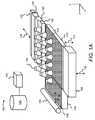
まず図1を参照すると、三次元部品を生成、構築または印刷するための例示的三次元(3D)プリンタ100の略等角図が示されている。図1に示した3Dプリンタ100は、他の構成要素をさらに含むことができ、また、本明細書に開示される3Dプリンタ100の範囲から逸脱することなく、本明細書に記載された構成要素の一部は、削除及び/又は変更されてもよいことを理解すべきである。 Referring first to FIG. 1, a schematic isometric view of an exemplary three-dimensional (3D)
3Dプリンタ100は、造形領域プラットフォーム102と、造形材料106を含む造形材料供給器104と、リコータ108とを含むものとして示されている。造形材料供給器104は、リコータ108と造形領域プラットフォーム102との間に造形材料106を配置するための容器または表面である場合がある。造形材料供給器104は、例えば、造形材料供給器104の上に配置された造形材料源(図示せず)から造形材料106を供給することができるホッパまたは表面である場合がある。追加または代替として、造形材料供給器104は、貯蔵場所から造形領域プラットフォーム102または先に形成された造形材料106の層の上に塗布すべき位置まで、造形材料106を提供し、例えば移動させる機構を含む場合がある。例えば、造形材料供給器104は、ホッパーやオーガコンベアなどを含む場合がある。一般的に言えば、三次元物体または部品は、造形材料106から生成され、造形材料106は、限定はしないが、ポリマー、金属、及びセラミックを含む任意の適当な材料から形成される場合がある。また、造形材料106は粉末の形態であってもよい。The
リコータ108は、造形材料供給器104の上を通って、及び造形領域プラットフォーム102を横切って、矢印110で示されるような方向に例えばy軸に沿って移動することにより、造形材料106を造形領域プラットフォーム102の表面上に層114として塗布することができる。層114は、造形領域プラットフォーム102にわたって実質的に均一な厚みに形成される場合がある。一例において、層114の厚みは、約90μmから約110μmまでの範囲内である場合があるが、もっと薄い層またはもっと厚い層を使用してもよい。例えば、層114の厚みは、約20μmから約200μmまで、又は約50μmから約200μmまでの範囲内である場合がある。また、リコータ108は、造形材料106の塗布の後に、造形材料供給器104に隣接する位置に戻される場合がある。追加または代替として、造形領域プラットフォーム102の反対側に、第2の造形材料供給器(図示せず)が設けられられる場合があり、リコータ108は、造形材料106の層を形成した後に、第2の造形材料供給器の上に配置される場合がある。リコータ108は、ドクターブレード、ローラ、逆回転ローラ、または、造形材料106を造形領域プラットフォーム102の上に塗布するのに適した任意の他の装置であってよい。 The recoater 108 moves the
また、3Dプリンタ100は、造形領域プラットフォーム102の上にアレイ状に配置された複数の加温装置120を含むものとして示されている。加温装置120の各々は、例えば造形材料106を所定の温度範囲内に維持すべく、塗布された造形材料106の層に熱を加えるためのランプまたは他の熱源である場合がある。加温装置120は、造形材料106の温度を造形材料106の選択的融着が容易になる比較的高い温度に維持することができる。すなわち、加温装置120は、他の方法で造形材料106を融着させることなく、融着放射線を受けたときに融着剤の液滴が提供された造形材料106を融着させることが可能となる十分高い温度に造形材料106を維持することができる。融着放射線の印加を含む種々プロセスが造形材料106に対して実施される際、加温装置120は、造形材料106を所定の温度範囲内に維持することができるように、非連続的な形で作動される場合がある。 Also, the
さらに、3Dプリンタ100は、第1の供給装置122及び第2の供給装置124を含むものとして示されている。これらの供給装置はいずれも、造形領域プラットフォーム102上の層114を横切って、例えばx軸に沿って矢印126で示される両方向に走査されることができる。例えば、第1の供給装置122は、第1の供給装置122が正のx方向126に走査される際に第1の液滴を堆積させることができ、第2の供給装置124は、第2の供給装置124が負のx方向126に走査される際に第2の液滴を堆積させることができる。第1の供給装置122及び第2の供給装置124は、サーマルインクジェットプリントヘッド又は圧電プリントヘッドなどであってよく、造形領域プラットフォーム102の幅を拡張する場合がある。第1の供給装置122及び第2の供給装置124はそれぞれ、カリフォルニア州パロアルトのヒューレット・パッカード・カンパニーから入手可能なプリントヘッド(単数又は複数)を含むことができる。図1には、第1の供給装置122と第2の供給装置124が独立した装置の形でそれぞれ示されているが、第1の供給装置122と第2の供給装置124は、同じプリントヘッド上に含まれていてもよい。例えば、第1の供給装置122は、プリントヘッド上の第1の一組のアクチュエータ及びノズルを含む場合があり、第2の供給装置124は、そのプリントヘッド上の第2の一組のアクチュエータ及びノズルを含む場合がある。 Furthermore, the
第1の供給装置122及び第2の供給装置124が造形領域プラットフォーム102の幅を拡張しない他の例では、第1の供給装置122及び第2の供給装置124は、y軸に沿ってさらに走査される場合があり、これによって、第1の供給装置122及び第2の供給装置124を造形領域プラットフォーム102上の領域の大部分にわたって配置することが可能になる。例えば、造形材料106の層114の種々の所定の領域にそれぞれの液体を堆積させるために、第1の供給装置122及び第2の供給装置124は、造形領域プラットフォーム102に隣接して第1の供給装置122及び第2の供給装置124を移動させるための可動XYステージまたは移動キャリッジ(いずれも図示せず)に取り付けられる場合がある。 In another example where the
図示されていないが、第1の供給装置122及び第2の供給装置124はそれぞれ、複数のノズルを含み、ノズルを通してそれぞれの液滴が、層114の上に噴射されることになる。第1の供給装置122は、第1の液体を堆積させることができ、第2の供給装置124は、第2の液体を堆積させることができる。第1の液体及び第2の液体は、両方とも融着剤であってもよいし、両方とも表面装飾剤であってもよく、あるいは、一方が融着剤であり、他方が表面装飾剤であってもよい。融着剤は、融着放射線(例えば、光及び/又は熱の形をしている)が印加されたときに、融着放射線を吸収し、融着剤が堆積された造形材料106を一つに融着させる液体である場合がある。表面装飾剤は、融着剤と比べて著しく少量の融着放射線しか吸収しない液体である場合がある。一例において、表面装飾剤は、表面装飾剤が堆積された造形材料106の融着を防止し、又は著しく低減することができる。他の例において、表面装飾剤は、一緒に融着された造形材料106の外側部分への着色を提供するように実施される場合がある。 Although not shown, each of the
第1の液体及び第2の液体は、放射線吸収を増強し、又は低減する様々な添加剤、及び/又は触媒をさらに含むことができる。例えば、第1の液体は、放射線吸収剤、すなわち、活性物質、金属ナノ粒子などを含むことができる。第1の液体及び第2の液体は、共溶媒、界面活性剤、殺生物剤、抗コゲーション剤、分散剤、及び/又はそれらの組み合わせのいずれかをさらに含む場合がある。 The first liquid and the second liquid can further include various additives and/or catalysts that enhance or reduce radiation absorption. For example, the first liquid can include a radiation absorber, i.e., active substance, metal nanoparticles, and the like. The first liquid and the second liquid may further comprise any of cosolvents, surfactants, biocides, anti-kogation agents, dispersants, and/or combinations thereof.
図示していないが、3Dプリンタ100は、互いに異なる放射線吸収特性を有する複数の液体を堆積させることができる種々の他の供給装置、例えばプリントヘッドをさらに含むことができる。一例として、複数の液体は、互いに異なる色を有する場合があり、また、互いに異なる化学組成(例えば、異なる反応物質及び/又は触媒)などを有する場合がある。3Dプリンタ100が複数の液体を堆積することができる例では、3Dプリンタ100は、複数のプリントヘッドを含むことができ、複数のプリントヘッドのそれぞれが、他の液体に対して異なる放射線吸収特性を有する液体を堆積させることができる。 Although not shown, the
第1の供給装置122は、造形材料106の層114内の造形材料106上に第1の液滴を選択的に供給するように制御される場合がある。第1の液滴は、層114の予め選択された領域、例えば三次元物体の一部を形成するために一つに融着されるべき造形材料106を含む種々の領域上に供給される場合がある。しかしながら、一例によれば、第1の液滴を予め選択された領域の全体に供給する代わりに、液滴の供給の際に、ギャップが設けられてもよい。ギャップは、造形材料106にヒートシンクを形成するように設けられる場合がある。すなわち、第1の供給装置122から液滴を受けていない予め選択された領域内の造形材料106は、液滴が供給された隣接する造形材料106からの熱を、例えば隣接する造形材料106からの熱流出によって吸収することができる。これに関し、融着放射線が造形材料106に印加されると、液滴が供給された造形材料106は、液滴を介したエネルギーの吸収によって加熱され、供給された液滴間のギャップ内に配置された造形材料106は、隣接する加熱された造形材料106からの熱の吸収によって加熱されることができる。 The
一例によれば、予め選択された領域内の種々の造形材料106にわたって温度スパイクが発生することを防止するために、ギャップは、液滴が供給されるべき予め選択された領域内に分散される場合がある。すなわち、予め選択された領域内の任意数の場所における造形材料106の温度が、融着放射線の印加前又は印加中に所定の閾値温度を超えるか、又は所定の閾値を超える可能性があるかどうかの判断が行われる場合がある。温度が所定の閾値を超える可能性を低減又は除去するために、ギャップは、様々な場所に分散され、それらの場所にある造形材料106の間に熱をより均一に分布させることができる。すなわち、高い温度を有する場所、または高い温度を有することが予測される場所ほど、ギャップの広い分布が与えられ、したがって、より広い面積にわたって熱が分散され、したがって、予め選択された領域内の種々の造形材料106にわたって熱的(温度的)均一性がもたらされる。造形材料106の予め選択された領域内の様々な場所についてギャップの分布を決定することができる様々な方法が、以下で詳細に説明される。According to one example, in order to prevent temperature spikes from occurring across the
第2の供給装置124は、第1の供給装置122と同様の形で制御され、第2の供給装置124により第2の液滴が供給されるべき予め選択された領域内に、種々のギャップの分布を提供することができる。また、3Dプリンタ100が他の供給装置をさらに含む場合、同様の制御機能をそのような他の供給装置にも適用することができる。ただし、第2の供給装置124が表面装飾剤の液滴を供給する他の例では、第2の供給装置124は、表面装飾剤の液滴を、堆積された第1の液滴間に形成された種々のギャップの中に堆積させるように制御される場合がある。1つには、表面装飾剤の液滴によれば、様々なギャップからの熱除去を拡大させることが可能である。 The
造形材料106の層114の選択された種々の領域上への第1の液滴及び/又は第2の液滴の堆積の後、第1の放射線発生器130及び/又は第2の放射線発生器132を実施することにより、層114内の造形材料106上に、融着放射線を印加することができる。具体的には、放射線発生器130,132を作動させ、例えば、矢印126で示される方向に沿って層114を横切って移動させることにより、造形材料106上に融着放射線を光及び/又は熱の形で印加することができる。放射線発生器130,132の例としては、紫外線(UV)、赤外線(IR)若しくは近赤外線(近IR)硬化ランプ、IR若しくは近IR発光ダイオード(LED)、可視及び近IR範囲で発光するハロゲンランプ、または、望ましい電磁波長を有するレーザーが挙げられる。放射線発生器130,132のタイプは、少なくとも部分的に、液体に使用される活性物質のタイプによる場合がある。一例によれば、第1の供給装置122、第2の供給装置124、第1の融着放射線発生器130、及び第2の融着放射線発生器132は、キャリッジ(図示せず)上に支持される場合があり、キャリッジは、造形領域プラットフォーム102の上を矢印126で示される方向に走査される場合がある。 A
複数のパスの間における液滴の付与の後、造形材料106の種々の選択された部分を1つに融着するための放射線の印加の後に、造形領域プラットホーム102を、矢印112で示されるように、例えばz軸に沿って降下させることができる。また、造形領域プラットフォーム102を横切ってリコータ108を移動させることにより、先に形成された層114の上に、造形材料106の新しい層を形成することができる。さらに、新しい造形材料106の層の各自の選択された領域上に、上述のように単一のパス及び/又は複数のパスの形で、第1の供給装置122は、第1の液滴を堆積させることができ、第2の供給装置124は、第2の液滴を堆積させることができる。上記のプロセスを三次元物体の種々の部分が所定数の層に形成されるまで繰り返すことにより、三次元物体を製造することができる。 After application of the droplets between the multiple passes, after application of radiation to fuse the various selected portions of the
さらに、造形材料の層を横切る液体堆積動作の後、または複数の造形材料の層にわたる複数回の液体堆積動作の後に、第1の供給装置122及び第2の供給装置124は、ワイピング機構134に隣接して配置される場合がある。ワイピング機構134は、第1の供給装置122及び第2の供給装置124のノズルを拭くことができ、また、もし3Dプリンタ100に含まれる場合、他の供給装置のノズルも拭くことができる。ワイピング機構134は、ワイピング機構134のクリーニングウェブ(図示せず)のような表面がノズルの外側表面と接触する位置まで移動される場合がある。供給装置122,124を所望の性能レベル以上に維持するために、ワイピング機構134は、矢印136で示されるようにz方向に移動されることができ、それによって、第1の供給装置122及び第2の供給装置124の外側表面と接触することがある造形材料106、液体、埃等のようなごみを取り除くことができる。 Further, after a liquid deposition operation across a layer of build material, or after multiple liquid deposition operations across multiple layers of build material, the
図1に詳しく示されているように、3Dプリンタ100は、造形領域プラットフォーム102、造形材料供給器104、リコータ108、加温装置120、第1の供給装置122、第2の供給装置124、放射線発生器130,132、及びワイピング機構134の動作を制御することができるコントローラ140を含む場合がある。具体的には、例えば、コントローラ140は、種々のアクチュエータ(図示せず)を制御することにより、3Dプリンタ100の種々の構成要素の様々な動作を制御することができる。コントローラ140は、コンピューティング装置、半導体ベースのマイクロプロセッサ、中央演算処理装置(CPU)、特定用途向け集積回路(ASIC)、及び/又は他のハードウェアデバイスである場合がある。図示していないが、コントローラ140は、通信ラインを介して3Dプリンタ100の種々の構成要素に接続される場合がある。 As shown in detail in FIG. 1, the
また、コントローラ140は、データ記憶装置142と通信するものとして示されている。データ記憶装置142は、3Dプリンタ100によって印刷されるべき三次元物体に関するデータを含む場合がある。例えば、このデータは、三次元物体を形成するために、第1の供給装置122が第1の液体を堆積させ、第2の供給装置124が第2の液体を堆積させるべき、各造形材料層内の場所を含む場合がある。一例において、コントローラ140は、このデータを使用して、第1の供給装置122及び第2の供給装置124が第1及び第2の液体の滴をそれぞれ堆積させる造形材料層の各々における場所を制御することができる。 The
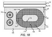
次に、図1Bを参照すると、一例による、造形材料106の層114の種々の予め選択された領域に配置された造形材料106から形成されている途中の複数の部品160,162の略平面図が示されている。図示のように、第1の部品160は、小さい方の部品162に比べて比較的大きいサイズを有する場合がある。また、第1の部品160及び第2の部品162は、第1の供給装置122による、造形材料106の層114の種々予め選択された領域上への例えば融着剤の液滴のような液滴164の付与によって形成される場合がある。例えば、図1Bは、第1の供給装置122が予め選択された領域上に液滴164を供給した後、それらの領域に融着エネルギーを印加する前の状態を示している場合がある。Referring now to FIG. 1B, a schematic plan view of a plurality of
また、第1の部品160は、液滴164間に分散されたギャップ166を含むものとして示されている。具体的には、ギャップ166は、第1の部品160の外側部分及び内側部分170,172と比較して、第1の部品160の中央部分168に沿って高度に密集しているように示されている。1つには、ギャップ166をこのような形で形成することができるのは、第1の部品160の中央部分168の周りには通常、外側部分170及び内側部分170よりも多量の液滴164が存在していることから、第1の部品160の中央部分168は、融着放射線の印加中に、外側部分170及び内側部分172と比べて多量のエネルギーを吸収することができるからである。 Also, the
同様の理由から、第2の部品162を形成するために供給される液滴164は、ギャップを含まない場合がある。なぜなら、第2の部品162が形成されるべき領域に位置する造形材料106は、それらの造形材料106に付与された液滴164の量が少ないため、所定の閾値温度を超えない場合があるからである。ただし、他の例では、任意サイズの部品を形成するために、造形材料106上に供給された液滴164の間にギャップ166を設ける場合がある。 For similar reasons, the
次に、図1Cを参照すると、第1の部品160に融着放射線を印加した後の、第1の部品160の一部を横切る図1Bの断面174に沿った温度分布を示す例示的グラフ180が示されている。すなわち、グラフ180は、断面174内の温度がかなり一定のままであること、すなわち、第1の部品160内の造形材料106が、互いに熱的に均一であることを示している。例えば、断面174内の異なる位置に比較的小さい温度差しかない場合、例えば、約1℃から約10℃までの範囲内である場合、熱均一性があるとみなされる場合がある。他の例では、温度差が、例えば、約2℃から約5℃までの間である場合、熱均一性があるとみなされる場合がある。1つには、ギャップ166によれば、液滴164を受けた造形材料106の余分な熱を、液滴164を受けていない造形材料106へと放散させることができ、したがって、第1の部品160内の種々の造形材料106にわたって均一な熱分布を生じさせることができる。さらに、液滴164を受けていない造形材料106を、この余分な熱の吸収によって一つに融着させることができ、同時に、造形材料106の一部における温度スパイク又やピークを防止することができる。 Referring now to FIG. 1C, an
部品160の種々の選択された領域内にギャップ166を形成することによって、層114内の部品160を形成する造形材料106を、互いに熱的に均一な状態にすることができ、その結果、温度スパイク(例えば、低温からの所定の温度を大きく上回る温度差)が防止され、または最小限に抑えられる場合がある。部品160を形成する造形材料106の全体にわたって熱的均一性を維持することにより、例えば、それらの造形材料106の周りの他の造形材料106への熱流出の量を大幅に低減することができる。さらに、その後に堆積された造形材料106の層内の造形材料106への熱流出の量も、大幅に低減することができる。すなわち、ある一組の造形材料106から別の一組の造形材料への望ましくない熱の移動の量を大幅に低減することができ、したがって、造形材料106の複数の層114における種々の部品のより正確な形成が可能になる。 By forming the
液滴164を造形材料106上に供給する単一の供給デバイス122を特に参照したが、他の例では、図1Bは、複数の供給装置122,124が、第1の部品160を形成するために、層114の予め選択された領域に供給される液滴間に制御されたギャップ166を有するように、それぞれ液滴164を供給した後の状態を示すものとして解釈されてもよい。 Although particular reference was made to a
次に、図2を参照すると、例示的コンピューティング装置200の略ブロック図が示されている。一例によれば、コンピューティング装置200は、3Dプリンタ100の一部として実施される場合がある。例えば、コンピューティング装置200は、3Dプリンタ100のコマンドモジュール又は他の制御システムである場合がある。別の例では、コンピューティング装置200は、3Dプリンタ100とは別個であってもよく、例えば、パーソナルコンピュータ、ラップトップコンピュータ、サーバコンピュータなどであってもよい。図2に示したコンピューティング装置200は、他の構成要素をさらに含む場合があり、また、本明細書に開示されたコンピューティング装置200の範囲から逸脱することなく、本明細書に記載された構成要素の一部は、除去及び/又は修正される場合がある。 2, a schematic block diagram of an
コンピューティング装置200は、コントローラ140及びデータ記憶装置142を含むものとして示されており、これらは、図1に関して上で図示説明したコントローラ140及びデータ記憶装置142と同じであってもよい。したがって、図2に示したコントローラ140及びデータ記憶装置142は、詳細には説明されないが、3Dプリンタ100に関して上で行ったコントローラ140及びデータ記憶装置142の説明は、コンピューティング装置200に関するそれらの構成要素も、説明することを意図している。
また、コンピューティング装置200は、コントローラ140によって実行可能な機械読み取り可能命令212〜228が記憶されたコンピュータ読み取り可能記憶媒体210をさらに含むことができる。より具体的には、コントローラ140は、命令212〜228をフェッチ、デコード、及び実行することにより、印刷されるべき三次元物体に関するデータを入手(212)し、供給装置によって形成されるべき部品についての印刷データを入手(214)し、形成されるべき部品の特性/造形材料の温度プロファイルを識別(216)し、液滴の供給の際に形成されるべきギャップの分布を決定(218)し、印刷データを更新(220)し、供給装置(単数又は複数)を制御(222)し、放射線発生器(単数又は複数)を制御(224)し、造形領域プラットフォームを制御(226)し、リコータを制御(228)することができる。命令を読み出して実行することの代りに、又はそれに加えて、コントローラ140は、命令212〜228の機能を実施するための種々の構成要素を含む任意数の電子回路を含む場合がある。いずれにしても、上記のように、コントローラ140は、種々の命令信号を通信ラインを介して3Dプリンタ100の種々の構成要素に伝達し、それらの構成要素が本明細書に記載された形で動作するようにすることができる。 In addition, the
コンピュータ読み取り可能記憶媒体210は、種々の実行可能命令を含み、若しくは記憶する任意の電子的、磁気的、光学的、又は他の物理的記憶装置であってよい。例えば、コンピュータ読み取り可能記憶媒体210は、ランダムアクセスメモリ(RAM)、電気的に消去可能なプログラマブル読み取り専用メモリ(EEPROM)、記憶装置、光ディスクなどである場合がある。コンピュータ読み取り可能記憶媒体210は、機械読み取り可能な非一時的記憶媒体であってもよく、ここで、「非一時的」という語は、一時的伝搬信号を包含しない。 Computer readable storage media 210 may be any electronic, magnetic, optical, or other physical storage device containing or storing various executable instructions. For example, computer readable storage medium 210 may be random access memory (RAM), electrically erasable programmable read only memory (EEPROM), storage, optical disk, or the like. Computer readable storage media 210 may be machine readable non-transitory storage media, where the term "non-transitory" does not include transitory propagated signals.
図3及び図4にそれぞれ示した方法300及び400に関して、コンピューティング装置200を実施することができる様々な方法をさらに詳細に説明する。具体的には、図3及び図4は、ヒートシンクを形成するように分散された種々のギャップを含むように液滴の供給を制御する例示的方法300及び400をそれぞれ示している。ヒートシンクは、予め選択された領域にある造形材料106を互いに熱的に均一にする。方法300及び400が一般化された例を表している場合があること、並びに、方法300及び400の範囲から逸脱することなく、他の動作が追加され、または、既存の動作が削除され、修正され、若しくは並び替えられてもよいことは、当業者には明らかである。 Various methods by which
方法300及び400の説明は、例示のために、図1Aに示した3Dプリンタ100、図1Bに示した例、及び、図2に示したコンピューティング装置200を参照して行われた。しかしながら、方法300及び400の範囲から逸脱することなく、方法300及び400のいずれか一方又は両方を実施するために、他の構成を有する3Dプリンタ及びコンピューティング装置を実施してもよいことは、明らかである。 The description of the
方法300及び400のいずれか一方の実行に先立って、または、方法300及び400の種々の部分として、コントローラ140は、コンピュータ読み取り可能媒体210に記憶された命令212を実行し、印刷されるべき三次元物体に関するデータを入手することができる。例えば、コントローラ140は、データ記憶装置142に記憶された印刷されるべき三次元物体に関するデータを入手することができる。コントローラ140は、三次元物体を形成するために、形成されるべき造形材料106の層114の数、及び、造形材料106の各層上の第1の液滴及び/又は第2の液滴が堆積されるべき場所を決定することができる。コントローラ140は、各層の処理動作中に、リコータ108、第1の供給装置122、第2の供給装置124、第1の融着放射線発生器130、及び第2の融着放射線発生器132の各々を、造形領域プラットフォーム102を横切って何時移動させるべきかをさらに決定することができる。ただし、他の例では、3Dプリンタ100の外部にある処理装置(図示せず)が、種々の命令を実行することにより、三次元物体データを入手し、これらの決定を行ってもよい。こうした例では、処理装置は、この情報をコントローラ140に伝達し、コントローラ140は、方法300及び400のいずれか一方又は両方を実行する際に、この情報を実施することができる。 Prior to execution of either one of the
まず図3を参照すると、ブロック302では、造形材料106の層114上の予め選択された領域上に液滴164を供給するための、供給装置122のための命令を含む印刷データを入手することができる。コントローラ140は、データ記憶装置142又は外部情報源(図示せず)からこの印刷データを入手することができ、印刷データは、層114に部品160を形成するために、予め選択された領域上に液滴164を供給するための種々の命令を含む場合がある。コントローラ140はさらに、他の層114上に液滴164を供給するための印刷データを入手する場合がある。 Referring first to FIG. 3, at
一例によれば、印刷データは、部品160を形成するために、層114に対して液滴がどこに堆積されるべきかを示す場合がある。この点に関し、印刷データは、第1の供給装置122が層114を横切って走査される際に、第1の供給装置122のノズルから液滴164が噴射されるべきタイミングを制御し、液滴164が層114の予め選択された領域にある造形材料106の上に供給されるようにする、種々の命令を含む場合がある。 According to one example, the print data may indicate where droplets should be deposited relative to layer 114 to form
ブロック304では、予め選択された領域内の液滴164の供給の際にギャップ166が形成されるべき分布を、印刷データに基づいて決定することができる。ギャップ166が形成されるべき分布の決定は、ギャップ166のサイズ、含まれるべきギャップ166の数、ギャップ166が設けられるべき場所等の決定を含む場合がある。上述のように、ギャップ166は、予め選択された領域内の種々の造形材料106にわたって熱的均一性をもたらすヒートシンクを造形材料106に形成することができる。例えば、コントローラ140は、命令218を実行することにより、ギャップ166から形成されたヒートシンクによって、予め選択された領域内の種々の造形材料106にわたって熱的均一性がもたらされるように、液滴164の供給の際にギャップ166が形成されるべき分布を決定する。一例によれば、コントローラ140は、印刷データに基づいて分布を決定することができ、印刷データは、部品160を形成するために、液滴164が堆積されるべき予め選択された領域のサイズ及び/又は幾何学的形状のような情報を含む場合がある。 At
例えば、コントローラ140は、部品160が所定の最小サイズよりも大きい部分を含むか否かを判定し、そのような所定の最小サイズよりも大きい部品160の部分については、ギャップ166を有するように液滴164を供給すべきであることを決定する場合がある。また、コントローラ140は、それらの部分のサイズに対応するようにギャップ166の分布を決定する場合がある。すなわち、コントローラ140は、大きい部分ほど、大きい分布のギャップ166を有するべきであり、小さい部分ほど、小さい分布のギャップ166を有するべきであると決定する場合がある。さらに、コントローラ140は、それらの部分のサイズ及び/又は幾何学的形状に基づいてギャップ166の配置を決定する場合がある。例えば、コントローラ140は、最も高い温度を有する可能性が高い部分の場所に比較的高い密度のギャップ166が配置されるべきことを決定する場合がある。そのような場所としては、例えば、それらの部分の中心の場所が挙げられる。この例では、比較的高い密度のギャップ166が、それらの部分の縁部に比べてそれらの部分の中心付近に形成される場合がある。 For example, the
一例によれば、所定の最小サイズ並びにギャップ166の分布は、造形材料106、及び/又は3Dプリンタ100の構成要素の種々の特性に基づいて決定される場合がある。例えば、種々のタイプの材料から形成される種々の造形材料106、並びに、種々のタイプの融着放射線発生器を有する種々の3Dプリンタについて、所定の最小サイズ並びにギャップ166の分布は、変わる場合がある。具体例として、所定の最小サイズ並びにギャップ166の分布は、造形材料と3Dプリンタ構成要素の種々の組み合わせの試験によって決定される場合がある。試験の結果は、データ記憶装置142に記憶される場合があり、コントローラ140は、特定の3Dプリンタによる特定の部品の形成のための液滴164の供給時にギャップ166が形成されるべき分布を決定する際に、この情報を入手する場合がある。他の例では、コントローラ140は、予測温度の計算、及び予測温度とギャップのサイズ及び分布との相関のような、他の方法でギャップ166の分布を決定する場合がある。 According to one example, the predetermined minimum size as well as the distribution of
ブロック306では、決定された分布でギャップ166を形成しながら液滴164を予め選択された領域内に供給するように、供給装置122を制御することができる。コントローラ140は、命令222を実行することにより、ギャップ166を形成しながら液滴164を供給するように、供給装置122を制御することができる。以下で詳しく説明されるように、コントローラ140は、ギャップ166が形成されることになる領域上への液滴164の供給を防止するための命令が印刷データに含まれるように印刷データを修正することができ、供給装置122を制御する際に、修正された印刷データを実施することにより液滴164を供給する場合がある。一例によれば、コントローラ140は、ギャップ166が形成されべき場所、例えば、ギャップ166を形成すべく供給装置122が層114を横切って走査される際にノズルの発射を防止するタイミング、を識別するマスクを生成することができる。コントローラ140は、液滴の供給の際に、マスクを適用してギャップ166の形成を制御する場合がある。さらに、コントローラ140は、第2の供給装置124が表面装飾剤の液滴を供給する場所を識別する第2のマスクを生成する場合があり、この場所は、ギャップ166が形成された場所であってもよい。コントローラ140は、第2の液滴の供給の際に、第2のマスクを適用して、表面装飾剤の液滴の堆積をギャップ166のうちの選択されたものの中に制限する場合がある。 At
次に図4を参照すると、ブロック402において、コントローラ140は、造形材料106の層114上の予め選択された領域上に液滴164を供給するための供給装置122のための命令を含む印刷データを入手することができる。図4のブロック302に関して上で説明したように、コントローラ140は、命令214を実行することにより、予め選択された領域内の造形材料106から形成されるべき部品160の印刷データを入手することができる。 Referring now to FIG. 4, at
ブロック404では、様々な特性を識別することができる。例えば、コントローラ140は、命令216を実行することにより、上述のように、部品160の種々の部分のサイズ及び幾何学的形状のような、形成されるべき部品160の種々の特性を識別することができる。また、コントローラ140は、命令216を実行することにより、造形材料106の様々な温度プロファイルを識別することができ、例えば、層114の様々な領域に位置する造形材料106の現在の温度(例えば、造形材料の温度プロファイル)、造形材料106に対する融着放射線の印加中に層114内の造形材料106が到達すると予測される温度、及び、先に処理された造形材料106の層114内の温度を示す履歴的温度マップなどを識別することができる。コントローラ140は、例えば温度センサによってデータ記憶装置142に記憶されたデータから温度プロファイル情報を識別する場合がある。 At
ブロック406では、識別された特性に基づいて、予め選択された領域の第1の場所内の液滴164の供給の際にギャップ166が形成されるべき分布を決定することができる。例えば、コントローラ140は、命令218を実行することにより、印刷データ及び/又は識別された温度プロファイルに基づいて、ギャップ166が形成されるべき分布を決定し、部品160を形成するための種々の造形材料106にわたって熱的均一性を維持することができる。また、コントローラ140は、予め選択された領域内の特定の場所、例えば予め選択された領域の中心の場所について、ギャップ166の分布を決定する場合がある。例えば、コントローラ140は、高い温度を有する場所ほど、その場所に広い分布のギャップ166が形成されるべきであり、低い温度を有する場所ほど、その場所に狭い分布のギャップ166が形成されるべきであることを決定する場合がある。コントローラ140は、様々な位置における予測温度に基づいて、同様の決定を行ってもよい。 At
ブロック408では、ギャップ166が形成されるべき分布を含むように印刷データを更新することができる。コントローラ140は、命令220を実行することにより、印刷データを更新することができる。 At
ブロック410では、コントローラ140は、予め選択された領域のさらに別の場所について、ギャップ166の分布をさらに形成すべきかどうかを決定することができる。予め選択された領域のさらに別の場所についてギャップ166の分布をさらに形成すべきであるという決定に応答し、コントローラ140は、別の場所についてのギャップ166の分布をさらに決定することができる。例えば、コントローラ140は、別の場所は、多くのヒートシンクを必要としないと判断する場合があり、別の場所については、ギャップ166のより狭い分布を決定する場合がある。さらに、コントローラ140は、ギャップ166のこの更なる分布を用いて、印刷データを更新する場合がある。 At
コントローラ140は、予め選択された領域内の複数の場所の各々についてギャップ166の分布が決定され、これらのギャップの分布を用いて印刷データが更新されるまで、ブロック406〜410を繰り返すことができる。ブロック410における「いいえ」状態の後、ブロック412に示されるように、供給装置122を制御することにより、決定された分布でギャップ166を形成しながら液滴164を予め選択された領域内に供給することができる。コントローラ140は、命令222を実行し、供給装置122を制御することにより、更新された印刷データに基づいて液滴164を供給すること、したがって、液滴164の供給の際にギャップ166の選択的形成を生じさせることができる。また、コントローラ140は、命令222を実行し、第2の供給装置124を制御することにより、融着剤の液滴をギャップ166の様々なものの中に供給することができる。The
ブロック414では、コントローラ140は、命令224を実行し、融着放射線発生器130,132の一方又は両方を制御することにより、層114内の造形材料106上に融着放射線を提供することができる。融着放射線は、液滴164が堆積された造形材料106を一つに融着させ、同時に、ギャップ166内に配置された造形材料106の一部に、他の造形材料106からの熱流出によって熱を吸収させることができ、これによってさらに、それらの造形材料106を一つに融着させることができる。 At
ブロック416では、コントローラ140は、造形材料106のさらに別の層114が形成されるべきか否かを決定することができる。コントローラ140は、例えば、印刷されるべき3D部品に関する入手した情報に基づいて、この決定を行うことができる。さらに別の層が形成されるべきであるという決定に応答して、ブロック416に示されるように、造形材料106の次の層を、先の層114の上に塗布することができる。例えば、コントローラ140は、命令226を実行することにより、造形領域プラットフォーム102を制御して下方に移動させることができ、命令228を実行することにより、リコータ108を制御して、先の層114を横切って造形材料106をさらに塗布することができる。さらに、ブロック402〜418は、形成されるべき他の層が無くなるまで繰り返されることができ、その時点で、ブロック420に示されるように、方法400は終了することができる。At
本明細書では、単一の供給装置122について特に言及しているが、本開示の範囲から逸脱することなく、供給される液滴にギャップを形成しながらそれぞれの液滴を供給するためにさらに別の供給装置124を実施してもよいものと理解すべきである。 Although particular reference is made herein to a
方法300及び400において説明した動作の一部又は全部は、ユーティリティ、プログラム、又はサブプログラムとして、任意の所望のコンピュータアクセス可能媒体に含まれる場合がある。また、方法300及び400は、アクティブ及び非アクティブの両方を含む様々な形で存在することがあるコンピュータプログラムによって具体化される場合がある。例えば、それらは、ソースコード、オブジェクトコード、実行可能コード又は他のフォーマットを含む機械読み取り可能命令として存在する場合がある。上記はいずれも、非一時的コンピュータ読み取り可能記憶媒体上に具体化されてもよい。非一時的コンピュータ読み取り可能記憶媒体の例としては、コンピュータシステムのRAM、ROM、EPROM、EEPROM、及び磁気又は光ディスク又はテープが挙げられる。したがって、上で説明した機能を実行することが可能な電子装置はいずれも、上に列挙した機能を実施することができるものと理解すべきである。 Some or all of the acts described in
本開示の全体を通じて具体的に記載されているが、本開示の代表例は、広範囲の用途にわたって有用性を有し、上記の説明は限定的であると解釈されるべきものではなく、本開示の種々の態様の例示的説明として提供されるものである。本明細書に図示説明されているものは、開示の一例とその変形例の一部である。本明細書で使用される用語、説明、及び図は、例示のためだけに記載されており、限定を意味するものではない。本開示の思想及び範囲内で多くの変形が可能であり、それらは、以下の特許請求の範囲及びそれらの均等によって定義されることが意図されている。全ての用語は、特に明記しない限り最も広い合理的意味である。
Although specifically described throughout this disclosure, the representative examples of this disclosure have utility over a wide range of applications and the above description should not be construed as limiting, and the present disclosure Is provided as an exemplary description of various aspects of the invention. What has been illustrated and described herein is part of an example disclosure and variations thereof. The terms, descriptions and figures used herein are set forth by way of illustration only and are not meant as limitations. Many variations are possible within the spirit and scope of this disclosure, which are intended to be defined by the following claims and their equivalents. All terms have their broadest reasonable meaning unless otherwise specified.
Claims (15)
Translated fromJapanese前記供給装置が液滴を供給すべき前記造形材料の層上の予め選択された領域を決定し、印刷データに基づいて、前記予め選択された領域内への前記液滴の前記供給の際にギャップが形成されるべき分布を決定し、前記供給装置を制御して、前記決定された分布で前記ギャップを形成しながら前記液滴を前記予め選択された領域内に供給する、コントローラと
を含み、前記ギャップが、前記予め選択された領域内の前記造形材料にわたって温度スパイクが発生することを防止するヒートシンクを前記造形材料に形成し、
前記ギャップが形成されるべき分布を決定することは、前記ギャップのサイズ、前記予め選択された領域に含まれるべき前記ギャップの数、及び、前記ギャップが設けられるべき場所を決定することを含み、
前記液滴は、融着剤の液滴であり、
前記コントローラは、前記ギャップが形成されるべき分布を、前記予め選択された領域の中心部分に形成されるべき前記ギャップの密度が、前記予め選択された領域の縁部に比べて高くなるように決定する、3次元(3D)プリンタ。A supply device for selectively supplying droplets onto the layer of building material,
The supply device determines a preselected area on the layer of build material to which a droplet is to be supplied, and based on print data, during the supply of the droplet into the preselected area. A controller for determining a distribution in which a gap is to be formed and controlling the supply device to supply the droplet into the preselected region while forming the gap with the determined distribution. Forming a heat sink in the build material that prevents temperature spikes from occurring across the build material in the preselected region;
Determining the distribution to the gap is formed, the size of the gap, the number of the gaps to be included in the pre-selected region, and,viewed including determining where to the gap is provided,
The droplet is a droplet of a fusion agent,
The controller controls the distribution in which the gaps are formed such that the density of the gaps to be formed in the central portion of the preselected region is higher than the edge of the preselected region. A three-dimensional (3D) printer that determines.
前記コントローラは、前記予め選択された領域内の前記造形材料にわたる温度スパイクの防止がもたらされるように、前記第1の場所にギャップが形成されるべき第1の分布を決定し、前記第2の場所にギャップが形成されるべき第2の分布を決定する、請求項3に記載の3Dプリンタ。The temperature profile identifies a first location having a higher temperature in the preselected area and a second location having a lower temperature in the preselected area,
The controller determines a first distribution in which a gap should be formed at the first location so as to provide prevention of temperature spikes across the build material in the preselected area, the second distribution The 3D printer according to claim 3, wherein the 3D printer determines a second distribution in which a gap is to be formed in the place.
前記コントローラは、前記履歴的温度マップに基づいて、前記ギャップが形成されるべき前記分布を決定し、
前記コントローラは、前記履歴的温度マップに基づいて、第1の温度に到達すると予測される前記予め選択された領域内の第1の場所を決定するとともに、前記履歴的温度マップに基づいて、第2の温度に到達すると予測される前記予め選択された領域内の第2の場所を決定し、
前記コントローラは、前記予測された第1の温度に基づいて、前記決定された第1の場所にギャップが形成されるべき第1の分布を決定し、前記予測された第2の温度に基づいて、前記決定された第2の場所にギャップが形成されるべき第2の分布を決定する、請求項1または請求項2に記載の3Dプリンタ。The controller further obtains a historical temperature map,
The controller determines the distribution in which the gap is to be formed based on the historical temperature map,
The controller determines a first location within the preselected region predicted to reach a first temperature based on the historical temperature map, and a first location based on the historical temperature map. Determining a second location within the preselected region predicted to reach a temperature of 2;
The controller determines a first distribution in which a gap should be formed at the determined first location based on the predicted first temperature, and based on the predicted second temperature. The 3D printer according to claim 1 or 2, which determines a second distribution in which a gap is to be formed at the determined second location.
前記第2の液滴は、表面装飾剤の液滴からなり、
前記コントローラはさらに、前記別の供給装置を制御して、前記液滴間に形成された前記ギャップ内に第2の液滴を供給する、請求項1〜5の何れか一項に記載の3Dプリンタ。Further comprising another supply device for selectively supplying the second droplet,
The second droplet comprises a droplet of surface decoration,
The 3D according to any one of claims 1 to 5, wherein the controller further controls the other supply device to supply a second droplet in the gap formed between the droplets. Printer.
前記コントローラは、融着放射線の印加中に第1の温度に到達すると予測される前記予め選択された領域内の第1の場所を、前記第1の場所の位置、及び前記決定された前記予め選択された領域のサイズに基づいて識別し、
前記コントローラは、前記予測された第1の温度に基づいて、前記予め選択された領域内の前記第1の場所に前記ギャップが形成されるべき前記分布を決定する、請求項1〜5の何れか一項に記載の3Dプリンタ。The controller determines the size of the preselected area to which the droplets are to be dispensed,
The controller determines a first location within the preselected region that is predicted to reach a first temperature during application of fusing radiation, a location of the first location, and the determined pre-determined location. Identify based on the size of the selected area,
The controller of any of claims 1-5, wherein the controller determines the distribution in which the gap is to be formed at the first location within the preselected region based on the predicted first temperature. The 3D printer according to 1 above.
前記マスクは、前記ギャップを形成すべく前記供給装置が前記造形材料の層を横切って走査される際に、前記供給装置のノズルの発射を防止するタイミングを識別し、
前記コントローラは、前記供給装置を制御する際に前記マスクを適用して、前記ギャップを形成しながら前記液滴を前記予め選択された領域内に供給する、請求項1〜5の何れか一項に記載の3Dプリンタ。The controller generates a mask to be applied to print data for the dispensing device in selectively dispensing the droplets,
The mask identifies when to prevent firing of a nozzle of the dispenser as the dispenser is scanned across the layer of build material to form the gap,
The controller applies the mask when controlling the supply device to supply the droplet into the preselected region while forming the gap. 3D printer described in.
前記印刷データに基づいて、前記予め選択された領域内の前記液滴の前記供給の際にギャップが形成されるべき分布を決定し、前記ギャップが、前記予め選択された領域内の前記造形材料にわたって熱的均一性をもたらすヒートシンクを前記造形材料に形成し、
前記供給装置を制御して、前記決定された分布で前記ギャップを形成しながら前記液滴を前記予め選択された領域内に供給すること
を含み、
前記ギャップが形成されるべき分布を決定することは、前記ギャップのサイズ、前記予め選択された領域に含まれるべき前記ギャップの数、及び、前記ギャップが設けられるべき場所を決定することを含み、
前記液滴は、融着剤の液滴であり、
前記ギャップが形成されるべき分布は、前記予め選択された領域の中心部分に形成されるべき前記ギャップの密度が、前記予め選択された領域の縁部に比べて高くなるように決定される、方法。Obtaining print data including instructions for a dispenser to dispense droplets onto preselected areas on a layer of build material,
Based on the print data, determine a distribution in which a gap should be formed during the supply of the droplets in the preselected area, the gap being the shaping material in the preselected area. Forming a heat sink in the build material that provides thermal uniformity across the
Controlling the supply device to supply the droplets into the preselected region while forming the gap with the determined distribution,
Determining the distribution to the gap is formed, the size of the gap, the number of the gaps to be included in the pre-selected region, and,viewed including determining where to the gap is provided,
The droplet is a droplet of a fusion agent,
The distribution in which the gap is to be formed is determined such that the density of the gap to be formed in the central portion of the preselected region is higher than the edge of the preselected region . Method.
前記液滴の前記供給の際にギャップが形成されるべき分布を決定することは、前記予め選択された領域のサイズ及び前記予め選択された領域の幾何学的形状のうちの前記識別された少なくとも一方に基づいて、前記分布を決定することを含む、請求項9に記載の方法。Further comprising identifying at least one of a size of the preselected region and a geometric shape of the preselected region,
Determining the distribution in which a gap is to be formed during the delivery of the droplets comprises determining at least the size of the preselected area and the identified shape of the preselected area. The method of claim 9, comprising determining the distribution based on one.
前記液滴の前記供給の際にギャップが形成されるべき分布を決定することは、前記予め選択された領域内の前記造形材料の前記識別された温度プロファイル及び前記予測された温度プロファイルのうちの前記少なくとも一方に基づいて、前記分布を決定することをさらに含む、請求項9に記載の方法。Further comprising at least one of identifying and predicting a temperature profile of the build material within the preselected region,
Determining the distribution in which a gap should be formed during the delivery of the droplets comprises determining between the identified temperature profile and the predicted temperature profile of the build material within the preselected region. The method of claim 9, further comprising determining the distribution based on the at least one.
前記予め選択された領域の第1の部分にギャップが形成されるべき第1の分布を決定し、
前記予め選択された領域の第2の部分にギャップが形成されるべき第2の分布を決定すること
をさらに含む、請求項10に記載の方法。Determining the distribution in which a gap should be formed during the delivery of the droplets is
Determining a first distribution in which a gap is to be formed in a first portion of the preselected region,
11. The method of claim 10, further comprising: determining a second distribution in which a gap should be formed in a second portion of the preselected area.
前記マスクは、前記ギャップを形成すべく前記供給装置が前記造形材料の層を横切って走査される際に、前記供給装置のノズルの発射を防止するタイミングを識別し、
前記供給装置を制御することは、前記供給装置を制御する際に前記マスクを適用して、前記ギャップを形成しながら前記液滴を前記予め選択された領域内に供給することをさらに含む、請求項10に記載の方法。Further comprising generating a mask to be applied to the print data for the dispensing device in selectively dispensing the droplets,
The mask identifies when to prevent firing of a nozzle of the dispenser as the dispenser is scanned across the layer of build material to form the gap,
Controlling the dispenser further comprises applying the mask when controlling the dispenser to dispense the droplet into the preselected region while forming the gap. Item 10. The method according to Item 10.
造形材料の層上の予め選択された領域上に液滴を印刷するための印刷データを入手させ、
前記印刷データに基づいて、前記予め選択された領域上への前記液滴の前記印刷の際に含めるべきギャップの分布を決定させ、前記ギャップが、前記予め選択された領域内の前記造形材料にわたって熱的均一性を確保するヒートシンクを、前記造形材料に形成し、
前記液滴の前記印刷の際に、前記決定された分布のギャップが含まれるように前記印刷データを修正させるものであり、
前記ギャップの分布を決定することは、前記ギャップのサイズ、前記予め選択された領域に含まれるべき前記ギャップの数、及び、前記ギャップが設けられるべき場所を決定することを含み、
前記液滴は、融着剤の液滴であり、
前記ギャップが形成されるべき分布は、前記予め選択された領域の中心部分に形成されるべき前記ギャップの密度が、前記予め選択された領域の縁部に比べて高くなるように決定される、非一時的コンピュータ読み取り可能媒体。A non-transitory computer-readable medium having machine-readable instructions stored thereon, which when executed by a processor, causes the processor to:
Obtaining print data for printing droplets on preselected areas on a layer of build material,
Determining a distribution of gaps to be included in the printing of the droplets on the preselected region based on the print data, the gap extending across the build material in the preselected region. A heat sink for ensuring thermal uniformity is formed on the molding material,
Modifying the print data so that the gap of the determined distribution is included during the printing of the droplets,
Determining the distribution of the gap, the size of the gap, the number of the gaps to be included in the pre-selected region, and,viewed including determining where to the gap isprovided,
The droplet is a droplet of a fusion agent,
The distribution in which the gap is to be formed is determined such that the density of the gap to be formed in the central portion of the preselected region is higher than the edge of the preselected region . Non-transitory computer-readable medium.
前記修正された印刷データを適用して供給装置を制御させ、前記決定された分布のギャップを得ながら前記液滴を前記層上の前記予め選択された領域に印刷する、請求項14に記載の非一時的コンピュータ読み取り可能媒体。The machine-readable instructions further direct the processor to determine the density.
15. The modified print data is applied to control a dispenser to print the droplets in the preselected area on the layer while obtaining the determined distribution gap. Non-transitory computer-readable medium.
Applications Claiming Priority (1)
| Application Number | Priority Date | Filing Date | Title |
|---|---|---|---|
| PCT/US2016/032109WO2017196346A1 (en) | 2016-05-12 | 2016-05-12 | 3d printing heat sinks |
Publications (2)
| Publication Number | Publication Date |
|---|---|
| JP2019514741A JP2019514741A (en) | 2019-06-06 |
| JP6725694B2true JP6725694B2 (en) | 2020-07-22 |
Family
ID=60267066
Family Applications (1)
| Application Number | Title | Priority Date | Filing Date |
|---|---|---|---|
| JP2018556861AExpired - Fee RelatedJP6725694B2 (en) | 2016-05-12 | 2016-05-12 | 3D printing of heat sink |
Country Status (7)
| Country | Link |
|---|---|
| US (1) | US20190168458A1 (en) |
| EP (1) | EP3426467B1 (en) |
| JP (1) | JP6725694B2 (en) |
| KR (1) | KR102207405B1 (en) |
| CN (1) | CN109070474B (en) |
| BR (1) | BR112018072035A2 (en) |
| WO (1) | WO2017196346A1 (en) |
Families Citing this family (9)
| Publication number | Priority date | Publication date | Assignee | Title |
|---|---|---|---|---|
| WO2019117963A1 (en) | 2017-12-15 | 2019-06-20 | Hewlett-Packard Development Company, L.P. | Parts packing for a build volume |
| US10842026B2 (en)* | 2018-02-12 | 2020-11-17 | Xerox Corporation | System for forming electrical circuits on non-planar objects |
| US11577463B2 (en)* | 2019-03-15 | 2023-02-14 | Hewlett-Packard Development Company, L.P. | Patterns on objects in additive manufacturing |
| EP3840937B1 (en) | 2019-03-15 | 2023-07-26 | Hewlett-Packard Development Company, L.P. | Coloured object generation |
| WO2020222794A1 (en) | 2019-04-30 | 2020-11-05 | Hewlett-Packard Development Company, L.P. | Colored object generation |
| US11214010B2 (en) | 2019-07-11 | 2022-01-04 | Hewlett-Packard Development Company, L.P. | Roller control for a 3D printer |
| US20210276738A1 (en)* | 2020-03-03 | 2021-09-09 | The Boeing Company | Space vehicle comprising cooling system |
| SE545644C2 (en)* | 2021-04-22 | 2023-11-21 | Sandvik Machining Solutions Ab | Additive manufacturing device and method for controlling an additive manufacturing device |
| FR3125979B1 (en)* | 2021-08-09 | 2023-07-14 | Cogit Composites | Installation for additive manufacturing by deposition of molten wire comprising an extrusion nozzle and a device for measuring and thermal control of the process. |
Family Cites Families (9)
| Publication number | Priority date | Publication date | Assignee | Title |
|---|---|---|---|---|
| US6905645B2 (en)* | 2002-07-03 | 2005-06-14 | Therics, Inc. | Apparatus, systems and methods for use in three-dimensional printing |
| GB201109045D0 (en)* | 2011-05-31 | 2011-07-13 | Warwick Ventures | Additive building |
| US20140255666A1 (en)* | 2013-03-06 | 2014-09-11 | University Of Louisville Research Foundation, Inc. | Powder Bed Fusion Systems, Apparatus, and Processes for Multi-Material Part Production |
| KR101872628B1 (en)* | 2014-01-16 | 2018-06-28 | 휴렛-팩커드 디벨롭먼트 컴퍼니, 엘.피. | Generating a three-dimensional object |
| US10220564B2 (en)* | 2014-01-16 | 2019-03-05 | Hewlett-Packard Development Company, L.P. | Generating three-dimensional objects |
| DE112014006447T5 (en)* | 2014-04-30 | 2016-11-24 | Hewlett-Packard Development Company, L.P. | Computational model and three-dimensional (3D) printing method |
| WO2016050319A1 (en)* | 2014-10-03 | 2016-04-07 | Hewlett-Packard Development Company, L. P. | Controlling heating of a surface |
| US10478994B2 (en)* | 2014-10-08 | 2019-11-19 | Hewlett-Packard Development Company, L.P. | Fabricating a three-dimensional object |
| KR101980468B1 (en)* | 2015-01-30 | 2019-05-20 | 휴렛-팩커드 디벨롭먼트 컴퍼니, 엘.피. | Creation of a 3D object |
- 2016
- 2016-05-12JPJP2018556861Apatent/JP6725694B2/ennot_activeExpired - Fee Related
- 2016-05-12USUS16/092,731patent/US20190168458A1/ennot_activeAbandoned
- 2016-05-12KRKR1020187031362Apatent/KR102207405B1/ennot_activeExpired - Fee Related
- 2016-05-12BRBR112018072035-6Apatent/BR112018072035A2/ennot_activeApplication Discontinuation
- 2016-05-12WOPCT/US2016/032109patent/WO2017196346A1/ennot_activeCeased
- 2016-05-12CNCN201680085117.1Apatent/CN109070474B/ennot_activeExpired - Fee Related
- 2016-05-12EPEP16901860.3Apatent/EP3426467B1/ennot_activeNot-in-force
Also Published As
| Publication number | Publication date |
|---|---|
| EP3426467A4 (en) | 2019-11-20 |
| KR102207405B1 (en) | 2021-01-26 |
| BR112018072035A2 (en) | 2019-02-12 |
| EP3426467B1 (en) | 2021-02-24 |
| WO2017196346A1 (en) | 2017-11-16 |
| EP3426467A1 (en) | 2019-01-16 |
| KR20190039664A (en) | 2019-04-15 |
| CN109070474A (en) | 2018-12-21 |
| US20190168458A1 (en) | 2019-06-06 |
| JP2019514741A (en) | 2019-06-06 |
| CN109070474B (en) | 2021-06-01 |
Similar Documents
| Publication | Publication Date | Title |
|---|---|---|
| JP6725694B2 (en) | 3D printing of heat sink | |
| EP3487683B1 (en) | Build material particle layering | |
| CN109153186B (en) | Predicting mass of 3D object parts | |
| KR102130284B1 (en) | Techniques for controlling heating for 3D printing | |
| CN109070467B (en) | Definition of protective features for additive manufacturing | |
| KR101980466B1 (en) | Three-dimensional object creation technique | |
| US11759997B2 (en) | Build material splash control | |
| CN111356571A (en) | Three-dimensional printing system | |
| US10953599B2 (en) | Printer warming device control | |
| JP6866398B2 (en) | 3D component control using multipath liquid supply | |
| JP2019055596A (en) | 3D object generation |
Legal Events
| Date | Code | Title | Description |
|---|---|---|---|
| A621 | Written request for application examination | Free format text:JAPANESE INTERMEDIATE CODE: A621 Effective date:20181029 | |
| A131 | Notification of reasons for refusal | Free format text:JAPANESE INTERMEDIATE CODE: A131 Effective date:20190730 | |
| A521 | Request for written amendment filed | Free format text:JAPANESE INTERMEDIATE CODE: A523 Effective date:20190920 | |
| A02 | Decision of refusal | Free format text:JAPANESE INTERMEDIATE CODE: A02 Effective date:20200107 | |
| A521 | Request for written amendment filed | Free format text:JAPANESE INTERMEDIATE CODE: A523 Effective date:20200326 | |
| C60 | Trial request (containing other claim documents, opposition documents) | Free format text:JAPANESE INTERMEDIATE CODE: C60 Effective date:20200326 | |
| A911 | Transfer to examiner for re-examination before appeal (zenchi) | Free format text:JAPANESE INTERMEDIATE CODE: A911 Effective date:20200407 | |
| C21 | Notice of transfer of a case for reconsideration by examiners before appeal proceedings | Free format text:JAPANESE INTERMEDIATE CODE: C21 Effective date:20200414 | |
| TRDD | Decision of grant or rejection written | ||
| A01 | Written decision to grant a patent or to grant a registration (utility model) | Free format text:JAPANESE INTERMEDIATE CODE: A01 Effective date:20200609 | |
| A61 | First payment of annual fees (during grant procedure) | Free format text:JAPANESE INTERMEDIATE CODE: A61 Effective date:20200625 | |
| R150 | Certificate of patent or registration of utility model | Ref document number:6725694 Country of ref document:JP Free format text:JAPANESE INTERMEDIATE CODE: R150 | |
| R250 | Receipt of annual fees | Free format text:JAPANESE INTERMEDIATE CODE: R250 | |
| LAPS | Cancellation because of no payment of annual fees |