JP6725424B2 - Guidance setup for teleoperated medical system - Google Patents
Guidance setup for teleoperated medical systemDownload PDFInfo
- Publication number
- JP6725424B2 JP6725424B2JP2016557626AJP2016557626AJP6725424B2JP 6725424 B2JP6725424 B2JP 6725424B2JP 2016557626 AJP2016557626 AJP 2016557626AJP 2016557626 AJP2016557626 AJP 2016557626AJP 6725424 B2JP6725424 B2JP 6725424B2
- Authority
- JP
- Japan
- Prior art keywords
- arm
- setup
- remote control
- control assembly
- setup step
- Prior art date
- Legal status (The legal status is an assumption and is not a legal conclusion. Google has not performed a legal analysis and makes no representation as to the accuracy of the status listed.)
- Active
Links
Images


Classifications
- A—HUMAN NECESSITIES
- A61—MEDICAL OR VETERINARY SCIENCE; HYGIENE
- A61B—DIAGNOSIS; SURGERY; IDENTIFICATION
- A61B34/00—Computer-aided surgery; Manipulators or robots specially adapted for use in surgery
- A61B34/30—Surgical robots
- A61B34/35—Surgical robots for telesurgery
- A—HUMAN NECESSITIES
- A61—MEDICAL OR VETERINARY SCIENCE; HYGIENE
- A61B—DIAGNOSIS; SURGERY; IDENTIFICATION
- A61B34/00—Computer-aided surgery; Manipulators or robots specially adapted for use in surgery
- A61B34/30—Surgical robots
- A—HUMAN NECESSITIES
- A61—MEDICAL OR VETERINARY SCIENCE; HYGIENE
- A61B—DIAGNOSIS; SURGERY; IDENTIFICATION
- A61B34/00—Computer-aided surgery; Manipulators or robots specially adapted for use in surgery
- A61B34/25—User interfaces for surgical systems
- A—HUMAN NECESSITIES
- A61—MEDICAL OR VETERINARY SCIENCE; HYGIENE
- A61B—DIAGNOSIS; SURGERY; IDENTIFICATION
- A61B34/00—Computer-aided surgery; Manipulators or robots specially adapted for use in surgery
- A61B34/30—Surgical robots
- A61B34/37—Leader-follower robots
- A—HUMAN NECESSITIES
- A61—MEDICAL OR VETERINARY SCIENCE; HYGIENE
- A61B—DIAGNOSIS; SURGERY; IDENTIFICATION
- A61B46/00—Surgical drapes
- A61B46/10—Surgical drapes specially adapted for instruments, e.g. microscopes
- A—HUMAN NECESSITIES
- A61—MEDICAL OR VETERINARY SCIENCE; HYGIENE
- A61B—DIAGNOSIS; SURGERY; IDENTIFICATION
- A61B50/00—Containers, covers, furniture or holders specially adapted for surgical or diagnostic appliances or instruments, e.g. sterile covers
- A61B50/10—Furniture specially adapted for surgical or diagnostic appliances or instruments
- A61B50/13—Trolleys, e.g. carts
- A—HUMAN NECESSITIES
- A61—MEDICAL OR VETERINARY SCIENCE; HYGIENE
- A61B—DIAGNOSIS; SURGERY; IDENTIFICATION
- A61B90/00—Instruments, implements or accessories specially adapted for surgery or diagnosis and not covered by any of the groups A61B1/00 - A61B50/00, e.g. for luxation treatment or for protecting wound edges
- A61B90/10—Instruments, implements or accessories specially adapted for surgery or diagnosis and not covered by any of the groups A61B1/00 - A61B50/00, e.g. for luxation treatment or for protecting wound edges for stereotaxic surgery, e.g. frame-based stereotaxis
- A61B90/11—Instruments, implements or accessories specially adapted for surgery or diagnosis and not covered by any of the groups A61B1/00 - A61B50/00, e.g. for luxation treatment or for protecting wound edges for stereotaxic surgery, e.g. frame-based stereotaxis with guides for needles or instruments, e.g. arcuate slides or ball joints
- A61B90/13—Instruments, implements or accessories specially adapted for surgery or diagnosis and not covered by any of the groups A61B1/00 - A61B50/00, e.g. for luxation treatment or for protecting wound edges for stereotaxic surgery, e.g. frame-based stereotaxis with guides for needles or instruments, e.g. arcuate slides or ball joints guided by light, e.g. laser pointers
- A—HUMAN NECESSITIES
- A61—MEDICAL OR VETERINARY SCIENCE; HYGIENE
- A61B—DIAGNOSIS; SURGERY; IDENTIFICATION
- A61B90/00—Instruments, implements or accessories specially adapted for surgery or diagnosis and not covered by any of the groups A61B1/00 - A61B50/00, e.g. for luxation treatment or for protecting wound edges
- A61B90/36—Image-producing devices or illumination devices not otherwise provided for
- A61B90/37—Surgical systems with images on a monitor during operation
- G—PHYSICS
- G16—INFORMATION AND COMMUNICATION TECHNOLOGY [ICT] SPECIALLY ADAPTED FOR SPECIFIC APPLICATION FIELDS
- G16H—HEALTHCARE INFORMATICS, i.e. INFORMATION AND COMMUNICATION TECHNOLOGY [ICT] SPECIALLY ADAPTED FOR THE HANDLING OR PROCESSING OF MEDICAL OR HEALTHCARE DATA
- G16H20/00—ICT specially adapted for therapies or health-improving plans, e.g. for handling prescriptions, for steering therapy or for monitoring patient compliance
- G16H20/40—ICT specially adapted for therapies or health-improving plans, e.g. for handling prescriptions, for steering therapy or for monitoring patient compliance relating to mechanical, radiation or invasive therapies, e.g. surgery, laser therapy, dialysis or acupuncture
- G—PHYSICS
- G16—INFORMATION AND COMMUNICATION TECHNOLOGY [ICT] SPECIALLY ADAPTED FOR SPECIFIC APPLICATION FIELDS
- G16H—HEALTHCARE INFORMATICS, i.e. INFORMATION AND COMMUNICATION TECHNOLOGY [ICT] SPECIALLY ADAPTED FOR THE HANDLING OR PROCESSING OF MEDICAL OR HEALTHCARE DATA
- G16H40/00—ICT specially adapted for the management or administration of healthcare resources or facilities; ICT specially adapted for the management or operation of medical equipment or devices
- G16H40/60—ICT specially adapted for the management or administration of healthcare resources or facilities; ICT specially adapted for the management or operation of medical equipment or devices for the operation of medical equipment or devices
- G16H40/67—ICT specially adapted for the management or administration of healthcare resources or facilities; ICT specially adapted for the management or operation of medical equipment or devices for the operation of medical equipment or devices for remote operation
- A—HUMAN NECESSITIES
- A61—MEDICAL OR VETERINARY SCIENCE; HYGIENE
- A61B—DIAGNOSIS; SURGERY; IDENTIFICATION
- A61B1/00—Instruments for performing medical examinations of the interior of cavities or tubes of the body by visual or photographical inspection, e.g. endoscopes; Illuminating arrangements therefor
- A61B1/00147—Holding or positioning arrangements
- A61B1/00149—Holding or positioning arrangements using articulated arms
- A—HUMAN NECESSITIES
- A61—MEDICAL OR VETERINARY SCIENCE; HYGIENE
- A61B—DIAGNOSIS; SURGERY; IDENTIFICATION
- A61B17/00—Surgical instruments, devices or methods
- A61B17/00234—Surgical instruments, devices or methods for minimally invasive surgery
- A61B2017/00292—Surgical instruments, devices or methods for minimally invasive surgery mounted on or guided by flexible, e.g. catheter-like, means
- A—HUMAN NECESSITIES
- A61—MEDICAL OR VETERINARY SCIENCE; HYGIENE
- A61B—DIAGNOSIS; SURGERY; IDENTIFICATION
- A61B34/00—Computer-aided surgery; Manipulators or robots specially adapted for use in surgery
- A61B34/25—User interfaces for surgical systems
- A61B2034/252—User interfaces for surgical systems indicating steps of a surgical procedure
- A—HUMAN NECESSITIES
- A61—MEDICAL OR VETERINARY SCIENCE; HYGIENE
- A61B—DIAGNOSIS; SURGERY; IDENTIFICATION
- A61B34/00—Computer-aided surgery; Manipulators or robots specially adapted for use in surgery
- A61B34/30—Surgical robots
- A61B2034/301—Surgical robots for introducing or steering flexible instruments inserted into the body, e.g. catheters or endoscopes
- A—HUMAN NECESSITIES
- A61—MEDICAL OR VETERINARY SCIENCE; HYGIENE
- A61B—DIAGNOSIS; SURGERY; IDENTIFICATION
- A61B50/00—Containers, covers, furniture or holders specially adapted for surgical or diagnostic appliances or instruments, e.g. sterile covers
- A61B50/10—Furniture specially adapted for surgical or diagnostic appliances or instruments
- A61B2050/105—Cabinets
- A—HUMAN NECESSITIES
- A61—MEDICAL OR VETERINARY SCIENCE; HYGIENE
- A61B—DIAGNOSIS; SURGERY; IDENTIFICATION
- A61B50/00—Containers, covers, furniture or holders specially adapted for surgical or diagnostic appliances or instruments, e.g. sterile covers
- A61B50/10—Furniture specially adapted for surgical or diagnostic appliances or instruments
- A61B50/18—Cupboards; Drawers therefor
- A61B2050/185—Drawers
Landscapes
- Health & Medical Sciences (AREA)
- Surgery (AREA)
- Life Sciences & Earth Sciences (AREA)
- Engineering & Computer Science (AREA)
- Medical Informatics (AREA)
- Public Health (AREA)
- General Health & Medical Sciences (AREA)
- Biomedical Technology (AREA)
- Molecular Biology (AREA)
- Heart & Thoracic Surgery (AREA)
- Veterinary Medicine (AREA)
- Animal Behavior & Ethology (AREA)
- Nuclear Medicine, Radiotherapy & Molecular Imaging (AREA)
- Robotics (AREA)
- Pathology (AREA)
- Oral & Maxillofacial Surgery (AREA)
- Primary Health Care (AREA)
- Epidemiology (AREA)
- Physics & Mathematics (AREA)
- Optics & Photonics (AREA)
- Urology & Nephrology (AREA)
- Business, Economics & Management (AREA)
- General Business, Economics & Management (AREA)
- Radiology & Medical Imaging (AREA)
- Gynecology & Obstetrics (AREA)
- Human Computer Interaction (AREA)
- Manipulator (AREA)
- Biophysics (AREA)
Description
Translated fromJapanese(優先権)
本特許出願は、"Guided Setup for Teleoperated Medical Device"と題する、2014年3月17日に出願された米国仮特許出願第61/954,085号の優先権及び出願日の利益を主張し、これはその全体が参照により本明細書に援用される。(priority)
This patent application claims the priority and benefit of filing date of US Provisional Patent Application No. 61/954,085, filed March 17, 2014, entitled "Guided Setup for Teleoperated Medical Device", which The entirety of which is incorporated herein by reference.
本開示は、イメージング器具を制御するためのシステム及び方法を、より具体的には、イメージング器具の向きの制御及び向きに基づく論理的な画像提示のためのシステム及び方法を対象にする。 The present disclosure is directed to systems and methods for controlling imaging instruments, and more particularly to systems and methods for controlling orientation and logical image presentation based on orientation of an imaging instrument.
外科手術は、遠隔操作医療システムを使用して低侵襲な方法で実行されることができる。低侵襲手術の利点は良く知られており、従来の、開放切開手術と比べるとき、より少ない患者の外傷、より少ない失血、より早い回復時間を含む。加えて、カリフォルニア州SunnyvaleのIntuitive Surgical, Inc.,により商業化されているDA VINCI(登録商標)手術システムのような、遠隔操作医療システムの使用が知られている。このような遠隔操作医療システムは、手動低侵襲手術と比べるとき、外科医が、直観的な制御及び増加した精度で手術することを可能にするかもしれない。 Surgery can be performed in a minimally invasive manner using teleoperated medical systems. The advantages of minimally invasive surgery are well known and include less patient trauma, less blood loss and faster recovery time when compared to conventional, open incision surgery. In addition, the use of teleoperated medical systems is known, such as the DA VINCI® surgical system commercialized by Intuitive Surgical, Inc., Sunnyvale, Calif. Such teleoperated medical systems may allow the surgeon to operate with intuitive control and increased accuracy when compared to manual minimally invasive surgery.
遠隔操作医療システムは、1又は複数のロボットアームに結合される1又は複数の器具を含むかもしれない。システムが、低侵襲手術を行うために使用される場合、器具は、小さい切開部又は、例えば、口、尿道、又は肛門等、自然の開口のような、患者の1又は複数の小さい開口部を通って手術領域にアクセスするかもしれない。幾つかの場合には、開口(複数可)を通って器具を直接挿入するのではなく、カニューレ又は他のガイド要素が、それぞれの開口に挿入されることができ、器具は、手術領域にアクセスするためにカニューレを通って挿入されることができる。内視鏡のようなイメージングツールが手術領域を見るために使用されることができ、イメージングツールによって取り込まれた画像は、手術中に外科医が見るために画像ディスプレイに表示されることができる。 Teleoperated medical systems may include one or more instruments coupled to one or more robot arms. When the system is used to perform minimally invasive surgery, the instrument may be used to make small incisions or one or more small openings in the patient, such as a natural opening such as the mouth, urethra, or anus. You may access the surgical area through. In some cases, rather than inserting the instrument directly through the opening(s), a cannula or other guide element can be inserted into each opening and the instrument can access the surgical area. Can be inserted through the cannula to do so. An imaging tool, such as an endoscope, can be used to view the surgical area and the image captured by the imaging tool can be displayed on an image display for viewing by the surgeon during surgery.
低侵襲医療処置中に様々な応用のために効果的に制御され且つ監視されることができる遠隔操作医療システムを提供することが望ましい。本明細書に開示されるシステム及び方法は、従来技術の欠陥の1又は複数を克服する。 It is desirable to provide a teleoperated medical system that can be effectively controlled and monitored for various applications during minimally invasive medical procedures. The systems and methods disclosed herein overcome one or more of the deficiencies of the prior art.
例示的な態様において、本開示は、手術野で医療処置を実行するための遠隔操作医療システムを対象にする。システムは、外科処置を支援するように構成される少なくとも1つのモータ駆動手術アームを有する遠隔操作アセンブリをセットアップするための段階的な(step-by-step)セットアップ指令がある動的誘導セットアップシステムを含む。システムはまた、段階的なセットアップ指令をユーザに伝えるように構成されるユーザインタフェースを含む。動的誘導セットアップシステムは、遠隔操作アセンブリの少なくとも1つの手術アームの検出される物理的な配置(physical arrangement)に基づいて第1のセットアップステップの完了を自動的に認識するように構成されるとともに、第1のセットアップステップの完了を認識した後に、次のセットアップステップのためのプロンプトを自動的に表示するように構成される。 In an exemplary aspect, the present disclosure is directed to a remotely operated medical system for performing medical procedures in a surgical field. The system includes a dynamic guided setup system with step-by-step setup instructions for setting up a remote control assembly having at least one motorized surgical arm configured to assist a surgical procedure. Including. The system also includes a user interface configured to communicate the step-by-step setup instructions to the user. The dynamic guided setup system is configured to automatically recognize completion of the first setup step based on the detected physical arrangement of the at least one surgical arm of the remote control assembly and , Is configured to automatically display a prompt for the next setup step after recognizing the completion of the first setup step.
ある態様では、検出される物理的な配置は、1つのモータ駆動手術アームの位置的な配置(positional arrangement)である。ある態様では、検出される物理的な配置は、少なくとも1つのモータ駆動手術アームに選択的に関連付けられる侵襲手術構成要素である。ある態様では、侵襲手術構成要素は、カニューレ又は内視鏡のうちの一方である。ある態様では、遠隔操作医療システムは、手術ドレープ(surgical drape)の存在を検出するように構成されるセンサを含み、第1のセットアップステップは、ドレーピング(draping)セットアップステップである。誘導セットアップシステムは、センサが手術ドレープの存在を検出した後に、次のセットアップステップのためのプロンプトを自動的に表示するように構成される。ある態様では、次のステップは、外科的に治療されることになる手術領域及び患者へのアプローチのうちの一方に関連する入力を受信するステップである。ある態様では、次のステップは、少なくとも1つのモータ駆動アームをカニューレにドッキングするための位置に展開するステップである。ある態様では、遠隔操作医療システムは、少なくとも1つのモータ駆動アームの場所を検出するように構成されるセンサを含み、第1のセットアップステップは、アームを特定の位置に向けることである。誘導セットアップシステムは、センサが、少なくとも1つのモータ駆動アームが特定の位置にあることを検出した後に、次のセットアップステップのためのプロンプトを自動的に表示するように構成される。ある態様では、次のステップは、カニューレを少なくとも1つのモータ駆動アームにドッキングするステップである。ある態様では、次のステップは、内視鏡を少なくとも1つのモータ駆動アームに接続するステップである。ある態様では、次のステップは、遠隔操作アセンブリを患者に動かすことである。ある態様では、遠隔操作医療システムは、少なくとも1つのモータ駆動アーム上の手術器具の存在を検出するように構成されるセンサを含み、第1のセットアップステップは、手術器具を少なくとも1つのモータ駆動アームに取り付けることである。誘導セットアップシステムは、センサが、少なくとも1つの器具が少なくとも1つのモータ駆動アームに取り付けられていることを検出した後に、次のセットアップステップのためのプロンプトを自動的に表示するように構成される。ある態様では、器具は内視鏡である。ある態様では、遠隔操作医療システムは、少なくとも1つのモータ駆動アーム上のカニューレの存在を検出するように構成されるセンサを含み、第1のセットアップステップは、カニューレを少なくとも1つのモータ駆動アームにドッキングすることである。誘導セットアップシステムは、センサが、少なくとも1つのカニューレが少なくとも1つのモータ駆動アームに取り付けられていることを検出した後に、次のセットアップステップのためのプロンプトを自動的に表示するように構成される。ある態様では、次のセットアップステップは、器具をカニューレに取り付けることである。ある態様では、動的誘導セットアップシステムは、汎用オーバーライドを有するとともに、誘導セットアップシステムが、汎用オーバーライドを実行するための条件が満たされているときに次のステップを自動的にバイパスするように構成される。ある態様では、ユーザインタフェースは、視覚フィードバック、聴覚フィードバック、及び音声フィードバックのうちの少なくとも1つを提供するように構成される。ある態様では、動的誘導セットアップシステムは、第1のセットアップステップの一部としてレーザ基準線を提示するように構成されるレーザターゲティングシステムを有し、レーザ基準は、少なくとも1つのモータ駆動手術アームをどこに配置するかを視覚的に示す。 In one aspect, the physical arrangement detected is a positional arrangement of one motorized surgical arm. In an aspect, the physical location detected is an invasive surgical component that is selectively associated with at least one motor-driven surgical arm. In one aspect, the invasive surgical component is one of a cannula or an endoscope. In an aspect, the teleoperated medical system includes a sensor configured to detect the presence of a surgical drape and the first setup step is a draping setup step. The guided setup system is configured to automatically display a prompt for the next setup step after the sensor detects the presence of a surgical drape. In one aspect, the next step is to receive input related to one of the surgical area to be surgically treated and the approach to the patient. In one aspect, the next step is deploying the at least one motor drive arm into a position for docking with the cannula. In an aspect, the telemedicine medical system includes a sensor configured to detect the location of at least one motor driven arm and the first setup step is to direct the arm to a particular position. The inductive setup system is configured to automatically display a prompt for the next setup step after the sensor detects that the at least one motor drive arm is in a particular position. In one aspect, the next step is to dock the cannula with at least one motor drive arm. In one aspect, the next step is connecting the endoscope to at least one motor drive arm. In one aspect, the next step is to move the remote control assembly to the patient. In an aspect, a teleoperated medical system includes a sensor configured to detect the presence of a surgical instrument on at least one motor-driven arm, the first set-up step including the surgical instrument on at least one motor-driven arm. Is to be attached to. The inductive setup system is configured to automatically display a prompt for the next setup step after the sensor detects that at least one instrument is attached to the at least one motor drive arm. In one aspect, the instrument is an endoscope. In an aspect, a telemedicine medical system includes a sensor configured to detect the presence of a cannula on at least one motor driven arm, the first setup step docking the cannula to the at least one motor driven arm. It is to be. The inductive setup system is configured to automatically prompt for the next setup step after the sensor detects that at least one cannula is attached to the at least one motor drive arm. In one aspect, the next set up step is to attach the device to the cannula. In an aspect, the dynamic guidance setup system has a generic override and the guidance setup system is configured to automatically bypass the next step when the conditions for performing the generic override are met. It In an aspect, the user interface is configured to provide at least one of visual feedback, auditory feedback, and audio feedback. In an aspect, a dynamic guided setup system comprises a laser targeting system configured to present a laser reference line as part of a first setup step, the laser reference comprising at least one motor driven surgical arm. Visually indicate where to place it.
他の例示的多態様では、本開示は、手術野で医療処置を実行するための遠隔医療システムをセットアップする方法を対象にしている。方法は、外科処置を支援するように構成される少なくとも1つのモータ駆動手術アームの位置を検知することによって遠隔操作アセンブリをセットアップするための複数のセットアップステップの第1のセットアップステップの完了を検知するステップ;及び第1のセットアップステップの完了を認識する第1のセットアップステップの完了を検知した後に複数のセットアップステップの次の第2のセットアップステップのために、ユーザにユーザインタフェース上でプロンプトを自動的に表示するステップ、を含む。 In another exemplary aspect, the present disclosure is directed to a method of setting up a telemedicine system for performing a medical procedure in a surgical field. The method detects completion of a first setup step of a plurality of setup steps for setting up a remote control assembly by sensing the position of at least one motorized surgical arm configured to assist a surgical procedure. Step; and recognizing completion of the first setup step, after automatically detecting completion of the first setup step, the user is automatically prompted on the user interface for the second setup step following the plurality of setup steps. And the step of displaying.
ある態様では、少なくとも1つのモータ駆動手術アームの位置を検知するステップは、少なくとも1つのモータ駆動手術アームの位置的配置を検知するステップを含む。ある態様では、少なくとも1つのモータ駆動手術アームの位置を検知するステップは、少なくとも1つのモータ駆動手術アームに関連付けられる手術器具の存在を含む。ある態様では、第1のセットアップステップの完了を検知するステップは、手術ドレープの存在を検知するステップを含み、第1のセットアップステップは、ドレーピングセットアップステップである。ある態様では、第1のセットアップステップの完了を検知するステップは、少なくとも1つのモータ駆動アームの場所を検出するステップを含み、第1のセットアップステップは、アームを特定の位置に向けることである。ある態様では、第1のセットアップステップの完了を検知するステップは、少なくとも1つのモータ駆動アーム上の手術器具の存在を検出するステップを含み、第1のセットアップステップは、手術器具を少なくとも1つのモータ駆動アームに取り付けることである。ある態様では、第1のセットアップステップの完了を検知するステップは、少なくとも1つのモータ駆動アーム上のカニューレの存在を検出するステップを含み、第1のセットアップステップは、カニューレを少なくとも1つのモータ駆動アームにドッキングすることである。 In an aspect, sensing the position of the at least one motor driven surgical arm comprises sensing the positional placement of the at least one motor driven surgical arm. In an aspect, the step of sensing the position of the at least one motor driven surgical arm includes the presence of surgical instruments associated with the at least one motor driven surgical arm. In certain aspects, detecting completion of the first setup step comprises detecting the presence of a surgical drape, and the first setup step is a draping setup step. In an aspect, detecting completion of the first setup step includes detecting a location of at least one motor drive arm, the first setup step is directing the arm to a particular position. In an aspect, detecting completion of the first setup step includes detecting the presence of a surgical instrument on the at least one motor drive arm, the first setup step including the surgical instrument on the at least one motor. Attach it to the drive arm. In an aspect, detecting completion of the first setup step includes detecting the presence of a cannula on the at least one motor drive arm, the first setup step including the cannula at least one motor drive arm. It is to dock.
さらに他の例示的な態様では、本開示は、遠隔操作医療システムを動作させる方法を対象にする。方法は、外科処置を支援するように構成される遠隔操作アセンブリ上の少なくとも1つのモータ駆動手術アームの物理的な配置を検知するステップ;外科処置のパラメータに関連するユーザインタフェースでの入力を受信するステップ;遠隔操作アセンブリ上の少なくとも1つのモータ駆動手術アームの検知された物理的な配置及びユーザインタフェースでの外科処置のパラメータに関連する入力の両方に応じて段階的なセットアップ指令の少なくとも1つのセットアップステップを特定し且つ表示するステップ、を含む。 In yet another exemplary aspect, the present disclosure is directed to a method of operating a teleoperated medical system. The method detects the physical placement of at least one motor-driven surgical arm on a remote control assembly configured to assist a surgical procedure; receiving input at a user interface relating to surgical procedure parameters. Step; setting up at least one stepwise setup command in response to both sensed physical placement of at least one motorized surgical arm on a remote control assembly and input related to surgical procedure parameters at a user interface. Identifying and displaying steps.
ある態様では、方法は、遠隔操作アセンブリの少なくとも1つのモータ駆動手術アームの検知された物理的な配置に応じて段階的なセットアップ指令の少なくとも1つのセットアップステップをバイパスするステップを含む。ある態様では、物理的な配置を検知するステップは、少なくとも1つのモータ駆動手術アーム上の手術ドレープの存在を検知するステップを含む。ある態様では、物理的な配置を検知するステップは、少なくとも1つのモータ駆動手術アーム上のカニューレの存在を検知するステップを含む。ある態様では、物理的な配置を検知するステップは、少なくとも1つのモータ駆動手術アームの物理的な位置を検知するステップを含む。ある態様では、外科処置のパラメータに関連する入力を受信するステップは、患者へのアプローチを指示する入力を受信するステップを含む。ある態様では、外科処置のパラメータに関連する入力を受信するステップは、少なくとも1つのモータ駆動手術アームによって外科的に治療されることになる患者の解剖学的構造領域を受信するステップを含む。 In an aspect, the method includes bypassing at least one setup step of the stepwise setup command in response to the sensed physical placement of the at least one motorized surgical arm of the remote control assembly. In an aspect, detecting the physical placement comprises detecting the presence of a surgical drape on at least one motor driven surgical arm. In an aspect, detecting the physical placement comprises detecting the presence of a cannula on the at least one motor driven surgical arm. In an aspect, sensing the physical placement includes sensing the physical position of the at least one motor driven surgical arm. In an aspect, receiving input related to a surgical procedure parameter includes receiving input indicating an approach to a patient. In an aspect, receiving an input related to a surgical parameter comprises receiving an anatomical region of a patient to be surgically treated by at least one motor driven surgical arm.
さらに他の例示的な態様では、本開示は、手術野で医療処置を実行するための遠隔医療システムを対象にする。遠隔操作医療システムは、外科処置を支援するように構成される少なくとも1つのモータ駆動手術アームを有する遠隔操作アセンブリを含み、遠隔操作アセンブリは、少なくとも1つのモータ駆動手術アームの物理的な配置を検知するように構成されている。遠隔操作医療システムはまた、外科処置のパラメータに関連する入力を受信するように構成されるユーザインタフェースを含むとともに、遠隔操作アセンブリをセットアップするためにその中に格納される複数の命令を有する処理システムを含む。処理システムは、少なくとも1つのモータ駆動手術アームの物理的な配置を示す情報を受信するために、遠隔操作アセンブリと通信する。処理システムは、遠隔操作アセンブリの患者アプローチに関連する情報を受信するためにユーザインタフェースと通信する。処理システムは、遠隔操作アセンブリ上の少なくとも1つの手術アームの検出された物理的な配置及びユーザインタフェースでの外科処置のパラメータに関連する入力の両方に応じて段階的なセットアップ指令の少なくとも1つのセットアップステップを特定し且つ表示するように構成される。 In yet another exemplary aspect, the present disclosure is directed to a telemedicine system for performing a medical procedure in a surgical field. The remote controlled medical system includes a remote controlled assembly having at least one motor driven surgical arm configured to assist in a surgical procedure, the remote controlled assembly sensing physical placement of the at least one motor driven surgical arm. Is configured to. The remote controlled medical system also includes a user interface configured to receive input related to surgical procedure parameters and having a plurality of instructions stored therein for setting up a remote controlled assembly. including. The processing system communicates with the remote control assembly to receive information indicative of the physical placement of the at least one motor driven surgical arm. The processing system communicates with the user interface to receive information related to the patient approach of the remote control assembly. The processing system includes at least one setup of stepwise setup instructions in response to both the detected physical placement of the at least one surgical arm on the remote control assembly and the input related to the surgical procedure parameters at the user interface. Configured to identify and display steps.
ある態様では、物理的な配置は、少なくとも1つのモータ駆動手術アーム上の手術ドレープの存在を含む。ある態様では、物理的な配置は、少なくとも1つのモータ駆動手術アーム上のカニューレの存在を含む。ある態様では、物理的な配置は、少なくとも1つのモータ駆動手術アームの物理的な位置を含む。ある態様では、外科処置のパラメータに関連する入力は、患者へのアプローチを含む。ある態様では、外科処置のパラメータに関連する入力は、少なくとも1つのモータ駆動手術アームによって外科的に治療されることになる患者の解剖学的構造領域を含む。 In an aspect, the physical placement includes the presence of a surgical drape on at least one motor driven surgical arm. In an aspect, the physical placement includes the presence of a cannula on at least one motor driven surgical arm. In an aspect, the physical placement includes a physical location of at least one motorized surgical arm. In certain aspects, the inputs related to the surgical procedure parameters include a patient approach. In certain aspects, the inputs related to surgical parameters include an anatomical region of a patient to be surgically treated by at least one motor-driven surgical arm.
これらの及び他の実施形態は、以下の図に関して、以下にさらに詳細に記載される。 These and other embodiments are described in further detail below with respect to the following figures.
本開示の態様は、添付の図面と併せて読むとき、以下の詳細な説明から最も良く理解される。この業界での標準的な慣例に従って、様々な特徴は一定の縮尺で描かれていないことを強調しておく。実際、様々な特徴の寸法は、議論を明確にするために適宜拡大又は縮小される場合がある。また、本開示は、様々な例において参照数字及び/又は文字を繰り返して使用する場合がある。この繰返しは、簡略化と明瞭化を目的として行われており、論じられる様々な実施形態及び/又は構成の間の関係をそれ自体で規定するものではない。
本開示の原理の理解を促進する目的のために、図面で例示される実施形態をここで参照し、特定の言語を、これを説明するために使用する。それにもかかわらず、本開示の範囲の限定は意図されないことが理解されるであろう。本発明の態様の以下の詳細な説明では、開示された実施形態の完全な理解を提供するために、多数の特定の詳細について説明する。しかし、本開示の実施形態は、これら特定の詳細がなくても実施できることは当業者には明らかであろう。他の例では、周知の方法、手順、構成要素、及び回路は、本発明の実施形態の態様を不必要に曖昧にしないように詳細に説明していない。 For the purpose of promoting an understanding of the principles of the disclosure, reference will now be made to the embodiments illustrated in the drawings and specific language will be used to describe this. Nevertheless, it will be understood that no limitation on the scope of the disclosure is intended. In the following detailed description of aspects of the present invention, numerous specific details are set forth in order to provide a thorough understanding of the disclosed embodiments. However, it will be apparent to one skilled in the art that the embodiments of the present disclosure may be practiced without these specific details. In other instances, well-known methods, procedures, components, and circuits have not been described in detail so as not to unnecessarily obscure aspects of the embodiments of the invention.
説明される装置、器具、方法、及び本開示の原理の任意のさらなる適用に対する任意の代替及びさらなる修正は、本開示が関連する分野の当業者が通常想起し得るように完全に企図される。具体的には、1つの実施形態について説明される特徴、構成要素、及び/又はステップは、本開示の他の実施形態について説明される特徴、構成要素、及び/又はステップと組み合わせることができることが完全に企図される。これらの組合せの多数の繰り返しは別々に記載されない。加えて、本明細書で提供される寸法は特定の例に関するものであり、異なるサイズ、寸法、及び/又は比が、本開示の概念を実現するために用いられてよいことが企図される。説明の不要な重複を避けるために、1つの例示的な実施形態にしたがって記載された1又は複数の構成要素又は動作は、他の例示的な実施形態に必要に応じて使用することができる又は他の例示的な実施形態から必要に応じて省略され得る。単純にするために、いくつかの場合、同じ参照番号が、同じ又は同様の部分を言及するために図面全体を通して使用される。 Any alternatives and further modifications to the described apparatus, apparatus, methods, and any further application of the principles of the present disclosure are fully contemplated as would occur to one of ordinary skill in the art to which the present disclosure pertains. In particular, features, components, and/or steps described for one embodiment may be combined with features, components, and/or steps described for other embodiments of the present disclosure. Fully contemplated. Many iterations of these combinations are not described separately. Additionally, the dimensions provided herein are for specific examples and it is contemplated that different sizes, dimensions, and/or ratios may be used to implement the concepts of the present disclosure. To avoid unnecessary duplication of description, one or more components or operations described in accordance with one exemplary embodiment may be used in other exemplary embodiments as needed, or It may be omitted if desired from other exemplary embodiments. For sake of simplicity, in some cases the same reference numbers will be used throughout the drawings to refer to the same or like parts.
本開示は、概して、ロボット手術を実行するように配置され得る遠隔操作医療システムのための誘導セットアップシステム(guided setup system)に関する。誘導セットアップシステムは、遠隔操作医療システムの異なる構成要素と関係する非滅菌及び滅菌ORスタッフのために指令を提供するように構成される。 The present disclosure relates generally to a guided setup system for a telemedicine medical system that can be arranged to perform robotic surgery. The guided setup system is configured to provide instructions for non-sterile and sterile OR staff associated with the different components of the teleoperated medical system.
それは、手術に備えて、推奨順序で、一連のプロンプトを通じて進む。例えば、誘導セットアップシステムは、遠隔操作アセンブリタッチパットインタフェースでユーザに視覚的及び聴覚的フィードバック、並びにビジョンカートタッチスクリーン上に補足的なフィードバックを提供し得るので、ユーザは、手術室内の様々な場所から誘導情報にアクセスし得る。 It proceeds through a series of prompts in the recommended order in preparation for surgery. For example, the guided setup system may provide the user with visual and audible feedback at the remote control assembly touchpad interface, as well as supplemental feedback on the vision cart touch screen, so that the user can access from various locations within the operating room. You can access the guidance information.
その一連のプロンプトにもかかわらず、誘導セットアップは、ユーザが不必要なステップを飛ばすことを可能にする、同じ動作を実行するために手動制御を使用する、又は非標準的な順序でステップを実行するような、支持に従う際の柔軟性を可能にする。加えて、誘導セットアップは、遠隔操作医療システムの状態を認識し、ユーザが、例えば、アームをドレーピングすること、カニューレを接続すること、及び器具を設置することを含む、様々な動作を実行するとき適切な誘導に反応する。それはまた、例えば、多数の人が手術のために遠隔操作医療システムを準備するのに従事しているとき、又は上級のユーザが彼らの特定の要求を適えるためにステップを異なって実行するとき、イベントが非標準的な順序で生じ得るワークフローを調整し得る。ユーザが、任意の時点でオプションを変更することを可能にし得るとともにシステムがユーザの誤り又は予期しない臨床状況に適応するために非標準的な時間に展開される及びしまい込まれることも可能にし得る。本明細書に開示される例示的な誘導セットアップシステムは、ドレーピング、ドッキング、及び手術に先立つ患者ターゲティングの段階を通じてユーザを指導する。Despite its series of prompts, the guided setup allows the user to skip unnecessary steps, use manual controls to perform the same action, or perform steps in a non-standard order. Enables flexibility in following support, such as In addition, the guidance setup recognizes the status of the telemedicine medical system and when the user performs various actions including, for example, draping the arm, connecting the cannula, and installing the instrument. Responds to proper induction. It also, for example, when a large number of people are engaged to prepare the remote operation medical systemfor surgery or when the advanced user performs differently steps to fulfill their particular requirements , Can coordinate workflows where events can occur in non-standard order. It may allow the user to change options at anytime and also allow the system to be deployed and stowed at non-standard times to accommodate user error or unexpected clinical situations. .. The exemplary guided setup system disclosed herein guides the user through the stages of patient targeting prior to draping, docking, and surgery.
様々な実施形態によれば、誘導セットアップは、器具配送(instrument delivery)を誘導するため及び低侵襲医療処置のために操作するための遠隔操作システムに関連する指示を提供する。図面の図1Aを参照すると、例えば、診断、治療、又は外科処置を含む医療処置で用いる遠隔操作医療システムが、参照数字10によって概して示されている。記載されるように、本開示の遠隔操作医療システムは、外科医の遠隔操作の制御下にある。代替実施形態では、遠隔操作医療システムは、処置又は下位処置(sub-procedure)を実行するようにプログラムされたコンピュータの部分的な制御下にあってよい。さらに他の代替実施形態では、処置又は下位処置を実行するようにプログラムされたコンピュータの完全な制御下の、完全に自動化された医療システムが、処置又は下位処置を実行するために使用されてよい。図1Aに示されるように、遠隔操作医療システム10は、概して、患者Pが位置する手術台Oの近くに又は手術台Oに取り付けられた遠隔操作アセンブリ12を含む。遠隔操作アセンブリ12は、患者側マニピュレータ(PSM)と称されてもよい。医療器具システム14が、遠隔操作アセンブリ12に動作可能に結合され且つ遠隔操作アセンブリ12の一部を形成している。オペレータ入力システム16は、外科医又は他の種類の臨床医Sが手術部位の画像又は手術部位の表示を見ること及び医療器具システム14の動作を制御することを可能にする。オペレータ入力システム16は、マスタコンソールまたは外科医用コントールと称されてもよい。この開示に記載されたシステム及び技術を実装するために使用されることができる遠隔操作手術システムの1つの例は、カリフォルニア州SunnyvaleのIntuitive Surgical, Incによって製造されているda Vinci(登録商標)手術システムである。 According to various embodiments, a guidance setup provides instructions associated with a remote control system for guiding instrument delivery and for operating for minimally invasive medical procedures. Referring to FIG. 1A of the drawings, a teleoperated medical system for use in a medical procedure, including, for example, a diagnostic, therapeutic, or surgical procedure, is indicated generally by the reference numeral 10. As described, the teleoperated medical system of the present disclosure is under the control of the surgeon's teleoperation. In an alternative embodiment, the telemedicine medical system may be under partial control of a computer programmed to perform the procedure or sub-procedure. In yet another alternative embodiment, a fully automated medical system under full control of a computer programmed to perform a procedure or sub-procedure may be used to perform the procedure or sub-procedure. .. As shown in FIG. 1A, the remote-controlled medical system 10 generally includes a remote-controlled
遠隔操作アセンブリ12及びその医療器具システム14は、1又は複数の非サーボ制御リンク(例えば、一般的にセットアップ構造と呼ばれる、所定の位置に手動で位置決めされ且つロックされ得る1又は複数のリンク)及び遠隔操作マニピュレータの運動学的構造を含み得る(例えば、図2参照)。遠隔操作アセンブリ12は、医療器具システム14の入力部を駆動する複数のモータを含む。これらのモータは、制御システム22からの指令に応じて動く。モータは、医療器具システム14に結合されるとき、自然の又は外科的に作られた解剖学的構造の開口部(anatomical orifice)の中に医療器具を前進させ得る駆動システムを含む。他のモータ駆動システムは、医療器具の遠位端部を多自由度で動かすことができ、この多自由度は、3自由度の直線運動(例えば、X,Y,Zデカルト座標軸に沿った直線運動)及び3自由度の回転運動(例えば、X,Y,Zデカルト座標軸回りの回転)を含み得る。さらに、モータは、器具の関節動作可能なエンドエフェクタを作動させるために使用されることができる。遠隔操作アセンブリ12は、各モータ及び/又は各アームの位置を、検知する、例えば検出する、計算する、又はその他の方法で決定するように構成され且つ配置され得る。遠隔操作アセンブリ12は、ユーザから情報を受信するように及びユーザに情報を伝えるように構成されるユーザインタフェースを含む。幾つかの実施形態では、ユーザインタフェースは、遠隔操作医療システム10の誘導セットアップの間にユーザに情報を提示し得るタッチパッドインタフェースである。遠隔操作アセンブリ12は、センサ、スイッチ、エンコーダ、及び/又は遠隔操作アセンブリの構成要素の配置を検知する他の構成要素のような、要素26を含む。配置は、以下の例に提供されるような構成要素の存在又は欠如を含み得る、又は構成要素の物理的な相対位置を含み得る。制御システム22は、タッチパッド、センサ、モータ、アクチュエータ、エンコーダ、液圧フローシステム、遠隔操作アセンブリ12の他の構成要素、オペレータ入力システム16及び画像キャプチャシステム18に動作可能にリンクされる。画像キャプチャシステム18は、遠隔操作アセンブリ12の医療器具システム14に担持され得る内視鏡のような画像キャプチャ装置、並びに関連する画像処理ハードウェア及びソフトウェアを含む。 The
オペレータ入力システム16は、外科医用コンソールに位置することができ、この外科医用コンソールは、通常、手術台Oと同じ部屋に位置する。しかし、外科医Sは、患者Pとは異なる部屋又は完全に異なる建物に位置し得ることが理解されるべきである。オペレータ入力システム16は、一般的に、医療器具システム14を制御するための1又は複数の制御装置を含む。より具体的には、外科医の入力指令に応じて、制御システム22は、医療器具システム14のサーボ機構運動を生じさせる。制御装置(複数可)は、ハンドグリップ、ジョイスティック、トラックボール、データグローブ、トリガーガン、手動操作制御装置、フット操作制御装置、音声認識装置、タッチスクリーン、身体動き又は存在センサ等のような、任意の数の様々な入力装置の1又は複数を含んでもよい。幾つかの実施形態では、制御装置(複数可)は、テレプレゼンス、手術部位にいるかのように外科医が器具を直接的に制御する強い感覚を有するよう制御装置(複数可)が器具と一体化されるような知覚を外科医に提供するために、遠隔操作アセンブリの医療器具と同じ自由度を備える。他の実施形態では、制御装置(複数可)は、関連する医療器具より多い又は少ない自由度を有し得るとともに、依然としてテレプレゼンスを外科医に提供し得る。幾つかの実施形態では、制御装置(複数可)は、6自由度で動く手動入力装置であり、この手動入力装置は、(例えば、把持ジョーを閉じる、電位を電極に印加する、薬物療法を送達する等のための)器具を作動させるための作動可能ハンドルも含み得る。 The
システムオペレータは、オペレータ入力システム16に動作可能に結合された又は組み込まれたディスプレイシステム20上で見るために提示される、画像キャプチャシステム18によって取り込まれた、画像を見る。ディスプレイシステム20は、画像キャプチャシステム18のサブシステムによって生成されるような、手術部位及び医療器具システム(複数可)14の画像又は表現を表示する。ディスプレイシステム20及びオペレータ入力システム16は、オペレータが、テレプレゼンスの知覚を伴って医療器具システム14及びオペレータ入力システム16を制御できるように、向き合わせされ得る。ディスプレイシステム20は、オペレータのそれぞれの目に別々の画像を提示するための別個の右及び左ディスプレイのような複数のディスプレイを含むことができ、その結果、オペレータが立体画像を見ることを可能にする。 The system operator views the images captured by the
代替的に又は追加的に、ディスプレイシステム20は、コンピュータ断層撮影(CT)、磁気共鳴画像診断(MRI)、X線透視法、サーモグラフィ、超音波、光コヒーレンストモグラフィー(OCT)、赤外線画像、インピーダンスイメージング、レーザーイメージング、ナノチューブX線イメージング等のようなイメージング技術を使用して手術前又は手術中に記録された及び/又は画像化された手術部位の画像を提示し得る。提示された手術前又は手術中画像は、2次元、3次元、又は4次元(例えば、時間ベース又は速度ベースの情報を含む)画像及び画像を再構成するための関連する画像データセットを含み得る。 Alternatively or additionally,
制御システム22は、遠隔操作システム12、医療器具システム14、オペレータ入力システム16、画像キャプチャシステム18、及びディスプレイシステム20の間で制御を行うための、少なくとも1つのメモリ及び少なくとも1つのプロセッサ(図示せず)、典型的には複数のプロセッサを含む。制御システム22はまた、本明細書に開示される態様に従う記載された方法の幾つか又は全てを実装するプログラムされた指令(例えば、指令を格納するコンピュータ可読媒体)も含む。制御システム22は、図1に単一のものが含まれた要素として示されているが、このシステムは、処理のある部分が、オプションで、遠隔操作アセンブリ12で又はこれに隣接して実行され、処理の他の部分が、オペレータ入力システム16等で実行される、2以上のデータ処理回路を含んでよい。多種多様な集中型又は分散型データ処理アーキテクチャのいずれかが用いられてよい。同様に、プログラムされた指令は、多数の別々のプログラム又はサブルーチンとして実装されてよい、又はそれらは、本明細書に記載される遠隔操作システムの多数の他の態様に組み込まれてよい。1つの実施形態では、制御システム22は、ブルートゥース(登録商標)、IrDA、ホームRF、IEEE802.11、DECT、及び無線テレメトリのような無線通信プロトコルをサポートする。 The
制御システム22はまた、ユーザからの情報を受信するように及びユーザに情報を伝えるように構成されるユーザインタフェースを含む。本明細書に記載される実施形態では、ユーザインタフェースは、プロンプト、提案、及び誘導セットアッププロセス中の更新された状況を提示し得るタッチスクリーンモニタである。幾つかの実施形態では、タッチスクリーンモニタは、ユーザが遠隔操作アセンブリ12をセットアップするとき容易に見ることができる手術室のある位置に配置される。これは、システムの滅菌ゾーンの中であり得る。対照的に、遠隔操作アセンブリ12上のタッチパッドは、滅菌ゾーンの外側の場所に配置され得るとともに、誘導セットアップ中に非滅菌人員によってアクセスされ得る。他の実施形態では、タッチパッド及びタッチスクリーンモニタの両方が滅菌ゾーンにある。タッチスクリーンモニタとして記載されているが、他の実施形態は、1又は複数のモニタ又はディスプレイスクリーン、キーボード、コンピュータマウス、ローラ、ボタン、ノブ、及び他のユーザインタフェースを含む、他のユーザインタフェースを含む。 The
本明細書に記載される誘導セットアップは、ユーザの遠隔操作アセンブリ12のセットアップを動的に支援するために制御システム22条で実行される1又は複数のコンピュータプログラムであり得る。幾つかの実施形態では、誘導セットアップは、多種多様な集中型又は分散型データ処理アーキテクチャのいずれかで実行される。それはまた、多数の別々のプログラム又はサブルーチンとして実装され得る、又は本明細書に記載された遠隔操作システムの多数の他の態様に組み込まれ得る。 The guidance setup described herein may be one or more computer programs executed by the
幾つかの実施形態では、制御システム22は、遠隔操作アセンブリ12から力フィードバック及び/又はトルクフィードバックを受ける1又は複数のサーボコントローラを含み得る。フィードバックに応じて、サーボコントローラは、オペレータ入力システム16に信号を送信する。サーボコントローラ(複数可)はまた、患者の身体の開口部を介してこの身体内の内部手術部位内に延びる医療器具システム(複数可)14を移動させるように遠隔操作アセンブリ12に命令する信号を送信し得る。任意の適切な従来の又は専用のサーボコントローラが使用され得る。サーボコントローラは、遠隔操作アセンブリ12から分離され得る、又は遠隔操作アセンブリ12と一体にされ得る。幾つかの実施形態では、サーボコントローラ及び遠隔操作アセンブリは、患者の身体に隣接して位置決めされる遠隔操作アームカートの一部として設けられる。 In some embodiments, the
遠隔操作医療システム10は、照明システム、操向(steering)制御システム、アイトラッキングシステム、洗浄システムのような流体管理システム及び/又は吸引システムのような動作及びサポートシステム(図示せず)をさらに含み得る。代替実施形態では、遠隔操作システムは、1より多い遠隔操作アセンブリ及び/又は1より多いオペレータ入力システムを含み得る。マニピュレータアセンブリの正確な数は、他の要因の中でもとりわけ、外科処置及び手術室内の空間的制約に依存する。オペレータ入力システムは、併置されてもよく、又はそれらは別々の位置に配置されてもよい。複数のオペレータ入力システムは、1より多いオペレータが1又は複数のマニピュレータアセンブリを種々の組合せで制御することを可能にする。 The telemedicine medical system 10 further includes an operation and support system (not shown) such as a lighting system, a steering control system, an eye tracking system, a fluid management system such as an irrigation system and/or a suction system. obtain. In alternative embodiments, the remote control system may include more than one remote control assembly and/or more than one operator input system. The exact number of manipulator assemblies depends on the surgical procedure and spatial constraints within the operating room, among other factors. The operator input systems may be collocated, or they may be located in separate locations. Multiple operator input systems allow more than one operator to control one or more manipulator assemblies in various combinations.
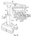
図1Bは、1つの実施形態による例示の遠隔操作アセンブリ100(例えば、図1Aに示される遠隔操作アセンブリ12)を示す。アセンブリ100は、突出するアーム(projecting arms)を支持する自動化され且つモータ駆動されるセットアップ構造を含み、床の上に置かれるベース102、ベース102に取り付けられる伸縮式支持コラム104、支持コラム104から延びる伸縮式ブーム105、及び配向プラットホーム107のようなプラットホーム部分を含み得る。アセンブリ100はまた、支持ビーム109、及び手術器具(画像キャプチャシステム18の部分を含む)を支持する幾つかのアーム106を含む。図1Bに示されるように、アーム106a、106b、106c、106dは、組織を操作するために使用される手術器具を支持し且つ動かす器具アームである。これらのアームの1つは、内視鏡を支持し且つ動かすカメラアームとして示され得る。 FIG. 1B illustrates an exemplary remote control assembly 100 (eg,
図1Eは、そこに取り付けられた交換可能な手術器具110を持つアーム106の1つを示す。手術器具は、カメラアームとして示されるアーム106に取り付けられる内視鏡であり得る。内視鏡は、手術部位の立体画像を取り込み且つ別個の立体画像をディスプレイシステム20に提供するための立体内視鏡であり得る。知識のある人は、器具及びカメラを支持するアームがまた天井若しくは壁、又はある例では、手術室の設備の他の部分(例えば、手術台)に(固定して又は移動可能に)取り付けられるベースプラットホームによって支持され得ることを認めるであろう。同様に、彼らは、2以上の別個のベースが使用され得る(例えば、1つのベースが各アームを支持する)ことを認めるであろう。 FIG. 1E shows one of the
図1Eにさらに示されるように、器具100は、器具インタフェース150及び器具シャフト150を含む。幾つかの実施形態では、遠隔操作アセンブリ100は、器具100をカニューレに対して固定するカニューレ用支持部を含み得る。幾つかの実施形態では、器具アーム106のそれぞれの部分は、患者に対して器具を位置決めするために手術室の人員によって調整可能であり得る。アーム106の他の部分は、(図1Cに示されるような)オペレータ入力システム120によって作動され且つ制御され得る。各アーム106に関連付けられる手術器具110はまた、オペレータ入力システム120のオペレータによって制御され得る。 As further shown in FIG. 1E, the
より詳細には、アーム106は、セットアップジョイント162を介して最遠位セットアップリンク164に接続される垂直セットアップ160を含む。ヨージョイント166が、最遠位セットアップリンク164を平行四辺形ピッチ機構168に接続する。平行四辺形ピッチ機構168は、それが動くことを可能にする複数のピッチジョイント170a、170b、170cを含む。スパー(spar)172が、スパージョイント174で平行四辺形ピッチ機構168に接続する。セットアップジョイント162、ヨージョイント166、ピッチジョイント170a、170b、170c、及びスパージョイント174のそれぞれは、ここでは、セットアップジョイントモータ、ヨージョイントモータ、ピッチジョイントモータ、及びスパージョイントモータと言及される、モータによって制御される。したがって、アーム106は、完全にモータ駆動される方法で動くように構成される。この実施形態では、モータは、制御システム22の制御下にあり、とりわけ、ドレーピング、患者への前進、手術器具へのドッキング、又は保管を支援し得る所望の姿勢を取るために他のアームのモータとともに操作され得る。加えて、各モータに関連付けられるエンコーダ及びセンサが、制御システムがアーム106の位置、状態、及びセットアップを検知又は検出するように、制御システム22にフィードバックを提供する。幾つかの実施形態では、スパー172は、アーム106上の手術ドレープの存在を検出するセンサを含む。 More specifically, the
遠隔操作アセンブリ100はまた、セットアップ及び動作を制御するためのユーザインタフェースとともに支持コラム104上にベースに対して固定されたヘルム(helm)111を含む。幾つかの実施形態では、ユーザインタフェースは、ユーザ入力を受け入れることができ且つグラフィックの、文字の、聴覚の、又は他のフィードバックを提供できる。タッチパッド154は、ドレーピング、ドッキング、又はそれがORの中で取るスペースをユーザが最小にするのを助けるためのしまい込みの準備のような遠隔操作アセンブリ100の動作のための機能を提供する。タッチパッド154はまた、システム障害通知及び回復のための手段を提供する。幾つかの実施形態では、タッチパッド154は、支持コラム104に沿って配置され且つ手術室のユーザによって見られるように構成される。他の実施形態では、タッチパッド又は他のユーザインタフェースが、別の場所に配置される。それは、有線式又は無線式であり得るとともに、バッグの中又は滅菌ユーザのために別の所に配置され得る。この実施形態のタッチパッド154は、遠隔操作アセンブリ100の状態に関連する情報データ、特定の手術に関する情報、及び遠隔操作医療システム10全体に関する情報を表示するように構成される。幾つかの実施形態では、タッチパッド154は、情報を提示し且つユーザ入力を受け入れるタッチパッドディスプレイインタフェースである。そうであるから、ユーザは、タッチパッドで、セットアップ指令を含む、制御指令を、入力し得る。 The
図1Cは、オペレータ入力システム120(例えば、図1Aに示されたオペレータ入力システム16)の正面図である。オペレータ入力システム120は、左及び右複数自由度(DOF)制御インタフェース122a及び122bを備えるコンソール122aを含み、この制御インタフェースは、内視鏡を含む手術器具110を制御するために使用される運動学的チェーンである。外科医は、典型的には親指及び人差し指で、制御インタフェース122のそれぞれの挟持体アセンブリ(pincher assembly)124a、124bを把持し、挟持体アセンブリを様々な位置及び向きに動かすことができる。ツール制御モードが選択されるとき、制御インタフェース122のそれぞれは、対応する手術器具及び器具アーム106を制御するように構成される。例えば、左制御インタフェース122aが、器具アーム106a及びその関連付けられる手術器具110を制御するように結合され得るとともに、右制御インタフェース122bが、器具アーム106b及びその関連付けられる手術器具110を制御するように結合され得る。第3の器具アーム106cが外科処置の間に使用され且つ左側に位置している場合、左制御インタフェース122aは、アーム106a及びその関連付けられる手術器具110を制御することからアーム106c及びその関連付けられる手術器具110を制御することに切り替えられることができる。同様に、第3の器具アーム106cが外科処置の間に使用され且つ右側に位置している場合、右制御インタフェース122bは、アーム106b及びその関連付けられる手術器具110を制御することからアーム106c及びその関連付けられる手術器具110を制御することに切り替えられることができる。幾つかの例では、制御インタフェース122a、122bと、アーム106a/手術器具の組合せと、アーム106b/手術器具の組合せとの間の制御の割り当ては、交換されてもよい。これは、例えば、内視鏡が180度回転される場合、内視鏡視野で動く器具が、外科医が動かしている制御インタフェースと同じ側にあるように見えるように、行われ得る。挟持体アセンブリは、典型的には、手術器具110の遠位端部のジョー式(jawed)手術エンドエフェクタ(例えば、鋏、把持開創器等)を操作するために使用される。 1C is a front view of operator input system 120 (eg,
追加の制御装置は、フットペダル128を備える。フットペダル128のそれぞれは、器具110の選択された1つの特定の機能を作動させることができる。例えば、フットペダル128は、ドリル又は焼灼ツールを作動させることができる又は洗浄、吸引、若しくは他の機能を動作させ得る。複数の器具が、ペダル128の複数のものを押すことによって作動されることができる。器具110の特定の機能は、他の制御装置によって作動されてもよい。 The additional controller comprises a
外科医用コンソール120はまた、立体画像ビューワシステム126(例えば、図1Aに示されるディスプレイシステム20)を含む。立体画像ビューワシステム126は、外科医が外科医の左目及び右目それぞれを使用して立体画像ビューワシステム126の中の左及び右立体画像を見ることができるように、左接眼レンズ125a及び右接眼レンズ125bを含む。内視鏡112によって取り込まれた左側及び右側画像は、対応する左及び右画像ディスプレイに出力され、外科医は、ディスプレイシステム(例えば、図1Aに示されたディスプレイシステム20)上で三次元画像を認識する。有利な構成では、制御インタフェース122は、ディスプレイに示される手術ツールの画像がディスプレイの下の外科医の手の近くに位置するように見えるように、立体画像ビューワシステム126の下に配置される。この特徴は、外科医が、あたかも手を直接見ているかのように、様々な手術器具を三次元ディスプレイの中で直観的に制御することを可能にする。したがって、関連付けられる器具アーム及び器具のサーボ制御は、内視鏡画像座標系に基づく。
内視鏡画像座標系はまた、制御インタフェース122がカメラ制御モードに切り替えられる場合に使用される。幾つかの場合には、カメラ制御モードが選択される場合、外科医は、制御インタフェース122の一方又は両方を一緒に動かすことによって内視鏡122の遠位端部を動かし得る。外科医はその後、あたかも画像を彼又は彼女の手に持つかのように、制御インタフェース122を動かすことによって表示された立体画像を直感的に動かし(例えば、パンする、チルトする、ズームする)得る。 The endoscopic image coordinate system is also used when the control interface 122 is switched to the camera control mode. In some cases, if the camera control mode is selected, the surgeon may move the distal end of endoscope 122 by moving one or both control interfaces 122 together. The surgeon may then intuitively move (eg, pan, tilt, zoom) the displayed stereoscopic image by moving the control interface 122 as if holding the image in his or her hand.
図1Cにさらに示されるように、ヘッドレスト130が、立体画像ビューワシステム126の上に配置されている。外科医が、立体画像ビューワシステム126を通して見ているとき、外科医の額はヘッドレスト130に対して位置決めされる。本開示の幾つかの実施形態では、内視鏡112又は他の手術器具の操作は、制御インタフェース122の利用の代わりにヘッドレスト130の操作を通じて達成されることができる。 As further shown in FIG. 1C, a
図1Dは、手術システムのビジョンカート構成要素140の正面図である。例えば、1つの実施形態では、ビジョンカート構成要素140は、図1Aに示された医療システム10の一部である。ビジョンカート140は、手術システムの中央電子データ処理ユニット142(例えば、図1Aに示される制御システム22の全て又は一部)及びビジョン装置144(例えば、図1Aに示される画像キャプチャシステム18の一部)を収容することができる。中央電子データ処理ユニット142は、手術システムを動作させるために使用されるデータ処理の多くを含む。しかし、様々な実装では、中央電子データ処理は、外科医コンソール120及び遠隔操作アセンブリ100に分散され得る。ビジョン装置144は、内視鏡112の左及び右画像取込機能のためのカメラ制御ユニットを含み得る。ビジョン装置144はまた、手術部位を撮像するために照明を提供する照明装置(例えば、キセノンランプ)を含み得る。図1Dに示されるように、ビジョンカート140は、オプションのタッチスクリーンモニタ146(例えば、24インチモニタ)を含み、これは、アセンブリ100の上又は患者側カートの上のような、その他の所に取り付けられてもよい。ビジョンカート140はさらに、電気手術ユニット、注入器(insufflators)、吸引洗浄器具(suction irrigation instruments)、又はサードパーティーの焼灼装置のようなオプションの補助手術装置のためのスペース148を含む。遠隔操作アセンブリ100及び外科医用コンソール120は、3つの構成要素が一緒に、外科医に直観的なテレプレゼンスを提供する単一の遠隔操作低侵襲手術システムとして機能を果たすように、例えば、光ファイバ通信リンクを介してビジョンカート140に結合される。 FIG. 1D is a front view of a
タッチスクリーンモニタ146は、本明細書に記載される誘導セットアッププロセス中に状態及びプロンプトを提供するユーザインタフェースを形成し得る。タッチスクリーンモニタが示されているが、タッチパッド154を参照して上述されたものを含む、他のタイプのユーザインタフェースが使用され得ることは特筆に値する。システムはセットアップステップがいつ完了するかを検知する又はその他の方法で認識するように構成されているので、幾つかの誘導セットアッププロセスは、ユーザインタフェースでユーザ入力を受信しないことは特筆に値する。したがって、幾つかの実施形態では、ユーザインタフェースは、ユーザ入力を受信しない単なるディスプレイである。手術システム10のさらなる詳細及び実施形態は、米国特許出願公開第2013/0325033号(2013年5月31日出願)及び米国特許出願公開第2013/0325031号(2013年5月31日出願)に記載され、これらの両方は、その全体が参照により本明細書に援用される。 Touch screen monitor 146 may form a user interface that provides status and prompts during the guided setup process described herein. Although a touch screen monitor is shown, it is worth noting that other types of user interfaces may be used, including those described above with reference to
幾つかの実施形態では、遠隔操作手術システムのアセンブリ100の幾つか又は全てが、仮想の(シミュレートされた)環境の中で実装されることができ、外科医用コンソール120で外科医によって見られる画像の幾つか又は全ては、器具及び/又は解剖学的構造の人工的な画像であることができる。幾つかの実施形態では、このような人工的な画像は、ビジョンカート構成要素140によって提供されることができる及び/又は外科医用コンソール120で(例えば、シミュレーションモジュールによって)直接的に生成されることができる。 In some embodiments, some or all of the
当然のことながら、図1A−1Eを参照して記載された遠隔操作手術システム10は、低侵襲手術処置を実行するより前にある程度のセットアップを必要とし得る。本明細書に記載される例示的な実施形態は、中央電子データ処理ユニット142によって実装される誘導セットアッププロセスの全て又は一部を用い得る。誘導セットアッププロセスは、機械により増大され(machine augmented)且つ構成に依存した(configuration dependent)誘導ウォークスルー(guided walkthrough)であり得る。それは、入力を動的に認識し得るとともに、様々なセットアップ動作を実行するためにユーザにガイダンス及びプロンプトを提供し得る。促された(prompted)セットアップ動作は、ユーザの先に選ばれた入力に基づくとともに、遠隔操作アセンブリ100の検知されたシステム構成に基づく。例えば、システムは、アーム106の位置を検知し得る、内視鏡のような器具が取り付けられているかどうかを検知し得る、アーム106がドレープされ且つ滅菌状態にあるかどうか、及び他の検知される構成を検知し得る。検知された遠隔操作アセンブリ構成を考慮するので、誘導ウォークスループロセスは、いつ各セットアップステップが自動化されたプロセスによって完了するか、いつ各セットアップステップが手動プロセスによって完了するか、いつユーザがセットアップステップを飛ばすつもりになっているか、及びいつセットアップステップが完了される必要がなく且つユーザに提示される必要がないかを認識し得る。したがって、誘導セットアップは、同様のタイプの手術の間でさえ異なり得る、安全で、さらに効率的なセットアッププロセスを維持するために、セットアッププロセスによってユーザを動的に誘導し得る。すなわち、誘導セットアップは、検知された遠隔操作アセンブリ構成並びにユーザが順序を外してセットアップステップを実行するときに生じるセットアップに基づいて、同様の手術の間で異なるセットアップ順序(シーケンス)を有し得る。そういうものとして、多くの柔軟なセットアップオプションが提示され得る。 Of course, the teleoperated surgical system 10 described with reference to FIGS. 1A-1E may require some setup prior to performing a minimally invasive surgical procedure. The example embodiments described herein may use all or part of the guided setup process implemented by the central electronic
遠隔操作アセンブリ100のタッチパッド154及びビジョンカート構成要素140のタッチスクリーンモニタ146に現れる視覚プロンプト、並びに聴覚指示により、誘導セットアップは、状況に応じた(context sensitive)段階的なガイダンスをユーザに提供する。誘導セットアップは、セットアップ動作の間、ユーザが効率的且つ効果的であるのを支援し得る。しかし、誘導セットアップの使用は、合理的なセットアップを達成するために必要とされず、必要に応じて単純に外科医によって無視され得る。例えば、ユーザは、彼らが選ぶ場合、異なる順番で自由にセットアップ動作を実行できる、又は彼らは、特定の臨床状況に適切であるかもしれないシステムに関する非標準的な構成を選択してよい。 With visual prompts that appear on the
セットアップは、ユーザが、遠隔操作アセンブリタッチパッド154の制御装置、並びにビジョンカートタッチスクリーン146と相互に作用することを含み得るので、関連するガイダンスが、遠隔操作アセンブリタッチパッド154及びビジョンカートタッチスクリーンモニタ146の両方に提供される。 Setup may involve the user interacting with the controls of the remote
誘導セットアッププロセスは、図2に記載されている、3つの一般的なセットアップ段階に分割され得る。これらの3つの特定された段階は、誘導セットアップシステムの説明を助けるために使用されているが、3つの特定された段階は重なり且つ幾つかの共通の特徴を共有するので、他の段階から必ず分割されるように扱われることが意図されるものではない。3つの一般的な段階は、ドレーピング段階202、ドッキング段階204、及びターゲティング(targeting)段階206である。 The guided setup process can be divided into three general setup stages, which are described in FIG. These three identified stages are used to help explain the guided setup system, but because they are overlapping and share some common features, they are always required from other stages. It is not intended to be treated as divided. The three general stages are a draping
図2の段階のそれぞれは、誘導セットアッププロセスの特定のステージを示す幾つかの状態を包含し得る。各状態は、ステップ又は遠隔操作アセンブリ100の特定の物理的な配置に関連付けられ得る。誘導セットアッププロセスは、ユーザを状態から状態にセットアッププロセスが完了するまで前進させる。特定の状態のためのステップ又は配置が満たされているとき、誘導セットアップは、次のセットアッププロセスステップを定める、次の状態に進み得る。 Each of the stages in FIG. 2 may include several states that represent particular stages of the induction setup process. Each state may be associated with a particular physical arrangement of steps or
中央電子データ処理ユニット142は、検知された遠隔操作アセンブリ構成を示す入力を受信するので、中央電子データ処理ユニット142は、いつ状態が完了するかを認識する。したがって、中央電子データ処理ユニット142は、ユーザによるユーザインタフェースでの入力なしに、誘導セットアップを次の状態に進め得る。加えて、ユーザは、遠隔操作アセンブリ100を誘導セットアッププロセスにおいてさらに進んだ状態に関連付けられる構成に単に設定することによって、誘導セットアップの1又は複数の状態又は状態の一部をオーバーライドし得る又は飛ばし得る。中央電子データ処理ユニット142は、次に、新しい構成を検知し、構成に対応する関連する状態を特定する。構成の状況は、システムが推測していることが状態及び次の必要な動作であること、を決定する。ユーザがシステムにおいて特に重要であると特定されている状態を飛ばしたように見えることをシステムが決定する場合、システムは、リマインダを出力する。しかし、ユーザが、リマインダを受信した後に続ける場合、システムは、検知された構成に基づいてユーザが次の状態に動かすことを続けさせ且つ許容する。 The central electronic
本明細書に記載される例示的な実施形態では、状態は、2つのユーザインタフェーススクリーン:遠隔操作アセンブリ100のタッチパッド154及びビジョンカート構成要素140のタッチスクリーンモニタ、に表示される、関連する指令及びプロンプトを含む。しかし、他の実施形態は、単一のユーザインタフェースを用いる一方、さらに他の実施形態は、さらに多くのユーザインタフェースを含む。図示された例示的な実施形態では、特定の状態に関連付けられる特定のプロンプトが、状態及び取られることになる次の動作に応じて、1つのインタフェーススクリーン又は他のものに示される。例えば、幾つかのプロンプトは、プロンプトが非滅菌野で実行され得る遠隔操作アセンブリ100のセットアップのための状態に関連するので、タッチパッド154のみに現れる。他のプロンプトは、プロンプトが滅菌野での注意を必要とする状態に関連するので、単にタッチスクリーンモニタ146に現れる。しかし、タッチスクリーンモニタ146及びタッチパッド154両方のプロンプトは、ユーザが図2の段階を通って協調された方法で進むように、協調され得る。幾つかの実施形態は、視覚プロンプトに加えて、可聴周波数の且つ音声のプロンプトを含む。幾つかの実施形態は、ユーザが、システムをサイレントモードに設定すること等、選択をカスタマイズすることを許容する。 In the exemplary embodiment described herein, the states are associated with instructions that are displayed on two user interface screens: the
図3は、タッチスクリーンモニタ146及びタッチパッド154両方のスクリーンプロンプトに関連付けられる一連の例示の状態を示す。状態に関連付けられるプロンプトは、ユーザが各段階(図2)を通って遠隔操作医療システム10の誘導セットアップを完了させるのを助ける。左の縦の列(column)は、遠隔操作アセンブリ100のタッチパッド154に表示され得るスクリーンプロンプトを有する幾つかの例示の状態を載せている。右の縦の列は、ビジョンカート構成要素140のタッチスクリーンモニタ146に表示され得るスクリーンプロンプトを有する幾つかの例示の状態を載せている。図3では、各状態に周りの線は、図2の段階の1つに対応する。例えば、点線の状態は、図2のドレーピング段階を形成する状態であり;実線の状態は、図2のドッキング段階を形成し;そして、破線の状態は、図2のターゲティング段階を形成する。ここでは、状態は、誘導セットアッププロセスの順序で示されている。しかし、誘導セットアップは、動的且つ適応可能であるとともに特定の順序に固守されないので、状態は飛ばされてよく、ことなって良く、他の状態が、図3に示されたものの1又は複数と置き換えられてよい。 FIG. 3 illustrates a series of exemplary states associated with screen prompts on both
依然として図3を参照すると、ドレーピング段階は、例えば、タッチパッド154上のドレーピングのために展開する状態252、タッチスクリーン146上のドレーピングのために展開する状態254、ドレーピング状態256、滅菌タスク状態258、及びアームバック状態266を含み得る。ドッキング段階は、例えば、解剖学的構造を選択する状態260、アプローチを選択する状態262、ドッキング状態を選択する状態268、ドッキングのために展開する状態270、及びスコープアームをドッキングする状態272を含み得る。ターゲティング段階は、患者にアプローチする状態274、手術が進行中の状態276、内視鏡を接続する状態278、ターゲティングする状態280、残りのアームを接続する状態282、及び手術が進行中の状態284を含み得る。 Still referring to FIG. 3, the draping stage may include, for example, a deploying
ドレーピングのために展開する状態252、254及びドッキングのために展開する状態270はそれぞれ、遠隔操作アセンブリ100のコラム104、ブーム105、アーム106、及び配向プラットホーム107の特定の姿勢に対応し得る。加えて、誘導セットアップルーチンの標準的な部分ではない、しまい込み状態もまた、遠隔操作アセンブリ100のコラム104、ブーム105、アーム106、及び配向プラットホーム107の特定の姿勢に対応し得る。しまい込み状態は、本質的に、遠隔操作アセンブリ100が、手術プロセスの任意の部分の前、手術プロセスの任意の部分の間、又は手術プロセスの任意の部分の後の期間に一時片づけられることになるときに使用され得る少なくとも部分的にコンパクトである停止状態である。 The deployed states 252, 254 for draping and the deployed
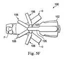
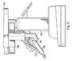
図4、5A−5F、及び6は、異なる予め確立された姿勢に関連する異なる位置又は姿勢の例を示している。例えば、図4は、ドレーピング位置の遠隔操作アセンブリ100を示し;図5A−5Fは、様々なドッキング位置の遠隔操作アセンブリ100を示し;そして図6は、しまい込み位置の遠隔操作アセンブリ100を示している。 4, 5A-5F, and 6 show examples of different positions or poses associated with different pre-established poses. For example, FIG. 4 illustrates
図示された実施形態では、遠隔操作アセンブリ100のタッチパッド154は、コラム104、ブーム105、アーム106、及び配向プラットホーム107を予め確立された位置に展開させるための指令を入力するために使用され得る。他の入力装置もまた、指令を入力するための使用のために考えらえる。したがって、幾つかの実施形態では、タッチパッド154は、とりわけ、ドレーピングのために展開するボタン、しまい込みボタン、及びドッキングのために展開するボタンを含む。 In the illustrated embodiment, the
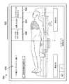
図4のドレーピングのために展開する位置は、コラム104を通る面を基準に記載される。図4を参照すると、図面に平行な面は、コロナル(coronal)面180と見なされ、コロナル面にまさに直交する面は、サジタル(sagittal)面182である。遠隔操作アセンブリ100の前部は、サジタル面182の方向に面し、コロナル面は、遠隔操作アセンブリの側部に直接延びる。 The unfolded position for draping in FIG. 4 is described with reference to the plane passing through the
図4は、ドレーピングのために展開する位置の遠隔操作アセンブリ100を示している。ドレーピングのために展開する位置は、アーム106及び/又はコラム104がドレープされることになるとき、遠隔操作アセンブリによって自動的に取られる姿勢である。本明細書で使用されるとき、自動的に取られる姿勢は、単一の瞬間的な入力によって又は継続的に押されるボタンのような継続的な入力を通じて達成される運動を含む。継続的な入力の実施形態では、遠隔操作アセンブリは、ボタンが押されている間のみ動き、ボタンがもはや押されていないとき全ての運動を停止させる。これは、安全上の又はその他の理由で必要なときユーザが即座に運動を停止させることを可能にする。幾つかの実施形態では、ドレーピングのために展開する位置は、ユーザが、ドレーピングのために展開するボタンを選択することによってのように、ドレーピングのために展開する位置を取るための指令を入力するときのみ取られる。 FIG. 4 shows the
この例示的な実施形態に見ることができるように、コラム104は、アームが、平均の高さの人によってアクセスされるのに便利な高さにあるように延びる。幾つかの実施形態では、スパー172は、それらの上端部が、約54インチから66インチの範囲の高さになるように、配置される。しかし、他の高さも考えられる。垂直セットアップ160は、配向プラットホーム107によって担持される支持ビーム109から部分的に延ばされる。アーム106は、垂直セットアップ160、最遠位セットアップリンク164、平行四辺形ピッチ機構168、及びスパー172を含むアーム106のそれぞれの要素が、滅菌ドレープで個別にドレープされ得るように、サジタル面の方向にそれぞれ部分的に延びる。ドレーピングのために展開する姿勢は、ドレーピングより前に十分なアーム間の間隔のためにスパー172を位置決めする。間隔は、折り畳まれたドレープがアームの上に置かれること及びアーム制御モードを始動させるための滅菌バリアとして使用されることを可能にするので、滅菌されたユーザが手術室の利用可能なスペースにアームをさらに延ばし得る。この実施形態では、スパー172は、隣接するスパーからスパーの上部において僅かに大きく且つスパーの底部においてわずかに小さく間隔を置かれるように姿勢にされる。したがって、最も外側のスパー172は、サジタル面182に対して最も角度を付けられる。これは、スパー172の上部の上に置かれ得る追加のドレープ材料を収容する。加えて、各スパー172は、ユーザがより簡単にドレープをスパー172に接続し得るように、スパー172の上部がスパーの底部よりコロナル面からさらに間隔を空けられる状態でサジタル面方向に角度を付けられる。幾つかの実施形態では、ドレープが、アーム106上のドレープの存在を認識するスパー172上のドレープセンサ(drapery sensor)を作動させるように適切に配置されることができるように、ユーザは、スパー172の上部を見ることができてよい。図4のドレーピング位置のアーム106は、ユーザが、側部に延びるアーム106a及び106dにアクセスする替わりに、全てのアーム106に前部からアクセスできるように、概して前方又はサジタル方向に面する。図4に示される例示のドレーピング位置は、遠隔操作アセンブリ100が、アクセスのための無制限のスペースを有さない手術室内でドレープされる場合に適応するために部分的にコンパクトである。加えて、互いに隣接するアームの付近は、アームを効率的なドレーピングのために互いに十分近くにしながら、ドレーピングのための十分なスペースを提供する。 As can be seen in this exemplary embodiment, the
例示的な態様では、ドレーピングプロセスのための展開が開始されるとき、遠隔操作医療システム10に関する複数の制御システムを含み得る、中央電子データ処理ユニット142は、アーム106をドレーピング位置に配置するためにアーム106を制御する。ドレーピング位置は、遠隔操作アセンブリ100の一連の連続的な運動によって得られ得る。例えば、連続的な運動は、ブーム運動、アーム展開運動、及び垂直セットアップジョイント運動を含み得る。ブーム運動は、ドレーピングの便宜のためにブームを予め設定された高さに持ち上げることを含み得る。アーム展開運動は、次に、追加の入力なしに続き得る又は、例えば、ボタンでの継続的な入力の結果として自動的に続き得る。アーム展開運動は、アーム106を延ばすこと及び上述の方法でスパー172を配置することを含み得る。垂直セットアップジョイント運動は、アーム展開運動の後に続くとともに、上述の方法で垂直セットアップジョイント164を調整することを含む。 In an exemplary aspect, the central electronic
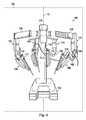
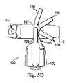
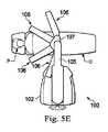
図5は、ドッキング位置の遠隔操作アセンブリ100を示す。ドッキング位置は、ユーザが、治療されることになる概略の解剖学的構造領域及び患者へのアプローチ(例えば、患者の左又は右側)を選択したとき取られる姿勢である。ドッキング位置の遠隔操作アセンブリ100で、それは患者の上で動かされることができる。この駆動位置では、アームは僅かに引っ込められ、スパーはカニューレとのドッキングに備えて直立して向けられ、コラム104はブーム105及びアーム106を患者台より上に高く持ち上げるように延ばされる。加えて、垂直セットアップ160は、遠隔操作アセンブリが患者の上で進められるときアーム106が患者を妨げのない十分な高さになるように、持上げられる。ドッキングプロセスのための展開はまた、治療されることになる選択された解剖学的構造領域のために、遠位セットアップジョイント162を調整する。このジョイントは、手術のための最適な設定に近づく間のロールアップ(rollup)に際し適切な間隔を提供するように、解剖学的構造及びアプローチ方向に基づいて知的に設定される。例えば、患者の上を通り過ぎる必要のない外側アーム106は、最大の器具の届く範囲のために低く展開されることができる一方、患者の上を通り過ぎなければならない外側アームは、ロールアップに際して適切な患者との間隔を確保するために中間の高さに展開され得る。同時に、治療されることになる選択された解剖学的構造領域及び選択されたアプローチに応じて、配向プラットホーム107及び支持ビーム109も制御され得る。幾つかの実施形態では、1又は複数のジョイントは、受動的に制御され且つ非モータ駆動であり得る一方、他の実施形態では、全てのジョイントは、モータ駆動され且つ誘導セットアップの目的のために制御される。 FIG. 5 shows the
例示の態様では、ドッキングプロセスのための展開が開始されるとき、遠隔操作医療システム10に関する複数の制御システムを含み得る、中央電子データ処理ユニット142は、アーム106をドッキング位置に配置するためにアーム106を制御する。ドッキング位置は、治療されることになる概略の解剖学的構造領域及び患者へのアプローチに依存し得る。幾つかの態様では、ドッキングプロセスのための展開は、ドッキング姿勢を得るための一連の連続的な運動を含む。例えば、連続的な運動は、アーム展開運動、垂直セットアップジョイント運動、ブーム運動、プラットホーム運動、及びアーム再展開運動を含み得る。 In an exemplary aspect, the central electronic
アーム展開運動は、アームが、比較的垂直な位置のスパー172とともに、比較的コンパクトであるような構成にアームを押し込む(tuck)ことを含む。上で示されたように、アプローチ(例えば、患者の右側、患者の左側、又は患者の脚部アプローチかどうか)に応じて、アームの高さは、間隔(clearance)対届く範囲(reach)のトレードオフに対するアームごとの基準で最適化されるセットアップジョイント角度を伴って、最大の高さに設定される。例えば、患者の上を通り過ぎないアームの高さは、最大の器具の届く範囲のために低く展開され、患者の上を通り過ぎなければならないアームの高さは、ロールアップに際し適切な患者間隔を確保しながら、十分な届く範囲を提供するように中間の間隔で展開される。 The arm unfolding movement involves tucking the arm into a configuration that is relatively compact with the
アームが動くことを終了するとき、垂直セットアップジョイント運動が、別個の入力なしに生じる。例えば、継続的な入力の実施形態では、同じ継続的な入力に基づいて、遠隔操作アセンブリは、垂直セットアップジョイント運動を始める。この運動では、垂直セットアップジョイント160は、アームのための間隔を提供するためにアームの近位部分をそれらの最高の高さに持ち上げるように完全に引っ込められる。垂直セットアップジョイント運動が完了するとき、システムは、追加の入力なしにブーム運動を実行する。すなわち、継続的な入力のような、同じ入力を使用して、システムはブームを操作する。ブーム運動は、伸縮式コラム104によりブームを持ち上げることを含み得る。プラットホーム運動は、ブーム運動の後に続き、プラットホームを目標の向き(target orientation)に回転させることを含む。これは、選択されたアプローチに基づき、異なるプラットホーム運動が図5B−5Fに示されている。プラットホーム運動の後、アーム106は、患者に関連付けられるカニューレへのドッキングのための便利な位置に再展開される。これは、スパー172を直立位置に配置すること及び最遠位セットアップリンク164を、選択されたアプローチ及び解剖学的構造領域に関連付けられる予め設定された状態に向けることを含み得る。 When the arm finishes moving, a vertical setup joint motion occurs without a separate input. For example, in the continuous input embodiment, the remote control assembly initiates a vertical setup joint movement based on the same continuous input. In this movement, the vertical setup joint 160 is fully retracted to raise the proximal portions of the arms to their maximum height to provide clearance for the arms. When the vertical setup joint movement is complete, the system performs a boom movement without additional input. That is, the system operates the boom using the same input, such as continuous input. The boom movement may include lifting the boom with the
幾つかの実施形態は、ユーザが、任意の選択された解剖学的構造領域及びアプローチの組合せに関連付けられるデフォルト(default)高さより大きい高さにブームを持ち上げることを許容する。この調整された高さは、その後、展開シーケンスの残りのもののためのフロア(floor)として使用され得る。したがって、患者が典型的な患者より大きいとき又は患者が典型的な患者より高いとき、システムは、単純な高さの調節によって展開プロセスにおける全ての運動を補償し得る。 Some embodiments allow the user to lift the boom to a height greater than the default height associated with any selected anatomical region and approach combination. This adjusted height can then be used as the floor for the rest of the deployment sequence. Thus, when the patient is larger than the typical patient or when the patient is higher than the typical patient, the system can compensate for all movements in the deployment process by simple height adjustments.
図5B−5Fは、ユーザの入力に基づいて取られ得る異なるドッキング位置を示す。例えば、図5Bは、遠隔操作アセンブリが患者の左側からアプローチしているアプローチを示し、治療部位は患者の下方の解剖学的構造領域にあり得る。図5Cは、遠隔操作アセンブリが患者の左側からアプローチしているアプローチを示し、治療部位は患者の上方の解剖学的構造領域にあり得る。図5Dは、遠隔操作アセンブリが患者の右側からアプローチしているアプローチを示し、治療部位は患者の下方の解剖学的構造領域にあり得る。図5Eは、遠隔操作アセンブリが患者の右側からアプローチしているアプローチを示し、治療部位は患者の上方の解剖学的構造領域にあり得る。図5Fは、遠隔操作アセンブリが患者の脚部からアプローチしているアプローチを示し、治療部位は患者の下方の解剖学的構造領域にあり得る。 5B-5F show different docking positions that may be taken based on user input. For example, FIG. 5B shows the approach where the remote control assembly is approaching from the left side of the patient, where the treatment site may be in the lower anatomical region of the patient. FIG. 5C shows the approach where the remote control assembly is approaching from the left side of the patient, and the treatment site may be in the upper anatomical region of the patient. FIG. 5D shows the approach where the remote control assembly is approaching from the right side of the patient, where the treatment site may be in the lower anatomical region of the patient. FIG. 5E shows the approach where the remote control assembly is approaching from the right side of the patient, where the treatment site may be in the upper anatomical region of the patient. FIG. 5F shows the approach where the remote control assembly is approaching from the patient's leg, where the treatment site may be in the lower anatomical region of the patient.
図6は、しまい込まれた位置の遠隔操作アセンブリ100を示す。コンパクトなしまい込まれた位置は、手術室で遠隔操作アセンブリによって占められるスペースを最小にする。したがって、この位置では、全てのアーム106は、コラム104に対してきつく密集され、ブーム105は、アーム106を収容しながらできる限り引っ込められ、コラム104は、遠隔操作アセンブリを出来る限り小さくするように完全に短縮される。ここでは、配向プラットホームは、支持ビーム109が最小のフットプリントを有するように、支持ビーム109が配向プラットホームから後方方向に延びることを可能にするように回転される。 FIG. 6 shows the
例示の態様では、しまい込みプロセスが開始されるとき、遠隔操作医療システム10に関する複数の制御システムを含み得る、中央電子データ処理ユニット142は、遠隔操作アセンブリ100をしまい込み位置に配置する。これは、上述のように、継続的な入力を通じて行われ得る、又は単一の瞬間的な入力を通じて起こり得る。幾つかの態様では、しまい込み位置は、一連の連続的な運動により達成される。例えば、連続的な運動は、プラットホーム運動、垂直セットアップジョイント運動、アーム引っ込め運動、及びブーム運動を含み得る。 In the illustrated aspect, the central electronic
プラットホーム運動は、真っ直ぐに面する位置(straight forward facing position)にプラットホームを回転させることを含む。垂直セットアップジョイント運動は、アームをブームの近くに動かすために垂直セットアップジョイントを持ち上げる。アーム引っ込め運動は次に、アームが、コラム104の各側部に2つのアームを伴って、横方向に一緒に詰め込まれるように、アーム106を引っ込める。ブーム運動は次に、手術室で小さく、コンパクトなフットプリントを作るように、ブームをコンパクト位置に完全に下げる。好適な実施形態では、アーム106は、ベース102のフットプリントの中に納まるようにある配置に位置決めされる。 Platform movement involves rotating the platform into a straight forward facing position. The vertical setup joint movement lifts the vertical setup joint to move the arm closer to the boom. The arm retracting motion then retracts
幾つかの実施形態は、千鳥配置(staggered arrangement)をもたらし、これは、コラムの前に配置されているアーム106bのような第2のアーム、隣接する、曲げられ且つすぐ近くに配置されるアーム106aのような第1のアーム、後ろにずっと押され且つコラム104の右側に対して押されたアーム106cのような第3のアーム、及び、第3のアーム近くに曲げられ且つ内側に回転されたアーム106dのような第4のアームを含む。 Some embodiments provide a staggered arrangement, which includes a second arm, such as
幾つかの実施形態は、別の滅菌しまい込み位置を含む。この位置は、フットプリントを最小にする位置でもあるが、コラム104及びアーム106を、それらが滅菌ドレープで覆われている間に収容することが意図されている。この位置では、アーム106は、手術室でのそれらの目障りさを最小にするが依然として滅菌ドレープを清潔且つ損傷を受けていない状態に保つ方法でまとめられる。滅菌しまい込み位置は、したがって、遠隔操作システム10が、アーム106及び/又はコラム104が滅菌ドレープで覆われていることを検出するときのしまい込み位置であり得る。 Some embodiments include another sterile stowage location. This position, which is also the position that minimizes the footprint, is intended to accommodate the
幾つかの実施形態では、中央電子データ処理ユニット142は、コラム104、ブーム105、アーム106、及び配向プラットホーム107の運動を、それぞれに関連付けられるモータを、それらを所望の位置に動かすように制御することによって、制御する。幾つかの実施形態では、遠隔操作アセンブリ100は、遠隔操作アセンブリ100が(例えば、輸送に備えて)スタンドアローンで使用されるときでさえ、ドレーピングのための展開、ドッキングのための展開、及びしまい込み機能が、実行できるように、それ自身のスーパバイザ(supervisor)及びコントローラを含む。タッチパッド154のような、ユーザインタフェースで起動された指令に応じて、中央電子データ処理ユニット142のスーパバイザロジックが、コラム104、ブーム105、アーム106、及び配向プラットホーム107を所望の姿勢に動かすように、制御信号を出力する。幾つかの態様では、中央電子データ処理ユニット142は、アーム及びセットアップジョイントのコラムとの衝突を積極的に回避する方法でアームの動きを順序付ける又はその他の方法で協調させるためのアルゴリズムを含む。幾つかの態様では、中央電子データ処理ユニット142は、例えば、手術台のような、物体との衝突を緩和するための自動化された動きの間に、ジョイント運動を監視する。以下に説明されるように、予め確立された姿勢は、誘導セットアップシステムの異なる段階又は状態と関連付けられ得る。 In some embodiments, the central electronic
図7A−7Cは、遠隔操作医療システム10によって実行される誘導セットアップを使用する例示の方法を示す。図7の方法は、図2のドレーピング段階202において誘導セットアップのプロンプトを表示することによって始まり、次に、ドッキング段階204に進み、最終的にターゲティング段階206を通過する。幾つかの例示の実施形態では、タッチパッド154は、プロセスを起動する選択可能な誘導セットアップ機能ボタンを含む。したがって、ユーザが誘導セットアップを選択又は起動した後、システムは、ドレーピング段階における様々なステップを完了させることをユーザに促す。 7A-7C illustrate an exemplary method of using a guided setup performed by the telemedicine medical system 10. The method of FIG. 7 begins by displaying a prompt for guidance setup in the
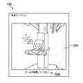
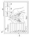
方法は、タッチパッド154及びタッチスクリーンモニタ146の両方にドレーピングのために展開するプロンプトを表示することによって、ドレーピングのために展開する状態252、254の302において始まる。図8は、ホームタブが選択されたタッチパッド154の例示の誘導セットアップユーザインタフェースを示す。ユーザインタフェース220は、示される例で、複数の選択可能ボタン522、誘導セットアップスクリーンプロンプト524、及び解剖学的構造を選択する展開可能なメニュー526を含む。この実施形態の選択可能ボタン522は、「ドレーピングのために展開する」ボタン528、「しまい込み」ボタン530、及び「ジョイスティックを有効にする」ボタン532を含む。図9は、タッチスクリーンモニタ146上の例示の誘導セットアップユーザインタフェースを示す。見ることができるように、それは、ユーザに、誘導セットアップを起動するとともにドレーピングのために遠隔操作アセンブリ100(図1B)を展開させるために、遠隔操作アセンブリ100のタッチパッド154を参照させる。タッチスクリーンモニタ146は、説明的な画像534及び文字プロンプト536を含む。タッチスクリーンモニタ146はまた、他の機能を実行し得る又は静止状態にあり得る。幾つかの実施形態では、タッチスクリーンモニタ146及びタッチパッド154の両方は、同様の状態にあり得るとともに、同様のプロンプトを表示し得る。 The method begins in deploying
図8を参照すると、ユーザは、図4に示されたドレーピングのために展開する構成で、コラム104、ブーム105、アーム106、及び配向プラットホーム107を展開させる自動的なプロセスを起動するために、ドレーピングのために展開するボタン528を押すオプションを有する。幾つかの実施形態では、コラム104、ブーム105、アーム106、及び配向プラットホーム107は、ボタン528がタッチパッド154上で押されている又はタッチされている間のみ動く。これは、指をボタン528から単に離すことによって、コラム104、ブーム105、アーム106、及び配向プラットホーム107の運動をユーザが停止させることを可能にし得る。ボタンが押されるとき、中央電子データ処理ユニット142は、上で説明されたアーム衝突又は接触も回避する遠隔操作アセンブリ100への指令信号を生成し且つ送信する。 Referring to FIG. 8, the user may initiate an automatic process to deploy the
ユーザはまた、しまい込みボタン530を選択するオプションを有する。これは、図6に示されるしまい込み位置に遠隔操作アセンブリ100を自動的に展開させる。この場合もまた、運動は、ボタン530がタッチパッド154上で押されている又はタッチされている間のみ生じ得る。 The user also has the option of selecting the
好適な実施形態では、遠隔操作システム10は、滅菌ドレープが、支持コラム104、ブーム105、及びアーム106のいずれかに適切に設置されている場合をセンサ又はスイッチにより認識するように構成される。それはまた、センサ、エンコーダ、又は他の装置により、支持コラム104、ブーム105、及びアーム106の位置を認識するように構成される。 In the preferred embodiment, the remote control system 10 is configured to detect by a sensor or switch when the sterile drape is properly installed on either the
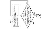
図7Aの304において、中央電子データ処理ユニット142は、アーム106のいずれかがドレープされているかどうか、支持コラム104がドレープされているかどうか、遠隔操作アセンブリ100がドレーピングのために展開されているかどうか(図4に示されたドレーピングのために展開された位置にあることを意味する)、又はアーム106が動作不能にされているかどうかを質問する。304において記載された条件のいずれにも当てはまらない場合、システムスクリーンに変化は無く、タッチパッド154及びタッチスクリーンモニタ146は、ドレーピングのために展開する状態252、254に維持される。このようなものとして、タッチパッド154は、図8の524において「ドレーピングのために展開する」プロンプトを表示し続ける。しかし、条件のいずれかが当てはまる場合、誘導セットアップシステムは、セットアッププロセスを進ませる特定のユーザ入力を受信することなしに次のセットアップ状態に自動的に進むことができる。 At 304 in FIG. 7A, the central electronic
上述のように、誘導セットアップは、ユーザにセットアップガイダンスを動的に提供するが、必要に応じてガイダンスに従うことなしにユーザがシステムをセットアップすることも許容する。この実施形態では、ユーザは、「ドレーピングのために展開する」ボタンを使用してドレーピングに適する位置にアーム106を配置し得る、又は代替的に、アームの位置にかかわらずドレーピングプロセスを手動で始め得る。したがって、例えば、ユーザが、オペレータ入力システム120(図1C)を使用してアームを制御するとしたら又はアームをドレーピングに適する位置に配置するために手動でアームを把持して変位させるとしたら、誘導セットアップシステムは依然として、制御システムがアーム又はコラムの一方がドレープされていることを検出する場合に、次の状態に進む。したがって、システムは、ユーザがドレーピングのために展開する状態254を超えて動かしたこと、及びドレーピング状態256で作業していることを認識する。したがって、アーム106は、タスクが適切に完了され得ることを認識するために、及びドレーピングのために展開する状態から次の状態に進むために、自動的な展開設定により達成される最適位置にある必要はない。 As mentioned above, guided setup dynamically provides the user with setup guidance, but also allows the user to set up the system as needed without following the guidance. In this embodiment, the user may use the "deploy for draping" button to place
304における基準が満たされるとき、中央電子データ処理ユニット142は、タッチスクリーンモニタ146をドレーピングのために展開する状態254からドレーピング状態256に進ませるようにタッチスクリーンモニタ146を制御し、図7Bに示されるように、306において、「アーム及びコラムをドレープする」を表示する。タッチスクリーンモニタ146は、ユーザが、遠隔操作アセンブリ100の前に立ちながら又は遠隔操作アセンブリ100で作業しながら、タッチスクリーンモニタ146を見ることができるように、ビジョンカート構成要素140に配置されているので、アーム及びコラムをドレープするプロンプトは、タッチスクリーンモニタ146に表示され得る。 When the criteria at 304 are met, the central electronic
図7Bの308において、タッチスクリーンモニタ146がドレーピング状態256に進むとき、タッチパッド154は、図3のドッキング段階204を始める。ここでは、それは、ドレーピングのために展開する状態252を離れ、解剖学的構造を選択する状態260に入り、誘導セットアップスクリーンプロンプト524において解剖学的構造を選択するプロンプトを表示する。この例が図10に示されている。加えて、図8の解剖学的構造を選択するボタン526は、手術が起こり得る複数の選択可能な体の領域のメニュー533を示すためのユーザ入力なしに自動的に展開又は開く。ユーザは、タッチパッド154上のメニュー533から選択することによって、解剖学的構造領域を入力し得る。 At 308 of FIG. 7B, when the touch screen monitor 146 proceeds to the draping
図7Bの310において、体の領域が選択された後、タッチパッド154は、アプローチを選択する状態262に進み、誘導セットアップスクリーンプロンプト524としてアプローチを選択するプロンプトを表示する。この例が図11に示されている。選択された解剖学的構造領域に応じて、幾つかの可能なアプローチが選択のために提示される。図11では、可能な選択可能なアプローチは、患者の左ボタン540又は患者の右ボタン542である。図11は、胸部の体の領域がステップ308において選択された場合、選択可能なアプローチが、患者の右及び患者の左に限られ得ることを示している。他の解剖学的構造領域が追加のアプローチを使用して治療され得ることは特筆に値する。例えば、骨盤領域が308において選択される場合、選択可能なアプローチは、患者の右、患者の左、及び患者の脚部を含み得る。ユーザは、アプローチを、タッチパッド154上で選択することによって入力し得る。 After the body region has been selected at 310 in FIG. 7B, the
図11ではまた、しまい込みボタン530(図10)が、滅菌しまい込みボタン544に変更されており、ドレーピングのために展開するボタンは、ドッキングのために展開するボタン546に変更されている。幾つかの実施形態では、この変更は、1又は複数のドレープの設置の結果として生じる。滅菌しまい込みは、手術ドレープがコラム104又はアーム106に配置された後に選択され得る。滅菌しまい込みは、ドレープが損傷を受けず且つ滅菌の状態に維持しながら、遠隔操作アセンブリ100の全体のフットプリントを減少させるように意図されたしまい込みである。したがって、滅菌しまい込み位置は、図6に示されるしまい込み位置より、コンパクトでない可能性がある。本明細書で論じられる他の自動的な位置と同様に、幾つかの実施形態は、コラム104、ブーム105、アーム106、及び配向プラットホーム107が、ボタン530がタッチパッド154上で押されている又はタッチされている間のみ動くことを可能にし得る。他の実施形態は、ボタンに圧力を維持することなしに単にボタンを押した後に、予め設定された位置まで完全に動かすように、コラム104、ブーム105、アーム106、及び配向プラットホーム107を制御する。 In FIG. 11 again, the stowage button 530 (FIG. 10) has been changed to a
図7Bのステップ312において、ユーザが解剖学的構造及びアプローチを選択した後、中央電子データ処理ユニット142は、アーム106及びコラム104がドレープされ且つコンパクトな位置にあるかどうかを質問し得る。すなわち、誘導セットアップシステムは、ドレーピングが完了したかどうかを質問し得る。そうでない場合、システムは、314において待つ。ここでは、タッチパッド154は、滅菌タスク状態258に進み、誘導セットアップスクリーンプロンプト524において滅菌タスクを待っているプロンプトを表示する。アプローチが310において選択されるときにアーム又はコラムが既にドレープされ且つコンパクトな位置にある場合、又はアーム又はコラムが314においてドレープされているとき、タッチスクリーン154は、ドッキングのために展開する状態264に進む。この状態では、図7Bの316において、タッチスクリーン154は、スクリーンプロンプト524としてドッキングのために展開するプロンプトを表示する。これは、以下にさらに論じられる。 In
上で論じられたように、誘導セットアップシステムは、必要とされない又は既に完了されているかもしれない状態をバイパスするように構成される。したがって、312において、システムが、アーム及びコラムが既にドレープされていること及びアームがコンパクトな位置にあることを検知する場合、誘導セットアップは、遠隔操作システム10における実際のユーザ入力なしに、滅菌タスク状態258を飛ばすとともに316においてドッキングのために展開する状態に直接進む。すなわち、システムは、アーム及びコラムがそれらの上に滅菌ドレープを有することを検出し、アームの位置を検出する。したがって、ユーザインタフェースにおける追加の入力なしに、システムは、滅菌タスク状態258をバイパス又は飛ばし、ドッキングのために展開する状態に移動する。 As discussed above, the guidance setup system is configured to bypass states that may not be needed or may have already been completed. Thus, at 312, if the system detects that the arm and column are already draped and that the arm is in a compact position, the guidance set-up will proceed without sterilization tasks without actual user input at the remote control system 10. Skip
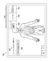
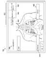
上述のように、特定の動作が、タッチパッド154及びタッチスクリーンモニタ146上で同時に発生し得る。したがって、図7Bの306において、タッチスクリーンモニタ146は、ドレーピング状態256で動作するとともに、コラム及びアームをドレープするプロンプトを表示する。遠隔操作医療システム10は、ビジョンカートタッチスクリーンモニタ146においてユーザにフィードバックを提供し、どのアームがドレープされているかを示す。例示的なフィードバックは、例えば、各アームの画像及びそれが適切にドレープされているかどうかのインジケータを含み得る。このインジケータは、色、陰影、数、又は他のインジケータのような、識別マーカーであり得る。したがって、遠隔操作アセンブリ100は、ドレープがアーム上に適切に設置されているかどうかを検知し得るとともにこれをユーザに提示し得る。図12は、タッチスクリーンモニタ146上に表示され得るときの各アーム及びコラムの画像を示す。遠隔操作システム10は、アーム又はコラムがユーザインタフェースにおけるプロンプトなしでドレープされているかどうかを検知し且つ決定するように構成される。タッチスクリーンモニタ146上の誘導セットアッププロンプト536は、ドレープを設置するために作業する滅菌ユーザによって見られ得る。各ドレープが設置されるとき、アームは、アームがセットアッププロセスの次のステップのために準備されていることを示すように、ハイライトされ得る又は他の方法でマークされ得る。この実施形態では、アーム1及び2がハイライトされて示され、したがって、適切にドレープされているとして示されている。 As mentioned above, certain actions may occur simultaneously on
318において、中央電子データ処理ユニット142は、アーム及びコラムが適切にドレープされているかどうかを決定する。そうでない場合、タッチスクリーンモニタ146は、図12に示される誘導セットアップスクリーンを表示し続ける。 At 318, central electronic
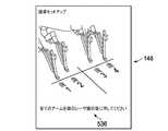
318において、システムが、アーム及びコラムが適切にドレープされていることを検知する場合、タッチスクリーンモニタ146は、アームバック状態266に進み、ドレーピング段階202の一部を形成する。それに応じて、誘導セットアップは、320に進み、320において自動的に基準レーザ線をオンにするとともにユーザに基準レーザ線の後に全てのアームを押すように命じる。このスクリーンの例は図13に示されている。幾つかの実施形態では、ユーザの注意がアームにあり、タッチパッド154又はタッチスクリーンモニタ146に無いかもしれないので、システムは、音声プロンプトを発生させる。したがって、システムは、例えば「全てのアームを緑のレーザ線の後に押してください」のような、音声プロンプトを提供し得る。この位置は、ユーザが、遠隔操作アセンブリ100を患者に後に進ませることを可能にする。図13のスクリーンショットは、実際のレーザ基準線に対応する基準線に対する個々のアームを示している。実際のアーム106が実際の基準レーザ線の後に物理的に動くにつれて、図13の画像中のアームも表示された線に対して後方に変位する。かくして、ユーザは、どのアームが十分に引っ込められているか及びどれがそうでないかを正確に知る。これは、システムが、ワークフロー全体の効率を促進させるためのリマインダを使用する例である。滅菌ユーザは既にアーム106の近くにいるので、そのユーザは、アーム106がレーザを遮っていないことを確実にするのによく適している。レーザは、遠隔操作アセンブリ100を患者に駆動するとき、非滅菌ユーザによって後に使用される。アーム106がレーザを遮る位置にされる場合、後続の駆動タスクは、遅延させられ得る又は遠隔操作アセンブリ100の準最適な位置決めをもたらし得る。 At 318, if the system detects that the arms and columns are properly draped, the
図7Bの322において、中央電子データ処理ユニット142は、アームが基準レーザ線の後に適切に配置されているかどうかを質問する。そうでない場合、タッチスクリーンモニタ146は、320においてユーザにプロンプトし続ける。 At 322 in FIG. 7B, central electronic
全てのアームが、322においてレーザ基準線の後ろにあるとき、中央電子データ処理ユニット142は、解剖学的構造領域及びアプローチがタッチパッド154上で既に選択されたか(上の308及び310を参照して論じられた)どうかを質問する。324において、解剖学的構造領域及びアプローチが、以前に選択されていない場合、タッチスクリーンモニタ146は、図7Bのステップ308及び310を実行するためにユーザをタッチパッド154に誘導するように325においてリマインダ又はプロンプトを表示し得る。すなわち、タッチスクリーンモニタ146は、図3のドッキングを選択する状態268に進み得るとともにユーザに解剖学的構造領域及びアプローチを入力するように指示し得る。 When all arms are behind the laser reference line at 322, the central electronic
解剖学的構造領域及びアプローチが図7Bの324において既に選択された場合、誘導セットアップシステムは、ドッキングを選択する状態268を完全にバイパスし、誘導セットアップは直接326に進み得る。 If the anatomical region and approach were already selected at 324 in FIG. 7B, the guided setup system may completely bypass docking selected
326において、中央電子データ処理ユニット142は、アームが基準線の後にバックしていることを再び確認する。アームが326においてバックしていない場合、システムは、320のアームを押し戻すプロンプトに戻る。アームがバックしている場合、システムは、328においてアームがドレープされていることを再び確認する。アームがドレープされていない場合、システムは、アーム及びコラムをドレープするプロンプトを表示する306に戻る。実際、制御システム全体の一部として動いている2つの別々の状態機械があることは特筆に値する。一方の状態機械は、タッチパッド154上に提供されるガイダンスを管理し、他方の状態機械は、タッチスクリーンモニタ146上のガイダンスを管理する。状態は、それぞれのサブシステムに提供される視覚及び音声フィードバックキューを区別するように容易に対応付けるので、両方の状態機械は、システムからの同じ入力信号へのアクセスを有するが、それら自身の有限状態を維持する。 At 326, central electronic
アームが326においてバックしている且つアームが328においてドレープされている場合、タッチスクリーンモニタ146は、図4Bの316に示されるように、ドッキングのために展開する状態270に進む。 If the arm is back at 326 and the arm is draped at 328, the
タッチスクリーンモニタ146上のドッキングのために展開する状態は、ユーザに、アームをドッキング構成に配置するようにアーム106を制御できるタッチパッド154を参照させる。同時に、タッチパッド154上のドッキングのために展開する状態は、ドレーピングのための展開ボタン528の代わりに選択可能なドッキングのための展開ボタン546を提供する。これは図14に示されている。加えて、図14は、選択されたアプローチを示すとともに、患者に対する選択されたアプローチを示すターゲットサインのような、インジケータを提供することによって選択されたアプローチを強調している。 The unfolded state for docking on the
ユーザは、ドッキングのために展開するボタン546を選択することができ、それに応じて、遠隔操作アセンブリ100は、そのコラム104、ブーム105、アーム106、及び配向プラットホーム107を解剖学的構造領域及びアプローチ選択の両方に依存するドッキング位置に動かし得る。上で論じられた図5A−5Fは、選択された解剖学的構造領域及びアプローチに基づいてドッキングのために展開する状態で達成され得る様々なドッキングのために展開された位置を示している。 The user may select a
ここでは、ユーザは、コラム104、ブーム105、アーム106、及び配向プラットホーム107を図5A−5Fに示されたドッキング構成に展開する自動的なプロセスを始動するためにドッキングのために展開するボタン546を押すオプションを有する。幾つかの実施形態では、コラム104、ブーム105、及びアーム106は、ボタン546が、タッチパッド154上で押されている又はタッチされている間のみ動く。これは、ユーザが、単に指をボタン546から外すことによって、コラム104、ブーム105、及びアーム106の運動を停止させることを可能にし得る。ボタンが押されるとき、中央電子データ処理ユニット142は、コラム104、ブーム105、アーム106、及び配向プラットホーム107を選択された解剖学的構造領域及び選択されたアプローチに依存する特定の位置に動かす間に、上で説明されたようなアーム衝突又は接触も回避する指令信号を生成するとともに遠隔操作アセンブリ100に指令信号を送信する。 Here, the user deploys
誘導セットアップシステムは、選択された解剖学的構造領域及び選択されたアプローチにおける手術のための理想的な場所としての所定の位置に遠隔操作アセンブリを自動的に展開する。所定の位置は、例えば、ブーム105及びアーム106が動作限度の範囲から離れて位置し、垂直セットアップ160は、患者へのロールアップに際して最大の間隔を提供するように持ち上げられ、患者クリアランスセットアップ162は患者クリアランスと各アーム106の運動のピッチ範囲との間の適切なトレードオフのために位置決めされ、アーム106は、互いの間の起こり得る衝突を最小にするように位置決めされ、マニピュレータアームは、ドッキングのためのアクセス性を助けるように直立の向きにそれらのスパーが存在するように位置決めされる、位置であり得る。幾つかの実施形態は、単に選択可能な解剖学的構造領域の代わりに個別の選択可能な手術を含むメニューを含み得る。これは、予め記憶されたドッキング位置が、さらに追加のオプション及び予め記憶された構成を有することを可能にし得る。幾つかの実施形態は、ユーザが、特定の患者のためのより正確なドッキング設定を提供するために患者の寸法を入力することを許容する。 The guided setup system automatically deploys the remote control assembly in place as the ideal location for surgery in the selected anatomical region and selected approach. The predetermined position is, for example, where the
図7Bの332において、中央電子データ処理ユニット142は、アームが、ドッキングのために展開する位置に完全に配置されているかどうか又はアーム若しくはガントリが動作不能にされているかどうかを質問する。アームがドッキングのために展開する構成に完全にない場合、又はアーム若しくはブームが動作不能にされていない場合、タッチスクリーンモニタ146及びタッチパッド154は、ドッキングのために展開するプロンプトを表示する。 At 332 of FIG. 7B, the central electronic
332においてアームがドッキングのために完全に展開されている又はアームが動作不能にされている場合、図4Cの334において、タッチパッド154は、患者にアプローチする状態274に進み、指示が、遠隔操作アセンブリを患者に対して駆動する又は進めるために表示される。これは、遠隔操作アセンブリ100を患者に手動で押す指示を含み得る又は遠隔操作アセンブリ100を患者に進ませるように構成されたモータ駆動部を有し得る。この時、中央電子データ処理ユニット142は、遠隔操作アセンブリ100のブーム105からの下向きのターゲット形状の光のような、ターゲット光を投影する配向プラットホーム107上のターゲティングライトをオンにする。幾つかの実施形態では、ターゲット光は、遠隔操作アセンブリ100を患者の上に位置合わせするための基準として使用され得る十字線である。1つの例では、患者にアプローチする誘導セットアップスクリーンプロンプト524が、ユーザに十字線を患者のターゲットポート(target port)に動かすように促す。図15は、患者にアプローチする状態274のときのタッチパッド154の例を示している。見ることができるように、誘導セットアップスクリーンプロンプト524は、十字線をターゲットポートに動かす指示を含む。図15に示される例では、患者の左が、患者の右の代わりのアプローチとして選択された。 If at 332 the arm is fully deployed for docking or the arm is disabled, then at 334 of FIG. 4C, the
336において、タッチスクリーンモニタ146は、スコープアームをドッキングする状態272に進み、ユーザに指示された内視鏡アームに内視鏡をドッキングさせるプロンプトを提示する。この例は、図16に示されている。図7Cの337において、中央電子データ処理ユニット142は、内視鏡アームがカニューレに取り付けられているかどうかを質問する。そうでない場合、プロンプトは、336において表示し続ける。取り付けられている場合、タッチパッド154上の誘導セットアップは、手術が進行中状態276に進み、タッチパッド154は、手術が338において進行中であることを示す。これは、タッチパッド154上の誘導セットアップを終了させる。 At 336, the touch screen monitor 146 proceeds to dock the
本明細書に記載される例示的な方法では、誘導セットアップは、タッチスクリーンモニタ146上で継続し、図2のターゲティング段階206に入る。340において、タッチスクリーンモニタ146は、内視鏡を接続する状態278に進み、ユーザに内視鏡をカニューレに取り付けるように促す。幾つかの実施形態では、ユーザの注意がアームにあってスクリーンに無いので、音声が、ユーザにこのタスクを実行させるように促す。1つの例では、システムは「今内視鏡を取り付けてください」と話す。システムは、ユーザが手動で据え付けを入力することなしにいつ内視鏡が取り付けられたかを検知するように構成される。内視鏡が、取り付けられていると検出されるとき、誘導セットアップは、ターゲティング状態280に進み、タッチスクリーンモニタ146は、ユーザにターゲティングを実行するように342において促す。システムの幾つかの実施形態は、ここでは、例えば、「内視鏡(scope)をターゲットの解剖学的構造に向け、次にターゲティングボタンを押して保持してください」と言う音声プロンプトを使用する。これは、内視鏡をターゲットの解剖学的構造に向けること及びターゲティングボタンを押し且つ保持することを含み得る。幾つかの実施形態では、ターゲティングボタンは、内視鏡器具に配置されている。しかし、それは、装置の周りの他の場所に配置されてもよい。幾つかの実施形態では、ターゲットボタンは、アーム106のスパー172の上に配置されている。 In the exemplary method described herein, the guided setup continues on the
ターゲットボタンが、その動作位置で保持されるとき、システムは、配向プラットホーム107の中心線が、内視鏡に向き合わせされるように、配向プラットホームを回転させる。ここでは、カメラアーム(内視鏡に接続されるアーム)は、内視鏡が、患者を基準にその位置及び向きにとどまるように、配向プラットホーム107が動くにつれて動く。このカメラアーム運動は、配向プラットホーム107運動を相殺するゼロ空間運動(null space motion)である。加えて、ブーム105及び他のアーム106は、内視鏡の位置及び向き、並びに他のアームの位置を基準にして、アームのための理想的な点(spot)を改良するために、カメラアームの位置に基づいて位置決めされる。例えば、配向プラットホーム107の非滅菌高さが、低すぎないように、しかし、その運動範囲の反対側の端部において高過ぎないように設定され、この低すぎることは、挿入又は取り外し中の滅菌器具との接触をもたらすかもしれない。ブーム105及び配向プラットホーム107は、十字線が、カメラマニピュレータの運動のリモートセンタと横方向に位置合わせされるように、動く。ターゲティングの間、ブーム105が、外にあまりに遠くに動かされる場合、ブームの運動の外側の範囲の近くで、ユーザに遠隔操作アセンブリ100を患者の近くに動かすようにアドバイスする視角及び音声の警告が出力される。 When the target button is held in its operative position, the system rotates the orienting platform so that the centerline of the
ステップ344において、中央電子データ処理ユニット142は、ユーザがターゲティングを実行する前に第2のカニューレをドッキングしたかどうかを質問し得る。これがターゲティングの前に起こる場合、タッチスクリーンモニタ146は、ターゲティングリマインダプロンプトをタッチスクリーンモニタ146上に346において表示する。ユーザが、342においてプロンプトされるようにターゲティングを実行し、ターゲティングの前に第2のカニューレを追加しない場合、タッチスクリーンモニタ146は、アームの残りを接続する状態282に進み、ユーザに、カニューレをアームの残りにドッキングさせることを348において促す。アームの残りがドッキングされるとき、誘導セットアップは、手術が進行中状態284に進み、誘導セットアッププロセスは350において終了する。手術に関連する情報がその後タッチスクリーンモニタ146上に表示され得る。 At
誘導セットアップシステムは、ユーザが、動的なセットアップを提供し且つユーザに多くのオプションを提供する方法で与えられた順序(sequence)から逸脱することを可能にする。ステップがいつ完了するかをユーザに示す必要なしにステップを通過することに加えて、誘導セットアップはまた、誘導セットアップに特定の状態を飛ばす又はバイパスさせる複数の汎用(universal)オーバーライドを含む。これらのオーバーライドは、システムに上で述べられた順序に従うことなしに状態を変化させる動作をユーザが実行するとき発生する。 The guided setup system allows a user to deviate from a given sequence in a way that provides a dynamic setup and many options for the user. In addition to passing through a step without having to indicate to the user when the step is complete, the guided setup also includes a plurality of universal overrides that cause the guided setup to skip or bypass certain conditions. These overrides occur when the user performs actions that cause the system to change states without following the order described above.
1つの例示の汎用オーバーライドは、ユーザがアームをカニューレにドッキングするときに発生する。この状態では、誘導セットアップの動作状態にかかわらず、ドレーピングのために展開する状態、解剖学的構造を選択する状態、又は任意の他の状態であろうとなかろうと、タッチパッド154は、手術が進行中状態276に進み、手術が進行中プロンプトを表示する。加えて、タッチスクリーンモニタ146は、スコープアームをドッキングする状態に進む。したがって、例えば、システムが、訓練又は教育用に設定されている場合、カニューレにドッキングすることは、現在の状態にかかわらず、タッチパッド154を手術が進行中状態にリセットし且つスコープアームをドッキングする状態にタッチスクリーンモニタをリセットする。 One exemplary universal override occurs when the user docks the arm on the cannula. In this state, regardless of the operational state of the guidance setup, whether deployed for draping, selected anatomy, or any other state, the
誘導セットアップシステムは、システムに、幾つかの状態を飛ばしてオーバーライドに関連付けられる予め設定された状態に行かせる追加の汎用オーバーライドを含む。例えば、現在の状態を問わず、ユーザが妥当な器具をアームにドッキングされたカニューレに取り付ける場合、タッチスクリーンモニタ146は、手術が進行中状態284に進み、タッチスクリーンモニタ146は手術が進行中プロンプトを表示する。これは、全てのカニューレが再び取り外されるまで誘導ウォークスルーを終わらせる。他の例では、現在の状態を問わず、アームが適切にドレープされ、且つアームがカニューレにドッキングされ、且つ内視鏡が取り付けられていない場合、タッチスクリーンモニタ146は、内視鏡をアームに取り付けるためのプロンプトを表示する。 The guided setup system includes an additional generic override that causes the system to skip some states to a preset state associated with the override. For example, regardless of the current state, if the user attaches a valid instrument to the arm docked cannula, the
さらに他の汎用オーバーライド状態は、内視鏡が適切に接続され、システムはターゲットに向けられておらず、アームが使用可能であるとき、発生する。このオーバーライド状態では、誘導セットアップシステムは、ターゲティング状態280に進み、ユーザに標的の解剖学的構造を狙い且つターゲティングボタンを押すとともに保持するように指示することによって、ユーザに標的を定めることを促す。 Yet another universal override condition occurs when the endoscope is properly connected, the system is not aimed at the target, and the arm is ready. In this override state, the guidance set-up system proceeds to the targeting
誘導セットアップシステムは状態がいつ満たされたかを自動的に認識するように構成され、システムは次の状態に自動的に進むことは特筆に値する。したがって、ユーザは、いかなるときでも「次へ」入力を入力する必要がない。さらに、ユーザは、システム構成を、誘導セットアッププロセスに沿ってさらに先に単純に直接的に動かすことによって、誘導セットアップシステムの1又は複数の部分をオーバーライドする/飛ばすことができ、この誘導セットアッププロセスのポイントにおいて、システムは、構成を検知し、その構成に対応する適切なプロンプトを出力する。すなわち、構成の状況(context)が、システムが推測していることが次に必要な動作であることを決定する。ユーザが特に重要であるとシステムにおいて識別されている動作を飛ばしたように見えることをシステムが決定する場合、システムはリマインダを出力する。しかし、ユーザがリマインダを受信した後に続ける場合、システムは、継続し、検知された構成に基づいて次のプロンプトを出力する。この方法では、システムは、動作の特定の順序を必要とすることなしに及び全てのステップが考慮される必要無しに、セットアップを誘導する。したがって、熟練の又は慣れたユーザは、誘導セットアッププロンプトに正確に従うことなしにシステムをセットアップでき得る一方、他のユーザは、誘導セットアッププロンプトに正確に従うことを望むかもしれない。さらに、ユーザは、いかなるステップの後でも「次へ」入力を入力する必要がないので、セットアッププロセスは、より少ない時間で完了し得る、より少ない汚染をもたらし得る、及びシステムが完全な手術準備を通過する必要無しに、トレーニング、練習、又は教育目的のために単純なセットアップを可能にし得る。 It is worth noting that the guided setup system is configured to automatically recognize when a condition has been met and the system automatically advances to the next condition. Therefore, the user does not have to enter the "next" input at any time. Further, the user can override/skip one or more parts of the guided setup system by simply moving the system configuration further directly along the guided setup process. At point, the system detects the configuration and outputs the appropriate prompt corresponding to that configuration. That is, the context of the configuration determines what the system is guessing is the next required action. If the system determines that the user appears to have skipped an action identified in the system as being of particular importance, the system outputs a reminder. However, if the user continues after receiving the reminder, the system continues and outputs the next prompt based on the detected configuration. In this way, the system guides the setup without requiring a particular order of operation and without having to consider all steps. Thus, a skilled or accustomed user may be able to set up the system without following exactly the guided setup prompt, while other users may wish to follow the guided setup prompt exactly. In addition, the user does not have to enter the "next" input after any step, so the setup process can be completed in less time, less contamination, and the system can be fully prepared for surgery. It may allow a simple setup for training, practice, or educational purposes without the need to go through.
例示の実施形態が説明されるとともに示されているが、広範囲の修正、変更及び置換が、前述の記載において考えられ、幾つかの例では、実施形態の幾つかの特徴が、他の特徴の対応する使用なしに用いられ得る。当業者は、多くの変形形態、代替形態、及び変更形態を認識するであろう。したがって、本発明の範囲は、以下の請求項のみによって限定されるべきであり、請求項は広く且つ本明細書に開示される実施形態の範囲と一致する方法で解釈されることが適切である。 While exemplary embodiments are described and shown, a wide variety of modifications, changes and substitutions are contemplated in the foregoing description, and in some examples some features of the embodiments may be different from other features. It can be used without a corresponding use. One of ordinary skill in the art will recognize many variations, alternatives, and modifications. Accordingly, the scope of the invention should be limited only by the following claims, which are to be construed in broad and in a manner consistent with the scope of the embodiments disclosed herein. ..
Claims (22)
Translated fromJapaneseドレープの存在を検出するように構成されるセンサ、
遠隔操作アセンブリをセットアップするための段階的なセットアップ指令を提供する動的誘導セットアップシステムであって、前記遠隔操作アセンブリは、前記医療処置を支援するように構成される少なくとも1つのアームを備える、動的誘導セットアップシステム及び
前記段階的なセットアップ指令をユーザに伝えるように構成されるユーザインタフェース、を有し、
前記動的誘導セットアップシステムは、前記少なくとも1つのアームの検出された物理的な配置に基づいて第1のセットアップステップの完了を自動的に認識するように構成され、
前記動的誘導セットアップシステムは、前記動的誘導セットアップシステムが前記少なくとも1つのアームの前記検出された物理的な配置に基づいて前記第1のセットアップステップの前記完了を認識するとき前記第1のセットアップステップを自動的にバイパスするように構成され、
前記動的誘導セットアップシステムは、前記段階的なセットアップ指令が次のセットアップステップのための指令を含むとき、前記第1のセットアップステップの前記完了を自動的に認識した後に、前記次のセットアップステップのためのプロンプトを自動的に表示するように構成され、
前記第1のセットアップステップは、ドレーピングセットアップステップであり、
前記少なくとも1つのアームの前記検出された物理的な配置に基づいて前記第1のセットアップステップの前記完了を認識することは、前記少なくとも1つのアーム上のドレープの存在を検知することを含む、
遠隔操作医療システム。A remote controlled medical system for performing a medical procedure, comprising:
A sensor configured to detect the presence of a drape,
A dynamic guided setup system for providing step-by-step setup instructions for setting up aremote control assembly, wherein the remote control assembly comprises at least one arm configured to assist in the medical procedure. And a user interface configured to communicate the step-by-step setup command to a user,
The dynamic guidance setup system is configured to automatically recognize completion of a first setup step based on the detected physical placement of the at least one arm,
The dynamic guidance setup system includes the first setup when the dynamic guidance setup system recognizes the completion of the first setup step based on the detected physical placement of the at least one arm. Configured to automatically bypass steps,
The dynamic guidance setup system automatically recognizes the completion of the first setup step when the step-wise setup instructions include instructions for the next setup step before the next setup step. be configured to automatically promptfor,
The first setup step is a draping setup step,
Recognizing the completion of the first setup step based on the detected physical placement of the at least one arm includes detecting the presence of a drape on the at least one arm.
Teleoperated medical system.
請求項1に記載の遠隔操作医療システム。Physical arrangement that is the detectingcomprises positional arrangement of the at least one arm,
The remote control medical system according to claim 1.
請求項1に記載の遠隔操作医療システム。The detected physical location comprises coupling an invasive surgical component selectively associated with the at least one arm,
The remote control medical system according to claim 1.
前記医療処置の領域及び患者への前記遠隔操作アセンブリのアプローチ方向:のうちの一方に関連する入力を受信すること;又は
前記少なくとも1つのアームをカニューレにドッキングするための位置に展開すること;
を含む、
請求項1に記載の遠隔操作医療システム。The following setup steps are:
Receiving an input associated with one of the area of medical treatment and the approach direction of the remote control assembly to the patient; or deploying the at least one arm into a position for docking with a cannula;
including,
The remote control medical system according to claim1 .
前記第1のセットアップステップは、前記少なくとも1つのアームを特定の位置に位置決めすることを含み、前記動的誘導セットアップシステムは、前記第2のセンサが、前記少なくとも1つのアームが前記特定の位置にあることを検出した後に、前記次のセットアップステップのための前記プロンプトを自動的に表示するように構成される、
請求項1に記載の遠隔操作医療システム。Further comprising asecond sensor configured to detect a location of the at least one arm,
The first set-up stepincludes positioning the at least one arm in a particular position, the dynamic guidance set-up system includesthe second sensor in which the at least one arm is in the particular position. Configured to automatically display the prompt for the next setup step after detecting the presence of
The remote control medical system according to claim 1.
カニューレを前記少なくとも1つのアームにドッキングすること;
内視鏡を前記少なくとも1つのアームに結合すること;又は
前記遠隔操作アセンブリを駆動すること;
を含む、
請求項5に記載の遠隔操作医療システム。The following setup steps are:
Docking a cannula on said at least one arm;
Coupling an endoscope to the at least one arm; or driving the remote control assembly;
including,
The remote control medical system according to claim5 .
前記第1のセットアップステップは、前記器具を前記少なくとも1つのアームに取り付けることを含み、前記動的誘導セットアップシステムは、前記第2のセンサが、前記器具が前記少なくとも1つのアームに取り付けられていることを検出した後に、前記次のセットアップステップのための前記プロンプトを自動的に表示するように構成される、
請求項1に記載の遠隔操作医療システム。Furthercomprising asecond sensor configured to detect the presence of an instrument on the at least one arm,
The first set-up stepincludes attaching the instrument to the at least one arm, and the dynamic guided set-up system includesthe second sensor having the instrument attached to the at least one arm. Configured to automatically display the prompt for the next setup step after detecting that
The remote control medical system according to claim 1.
請求項7に記載の遠隔操作医療システム。The instrument is an endoscope,
The remote control medical system according to claim7 .
前記第1のセットアップステップは、前記カニューレを前記少なくとも1つのアームにドッキングすることを含み、前記動的誘導セットアップシステムは、前記第2のセンサが、前記カニューレが前記少なくとも1つのアームに取り付けられていることを検出した後に、前記次のセットアップステップのための前記プロンプトを自動的に表示するように構成される、
請求項1に記載の遠隔操作医療システム。Furthercomprising asecond sensor configured to detect the presence of a cannula on the at least one arm,
The first setup stepincludes docking the cannula with the at least one arm, the dynamic guidance setup system includesthe second sensor having the cannula attached to the at least one arm. Configured to automatically display the prompt for the next setup step after detecting that
The remote control medical system according to claim 1.
請求項9に記載の遠隔操作医療システム。The next setup step includes inserting an instrument through the cannula,
The remote control medical system according to claim9 .
前記動的誘導セットアップシステムが、前記汎用オーバーライドを実行するための条件が満たされていることを認識するとき、前記動的誘導セットアップシステムは、前記次のステップを自動的にバイパスするように構成される、
請求項1乃至10のいずれか1項に記載の遠隔操作医療システム。The dynamic guidance setup system has a generic override,
When the dynamic guidance setup system recognizes that the conditions for performing the generic override are met, the dynamic guidance setup system is configured to automatically bypass the next step. The
The remote control medical system according to any one of claims 1 to10 .
請求項1乃至11のいずれか1項に記載の遠隔操作医療システム。The user interface is configured to display the prompt for the next setup step using at least one of visual feedback, auditory feedback, and audio feedback.
The remote control medical system according to any one of claims 1 to11 .
請求項1乃至12のいずれか1項に記載の遠隔操作医療システム。The dynamic guided setup system comprises a laser targeting system configured to present a laser reference as part of the first setup step, the laser reference locating the at least one arm. Is shown visually,
The remote control medical system according to any one of claims 1 to12 .
前記遠隔医療システムの処理ユニットが、前記医療処置を支援するように構成される少なくとも1つのアームの物理的な配置を検知することによって遠隔操作アセンブリをセットアップするための複数のセットアップステップの第1のセットアップステップの完了を検知するステップであって、前記第1のセットアップステップは、ドレーピングセットアップステップである、ステップ、
前記処理ユニットが、前記第1のセットアップステップの完了が前記少なくとも1つのアームの前記物理的な配置を検知することによって検出されるときに前記第1のセットアップステップを自動的にバイパスするステップ、及び
前記処理ユニットが、前記複数のセットアップステップが次のセットアップステップを含むとき、前記第1のセットアップステップの前記完了を検知した後に前記次のセットアップステップのために、ユーザインタフェース上にプロンプトを自動的に表示するステップ、を含み、
前記第1のセットアップステップの前記完了を検知するステップは、ドレープの存在を検知するステップを含む、
方法。A method of setting up a telemedicine system for performing a medical procedure, comprising:
A first of a plurality of setup steps fora processing unit of the telemedicine system to set up a remote control assembly by sensing the physical placement of at least one arm configured to assist the medical procedure. Detecting the completion of a setup step, wherein the first setup step is a draping setup step ,
Said processing unit automatically bypassing said first setup step when completion of said first setup step is detected by sensing said physical placement of said at least one arm; and
The processing unit automatically prompts on the user interface for the next setup step after detecting the completion of the first setup step when the plurality of setup steps include the next setup step. step of displaying,only including,
Detecting the completion of the first setup step includes detecting the presence of a drape.
Method.
前記処理ユニットが、前記少なくとも1つのアームの場所を検出するステップであって、前記第1のセットアップステップは、前記アームを特定の位置に位置決めすることである、ステップ;又は
前記処理ユニットが、前記少なくとも1つのアーム上の器具の存在を検出するステップであって、前記第1のセットアップステップは、前記器具を前記少なくとも1つのアームに取り付けることである、ステップ;又は
前記処理ユニットが、前記少なくとも1つのアーム上のカニューレの存在を検出するステップであって、前記第1のセットアップステップは、前記カニューレを前記少なくとも1つのアームにドッキングすることである、ステップ;
をさらに含む、
請求項14に記載の方法。The steps of detecting the completion of the first setup step include:
Said processing unit detecting the location of said at least one arm, said first setup step being to position said arm at a particular position; or
The processing unit detecting the presence of an instrument on the at least one arm, the first setup step being attaching the instrument to the at least one arm; or
Said processing unit detecting the presence of a cannula on said at least one arm, said first setup step being to dock said cannula to said at least one arm;
Further including,
The method according to claim14 .
前記遠隔医療システムの処理ユニットが、処置を支援するように構成される前記遠隔操作アセンブリの少なくとも1つのアームの物理的な配置を検知するステップ;
前記処理ユニットが、前記処置のパラメータに関連する入力をユーザインタフェースで受信するステップ;
前記処理ユニットが、複数のセットアップステップのうちの第1のセットアップステップの完了が前記少なくとも1つのアームの検知された前記物理的な配置及び前記入力の両方に基づいて検出されるときに前記第1のセットアップステップをバイパスするステップ;
前記処理ユニットが、前記複数のセットアップステップが次のセットアップステップを含むとき、前記少なくとも1つのアームの前記検知された物理的な配置及び前記入力の両方に応じて前記次のセットアップステップを特定するステップ;及び
前記処理ユニットが、前記次のセットアップステップのためのセットアップ指令を表示するステップ;
を含み、
前記第1のセットアップステップは、ドレーピングセットアップステップであり、
前記物理的な配置を検知するステップは、前記少なくとも1つのアーム上のドレープの存在を検知するステップを含む、
方法。A method of operating a remote controlled medical system having a remote controlled assembly, the method comprising:
A processing unit of the telemedicine system sensing the physical placement of at least one arm of the remote control assembly configured to assist in treatment;
Said processing unit receiving at a user interface an input relating to said treatment parameters;
The processing unit is configured to detect the completion of a first setup step ofa plurality of setup steps based on both the sensed physical placement of the at least one arm and the input. Bypassing the setup step of
The processing unit identifying the next setup step in response to both the sensed physical placement of the at least one arm and the input when the plurality of setup steps includes a next setup step. ;as well as
The processing unit displaying a setup command for the next setup step;
Only including,
The first setup step is a draping setup step,
Detecting the physical placement includes detecting the presence of a drape on the at least one arm,
Method.
前記処理ユニットが、前記少なくとも1つのアーム上のカニューレの存在を検知するステップ;又は
前記処理ユニットが、前記少なくとも1つのアームの物理的な位置を検知するステップ;
をさらに含む、
請求項16に記載の方法。The steps of detecting the physical location are:
The processing unit detecting the presence of a cannula on the at least one arm; or
The processing unit sensing the physical position of the at least one arm;
Further including,
The method according to claim16 .
前記処理ユニットが、患者への前記遠隔操作アセンブリのアプローチ方向を指示する入力を受信するステップ;又は
前記処理ユニットが、前記少なくとも1つのアームによって外科的に治療されることになる患者の解剖学的構造の領域を受信するステップ;
を含む、
請求項16又は17に記載の方法。The steps of receiving the inputs relating to the parameters of the procedure include:
The processing unit receiving an input indicating a direction of approach of the remote control assembly to a patient; or
Said processing unit receiving an area of a patient's anatomy to be surgically treated by said at least one arm;
including,
The method according to claim16 or17 .
請求項16乃至18のいずれか1項に記載の方法。The processing unit further comprising bypassing at least one setup step of the plurality of setup steps in response to the sensed physical placement of the at least one arm of the remote control assembly.
The method according to any one of claims16 to18 .
前記医療処置を支援するように構成される少なくとも1つのアームを有する遠隔操作アセンブリであって、前記遠隔操作アセンブリは、前記少なくとも1つのアームの物理的な配置を検知するように構成されている、遠隔操作アセンブリと、
前記医療処置のパラメータに関連する入力を受信するように構成されるユーザインタフェースと、
前記遠隔操作アセンブリをセットアップするためにその中に格納される複数の命令を有する処理システムであって、前記処理システムは、前記少なくとも1つのアームの物理的な配置を示す情報を受信するために前記遠隔操作アセンブリと通信し、前記処理システムは、前記パラメータに関連する情報を受信するために前記ユーザインタフェースと通信し、前記処理システムは、前記物理的な配置及び前記パラメータの両方に応じて複数のセットアップステップの少なくとも1つのセットアップステップを特定するように構成され、前記処理システムは、前記処理システムが前記物理的な配置及び前記パラメータの両方に基づいて前記複数のセットアップステップの第1のセットアップステップの完了を検出するときに前記第1のセットアップステップをバイパスするように構成され、前記処理システムは、前記複数のセットアップステップが次のセットアップステップを含むとき、前記次のセットアップステップのための指令を表示するように構成され、前記少なくとも1つのアームの前記物理的な配置を検知することは、前記少なくとも1つのアーム上のドレープの存在を検知することを含み、前記第1のセットアップステップはドレーピングセットアップステップを含む、処理システムと、を有する、
遠隔操作医療システム。A telemedicine system for performing a medical procedure, comprising:
A remote control assembly having at least one arm configured to assist in the medical procedure, the remote control assembly configured to sense a physical placement of the at least one arm. A remote control assembly,
A user interface configured to receive input related to parameters of the medical procedure;
A processing system having a plurality of instructions stored therein for setting up the remote control assembly, wherein the processing system receives the information indicating a physical location of the at least one arm. In communication with a remote control assembly, the processing system in communication with the user interface to receive information related to the parameter, the processing system including a plurality of devices depending on both the physical arrangement and the parameter. Configured to identify at least one setup step of the setup steps, the processing system comprising: a first setup step of the plurality of setup steps based on both the physical arrangement and the parameters. Configured to bypass the first setup step when detecting completion, the processing system displaying an instruction for the next setup step when the plurality of setup steps include the next setup step. Anddetecting the physical placement of the at least one arm includes detecting the presence of a drape on the at least one arm, the first setup step comprising a draping setup step. And a processing systemincluding :
Teleoperated medical system.
前記少なくとも1つのアーム上のカニューレの存在;又は
前記少なくとも1つのアームの物理的な位置;
をさらに含む、
請求項20に記載の遠隔操作医療システム。The physical arrangement is:
The presence ofpre-Symbol least one cannula on the arm; or physical location of the at least one arm;
Further including,
The remote control medical system according to claim20 .
患者への前記遠隔操作アセンブリのアプローチ方向;又は
前記医療処置の患者の解剖学的構造の領域;
を含む、
請求項20又は21に記載の遠隔操作医療システム。The parameters of the medical procedure are:
The direction of approach of the remote control assembly to the patient; or the area of the patient's anatomy of the medical procedure;
including,
The remote control medical system according to claim20 or21 .
Applications Claiming Priority (3)
| Application Number | Priority Date | Filing Date | Title |
|---|---|---|---|
| US201461954085P | 2014-03-17 | 2014-03-17 | |
| US61/954,085 | 2014-03-17 | ||
| PCT/US2015/021078WO2015142933A1 (en) | 2014-03-17 | 2015-03-17 | Guided setup for teleoperated medical device |
Publications (3)
| Publication Number | Publication Date |
|---|---|
| JP2017515522A JP2017515522A (en) | 2017-06-15 |
| JP2017515522A5 JP2017515522A5 (en) | 2018-04-12 |
| JP6725424B2true JP6725424B2 (en) | 2020-07-15 |
Family
ID=54145237
Family Applications (1)
| Application Number | Title | Priority Date | Filing Date |
|---|---|---|---|
| JP2016557626AActiveJP6725424B2 (en) | 2014-03-17 | 2015-03-17 | Guidance setup for teleoperated medical system |
Country Status (6)
| Country | Link |
|---|---|
| US (3) | US10500004B2 (en) |
| EP (2) | EP4079251A1 (en) |
| JP (1) | JP6725424B2 (en) |
| KR (2) | KR102469169B1 (en) |
| CN (1) | CN106456266B (en) |
| WO (1) | WO2015142933A1 (en) |
Cited By (1)
| Publication number | Priority date | Publication date | Assignee | Title |
|---|---|---|---|---|
| WO2024052969A1 (en) | 2022-09-05 | 2024-03-14 | リバーフィールド株式会社 | Medical device |
Families Citing this family (327)
| Publication number | Priority date | Publication date | Assignee | Title |
|---|---|---|---|---|
| US9060770B2 (en) | 2003-05-20 | 2015-06-23 | Ethicon Endo-Surgery, Inc. | Robotically-driven surgical instrument with E-beam driver |
| US20070084897A1 (en) | 2003-05-20 | 2007-04-19 | Shelton Frederick E Iv | Articulating surgical stapling instrument incorporating a two-piece e-beam firing mechanism |
| US11998198B2 (en) | 2004-07-28 | 2024-06-04 | Cilag Gmbh International | Surgical stapling instrument incorporating a two-piece E-beam firing mechanism |
| US11890012B2 (en) | 2004-07-28 | 2024-02-06 | Cilag Gmbh International | Staple cartridge comprising cartridge body and attached support |
| US9072535B2 (en) | 2011-05-27 | 2015-07-07 | Ethicon Endo-Surgery, Inc. | Surgical stapling instruments with rotatable staple deployment arrangements |
| US11246590B2 (en) | 2005-08-31 | 2022-02-15 | Cilag Gmbh International | Staple cartridge including staple drivers having different unfired heights |
| US7669746B2 (en) | 2005-08-31 | 2010-03-02 | Ethicon Endo-Surgery, Inc. | Staple cartridges for forming staples having differing formed staple heights |
| US10159482B2 (en) | 2005-08-31 | 2018-12-25 | Ethicon Llc | Fastener cartridge assembly comprising a fixed anvil and different staple heights |
| US8186555B2 (en) | 2006-01-31 | 2012-05-29 | Ethicon Endo-Surgery, Inc. | Motor-driven surgical cutting and fastening instrument with mechanical closure system |
| US7845537B2 (en) | 2006-01-31 | 2010-12-07 | Ethicon Endo-Surgery, Inc. | Surgical instrument having recording capabilities |
| US8708213B2 (en) | 2006-01-31 | 2014-04-29 | Ethicon Endo-Surgery, Inc. | Surgical instrument having a feedback system |
| US20120292367A1 (en) | 2006-01-31 | 2012-11-22 | Ethicon Endo-Surgery, Inc. | Robotically-controlled end effector |
| US11793518B2 (en) | 2006-01-31 | 2023-10-24 | Cilag Gmbh International | Powered surgical instruments with firing system lockout arrangements |
| US8992422B2 (en) | 2006-03-23 | 2015-03-31 | Ethicon Endo-Surgery, Inc. | Robotically-controlled endoscopic accessory channel |
| US11980366B2 (en) | 2006-10-03 | 2024-05-14 | Cilag Gmbh International | Surgical instrument |
| US8684253B2 (en) | 2007-01-10 | 2014-04-01 | Ethicon Endo-Surgery, Inc. | Surgical instrument with wireless communication between a control unit of a robotic system and remote sensor |
| US8632535B2 (en) | 2007-01-10 | 2014-01-21 | Ethicon Endo-Surgery, Inc. | Interlock and surgical instrument including same |
| US20080169333A1 (en) | 2007-01-11 | 2008-07-17 | Shelton Frederick E | Surgical stapler end effector with tapered distal end |
| US8931682B2 (en) | 2007-06-04 | 2015-01-13 | Ethicon Endo-Surgery, Inc. | Robotically-controlled shaft based rotary drive systems for surgical instruments |
| US11564682B2 (en) | 2007-06-04 | 2023-01-31 | Cilag Gmbh International | Surgical stapler device |
| US11849941B2 (en) | 2007-06-29 | 2023-12-26 | Cilag Gmbh International | Staple cartridge having staple cavities extending at a transverse angle relative to a longitudinal cartridge axis |
| US11986183B2 (en) | 2008-02-14 | 2024-05-21 | Cilag Gmbh International | Surgical cutting and fastening instrument comprising a plurality of sensors to measure an electrical parameter |
| US8636736B2 (en) | 2008-02-14 | 2014-01-28 | Ethicon Endo-Surgery, Inc. | Motorized surgical cutting and fastening instrument |
| US8573465B2 (en) | 2008-02-14 | 2013-11-05 | Ethicon Endo-Surgery, Inc. | Robotically-controlled surgical end effector system with rotary actuated closure systems |
| JP5410110B2 (en) | 2008-02-14 | 2014-02-05 | エシコン・エンド−サージェリィ・インコーポレイテッド | Surgical cutting / fixing instrument with RF electrode |
| US9585657B2 (en) | 2008-02-15 | 2017-03-07 | Ethicon Endo-Surgery, Llc | Actuator for releasing a layer of material from a surgical end effector |
| US9386983B2 (en) | 2008-09-23 | 2016-07-12 | Ethicon Endo-Surgery, Llc | Robotically-controlled motorized surgical instrument |
| US8210411B2 (en) | 2008-09-23 | 2012-07-03 | Ethicon Endo-Surgery, Inc. | Motor-driven surgical cutting instrument |
| US9005230B2 (en) | 2008-09-23 | 2015-04-14 | Ethicon Endo-Surgery, Inc. | Motorized surgical instrument |
| US8608045B2 (en) | 2008-10-10 | 2013-12-17 | Ethicon Endo-Sugery, Inc. | Powered surgical cutting and stapling apparatus with manually retractable firing system |
| US12213666B2 (en) | 2010-09-30 | 2025-02-04 | Cilag Gmbh International | Tissue thickness compensator comprising layers |
| US11925354B2 (en) | 2010-09-30 | 2024-03-12 | Cilag Gmbh International | Staple cartridge comprising staples positioned within a compressible portion thereof |
| US9788834B2 (en) | 2010-09-30 | 2017-10-17 | Ethicon Llc | Layer comprising deployable attachment members |
| US9386988B2 (en) | 2010-09-30 | 2016-07-12 | Ethicon End-Surgery, LLC | Retainer assembly including a tissue thickness compensator |
| US10945731B2 (en) | 2010-09-30 | 2021-03-16 | Ethicon Llc | Tissue thickness compensator comprising controlled release and expansion |
| US11812965B2 (en) | 2010-09-30 | 2023-11-14 | Cilag Gmbh International | Layer of material for a surgical end effector |
| US9629814B2 (en) | 2010-09-30 | 2017-04-25 | Ethicon Endo-Surgery, Llc | Tissue thickness compensator configured to redistribute compressive forces |
| AU2012250197B2 (en) | 2011-04-29 | 2017-08-10 | Ethicon Endo-Surgery, Inc. | Staple cartridge comprising staples positioned within a compressible portion thereof |
| US11207064B2 (en) | 2011-05-27 | 2021-12-28 | Cilag Gmbh International | Automated end effector component reloading system for use with a robotic system |
| BR112014024098B1 (en) | 2012-03-28 | 2021-05-25 | Ethicon Endo-Surgery, Inc. | staple cartridge |
| MX358135B (en) | 2012-03-28 | 2018-08-06 | Ethicon Endo Surgery Inc | Tissue thickness compensator comprising a plurality of layers. |
| US11871901B2 (en) | 2012-05-20 | 2024-01-16 | Cilag Gmbh International | Method for situational awareness for surgical network or surgical network connected device capable of adjusting function based on a sensed situation or usage |
| US9101358B2 (en) | 2012-06-15 | 2015-08-11 | Ethicon Endo-Surgery, Inc. | Articulatable surgical instrument comprising a firing drive |
| US20140001231A1 (en) | 2012-06-28 | 2014-01-02 | Ethicon Endo-Surgery, Inc. | Firing system lockout arrangements for surgical instruments |
| US12383267B2 (en) | 2012-06-28 | 2025-08-12 | Cilag Gmbh International | Robotically powered surgical device with manually-actuatable reversing system |
| US9289256B2 (en) | 2012-06-28 | 2016-03-22 | Ethicon Endo-Surgery, Llc | Surgical end effectors having angled tissue-contacting surfaces |
| RU2672520C2 (en) | 2013-03-01 | 2018-11-15 | Этикон Эндо-Серджери, Инк. | Hingedly turnable surgical instruments with conducting ways for signal transfer |
| BR112015021082B1 (en) | 2013-03-01 | 2022-05-10 | Ethicon Endo-Surgery, Inc | surgical instrument |
| US9629629B2 (en) | 2013-03-14 | 2017-04-25 | Ethicon Endo-Surgey, LLC | Control systems for surgical instruments |
| BR112015026109B1 (en) | 2013-04-16 | 2022-02-22 | Ethicon Endo-Surgery, Inc | surgical instrument |
| US9775609B2 (en) | 2013-08-23 | 2017-10-03 | Ethicon Llc | Tamper proof circuit for surgical instrument battery pack |
| CN105813582B (en) | 2013-12-11 | 2019-05-28 | 柯惠Lp公司 | Wrist and jaw assemblies for robotic surgical systems |
| JP6725424B2 (en)* | 2014-03-17 | 2020-07-15 | インテュイティブ サージカル オペレーションズ, インコーポレイテッド | Guidance setup for teleoperated medical system |
| WO2015142955A1 (en) | 2014-03-17 | 2015-09-24 | Intuitive Surgical Operations, Inc. | Automated structure with pre-established arm positions in a teleoperated medical system |
| US20150272580A1 (en) | 2014-03-26 | 2015-10-01 | Ethicon Endo-Surgery, Inc. | Verification of number of battery exchanges/procedure count |
| US10013049B2 (en) | 2014-03-26 | 2018-07-03 | Ethicon Llc | Power management through sleep options of segmented circuit and wake up control |
| US12232723B2 (en) | 2014-03-26 | 2025-02-25 | Cilag Gmbh International | Systems and methods for controlling a segmented circuit |
| US10327764B2 (en) | 2014-09-26 | 2019-06-25 | Ethicon Llc | Method for creating a flexible staple line |
| US20150297225A1 (en) | 2014-04-16 | 2015-10-22 | Ethicon Endo-Surgery, Inc. | Fastener cartridges including extensions having different configurations |
| CN106456159B (en) | 2014-04-16 | 2019-03-08 | 伊西康内外科有限责任公司 | Fastener Cartridge Assembly and Nail Retainer Cover Arrangement |
| CN106456176B (en) | 2014-04-16 | 2019-06-28 | 伊西康内外科有限责任公司 | Fastener Cartridge Including Extensions With Different Configurations |
| BR112016023825B1 (en) | 2014-04-16 | 2022-08-02 | Ethicon Endo-Surgery, Llc | STAPLE CARTRIDGE FOR USE WITH A SURGICAL STAPLER AND STAPLE CARTRIDGE FOR USE WITH A SURGICAL INSTRUMENT |
| CN106659538B (en) | 2014-08-13 | 2019-05-10 | 柯惠Lp公司 | Robot-controlled gripping with mechanical advantages |
| BR112017004361B1 (en) | 2014-09-05 | 2023-04-11 | Ethicon Llc | ELECTRONIC SYSTEM FOR A SURGICAL INSTRUMENT |
| US11311294B2 (en) | 2014-09-05 | 2022-04-26 | Cilag Gmbh International | Powered medical device including measurement of closure state of jaws |
| US10105142B2 (en) | 2014-09-18 | 2018-10-23 | Ethicon Llc | Surgical stapler with plurality of cutting elements |
| US11523821B2 (en) | 2014-09-26 | 2022-12-13 | Cilag Gmbh International | Method for creating a flexible staple line |
| US9924944B2 (en) | 2014-10-16 | 2018-03-27 | Ethicon Llc | Staple cartridge comprising an adjunct material |
| US10517594B2 (en) | 2014-10-29 | 2019-12-31 | Ethicon Llc | Cartridge assemblies for surgical staplers |
| US10736636B2 (en) | 2014-12-10 | 2020-08-11 | Ethicon Llc | Articulatable surgical instrument system |
| US9987000B2 (en) | 2014-12-18 | 2018-06-05 | Ethicon Llc | Surgical instrument assembly comprising a flexible articulation system |
| US10085748B2 (en) | 2014-12-18 | 2018-10-02 | Ethicon Llc | Locking arrangements for detachable shaft assemblies with articulatable surgical end effectors |
| WO2016133633A1 (en) | 2015-02-19 | 2016-08-25 | Covidien Lp | Repositioning method of input device for robotic surgical system |
| US11154301B2 (en) | 2015-02-27 | 2021-10-26 | Cilag Gmbh International | Modular stapling assembly |
| US10441279B2 (en) | 2015-03-06 | 2019-10-15 | Ethicon Llc | Multiple level thresholds to modify operation of powered surgical instruments |
| WO2016144937A1 (en) | 2015-03-10 | 2016-09-15 | Covidien Lp | Measuring health of a connector member of a robotic surgical system |
| US10433844B2 (en) | 2015-03-31 | 2019-10-08 | Ethicon Llc | Surgical instrument with selectively disengageable threaded drive systems |
| US10959788B2 (en) | 2015-06-03 | 2021-03-30 | Covidien Lp | Offset instrument drive unit |
| CA2987637C (en) | 2015-06-16 | 2023-10-03 | Covidien Lp | Robotic surgical system torque transduction sensing |
| EP3313315B1 (en) | 2015-06-23 | 2024-04-10 | Covidien LP | Robotic surgical assemblies |
| US10105139B2 (en) | 2015-09-23 | 2018-10-23 | Ethicon Llc | Surgical stapler having downstream current-based motor control |
| AU2016326371B2 (en) | 2015-09-25 | 2020-07-23 | Covidien Lp | Robotic surgical assemblies and instrument drive connectors thereof |
| US10299878B2 (en) | 2015-09-25 | 2019-05-28 | Ethicon Llc | Implantable adjunct systems for determining adjunct skew |
| US11890015B2 (en) | 2015-09-30 | 2024-02-06 | Cilag Gmbh International | Compressible adjunct with crossing spacer fibers |
| US10433846B2 (en) | 2015-09-30 | 2019-10-08 | Ethicon Llc | Compressible adjunct with crossing spacer fibers |
| US10478188B2 (en) | 2015-09-30 | 2019-11-19 | Ethicon Llc | Implantable layer comprising a constricted configuration |
| EP3878396A1 (en) | 2015-10-23 | 2021-09-15 | Covidien LP | Surgical system for detecting gradual changes in perfusion |
| EP3376988B1 (en) | 2015-11-19 | 2023-08-23 | Covidien LP | Optical force sensor for robotic surgical system |
| JP6625421B2 (en) | 2015-12-11 | 2019-12-25 | シスメックス株式会社 | Medical robot system, data analysis device, and medical robot monitoring method |
| US10265068B2 (en) | 2015-12-30 | 2019-04-23 | Ethicon Llc | Surgical instruments with separable motors and motor control circuits |
| US10292704B2 (en) | 2015-12-30 | 2019-05-21 | Ethicon Llc | Mechanisms for compensating for battery pack failure in powered surgical instruments |
| US11213293B2 (en) | 2016-02-09 | 2022-01-04 | Cilag Gmbh International | Articulatable surgical instruments with single articulation link arrangements |
| US10448948B2 (en) | 2016-02-12 | 2019-10-22 | Ethicon Llc | Mechanisms for compensating for drivetrain failure in powered surgical instruments |
| CN108697468B (en)* | 2016-02-26 | 2021-06-08 | 柯惠Lp公司 | Robotic surgical system and its robotic arm |
| EP3422990A4 (en) | 2016-03-04 | 2019-11-13 | Covidien LP | REVERSE KINEMATIC CONTROL SYSTEMS FOR SURGICAL ROBOTIC SYSTEM |
| US11576562B2 (en) | 2016-04-07 | 2023-02-14 | Titan Medical Inc. | Camera positioning method and apparatus for capturing images during a medical procedure |
| US10357247B2 (en) | 2016-04-15 | 2019-07-23 | Ethicon Llc | Surgical instrument with multiple program responses during a firing motion |
| US10828028B2 (en) | 2016-04-15 | 2020-11-10 | Ethicon Llc | Surgical instrument with multiple program responses during a firing motion |
| US20170296173A1 (en) | 2016-04-18 | 2017-10-19 | Ethicon Endo-Surgery, Llc | Method for operating a surgical instrument |
| EP3463143A4 (en) | 2016-05-26 | 2020-01-22 | Covidien LP | ROBOTIC SURGICAL ARRANGEMENTS |
| EP3463159B1 (en) | 2016-05-26 | 2024-01-03 | Covidien LP | Instrument drive units |
| WO2017210500A1 (en) | 2016-06-03 | 2017-12-07 | Covidien Lp | Robotic surgical system with an embedded imager |
| CN109195543A (en) | 2016-06-03 | 2019-01-11 | 柯惠Lp公司 | Passive Shaft Systems for Robotic Surgical Systems |
| CN107735040B (en) | 2016-06-03 | 2021-06-18 | 柯惠Lp公司 | Control Arms for Robotic Surgical Systems |
| WO2017210497A1 (en)* | 2016-06-03 | 2017-12-07 | Covidien Lp | Systems, methods, and computer-readable program products for controlling a robotically delivered manipulator |
| JP6918844B2 (en) | 2016-07-14 | 2021-08-11 | インテュイティブ サージカル オペレーションズ, インコーポレイテッド | Systems and methods for on-screen menus in remote-controlled medical systems |
| WO2018031861A1 (en) | 2016-08-12 | 2018-02-15 | Intuitive Surgical Operations, Inc. | Systems and methods for onscreen menus in a teleoperational medical system |
| US10500000B2 (en) | 2016-08-16 | 2019-12-10 | Ethicon Llc | Surgical tool with manual control of end effector jaws |
| US10813638B2 (en) | 2016-12-21 | 2020-10-27 | Ethicon Llc | Surgical end effectors with expandable tissue stop arrangements |
| US20180168625A1 (en) | 2016-12-21 | 2018-06-21 | Ethicon Endo-Surgery, Llc | Surgical stapling instruments with smart staple cartridges |
| JP7010957B2 (en) | 2016-12-21 | 2022-01-26 | エシコン エルエルシー | Shaft assembly with lockout |
| US11090048B2 (en) | 2016-12-21 | 2021-08-17 | Cilag Gmbh International | Method for resetting a fuse of a surgical instrument shaft |
| JP7010956B2 (en) | 2016-12-21 | 2022-01-26 | エシコン エルエルシー | How to staple tissue |
| US10973516B2 (en) | 2016-12-21 | 2021-04-13 | Ethicon Llc | Surgical end effectors and adaptable firing members therefor |
| CN110139619A (en) | 2017-02-15 | 2019-08-16 | 柯惠Lp公司 | Anti-Crush Systems and Devices for Medical Robotics Applications |
| EP3629979A4 (en) | 2017-05-24 | 2021-02-17 | Covidien LP | PRESENCE DETECTION FOR ELECTROSURGICAL TOOLS IN A ROBOTIC SYSTEM |
| JP7130003B2 (en) | 2017-05-25 | 2022-09-02 | コヴィディエン リミテッド パートナーシップ | Systems and methods for detection of objects within the field of view of an image capture device |
| WO2018217431A1 (en) | 2017-05-25 | 2018-11-29 | Covidien Lp | Robotic surgical system with automated guidance |
| US11510747B2 (en) | 2017-05-25 | 2022-11-29 | Covidien Lp | Robotic surgical systems and drapes for covering components of robotic surgical systems |
| JP2018202032A (en)* | 2017-06-08 | 2018-12-27 | 株式会社メディカロイド | Remote control apparatus for medical equipment |
| US10307170B2 (en) | 2017-06-20 | 2019-06-04 | Ethicon Llc | Method for closed loop control of motor velocity of a surgical stapling and cutting instrument |
| US10779820B2 (en) | 2017-06-20 | 2020-09-22 | Ethicon Llc | Systems and methods for controlling motor speed according to user input for a surgical instrument |
| EP3420947B1 (en) | 2017-06-28 | 2022-05-25 | Cilag GmbH International | Surgical instrument comprising selectively actuatable rotatable couplers |
| US11484310B2 (en) | 2017-06-28 | 2022-11-01 | Cilag Gmbh International | Surgical instrument comprising a shaft including a closure tube profile |
| USD906355S1 (en) | 2017-06-28 | 2020-12-29 | Ethicon Llc | Display screen or portion thereof with a graphical user interface for a surgical instrument |
| US10932772B2 (en) | 2017-06-29 | 2021-03-02 | Ethicon Llc | Methods for closed loop velocity control for robotic surgical instrument |
| WO2019023390A2 (en) | 2017-07-27 | 2019-01-31 | Intuitive Surgical Operations, Inc. | Medical device handle |
| US11944300B2 (en) | 2017-08-03 | 2024-04-02 | Cilag Gmbh International | Method for operating a surgical system bailout |
| US11974742B2 (en) | 2017-08-03 | 2024-05-07 | Cilag Gmbh International | Surgical system comprising an articulation bailout |
| WO2019036418A1 (en) | 2017-08-16 | 2019-02-21 | Covidien Lp | End effector including wrist assembly and monopolar tool for robotic surgical systems |
| CN110461271B (en)* | 2017-08-22 | 2024-06-14 | 直观外科手术操作公司 | User installable parts installation detection technology |
| WO2019050829A1 (en) | 2017-09-05 | 2019-03-14 | Covidien Lp | Collision handling algorithms for robotic surgical systems |
| US11583358B2 (en) | 2017-09-06 | 2023-02-21 | Covidien Lp | Boundary scaling of surgical robots |
| US12213813B2 (en) | 2017-09-06 | 2025-02-04 | Covidien Lp | Mobile surgical control console |
| EP3678579A4 (en) | 2017-09-08 | 2021-06-16 | Covidien LP | Energy disconnect for robotic surgical assemblies |
| CN111386576B (en)* | 2017-09-26 | 2024-11-01 | 皇家飞利浦有限公司 | Imaging system and readable medium for personnel automated assistance and quality assurance based on real-time workflow analysis |
| EP3461408A1 (en)* | 2017-09-28 | 2019-04-03 | Siemens Healthcare GmbH | Covering of an outer housing surface of at least one component of a system, in particular of an imaging system and/or a robot unit |
| US11564756B2 (en) | 2017-10-30 | 2023-01-31 | Cilag Gmbh International | Method of hub communication with surgical instrument systems |
| US11911045B2 (en) | 2017-10-30 | 2024-02-27 | Cllag GmbH International | Method for operating a powered articulating multi-clip applier |
| US11291510B2 (en) | 2017-10-30 | 2022-04-05 | Cilag Gmbh International | Method of hub communication with surgical instrument systems |
| US11510741B2 (en) | 2017-10-30 | 2022-11-29 | Cilag Gmbh International | Method for producing a surgical instrument comprising a smart electrical system |
| US11134944B2 (en) | 2017-10-30 | 2021-10-05 | Cilag Gmbh International | Surgical stapler knife motion controls |
| US11801098B2 (en) | 2017-10-30 | 2023-10-31 | Cilag Gmbh International | Method of hub communication with surgical instrument systems |
| US11925373B2 (en) | 2017-10-30 | 2024-03-12 | Cilag Gmbh International | Surgical suturing instrument comprising a non-circular needle |
| US10842490B2 (en) | 2017-10-31 | 2020-11-24 | Ethicon Llc | Cartridge body design with force reduction based on firing completion |
| US12029523B2 (en) | 2017-12-01 | 2024-07-09 | Covidien Lp | Drape management assembly for robotic surgical systems |
| US10807242B2 (en)* | 2017-12-13 | 2020-10-20 | Verb Surgical Inc. | Control modes and processes for positioning of a robotic manipulator |
| US10779826B2 (en) | 2017-12-15 | 2020-09-22 | Ethicon Llc | Methods of operating surgical end effectors |
| US10835330B2 (en) | 2017-12-19 | 2020-11-17 | Ethicon Llc | Method for determining the position of a rotatable jaw of a surgical instrument attachment assembly |
| US12336705B2 (en) | 2017-12-21 | 2025-06-24 | Cilag Gmbh International | Continuous use self-propelled stapling instrument |
| US11179151B2 (en) | 2017-12-21 | 2021-11-23 | Cilag Gmbh International | Surgical instrument comprising a display |
| US12376855B2 (en) | 2017-12-28 | 2025-08-05 | Cilag Gmbh International | Safety systems for smart powered surgical stapling |
| US11633237B2 (en) | 2017-12-28 | 2023-04-25 | Cilag Gmbh International | Usage and technique analysis of surgeon / staff performance against a baseline to optimize device utilization and performance for both current and future procedures |
| US20190201142A1 (en) | 2017-12-28 | 2019-07-04 | Ethicon Llc | Automatic tool adjustments for robot-assisted surgical platforms |
| US11612444B2 (en) | 2017-12-28 | 2023-03-28 | Cilag Gmbh International | Adjustment of a surgical device function based on situational awareness |
| US12396806B2 (en) | 2017-12-28 | 2025-08-26 | Cilag Gmbh International | Adjustment of a surgical device function based on situational awareness |
| US11179175B2 (en) | 2017-12-28 | 2021-11-23 | Cilag Gmbh International | Controlling an ultrasonic surgical instrument according to tissue location |
| US12127729B2 (en) | 2017-12-28 | 2024-10-29 | Cilag Gmbh International | Method for smoke evacuation for surgical hub |
| US11376002B2 (en) | 2017-12-28 | 2022-07-05 | Cilag Gmbh International | Surgical instrument cartridge sensor assemblies |
| US11304699B2 (en) | 2017-12-28 | 2022-04-19 | Cilag Gmbh International | Method for adaptive control schemes for surgical network control and interaction |
| US11013563B2 (en) | 2017-12-28 | 2021-05-25 | Ethicon Llc | Drive arrangements for robot-assisted surgical platforms |
| US11026751B2 (en) | 2017-12-28 | 2021-06-08 | Cilag Gmbh International | Display of alignment of staple cartridge to prior linear staple line |
| US11666331B2 (en) | 2017-12-28 | 2023-06-06 | Cilag Gmbh International | Systems for detecting proximity of surgical end effector to cancerous tissue |
| US11678881B2 (en) | 2017-12-28 | 2023-06-20 | Cilag Gmbh International | Spatial awareness of surgical hubs in operating rooms |
| US11969216B2 (en) | 2017-12-28 | 2024-04-30 | Cilag Gmbh International | Surgical network recommendations from real time analysis of procedure variables against a baseline highlighting differences from the optimal solution |
| US11896443B2 (en) | 2017-12-28 | 2024-02-13 | Cilag Gmbh International | Control of a surgical system through a surgical barrier |
| US11903601B2 (en) | 2017-12-28 | 2024-02-20 | Cilag Gmbh International | Surgical instrument comprising a plurality of drive systems |
| US11896322B2 (en) | 2017-12-28 | 2024-02-13 | Cilag Gmbh International | Sensing the patient position and contact utilizing the mono-polar return pad electrode to provide situational awareness to the hub |
| US11324557B2 (en) | 2017-12-28 | 2022-05-10 | Cilag Gmbh International | Surgical instrument with a sensing array |
| US11132462B2 (en) | 2017-12-28 | 2021-09-28 | Cilag Gmbh International | Data stripping method to interrogate patient records and create anonymized record |
| US12062442B2 (en) | 2017-12-28 | 2024-08-13 | Cilag Gmbh International | Method for operating surgical instrument systems |
| WO2019133144A1 (en) | 2017-12-28 | 2019-07-04 | Ethicon Llc | Detection and escalation of security responses of surgical instruments to increasing severity threats |
| US11559308B2 (en) | 2017-12-28 | 2023-01-24 | Cilag Gmbh International | Method for smart energy device infrastructure |
| US20190206569A1 (en) | 2017-12-28 | 2019-07-04 | Ethicon Llc | Method of cloud based data analytics for use with the hub |
| US20190201090A1 (en) | 2017-12-28 | 2019-07-04 | Ethicon Llc | Capacitive coupled return path pad with separable array elements |
| US11832899B2 (en) | 2017-12-28 | 2023-12-05 | Cilag Gmbh International | Surgical systems with autonomously adjustable control programs |
| US11166772B2 (en) | 2017-12-28 | 2021-11-09 | Cilag Gmbh International | Surgical hub coordination of control and communication of operating room devices |
| US11464559B2 (en) | 2017-12-28 | 2022-10-11 | Cilag Gmbh International | Estimating state of ultrasonic end effector and control system therefor |
| US20190201039A1 (en) | 2017-12-28 | 2019-07-04 | Ethicon Llc | Situational awareness of electrosurgical systems |
| US11857152B2 (en) | 2017-12-28 | 2024-01-02 | Cilag Gmbh International | Surgical hub spatial awareness to determine devices in operating theater |
| US11257589B2 (en) | 2017-12-28 | 2022-02-22 | Cilag Gmbh International | Real-time analysis of comprehensive cost of all instrumentation used in surgery utilizing data fluidity to track instruments through stocking and in-house processes |
| US12096916B2 (en) | 2017-12-28 | 2024-09-24 | Cilag Gmbh International | Method of sensing particulate from smoke evacuated from a patient, adjusting the pump speed based on the sensed information, and communicating the functional parameters of the system to the hub |
| US11109866B2 (en) | 2017-12-28 | 2021-09-07 | Cilag Gmbh International | Method for circular stapler control algorithm adjustment based on situational awareness |
| US11937769B2 (en) | 2017-12-28 | 2024-03-26 | Cilag Gmbh International | Method of hub communication, processing, storage and display |
| US11969142B2 (en) | 2017-12-28 | 2024-04-30 | Cilag Gmbh International | Method of compressing tissue within a stapling device and simultaneously displaying the location of the tissue within the jaws |
| US11786251B2 (en) | 2017-12-28 | 2023-10-17 | Cilag Gmbh International | Method for adaptive control schemes for surgical network control and interaction |
| US11389164B2 (en) | 2017-12-28 | 2022-07-19 | Cilag Gmbh International | Method of using reinforced flexible circuits with multiple sensors to optimize performance of radio frequency devices |
| US11696760B2 (en) | 2017-12-28 | 2023-07-11 | Cilag Gmbh International | Safety systems for smart powered surgical stapling |
| US10918310B2 (en) | 2018-01-03 | 2021-02-16 | Biosense Webster (Israel) Ltd. | Fast anatomical mapping (FAM) using volume filling |
| US11311306B2 (en) | 2017-12-28 | 2022-04-26 | Cilag Gmbh International | Surgical systems for detecting end effector tissue distribution irregularities |
| US11744604B2 (en) | 2017-12-28 | 2023-09-05 | Cilag Gmbh International | Surgical instrument with a hardware-only control circuit |
| US10758310B2 (en) | 2017-12-28 | 2020-09-01 | Ethicon Llc | Wireless pairing of a surgical device with another device within a sterile surgical field based on the usage and situational awareness of devices |
| US20190201112A1 (en) | 2017-12-28 | 2019-07-04 | Ethicon Llc | Computer implemented interactive surgical systems |
| US11202570B2 (en) | 2017-12-28 | 2021-12-21 | Cilag Gmbh International | Communication hub and storage device for storing parameters and status of a surgical device to be shared with cloud based analytics systems |
| US11076921B2 (en) | 2017-12-28 | 2021-08-03 | Cilag Gmbh International | Adaptive control program updates for surgical hubs |
| US11998193B2 (en) | 2017-12-28 | 2024-06-04 | Cilag Gmbh International | Method for usage of the shroud as an aspect of sensing or controlling a powered surgical device, and a control algorithm to adjust its default operation |
| US11818052B2 (en) | 2017-12-28 | 2023-11-14 | Cilag Gmbh International | Surgical network determination of prioritization of communication, interaction, or processing based on system or device needs |
| US11864728B2 (en) | 2017-12-28 | 2024-01-09 | Cilag Gmbh International | Characterization of tissue irregularities through the use of mono-chromatic light refractivity |
| CN111556735A (en) | 2018-01-04 | 2020-08-18 | 柯惠Lp公司 | Systems and assemblies for mounting surgical accessories to robotic surgical systems and providing access therethrough |
| CN111587095A (en) | 2018-01-10 | 2020-08-25 | 柯惠Lp公司 | Robotic surgical system and method of controlling a robotic surgical system |
| US12102403B2 (en) | 2018-02-02 | 2024-10-01 | Coviden Lp | Robotic surgical systems with user engagement monitoring |
| US10835334B2 (en) | 2018-02-05 | 2020-11-17 | Meerecompany Inc. | Master console for surgical robot |
| US11189379B2 (en) | 2018-03-06 | 2021-11-30 | Digital Surgery Limited | Methods and systems for using multiple data structures to process surgical data |
| CN111787880A (en) | 2018-03-08 | 2020-10-16 | 柯惠Lp公司 | Surgical robot system |
| US11534196B2 (en) | 2018-03-08 | 2022-12-27 | Cilag Gmbh International | Using spectroscopy to determine device use state in combo instrument |
| US11986233B2 (en) | 2018-03-08 | 2024-05-21 | Cilag Gmbh International | Adjustment of complex impedance to compensate for lost power in an articulating ultrasonic device |
| US11259830B2 (en) | 2018-03-08 | 2022-03-01 | Cilag Gmbh International | Methods for controlling temperature in ultrasonic device |
| US11589865B2 (en) | 2018-03-28 | 2023-02-28 | Cilag Gmbh International | Methods for controlling a powered surgical stapler that has separate rotary closure and firing systems |
| US11090047B2 (en) | 2018-03-28 | 2021-08-17 | Cilag Gmbh International | Surgical instrument comprising an adaptive control system |
| JP2021151277A (en)* | 2018-04-19 | 2021-09-30 | オリンパス株式会社 | Centralized control device |
| EP3781367B1 (en) | 2018-04-20 | 2025-03-05 | Covidien LP | Methods for surgical robotic cart placement |
| US11647888B2 (en) | 2018-04-20 | 2023-05-16 | Covidien Lp | Compensation for observer movement in robotic surgical systems having stereoscopic displays |
| WO2020009830A1 (en) | 2018-07-03 | 2020-01-09 | Covidien Lp | Systems, methods, and computer-readable media for detecting image degradation during surgical procedures |
| US11200811B2 (en) | 2018-08-03 | 2021-12-14 | International Business Machines Corporation | Intelligent recommendation of guidance instructions |
| US11007031B2 (en)* | 2018-08-14 | 2021-05-18 | Verb Surgical Inc. | Setup of surgical robots using an augmented mirror display |
| US11207065B2 (en) | 2018-08-20 | 2021-12-28 | Cilag Gmbh International | Method for fabricating surgical stapler anvils |
| US20200054321A1 (en) | 2018-08-20 | 2020-02-20 | Ethicon Llc | Surgical instruments with progressive jaw closure arrangements |
| US11291440B2 (en) | 2018-08-20 | 2022-04-05 | Cilag Gmbh International | Method for operating a powered articulatable surgical instrument |
| US12178528B2 (en) | 2018-09-14 | 2024-12-31 | Covidien Lp | Surgical robotic systems and methods of tracking usage of surgical instruments thereof |
| US12186040B2 (en) | 2018-09-17 | 2025-01-07 | Covidien Lp | Surgical robotic systems |
| WO2020060790A1 (en) | 2018-09-17 | 2020-03-26 | Covidien Lp | Surgical robotic systems |
| GB2608751B (en) | 2018-10-03 | 2023-06-14 | Cmr Surgical Ltd | Methods and systems for providing assistance to a user of a surgical robot system |
| US12171513B2 (en) | 2018-10-05 | 2024-12-24 | Kawasaki Jukogyo Kabushiki Kaisha | Surgical system and patient-side apparatus |
| US11648067B2 (en) | 2018-10-05 | 2023-05-16 | Kawasaki Jukogyo Kabushiki Kaisha | Medical manipulator and surgical system including the same |
| KR102813673B1 (en)* | 2018-10-05 | 2025-05-30 | 인튜어티브 서지컬 오퍼레이션즈 인코포레이티드 | Systems and methods for deploying medical devices |
| US11109746B2 (en) | 2018-10-10 | 2021-09-07 | Titan Medical Inc. | Instrument insertion system, method, and apparatus for performing medical procedures |
| AU2019391083B2 (en) | 2018-12-04 | 2025-07-24 | Mako Surgical Corp. | Mounting system with sterile barrier assembly for use in coupling surgical components |
| CN109498162B (en)* | 2018-12-20 | 2023-11-03 | 深圳市精锋医疗科技股份有限公司 | Main operation table for improving immersion sense and surgical robot |
| US11254009B2 (en) | 2018-12-20 | 2022-02-22 | Auris Health, Inc. | Systems and methods for robotic arm alignment and docking |
| US11586106B2 (en) | 2018-12-28 | 2023-02-21 | Titan Medical Inc. | Imaging apparatus having configurable stereoscopic perspective |
| US12329470B2 (en)* | 2019-01-14 | 2025-06-17 | Intuitive Surgical Operations, Inc. | System and method for automated docking |
| US11717355B2 (en) | 2019-01-29 | 2023-08-08 | Covidien Lp | Drive mechanisms for surgical instruments such as for use in robotic surgical systems |
| US11576733B2 (en) | 2019-02-06 | 2023-02-14 | Covidien Lp | Robotic surgical assemblies including electrosurgical instruments having articulatable wrist assemblies |
| US11484372B2 (en) | 2019-02-15 | 2022-11-01 | Covidien Lp | Articulation mechanisms for surgical instruments such as for use in robotic surgical systems |
| US11331100B2 (en) | 2019-02-19 | 2022-05-17 | Cilag Gmbh International | Staple cartridge retainer system with authentication keys |
| WO2020180944A1 (en)* | 2019-03-05 | 2020-09-10 | Intuitive Surgical Operations, Inc. | Auxiliary function control apparatus for medical devices, and related systems, and methods |
| US11696761B2 (en) | 2019-03-25 | 2023-07-11 | Cilag Gmbh International | Firing drive arrangements for surgical systems |
| US11903581B2 (en) | 2019-04-30 | 2024-02-20 | Cilag Gmbh International | Methods for stapling tissue using a surgical instrument |
| US20200345359A1 (en) | 2019-04-30 | 2020-11-05 | Ethicon Llc | Tissue stop for a surgical instrument |
| US12376934B2 (en) | 2019-05-22 | 2025-08-05 | Covidien Lp | Surgical robotic arm storage assemblies and methods of replacing surgical robotic arms using the storage assemblies |
| US11771419B2 (en) | 2019-06-28 | 2023-10-03 | Cilag Gmbh International | Packaging for a replaceable component of a surgical stapling system |
| US11684434B2 (en) | 2019-06-28 | 2023-06-27 | Cilag Gmbh International | Surgical RFID assemblies for instrument operational setting control |
| US11241235B2 (en) | 2019-06-28 | 2022-02-08 | Cilag Gmbh International | Method of using multiple RFID chips with a surgical assembly |
| WO2021046752A1 (en) | 2019-09-11 | 2021-03-18 | Covidien Lp | Systems and methods for neural-network based color restoration |
| US12223629B2 (en) | 2019-09-11 | 2025-02-11 | Covidien Lp | Systems and methods for smoke-reduction in images |
| JP7352452B2 (en) | 2019-11-25 | 2023-09-28 | 川崎重工業株式会社 | How to operate the surgical system and positioner |
| US20210178063A1 (en) | 2019-12-13 | 2021-06-17 | Medtronic Minimed, Inc. | Controlling medication delivery system operation and features based on automatically detected user stress level |
| US11488700B2 (en) | 2019-12-13 | 2022-11-01 | Medtronic Minimed, Inc. | Medical device configuration procedure guidance responsive to detected gestures |
| US12350828B2 (en) | 2019-12-16 | 2025-07-08 | Covidien Lp | Surgical robotic systems including surgical instruments with articulation |
| US11701111B2 (en) | 2019-12-19 | 2023-07-18 | Cilag Gmbh International | Method for operating a surgical stapling instrument |
| US12035913B2 (en) | 2019-12-19 | 2024-07-16 | Cilag Gmbh International | Staple cartridge comprising a deployable knife |
| EP4081152A1 (en) | 2019-12-23 | 2022-11-02 | Covidien LP | System for guiding surgical procedures |
| US12251185B2 (en)* | 2020-02-18 | 2025-03-18 | Verb Surgical Inc. | Robotic surgical system and method for providing a stadium view with arm set-up guidance |
| EP4110221A1 (en) | 2020-02-26 | 2023-01-04 | Covidien LP | Robotic surgical instrument including linear encoders for measuring cable displacement |
| EP4125676A1 (en)* | 2020-03-31 | 2023-02-08 | Intuitive Surgical Operations, Inc. | Systems and methods for facilitating automated operation of a device in a surgical space |
| JP7303775B2 (en) | 2020-04-09 | 2023-07-05 | 川崎重工業株式会社 | SURGERY ASSIST ROBOT AND SURGERY ASSIST ROBOT POSITIONING METHOD |
| WO2021231508A1 (en) | 2020-05-12 | 2021-11-18 | Covidien Lp | Systems and methods for image mapping and fusion during surgical procedures |
| US12030195B2 (en) | 2020-05-27 | 2024-07-09 | Covidien Lp | Tensioning mechanisms and methods for articulating surgical instruments such as for use in robotic surgical systems |
| USD963851S1 (en) | 2020-07-10 | 2022-09-13 | Covidien Lp | Port apparatus |
| US11871925B2 (en) | 2020-07-28 | 2024-01-16 | Cilag Gmbh International | Surgical instruments with dual spherical articulation joint arrangements |
| US11676574B2 (en)* | 2020-09-04 | 2023-06-13 | International Business Machines Corporation | Duration based task monitoring of artificial intelligence voice response systems |
| US20230346538A1 (en) | 2020-10-07 | 2023-11-02 | Canary Medical Switzerland Ag | Providing medical devices with sensing functionality |
| US11896217B2 (en) | 2020-10-29 | 2024-02-13 | Cilag Gmbh International | Surgical instrument comprising an articulation lock |
| US11779330B2 (en) | 2020-10-29 | 2023-10-10 | Cilag Gmbh International | Surgical instrument comprising a jaw alignment system |
| USD1013170S1 (en) | 2020-10-29 | 2024-01-30 | Cilag Gmbh International | Surgical instrument assembly |
| US11931025B2 (en) | 2020-10-29 | 2024-03-19 | Cilag Gmbh International | Surgical instrument comprising a releasable closure drive lock |
| US12053175B2 (en) | 2020-10-29 | 2024-08-06 | Cilag Gmbh International | Surgical instrument comprising a stowed closure actuator stop |
| JP7043570B2 (en)* | 2020-11-24 | 2022-03-29 | シスメックス株式会社 | Medical robot system, data analysis device, and monitoring method for medical robot |
| US11744581B2 (en) | 2020-12-02 | 2023-09-05 | Cilag Gmbh International | Powered surgical instruments with multi-phase tissue treatment |
| US11944296B2 (en) | 2020-12-02 | 2024-04-02 | Cilag Gmbh International | Powered surgical instruments with external connectors |
| US11890010B2 (en) | 2020-12-02 | 2024-02-06 | Cllag GmbH International | Dual-sided reinforced reload for surgical instruments |
| US11849943B2 (en) | 2020-12-02 | 2023-12-26 | Cilag Gmbh International | Surgical instrument with cartridge release mechanisms |
| US11737751B2 (en) | 2020-12-02 | 2023-08-29 | Cilag Gmbh International | Devices and methods of managing energy dissipated within sterile barriers of surgical instrument housings |
| US11696757B2 (en) | 2021-02-26 | 2023-07-11 | Cilag Gmbh International | Monitoring of internal systems to detect and track cartridge motion status |
| US11701113B2 (en) | 2021-02-26 | 2023-07-18 | Cilag Gmbh International | Stapling instrument comprising a separate power antenna and a data transfer antenna |
| US11793514B2 (en) | 2021-02-26 | 2023-10-24 | Cilag Gmbh International | Staple cartridge comprising sensor array which may be embedded in cartridge body |
| US11730473B2 (en) | 2021-02-26 | 2023-08-22 | Cilag Gmbh International | Monitoring of manufacturing life-cycle |
| US12324580B2 (en) | 2021-02-26 | 2025-06-10 | Cilag Gmbh International | Method of powering and communicating with a staple cartridge |
| US11751869B2 (en) | 2021-02-26 | 2023-09-12 | Cilag Gmbh International | Monitoring of multiple sensors over time to detect moving characteristics of tissue |
| US11744583B2 (en) | 2021-02-26 | 2023-09-05 | Cilag Gmbh International | Distal communication array to tune frequency of RF systems |
| US12108951B2 (en) | 2021-02-26 | 2024-10-08 | Cilag Gmbh International | Staple cartridge comprising a sensing array and a temperature control system |
| US11723657B2 (en) | 2021-02-26 | 2023-08-15 | Cilag Gmbh International | Adjustable communication based on available bandwidth and power capacity |
| US11950777B2 (en) | 2021-02-26 | 2024-04-09 | Cilag Gmbh International | Staple cartridge comprising an information access control system |
| US11812964B2 (en) | 2021-02-26 | 2023-11-14 | Cilag Gmbh International | Staple cartridge comprising a power management circuit |
| US11749877B2 (en) | 2021-02-26 | 2023-09-05 | Cilag Gmbh International | Stapling instrument comprising a signal antenna |
| US11980362B2 (en) | 2021-02-26 | 2024-05-14 | Cilag Gmbh International | Surgical instrument system comprising a power transfer coil |
| US11717291B2 (en) | 2021-03-22 | 2023-08-08 | Cilag Gmbh International | Staple cartridge comprising staples configured to apply different tissue compression |
| US11759202B2 (en) | 2021-03-22 | 2023-09-19 | Cilag Gmbh International | Staple cartridge comprising an implantable layer |
| US11826042B2 (en) | 2021-03-22 | 2023-11-28 | Cilag Gmbh International | Surgical instrument comprising a firing drive including a selectable leverage mechanism |
| US11737749B2 (en) | 2021-03-22 | 2023-08-29 | Cilag Gmbh International | Surgical stapling instrument comprising a retraction system |
| US11806011B2 (en) | 2021-03-22 | 2023-11-07 | Cilag Gmbh International | Stapling instrument comprising tissue compression systems |
| US11826012B2 (en) | 2021-03-22 | 2023-11-28 | Cilag Gmbh International | Stapling instrument comprising a pulsed motor-driven firing rack |
| US11723658B2 (en) | 2021-03-22 | 2023-08-15 | Cilag Gmbh International | Staple cartridge comprising a firing lockout |
| US11857183B2 (en) | 2021-03-24 | 2024-01-02 | Cilag Gmbh International | Stapling assembly components having metal substrates and plastic bodies |
| US11832816B2 (en) | 2021-03-24 | 2023-12-05 | Cilag Gmbh International | Surgical stapling assembly comprising nonplanar staples and planar staples |
| US12102323B2 (en) | 2021-03-24 | 2024-10-01 | Cilag Gmbh International | Rotary-driven surgical stapling assembly comprising a floatable component |
| US11896218B2 (en) | 2021-03-24 | 2024-02-13 | Cilag Gmbh International | Method of using a powered stapling device |
| US11786239B2 (en) | 2021-03-24 | 2023-10-17 | Cilag Gmbh International | Surgical instrument articulation joint arrangements comprising multiple moving linkage features |
| US11793516B2 (en) | 2021-03-24 | 2023-10-24 | Cilag Gmbh International | Surgical staple cartridge comprising longitudinal support beam |
| US11786243B2 (en) | 2021-03-24 | 2023-10-17 | Cilag Gmbh International | Firing members having flexible portions for adapting to a load during a surgical firing stroke |
| US11903582B2 (en) | 2021-03-24 | 2024-02-20 | Cilag Gmbh International | Leveraging surfaces for cartridge installation |
| US11849944B2 (en) | 2021-03-24 | 2023-12-26 | Cilag Gmbh International | Drivers for fastener cartridge assemblies having rotary drive screws |
| US11744603B2 (en) | 2021-03-24 | 2023-09-05 | Cilag Gmbh International | Multi-axis pivot joints for surgical instruments and methods for manufacturing same |
| US11849945B2 (en) | 2021-03-24 | 2023-12-26 | Cilag Gmbh International | Rotary-driven surgical stapling assembly comprising eccentrically driven firing member |
| US11896219B2 (en) | 2021-03-24 | 2024-02-13 | Cilag Gmbh International | Mating features between drivers and underside of a cartridge deck |
| US12409003B2 (en) | 2021-05-14 | 2025-09-09 | Covidien Lp | Instrument cassette assemblies for robotic surgical instruments |
| US12369998B2 (en) | 2021-05-28 | 2025-07-29 | Covidien Lp | Real time monitoring of a robotic drive module |
| US11826047B2 (en) | 2021-05-28 | 2023-11-28 | Cilag Gmbh International | Stapling instrument comprising jaw mounts |
| US11948226B2 (en) | 2021-05-28 | 2024-04-02 | Covidien Lp | Systems and methods for clinical workspace simulation |
| US11980363B2 (en) | 2021-10-18 | 2024-05-14 | Cilag Gmbh International | Row-to-row staple array variations |
| US12089841B2 (en) | 2021-10-28 | 2024-09-17 | Cilag CmbH International | Staple cartridge identification systems |
| US11937816B2 (en) | 2021-10-28 | 2024-03-26 | Cilag Gmbh International | Electrical lead arrangements for surgical instruments |
| US12432790B2 (en) | 2021-10-28 | 2025-09-30 | Cilag Gmbh International | Method and device for transmitting UART communications over a security short range wireless communication |
| US12390294B2 (en) | 2021-12-14 | 2025-08-19 | Covidien Lp | Robotic surgical assemblies including surgical instruments having articulatable wrist assemblies |
| US12433699B2 (en) | 2022-02-10 | 2025-10-07 | Covidien Lp | Surgical robotic systems and robotic arm carts thereof |
| US20230363826A1 (en)* | 2022-05-10 | 2023-11-16 | Auris Health, Inc. | Pre-docking pose optimization |
| USD1066381S1 (en)* | 2023-01-13 | 2025-03-11 | Covidien Lp | Display screen with graphical user interface |
| USD1066380S1 (en)* | 2023-01-13 | 2025-03-11 | Covidien Lp | Display screen with graphical user interface |
| USD1066383S1 (en)* | 2023-01-13 | 2025-03-11 | Covidien Lp | Display screen with graphical user interface |
| USD1066404S1 (en)* | 2023-01-13 | 2025-03-11 | Covidien Lp | Display screen with graphical user interface |
| USD1066405S1 (en)* | 2023-01-13 | 2025-03-11 | Covidien Lp | Display screen with graphical user interface |
| USD1066382S1 (en)* | 2023-01-13 | 2025-03-11 | Covidien Lp | Display screen with graphical user interface |
| USD1066379S1 (en)* | 2023-01-13 | 2025-03-11 | Covidien Lp | Display screen with graphical user interface |
| USD1066378S1 (en)* | 2023-01-13 | 2025-03-11 | Covidien Lp | Display screen with graphical user interface |
| CN116570211B (en)* | 2023-04-17 | 2024-04-19 | 应急总医院 | Soft and hard lens adjustment fixture |
| USD1087135S1 (en) | 2023-08-02 | 2025-08-05 | Covidien Lp | Surgeon display screen with a graphical user interface having spent staple icon |
| USD1087995S1 (en) | 2023-08-02 | 2025-08-12 | Covidien Lp | Surgeon display screen with a transitional graphical user interface having staple firing icon |
Family Cites Families (50)
| Publication number | Priority date | Publication date | Assignee | Title |
|---|---|---|---|---|
| US4221997A (en) | 1978-12-18 | 1980-09-09 | Western Electric Company, Incorporated | Articulated robot arm and method of moving same |
| DE69026196T2 (en)* | 1989-11-08 | 1996-09-05 | George S Allen | Mechanical arm for an interactive, image-controlled, surgical system |
| US5086401A (en)* | 1990-05-11 | 1992-02-04 | International Business Machines Corporation | Image-directed robotic system for precise robotic surgery including redundant consistency checking |
| US6963792B1 (en) | 1992-01-21 | 2005-11-08 | Sri International | Surgical method |
| DE69531994T2 (en)* | 1994-09-15 | 2004-07-22 | OEC Medical Systems, Inc., Boston | SYSTEM FOR POSITION DETECTION BY MEANS OF A REFERENCE UNIT ATTACHED TO A PATIENT'S HEAD FOR USE IN THE MEDICAL AREA |
| JPH10505286A (en)* | 1995-06-20 | 1998-05-26 | シン ング、ワン | Articulated arm for medical procedures |
| US6546277B1 (en) | 1998-04-21 | 2003-04-08 | Neutar L.L.C. | Instrument guidance system for spinal and other surgery |
| US6544257B2 (en)* | 2000-07-03 | 2003-04-08 | Olympus Optical Co., Ltd. | Thermal treatment apparatus |
| US8010180B2 (en) | 2002-03-06 | 2011-08-30 | Mako Surgical Corp. | Haptic guidance system and method |
| TW200304608A (en) | 2002-03-06 | 2003-10-01 | Z Kat Inc | System and method for using a haptic device in combination with a computer-assisted surgery system |
| AU2003257309A1 (en)* | 2002-08-13 | 2004-02-25 | Microbotics Corporation | Microsurgical robot system |
| US7259906B1 (en) | 2002-09-03 | 2007-08-21 | Cheetah Omni, Llc | System and method for voice control of medical devices |
| WO2004070577A2 (en)* | 2003-02-04 | 2004-08-19 | Z-Kat, Inc. | Interactive computer-assisted surgery system and method |
| US7763015B2 (en) | 2005-01-24 | 2010-07-27 | Intuitive Surgical Operations, Inc. | Modular manipulator support for robotic surgery |
| WO2006091494A1 (en)* | 2005-02-22 | 2006-08-31 | Mako Surgical Corp. | Haptic guidance system and method |
| US9943372B2 (en)* | 2005-04-18 | 2018-04-17 | M.S.T. Medical Surgery Technologies Ltd. | Device having a wearable interface for improving laparoscopic surgery and methods for use thereof |
| US8398541B2 (en)* | 2006-06-06 | 2013-03-19 | Intuitive Surgical Operations, Inc. | Interactive user interfaces for robotic minimally invasive surgical systems |
| EP1901884B1 (en) | 2005-06-30 | 2019-02-13 | Intuitive Surgical Operations Inc. | Indicator for tool state communication in multi-arm telesurgery |
| WO2007047782A2 (en) | 2005-10-20 | 2007-04-26 | Intuitive Surgical, Inc | Auxiliary image display and manipulation on a computer display in a medical robotic system |
| EP1986563B1 (en)* | 2006-02-22 | 2012-12-26 | Hansen Medical, Inc. | System and apparatus for measuring distal forces on a working instrument |
| WO2007136769A2 (en)* | 2006-05-19 | 2007-11-29 | Mako Surgical Corp. | Method and apparatus for controlling a haptic device |
| US7761185B2 (en)* | 2006-10-03 | 2010-07-20 | Intouch Technologies, Inc. | Remote presence display through remotely controlled robot |
| WO2008144575A2 (en)* | 2007-05-18 | 2008-11-27 | Optiscan Biomedical Corporation | Fluid injection and safety system |
| AU2008302043B2 (en) | 2007-09-21 | 2013-06-27 | Covidien Lp | Surgical device |
| US8155479B2 (en)* | 2008-03-28 | 2012-04-10 | Intuitive Surgical Operations Inc. | Automated panning and digital zooming for robotic surgical systems |
| AU2009273863B2 (en)* | 2008-07-24 | 2014-12-18 | OrthAlign, Inc. | Systems and methods for joint replacement |
| KR100944412B1 (en) | 2008-10-13 | 2010-02-25 | (주)미래컴퍼니 | Surgical slave robot |
| WO2010068005A2 (en) | 2008-12-12 | 2010-06-17 | Rebo | Surgical robot |
| KR101114227B1 (en)* | 2009-07-08 | 2012-03-05 | 주식회사 이턴 | Surgical robot and setting method thereof |
| US8888789B2 (en) | 2009-09-23 | 2014-11-18 | Intuitive Surgical Operations, Inc. | Curved cannula surgical system control |
| US9888973B2 (en) | 2010-03-31 | 2018-02-13 | St. Jude Medical, Atrial Fibrillation Division, Inc. | Intuitive user interface control for remote catheter navigation and 3D mapping and visualization systems |
| US8523043B2 (en)* | 2010-12-07 | 2013-09-03 | Immersion Corporation | Surgical stapler having haptic feedback |
| EP2688632B1 (en) | 2011-03-22 | 2016-05-18 | Corindus Inc. | Robotic catheter system including imaging system control |
| US9259289B2 (en) | 2011-05-13 | 2016-02-16 | Intuitive Surgical Operations, Inc. | Estimation of a position and orientation of a frame used in controlling movement of a tool |
| JP6009840B2 (en)* | 2011-08-04 | 2016-10-19 | オリンパス株式会社 | Medical equipment |
| US20130032369A1 (en) | 2011-08-04 | 2013-02-07 | Jakob Dridger | Method and device for position determination of an object with light source through cameras with optical band-pass filter or light sensors with optical band-pass filter |
| EP2785267B1 (en) | 2011-11-30 | 2022-01-12 | Titan Medical Inc. | Apparatus and method for supporting a robotic arm |
| US8920368B2 (en)* | 2011-12-22 | 2014-12-30 | St. Jude Medical, Atrial Fibrillation Division, Inc. | Multi-user touch-based control of a remote catheter guidance system (RCGS) |
| US9138297B2 (en) | 2012-02-02 | 2015-09-22 | Intuitive Surgical Operations, Inc. | Systems and methods for controlling a robotic surgical system |
| US8855822B2 (en) | 2012-03-23 | 2014-10-07 | Innovative Surgical Solutions, Llc | Robotic surgical system with mechanomyography feedback |
| US10376178B2 (en) | 2012-05-14 | 2019-08-13 | Intuitive Surgical Operations, Inc. | Systems and methods for registration of a medical device using rapid pose search |
| EP4070755A1 (en) | 2012-06-01 | 2022-10-12 | Intuitive Surgical Operations, Inc. | Multi-port surgical robotic system architecture |
| KR102386692B1 (en) | 2012-06-01 | 2022-04-14 | 인튜어티브 서지컬 오퍼레이션즈 인코포레이티드 | Redundant axis and degree of freedom for hardware-constrained remote center robotic manipulator |
| US20140005718A1 (en) | 2012-06-28 | 2014-01-02 | Ethicon Endo-Surgery, Inc. | Multi-functional powered surgical device with external dissection features |
| KR102184960B1 (en)* | 2012-08-15 | 2020-12-01 | 인튜어티브 서지컬 오퍼레이션즈 인코포레이티드 | Movable surgical mounting platform controlled by manual motion of robotic arms |
| EP2996615B1 (en)* | 2013-03-13 | 2019-01-30 | Stryker Corporation | System for arranging objects in an operating room in preparation for surgical procedures |
| WO2015142955A1 (en) | 2014-03-17 | 2015-09-24 | Intuitive Surgical Operations, Inc. | Automated structure with pre-established arm positions in a teleoperated medical system |
| JP6725424B2 (en) | 2014-03-17 | 2020-07-15 | インテュイティブ サージカル オペレーションズ, インコーポレイテッド | Guidance setup for teleoperated medical system |
| WO2015142953A1 (en) | 2014-03-17 | 2015-09-24 | Intuitive Surgical Operations, Inc. | System and method for recentering imaging devices and input controls |
| US10159790B2 (en)* | 2015-06-30 | 2018-12-25 | Ibt Incorporated | Fluid infusion system |
- 2015
- 2015-03-17JPJP2016557626Apatent/JP6725424B2/enactiveActive
- 2015-03-17USUS15/125,030patent/US10500004B2/enactiveActive
- 2015-03-17EPEP22178485.3Apatent/EP4079251A1/enactivePending
- 2015-03-17KRKR1020227002293Apatent/KR102469169B1/enactiveActive
- 2015-03-17KRKR1020167027914Apatent/KR102356213B1/enactiveActive
- 2015-03-17CNCN201580025187.3Apatent/CN106456266B/enactiveActive
- 2015-03-17EPEP15764962.5Apatent/EP3119329B1/enactiveActive
- 2015-03-17WOPCT/US2015/021078patent/WO2015142933A1/enactiveApplication Filing
- 2019
- 2019-10-23USUS16/661,649patent/US11154374B2/enactiveActive
- 2021
- 2021-09-07USUS17/468,241patent/US20210401516A1/enactivePending
Cited By (1)
| Publication number | Priority date | Publication date | Assignee | Title |
|---|---|---|---|---|
| WO2024052969A1 (en) | 2022-09-05 | 2024-03-14 | リバーフィールド株式会社 | Medical device |
Also Published As
| Publication number | Publication date |
|---|---|
| EP4079251A1 (en) | 2022-10-26 |
| KR20220016521A (en) | 2022-02-09 |
| CN106456266B (en) | 2019-10-25 |
| KR102356213B1 (en) | 2022-01-28 |
| KR20160133486A (en) | 2016-11-22 |
| US11154374B2 (en) | 2021-10-26 |
| EP3119329B1 (en) | 2022-07-20 |
| US20170172674A1 (en) | 2017-06-22 |
| EP3119329A1 (en) | 2017-01-25 |
| CN106456266A (en) | 2017-02-22 |
| US20210401516A1 (en) | 2021-12-30 |
| US20200054406A1 (en) | 2020-02-20 |
| WO2015142933A1 (en) | 2015-09-24 |
| EP3119329A4 (en) | 2017-11-22 |
| KR102469169B1 (en) | 2022-11-23 |
| JP2017515522A (en) | 2017-06-15 |
| US10500004B2 (en) | 2019-12-10 |
Similar Documents
| Publication | Publication Date | Title |
|---|---|---|
| US11666400B2 (en) | Automated structure with pre-established arm positions in a teleoperated medical system | |
| US11154374B2 (en) | Guided setup for teleoperated medical device | |
| US11963731B2 (en) | Structural adjustment systems and methods for a teleoperational medical system |
Legal Events
| Date | Code | Title | Description |
|---|---|---|---|
| A521 | Request for written amendment filed | Free format text:JAPANESE INTERMEDIATE CODE: A523 Effective date:20180302 | |
| A621 | Written request for application examination | Free format text:JAPANESE INTERMEDIATE CODE: A621 Effective date:20180302 | |
| A977 | Report on retrieval | Free format text:JAPANESE INTERMEDIATE CODE: A971007 Effective date:20181221 | |
| A131 | Notification of reasons for refusal | Free format text:JAPANESE INTERMEDIATE CODE: A131 Effective date:20190115 | |
| A521 | Request for written amendment filed | Free format text:JAPANESE INTERMEDIATE CODE: A523 Effective date:20190409 | |
| A131 | Notification of reasons for refusal | Free format text:JAPANESE INTERMEDIATE CODE: A131 Effective date:20191001 | |
| A521 | Request for written amendment filed | Free format text:JAPANESE INTERMEDIATE CODE: A523 Effective date:20191223 | |
| TRDD | Decision of grant or rejection written | ||
| A01 | Written decision to grant a patent or to grant a registration (utility model) | Free format text:JAPANESE INTERMEDIATE CODE: A01 Effective date:20200602 | |
| A61 | First payment of annual fees (during grant procedure) | Free format text:JAPANESE INTERMEDIATE CODE: A61 Effective date:20200625 | |
| R150 | Certificate of patent or registration of utility model | Ref document number:6725424 Country of ref document:JP Free format text:JAPANESE INTERMEDIATE CODE: R150 | |
| R250 | Receipt of annual fees | Free format text:JAPANESE INTERMEDIATE CODE: R250 | |
| R250 | Receipt of annual fees | Free format text:JAPANESE INTERMEDIATE CODE: R250 | |
| R250 | Receipt of annual fees | Free format text:JAPANESE INTERMEDIATE CODE: R250 |