JP6723079B2 - Object distance detection device - Google Patents
Object distance detection deviceDownload PDFInfo
- Publication number
- JP6723079B2 JP6723079B2JP2016113995AJP2016113995AJP6723079B2JP 6723079 B2JP6723079 B2JP 6723079B2JP 2016113995 AJP2016113995 AJP 2016113995AJP 2016113995 AJP2016113995 AJP 2016113995AJP 6723079 B2JP6723079 B2JP 6723079B2
- Authority
- JP
- Japan
- Prior art keywords
- unit
- search
- distance
- image
- setting unit
- Prior art date
- Legal status (The legal status is an assumption and is not a legal conclusion. Google has not performed a legal analysis and makes no representation as to the accuracy of the status listed.)
- Active
Links
Images


Classifications
- G—PHYSICS
- G01—MEASURING; TESTING
- G01C—MEASURING DISTANCES, LEVELS OR BEARINGS; SURVEYING; NAVIGATION; GYROSCOPIC INSTRUMENTS; PHOTOGRAMMETRY OR VIDEOGRAMMETRY
- G01C3/00—Measuring distances in line of sight; Optical rangefinders
- G01C3/02—Details
- G01C3/06—Use of electric means to obtain final indication
- G01C3/08—Use of electric radiation detectors
- G01C3/085—Use of electric radiation detectors with electronic parallax measurement
- G—PHYSICS
- G01—MEASURING; TESTING
- G01C—MEASURING DISTANCES, LEVELS OR BEARINGS; SURVEYING; NAVIGATION; GYROSCOPIC INSTRUMENTS; PHOTOGRAMMETRY OR VIDEOGRAMMETRY
- G01C3/00—Measuring distances in line of sight; Optical rangefinders
- G01C3/10—Measuring distances in line of sight; Optical rangefinders using a parallactic triangle with variable angles and a base of fixed length in the observation station, e.g. in the instrument
- G01C3/14—Measuring distances in line of sight; Optical rangefinders using a parallactic triangle with variable angles and a base of fixed length in the observation station, e.g. in the instrument with binocular observation at a single point, e.g. stereoscopic type
- G—PHYSICS
- G01—MEASURING; TESTING
- G01C—MEASURING DISTANCES, LEVELS OR BEARINGS; SURVEYING; NAVIGATION; GYROSCOPIC INSTRUMENTS; PHOTOGRAMMETRY OR VIDEOGRAMMETRY
- G01C3/00—Measuring distances in line of sight; Optical rangefinders
- G01C3/02—Details
- G01C3/06—Use of electric means to obtain final indication
- G—PHYSICS
- G06—COMPUTING OR CALCULATING; COUNTING
- G06T—IMAGE DATA PROCESSING OR GENERATION, IN GENERAL
- G06T1/00—General purpose image data processing
- G—PHYSICS
- G06—COMPUTING OR CALCULATING; COUNTING
- G06T—IMAGE DATA PROCESSING OR GENERATION, IN GENERAL
- G06T7/00—Image analysis
- G06T7/50—Depth or shape recovery
- G06T7/55—Depth or shape recovery from multiple images
- G06T7/593—Depth or shape recovery from multiple images from stereo images
- G—PHYSICS
- G06—COMPUTING OR CALCULATING; COUNTING
- G06T—IMAGE DATA PROCESSING OR GENERATION, IN GENERAL
- G06T7/00—Image analysis
- G06T7/60—Analysis of geometric attributes
- G—PHYSICS
- G06—COMPUTING OR CALCULATING; COUNTING
- G06V—IMAGE OR VIDEO RECOGNITION OR UNDERSTANDING
- G06V20/00—Scenes; Scene-specific elements
- G06V20/50—Context or environment of the image
- G06V20/56—Context or environment of the image exterior to a vehicle by using sensors mounted on the vehicle
- G06V20/58—Recognition of moving objects or obstacles, e.g. vehicles or pedestrians; Recognition of traffic objects, e.g. traffic signs, traffic lights or roads
- G06V20/584—Recognition of moving objects or obstacles, e.g. vehicles or pedestrians; Recognition of traffic objects, e.g. traffic signs, traffic lights or roads of vehicle lights or traffic lights
- G—PHYSICS
- G06—COMPUTING OR CALCULATING; COUNTING
- G06V—IMAGE OR VIDEO RECOGNITION OR UNDERSTANDING
- G06V20/00—Scenes; Scene-specific elements
- G06V20/50—Context or environment of the image
- G06V20/56—Context or environment of the image exterior to a vehicle by using sensors mounted on the vehicle
- G06V20/588—Recognition of the road, e.g. of lane markings; Recognition of the vehicle driving pattern in relation to the road
- B—PERFORMING OPERATIONS; TRANSPORTING
- B60—VEHICLES IN GENERAL
- B60Q—ARRANGEMENT OF SIGNALLING OR LIGHTING DEVICES, THE MOUNTING OR SUPPORTING THEREOF OR CIRCUITS THEREFOR, FOR VEHICLES IN GENERAL
- B60Q9/00—Arrangement or adaptation of signal devices not provided for in one of main groups B60Q1/00 - B60Q7/00, e.g. haptic signalling
- B60Q9/008—Arrangement or adaptation of signal devices not provided for in one of main groups B60Q1/00 - B60Q7/00, e.g. haptic signalling for anti-collision purposes
- G—PHYSICS
- G06—COMPUTING OR CALCULATING; COUNTING
- G06T—IMAGE DATA PROCESSING OR GENERATION, IN GENERAL
- G06T2207/00—Indexing scheme for image analysis or image enhancement
- G06T2207/10—Image acquisition modality
- G06T2207/10004—Still image; Photographic image
- G06T2207/10012—Stereo images
- G—PHYSICS
- G06—COMPUTING OR CALCULATING; COUNTING
- G06T—IMAGE DATA PROCESSING OR GENERATION, IN GENERAL
- G06T2207/00—Indexing scheme for image analysis or image enhancement
- G06T2207/30—Subject of image; Context of image processing
- G06T2207/30248—Vehicle exterior or interior
- G06T2207/30252—Vehicle exterior; Vicinity of vehicle
- G06T2207/30256—Lane; Road marking
- G—PHYSICS
- G06—COMPUTING OR CALCULATING; COUNTING
- G06T—IMAGE DATA PROCESSING OR GENERATION, IN GENERAL
- G06T2207/00—Indexing scheme for image analysis or image enhancement
- G06T2207/30—Subject of image; Context of image processing
- G06T2207/30248—Vehicle exterior or interior
- G06T2207/30252—Vehicle exterior; Vicinity of vehicle
- G06T2207/30261—Obstacle
Landscapes
- Physics & Mathematics (AREA)
- Engineering & Computer Science (AREA)
- General Physics & Mathematics (AREA)
- Theoretical Computer Science (AREA)
- Electromagnetism (AREA)
- Radar, Positioning & Navigation (AREA)
- Remote Sensing (AREA)
- Computer Vision & Pattern Recognition (AREA)
- Multimedia (AREA)
- Geometry (AREA)
- Traffic Control Systems (AREA)
- Measurement Of Optical Distance (AREA)
- Image Processing (AREA)
- Image Analysis (AREA)
Description
Translated fromJapanese本発明は、物体距離検出装置に関する。 The present invention relates to an object distance detecting device.
本技術分野の背景技術として、例えば特許文献1には、ステレオカメラによる距離検出における演算時間の低減、および回路規模の増大を抑える手法が提案されている。 As a background art of the present technical field, for example,
具体的には、特許文献1では、画面下方領域での視差探索範囲に対し、上方領域の探索範囲を、下方に近傍物体がない場合は狭くすることが述べられている。 Specifically,
特許文献1に記載の技術は、画面下方領域に検知対象となる物体がない場合には演算負荷を低減することができる。しかし、通常、検知対象となる物体は、近傍に存在し、画面上方領域の探索範囲を狭くできない場合が多く生じ、演算負荷を効率的に低減することができないおそれがある。 The technique described in
そこで、本発明は、物体検知精度の向上と演算負荷の低減を両立させることができる物体距離検出装置を提供することを目的とする。 Therefore, an object of the present invention is to provide an object distance detection device that can achieve both improvement in object detection accuracy and reduction in calculation load.
本発明は、複数の撮像部と、物体の距離情報を含む物体情報を取得する物体情報取得部と、前記複数の撮像部のうちの一つで撮影された基準画像内の特定の画像要素に対応する画像要素を他の撮像部で撮影される参照画像内で探索する際の条件を設定する探索条件設定部と、前記探索条件設定部で設定された条件に基づいて前記探索を行い、前記探索によって得られる視差に基づいて前記物体の距離を検出するステレオ距離検出部と、を備え、前記探索条件設定部は、前記物体の検出情報に基づいて、前記探索を行う際の探索範囲を設定する。 The present invention relates to a plurality of image capturing units, an object information acquiring unit that acquires object information including distance information of an object, and a specific image element in a reference image captured by one of the plurality of image capturing units. A search condition setting unit that sets a condition for searching for a corresponding image element in a reference image captured by another imaging unit, and the search is performed based on the condition set by the search condition setting unit, and A stereo distance detection unit that detects the distance of the object based on the parallax obtained by the search, and the search condition setting unit sets the search range when performing the search based on the detection information of the object. To do.
本発明は、物体検知精度の向上と演算負荷の低減を両立させることができる撮像装置を提供することができる。 INDUSTRIAL APPLICABILITY The present invention can provide an imaging device that can achieve both improvement in object detection accuracy and reduction in calculation load.
以下、図面を用いて本発明の実施形態を説明する。 Embodiments of the present invention will be described below with reference to the drawings.
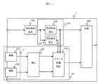
図1は、本発明の撮像装置の一実施例の構成を示す図である。1は本実施例の撮像装置であり、例えば車両の前方に搭載され、信号や標識、障害物などを認識して運転者を支援する安全システムの一部として構成するものである。 FIG. 1 is a diagram showing a configuration of an embodiment of an image pickup apparatus of the present invention.
101、102は撮像部であり、画像センサに光学レンズが装着されている。これらの撮像部は、所定のタイミングで1枚の画像の撮像を繰り返し、撮像した画像を出力する。
撮像部101と撮像部102は、所定の距離で左右に離れて設置され、撮像部101と撮像部102で撮影した画像のずれ、いわゆる視差から、被写体までの距離を算出できる。
The
なお、図1では撮像装置1の構成要素が同一の筐体に収められる例を示したが、例えば撮像部101、102を、他の構成要素とは別の筐体にまとめて収めてもよいし(同図点線枠11)、撮像部101、102をそれぞれ別の筐体に収めて車両に取り付けてもよい。その場合、画像信号は図示しない接続ケーブルで接続すればよい。接続ケーブルを用いて画像を伝送する方法としては、LVDS(Low Voltage Differential Signaling)方式の差動伝送路を用いた伝送方法などがある。 Although FIG. 1 shows an example in which the constituent elements of the
また、撮像部101と撮像部102の画像センサをカラー画像センサとすることで、撮像した画像の色情報を取得することが可能になる。 Further, by using color image sensors for the image sensors of the
103は画像補正部であり、撮像部101、102からの画像を取り込み、それぞれの画像の輝度を合わせるように予め計測されている補正値で補正し、さらにレンズによる画像の歪の補正と、撮像部101、102の画像の水平位置を合わせるようにこれも予め計測されている補正値で補正する。補正値の計測は、撮像装置の製造工程で行われる。補正値適用前の装置毎で、特定の被写体を撮像し、取得した画像の輝度が均一になるような画素毎の輝度補正値、およびレンズ歪を打ち消し、画像が水平になるような画素毎の幾何補正値を求め、それぞれ補正テーブルとして、装置毎に例えば図示しない不揮発性メモリに保存しておく。 An
104は物体情報取得部であり、物体の距離情報を含む物体情報を取得する。本実施形態では、物体情報取得部104は、前記複数の撮像部の少なくとも一つで取得した画像から物体を検出し、前記物体の距離を検出する。即ち、物体情報取得部104は、単眼処理により物体を検出することから、単眼距離検出部と呼ぶことができる。また、物体情報取得部104は、後述するステレオ距離検出部との関係から、第1の距離検出部と特定することもできる。 An object
物体情報取得部104は、撮像部101または撮像部102のどちらの画像を入力して物体の領域と距離を検出する。物体を検出する方法としては、例えば次のような方法がある。物体情報取得部104は、撮像部101または撮像部102のどちらかの画像を取り込み、取り込んだ画像の中で、想定している交通信号や道路標識などを検出する。この検出方法としては、例えば、画像の中で輝度分布やエッジの形状情報と、参照データとして保持しているパタンデータとの類似量から交通信号や道路標識などの物体を検出する方法などがある。これにより、画像中の物体とその画面上の位置が把握できる。さらに、物体情報取得部104は、例えば検出した物体の画面上の高さと大きさにより、その距離を大まかに検出することができる。物体情報取得部104は、この検出結果を後述の処理領域設定部106、および探索範囲設定部107に出力する。 The object
105はもう一つの距離検出部(即ち、第2の距離検出部)としてのステレオ距離検出部であり、画像補正部103からの画像を入力して被写体の距離を検出する。距離を検出する方法として例えば次のような方法がある。ステレオ距離検出部105は、画像補正部103からの画像を取り込み、視差の算出を行う。前述のように、撮像部101と撮像部102は所定の距離で左右に離れて設置されているので、撮像した画像は視差を持つ。この視差を算出するいわゆるステレオ処理を行う。視差の算出手法としては、例えば、ブロックマッチング方式がある。ステレオ距離検出部105は、例えば画像補正選択部103からの画像のうち、後述の処理領域設定部106により指定された画像の領域について距離検知を行う。具体的には、まず、撮像部101の指定された画像領域上から小さく切出した所定のサイズのブロック領域に対応する、撮像部102の画像上の同じ被写体が映っている領域を水平方向に1画素ずつずらしていき探索する。その際、水平方向への探索範囲として、後述の探索範囲設定部107により指定された画素数分の探索範囲について探索を行う。そして撮像部101と撮像部102における一致したブロック領域の位置の差が視差となる。この視差を用いてブロック領域に映っている対象物の実環境での距離を求めることができる。なお、この例は、距離を求める対象となる画像要素として、ブロック領域を採用したものである。一致比較の手法としては、例えば、ブロック領域内の画素の輝度の差分の総和が小さくなった位置を視差とする。なお、検出される距離は、撮像部101、撮像部102のレンズ焦点距離、撮像部101と撮像部102の距離、上記で求めた視差、および撮像センサの画素ピッチから求められることは公知である。ただし、距離の算出方法はこれに限定するものではない。また、距離を求める対象となる画像要素として、上述のブロック領域に限られず、撮像センサを構成する個々の画素を採用してもよい。
110は、探索条件設定部であり、ステレオ距離検出部105により、前記複数の撮像部のうちの一つで撮影された基準画像内の特定の画像要素に対応する画像要素を他の撮像部で撮影される参照画像内で探索する際の条件を設定する。具体的には、探索条件設定部110は、後述する処理領域設定部106と探索範囲設定部107とを備える。
106は、処理領域設定部であり、物体情報取得部104の結果に基づいて、後述のステレオ距離検出部105において距離を検出する画像の領域を指定し、また、後述の認識部108において物体を認識する画像の位置を指定する。 A processing
107は、探索範囲設定部であり、物体情報取得部104の結果に基づいて、ステレオ距離検出部105において距離を検出するための探索範囲を設定する。 A search
ステレオ距離検出部105は、補正部103からの画像の内、指定された領域について、前述の距離検出を行い、その結果を後述の認識部108に出力する。これにより、距離ステレオ距離検出部105による距離検出の領域および探索範囲を限定することが可能となり、処理負荷の増大を回避できる。 The stereo
108は認識部であり、ステレオ距離検出部105からの検出結果と処理領域設定部106からの領域指定を受け取り、画像上物体の認識を行い、認識結果の情報を撮像装置1の外部へ出力する。ステレオ距離検出部105で求めた、処理領域設定部106で指定された領域の距離情報に基づいて物体を認識する。物体を認識する方法は、例えば、ほぼ同一の距離を示す距離情報が近くに存在する場合、それらを一つの集合としてグループ化し、そのグループの大きさが一定以上のときにそのグループを物体とみなす。そして、検出したグループの大きさと形状に基づき、例えば車両や歩行者であることを検出する。物体の大きさや形状は、参照データとしてあらかじめ保持しているパタンデータとの比較から検出する方法がある。この処理方式によれば、自車両から前方の物体たとえば歩行者や車両の距離が精度よく得られるので、自車両の減速や停止などの衝突回避のための情報として用いられる。 A
なお、撮像装置1は、例えば点線枠12内の撮像部101、102、画像補正部103、ステレオ距離検出部105は電子回路で構成され、それ以外の構成要素は図示しないマイコンなどによるソフトウェア処理で実現される。 In the
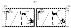
図2は、本発明の撮像装置の一実施例で撮像される撮像画像の一例を示す図である。同図中、1001は撮像部101で撮像され、補正部103で補正された撮像画像を、1002は、撮像部102で撮像され、補正部103で補正された撮像画像を示す。202、203、204は被写体である。 FIG. 2 is a diagram showing an example of a picked-up image picked up by an embodiment of the image pickup apparatus of the present invention. In the figure,
また、201、208は、撮像画像1001および撮像画像1002のうち共通して撮像されている領域である共通撮像領域を示す。前述のように撮像画像1001と撮像画像1002の間には、共通して撮像されている領域のずれがあり、このずれ量すなわち視差により、被写体の距離を算出する。
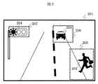
図3は、本発明の撮像装置の一実施例で撮像される撮像画像と領域制御の一例を示す図である。同図中201は、例えば撮像部101で撮像され、補正部103で補正された撮像画像のうち、前述のように撮像部102で撮像された画像と共通して撮像されている領域を示す。 FIG. 3 is a diagram showing an example of a captured image captured by an embodiment of the image capturing apparatus of the present invention and area control. In the figure,
205、206および207は撮像画像201のうち、処理領域設定部106で指定された処理領域であり、処理領域205、206、207は、ステレオ距離検出部105にて距離検出処理が行われる処理領域である。即ち、処理領域205、206、207は、それぞれ物体情報取得部104において歩行者202、対向車203、交通信号204の検出とその粗い距離検出処理が行われた後、その結果から処理領域設定部106によって領域を指定した、共通撮像領域のうちの一部分の領域であり、この領域では、ステレオ距離検出部105において該領域内で該一部領域内の画像要素についての距離が前記複数の撮影画像間の視差に基づいて算出される。 205, 206, and 207 are processing areas designated by the processing
図4は、本発明の撮像装置の一実施例の距離と視差の関係、および探索範囲設定部107による探索範囲の設定方法の一例を示す図である。視差は画素の単位で表され、前述の撮像部101で撮影された画像から撮像部102で撮影された画像のずれ量を示す。例えば前述の歩行者202が、物体情報取得部104において約5mと検出された場合、その際の視差としては、同図から60画素となる。従って、探索範囲設定部107は、歩行者202の距離の探索範囲として、60画素を中心に50画素から70画素の範囲を処理領域205に対して設定する。同様に、交通信号204、対向車203の領域である処理領域207、206に対し、それぞれ約20m、約50mと距離が検出された場合、探索範囲として、25画素から40画素、1画素から10画素をそれぞれ設定する。これにより、各処理領域において、物体情報取得部104で検出した距離を中心に、限られた画素数の範囲の視差を探索すればよく、処理負荷が軽減される。また、設定した探索範囲では、距離が検出できなかった場合は、設定した探索範囲を広げて、広げた範囲の探索処理をすることで処理負荷を最小限に抑えることができる。例えば、沿道の人物ポスターなどを人物として誤って検出し、物体情報取得部104が実際の距離とは異なる距離と検出してしまう場合などが想定される。 FIG. 4 is a diagram showing an example of the relationship between the distance and the parallax and the method of setting the search range by the search
図5は、本発明の撮像装置の一実施例の処理タイミングを示す図である。同図中、(5−1)は物体情報取得部104の処理タイミングを、(5−2)はステレオ距離検出部105の処理タイミングを示す。 FIG. 5 is a diagram showing a processing timing of an embodiment of the image pickup apparatus of the present invention. In the figure, (5-1) shows the processing timing of the object
(5−1)では、撮像画像201について、物体情報取得部104にて物体検出と前述のように物体の粗い距離検出処理が行われる。また、(5−2)では、処理領域設定部106の指定するそれぞれの処理領域205,206,207について、探索範囲設定部107の指定する各処理領域の探索範囲についてステレオ距離検出部105において距離検出が行われる。処理の順番として、自車両から近い物体を含む領域から処理をすることで、後続の認識部108でより早く認識が可能となり、安全性を確保することができる。 In (5-1), the object
このように、ステレオ距離検出部105における距離検出処理は、指定された必要な処理領域についてのみ、それぞれの処理領域において必要最小限の探索範囲で距離検出処理が行われるので、撮像した画像の全領域について全範囲の距離探索をする必要はなく、処理の負荷が低減できる。 As described above, in the distance detection processing in the stereo
図6は、本発明の撮像装置の一実施例の処理フローを示す図である。まず、撮像部101および102により画像を撮影する(S601:Sはステップを表す)。撮影したそれぞれの画像は、画像補正部103により前述した通り輝度補正、レンズ歪補正や水平位置合わせが行われる(S602)。次に、物体情報取得部104により、物体の検出とそのおおよその距離が検出される(S603)。その検出結果のうち、処理領域設定部106において、検出した物体の位置情報から、処理すべき領域情報をステレオ距離検出部105に出力し(S604)、また、探索範囲設定部107において、検出した物体の距離情報から、その物体を含む領域での探索すべき探索範囲を決定しステレオ距離検出部105に出力する(S605)。 FIG. 6 is a diagram showing a processing flow of an embodiment of the image pickup apparatus of the present invention. First, an image is captured by the
次に、得られた検出結果に基づいてステレオ距離検出部105により、指定された各領域において、それぞれの探索範囲で詳細な距離を検出する(S406)。 Next, based on the obtained detection result, the stereo
最後に認識部108により、各処理領域の物体の距離検出結果に基づいて、物体の認識処理を行い、認識結果を出力する(S607)。これらの処理を例えば1フレーム毎に繰り返し行う。 Finally, the
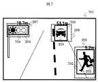
図7は、本発明の撮像装置の一実施例における撮影画像と認識結果の一例を示す図である。701はある時点で撮像部101により撮像された画像であり、撮像部102もほぼ同様の画像を撮影し取得している。また、702、703、704は物体の認識結果であり、画像内の枠と距離表示は撮像した画像にはなく、画像上に重ねて明示的に示したものである。 FIG. 7 is a diagram showing an example of a captured image and a recognition result in the embodiment of the image pickup apparatus of the present invention. An
前述の処理領域205から検出した歩行者202が距離5.2mと、処理領域206から検出した対向車203が距離53.1m、処理領域207の交通信号204が距離19.7mの位置にあることを検出している。このように撮影した画像全体に亘って精度の高い物体の距離検出を実現できる。 The
本実施例によれば、撮影画像から物体とその距離を粗く検出し、その結果に基づいて物体を含む領域に対し、距離の探索範囲を限定して正確な距離検出処理を行うので、撮像画像全体についての物体認識が、処理負荷の増大なく可能になる。 According to the present embodiment, the object and its distance are roughly detected from the photographed image, and based on the result, accurate distance detection processing is performed by limiting the distance search range to the area including the object. Object recognition for the whole is possible without increasing the processing load.
図8は、本発明の撮像装置の別の実施例の構成を示す図である。撮像装置1は、自動車などの車両に搭載されており、同図中801は車両制御部である。認識部108の出力が車両制御部801に入力されている。また、認識部108には、撮影画像中の距離情報から、路面部分を他の物体と分離して路面領域として検出し、その領域を物体情報取得部104に出力する路面検出部1081を備え、さらに認識部108は、図示しないが車両速度や操舵角などの車両情報を入力して、自車両の走行経路を予測し、物体情報取得部104に出力する走行経路予測部1082を備える。 FIG. 8 is a diagram showing the configuration of another embodiment of the image pickup apparatus of the present invention. The
物体情報取得部104は、路面検出部1081により検出された路面情報を入力し、路面上の物体を優先的に処理し、処理領域設定部106、探索範囲設定部107、およびステレオ距離検出部105で正確な距離を検出し認識部108にて認識することで、自車両の障害物をいち早く認識でき、安全な走行を維持できる。また、物体情報取得部104は、走行経路予測部1082から、これから走行していく経路上の物体を優先的に処理し、上記のように自車両の走行経路上の障害物を認識して、安全な走行を実現できる。 The object
また、探索範囲設定部107は自車両の車両速度を入力して、例えば速度が早い場合は探索範囲を広く設定し、遅い場合は狭く設定することで、最小限の処理量で距離検出処理を確実に行うことができる。 In addition, the search
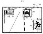
さらに、図9に示すように、例えば処理領域設定部106は画像全体である処理領域901を処理領域とし、その際、探索制御部は、前述のように60画素を中心に50画素から70画素の範囲を探索範囲に設定し、自車両の例えば2mから10mまでといった近傍距離を検出するようにすることで、自車両の近傍については、全画面を距離検出の対象とすることができ、安全性を高めることできる。 Further, as shown in FIG. 9, for example, the processing
また、物体情報取得部104は、近接する複数の物体を例えばまとめて処理し、処理領域設定部106はそれを一つの領域とし、また探索範囲設定部107は物体情報取得部104で検出しまとめた一つの領域内の物体の距離を包括して探索範囲を設定することで、多数の物体が存在する場合にも対応できる。 Further, the object
図8の車両制御部801は、認識部108による認識結果を受け、車両の他の図示しない装置に対し制御を行う。車両の制御としては、歩行者の接近や、赤信号や道路標識を検出したことによる、運転者への警告ランプの点灯、警告音の発生、ブレーキ制動による減速、停止制御、先行車追従時のスロットル、ブレーキ制御、その他の衝突回避や車線維持のための舵角制御などである。これらの車両制御情報は撮像装置1から図示しない他の装置に対して、車内ネットワークを介して出力する。 The
なお、図8では車両制御部801は撮像装置1とは同一筐体に収められる例を示したが、それに限るものではなく、前述のように、撮像部101、102を別筐体としてもよい。 Although FIG. 8 shows an example in which the
図10は、本発明の撮像装置のさらに別の実施例の構成を示す図である。901はネットワーク撮像部、903はLAN(LocalAreaNetwork)であり、904は制御部である。ネットワーク撮像部901は、LAN903を介して制御部904と接続されている。また、902は画像圧縮・インタフェース部、905はネットワークインタフェース部、906は画像伸張部である。 FIG. 10 is a diagram showing the configuration of still another embodiment of the image pickup apparatus of the present invention.
撮像部101、撮像部102で撮影した画像は、画像補正部103において、輝度補正、レンズ歪補正や水平位置合わせが行われる。次に画像圧縮・インタフェース部902は、画像補正部103からの画像を圧縮してLAN903に送信する。画像圧縮の方式としては処理時間を少なくするため、複数の画像の時間的相関関係を使わず、一枚の画像内で圧縮を行う画面内圧縮方式を用いる方式がある。また、映像圧縮符号化方式を選択して切り換えてもよい。 The images corrected by the
画像圧縮・インタフェース部902は、圧縮符号化データを生成し、所定のネットワークプロトコルに従ってデータを送信する。なお、画像補正部103は、画像圧縮・インタフェース部902の前段で処理することにより、レンズ歪などを補正した後に画像圧縮することで、画像圧縮の高効率化と高画質化が見込まれるが、制御部904の画像伸張部906の後段に設けてもよい。 The image compression/
制御部904においては、ネットワークインタフェース部905において、圧縮画像データの受信を、LAN903を介して行う。制御部904のネットワークインタフェース部905で受信した圧縮画像データは、画像伸張部906において元の画像に伸張され、物体情報取得部104により検出された物体について、処理領域設定部106、および探索範囲設定部107が前述の処理を行う。これ以降の処理は前述の通りである。 In the
本実施例によれば、LAN906を介して画像や撮像タイミング情報をやり取りするので、撮像部側の処理量を減らすことができ、撮像部側の軽量化、低消費電力化、筐体が小さくなることによる、車両設置への寸法制限を低減することが可能になる。 According to the present embodiment, since the image and the image pickup timing information are exchanged via the
図11は、本発明の別の実施例の構成を示す図である。この実施例では、物体情報取得部104の入力情報を撮像部101、102以外で構成された、距離情報が得られるセンサから得るものである。例えば入力情報としては、図示しないがレーダや、赤外線センサなどのセンサから得る情報であり、対象範囲の物体の距離を求めることができる。それ以降の動作は前述の通りである。 FIG. 11 is a diagram showing the configuration of another embodiment of the present invention. In this embodiment, the input information of the object
なお、本発明は上記した実施例に限定されるものではなく、様々な変形例が含まれる。例えば、上記した実施例は本発明を分かりやすく説明するために詳細に説明したものであり、必ずしも説明した全ての構成を備えるものに限定されるものではない。また、ある実施例の構成の一部を他の実施例の構成に置き換えることが可能であり、また、ある実施例の構成に他の実施例の構成を加えることも可能である。また、各実施例の構成の一部について、他の構成の追加・削除・置換をすることが可能である。 It should be noted that the present invention is not limited to the above-described embodiments, but includes various modifications. For example, the above-described embodiments have been described in detail in order to explain the present invention in an easy-to-understand manner, and are not necessarily limited to those having all the configurations described. Further, it is possible to replace a part of the configuration of one embodiment with the configuration of another embodiment, and to add the configuration of another embodiment to the configuration of one embodiment. Further, with respect to a part of the configuration of each embodiment, other configurations can be added/deleted/replaced.
また、上記の各構成は、それらの一部又は全部が、ハードウェアで構成されても、プロセッサでプログラムが実行されることにより実現されるように構成されてもよい。また、制御線や情報線は説明上必要と考えられるものを示しており、製品上必ずしも全ての制御線や情報線を示しているとは限らない。実際には殆ど全ての構成が相互に接続されていると考えてもよい。 Further, each of the above-described configurations may be partially or entirely configured by hardware, or may be configured to be realized by executing a program by a processor. Further, the control lines and information lines shown are those that are considered necessary for explanation, and not all the control lines and information lines on the product are necessarily shown. In practice, it may be considered that almost all configurations are connected to each other.
1…撮像装置、101〜102…撮像部、103…画像補正部、104…物体情報取得部、105…ステレオ距離検出部、106…処理領域設定部、107…探索範囲設定部、108…認識部、201…共通撮像領域、202〜204…被写体、205〜207…処理領域、702〜704…認識結果、801…車両制御部、901…ネットワーク撮像部、902…画像圧縮・インタフェース部、903…LAN、904…制御部、905…ネットワークインタフェース部、906…画像伸張部。DESCRIPTION OF
Claims (4)
Translated fromJapanese物体の距離情報を含む物体情報を取得する物体情報取得部と、
前記複数の撮像部のうちの一つで撮影された基準画像内の特定の画像要素に対応する画像要素を他の撮像部で撮影される参照画像内で探索する際の条件を設定する探索条件設定部と、
前記探索条件設定部で設定された条件に基づいて前記探索を行い、前記探索によって得られる視差に基づいて前記物体の距離を検出するステレオ距離検出部と、を備え、
前記物体情報取得部は、前記撮像部で取得した画像から単眼処理により物体を検出し、
前記探索条件設定部は、前記物体の検出情報に基づいて、前記探索を行う際の探索範囲を設定する、物体距離検出装置。A plurality of imaging units,
An object information acquisition unit that acquires object information including distance information of the object,
A search condition that sets a condition for searching an image element corresponding to a specific image element in a standard image captured by one of the plurality of image capturing units in a reference image captured by another image capturing unit. Setting section,
A stereo distance detection unit that performs the search based on the condition set by the search condition setting unit, and detects the distance of the object based on the parallax obtained by the search,
The object information acquisition unit detects an object by monocular processing from the image acquired by the imaging unit,
The object distance detection device, wherein the search condition setting unit sets a search range when performing the search based on the detection information of the object.
物体の距離情報を含む物体情報を取得する物体情報取得部と、
前記複数の撮像部のうちの一つで撮影された基準画像内の特定の画像要素に対応する画像要素を他の撮像部で撮影される参照画像内で探索する際の条件を設定する探索条件設定部と、
前記探索条件設定部で設定された条件に基づいて前記探索を行い、前記探索によって得られる視差に基づいて前記物体の距離を検出するステレオ距離検出部と、
走行経路を予測する走行経路予測手段と、を備え、
前記物体情報取得部は、前記走行経路予測手段で予測した経路上の物体の距離を取得し、
前記探索条件設定部は、前記物体の検出情報に基づいて、前記探索を行う際の探索範囲を設定する、物体距離検出装置。A plurality of imaging units,
An object information acquisition unit that acquires object information including distance information of the object,
A search condition that sets a condition for searching an image element corresponding to a specific image element in a standard image captured by one of the plurality of image capturing units in a reference image captured by another image capturing unit. Setting section,
Performing the search based on the conditions set in the search condition setting unit, a stereo distance detecting unit that detects the distance of the object based on the parallax obtained by the search,
Anda travel route prediction means for predicting a travel route,
The object information acquisition unit acquires the distance of the object on the route predicted by the travel route prediction unit,
The object distance detection device, wherein the search condition setting unit sets a search range when performing the search based on the detection information of the object.
物体の距離情報を含む物体情報を取得する物体情報取得部と、
前記複数の撮像部のうちの一つで撮影された基準画像内の特定の画像要素に対応する画像要素を他の撮像部で撮影される参照画像内で探索する際の条件を設定する探索条件設定部と、
前記探索条件設定部で設定された条件に基づいて前記探索を行い、前記探索によって得られる視差に基づいて前記物体の距離を検出するステレオ距離検出部と、を備え、
前記探索条件設定部は、前記物体の検出情報に基づいて、前記探索を行う際の探索範囲を設定し、
前記探索条件設定部は、
前記物体情報取得部で得られた物体を含む処理領域を前記参照画像内で設定する処理領域設定部と、
前記探索を行う探索範囲を前記物体情報取得部で検出された物体の距離情報に基づいて設定する探索範囲設定部と、を備え、
前記探索範囲設定部は、車速に応じて探索範囲を変化させ設定する、物体距離検出装置。A plurality of imaging units,
An object information acquisition unit that acquires object information including distance information of the object,
A search condition that sets a condition for searching an image element corresponding to a specific image element in a standard image captured by one of the plurality of image capturing units in a reference image captured by another image capturing unit. Setting section,
A stereo distance detection unit that performs the search based on the condition set by the search condition setting unit, and detects the distance of the object based on the parallax obtained by the search,
The search condition setting unit, based on the detection information of the object, sets a search range when performing the search,
The search condition setting unit,
A processing region setting unit that sets a processing region including the object obtained by the object information acquisition unit in the reference image,
A search range setting unit that sets a search range for performing the search based on distance information of the object detected by the object information acquisition unit;
The object range detection device, wherein the search range setting unit changes and sets the search range according to a vehicle speed.
物体の距離情報を含む物体情報を取得する物体情報取得部と、
前記複数の撮像部のうちの一つで撮影された基準画像内の特定の画像要素に対応する画像要素を他の撮像部で撮影される参照画像内で探索する際の条件を設定する探索条件設定部と、
前記探索条件設定部で設定された条件に基づいて前記探索を行い、前記探索によって得られる視差に基づいて前記物体の距離を検出するステレオ距離検出部と、を備え、
前記探索条件設定部は、前記物体の検出情報に基づいて、前記探索を行う際の探索範囲を設定し、
前記探索条件設定部は、
前記物体情報取得部で得られた物体を含む処理領域を前記参照画像内で設定する処理領域設定部と、
前記探索を行う探索範囲を前記物体情報取得部で検出された物体の距離情報に基づいて設定する探索範囲設定部と、を備え、
前記探索範囲設定部は、前記ステレオ距離検出部で前記物体の距離が検出できなかった場合、前記探索範囲を拡大し、
前記ステレオ距離検出部において、前記拡大した探索範囲について距離を検出する、物体距離検出装置。A plurality of imaging units,
An object information acquisition unit that acquires object information including distance information of the object,
A search condition that sets a condition for searching an image element corresponding to a specific image element in a standard image captured by one of the plurality of image capturing units in a reference image captured by another image capturing unit. Setting section,
A stereo distance detection unit that performs the search based on the condition set by the search condition setting unit, and detects the distance of the object based on the parallax obtained by the search,
The search condition setting unit, based on the detection information of the object, sets a search range when performing the search,
The search condition setting unit,
A processing region setting unit that sets a processing region including the object obtained by the object information acquisition unit in the reference image,
A search range setting unit that sets a search range for performing the search based on distance information of the object detected by the object information acquisition unit ;
The search range setting unit, if the distance of the object cannot be detected by the stereo distance detection unit, expands the search range,
An object distance detecting device for detecting a distance in the expanded search range in the stereo distance detecting unit.
Priority Applications (5)
| Application Number | Priority Date | Filing Date | Title |
|---|---|---|---|
| JP2016113995AJP6723079B2 (en) | 2016-06-08 | 2016-06-08 | Object distance detection device |
| EP17810171.3AEP3470780B1 (en) | 2016-06-08 | 2017-05-31 | Object distance detection device |
| CN201780017942.2ACN109196304B (en) | 2016-06-08 | 2017-05-31 | Object distance detection device |
| US16/097,366US11029150B2 (en) | 2016-06-08 | 2017-05-31 | Object distance detection device |
| PCT/JP2017/020197WO2017212992A1 (en) | 2016-06-08 | 2017-05-31 | Object distance detection device |
Applications Claiming Priority (1)
| Application Number | Priority Date | Filing Date | Title |
|---|---|---|---|
| JP2016113995AJP6723079B2 (en) | 2016-06-08 | 2016-06-08 | Object distance detection device |
Publications (2)
| Publication Number | Publication Date |
|---|---|
| JP2017219427A JP2017219427A (en) | 2017-12-14 |
| JP6723079B2true JP6723079B2 (en) | 2020-07-15 |
Family
ID=60578699
Family Applications (1)
| Application Number | Title | Priority Date | Filing Date |
|---|---|---|---|
| JP2016113995AActiveJP6723079B2 (en) | 2016-06-08 | 2016-06-08 | Object distance detection device |
Country Status (5)
| Country | Link |
|---|---|
| US (1) | US11029150B2 (en) |
| EP (1) | EP3470780B1 (en) |
| JP (1) | JP6723079B2 (en) |
| CN (1) | CN109196304B (en) |
| WO (1) | WO2017212992A1 (en) |
Families Citing this family (9)
| Publication number | Priority date | Publication date | Assignee | Title |
|---|---|---|---|---|
| EP3584120B1 (en)* | 2017-02-17 | 2021-04-14 | Sumitomo Heavy Industries, Ltd. | Work machine surroundings monitoring system |
| EP3492338B1 (en)* | 2017-11-30 | 2024-11-06 | Mitsubishi Electric R & D Centre Europe B.V. | Automatic remote control of a moving conveyance |
| TWI647427B (en)* | 2018-01-10 | 2019-01-11 | 緯創資通股份有限公司 | Object distance estimation method and electronic device |
| US20210248756A1 (en)* | 2018-05-10 | 2021-08-12 | Sony Corporation | Image processing apparatus, vehicle-mounted apparatus, image processing method, and program |
| TW202102392A (en)* | 2019-07-02 | 2021-01-16 | 帷享科技股份有限公司 | Driving safety enhancing system and method for making or enabling highly accurate judgment and providing advance early warning |
| JP7510801B2 (en) | 2020-07-01 | 2024-07-04 | 日産自動車株式会社 | Driving support method and driving support device |
| CN111914817B (en)* | 2020-09-21 | 2024-04-02 | 南京航空航天大学 | A road recognition method and system based on seed points |
| DE102021206879A1 (en)* | 2021-06-30 | 2023-01-05 | Fraunhofer-Gesellschaft zur Förderung der angewandten Forschung eingetragener Verein | Process for the optical monitoring and/or determination of properties on samples |
| US20240262386A1 (en)* | 2023-02-02 | 2024-08-08 | Motional Ad Llc | Iterative depth estimation |
Family Cites Families (26)
| Publication number | Priority date | Publication date | Assignee | Title |
|---|---|---|---|---|
| JP3263931B2 (en) | 1999-09-22 | 2002-03-11 | 富士重工業株式会社 | Stereo matching device |
| US7221777B2 (en) | 2002-07-02 | 2007-05-22 | Honda Giken Kogyo Kabushiki Kaisha | Image analysis device |
| JP3936313B2 (en)* | 2002-07-02 | 2007-06-27 | 本田技研工業株式会社 | Image recognition device |
| JP2005331389A (en)* | 2004-05-20 | 2005-12-02 | Toyota Motor Corp | Inter-vehicle distance control device |
| DE102004061998A1 (en)* | 2004-12-23 | 2006-07-06 | Robert Bosch Gmbh | Stereo camera for a motor vehicle |
| KR100813100B1 (en)* | 2006-06-29 | 2008-03-17 | 성균관대학교산학협력단 | Real-time scalable stereo matching system and method |
| JP2008304202A (en)* | 2007-06-05 | 2008-12-18 | Konica Minolta Holdings Inc | Method and apparatus for distance image generation and program |
| JP2008309637A (en)* | 2007-06-14 | 2008-12-25 | Konica Minolta Holdings Inc | Obstruction measuring method, obstruction measuring apparatus, and obstruction measuring system |
| JP2009092551A (en)* | 2007-10-10 | 2009-04-30 | Konica Minolta Holdings Inc | Method, apparatus and system for measuring obstacle |
| JP2012002683A (en) | 2010-06-17 | 2012-01-05 | Fuji Electric Co Ltd | Stereo image processing method and stereo image processing device |
| CN101999972B (en)* | 2010-11-24 | 2013-07-03 | 上海理工大学 | Stereoscopic vision based auxiliary walking device for blindmen and auxiliary method thereof |
| CN102069770A (en)* | 2010-12-16 | 2011-05-25 | 福州名品电子科技有限公司 | Automobile active safety control system based on binocular stereo vision and control method thereof |
| JP5591730B2 (en) | 2011-02-10 | 2014-09-17 | 富士重工業株式会社 | Environment recognition device |
| WO2013069130A1 (en)* | 2011-11-10 | 2013-05-16 | 三菱電機株式会社 | Vehicle system |
| JP6035774B2 (en) | 2012-02-24 | 2016-11-30 | 株式会社リコー | Image processing apparatus, image processing method, and vehicle |
| JP5977047B2 (en)* | 2012-02-29 | 2016-08-24 | 株式会社日本自動車部品総合研究所 | Vehicle travel control device |
| JP6071257B2 (en)* | 2012-06-07 | 2017-02-01 | キヤノン株式会社 | Image processing apparatus, control method therefor, and program |
| JP5829980B2 (en) | 2012-06-19 | 2015-12-09 | トヨタ自動車株式会社 | Roadside detection device |
| JP5982298B2 (en)* | 2013-02-21 | 2016-08-31 | シャープ株式会社 | Obstacle detection device and obstacle detection method |
| JP2015230703A (en)* | 2014-06-06 | 2015-12-21 | 日本電産エレシス株式会社 | Object detection device and object detection method |
| KR101882931B1 (en)* | 2014-07-10 | 2018-07-30 | 삼성전자주식회사 | Multi view image display apparatus and disparity estimation method of thereof |
| JP6548893B2 (en)* | 2014-11-18 | 2019-07-24 | 日立オートモティブシステムズ株式会社 | Roadway recognition device and travel support system using the same |
| JP6356586B2 (en)* | 2014-11-28 | 2018-07-11 | 株式会社デンソー | Vehicle travel control device |
| CN112902975B (en)* | 2015-02-10 | 2024-04-30 | 御眼视觉技术有限公司 | Autonomous vehicle navigation method, readable device, server, vehicle and system |
| JP6623044B2 (en)* | 2015-11-25 | 2019-12-18 | 日立オートモティブシステムズ株式会社 | Stereo camera device |
| JP6838340B2 (en)* | 2016-09-30 | 2021-03-03 | アイシン精機株式会社 | Peripheral monitoring device |
- 2016
- 2016-06-08JPJP2016113995Apatent/JP6723079B2/enactiveActive
- 2017
- 2017-05-31CNCN201780017942.2Apatent/CN109196304B/enactiveActive
- 2017-05-31USUS16/097,366patent/US11029150B2/enactiveActive
- 2017-05-31WOPCT/JP2017/020197patent/WO2017212992A1/ennot_activeCeased
- 2017-05-31EPEP17810171.3Apatent/EP3470780B1/enactiveActive
Also Published As
| Publication number | Publication date |
|---|---|
| CN109196304B (en) | 2021-07-30 |
| US20190145768A1 (en) | 2019-05-16 |
| EP3470780B1 (en) | 2025-07-16 |
| JP2017219427A (en) | 2017-12-14 |
| EP3470780A1 (en) | 2019-04-17 |
| US11029150B2 (en) | 2021-06-08 |
| EP3470780A4 (en) | 2020-02-26 |
| CN109196304A (en) | 2019-01-11 |
| WO2017212992A1 (en) | 2017-12-14 |
Similar Documents
| Publication | Publication Date | Title |
|---|---|---|
| JP6723079B2 (en) | Object distance detection device | |
| JP6660751B2 (en) | Imaging device | |
| JP5663352B2 (en) | Image processing apparatus, image processing method, and image processing program | |
| JP7278846B2 (en) | OBJECT POSITION DETECTION DEVICE, TRIP CONTROL SYSTEM, AND TRIP CONTROL METHOD | |
| JP2007172035A (en) | Onboard image recognition device, onboard imaging device, onboard imaging controller, warning processor, image recognition method, imaging method and imaging control method | |
| JP6601506B2 (en) | Image processing apparatus, object recognition apparatus, device control system, image processing method, image processing program, and vehicle | |
| US10595003B2 (en) | Stereo camera apparatus and vehicle comprising the same | |
| US8160300B2 (en) | Pedestrian detecting apparatus | |
| CN114521180A (en) | Object detection device, travel control system, and travel control method | |
| JP6899673B2 (en) | Object distance detector | |
| JP2008165595A (en) | Obstacle detection method, obstacle detection device, obstacle detection system | |
| JP2015230703A (en) | Object detection device and object detection method | |
| JP6891082B2 (en) | Object distance detector | |
| US11157755B2 (en) | Image processing apparatus | |
| CN112544066A (en) | Image processing apparatus | |
| KR101982091B1 (en) | Surround view monitoring system | |
| US20200111227A1 (en) | Orientation detection apparatus for vehicle, image processing system, vehicle, and orientation detection method for vehicle | |
| JP4797441B2 (en) | Image processing apparatus for vehicle | |
| JP2013161187A (en) | Object recognition device | |
| JP2013161188A (en) | Object recognition device | |
| CN119445497A (en) | Information processing device |
Legal Events
| Date | Code | Title | Description |
|---|---|---|---|
| A521 | Request for written amendment filed | Free format text:JAPANESE INTERMEDIATE CODE: A523 Effective date:20160610 | |
| RD04 | Notification of resignation of power of attorney | Free format text:JAPANESE INTERMEDIATE CODE: A7424 Effective date:20170120 | |
| RD04 | Notification of resignation of power of attorney | Free format text:JAPANESE INTERMEDIATE CODE: A7424 Effective date:20170126 | |
| A621 | Written request for application examination | Free format text:JAPANESE INTERMEDIATE CODE: A621 Effective date:20190207 | |
| A521 | Request for written amendment filed | Free format text:JAPANESE INTERMEDIATE CODE: A523 Effective date:20190208 | |
| A131 | Notification of reasons for refusal | Free format text:JAPANESE INTERMEDIATE CODE: A131 Effective date:20200218 | |
| RD02 | Notification of acceptance of power of attorney | Free format text:JAPANESE INTERMEDIATE CODE: A7422 Effective date:20200227 | |
| RD04 | Notification of resignation of power of attorney | Free format text:JAPANESE INTERMEDIATE CODE: A7424 Effective date:20200309 | |
| A521 | Request for written amendment filed | Free format text:JAPANESE INTERMEDIATE CODE: A523 Effective date:20200416 | |
| TRDD | Decision of grant or rejection written | ||
| A01 | Written decision to grant a patent or to grant a registration (utility model) | Free format text:JAPANESE INTERMEDIATE CODE: A01 Effective date:20200609 | |
| A61 | First payment of annual fees (during grant procedure) | Free format text:JAPANESE INTERMEDIATE CODE: A61 Effective date:20200623 | |
| R150 | Certificate of patent or registration of utility model | Ref document number:6723079 Country of ref document:JP Free format text:JAPANESE INTERMEDIATE CODE: R150 | |
| S533 | Written request for registration of change of name | Free format text:JAPANESE INTERMEDIATE CODE: R313533 | |
| R350 | Written notification of registration of transfer | Free format text:JAPANESE INTERMEDIATE CODE: R350 | |
| R250 | Receipt of annual fees | Free format text:JAPANESE INTERMEDIATE CODE: R250 | |
| R250 | Receipt of annual fees | Free format text:JAPANESE INTERMEDIATE CODE: R250 |