JP6721574B2 - Blade set, hair cutting device and related manufacturing method - Google Patents
Blade set, hair cutting device and related manufacturing methodDownload PDFInfo
- Publication number
- JP6721574B2 JP6721574B2JP2017514642AJP2017514642AJP6721574B2JP 6721574 B2JP6721574 B2JP 6721574B2JP 2017514642 AJP2017514642 AJP 2017514642AJP 2017514642 AJP2017514642 AJP 2017514642AJP 6721574 B2JP6721574 B2JP 6721574B2
- Authority
- JP
- Japan
- Prior art keywords
- wall portion
- blade
- stationary blade
- movable cutter
- cutter blade
- Prior art date
- Legal status (The legal status is an assumption and is not a legal conclusion. Google has not performed a legal analysis and makes no representation as to the accuracy of the status listed.)
- Active
Links
Images


Classifications
- B—PERFORMING OPERATIONS; TRANSPORTING
- B26—HAND CUTTING TOOLS; CUTTING; SEVERING
- B26B—HAND-HELD CUTTING TOOLS NOT OTHERWISE PROVIDED FOR
- B26B19/00—Clippers or shavers operating with a plurality of cutting edges, e.g. hair clippers, dry shavers
- B26B19/38—Details of, or accessories for, hair clippers, or dry shavers, e.g. housings, casings, grips, guards
- B26B19/3846—Blades; Cutters
- B—PERFORMING OPERATIONS; TRANSPORTING
- B26—HAND CUTTING TOOLS; CUTTING; SEVERING
- B26B—HAND-HELD CUTTING TOOLS NOT OTHERWISE PROVIDED FOR
- B26B19/00—Clippers or shavers operating with a plurality of cutting edges, e.g. hair clippers, dry shavers
- B26B19/02—Clippers or shavers operating with a plurality of cutting edges, e.g. hair clippers, dry shavers of the reciprocating-cutter type
- B26B19/04—Cutting heads therefor; Cutters therefor; Securing equipment thereof
- B26B19/06—Cutting heads therefor; Cutters therefor; Securing equipment thereof involving co-operating cutting elements both of which have shearing teeth
- B—PERFORMING OPERATIONS; TRANSPORTING
- B26—HAND CUTTING TOOLS; CUTTING; SEVERING
- B26B—HAND-HELD CUTTING TOOLS NOT OTHERWISE PROVIDED FOR
- B26B19/00—Clippers or shavers operating with a plurality of cutting edges, e.g. hair clippers, dry shavers
- B26B19/38—Details of, or accessories for, hair clippers, or dry shavers, e.g. housings, casings, grips, guards
- B26B19/3893—Manufacturing of shavers or clippers or components thereof
Landscapes
- Engineering & Computer Science (AREA)
- Life Sciences & Earth Sciences (AREA)
- Forests & Forestry (AREA)
- Mechanical Engineering (AREA)
- Manufacturing & Machinery (AREA)
- Dry Shavers And Clippers (AREA)
Description
Translated fromJapanese本開示は、毛切断器具に関し、具体的には、電気的に作動させられる毛切断器具に関し、より具体的には、そのような器具のためのブレードセットの静止ブレードに関する。ブレードセットは、毛を切断する移動方向において毛を通じて移動させられるように配置されてよい。静止ブレードは、第1の壁部分と、第2の壁部分とで構成されてよく、第1の壁部分及び第2の壁部分は、それらの間に、可動切断ブレードを少なくとも部分的に取り囲み且つ案内するガイドスロットを定める。本開示は、更に、毛切断器具のためのブレードセット及び静止ブレードを製造する方法に関する。 The present disclosure relates to hair-cutting instruments, and in particular to electrically actuated hair-cutting instruments, and more particularly to stationary blades of blade sets for such instruments. The blade set may be arranged to be moved through the bristles in a movement direction for cutting the bristles. The stationary blade may be composed of a first wall portion and a second wall portion, the first wall portion and the second wall portion at least partially surrounding the movable cutting blade therebetween. And the guide slot to guide is defined. The present disclosure further relates to methods of manufacturing blade sets and stationary blades for hair cutting instruments.
国際公開第WO2013/150412A1号は、毛切断器具と、毛切断器具の対応するブレードセットとを開示している。ブレードセットは、静止ブレードと、可動ブレードとを含み、可動ブレードは、毛を切断するために静止ブレードに対して往復式に駆動させられ得る。ブレードセットは、トリミング及びシェービングの両方の作業を可能にするのに特に適する。 WO 2013/150412 A1 discloses a hair-cutting device and a corresponding blade set of the hair-cutting device. The blade set includes a stationary blade and a movable blade, which can be reciprocally driven relative to the stationary blade to cut hair. The blade set is particularly suitable for enabling both trimming and shaving operations.
体毛を切断する目的のために、2つの習慣的に区別される種類の電動器具、即ち、かみそり(レザー)及びヘアトリマ又はクリッパが存在する。一般的に、かみそりは、シェービングのために、即ち、無精ひげのない滑らかな皮膚を得るよう皮膚の高さ(level)で体毛を切るために用いられる。ヘアトリマは、典型的には、毛を皮膚からの選択的な距離で切断するために、即ち、毛を所望の長さに切断するために用いられる。用途の違いは、両方の器具で実施される切断ブレード構成の異なる構造及びアーキテクチャにおいて反映される。 For the purpose of cutting hair, there are two customarily distinguished types of electric appliances: razors (leathers) and hair trimmers or clippers. Generally, razors are used for shaving, that is, for cutting hair at the level of the skin to obtain smooth skin without stubble. Hair trimmers are typically used to cut hair at selective distances from the skin, ie, cut hair to a desired length. The different applications are reflected in the different constructions and architectures of the cutting blade configurations implemented on both instruments.
電気かみそりは、典型的には、フォイル、即ち、極薄の穿孔スクリーンと、フォイルの内側でフォイルに対して移動可能な切断ブレードとを含む。使用中、フォイルを貫通するあらゆる毛が、フォイルの内側に対して動く切断ブレードによって切り落とされて、ひげそりの内側の中空の毛収集部分内に落ちるよう、フォイルの外側は、皮膚に押し付けられて配置される。 Electric razors typically include a foil, i.e., an ultra-thin perforated screen, and a cutting blade that is movable relative to the foil inside the foil. During use, the outside of the foil is pressed against the skin so that any hair that penetrates the foil is cut off by a cutting blade that moves against the inside of the foil and falls into the hollow bristles inside the shave. To be done.
他方、電気ヘアトリマは、典型的には、歯付きエッジを有する概ね2つのカッタブレードを含み、それぞれの歯付きエッジが重なり合うよう、一方が他方の上に配置される。動作中、カッタブレードは、互いに対して往復動し、それらの波の間に捕捉される毛を鋏作用において切り落とす。毛が切り落とされる皮膚より上の精密な高さ(level)は、通常、(スペーサ)ガード又はコームと呼ばれる、追加的な取り付け可能な部品を用いて決定される。 Electric hair trimmers, on the other hand, typically include approximately two cutter blades with toothed edges, one placed over the other such that each toothed edge overlaps. During operation, the cutter blades reciprocate with respect to each other, scissoring the hairs trapped between their waves. The precise level above the skin from which hair is cut off is usually determined using an additional attachable part called a (spacer) guard or comb.
更に、シェービング及びトリミングの両方の目的に基本的に適合させられる組み合わせデバイスが知られている。しかしながら、これらのデバイスは、2つの別個の異なる切断区画、即ち、上で提示したような電動ひげそりの着想に匹敵する構成を含むシェービング区画と、他方ではヘアトリミングの着想に匹敵する構成を含むトリミング区画とを含むに過ぎない。 Furthermore, combination devices are known which are basically adapted for both shaving and trimming purposes. However, these devices include two separate and distinct cutting compartments, a shaving compartment containing a configuration comparable to the idea of electric shaving as presented above, and a trimming comprising a composition comparable to the idea of hair trimming on the other hand. It only contains compartments.
一般的な電気ひげそりは、毛を皮膚より上の所望の異なる長さに切断すること、即ち、精密なトリミング作業に特に適さない。これは、少なくとも部分的に、それらがフォイルを皮膚から、結果的には、カッタブレードを皮膚から離間させる機構を含まないという事実によって説明され得る。しかしながら、たとえそうであるとしても、例えば、間隔コームのような、アタッチメントスペーサ部品を追加することによって、典型的に多数の小さな穿孔を含むフォイルの構成は、毛のうちの最も短く最も堅いものを除く全ての効率的な捕捉を減少させる。 Common electric shave is not particularly suitable for cutting hair to different desired lengths above the skin, ie for precision trimming operations. This may be explained, at least in part, by the fact that they do not include a mechanism that separates the foil from the skin and, consequently, the cutter blade. However, even so, the construction of the foil, which typically contains a large number of small perforations, by adding attachment spacer components, such as spacing combs, will produce the shortest and stiffest of the bristles. Reduces all efficient capture except.
同様に、一般的なヘアトリマは、主として、別個のカッタブレードが、変形しないで鋏作用を行うのに特定の剛性(rigidity)、従って、厚みを必要とするという理由で、シェービングに特に適さない。毛が皮膚の近くで切り落とされるのを妨げるのは、皮膚に面するブレードの最小の所要のブレード厚さである。結果的に、彼/彼女の体毛を剃ること及び刈り込むことの両方を望む使用者は、2つの別個の器具を購入して適用しなければならないことがある。 Similarly, conventional hair trimmers are particularly unsuitable for shaving, primarily because the separate cutter blades require a certain rigidity, and thus thickness, to perform the scissor action without deformation. It is the minimum required blade thickness of the blade facing the skin that prevents hair from being cut off near the skin. As a result, a user who wants to both shave and trim his/her hair may have to purchase and apply two separate appliances.
更に、組み合わせシェービング及びトリミングデバイスは、幾つかの欠点を示す。何故ならば、それらは、基本的に、2つの切断ブレードセット及びそれぞれの駆動機構を必要とするからである。結果的に、これらのデバイスは、標準的な種類の単一目的毛切断器具よりも重く且つ摩耗の影響を受け易く、高価な製造及び組立てプロセスも必要とする。同様に、これらの組み合わせデバイスを操作することは、しばしば、むしろ不快であり且つ複雑であると感じられる。2つの別個の切断区画を含む従来的な組み合わせシェービング及びトリミングデバイスが利用される場合においてさえも、デバイスを取り扱うこと及び異なる動作モードの間で切り換えるは、時間がかかり余り使用者に優しくないと考えられることがある。切断区画は、典型的には、デバイスの異なる場所で設けられるため、誘導精度が、(従って、切断精度も)、減少させられることがある。何故ならば、使用者は、操作中の2つの異なる支配的な保持位置に慣れる必要があるからである。 In addition, the combined shaving and trimming device presents some drawbacks. This is because they basically require two cutting blade sets and their respective drive mechanisms. As a result, these devices are heavier and more susceptible to wear than standard types of single-purpose hair-cutting instruments and also require expensive manufacturing and assembly processes. Similarly, manipulating these combined devices is often felt rather uncomfortable and complicated. Even when a conventional combined shaving and trimming device including two separate cutting compartments is utilized, handling the device and switching between different operating modes is considered time consuming and less user friendly. May be Since the cutting compartments are typically provided at different locations on the device, guidance accuracy (and thus cutting accuracy) may be reduced. This is because the user has to get used to two different dominant holding positions during operation.
上記国際公開第WO2013/150412A1号は、シェービングのために用いられるときに、静止ブレードの第1の部分が皮膚に面する可動ブレードの側に配置され、使用中に、静止ブレードの第2の部分が皮膚から見て外方に面する可動ブレードの側に配置されるよう、可動ブレードを収容する、静止ブレードを含む、ブレードセットを提供することによって、これらの問題の一部に取り組んでいる。更に、歯付き切断エッジで、静止ブレードの第1の部分及び第2の部分は接続され、それにより、可動ブレードのそれぞれの歯を覆う複数の静止歯を形成する。結果的に、可動ブレードは、静止ブレードによって保護される。 The above-mentioned WO 2013/150412 A1 discloses that when used for shaving, the first part of the stationary blade is arranged on the side of the movable blade facing the skin, and in use, the second part of the stationary blade. We address some of these problems by providing a set of blades, including stationary blades, that house the moving blades such that are positioned on the side of the moving blades that faces outwardly from the skin. Further, at the toothed cutting edge, the first portion and the second portion of the stationary blade are connected, thereby forming a plurality of stationary teeth that cover each tooth of the movable blade. As a result, the movable blade is protected by the stationary blade.
この構成は、静止ブレードが増大した強度及び剛性(stiffness)を備えるブレードセットをもたらすことがある限り、有利である。何故ならば、静止ブレードは、皮膚から見て外方を向く可動ブレードの側にも存在するからである。これは、一般的に、可動ブレードの皮膚に面する側で静止ブレードの第1の部分の厚さの減少を可能にすることがある。結果的に、このようにして、可動ブレードは、動作中に皮膚により近づくようになることがあるので、上記ブレードセットは、ヘアシェービング作業に適する。それとは別に、ブレードセットは、ヘアトリミング作業にも特に適する。何故ならば、スロットと交互に生じるそれぞれの歯を含む切断エッジの構成は、より長い毛もスロットに入るのも可能にし、結果的に、可動ブレードと静止ブレードとの間の相対的な切断運動によって切断されるのを可能にするからである。 This configuration is advantageous as long as the stationary blades can result in a blade set with increased strength and stiffness. This is because the stationary blade also exists on the side of the movable blade that faces away from the skin. This may allow a reduction in the thickness of the first portion of the stationary blade, generally on the skin-facing side of the movable blade. As a result, in this way, the movable blade may come closer to the skin during operation, making the blade set suitable for hair shaving operations. Apart from that, the blade set is also particularly suitable for hair trimming operations. Because, the configuration of the cutting edge including the teeth alternating with the slot also allows longer bristles to enter the slot, resulting in relative cutting motion between the movable and stationary blades. Because it allows it to be disconnected.
しかしながら、毛切断デバイス及びそれぞれのブレードセットにおける改良の必要が依然としてある。これは、具体的には、使用者の快適性に関連する特徴、性能(パフォーマンス)に関連する特徴、及び製造に関連する特徴を含む。製造に関連する特徴は、連続生産又は大量生産に適していることを含んでよい。 However, there remains a need for improvements in hair cutting devices and respective blade sets. This specifically includes user comfort related features, performance related features, and manufacturing related features. Manufacturing related features may include suitability for serial or mass production.
代替的な静止カッタブレード並びにシェービング及びトリミングの両方を可能にする対応するブレードセットを提供することが本開示の目的である。具体的には、シェービング作業及びトリミング作業の両方において心地良い使用者経験に寄与する静止ブレード及びブレードセットが提供されてよい。より好ましくは、本開示は、例えば、上で議論したような既知の従来技術の毛切断ブレードにおいて固有の少なくとも幾つかの欠点に取り組んでよい。好ましくは切断作業に必要とされる時間を減少させながら動作性能の改良を示すことがあるブレードセットを提供することが更に有利である。そのような静止ブレードを製造するための対応する方法を提供することが更に好ましい。ブレードセットの製造、特に静止ブレードの製造を費用効率的な方法において並びに適切な工程能力(プロセスケイパビリティ)で許容することがある製造方法を提示することが特に望ましい。 It is an object of the present disclosure to provide alternative stationary cutter blades and corresponding blade sets that allow both shaving and trimming. Specifically, stationary blades and blade sets may be provided that contribute to a pleasing user experience in both shaving and trimming operations. More preferably, the present disclosure may address at least some deficiencies inherent in known prior art hair-cutting blades, such as those discussed above. It would be further advantageous to provide a blade set that may exhibit improved operational performance while preferably reducing the time required for the cutting operation. It is further preferred to provide a corresponding method for manufacturing such a stationary blade. It is particularly desirable to present a manufacturing method which may allow the manufacture of blade sets, especially stationary blades, in a cost-effective manner as well as with suitable process capabilities.
本開示の第1の特徴によれば、毛切断器具のブレードセットのための静止ブレードが提示され、ブレードセットは、毛を切断する移動方向において毛を通じて移動させられるように構成され、静止ブレードは、
− 動作時に皮膚に面する壁として働くように構成される第1の壁部分と、
− 第1の壁部分及び第2の壁部分が、それらの間に、可動カッタブレードを受け入れるように構成されるガイドスロットを定めるよう、第1の壁部分から少なくとも部分的にオフセットさせられる第2の壁部分と、
− 第1の壁部分と第2の壁部分との間で前記ガイドスロット内に配置される中間壁部分と、
− 第1の壁部分及び第2の壁部分によって共同で形成される少なくとも1つの歯付き前縁とを含み、
少なくとも1つの歯付き前縁は、複数の歯を含み、
第1の壁部分及び第2の壁部分は、少なくとも1つの前縁の前方端に接続され、それにより、歯の先端を形成し、
静止ブレードは、一体的に形成されるメタル−プラスチック複合静止ブレードであり、
第1の壁部分は、少なくとも部分的にメタル材料で作られ、
第2の壁部分は、少なくとも部分的にプラスチック材料で作られ、
中間壁部分は、第1の壁部分と第2の壁部分との間の中央オフセットを定め、
中間壁部分は、取り付けられるべき可動カッタブレードのそれぞれの開口に適合させられる。According to a first feature of the present disclosure, a stationary blade for a blade set of a hair-cutting device is presented, the blade set being configured to be moved through the hair in a movement direction for cutting the hair, the stationary blade being ,
A first wall part configured to act as a wall facing the skin during operation;
A second wall portion at least partially offset from the first wall portion so as to define between them a guide slot configured to receive the movable cutter blade. Wall part of
An intermediate wall portion arranged in the guide slot between the first wall portion and the second wall portion,
-Including at least one toothed leading edge jointly formed by the first wall portion and the second wall portion,
The at least one toothed leading edge includes a plurality of teeth,
The first wall portion and the second wall portion are connected to a front end of at least one leading edge, thereby forming a tooth tip,
The stationary blade is an integrally formed metal-plastic composite stationary blade,
The first wall portion is at least partially made of a metal material,
The second wall portion is at least partially made of a plastic material,
The middle wall portion defines a central offset between the first wall portion and the second wall portion,
The intermediate wall portion is fitted into the respective opening of the movable cutter blade to be mounted.
この特徴は、皮膚と近接して接触することがあり且つ可動カッタブレードと協働して毛を切断する第1の壁部分が、好ましくは相当な剛性及び頑健性の特性を示すという着想に基づく。第1の壁部分は、メタル材料、具体的には、例えば、ステンレス鋼のような鋼材料で、少なくとも部分的に作られる。結果的に、第1の壁部分が、皮膚の近くで毛を切断するのを可能にするよう、好ましくは相当に薄壁にされるとしても、それは適切な強度をもたらすことがある。更に、第2の壁部分が、典型的には皮膚から見て外方に向く側に追加されて、静止ブレードを更に強化してよい。好ましくは、静止ブレードは、基本的に同時に、プラスチック材料を形成すること及びプラスチック材料をメタル材料に結合することを含む、組み合わせ製造プロセスから得られてよい。静止ブレードが、第1の壁部分及び第2の壁部分で構成されるのが特に好ましい。即ち、静止ブレードを達成するために、更なる必須のコンポーネントがそれらに取り付けられる必要はない。一般的に、静止ブレードは、二部コンポーネント部品と考えられてよく、二部コンポーネントは、一体的に且つ固定的に相互接続される。 This feature is based on the idea that the first wall part, which may come into close contact with the skin and cooperates with the movable cutter blade to cut the hair, preferably exhibits considerable rigidity and robustness properties. .. The first wall portion is at least partially made of a metal material, in particular a steel material, for example stainless steel. As a result, even though the first wall portion is preferably substantially thin walled to allow cutting of hair near the skin, it may provide adequate strength. In addition, a second wall portion may be added, typically on the side facing away from the skin, to further strengthen the stationary blade. Preferably, the stationary blade may be obtained from a combined manufacturing process that includes forming a plastic material and bonding the plastic material to a metal material at essentially the same time. It is particularly preferred that the stationary blade comprises a first wall portion and a second wall portion. That is, no additional essential components need to be attached to them in order to achieve a stationary blade. Generally, stationary blades may be considered as two-part components, where the two-part components are integrally and fixedly interconnected.
しかしながら、上の実施態様において、静止ブレードは、その仕上げ状態において、一層更なる機能をもたらすことがある。第1の壁部分及び第2の壁部分に加えて、中間壁部分が存在してよく、それは好ましくは静止ブレードを更に剛化する(stiffen)。結果的に、第1の壁部分は、撓み傾向の増大の危険性を伴わずに、より一層薄く形作られ得る。故に、中間壁部分は、第1の壁部分及び第2の壁部分を接続してよい背骨(基幹)としての機能を果たすことがある。よって、第1の壁部分及び第2の壁部分は、それらの(複数の)前縁で、そして、追加的に、中間壁部分が配置される更なる領域において、接続されることがある。これは静止ブレード及びそれぞれのブレードセットの強度を大いに向上させることがある。 However, in the above embodiments, the stationary blade may provide even more functionality in its finished state. In addition to the first wall portion and the second wall portion, there may be an intermediate wall portion, which preferably further stiffens the stationary blade. As a result, the first wall portion can be shaped even thinner without the risk of increased flexing tendency. Thus, the intermediate wall portion may serve as a spine (backbone) that may connect the first wall portion and the second wall portion. Thus, the first wall portion and the second wall portion may be connected at their leading edge(s), and additionally in a further area where the intermediate wall portion is located. This can greatly improve the strength of the stationary blades and their respective blade sets.
1つの実施態様において、中間壁部分は、可動カッタブレードのガイド開口に、具体的には、その横方向に延びるガイドスロットに接続可能である。連結状態において、中間壁部分は、ガイド開口を通じて延びてよく、或いは、ガイド開口と係合してよい。 In one embodiment, the intermediate wall portion is connectable to the guide opening of the movable cutter blade, in particular to its laterally extending guide slot. In the coupled state, the intermediate wall portion may extend through or engage the guide opening.
1つの実施態様において、中間壁部分は、中間壁部分が静止ブレードに対する可動カッタブレードの長手方向位置を定め得るような方法において、ガイド開口に接続可能である。 In one embodiment, the intermediate wall portion is connectable to the guide opening in such a way that the intermediate wall portion can define the longitudinal position of the movable cutter blade with respect to the stationary blade.
中間壁部分は、更に、第1の壁部分と第2の壁部分との間の中央オフセットを高精度に定める(或いは設定する)。これは更に有益なことがある。何故ならば、少なくとも幾つかの実施態様において、静止ブレードのガイドスロット内の予荷重部材による追加的な付勢を用いずに、可動カッタブレードを受けることが意図されるからである。従来的なブレードセットでは、典型的に、バネ部材が設けられて、静止ブレード及び可動カッタブレードのそれぞれの歯の緊密な適合が保証される。一般的に、可動カッタブレードは、歯付き前縁で所望の隙間又は接触を達成するために、静止ブレードに向かって少なくとも僅かに付勢される。一般的に、接触領域で、相当に小さな間隙が望ましい。間隙が大きすぎるならば、切断性能が減少させられる。間隙が小さすぎるならば、接触圧力が大きければ大きいほど、増大した摩擦が起こる。これは電力消費及び熱生成も増大させる。従って、中間壁部分が第1の壁部分と第2の壁部分との間のオフセット距離を設定することがあるのが有益であり、それは静止ブレード及び可動カッタブレードの歯の間の接触領域での所望の間隙の正確性及び精度に肯定的な影響を有することがある。 The intermediate wall portion further defines (or sets) a central offset between the first wall portion and the second wall portion with high accuracy. This can be even more beneficial. This is because, in at least some embodiments, it is intended to receive the movable cutter blade without the additional biasing by the preloading member in the guide slot of the stationary blade. In conventional blade sets, spring members are typically provided to ensure a close fit of the teeth of the stationary blade and the movable cutter blade, respectively. Generally, the movable cutter blade is at least slightly biased toward the stationary blade to achieve the desired clearance or contact at the toothed leading edge. Generally, a fairly small gap in the contact area is desired. If the gap is too large, the cutting performance will be reduced. If the gap is too small, the higher the contact pressure, the more friction will occur. This also increases power consumption and heat production. Therefore, it is beneficial that the intermediate wall portion may set an offset distance between the first wall portion and the second wall portion, which is the contact area between the teeth of the stationary blade and the movable cutter blade. May have a positive impact on the accuracy and precision of the desired gap of the.
中間壁部分は、ガイド開口又は開口ガイドスロットと呼ぶこともある、可動カッタブレードにある開口に更に適合させられてよい。故に、可動カッタブレードは、中間壁部分によって受けられて案内されてよい。これは静止ブレードに対する可動カッタブレードの長手方向位置の設定を向上させることがある。故に、接触領域での垂直間隙(又は高さ間隙)のみならず、歯付き前縁のそれぞれの歯の長手方向の整列さえも、そのような高い正確性及び精度で、静止ブレードの構造によって定められることがある。これは可動カッタブレードへの動力伝達(power transmission)が一層更に単純化されることがあるという更なる利点を有することがある。何故ならば、それぞれの連結部材及び/又は伝動部材は、この機能も提供する必要がないからである。対照的に、毛切断器具のドライブトレーンは、可動カッタブレードの長手方向誘導に対する大きな直接的な影響を考えることを必要とせずに、可動カッタブレードを静止ブレードに対して動かすよう適切に設計されてよい。故に、ドライブトレーンの設計は、その主要な機能−動力伝達に焦点が置かれてよい。 The intermediate wall portion may be further fitted with an opening in the movable cutter blade, sometimes referred to as a guide opening or opening guide slot. Therefore, the movable cutter blade may be received and guided by the intermediate wall portion. This may improve the setting of the longitudinal position of the movable cutter blade with respect to the stationary blade. Therefore, not only the vertical gap (or height gap) in the contact area, but also the longitudinal alignment of each tooth of the toothed leading edge is determined with such high accuracy and precision by the structure of the stationary blade. May be This may have the further advantage that power transmission to the movable cutter blade may be even further simplified. This is because the respective connecting member and/or transmission member need not also provide this function. In contrast, the drive train of the hair-cutting instrument is properly designed to move the movable cutter blade relative to the stationary blade without having to consider the large direct effect on the longitudinal guidance of the movable cutter blade. Good. Therefore, the drivetrain design may focus on its primary function-power transmission.
1つの例示的な実施態様において、中間壁部分は、第1の壁部分に、具体的には、そのメタル表面に固定的に取り付けられる。これは静止ブレードを更に強化することがある。この脈絡において、中間壁部分及び第1の壁部分は、少なくともそれらの接触表面で、類似の材料で作られるのが概ね好ましい。 In one exemplary embodiment, the intermediate wall portion is fixedly attached to the first wall portion, specifically to its metal surface. This may further strengthen the stationary blade. In this context, the intermediate wall portion and the first wall portion are generally preferably made of similar materials, at least at their contact surfaces.
1つの例示的な実施態様において、中間壁部分は、メタル材料、具体的には、シートメタル材料から作られる。故に、中間壁部分は、相当な耐摩耗性を示すことがある。更に、中間壁部分は、相当な伝熱能力を示すことがある。 In one exemplary embodiment, the intermediate wall portion is made of metal material, specifically sheet metal material. Therefore, the intermediate wall portion may exhibit considerable wear resistance. Moreover, the intermediate wall portion may exhibit a considerable heat transfer capacity.
1つの例示的な実施態様において、中間壁部分は、第1の壁部分に結合される、具体的には、レーザ溶接される。結合は、鑞接及び溶接を概ね含んでよい。溶接は、スポット溶接を含んでよい。中間壁部分が第1の壁部分にレーザスポット溶接されるのが好ましい。 In one exemplary embodiment, the intermediate wall portion is joined to the first wall portion, in particular laser welded. Bonding may generally include brazing and welding. Welding may include spot welding. Preferably, the intermediate wall portion is laser spot welded to the first wall portion.
1つの例示的な実施態様において、中間壁部分は、第2の壁部分、具体的には、そのプラスチック表面と接触する。これは中間壁部分が第2の壁部分と当接することを含んでよい。一般的に、中間壁部分は、第1の壁部分と第2の壁部分との間の中央オフセットlcoを定める顔隙として作用してよい。結果的に、中間壁部分の高さは、中央オフセットlcoに対応することがある。中間壁部分は、緊密な適合の噛合いの故に、第1の壁部分と第2の壁部分との間で少なくとも僅かに予張力が加えられてよい。故に、中間壁部分の位置は、より一層精密に定められることがある。第2の壁部分での中間壁部分の接触及び/又は当接は、中間壁部分が第2の壁部分に実際にしっかり固定される且つ/或いは結合されることを必ずしも含まない。中間壁部分は第1の壁部分にしっかり固定されるのが好ましいので、第1の壁部分及び第2の壁部分は一体的に形成され且つ結合されてよいので、そのような静止ブレードは明確であり且つ十分に剛的(rigid)である。In one exemplary embodiment, the intermediate wall portion contacts the second wall portion, specifically its plastic surface. This may include the middle wall portion abutting the second wall portion. In general, the intermediate wall portion may act as a face gap that defines a central offset lco between the first wall portion and the second wall portion. As a result, the height of the intermediate wall portion may correspond to the central offset lco. The intermediate wall portion may be at least slightly pretensioned between the first wall portion and the second wall portion due to the close fit engagement. Therefore, the position of the intermediate wall portion may be more precisely defined. The contact and/or abutment of the intermediate wall portion with the second wall portion does not necessarily include that the intermediate wall portion is actually firmly fixed and/or coupled to the second wall portion. Since the intermediate wall portion is preferably fixedly secured to the first wall portion, such a stationary blade is clearly defined as the first wall portion and the second wall portion may be integrally formed and joined. And rigid enough.
1つの例示的な実施態様において、静止ブレードは、メタルコンポーネント、具体的には、シートメタルインサートと、メタルコンポーネントに結合されるプラスチックコンポーネントとを含み、第1の壁部分の少なくとも中央部分は、メタルコンポーネントによって形成される。これはメタルコンポーネントが特に薄くてよいという利点を有することがあり、それは使用者の皮膚に極めて近く毛を切断するのを可能にすることがある。結果的に、シェービング性能が向上させられる。 In one exemplary embodiment, a stationary blade includes a metal component, specifically a sheet metal insert, and a plastic component coupled to the metal component, wherein at least a central portion of the first wall portion is metal. Formed by components. This may have the advantage that the metal component may be particularly thin, which may allow the hair to be cut very close to the user's skin. As a result, the shaving performance is improved.
1つの例示的な実施態様において、メタルコンポーネントは、切断エッジを含む歯ステム部分を含み、切断エッジは、動作時に、可動カッタブレードのそれぞれの歯の切断エッジと協働して、それらの間に捕捉される毛を切断するように構成される。故に、第1の壁部分にある切断エッジは、その歯ステム部分にあるメタルコンポーネントに形成されてよい。 In one exemplary embodiment, the metal component includes a tooth stem portion that includes a cutting edge that, in operation, cooperates with the cutting edge of each tooth of the movable cutter blade to provide therebetween. It is configured to cut hair that is trapped. Thus, the cutting edge on the first wall portion may be formed in the metal component on its tooth stem portion.
1つの例示的な実施態様において、メタルコンポーネントは、少なくとも1つの固定要素、具体的には、それぞれの歯ステム部分から延びる少なくとも1つの確動嵌め固定要素を含み、プラスチックコンポーネント及びメタルコンポーネントは、少なくとも1つの固定要素で接続される。少なくとも1つの固定要素は、プラスチックコンポーネントのプラスチック材料によって係合されてよい或いはプラスチックコンポーネントのプラスチック材料で充填されてよい係止幾何学的構成をもたらしてよい。一般的に、少なくとも1つの固定要素は、歯ステム部分の前方端から長手方向に突出してよい。 In one exemplary embodiment, the metal component comprises at least one fastening element, in particular at least one positive-fitting fastening element extending from the respective tooth stem portion, the plastic component and the metal component at least Connected with one fixed element. The at least one fixing element may provide a locking geometry which may be engaged by or filled with the plastic material of the plastic component. In general, at least one fixation element may project longitudinally from the anterior end of the tooth stem portion.
1つの例示的な実施態様において、少なくとも1つの固定要素は、第1の壁部分の頂面に対して傾斜させられてよい、具体的には、後方に曲げられてよい。1つの例示的な実施態様において、少なくとも1つの固定要素は、特に上から見られるとき、T形状、U形状、又はO形状である。1つの例示的な実施態様において、少なくとも1つの固定要素は、第1の壁部分の頂面から後方にオフセットさせられる。これはプラスチックコンポーネントが少なくとも1つの固定要素の上側と接触し且つ上側を覆うのを可能にすることがある。 In one exemplary embodiment, the at least one fixing element may be inclined with respect to the top surface of the first wall part, in particular bent backwards. In one exemplary embodiment, the at least one fastening element is T-shaped, U-shaped, or O-shaped, especially when viewed from above. In one exemplary embodiment, at least one fastening element is offset rearward from the top surface of the first wall portion. This may allow the plastic component to contact and cover the upper side of the at least one fastening element.
1つの例示的な実施態様において、歯の先端は、プラスチックコンポーネントによって形成され、プラスチックコンポーネントは、メタルコンポーネントの歯ステム部分と歯の先端との間の結合領域で、確動嵌め固定要素と更に係合する。結果的に、プラスチックコンポーネントは、メタルコンポーネントにしっかり固定されてよく、同時に、形態嵌め式に或いは確動嵌め式にメタルコンポーネントと接続されてよい。 In one exemplary embodiment, the tooth tip is formed by a plastic component, the plastic component further engaging the positive fit locking element at the connection region between the tooth stem portion of the metal component and the tooth tip. To meet. As a result, the plastic component may be firmly fixed to the metal component and at the same time may be connected to the metal component in a form-fitting or positive-fitting manner.
1つの例示的な実施態様において、プラスチックコンポーネント及びメタルコンポーネントは、インサート成形部品、アウトサート成形部品、及びオーバーモールド部品で構成される群から選択される、一体的に形成される部品を形成する。一例として、メタルコンポーネントは、メタルインサートコンポーネントとして提供されてよい。メタルインサートコンポーネントは、プラスチックコンポーネントのための型内に配置されてよく、プラスチックコンポーネントで少なくとも局所的に外側被覆(オーバーモールド)されてよい。 In one exemplary embodiment, the plastic and metal components form an integrally formed part selected from the group consisting of insert molded parts, outsert molded parts, and overmolded parts. As an example, the metal component may be provided as a metal insert component. The metal insert component may be placed in a mold for the plastic component and at least locally overmolded with the plastic component.
1つの例示的な実施態様において、少なくとも1つの歯付き前縁の歯は、横方向Yに対して垂直な断面平面において見られるときに、第1の壁部分にある第1の脚と第2の壁部分にある第2の脚とを含む実質的にU形状の形態を含み、第1の脚及び第2の脚は、歯先端で互いに合流する。第1の脚と第2の脚との間に、可動カッタブレードのための、具体的には、その歯のための取付け間隙又はスロットが設けられてよい。 In one exemplary embodiment, the at least one toothed leading edge tooth comprises a first leg and a second leg in the first wall portion when viewed in a cross-sectional plane perpendicular to the transverse direction Y. A substantially U-shaped configuration including a second leg at the wall portion of the first leg and the second leg meet at the tip of the tooth. A mounting gap or slot for the movable cutter blade, in particular for its teeth, may be provided between the first leg and the second leg.
本開示の更なる特徴によれば、毛切断器具のためのブレードセットが提示され、ブレードセットは、毛を切断する移動方向において毛を通じて移動させられるように構成され、
ブレードセットは、
− 本開示の原理の少なくとも幾つかに従って形成される静止ブレードと、
− 少なくとも1つの歯付き前縁を含む可動カッタブレードとを含み、
可動カッタブレードは、可動カッタブレードと静止ブレードとの間の相対的な運動後に、可動カッタブレードの少なくとも1つの歯付き前縁が静止ブレードの対応する歯と協働して、切断作用においてそれらの間に捕捉される毛の切断を可能にするよう、静止ブレードによって定められるガイドスロット内に移動可能に配置され、
可動カッタブレードは、ガイド開口、具体的には、横方向に延びるスロットを含み、静止ブレードの中間壁部分は、ガイド開口内に配置される。According to a further feature of the present disclosure, a blade set for a hair cutting device is presented, the blade set being configured to be moved through the hair in a movement direction for cutting the hair,
The blade set is
A stationary blade formed in accordance with at least some of the principles of the present disclosure;
A movable cutter blade including at least one toothed leading edge,
After the relative movement between the movable cutter blade and the stationary blade, the movable cutter blade is such that at least one toothed leading edge of the movable cutter blade cooperates with the corresponding tooth of the stationary blade to cause them in a cutting action. Movably disposed within a guide slot defined by a stationary blade to allow for cutting of hairs captured therebetween,
The movable cutter blade includes a guide opening, specifically a laterally extending slot, and an intermediate wall portion of the stationary blade is located within the guide opening.
ブレードセットが静止ブレード及び可動カッタブレードで構成されるのが特に好ましい。これは可動カッタブレードのための駆動力伝動部材を含んでよい。換言すると、幾つかの実施態様では、ブレードセットが更なる要素を含まないのが好ましい。しかしながら、付勢バネ要素のような別個の付勢部材によって付勢されないで、可動カッタブレードがガイドスロット内に配置されるのが特に好ましい。結果的に、可動カッタブレードの上側が第1の壁部分と接触すること及び可動カッタブレードの下側が第2の壁部分と接触することが好ましい。可動カッタブレードが第1の壁部分及び第2の壁部分に対する特定の隙間をそれぞれ備えてガイドスロット内に配置されてよいことは言うまでもない。何故ならば、可動カッタブレードは、ガイドスロットにスライド可能に配置されるのが好ましいからである。 It is particularly preferred that the blade set consists of stationary blades and movable cutter blades. This may include a drive force transmission member for the movable cutter blade. In other words, in some embodiments it is preferred that the blade set comprises no further elements. However, it is particularly preferred that the movable cutter blade is located in the guide slot without being biased by a separate biasing member such as a biasing spring element. Consequently, it is preferred that the upper side of the movable cutter blade contacts the first wall portion and the lower side of the movable cutter blade contacts the second wall portion. It goes without saying that the movable cutter blade may be arranged in the guide slot with specific clearances for the first wall portion and the second wall portion, respectively. This is because the movable cutter blade is preferably slidably arranged in the guide slot.
相対運動は、静止ブレードに対する可動カッタブレードの往復運動を含んでよい。幾つかの実施態様において、相対運動は、カッタブレードに対する可動ブレードの回転を含んでよい。 Relative movement may include reciprocating movement of the movable cutter blade relative to the stationary blade. In some implementations, the relative movement may include rotation of the moveable blade with respect to the cutter blade.
上の特徴によれば、可動カッタブレードのガイド開口及び静止ブレードの中間壁部分は、静止ブレードに対する可動カッタブレードの長手方向位置を定めるよう、協働してよい。更に、静止ブレードの中間壁部分は、静止ブレードで可動カッタを保持してよい。好ましくは、中間壁部分は、少なくとも部分的に、ガイド開口を通じて延びる。換言すると、アセンブリの少なくとも1つのコンポーネントを破壊しなければ或いは傷付けなければ、可動カッタブレードを静止ブレードから取り外し得ないよう、中間壁部分は、可動カッタブレードのガイド開口内に適合する高さ延伸(又は垂直延伸)を含んでよい。 According to a feature above, the guide opening of the movable cutter blade and the intermediate wall portion of the stationary blade may cooperate to define the longitudinal position of the movable cutter blade with respect to the stationary blade. Further, the intermediate wall portion of the stationary blade may carry the movable cutter with the stationary blade. Preferably, the intermediate wall portion extends at least partially through the guide opening. In other words, the intermediate wall portion has a height extension that fits within the guide opening of the movable cutter blade so that the movable cutter blade cannot be removed from the stationary blade without destroying or scratching at least one component of the assembly. Or vertical stretching).
可動カッタブレード及び中間壁部分の対にされた構成を(中間)静止ブレードのガイドスロット内に挿入し、次に、中間壁部分を静止ブレードに、具体的には、その第1の壁部分に取り付ける、具体的には、固定的に取り付けることによって、それぞれの組立て(アセンブリ)を達成し得る。 The paired configuration of the movable cutter blade and the intermediate wall portion is inserted into the guide slot of the (intermediate) stationary blade, and the intermediate wall portion is then attached to the stationary blade, specifically to its first wall portion. The respective assembly can be achieved by mounting, in particular fixed mounting.
ブレードセットの1つの例示的な実施態様において、ガイド開口は、中間壁部分が静止ブレードに対する可動カッタブレードの長手方向位置を定めるよう、中間壁部分に適合させられる。換言すると、可動カッタブレードのガイド開口は、中間壁部分のそれぞれの長手方向延伸に適合させられる(少なくとも1つの歯付き前縁の横方向延伸に対して概ね垂直な)長手方向延伸を含んでよい。可動カッタブレードは、基本的に静止ブレードに対して移動させられるように構成されるので、ガイド開口と中間壁部分との間の明確な長手方向の隙間嵌めが好ましい。可動カッタブレードの動作は、横方向動作を含んでよい。一般的に、可動カッタブレードは、静止ブレードに対するスライド移動のために構成される。 In one exemplary embodiment of the blade set, the guide openings are adapted to the intermediate wall portion such that the intermediate wall portion defines the longitudinal position of the movable cutter blade with respect to the stationary blade. In other words, the guide opening of the movable cutter blade may comprise a longitudinal extension (generally perpendicular to the lateral extension of the at least one toothed leading edge) adapted to the respective longitudinal extension of the intermediate wall portion. .. Since the movable cutter blade is basically arranged to be moved relative to the stationary blade, a clear longitudinal clearance fit between the guide opening and the intermediate wall portion is preferred. The movement of the movable cutter blade may include lateral movement. Generally, the movable cutter blade is configured for sliding movement relative to a stationary blade.
静止ブレードのガイドスロットは、第1の壁部分、第2の壁部分、及び中間壁部分によって共同で定められてよい。故に、静止ブレードのガイドスロットは、垂直方向(又は高さ方向)及び長手方向において可動カッタブレードを位置付けることがある。更に、静止ブレード、具体的には、中間壁部分は、可動カッタブレードのための少なくとも1つの横方向リミットストップ(限界停止)(limit stop)、好ましくは、2つの対向する横方向リミットストップをもたらしてよい。横方向リミットストップは、可動カッタブレードのガイドスロットの内側面と協働する中間壁部分のそれぞれの横方向端面によって定められてよい。この脈絡において述べるに値するのは、伝動部材がそれぞれの誘導機能及び保持機能から解放されることがあることである。 The guide slot of the stationary blade may be jointly defined by the first wall portion, the second wall portion, and the intermediate wall portion. Thus, the stationary blade guide slots may position the movable cutter blade in the vertical (or height) and longitudinal directions. Furthermore, the stationary blade, in particular the intermediate wall part, provides at least one lateral limit stop for the movable cutter blade, preferably two opposite lateral limit stops. You can The lateral limit stops may be defined by respective lateral end surfaces of the intermediate wall portion cooperating with the inner surface of the guide slot of the movable cutter blade. It is worth mentioning in this context that the transmission members may be released from their respective guiding and holding functions.
ブレードセットの1つの例示的な実施態様において、中間壁部分は、可動カッタブレードのガイド開口の横方向に延びる内側ガイド面と接触するように構成される、複数の長手方向に突出する接触要素を含む。これは中間壁部分と可動カッタブレードとの間の結果として得られるスライド接触を減少させ得るという利点を有することがあり、それは摩擦損失を減少させることがあり、従って、電力消費及び熱生成を減少させることがある。 In one exemplary embodiment of the blade set, the intermediate wall portion includes a plurality of longitudinally projecting contact elements configured to contact an inner laterally extending guide surface of the guide opening of the movable cutter blade. Including. This may have the advantage that the resulting sliding contact between the intermediate wall portion and the movable cutter blade may be reduced, which may reduce friction losses and thus reduce power consumption and heat production. There is something to do.
ブレードセットの1つの例示的な実施態様において、静止ブレードの中間壁部分は、誘導部分(guiding portion)と、保持部分(retaining portion)とを含み、保持部分は、可動カッタブレードが静止ブレードで保持されるよう、誘導部分を越えて少なくとも部分的に突出する。故に、可動カッタブレードは、切離し不能に保持されるが、横方向において静止ブレードに対して往復式に移動可能であってよい。保持部分が長手方向において誘導部分を越えて少なくとも部分的に突出するのが好ましい。一例として、第1の壁部分及び中間壁部分は、(Iビーム区画とも呼ぶ)二重T形状区画を定めてよく、それは可動カッタブレードのための受入れ及び誘導輪郭をもたらす。 In one exemplary embodiment of the blade set, the intermediate wall portion of the stationary blade includes a guiding portion and a retaining portion, the retaining portion being held by the movable cutter blade with the stationary blade. So that it projects at least partially beyond the guide portion. Thus, the movable cutter blade is held non-detachable, but may be reciprocally movable relative to the stationary blade in the lateral direction. Preferably, the retaining part projects at least partly in the longitudinal direction beyond the guide part. As an example, the first wall portion and the intermediate wall portion may define a double T-shaped section (also referred to as an I-beam section), which provides a receiving and guiding profile for the movable cutter blade.
ブレードセットの1つの例示的な実施態様において、誘導部分の厚さは、静止ブレードでの可動カッタブレードの明確な隙間嵌めを可能にするよう、可動カッタブレードの高さに適合させられる。誘導部分の厚さは、少なくともガイド開口の近傍において、可動カッタブレードの厚さよりも僅かに大きくてよい。故に、可動カッタブレードは、緊密ではあるが、幾分スライド移動可能な方法において、受け入れられてよい。 In one exemplary embodiment of the blade set, the thickness of the guide portion is adapted to the height of the movable cutter blade to allow a clear clearance fit of the movable cutter blade with the stationary blade. The thickness of the guide portion may be slightly larger than the thickness of the movable cutter blade, at least in the vicinity of the guide opening. Therefore, the movable cutter blade may be received in a tight, but somewhat slidable manner.
ブレードセットの1つの例示的な実施態様において、誘導部分及び保持部分の各々は、それぞれのシートメタル層から作られ、誘導部分及び保持部分は、固定的に相互接続される。結果的に、中間壁部分は、層状の構造を含んでよい。一例として、誘導部分及び保持部分は、シートメタルブランク又はコイルからのそれぞれの切断プロセスを通じて得られてよい。切断は、一般的には、打抜き(blanking)を含んでよく、具体的には、スタンピング及び精細穿孔(fine punching)を含んでよい。誘導部分及び保持部分を形成するそれぞれの層を固定的に相互接続することができ、具体的には、互いに結合することができ、より具体的には溶接することができる。 In one exemplary embodiment of the blade set, each of the guide and retainer portions is made from a respective sheet metal layer, and the guide and retainer portions are fixedly interconnected. As a result, the intermediate wall portion may include a layered structure. As an example, the guide portion and the retaining portion may be obtained through respective cutting processes from sheet metal blanks or coils. Cutting may generally include blanking, and in particular stamping and fine punching. The respective layers forming the guiding part and the holding part can be fixedly interconnected, in particular bonded to each other, and more particularly welded.
代替において、中間壁部分の誘導部分及び保持部分は、一体的に形成されてよい。故に、誘導部分及び保持部分は、一体成形品として製造されてよい。一例として、誘導部分及び保持部分は、それぞれの中間ブランク中間壁部分を機械加工することによって得られてよい。 Alternatively, the guide portion and the retaining portion of the intermediate wall portion may be integrally formed. Therefore, the guide part and the retaining part may be manufactured as one piece. As an example, the guide portion and the retaining portion may be obtained by machining the respective intermediate blank intermediate wall portions.
幾つかの例示的な実施態様において、保持部分は、誘導部分の全体的な長手方向延伸及びガイド開口のそれぞれの全体的な長手方向延伸よりも少なくとも僅かに大きい、全体的な長手方向延伸を有してよい。一般的に、保持部分は、誘導部分を越えて少なくとも部分的に突出するカバープレートとして成形されてよい。 In some exemplary embodiments, the retaining portion has an overall longitudinal extension that is at least slightly greater than the overall longitudinal extension of the guide portion and each of the guide openings. You can do it. Generally, the retaining portion may be shaped as a cover plate that projects at least partially beyond the guide portion.
本開示の更に他の特徴によれば、毛切断器具のためのブレードセットのメタル−プラスチック複合静止ブレードを製造する方法が提示され、当該方法は、
− 第1の壁部分の中央部分を少なくとも実質的に形成するメタルコンポーネント、具体的には、シートメタルコンポーネントを提供するステップと、
− 中間壁部分、具体的には、シートメタル中間壁部分を提供するステップと、
− プラスチックコンポーネントの形状を定める型、具体的には、射出成形型を提供するステップと、
− メタルコンポーネントを型内に配置するステップと、
− 鋳造時に静止ブレードの形成されるべきガイドスロットを空いた状態に保つように構成される置換コンポーネントを型内に提供するステップと、
− プラスチックコンポーネントを形成する、具体的には、射出成形するステップとを含み、
プラスチックコンポーネント及びメタルコンポーネントは、静止ブレードの第1の壁部分及び第2の壁部分を定め、第1の壁部分は、動作時に皮膚に面する壁として働くように構成され、第2の壁部分は、第1の壁部分及び第2の壁部分がそれらの間に可動カッタブレードのためのガイドスロットを定めるよう、第1の壁部分から少なくとも部分的にオフセットさせられ、
第1の壁部分及び第2の壁部分は、複数の歯を含む少なくとも1つの歯付き前縁を共同で形成し、
第1の壁部分及び第2の壁部分は、少なくとも1つの前縁の前方端で接続され、それにより、歯の先端を形成し、
中間壁部分は、取り付けられるべき可動カッタブレードのそれぞれの開口に適合させられ、
当該方法は、
メタル−プラスチック複合静止ブレードから置換コンポーネントを除去するステップと、
中間壁部分が第1の壁部分と第2の壁部分との間に中央オフセットlcoを定めるよう、第1の壁部分と第2の壁部分との間に中間壁部分を配置するステップとを含む。According to yet another feature of the present disclosure, a method of manufacturing a metal-plastic composite stationary blade of a blade set for a hair cutting device is presented, the method comprising:
Providing a metal component, at least a sheet metal component, which at least substantially forms the central part of the first wall part;
-Providing an intermediate wall portion, in particular a sheet metal intermediate wall portion,
Providing a mold defining the shape of the plastic component, in particular an injection mold,
− Placing the metal component in the mold,
Providing in the mold a replacement component configured to keep the guide slot to be formed of the stationary blade open during casting;
-Forming a plastic component, in particular injection molding,
The plastic component and the metal component define a first wall portion and a second wall portion of the stationary blade, the first wall portion configured to act as a skin-facing wall in operation, and the second wall portion. Is at least partially offset from the first wall portion such that the first wall portion and the second wall portion define a guide slot for the movable cutter blade therebetween.
The first wall portion and the second wall portion jointly form at least one toothed leading edge including a plurality of teeth;
The first wall portion and the second wall portion are connected at a front end of at least one leading edge, thereby forming a tooth tip,
The intermediate wall portion is adapted to each opening of the movable cutter blade to be attached,
The method is
Removing the replacement component from the metal-plastic composite stationary blade,
Arranging the intermediate wall portion between the first wall portion and the second wall portion such that the intermediate wall portion defines a central offset lco between the first wall portion and the second wall portion; including.
方法の1つの例示的な実施態様において、置換コンポーネントを型内に提供するステップは、
− 可動カッタブレードのためのガイドスロットを定める少なくとも1つの横方向スライドを型内に提供するステップ、及び
− 型内に別個の交換ダミーコンポーネント、具体的には、再使用可能なダミーコンポーネントを配置するステップであって、ダミーコンポーネントは、型の外側から、メタル−プラスチック複合静止ブレードから取り外されるステップ
のうちの少なくとも1つを含む。In one exemplary implementation of the method, the step of providing a replacement component in the mold comprises:
Providing at least one lateral slide in the mold defining a guide slot for the movable cutter blade, and placing a separate replacement dummy component, in particular a reusable dummy component, in the mold. The step of removing the dummy component from the outside of the mold from the metal-plastic composite stationary blade.
1つの例示的な実施態様において、当該方法は、
− メタルコンポーネントを機械加工するステップを更に含み、
メタルコンポーネントを機械加工するステップは、メタルコンポーネントで歯ステム部分を形成するステップ及び固定要素を形成するステップのうちの少なくとも1つを含み、
メタルコンポーネントを機械加工するステップは、
− 切断、具体的には、レーザ切断、
− エッチング、具体的には、電気化学エッチング、
− スタンピング、
− 圧印加工、
− 浸食、具体的には、ワイヤ浸食、及び
− それらの組み合わせ
で構成される群から選択される少なくとも1つのプロセスを更に含む。In one exemplary embodiment, the method comprises
-Further comprising the step of machining the metal component,
Machining the metal component includes at least one of forming a tooth stem portion with the metal component and forming a fixation element,
The steps to machine metal components are:
-Cutting, specifically laser cutting,
-Etching, specifically electrochemical etching,
-Stamping,
− Coining,
Further comprising at least one process selected from the group consisting of: erosion, specifically wire erosion, and combinations thereof.
歯ステム部分は、可動カッタブレードの歯と協働して毛を切断するように配置される。固定要素は、プラスチックコンポーネント及びメタルコンポーネントを固定的に結合するために静止ブレードのプラスチックコンポーネントによって係合されるように配置される。 The tooth stem portion is arranged to cooperate with the teeth of the movable cutter blade to cut hair. The securing element is arranged to be engaged by the plastic component of the stationary blade to rigidly couple the plastic and metal components.
類似の及び/又は基本的に同じ機械加工プロセスが中間壁部分に適用されてよい。 Similar and/or essentially the same machining process may be applied to the intermediate wall portion.
本開示の更に他の特徴によれば、毛切断器具のためのブレードセットを製造する方法が提示され、当該方法は、
− 本開示の少なくとも幾つかの特徴に従って中間壁部分を含む静止ブレードを製造するステップと、
− 静止ブレードの少なくとも1つのそれぞれの歯付き前縁と協働するように構成される少なくとも1つの歯付き前縁を含む可動カッタブレードを提供する、ステップであって、可動カッタブレードは、ガイド開口、具体的には、横方向に延びるスロットを更に含む、ステップと、
− 中間壁部分を可動カッタブレードのガイド開口内に位置付けるステップと、
− 可動カッタブレード及び中間壁部分を静止ブレードのガイドスロット内に一緒に挿入するステップ、具体的には、可動カッタブレード及び中間壁部分を静止ブレードの横方向開口を通じて一緒に送るステップと、
− 中間壁部分を第1の壁部分に取り付けるステップ、具体的には、中間壁部分を第1の壁部分に結合するステップとを含む。According to yet another feature of the disclosure, a method of manufacturing a blade set for a hair cutting device is provided, the method comprising:
-Manufacturing a stationary blade including an intermediate wall portion in accordance with at least some features of the present disclosure;
Providing a movable cutter blade including at least one toothed leading edge configured to cooperate with at least one respective toothed leading edge of the stationary blade, the movable cutter blade comprising a guide opening. Specifically, further comprising a laterally extending slot, and
-Positioning the intermediate wall part in the guide opening of the movable cutter blade;
-Inserting the movable cutter blade and the intermediate wall part together in the guide slot of the stationary blade, in particular feeding the movable cutter blade and the intermediate wall part together through the lateral opening of the stationary blade;
-Attaching the intermediate wall portion to the first wall portion, in particular joining the intermediate wall portion to the first wall portion.
ブレードセット製造方法の1つの例示的な実施態様において、静止ブレードは、中間壁部分が第1の壁部分と第2の壁部分との間の中央オフセットを定めるように、構成される。その上、可動カッタブレード及び中間壁部分を共同で挿入するステップは、中間壁部分と可動カッタブレードとを含むパッケージを提供するステップによって処理されてよい。従って、静止ブレードを製造するステップは、中間壁部分を第1の壁部分に固定すること又は取り付けることを必ずしも含まないことが理解されるべきである。対照的に、静止ブレードを製造することは、実際には、半仕上げ静止ブレード及び中間壁部分を提供することをもたらすのに対し、他のステップにおいて、中間壁部分を第1の壁部分に取り付けることによって、(最終)静止ブレードが形成されてよい。これは静止ブレードで可動カッタブレードを掛止すること又は固定することを含んでよい。 In one exemplary embodiment of the blade set manufacturing method, the stationary blade is configured such that the intermediate wall portion defines a central offset between the first wall portion and the second wall portion. Moreover, the step of co-inserting the movable cutter blade and the intermediate wall portion may be handled by providing a package that includes the intermediate wall portion and the movable cutter blade. Therefore, it should be understood that the step of manufacturing the stationary blade does not necessarily include securing or attaching the intermediate wall portion to the first wall portion. In contrast, manufacturing a stationary blade actually results in providing a semi-finished stationary blade and an intermediate wall portion, while in another step attaching the intermediate wall portion to the first wall portion. By this, a (final) stationary blade may be formed. This may include hooking or securing the movable cutter blade with a stationary blade.
本発明の好適な実施態様が、従属項中に定められる。請求する方法は、請求するデバイスと類似の及び/又は同一の並びに従属項中に定められるのと類似の及び/又は同一の好適な実施態様を有することが理解されよう。 Preferred embodiments of the invention are defined in the dependent claims. It will be appreciated that the claimed method has similar and/or identical preferred embodiments to the claimed device and similar and/or identical to those defined in the dependent claims.
本開示の幾つかの特徴は、以下に記載する実施態様から明らかであり、以下に記載する実施態様を参照して解明される。 Certain features of the present disclosure are apparent from the embodiments described below, and are elucidated with reference to the embodiments described below.
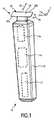
図1は、簡略な斜視図において、毛切断器具10、具体的には、電気毛切断器具10の例示的な実施態様を概略的に例示している。切断器具10は、ハウジング12と、ハウジング内に破線ブロック14によって示すモータと、ハウジング12内に破線ブロック16によって示す駆動機構又はドライブトレーンとを含んでよい。モータ14に給電するために、切断器具10の少なくとも幾つかの実施態様では、例えば、再充電可能なバッテリ、交換可能なバッテリ等のような、ハウジング12内に破線ブロック17によって示す電気バッテリが設けられてよい。しかしながら、幾つかの実施態様において、切断器具10は、電源を接続する電力ケーブルを更に備えてよい。(内部)電気バッテリ17に加えて或いは(内部)電気バッテリ17の代わりに、電源コネクタが設けられてよい。 FIG. 1 schematically illustrates, in a simplified perspective view, an exemplary embodiment of a hair-cutting
切断器具10は、切断ヘッド18を更に含んでよい。切断ヘッド18で、ブレードセット20が毛切断器具10に取り付けられてよい。ブレードセット20は、切断運動を可能にするために、駆動機構又はドライブトレーン16を介してモータ14によって駆動させられてよい。切断運動は、一般的に、例えば、図3により詳細に示し且つ例示し、そして、以下に記載し且つ議論するように、静止ブレード22と可動ブレード24との間の相対運動として考えられてよい。一般的に、使用者は、切断器具10に握り、保持し、且つ移動方向を通じて切断器具10を手動で案内して、毛を切断する。切断器具10は、手で案内され且つ手で操作される電動デバイスとして考えられてよい。更に、切断ヘッド18、より具体的には、ブレードセット20を、旋回可能な方法において切断器具10のハウジング12に接続し得る。図1に参照番号26によって示す湾曲した両矢印を参照のこと。幾つかの実施態様において、切断器具10、又は、より具体的には、ブレードセット20を含む切断ヘッド18を、皮膚に沿って動かして、皮膚で成長する毛を切断し得る。皮膚の近くで毛を切断するときには、基本的に、皮膚の高さ(level)で毛を切断する或いは剪断することを目標としてシェービング作業を行い得る。しかしながら、クリッピング(又はトリミング)作業も想定してよく、ブレードセット20を含む切断ヘッド18は、皮膚に対して所望の距離で、ある経路に沿って進められる。 The cutting
毛を通じて案内されるとき、ブレードセット20を含む切断器具10を、典型的には、図1に参照番号28によって示す一般的な移動方向に沿って動かし得る。この関係において、毛切断器具10が、典型的には、手動で案内され且つ動かされることを考慮すると、移動方向は、必ずしも、毛切断器具10及びブレードセット20を備えるその切断ヘッド18の向きに対して一定の定義(definition)及び関係(relation)を有する精密な幾何学的基準として解釈されなければならないわけではないことは、述べるに値する。即ち、皮膚にある切断されるべき毛に対する毛切断器具10の全体的な向きは、幾分不安定なものとして解釈されてよい。しかしながら、例示の目的のために、(仮想)移動方向28は、以下において毛切断器具10の構造的な構成を記述するための手段としての機能を果たすことがある座標系の主中央平面と平行(又は概ね平行)であると適正に想定されてよい。 When guided through the bristles, the cutting
参照の容易さのために、ここにおける幾つかの図面中に座標系を示している。一例として、デカルト座標系X−Y−Zを図1に示している。それぞれの座標系の軸Xは、この開示の目的のために、長さと概ね関連付けられる概ね長さ方向に延びる。座標系の軸Yは、この開示の目的のために、幅と関連付けられる横(又は横断)方向に延びる。座標系の軸Zは、例示の目的のために、少なくとも幾つかの実施態様において、概ね垂直な方向と呼ぶ、高さ(垂直)方向に延びる。毛切断器具10の特徴的な構成及び/又は実施態様への座標系X−Y−Zの関連付けは、主として例示の目的のために提供されており、限定的な方法において解釈されてならないことは、言うまでもない。当業者は、異なる向きを含む、代替的な実施態様、それぞれの図面及び例示に直面するとき、ここにおいて提供する座標系を容易に変換し且つ/或いは移転してよいことが、理解されなければならない。本開示の目的のために、座標系X−Y−Zが、ブレードセット20を含む切断ヘッド18の主方向及び向きと概ね整列させられることは、更に述べるに値する。 For ease of reference, coordinate systems are shown in some of the figures herein. As an example, a Cartesian coordinate system XYZ is shown in FIG. The axis X of each coordinate system extends for the purposes of this disclosure in a generally longitudinal direction that is generally associated with a length. The axis Y of the coordinate system extends in the lateral (or transverse) direction associated with the width for the purposes of this disclosure. The axis Z of the coordinate system extends in a height (vertical) direction, which in at least some embodiments is referred to as a generally vertical direction for purposes of illustration. The association of the coordinate system XYZ to the characteristic configuration and/or embodiment of the hair-cutting
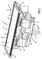
図2は、図1に示す毛切断器具に取り付けてよい切断ヘッド18の例示的な実施態様の斜視頂面図を例示している。切断ヘッド18は、既に上述したブレードセット20を備える。ブレードセット20は、静止ブレード22と、(図2では隠されている)可動カッタブレード24を含む。この関係で、図3及び図4に示すブレードセット20の分解図を更に参照する。静止ブレード22及び可動カッタブレード24は、互いに対して動くように構成され、それにより、それぞれの切断エッジで毛を切断する。 FIG. 2 illustrates a perspective top view of an exemplary embodiment of a cutting
静止ブレード22は、皮膚に面する表面と考えられてよい頂面32を更に含む。典型的には、シェービングデバイスとしての動作中、毛切断器具10は、頂面32が皮膚に対して基本的に平行であるか或いは僅かに傾斜させられた方法において方向付けられる。しかしながら、頂面32が必ずしも皮膚と平行でない或いは少なくとも実質的に平行でない代替的な動作モードも想定されてよい。例えば、毛切断器具10は、あごひげスタイリングのために、或いは、より一般的には、ヘアスタイリングのために更に用いられてよい。ヘアスタイリングは、異なって処置される使用者の毛部分又はあごひげ部分の間のかなり鋭利なエッジ又は移行部の処理を目標とすることがある。一例として、ヘアスタイリングは、もみあげの精密な成形(shaping)又は顔毛の更なる異なるパッチ(distinct patch)を含んでよい。結果的に、スタイリングモードにおいて用いられるとき、頂面32及び目下のところ処置されるべき皮膚部分は、ある角度に、具体的には、互いに対して実質的に垂直に、配置される。 The
しかしながら、主として例示の目的のために、以下、頂面32及び毛切断器具10の類似に方向付けられる部分及びコンポーネント(構成部品)は、皮膚に面するコンポーネント及び部分と考えられてよい。結果的に、反対の方法において方向付けられる要素及び部分は、開示の目的のために、以下、後方に方向付けられる要素及び部分と考えられてよく、或いは、むしろ皮膚から見て外方を向く要素及び部分と考えられてよい。 However, primarily for purposes of illustration, the
既に上述したように、静止ブレード22は、少なくとも1つの歯付き前縁30を定めてよい。図2に示すように、静止ブレードは、縦方向Xにおいて互いにオフセットされる第1の前縁30a及び第2の前縁30bを定めてよい。少なくとも1つの歯付き前縁30a,30bは、横方向Yに概ね延びてよい。頂面32は、縦方向X及び横方向Yによって定められる平面と概ね平行な表面と考えられてよい。少なくとも1つの歯付き前縁30で、静止ブレード22の複数の歯36が設けられてよい。歯36は、それぞれの歯スロットと交互してよい。歯スロットは、歯36の間に間隙を定めてよい。毛切断器具10が移動方向28において毛を通じて動かされるとき(図1)、毛が間隙に入る。 As already mentioned above, the
静止ブレード22は、例えば、金属−プラスチック複合コンポーネントとして構成されてよい。換言すれば、静止ブレード22は、メタルコンポーネント40を提供するステップ(図3及び図4も参照のこと)と、メタルコンポーネント40及びプラスチックコンポーネント38を結合するステップを含む、プラスチックコンポーネント38を形成するステップ(forming)、又は、より正確には、鋳造するステップ(molding)とを含む、マルチステップ製造方法から得られてよい。これは、具体的には、インサート成形(insert-molding)プロセス、アウトサート成形(outsert-molding)プロセス、又はオーバーモールド(overmolding)プロセスによって、静止ブレード22を形成することを含んでよい。一般的に、静止ブレード22は、2コンポーネント静止ブレード22と考えられてよい。しかしながら、静止ブレード22は、一貫生産プロセスによって形成されるのが好ましいので、静止ブレード22を形成するときに、基本的に従来的なステップは必要とされない。むしろ、一貫生産プロセスは、正味形状(net-shape)生産ステップ、又は、少なくとも、近正味形状(near-net-shape)生産プロセスを含んでよい。一例として、プラスチックコンポーネント38をメタルコンポーネント40に結合することも含んでよい、プラスチックコンポーネント38を鋳造するステップは、静止ブレード22の近正味形状又は正味形状構成を定めてよい。メタルコンポーネント40がシートメタルで作られるのが特に好ましい。プラスチックコンポーネント38が射出成形可能なプラスチック材料で作られるのが特に好ましい。 The
異なるコンポーネントから静止ブレード22を形成すること、特に、静止ブレード22を一体形成することは、動作中に高い荷重に耐えなければならない静止ブレードの部分がそれぞれの高強度材料(例えば、金属材料)で形成されてよいのに対し、動作中に大きな荷重に概ね晒されない静止ブレードの部分が異なる材料で形成されてよいという利点を更に有することがあり、それは製造コストを有意に減少させる。静止ブレード22をプラスチック−金属複合部品として形成することは、使用者が皮膚接触をより快適であると感じることがあるという利点を更に有することがある。特に、プラスチックコンポーネント38は、メタルコンポーネント40と比較するとき、大いに減少させられた熱伝導率を示すことがある。結果的に、毛を切断するときに使用者が感じる熱放射は減少させられることがある。従来的な毛切断器具において、熱生成は、切断性能を向上させることについての大きな障害と考えられることがある。熱生成は、毛切断器具のパワー及び/又は切断速度を基本的に制限する。基本的に熱絶縁する材料(例えば、プラスチック材料を追加することによって、熱生成スポット(例えば、切断エッジ)から使用者の皮膚への熱移転は、大いに減少させられることがある。これは、特に、プラスチック材料で形成されることがある静止ブレード22の歯36の先端に当て嵌まる。 Forming the
一体成形される金属−プラスチック複合部品として静止ブレード22を形成することは、更なる機能が静止ブレード22の設計中に統合されることがあるという利点を更に有することがある。換言すれば、静止ブレード22は、追加的なコンポーネントを静止ブレードに付着させ或いは取り付けることを必要とせずに、強化された機能性をもたらすことがある。 Forming the
一例として、静止ブレード22のプラスチックコンポーネント38は、いわゆる側面保護体と考えられてもよい横方向保護要素42を備えてよい。横方向保護要素42は、静止ブレード22の横方向端を覆ってよい。図3、4及び10も参照のこと。結果的に、メタルコンポーネント40の比較的鋭利な横方向端での直接的な皮膚接触を防止し得る。これは特に有益なことがある。何故ならば、静止ブレード22のメタルコンポーネント40は、シェービングのときに皮膚に近接して毛を切断するのを可能にするよう、比較的薄いからである。しかしながら、同時に、メタルコンポーネント40の比較的薄い構成は、シェービング中に皮膚表面の上をスライドするときに皮膚に炎症(irritation)を引き起こすことがある。特にメタルコンポーネント40の皮膚接触部分は実際に薄いので、比較的鋭利なエッジが残り、メタルコンポーネント40及び静止ブレード22が実際により薄ければ薄いほど、皮膚炎症の危険はより高く、皮膚切断の危険さえもより高い。従って、少なくとも幾つかの実施態様では、メタルコンポーネント40の横方向側面を遮蔽することが好ましい。横方向保護要素42は、垂直方向又は高さ方向Zにおいて頂面から突出してよい。少なくとも1つの横方向保護要素42が、プラスチックコンポーネント38の一体部品として形成されてよい。 As an example, the
静止ブレード22は、取付け要素48を更に備えてよい。取付け要素48は、プラスチックコンポーネント38に配置されてよく、具体的には、プラスチックコンポーネント38と一体的に構成されてよい。図3、4及び10も参照のこと。取付け要素48は、取付け突起、具体的には、スナップ留め取付け要素を含んでよい。取付け要素48は、リンケージ機構50でそれぞれの取付け要素と協働するように、構成されてよい。更なる別個の取付け部材を用いずにブレードセット20をリンケージ機構50に取り付け得るのが特に好ましい。 The
リンケージ機構50(図2を参照のこと)は、ブレードセット20と毛切断器具10のハウジング12とを接続してよい。リンケージ機構50は、毛を通じて案内されるときに、ブレードセット20が動作中にスイベルし或いは旋回してよいよう、構成されてよい。リンケージ機構50は、ブレードセット20に輪郭追従能力をもたらすことがある。幾つかの実施態様において、リンケージ機構50は、4バー機構として構成される。これはブレードセット20の明確なスイベル特性を可能にすることがある。リンケージ機構50は、ブレードセット20のための仮想の旋回軸を定めてよい。 The linkage mechanism 50 (see FIG. 2) may connect the blade set 20 and the
図2は、偏心連結機構58を更に例示している。偏心連結機構58は、毛切断器具10の駆動機構又はドライブトレーンの部分と考えられてよい。偏心連結機構58は、回転駆動運動(図2に参照番号64によって示す湾曲矢印を参照のこと)を静止ブレード22に対する可動ブレード24の往復運動に変換するように、構成されてよい。これに関しては、図14(参照番号126によって示す両矢印)も参照のこと。偏心連結機構58は、軸62についての回転のために駆動させられるように構成されるドライブシャフト60を含んでよい。ブレードセット20に面するドライブシャフト60の前方端に、偏心部分66が設けられてよい。偏心部分66は、(中心)軸62からオフセットされる円筒形部分を含んでよい。ドライブシャフト60の回転後、偏心部分66は、軸62の周りで回転してよい。偏心部分66は、可動ブレード24に取り付けられてよい伝動部材70と係合するように配置される。 FIG. 2 further illustrates the
図3及び図4の分解図に示す実施態様を更に参照して、伝動部材70を更に詳細に記載する。伝動部材70は、ドライブシャフト60の偏心部分66によって係合されるように構成されてよい往復動要素72を含んでよい。図2も参照のこと。結果的に、往復動要素72は、ドライブシャフト60によって往復式に駆動させられてよい。伝動部材70は、可動カッタブレード24と、特にその主要部分78と接触するように構成されてよい、コネクタブリッジ74を更に含んでよい。一例として、コネクタブリッジ74は、可動カッタブレード24に結合されてよい。結合は、鑞接、溶接、及び類似のプロセスを含んでよい。往復動要素72は、コネクタブリッジ74に結合されてよい。この目的を達成するために、インサート成形プロセス、アウトサート成形プロセス、及び/又はオーバーモールドプロセスが利用されてよい。この脈絡において、可動カッタブレード24が、可動カッタブレード24の対向する横方向端に、少なくとも1つの横方向端スロット98、好ましくは二対の横方向端スロット98を含むのが、より一層好ましいことがある。少なくとも1つの横方向端スロット98は、基本的に横方向に延びるスロット又はノッチとして配置されてよい。少なくとも1つの横方向端スロットは、可動カッタブレード24へのコネクタブリッジ74の取付けに起因することがある、ひずみ、特に熱で誘発される溶接ひずみを補償するよう、設けられてよい。この目的を達成するために、少なくとも1つの横方向端スロット98は、それぞれの結合スポット又は溶接スポットの近傍に配置されてよい。好ましくは、一対の横方向端スロット98がそれぞれの結合スポット又は溶接スポットに近接して配置され、スポットは横方向端スロット98の間に配置される。 With further reference to the embodiment shown in the exploded view of FIGS. 3 and 4, the
しかしながら、少なくとも幾つかの実施態様において、コネクタブリッジ74又は伝動部材70の類似の接続要素は、むしろ可動カッタブレード24に取り付けられてよい。ここにおいて用いるとき、取り付けることは、差し込むこと、押し込むこと、圧入すること、又は類似の取付け作業を含んでよい。伝動部材70は、コネクタブリッジ74に配置されてよい取付け要素76を更に含んでよい。取付け要素76で、往復動要素72は、コネクタブリッジ74に取り付けられてよい。一例として、コネクタブリッジ74及び取付け要素76は、金属部品として構成されてよい。一例として、往復動要素72は、プラスチック部品として構成されてよい。例えば、取付け要素76は、コネクタブリッジ74で往復動要素72を固定するためのスナップ留め要素を含んでよい。しかしながら、代替において、往復動要素76がコネクタブリッジ74にしっかり固定されるときに、取付け要素76は、往復動要素72のための固定要素と考えられてよい。 However, in at least some embodiments, the
この点において、伝動部材70が、横方向往復式駆動運動を可動カッタブレード24に伝えるために主として配置されてよいことは、述べるに値する。しかしながら、伝動部材70は、ブレードセット20で可動カッタブレード24のための損失防止デバイスとしての機能を果たすように、更に配置されてよい。 At this point, it is worth mentioning that the
図3は、中間壁部分44を実施するブレードセット20の実施態様を更に例示している。図4は、中間壁部分44の代替的な実施態様を実施するブレードセット20の実施態様を更に例示している。組立て状態において、中間壁部分44は、ブレードセット20の静止ブレード22に、特に、その第1の壁部分100に固定的に取り付けられてよい。図7及び図8も参照のこと。より正確には、中間壁部分44は、組立て状態において、メタルコンポーネント40に固定的に取り付けられてよい。図3に示すようなブレードセット20の実施態様と類似する実施態様を通じる断面図が、図15に例示されている。図4に示すようなブレードセット20の実施態様と類似する実施態様を通じる断面図が、図16に例示されている。 FIG. 3 further illustrates an embodiment of blade set 20 that implements
図3、7及び15に見ることができるように、中間壁部分44は、ガイド部分52(guide portion)を含んでよく、可動カッタブレード24にあるそれぞれのガイド開口46と協働するように更に構成されてよい。この目的を達成するために、中間壁部分44は、ガイド部分52に設けられるのが好ましい接触要素56を含んでよい。一例として、二対の対向する接触要素56が、ガイド部分52の対向する横方向端に配置される。接触要素56は、ガイド開口46に設けられる少なくとも1つの内側ガイド面57と接触するように構成される。接触要素56を接触タブと呼ぶことがある。少なくとも1つの内側ガイド面57を横方向に延びるガイド表面と呼ぶことがある。一般的に、中間壁部分44は、静止ブレード22での可動カッタブレード24の縦位置を定めるように構成されてよい。 As can be seen in FIGS. 3, 7 and 15, the
これに関して、図11を更に参照する。図11は、可動カッタブレード24及び中間壁部分44が噛み合わされている或いは対にさせられている構成を示している。可動カッタブレード24が中間壁部分44に対して少なくとも僅かに横方向に移動可能であることを更に見ることができる。参照番号126によって示す両矢印を参照のこと。縦方向(X方向)に関して、中間壁部分44と可動カッタブレード24との間の緊密な隙間嵌め(clearance fit)が望まれることがある。 In this regard, further reference is made to FIG. FIG. 11 shows a configuration in which the
図3、7及び15を更に参照して、プラスチックコンポーネント38及びメタルコンポーネント40との中間壁部分44の協働を更に詳細に説明する。一般的に、プラスチックコンポーネント38は、第2の壁部分102の少なくとも実質的な部分を形成してよい。一般的に、メタルコンポーネント40は、第1の壁部分100の少なくとも実質的な部分を形成してよい。故に、中間壁部分44は、基本的に、第1の壁部分100から第2の壁部分102に延びてよく、具体的には、メタルコンポーネント40からプラスチックコンポーネント38に延びてよい。上述のように、中間壁部分44が、取付け状態において、第1の壁部分100に固定的に取り付けられ、第2の壁部分102と当接するのが、好ましいことがある。中間壁部分44が第2の壁部分102に結合されることは必ずしも必要とされない。しかしながら、中間壁部分44が、取付け状態において、少なくとも部分的に付勢される方法において、第1の壁部分100と第2の壁部分102との間に配置されることが好ましい。 With further reference to FIGS. 3, 7 and 15, the cooperation of the
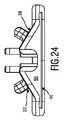
図4、8及び16に見ることができるように、代替的な構成において、静止ブレード22は、ガイド部分52と、保持部分54とを含む、中間壁部分44を含んでよい。保持部分54は、縦方向(X方向)において、少なくとも僅かにガイド部分52より上に突出してよい。結果的に、中間壁部分44は、可動カッタブレード24の垂直位置(Z位置)を更に定めてよい。図16を特に参照のこと。 In an alternative configuration, as can be seen in FIGS. 4, 8 and 16, the
一般的に、中間壁部分44及びメタルコンポーネント40は協働して、静止ブレード22で可動カッタブレード24を取外し不能な方法において固定してよい。これは図3に示すような実施態様によって並びに図4に示すような実施態様によって達成されることがある。 Generally, the
図3及び図4は、静止ブレード22のプラスチックコンポーネント38及びメタルコンポーネント40を分解状態において更に例示している。この関係において、静止ブレード22は一体成形されるのが好ましいので、そのプラスチックコンポーネント38は、典型的には、例えば、隔離された特異な状態において、存在しない。むしろ、少なくとも幾つかの実施態様において、プラスチックコンポーネント38を形成することは、プラスチックコンポーネント38をメタルコンポーネント40にしっかり結合することを必要的に含むことがある。中間壁部分44は、後の段階で、それに取り付けられてよい。 3 and 4 further illustrate the
静止ブレード22は、可動カッタブレード24を挿入してよい、少なくとも1つの横方向開口68を含んでよい。結果的に、可動カッタブレードは、横方向Yにおいて挿入されてよい。しかしながら、少なくとも幾つかの実施態様において、伝動部材70は、基本的に垂直方向Zに沿って、可動カッタブレード24に対して移動させられてよい。従って、可動カッタブレード24及び伝動部材70を噛み合わせることは、第1に、静止ブレード22の横方向開口68を通じて可動カッタブレード24を挿入すること、第2に、可動カッタブレード24が静止ブレード22内に配置されるときに、可動カッタブレード24に接続されるよう、伝動部材を垂直方向Zに沿って静止ブレード22に送る或いは移動させることを含んでよい。 The
一般的に、可動カッタブレード24は、主要部分78に隣接する少なくとも1つの歯付き前縁80を含んでよい。具体的には、可動カッタブレード24は、第1の前縁80aと、第1の前縁80aから長手方向にオフセットされる第2の苗縁80bとを含んでよい。少なくとも1つの前縁80で、それぞれの歯スロットと交互する、複数の歯82が形成されてよい。歯82の各々は、具体的には、それらの横方向フランクに、それぞれの切断エッジ84を備えてよい。可動カッタブレード24の少なくとも1つの歯付き前縁80は、可動カッタブレード24と静止ブレード22との間の相対的な運動が誘発されるときに、静止ブレード22のそれぞれの歯付き前縁30と協働するように、配置されてよい。結果的に、静止ブレード22の歯36及び可動カッタブレード24の歯82は協働して、毛を切断してよい。 Generally, the
図5乃至10を特に参照して、静止ブレード22の例示的な実施態様の構造及び構成を更に詳説し且つ例示する。図5は、静止ブレード22の部分頂面図であり、メタルコンポーネント40の隠された部分(図6も参照のこと)が、例示的な目的のために示されている。静止ブレード22の歯36に、先端86が形成されてよい。先端86は、プラスチックコンポーネント38によって主に形成されてよい。しかしながら、歯36の実質的な部分は、メタルコンポーネント40によって形成されてよい。図6に最良に見ることができるように、メタルコンポーネント40は、歯36の実質的な部分を形成してよい、いわゆる歯ステム部分88を含んでよい。歯ステム部分88は、可動カッタブレード24の歯82の切断エッジ84と協働するように構成される、それぞれの切断エッジ94を備えてよい。歯ステム部分88の長手方向端に、固定要素90が配置されてよい。固定要素90は、メタルコンポーネント40及びプラスチックコンポーネント38の接続を更に強化することがある、確動嵌め(positive fit)接触要素と考えられてよい。 With particular reference to FIGS. 5-10, the structure and construction of an exemplary embodiment of
一例として、固定要素90は、アンダーカット又は凹み部分を備えてよい。結果的に、固定要素90は、棘付き固定要素と考えられてよい。好ましくは、固定要素90と接触するプラスチックコンポーネント38のそれぞれの部分は、損傷されなければ或いは破壊されさえしなければ、メタルコンポーネント40から切り離されない或いは解放されないことがある。換言すれば、プラスチックコンポーネント38は、メタルコンポーネント40と切離し不能にリンクされてよい。図6に示すように、固定要素90は、凹部又は孔92を備えてよい。孔92は、例えば、スロット孔と考えられてよい。プラスチックコンポーネント38を鋳造するとき、プラスチック材料が孔92に入ってよい。図7及び図9に最良に見ることができるように、プラスチック材料は、両方の(垂直)側から、即ち、頂側及び底側から、固定要素90の凹部又は孔92を充填してよい。結果的に、固定要素90は、プラスチックコンポーネント38によって完全に覆われてよい。固定要素90に近接して、先端86が形成されてよい。プラスチックコンポーネント38から先端86を形成することは、前縁30の前方端が、エッジを軟らかくするために丸められてよい或いは面取りされてよい比較的軟らかい材料で形成されるという利点を更に有することがある。結果的に、前縁30の前方端で使用者の皮膚に触れることは、典型的には、皮膚炎症又は類似の有害な影響を引き起こすものとして経験されない。また、高温スポットが、先端36で防止されることがある。何故ならば、プラスチックコンポーネント38は、典型的には、メタルコンポーネント40と比べて、比較的低い熱伝導係数を備えるからである。 As an example, the
図7、8及び9の断面図に最良に見ることができるように、前縁30の前方端にある歯36の先端86のエッジは、有意に丸められてよい。更に見ることができるように、歯36の領域における頂面32でのメタルコンポーネント40とプラスチックコンポーネント38との間の移行は、実質的に継ぎ目なし(シームレス)又は無段(ステップレス)であってよい。これに関しては、図10を更に参照のこと。固定要素90の上側(皮膚に面する側)が頂面32からオフセットされるように、固定要素90を形作ることは、有利なことがある。結果的に、固定要素90の皮膚に面する側も、プラスチックコンポーネント38によって覆われてよい。図9も参照のこと。1つの例示的な実施態様において、固定要素90は、頂面32に対して傾斜させられてよい。固定要素90は、歯ステム部分88に対して、ある角度α(アルファ)に配置されてよい。固定要素90が頂面32に対して後方に曲げられるのが更に好ましいことがある。少なくとも幾つかの実施態様において、固定要素90は、歯ステム部分88よりも薄くてよい。これは鋳造時にプラスチックコンポーネント38によって充填されてよい空間を更に拡大することがある。 As best seen in the cross-sectional views of FIGS. 7, 8 and 9, the edges of the
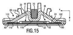
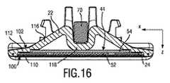
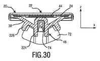
図7を更に参照して、静止ブレード22を更に詳細に記載する。静止ブレード22は、可動カッタブレード24のためのガイドスロット96を定め且つ取り囲む。この目的を達成するために、静止ブレード22は、第1の壁部分100と、第2の壁部分102とを含んでよい。この開示の目的のために、第1の壁部分100は、皮膚に面する壁部分と考えられてよい。これは特にブレードセット20がシェービングのために用いられるときに当て嵌まる。結果的に、第2の壁部分102は、皮膚から見て外方を向く壁部分と考えられてよい。換言すれば、第1の壁部分100は、頂壁部分と考えられてもよい。第2の壁部分102は、底壁部分と考えられてもよい。 Still referring to FIG. 7,
主として例示の目的のために、図7及び図8は、中間壁部分44の僅かに外れた実施態様を例示している。図3及び図4も参照のこと。図7によれば、中間壁部分44は、可動カッタブレード24のそれぞれのガイド開口46に適合させられるガイド部分52で主に構成される。図8によれば、中間壁部分44は、可動カッタブレード24のそれぞれのガイド開口46に適合させられるガイド部分52と、保持部分54とを含む。図7に見ることができるように、中間壁部分44は、静止ブレード22の第1の壁部分100と第2の壁部分102との間の中央オフセットlcoを設定してよい。これは有利である。何故ならば、結果的に、歯36での第1の壁部分100と第2の壁部分102との間の所望の間隙が、このようにして正確に定められることがあるからである。Mainly for purposes of illustration, FIGS. 7 and 8 illustrate a slightly offset embodiment of the
故に、可動カッタブレード24は、正確且つ精密な方法においてガイドスロット94内に受け入れられることがある。図15に見ることができるように、可動カッタブレード24は、高さ伸張ltを含む。それぞれの所望の間隙は、中央オフセットlcoによって決定されてよい。結果的に、第2の壁部分102、又は、より正確には、プラスチックコンポーネント38が、典型的には、絶対的に厳格な公差で製造され得ないとしても、静止ブレード22での可動カッタブレード24の所望の適合が保証されることがある。更に、中央オフセットlcoを精密に設定することによって、収縮効果及び反りが、少なくともある程度まで補償されることがある。Therefore, the
図8に見ることができるように、中間壁部分44は、取り付けられるべき可動カッタブレード24のための結果として間隙lclを更に定めてよい。これはガイド部分52が可動カッタブレード24の高さltに十分に適合させられる(例えば、可動カッタブレード24の高さltよりも僅かに大きい)ときに又は中間壁部分44がガイド部分52を越えて少なくとも部分的に突出する保持部分54を更に備えるときに達成されることがある。結果的に、第2の壁部分102及び/又はプラスチックコンポーネント38は、ある程度まで可動カッタブレード24のための所望の間隙又は隙間を定めることから解放される。As can be seen in FIG. 8, the
第1の壁部分100及び第2の壁部分102は、静止ブレード22の歯36を共同で定めてよい。歯36は、可動カッタブレード24のための、具体的には、少なくとも1つの歯付き前縁80に配置される可動カッタブレードの歯82のための、スロット又は間隙を含んでよい。上述のように、少なくとも第1の壁部分100の実質的な部分は、メタルコンポーネント40によって形成されてよい。少なくとも第2の壁部分102の実質的な部分は、プラスチックコンポーネント38によって形成されてよい。図7に例示する例示的な実施態様で、第2の壁部分102は、プラスチックコンポーネント38によって全体的に形成される。むしろ、第1の壁部分100は、プラスチックコンポーネント38及びメタルコンポーネント40によって共同で形成される。これは特に前縁30で当て嵌まる。第1の壁部分100は、そのそれぞれの歯部分で、プラスチックコンポーネント38がメタルコンポーネント40に結合される結合部分106を含んでよい。結合部分106は、メタルコンポーネント40の固定要素90を含んでよく、プラスチックコンポーネント38のプラスチック材料が固定要素90を覆う。 The
図7及び図9は、歯36を通じる断面を例示している。図5中の線VIII−VIIIも参照のこと。対照的に、図8は、歯スロットを通じる断面を例示している。図5中の線VII−VIIを参照のこと。図7及び図8に見ることができるように、第1の壁部分100及び第2の壁部分102は、歯36を含む前縁30を共同で形成してよい。第1の壁部分100及び第2の壁部分102は、それぞれの歯36の基本的にU形状の横断面を共同で定めてよい。第1の壁部分100は、U形状の形態の第1の脚110を定めてよい。第2の壁部分102は、U形状の形態の第2の脚112を定めてよい。第1の脚110及び第2の脚112は、歯36の先端86で接続されてよい。第1の脚110と第2の脚112との間には、可動カッタブレード24のためのスロット又は間隙が設けられてよい。 7 and 9 illustrate cross-sections through the
図7に更に見ることができるように、第1の壁部分100は、静止ブレード22の第2の壁部分102よりも有意に薄くてよい。結果的に、皮膚に面する第1の壁部分100で、皮膚に極めて近接して毛を切り得る。従って、第1の壁部分100の厚さ、特に、メタルコンポーネント40の厚さを減少させることが望ましい。一例として、特にはステム部分88での、メタルコンポーネント40の厚さltm(図8を参照のこと)は、約0.08〜0.15mmの範囲内にあってよい。結果的に、そのような第1の壁部分100は、相当に小さい強度及び剛性(rigidity)を示すことがある。従って、第2の壁部分102を追加することによって、第1の壁部分100を支える或いは強化することが有益である。第2の壁部分102の厚さは、最小達成可能な切断長(例えば、皮膚で残っている毛の長さ)に基本的に影響を及ぼさないので、特にそれぞれの前縁30での、第2の壁部分102の厚さは、特にメタルコンポーネント40の厚さは、第1の壁部分100の厚さltmよりも有意に大きくてよい。これは十分な強度及び安定性を備える静止ブレード22をもたらすことがある。図7に更に見ることができるように、第1の壁部分100及び第2の壁部分102は、少なくともそれらの横方向延伸に沿って、閉塞プロファイルを基本的に形成してよい。この関係において、図12及び図13も参照のこと。これは静止ブレード22が第1及び第2の前縁30a,30bを備えるときに特に当て嵌まることがある。結果的に、静止ブレード22の剛性(stiffness)、特に曲げ応力又は捩り応力に対する剛性は、更に増大させられることがある。As can be further seen in FIG. 7, the
1つの例示的な実施態様において、第2の壁部分102は、それぞれの前縁30にある第2の脚112に近接して、傾斜部分116を含んでよい。静止ブレード22が、垂直方向Z及び横方向Yによって定められる中央平面に対して基本的に対称的に形作られると想定すると、第2の壁部分102は、傾斜部分116に近接して中央部分118を更に含んでよい。結果的に、中央部分118は、第1の傾斜部分116と第2の傾斜部分116との間に介装されてよい。第1の傾斜部分116は、第1の前縁30aにあるそれぞれの第2の脚112に近接して位置付けられてよい。第2の傾斜部分116は、第2の前縁30bにあるそれぞれの第2の脚112に近接して位置付けられてよい。図7に見ることができるように、第2の壁部分102は、傾斜部分116及び中央部分118によって主に定められる、基本的にM形状の断面を含んでよい。 In one exemplary embodiment, the
図12及び図13を更に参照して、静止ブレード22のプラスチックコンポーネント38の例示的な実施態様の形状及び構成を更に詳細に記載する。図12に見ることができるように、傾斜部分116a,116bは、基本的に、プラスチックコンポーネント38の全(横方向)長さに亘って延在してよい。前縁30a,30bは、プラスチックコンポーネント38の対向する(横方向)端に配置される第1の横方向保護要素42と第2の横方向保護要素42との間に概ね延在してよい。ガイドスロット96の底側を基本的に定める図9に示すプラスチックコンポーネント38の凹み部分は、メタルコンポーネント40によって概ね覆われる。図2を参照のこと。 12 and 13, the shape and construction of an exemplary embodiment of the
図13に見ることができるように、傾斜部分116a,116bの間の中央部分118は、プラスチックコンポーネント38の全(横方向)長さの実質的な部分に沿って概ね延在してよい。しかしながら、中央部分118に並んで、少なくとも1つの開口スロット120が設けられてよい。図12及び図13に示す例示的な実施態様によれば、中央部分118は、第1の開口スロット120aと第2の開口スロット120bとの間に配置されてよい。開口スロット120a,120bは、少なくとも1つの開口を定めてよく、組立て状態において、伝動部材70は、少なくとも1つの開口を通じて、可動カッタブレード24に接触することがある。図12に最良に見ることができるように、プラスチックコンポーネント38は、コネクタブリッジ74、結果的に、コネクタブリッジに接続される可動カッタブレード24を案内するように構成されてよい、少なくとも1つのガイド要素122、具体的には、複数のガイド要素122を更に含んでよい。1つの例示的な実施態様において、複数のガイド要素122は、対において配置されてよく、それぞれの対は、中央部分118の横方向にオフセットさせられた端に配置される。ガイド要素122は、基本的に垂直に延びる凸状に形作られたプロファイルとして構成されてよい。ガイド要素122は、可動カッタブレード24及び伝動部材70の長手位置を定めてよい。しかしながら、可動カッタブレード24の長手位置を定めるように構成されてよい中間壁部分44を実施する(複数の)実施態様との関係において、ガイド要素122は、互いにから更に離間させられてよい。結果的に、伝動部材70及びそのコネクタブリッジ74は、ガイド要素122と恒久的な案内接触しなくてよい。むしろ、ガイド要素122は、粗い長手方向の向きをもたらしてよいのに対し、中間壁部分44は、可動カッタブレード24の正確な長手方向の位置付けを保証してよい。ブレードセット20の最終的な組立て状態では、ガイド要素122とコネクタブリッジ74との間に十分な長手方向の隙間があってよい。結果的に、可動カッタブレード24及び静止ブレード22の過剰に決定される組立てが回避されることがある。 As can be seen in FIG. 13, the
これに関して、中央部分118及び特に伝動部材70のための少なくとも1つの開口スロット120が代替的な実施態様において異なって構成されてよいことは、更に述べるに値する。一例として、1つの実施態様において、中央部分118は、コネクタブリッジ74を可動カッタブレード24と接触させてよい単一の開口スロット120によって中断されてよい。従って、伝動部材70のコネクタブリッジ74は、図3に見ることができるように、横方向Yにおいて互いに相当に離間させられる可動カッタブレード24のための2つの接触スポットを必ずしも含まなければならないわけでないことが強調される。むしろ、コネクタブリッジ74は、(横方向)中央部分で可動カッタブレード24と接触してもよい。 In this regard, it is worth further mentioning that the
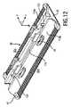
図14、15及び16を特に参照して、可動カッタブレード24と適合される静止ブレード22を含むブレードセット20を更に詳細に記載する。図14は、ブレードセット20の部分頂面図であり、可動カッタブレード24の隠された輪郭が破線によって示されている。図15は、図3に示す構成の断面図であり、断面は、静止ブレード22にある歯36と、可動カッタブレード24にある歯スロットとを含む。図14中の線XV−XVを参照のこと。図16は、図4に示す構成の断面図であり、断面は、静止ブレード22にある歯36と、可動カッタブレードにある歯スロットとを含む。図14中の線XVI−XVIを参照のこと。結果的に、図15及び16は、従って、僅かに異なる実施態様の同様に方向付けられた断面(図14中の同じ線)を基本的に例示している。可動カッタブレード24を往復式に静止ブレード22に対して駆動させ得る。図14中に126によって示す両矢印を参照のこと。静止ブレード22及び可動カッタブレード24の相対的な運動後、それぞれの歯36及び82は協働して、それぞれの歯スロットに入る毛を切断する。 With particular reference to FIGS. 14, 15 and 16, blade set 20 will be described in further detail including
駆動運動を可動カッタブレード24に伝えるように基本的に構成される伝動部材70は、静止ブレード22を通じて、具体的には、静止ブレード22の中央部分118と関連付けられる少なくとも1つの開口スロット120を通じて、延在してよい。図13を参照のこと。図16は、伝動部材、結果的に、可動カッタブレード24を案内してよい、一対のガイド要素122を更に示している。幾つかの実施態様において、ガイド要素122は、静止ブレード22での可動カッタブレード24及び伝動部材70の長手方向位置を定めてよい。幾つかの実施態様において、静止ブレード22での可動カッタブレード24の長手方向位置は、静止ブレード22の中間壁部分44及び可動カッタブレード24のガイド開口46の協働によって定められてよい。 The
少なくとも幾つかの実施態様において、可動カッタブレード24は、明確な方法においてガイドスロット96内に配置されるのが特に好ましい。可動カッタブレード24を、第1の壁部分100と緊密に接触して、その所望の位置に維持するために、更なる取付け部材、特に、付勢部材が必要とされないことが、更に好ましい。これは静止ブレード22が第1の壁部分100と第1の壁部分100に対向する第2の壁部分102を備えるので達成されることがある。両方の壁部分100,102は、可動カッタブレード24の垂直位置(Z位置)が厳密な公差で定められることがあるよう、可動カッタブレード24のための、特にその刃82のための、精密な噛合いスロットを定めてよい。これはブレードセット20の製造コスト及び組立てコストを有意に減少させることがある。 In at least some embodiments,
一例として、静止ブレード22及び可動カッタブレード24は、可動カッタブレード24が、実質的に平面的な方法において第1の壁部分100と少なくとも部分的に接触するように、構成されてよい。これはそれぞれの歯部分に特に当て嵌まることがある。この関係において述べるに値することは、そのような構成が、ブレードセット20が作動させられるときに、実際には完全な表面接触を必要としないことである。対照的に、静止ブレード22及び/又は可動カッタブレード24は、少なくとも動作中に、小さな接触領域のみが残るように、撓まされてよく或いは予荷重を加えられてよい。しかしながら、第1の壁部分100は、少なくとも、(垂直)方向Zにおいて可動カッタブレード24についての明確なリミットストップ(限界停止)(limit stop)としての機能を果たしてよい。第1の壁部分100及び第2の壁部分102は、可動カッタブレード24のためにガイドスロット96で結果として得られる間隙又は高さ寸法を定めてよい。結果として得られる間隙lcl(図8も参照のこと)は、取り付けられるべき可動カッタブレード24のための明確な隙間が提供されるように、定められてよい。結果的に、可動カッタブレード24は、少なくとも非アクティブ状態において、有意な予荷重を伴わずに、静止ブレード22に配置されてよい。しかしながら、更に他の実施態様において、スロット96内の取り付けられるべき可動カッタブレード24のための間隙又は高さ寸法は、基本的に干渉嵌め(interference fit)がもたらされるように、定められてよい。結果的に、可動カッタブレード24は、静止ブレード22によって少なくとも僅かに予荷重を加えられてよい。可動カッタブレード24の高さ寸法又は厚さ寸法lt(図15も参照のこと)は、少なくともその少なくとも1つの歯付き前縁80で、0.1mm〜0.8mmの範囲内にあってよい。図16に示す実施態様によれば、中間壁部分44のガイド部分52の高さは、可動カッタブレード24のための結果として得られる間隙又は高さを精密に設定する。故に、第2の壁部分102(又はプラスチックコンポーネント38)は、結果として得られる間隙に対して小さな影響を有する。By way of example,
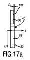
図17a乃至20は、少なくとも第1の壁部分100の実質的な部分としての機能を果たすことがあるメタルコンポーネント40の更なる有利な代替的な実施態様を例示している。図17a及び図17bは、例示的な歯ステム部分88の側面図を示しており、固定要素90が歯ステム部分88から延びている。図18乃至20は、例示的な歯ステム部分88の底面図を例示しており、それぞれの固定要素90が歯ステム部分88から突出している。図5乃至10に例示した静止ブレード22の実施態様との関係において既に説明したように、静止ブレード22のプラスチックコンポーネント38が、固定要素90、即ち、歯ステム部分88から突出する固定要素の側を全体的に覆うことがあるように、固定要素90を形成するのが、有利なことがある。静止ブレード22の頂面32(図2を参照のこと)が基本的に平面的又は平坦である、或いは、より一般的には、(存在するならば)横方向保護要素42を除き滑らかな表面を含むことが更に好ましいので、プラスチック材料が鋳造時に頂面134を覆うことがあってよもよいよう、固定要素90の頂面134にある程度の空間又はオフセットを設けるのが有利である。この関係において述べるに値するのは、頂面32の好適な平面的又は平坦な形状が、実際には、第1の壁部分100及びその頂面32が僅かに湾曲させられ或いは曲げられてよいことを必ずしも排除しないことである。対照的に、少なくとも幾つかの実施態様では、第1の壁部分100が僅かに凸状の長手方向の延伸を示すことが想定されてよい。 17 a to 20 illustrate a further advantageous alternative embodiment of the
図17は、固定要素90が頂面32からオフセットさせられた、具体的には、実質的に平行な方法においてオフセットさせられた、静止ブレード40の実施態様を例示している。結果として得られるオフセット寸法loが図17aに示されている。オフセット寸法loは、例えば、約0.03mm〜0.1mmの軟以内にあってよい。図17bは、メタルコンポーネント40の歯ステム部分88での固定要素90の更なる代替的な実施態様を例示している。図17aに例示する実施態様と同様に、図17bに示す歯ステム部分90は、メタルコンポーネント40の頂面32からオフセットさせられてよい。更に、固定要素90は、歯ステム部分40に対して傾斜させられ或いは曲げられてよい。垂直オフセット寸法が、図17b中にloによって示されている。傾斜角度が、図17b中にα(アルファ)によって示されてよい。一例として、オフセット寸法loは、約0.03mm〜0.08mmの範囲内にあってよい。傾斜角度αは、好ましくは、鋭角である。一例として、傾斜角度αは、約10°(度)〜約35°(度)の軟以内にあってよい。FIG. 17 illustrates an embodiment of the
図18は、図17bに示す実施態様に従って形成されてよい固定要素90を含む歯ステム部分88の底面図を例示している。歯ステム部分88は、固定要素90の横方向延伸又は幅waよりも大きい横方向延伸又は幅wsを含んでよい。延伸waは、プラスチックコンポーネント38のプラスチック材料が、歯ステム部分88の幅wsを越えずに固定要素90の(横方向)表面も覆ってよいように、選択されてよい。固定要素90は、固定要素90及びプラスチックコンポーネント38のしっかりした連結を可能にするよう、幾つかの凹み構成、具体的には、棘付き構成を含むのが、概ね好ましい。図6に既に示したように、固定要素90は、孔、スロット、又は、より具体的には、スロット孔92を備えてよい。故に、プラスチック材料は、それぞれの凹部92に入る。結果的に、メタルコンポーネント40及びプラスチックコンポーネント38は、しっかり連結された方法において、そして、追加的に、形態嵌め(form-fit)式に、それぞれの結合部分で接続されてよい。図19及び図20は、歯ステム部分88のための固定要素90の更なる例示的な実施態様を例示している。一例として、図19及び図20に例示する固定要素90は、図17aに示す実施態様に従って形成されてよい。図19の固定要素90は、孔のような、具体的には、円筒形の孔のような、凹み部分92を含んでよい。図20に例示する固定要素90は、横方向凹部として構成される凹み部分92を含んでよい。結果的に、固定要素90は、(90°だけ回転させられた)H形状の形態を基本的に含んでよい。FIG. 18 illustrates a bottom view of a
図17乃至20に例示する例示的な実施態様は、理解のために提供される有益な例示的な実施として主に解釈されるべきである。従って、固定要素90及びそれらのそれぞれの凹み部分92の様々な代替的な実施態様が、本開示の範囲から逸脱せずに想定されることがある。メタルコンポーネント40及びプラスチックコンポーネント38が、結合された方法において、しかしながら、形態嵌め(form fit)の方法においても、固定要素として接続されてよいよう、固定要素90は、形態嵌め要素を備えることが、概ね好ましい。 The exemplary embodiments illustrated in FIGS. 17-20 should be primarily construed as informative exemplary implementations provided for understanding. Accordingly, various alternative implementations of the securing
メタル−プラスチック複合静止ブレード22のためのメタルコンポーネント40の更なる有益な実施態様を例示する図21乃至23を更に参照する。上で例示し且つ説明したように、固定要素90が、メタルコンポーネント40の歯ステム部分88に、具体的には、歯ステム部分88の長手方向端に設けられるのが、特に好ましい。図21及び図22に示すような固定要素90は、メタルコンポーネントとプラスチックコンポーネント38との間の確実な固定的な連結、具体的には、基本的に切離し不能な結合を保証する。固定要素90が、フック又は棘付きフックとして基本的に作用して、固定要素90を介した歯ステム部分88でのプラスチック材料のしっかりした適合を保証する、(特に縦方向Xに対して垂直な平面内で見るときに)何らかのアンダーカット幾何学的構成をもたらすのが、更に好ましい。 Reference is further made to FIGS. 21-23, which illustrate additional beneficial embodiments of the
図21の側面図及び図22の底面図に見ることができるように、固定要素90は、湾曲形状、具体的には、フック状の形状を示してよい。より具体的には、固定要素90は、第1の傾斜部分128と、第2の傾斜部分130とを含んでよい。第1の傾斜部分128及び第2の傾斜部分130の両方は、移行領域で、具体的には、湾曲した或いは丸められた移行領域で、互いに接続され或いは合体させられてよい。横方向Yに対して垂直な平面において見るとき、固定要素90は、基本的に一定な(断面)区画を含んでよい。換言すると、第1の傾斜部分128及び第2の傾斜部分130は、縦方向Xに対して傾斜させられてよい。更に、第1の傾斜部分128及び第2の傾斜部分130は、互いに対して逆に傾斜させられてよい。故に、固定要素90のフック状の形状は、プラスチック材料をそこに定着させる(fixate)ことがある。例えば、それぞれの歯ステム部分88から出発して、第1の傾斜部分128は、底側に向かって傾斜させられてよく、第2の傾斜部分130は、上側に対して傾斜させられてよい。好適な結果として、固定要素90と接触するプラスチックコンポーネント38のそれぞれの部分は、損傷されなければ或いは破壊されさえしなければ、メタルコンポーネント40から切り離されない或いは解放されないことがある。換言すると、プラスチックコンポーネント38は、メタルコンポーネント40と切離し不能にリンクされてよい。 As can be seen in the side view of FIG. 21 and the bottom view of FIG. 22, the fixing
歯ステム部分88は、固定要素90の横方向延伸又は幅waよりも大きい横方向延伸又は幅wsを含んでよい。この点に関しては、図18を参照のこと。プラスチック材料が鋳造時に上側134を覆うこともあるように、固定要素90の上側134に何らかの空間又はオフセットを設けるのが、更に有利なことがある。好ましくは、プラスチック材料は、結合状態において固定要素を全体的に覆ってよい。これを達成するために、それぞれの固定要素90は、頂面32からオフセットさせられてよい。図21中のオフセット寸法loも参照のこと。The tooth stem
図21乃至23に例示する実施態様に従った固定要素90は、特定の凹部がそこに処理される必要がないという利点を有することがある(図18乃至20中の凹部又は孔92を参照のこと)。これはメタルコンポーネント40の製造を更に単純化することがある。一例として、図21乃至23の固定要素90は、材料成形プロセスを通じて、具体的には、冷間成形によって得られてよい。故に、湾曲した固定要素90を形作るために、材料除去プロセスは必要でない。これは、例えば、比較的複雑なエッチングプロセスを更に回避することがある。一例として、メタルコンポーネントの未加工の形状が、切断プロセスを通じて、具体的には、スタンピングプロセスを通じて得られてよい。次に、未加工の部品は、材料成形プロセスをそこに適用することによって、更に形作られてよい。この脈絡では、スタンピングプロセス及び曲げプロセスの組み合わせも想定されてよい。 The securing
それぞれの湾曲した固定要素90を備えるメタルコンポーネント40の部分斜視図が図23に示されている。最終製造状態において、固定要素90は、プラスチックコンポーネント38によって覆われる。図23は、メタルコンポーネント40の横方向端142を更に例示している。一般的に、メタルコンポーネント40は、2つの対向する横方向端142を含んでよい。横方向端142の中央部分に、ノッチ又は凹部144が設けられてよい。ノッチ144は、基本的に四角形又は長方形であってよい。一般的に、ノッチ144をメタルコンポーネント40の横方向端142にある横方向スロットと呼ぶことがある。上述のように、それぞれの横方向保護要素42は、メタルコンポーネント40の横方向端142に取り付けられてよい。図3乃至5も参照のこと。好ましくは、横方向保護要素42は、プラスチックコンポーネント38内に一体的に設けられる。結果的に、ノッチ144に類似の固定要素146を設けるのが有益なことがある。固定要素146を側方保護体固定よそ146と呼ぶこともある。固定要素146は、縦軸Xに対して少なくとも部分的に湾曲させられ或いは傾斜させられてよい。図23に更に見ることができるように、好ましくは、ノッチ144の両側に2つの固定要素146が設けられる。これは横方向端142での横方向保護要素42の固着(fixation)を更に強化することがある。固定要素146は対向して方向付けられる(従って、対向して傾斜させられる)ので、それらは鋳造状態において同じ横方向保護要素42によって覆われるので、2つの対応する傾斜部分を備える固定要素146を設けることは絶対的に必要ではない。また、ノッチ144にある固定要素146は、成形プロセスを通じて、具体的には、冷間成形プロセスを通じて得られてよい。未加工の固定要素を含むノッチ144は、切断プロセスを通じて、具体的には、スタンピングプロセスを通じて得られてよい。本開示の範囲から逸脱せずに図17a乃至23に示す実施態様の幾つかの特徴を組み合わせてよいのは言うまでもない。 A partial perspective view of a
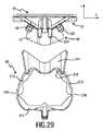
図24、25及び26を参照して、静止ブレード22の製造に関連する特徴を例示し且つ更に詳細に記載する。図24は、プラスチックコンポーネント38及びメタルコンポーネント40を含む静止ブレード22の側面図である。プラスチックコンポーネント38及びメタルコンポーネント40は、可動カッタブレード24のためのガイドスロット96を取り囲むシェルを共同で定める。図15及び図16も参照のこと。図25は、例示的な目的のために、ガイドスロット96の断面領域を例示している。静止ブレード22を製造することは、基本的に、メタルコンポーネント40を型内に挿入し、ガイドスロット96のために必要とされる空間を充填し、且つプラスチックコンポーネントを鋳造し、具体的には、プラスチックコンポーネント38を射出成形し、それにより、プラスチックコンポーネント38をメタルコンポーネント40に結合させることを含む。ガイドスロット96を基本的に定めるキャビティ(空洞)は、図25に示す断面に従って形作られる、いわゆる置換コンポーネント140で充填されてよい。置換コンポーネント140は、ダミーコンポーネント140と考えられもよい。置換コンポーネント140は、プラスチックコンポーネント38のために型内に挿入され、ガイドスロット36の空間を占めてよい。置換コンポーネント140は、再使用可能な置換コンポーネント又は損失置換コンポーネントと呼ぶこともある再使用不能な置換コンポーネントとして配置されてよい。 With reference to FIGS. 24, 25 and 26, features associated with manufacturing
静止ブレード22の破壊された底面図と、静止ブレード22のための型136の図式的な例示とを含む、図26を更に参照する。一例として、静止ブレード22を形成するための型136は、密接に接触するよう互いに対して移動させられ、それにより、静止ブレード22のための、具体的には、そのプラスチックコンポーネント38のための成形キャビティを定めるように配置される、2つの(主)型半体138−1,138−2を含んでよい。型半体138−1,138−2のそれぞれの(長手方向の)動きを示す、図26中のそれぞれの矢印も参照のこと。置換コンポーネント140が再使用可能なコンポーネントとして配置される場合、置換コンポーネント140は、少なくとも1つのスライドによって、具体的には、少なくとも1つの横方向に移動可能なスライド140−1,140−2によって具現されてよい。一例として、第1のスライド140−1及び第2のスライド140−2が、型半体138−1,138−2によって定められるキャビティ内に移動させられ、それにより、ガイドスロット96を定める空間を占めるように、配置されてよい。ガイドスロット96を形成するために単一のスライド140が用いられる、代替的な実施態様が想定されてよいのは言うまでもない。型半体138−1,138−2及びスライド140−1,140−2は、静止ブレード22の形状を定める型136のコンポーネントを形成してよい。型136が、更なるコンポーネント、例えば、更なるスライド等を含んでよいことは、言うまでもない。静止ブレードのプラスチックコンポーネント38の比較的複雑な統合的な幾何学的構成を形成するために、更なる型コンポーネントが必要とされることがある。例えば、図3及び図4に示す取付け要素48を参照のこと。ガイド要素122及び開口スロット120のような、静止ブレード22の一層更なるコンポーネントさえも、少なくとも1つの追加的なスライドによって形成されてよい。 Reference is further made to FIG. 26, which includes a broken down bottom view of the
型半体138−1,138−2及びスライド140−1,1402−2は、主として例示的な目的のために、幾分単純化された様式において図26に例示されていることが理解されるべきである。型半体138−1,138−2及びスライド140−1,1402−2の更なる詳細な輪郭及び形状を、本明細書中に提供される静止ブレード22の外側形状及び幾何学的構成の例示及び既述から導き出し得る。 It is understood that the mold halves 138-1, 138-2 and slides 140-1, 1402-2 are illustrated in FIG. 26 in a somewhat simplified manner, primarily for exemplary purposes. Should be. More detailed contours and shapes of mold halves 138-1, 138-2 and slides 140-1, 1402-2 are provided to illustrate the outer shape and geometry of
更に、更なる代替的な金型(tooling)着想及び/又は離型(demolding)アプローチが想定されてよいことが理解されるべきである。例えば、プラスチックコンポーネント38の少なくとも中央部分は、Z方向に離型されてよい。結果的に、それぞれのスライドは、静止ブレード22のための型内に存在してよい。 Furthermore, it should be understood that further alternative tooling ideas and/or demolding approaches may be envisaged. For example, at least the central portion of the
更に他の例示的な実施態様において、置換コンポーネント140は、型136と別個のコンポーネントとして配置されてよい。換言すると、置換コンポーネントは、代替的に、メタルコンポーネント40と共に型136によって定められるキャビティ内に挿入されてよいインサートコンポーネントとして配置されてよい。しかしながら、静止ブレード22を鋳造し、冷却し、且つ型136から取り外した後に、そのようなインサート置換コンポーネント140は、鋳造された静止ブレード22から取り外し可能であるのが好ましい。また、この実施態様によれば、置換コンポーネント140は、再使用可能な置換コンポーネントであってよい。 In yet another exemplary embodiment,
更に他の実施態様では、既に上述したように、置換コンポーネント140は、いわゆる損失インサートコンポーネントと呼ぶこともある再使用不能なコンポーネントとして配置されてよい。これは、置換コンポーネント140が静止ブレード22から取り外されるために、置換コンポーネント140が傷付けられ或いは破壊される必要がある、例示的な実施態様を含んでよい。 In yet another embodiment, as already mentioned above, the
図27乃至30は、ブレードセット20の、具体的には、その静止ブレード22の、更なる有益な実施態様を例示している。既に上述したように、静止ブレード22の少なくとも実質的な部分は、プラスチックコンポーネント38によって形成されてよい。更なる機能が、更なる部品を静止ブレード22に追加し或いは取り付けることを必要とせずに、静止ブレード22に統合されてよい。図27は、静止ブレード22及び可動カッタブレード24及びそれに取り付けられる伝動部材70を含む、ブレードセット20の斜視底面図である。図27」は、ブレードセット20を取り付けてよいリンケージ機構50を更に例示している。図2も参照のこと。図27において、ブレードセット20は、解放された或いは切り離された状態において示されている。 27 to 30 illustrate further beneficial embodiments of the blade set 20, and in particular of its
図27に示すように、リンケージ機構50は、4バーリンケージ機構として構成されてよい。リンケージ機構50は、少なくとも1つのリンケージ要素208、具体的には、横方向Yにおいて互いから横方向に離間する第1のリンケージ要素208−1及び第2のリンケージ要素208−2を含んでよい。少なくとも1つのリンケージ要素208は、ベース210を含んでよく、ベースをリンケージ機構50及び毛切断器具10のハウジング12を接続する接触要素と呼ぶこともある。図1も参照のこと。リンケージ要素208は、ベース210の反対に配置される頂部分又はトップ214を更に含んでよい。リンケージ要素208は、ベース210及びトップ214を接続する連結要素を更に含んでよい。例えば、リンケージ要素208は、2つの連結アーム212を含んでよく、各々の連結アーム212は、ベース210とトップ214との間に配置されてよい。連結アーム212は、縦方向Yにおいて互いに長手方向に離間してよい。ベース210及びトップ214は、垂直又は高さ方向Zにおいて互いに離間してよい。1つの例示的な実施態様において、リンケージ要素208のそれぞれの部材は、膜ヒンジ216を介して互いに連結されてよい。膜ヒンジ216(図28も参照のこと)は、リンケージ要素208の隣接部材に、互いに対して旋回する能力をもたらしてよい。結果的に、ブレードセット20は、リンケージ機構50に取り付けられている間に、横方向を定める軸Yと実質的に平行な垂直軸について、毛切断器具のハウジング12に対して旋回し或いはスイベルしてよい。 As shown in FIG. 27, the
静止ブレード22は、第2の壁部分102がリンケージ要素のトップ214と接触することあるように、具体的には、その第2の壁部分102で、取付け要素48を備えてよい。結果的に、ブレードセット20及びトップ214は、少なくとも1つのリンケージ要素208のベース210に対して共同でスイベルし或いは旋回してよい。リンケージ要素208のトップ214に、リミットストップ構成218が設けられてよい。リミットストップ構成218は、毛切断器具10のハウジング12と関連付けられる対応するリミットストップ要素(図27には示されていない)に当接するように構成されてよい。 The
図28は、リンケージ機構50の斜視頂面図を例示している。図29は、図27に示す構成の側面図を例示しており、ブレードセット20は、リンケージ機構50から取り外されている。図30は、ブレードセット20の断面図を例示しており、取付け要素48を通じる断面が例示されている。図27及び図30に見ることができるように、取付け要素48は、リンケージ要素208のトップ214にある少なくとも1つのそれぞれのガイド凹部220及び少なくとも1つのそれぞれ取付け凹部222と協働するように構成されてよい、少なくとも1つのガイド突起224及び少なくとも1つの取付け突起226を含んでよい(図28を参照のこと)。図29に見ることができるように、ブレードセット20は、取付けのためにリンケージ機構50に対して基本的に垂直に送られてよい。結果的に、少なくとも1つのガイド突起224及び少なくとも1つの対応するガイド凹部220は、垂直方向(Z方向)に概ね延在してよい。少なくとも1つのガイド凹部220及び少なくとも1つのガイド突起224は、ブレードセット20が取付けのための所望の向きを取るのを保証することがある。代替的な送り方向を含む代替的な取付けアプローチが想定されてよいのは言うまでもない。プラスチックコンポーネント38は、比較的大きな設計の自由度で形成されてよいので、ブレードセット20は、任意のそれぞれの取付け着想に適切に適合させられてよい。 FIG. 28 illustrates a perspective top view of the
対照的に、少なくとも1つの取付け凹部222及び少なくとも1つの対応する取付け突起226は、干渉嵌め又はスナップ留め取付けのために構成されてよい。幾つかの実施態様において、少なくとも1つの取付け凹部222及び少なくとも1つの取付け突起226は、スナップ留め取付け要素として構成されてよい。図30に最良に見ることができるように、少なくとも1つの取付け突起226は、少なくとも部分的に又は局地的に縦方向Xに延在してよい。結果的に、少なくとも1つの取付け突起226は、付勢式に又はスナップ留め式に、それぞれの取付け凹部222と係合してよい。換言すると、少なくとも1つの取付け突起226は、係合状態において或いは取付け状態において取り付けられるときに、少なくとも僅かに予荷重を加えられてよい。一般的に、取付け突起226は、少なくとも部分的に又は局所的に横方向Y及び垂直方向Zによって定められる平面に対して傾斜させられてよい(図27も参照のこと)。結果的に、取付け凹部222との係合後、取付け突起226は、リンケージ機構50からのブレードセット20の望ましくない離脱を防止することがある少なくとも長手成分を含む、保持力を加えることがある。 In contrast, at least one mounting
図27乃至30に例示的に示すように、リンケージ要素208−1,208−2の各々は、取付け要素48のそれぞれのセットと関連付けられてよい。取付け要素48の各セットは、リンケージ要素208−1,208−2の各々でそれぞれの対のガイド凹部220及び取付け凹部222と協働するように配置されてよい、一対のガイド突起224及び一対の取付け突起226を含んでよい。 Each of the linkage elements 208-1, 208-2 may be associated with a respective set of
図31を参照して、本開示の幾つかの特徴に従ったブレードセット20の静止ブレード22の例示的な製造方法を例示し且つ更に詳説する。第1のステップS10で、静止ブレードのメタルコンポーネントを形成するための未加工材料又は半仕上げ材料が提供されてよい。これはシートメタル材料を提供することを含んでよい。シートメタル材料を提供することは、コイルからシートメタル材料を供給することを含んでよい。それぞれの中間メタ材料は、複数の部分を含んでよく、それらの各々は、静止ブレードのために仕上げられるべきメタルコンポーネントを定める。例えば、これらの明確な先駆部分の各々は、スタンピング又は他の適切な切断方法によって処理されてよい。 31, an exemplary method of manufacturing
処理されるべきメタルコンポーネントの中間前縁、具体的には、中間歯付き前縁を形成することを含んでよい、更なるステップS12が続いてよい。一例として、ステップS12は、前縁に歯ステム部分を形成することを含んでよい。歯ステム部分を形成することは、それぞれの歯ステム部分の間にスロットを定めるよう、それぞれの歯ステム部分の間の材料を除去することを含んでよい。これは適切な材料除去プロセス、例えば、スタンピング、レーザ切断、ワイヤ切断、及びエッチングを含んでよい。更なる材料除去プロセスが想定されてよい。メタルコンポーネントのそれぞれの前縁で歯ステム部分を形成することは、歯ステム部分に、具体的には、その横方向フランクに、相当に鋭利な切断エッジを形成することを更に含んでよい。歯ステム部分をエッチングすることは、歯ステム部分の一般的な形態を処理すること及びそれらのフランクに比較的鋭利な切断エッジを更に創ることを含んでよい。 A further step S12 may be followed which may include forming an intermediate leading edge of the metal component to be processed, in particular an intermediate toothed leading edge. As an example, step S12 may include forming a tooth stem portion on the leading edge. Forming the tooth stem portions may include removing material between the respective tooth stem portions to define a slot between the respective tooth stem portions. This may include any suitable material removal process, such as stamping, laser cutting, wire cutting, and etching. Further material removal processes may be envisioned. Forming a tooth stem portion at each leading edge of the metal component may further include forming a substantially sharp cutting edge on the tooth stem portion, and in particular on its lateral flanks. Etching the tooth stem portions may include treating the general morphology of the tooth stem portions and further creating relatively sharp cutting edges in their flanks.
固定部分を形成する又は処理することを含んでよい、更なるステップS14が続いてよい。好ましくは、固定部分は、前縁にある歯ステム部分の長手方向端から延びる。固定部分は、好ましくは、鋳造可能な材料によって係合され且つ充填されてよい、凹部又は類似の要素を含んでよい。歯ステム部分にある固定部分は、それらが鋳造される又は鋳造可能なコンポーネントによって覆われて、固定部分と歯ステム部分との間の移行部に有意な段のない概ね滑らかな表面をもたらすよう、その皮膚に面する横方向の側で更に機械加工されるのが、更に好ましい(図6及び図17乃至20も参照のこと)。ステップS14及びS12を組み合わせてよいのは言うまでもない。例えば、ステップS12及びS14は、統合スタンピング(integrated stamping)(又は代替的にエッチング)ステップによって実施されてよい。 A further step S14 may be followed, which may include forming or treating the fixed part. Preferably, the fixed portion extends from the longitudinal end of the tooth stem portion at the leading edge. The fixed portion may preferably include a recess or similar element that may be engaged and filled with a castable material. The anchoring portions on the tooth stem portion are covered by cast or castable components to provide a significant stepless generally smooth surface at the transition between the anchoring portion and the tooth stem portion, More preferably, it is further machined on its lateral side facing the skin (see also FIGS. 6 and 17-20). It goes without saying that steps S14 and S12 may be combined. For example, steps S12 and S14 may be performed by an integrated stamping (or alternatively etching) step.
任意的なステップと考えられてよい更なるステップS16で、固定要素又は固定部分は、歯ステム部分に対して曲げられてよい。固定部分を曲げることは、鋳造される材料及びメタルコンポーネントの固着を更に強化することがある。何故ならば、より多くの空間がプラスチック材料のために提供されることがあるからである。ステップS16を必要としない製造方法の少なくとも幾つかの実施態様があってよい。 In a further step S16, which may be considered as an optional step, the fixing element or the fixing part may be bent with respect to the tooth stem part. Bending the fixed portion may further strengthen the bond of the cast material and metal components. This is because more space may be provided for the plastic material. There may be at least some implementations of the manufacturing method that do not require step S16.
供給されるメタル材料での、具体的には、供給されるシートメタル材料での、例えば、供給されるシートメタルコイルでの、それぞれの列又は配列(アレイ)から、メタルコンポーネントのための複数の先駆体を分離することを含んでよい、更なる任意的なステップS18が続いてよい。ステップS18は、それぞれの支持構造からそれぞれの先駆体を切断する又はスタンピングすることを含んでよい。これに関して述べるに値するのは、分離するステップS18は、代替的に、図31に例示する製造プロセスの他の段階で起こってもよいことである。製造プロセスの早い段階に又は比較的遅い段階にメタルコンポーネント先駆体を分離することは選択の問題と考えられてよい。結果的に、幾つかの実施態様において、静止ブレードのメタルコンポーネントは、例えば、ステップS16又はステップS18で、少なくとも実質的に仕上げられてよい。 From the respective rows or arrays of metal material supplied, in particular of the supplied sheet metal material, for example in the supplied sheet metal coil, a plurality of metal components for the metal component is provided. A further optional step S18 may be followed, which may include separating the precursors. Step S18 may include cutting or stamping each precursor from each support structure. It is worth mentioning in this regard that the separating step S18 may alternatively occur at other stages of the manufacturing process illustrated in FIG. Separation of metal component precursors early in the manufacturing process or relatively late may be considered a matter of choice. Consequently, in some implementations, the metal components of the stationary blade may be at least substantially finished, eg, at step S16 or step S18.
メタルコンポーネントを成形型のキャビティ内に配置することを含んでよい、更なるステップS20が続いてよい。メタルコンポーネントを配置することは、メタルコンポーネントを型のキャビティ内に明確な向きにおいて配置することを含んでよい。既に上述したように、メタルコンポーネントは、その分離された状態において型キャビティ内に配置されてよい。しかしながら、少なくとも幾つかの実施態様では、それぞれの複数のキャビティを含む型内に複数のメタルコンポーネントを配置することが想定されてよい。複数のメタルコンポーネントのそれぞれのメタルコンポーネントは、互いに分離されてよい。しかしながら、代替的に、メタルコンポーネントは共通の支持構造に取り付けられてよい。 A further step S20 may follow, which may include placing the metal component in the mold cavity. Placing the metal component may include placing the metal component in a well-defined orientation within the mold cavity. As already mentioned above, the metal component may be placed in the mold cavity in its separated state. However, in at least some implementations, it may be envisioned to place multiple metal components in a mold that includes multiple cavities of each. Each metal component of the plurality of metal components may be separated from each other. However, alternatively, the metal components may be attached to a common support structure.
型のキャビティ内にメタルコンポーネントを配置した後、置換コンポーネントを型内に配置することが続いてよい。置換コンポーネントは、型キャビティ内の空間を覆い或いは充填して、形成されるべき静止ブレード内のガイドスロットを定めてよい。置換コンポーネントを型内に配置することは、再使用可能な又は再使用不能な置換コンポーネントを型内に配置することを含んでよい。一例として、ステップS22は、少なくとも1つのスライドを型のキャビティ内に挿入することを含んでよい。少なくとも1つのスライドは、成形型のコンポーネントと考えられてよい。例えば、成形型は、置換コンポーネントを形成する2つの対向するスライドを備えてよい。 After placing the metal component in the cavity of the mold, placing the replacement component in the mold may follow. The replacement component may cover or fill the space within the mold cavity to define a guide slot within the stationary blade to be formed. Placing the replacement component in the mold may include placing the reusable or non-reusable replacement component in the mold. As an example, step S22 may include inserting at least one slide into the mold cavity. At least one slide may be considered a component of the mold. For example, the mold may comprise two opposing slides forming a replacement component.
鋳造ステップと考えられてよい更なるステップS24が続いてよい。鋳造ステップS24で、鋳造される又は鋳造可能な材料が型のキャビティ内に射出されてよい。ステップS24を射出成形ステップと呼ぶことがある。ステップS24は、溶融プラスチック材料を型キャビティ内に射出することを含んでよい。結果的に、型内のキャビティは、基本的に流動プラスチック材料で充填されてよい。プラスチック材料は、形成されるべき静止ブレードのプラスチックコンポーネントを定めてよい。プラスチックコンポーネントは、メタルコンポーネントに、具体的には、その固定要素又は固定部分に結合されてよい。メタルコンポーネント及びプラスチックコンポーネントを接続することは、固定部分にある凹み部分を鋳造されるプラスチック材料と係合させることを更に含んでよい。一般的に、ステップS24は、一体的に形成されるメタル−プラスチック複合静止ブレードを創ってよい。特に、ステップS24をインサート成形ステップと呼ぶことがある。従って、メタルコンポーネントは、インサートコンポーネントと考えられてよい。幾つかの実施態様において、ステップS24は、アウトサート成形ステップと考えられてよい。更に幾つかの更なる実施態様において、ステップS24は、オーバーモールドステップと考えられてよい。 A further step S24, which may be considered as a casting step, may follow. In the casting step S24, a cast or castable material may be injected into the mold cavity. Step S24 may be called an injection molding step. Step S24 may include injecting molten plastic material into the mold cavity. As a result, the cavities in the mold may essentially be filled with a flowing plastic material. The plastic material may define the plastic component of the stationary blade to be formed. The plastic component may be bonded to the metal component, in particular to its fastening element or fastening part. Connecting the metal component and the plastic component may further include engaging a recessed portion in the fixed portion with the cast plastic material. Generally, step S24 may create a integrally formed metal-plastic composite stationary blade. In particular, step S24 may be called an insert molding step. Therefore, the metal component may be considered an insert component. In some implementations, step S24 may be considered an outsert molding step. In some further embodiments, step S24 may be considered an overmolding step.
存在するならば、少なくとも1つのスライドを、型のキャビティから取り外すことを含んでよい、更なるステップS26が続いてよい。結果的に、静止ブレードに形成されるガイドスロットが空けられてよい。ガイドスロットは、静止ブレードでの取り付けられるべき可動カッタブレードのための明確な噛合い(mating)をもたらすことがある。 If present, a further step S26 may be followed, which may include removing at least one slide from the mold cavity. As a result, guide slots formed in the stationary blade may be emptied. The guide slot may provide a positive mating for the movable cutter blade to be attached with the stationary blade.
任意的なステップと考えられてよい更なるステップS28が続いてよい。ステップS28は、複数のそれぞれの型キャビティを含む型内に形成される複数の静止ブレードを含む配列(アレイ)又は列から単一の静止ブレードを分離することを含んでよい。 A further step S28, which may be considered an optional step, may follow. Step S28 may include separating a single stationary blade from an array or row that includes a plurality of stationary blades formed in a mold that includes a plurality of respective mold cavities.
図31に従って静止ブレードを製造する方法は、中間壁部分を提供することに向けられるステップS30を更に含んでよい。ステップS30は、シートメタル中間壁部分を提供することを含んでよい。中間壁部分は、静止ブレードの第1の壁部分と第2の壁部分との間の所望の中央オフセットlcoに適合させられてよい。中間壁部分は、後の製造段階で(半仕上げ)静止ブレードに取り付けられてよい別個の部品として形成されてよい。故に、図31に従う方法は、2つの別個の部品、即ち、(半仕上げ)静止ブレード及び後の段階でそこに取り付けられるべき中間壁部分をもたらしてよい。ステップS30は、少なくとも幾つかの実施態様において、ガイド部分と保持部分とを含む中間壁部分を形成することを含んでよい。故に、ステップS30は、ガイド部分及び保持部分を別個に形成して接合することを含んでよい。代替的に、ステップS30は、中間壁部分のガイド部分及び保持部分を一体的に形成することを含んでよい。 The method of manufacturing a stationary blade according to FIG. 31 may further include a step S30 directed to providing the intermediate wall portion. Step S30 may include providing a sheet metal intermediate wall portion. The intermediate wall portion may be adapted to a desired central offset lco between the first wall portion and the second wall portion of the stationary blade. The intermediate wall portion may be formed as a separate piece that may be attached to the (semi-finished) stationary blade at a later manufacturing stage. Therefore, the method according to FIG. 31 may result in two separate parts, a (semi-finished) stationary blade and an intermediate wall part to be attached thereto at a later stage. Step S30 may, in at least some embodiments, include forming an intermediate wall portion that includes a guide portion and a retaining portion. Thus, step S30 may include separately forming and joining the guide portion and the retaining portion. Alternatively, step S30 may include integrally forming the guide portion and the retaining portion of the intermediate wall portion.
図32は、本開示の少なくとも幾つかの特徴に従って形成され且つ構成される静止ブレードと協働するように構成されてよい可動カッタブレードのための例示的な製造方法を例示している。ステップS50で、可動カッタブレードのための先駆体又は半仕上げ可動カッタブレードが提供されてよい。これは複数の処理されるべき可動カッタブレードの所定の列又は配列(アレイ)を含んでよいシートメタル材料を提供することを含んでよい。可動カッタブレードに凹部又は開口を形成することを含んでよい更なるステップS52が続いてよい。開口をガイド開口と呼ぶことがある。ガイド開口は、静止ブレードの中間壁部分に、具体的には、そのガイド部分に適合させられてよい。ガイド開口は、可動カッタブレードの中央部分にある基本的に長方形の横方向に延びるスロットとして構成されてよい。一般的に、ステップS52は、切断、スタンピング、エッチング等のような、適切な材料除去プロセスを含んでよい。 32 illustrates an exemplary manufacturing method for a movable cutter blade that may be configured to cooperate with a stationary blade formed and configured in accordance with at least some features of the present disclosure. In step S50, a precursor or semi-finished movable cutter blade for the movable cutter blade may be provided. This may include providing a sheet metal material that may include a plurality of predetermined rows or arrays of movable cutter blades to be processed. Further steps S52 may be followed which may include forming recesses or openings in the movable cutter blade. The opening may be referred to as a guide opening. The guide opening may be fitted to the intermediate wall part of the stationary blade, in particular to that guide part. The guide opening may be configured as an essentially rectangular laterally extending slot in the central portion of the movable cutter blade. In general, step S52 may include a suitable material removal process such as cutting, stamping, etching and the like.
可動カッタブレードの歯付き前縁を形成すること又は処理することを含んでよい、更なるステップS54が続いてよい。ステップS54は、歯付き前縁のそれぞれの歯に比較的鋭利な切断エッジを処理することを更に含んでよい。ステップS54は、適切な材料除去プロセスを含んでよい。一例として、ステップS54は、歯付き前縁に概ね歯付き形状を形成すること及び歯に比較的鋭利な切断エッジを形成することを含む、統合エッチングステップを含んでよい。好ましくは、ステップS52及びS54は、(化学的切削加工とも呼ばれる)エッチングを利用する材料除去プロセスを活用する。ステップS52及びS54の順序が変えられてよいのは言うまでもない。幾つかの実施態様において、ステップS52及びS54の両方は、共同で行われてよい。複数の可動カッタブレードの列又は配列(アレイ)を含む支持構造からそれぞれの可動カッタブレードを分離することを含んでよい、更なるステップS56が続いてよい。 A further step S54, which may include forming or treating the toothed leading edge of the movable cutter blade, may be followed. Step S54 may further include processing a relatively sharp cutting edge on each tooth of the toothed leading edge. Step S54 may include a suitable material removal process. As an example, step S54 may include an integrated etching step that includes forming a generally toothed shape on the toothed leading edge and forming a relatively sharp cutting edge on the tooth. Preferably, steps S52 and S54 utilize a material removal process that utilizes etching (also referred to as chemical cutting). It goes without saying that the order of steps S52 and S54 may be changed. In some implementations, both steps S52 and S54 may be performed jointly. A further step S56 may be followed, which may include separating each movable cutter blade from a support structure that includes a row or array of movable cutter blades.
図33は、本開示の少なくとも幾つかの特徴に従って形成される静止ブレード及び可動ブレードを含むブレードセットのための例示的な製造方法を例示している。方法は、静止ブレードを提供することを含むステップS100を含んでよい。静止ブレードは、図31に例示する例示的な製造方法に従って形成されてよい。上述のように、ステップS100は、静止ブレードに割り当てられる(別個の)中間壁部分を提供することを更に含んでよく、静止ブレードは、後のステップで中間壁部分に取り付けられる。更なるステップS102が、可動カッタブレードを提供することを含んでよい。ステップS100及びS102は、平行に行われてよい。ステップS102は、図32に例示する方法に従って可動カッタブレードを製造することを含んでよい。 FIG. 33 illustrates an exemplary manufacturing method for a blade set including stationary blades and movable blades formed in accordance with at least some features of the present disclosure. The method may include step S100 including providing a stationary blade. The stationary blade may be formed according to the exemplary manufacturing method illustrated in FIG. As mentioned above, step S100 may further include providing a (separate) intermediate wall portion that is assigned to the stationary blade, the stationary blade being attached to the intermediate wall portion in a later step. A further step S102 may include providing a movable cutter blade. Steps S100 and S102 may be performed in parallel. Step S102 may include manufacturing a movable cutter blade according to the method illustrated in FIG.
更なるステップS104において、中間壁部分及び可動カッタブレードが噛み合わせられてよく、それは(半仕上げ)静止ブレードのガイドスロット内へのコンポーネントの挿入を単純化する。これは、中間壁部分、具体的には、そのガイド部分を、可動カッタブレードのガイド開口内に配置することを含んでよい。可動カッタブレード及び中間壁部分が静止ブレードにあるガイドスロット内に一緒に挿入される、接合又は噛み合わせステップS106はが続いてよい。可動カッタブレード及び中間壁部分を静止ブレードのガイドスロット内に挿入することは、静止ブレードの横方向開口を通じて可動カッタブレード及び中間壁部分を横方向に挿入することを含んでよい。 In a further step S104, the intermediate wall part and the movable cutter blade may be interlocked, which simplifies the insertion of the component into the guide slot of the (semi-finished) stationary blade. This may include placing the intermediate wall portion, specifically its guide portion, within the guide opening of the movable cutter blade. A joining or mating step S106 may be followed, in which the movable cutter blade and the intermediate wall portion are inserted together in the guide slots in the stationary blade. Inserting the movable cutter blade and the intermediate wall portion into the guide slot of the stationary blade may include laterally inserting the movable cutter blade and the intermediate wall portion through a lateral opening in the stationary blade.
更なるステップS108において、中間壁部分は、静止ブレードに、具体的には、その第1の壁部分に取り付けられてよい。好ましくは、中間壁部分は、第1の壁部分に結合されてよく、具体的には、レーザ溶接及び/又はスポット溶接されてよい。中間壁部分を取り付けることは、可動カッタブレードを静止ブレードに固定すること、より好ましくは、可動カッタブレードの長手方向位置及び垂直位置(又は高さ位置)を設定することを含んでよい。 In a further step S108, the intermediate wall part may be attached to the stationary blade, in particular to its first wall part. Preferably, the intermediate wall portion may be joined to the first wall portion, in particular laser welded and/or spot welded. Attaching the intermediate wall portion may include securing the movable cutter blade to the stationary blade, and more preferably setting the longitudinal and vertical position (or height position) of the movable cutter blade.
伝動部材70をブレードセットの半仕上げアセンブリに送ることを更に含んでよい、更なるステップS110が続いてよい。ステップS110は、可動カッタブレードの挿入方向と異なる給送方向において伝動部材70を送ることを特に含んでよい。伝動部材70を可動カッタブレード24に取り付けることを含む、更なるステップS112が続いてよい。ステップS112は、伝動部材を可動カッタブレードに結合することを更に含んでよい。結合することは、溶接すること、具体的には、レーザ溶接することを含んでよい。可動カッタブレード及び伝動部材の両方が静止ブレードに位置付けられる間に可動カッタブレード及び伝動部材を取り付けることは、その上、静止ブレードで可動カッタブレードを係止する。これは有益であることもある。何故ならば、このようにして、可動カッタブレードのために別個の締結又は係止コンポーネントが必要とされないからである。 A further step S110, which may further include sending the
本発明を図面及び前述の記述中に詳細に例示し且つ記載したが、そのような例示及び既述は、例示的又は例証的であると考えられるべきであり、限定的であると考えられるべきではない。本発明は、開示する実施態様に限定されない。請求する発明を実施する当業者は、図面、本開示、及び付属の請求項の研究から、開示の実施態様に対する他の変形を理解し且つ行い得る。 While the invention has been illustrated and described in detail in the drawings and foregoing description, such illustrations and descriptions are to be considered illustrative or exemplary and are to be considered restrictive. is not. The invention is not limited to the disclosed embodiments. Those skilled in the art practicing the claimed invention will understand and be able to make other variations to the disclosed embodiments from a study of the drawings, the present disclosure, and the appended claims.
請求項において、「含む」という用語は、他の要素又はステップを排除せず、単数形の表現は、複数を排除しない。単一の要素又は他のユニットが、請求項中に引用される幾つかの品目の機能を充足することがある。特定の手段が相互に異なる従属項において引用されているという単なる事実は、これらの手段の組み合わせを有利に用い得ないことを示さない。 In the claims, the term "comprising" does not exclude other elements or steps, and singular expressions do not exclude a plurality. A single element or other unit may fulfill the functions of several items recited in the claims. The mere fact that certain measures are recited in mutually different dependent claims does not indicate that a combination of these measures cannot be used to advantage.
請求項中の参照記号は、範囲を限定するものと考えられてならない。 Reference signs in the claims shall not be construed as limiting the scope.
Claims (15)
Translated fromJapanese前記ブレードセットは、毛を切断する移動方向において毛を通じて移動させられるように構成され、
当該静止ブレードは、
− 動作時に皮膚に面する壁として働くように構成される第1の壁部分と、
− 該第1の壁部分及び第2の壁部分が、それらの間に、可動カッタブレードを受け入れるように構成されるガイドスロットを定めるよう、前記第1の壁部分から少なくとも部分的にオフセットさせられる前記第2の壁部分と、
− 前記第1の壁部分と前記第2の壁部分との間で前記ガイドスロット内に配置される中間壁部分と、
− 前記第1の壁部分及び前記第2の壁部分によって共同で形成される少なくとも1つの歯付き前縁とを含み、
該少なくとも1つの歯付き前縁は、複数の歯を含み、
前記第1の壁部分及び前記第2の壁部分は、前記少なくとも1つの前縁の前方端で接続され、それにより、前記歯の先端を形成し、
当該静止ブレードは、一体的に形成されるメタル−プラスチック複合静止ブレードであり、
前記第1の壁部分は、メタル材料で作られ、
前記第2の壁部分は、プラスチック材料で作られ、
前記中間壁部分は、前記第1の壁部分と前記第2の壁部分との間の中央オフセットを定め、
前記中間壁部分は、取り付けられるべき可動カッタブレードのそれぞれの開口に適合させられる、
静止ブレード。A stationary blade for a blade set of a hair cutting device, comprising:
The blade set is configured to be moved through the bristles in a moving direction for cutting the bristles,
The stationary blade is
A first wall part configured to act as a wall facing the skin during operation;
-The first wall portion and the second wall portion are at least partially offset from the first wall portion so as to define between them a guide slot configured to receive a movable cutter blade. The second wall portion;
An intermediate wall portion arranged in the guide slot between the first wall portion and the second wall portion,
-Including at least one toothed leading edge jointly formed by said first wall portion and said second wall portion,
The at least one toothed leading edge includes a plurality of teeth,
The first wall portion and the second wall portion are connected at a front end of the at least one leading edge, thereby forming a tip of the tooth,
The stationary blade is a integrally formed metal-plastic composite stationary blade,
The first wall portion is made of a metal material,
The second wall portion is made of a plastic material,
The intermediate wall portion defines a central offset between the first wall portion and the second wall portion,
The intermediate wall portion is adapted to each opening of the movable cutter blade to be mounted,
Stationary blade.
当該ブレードセットは、毛を切断する移動方向において毛を通じて移動させられるように構成され、
当該ブレードセットは、
− 請求項1乃至5のうちのいずれか1項に記載の静止ブレードと、
− 少なくとも1つの歯付き前縁を含む可動カッタブレードとを含み、
該可動カッタブレードは、該可動カッタブレードと前記静止ブレードとの間の相対的な運動後に、前記可動カッタブレードの前記少なくとも1つの歯付き前縁が前記静止ブレードの対応する歯と協働して、切断作用において、それらの間に捕捉される毛の切断を可能にするよう、前記静止ブレードによって定められる前記ガイドスロット内に移動可能に配置され、
前記可動カッタブレードは、ガイド開口、具体的には、横方向に延びるスロットを含み、前記静止ブレードの前記中間壁部分は、前記ガイド開口内に配置される、
ブレードセット。A blade set for a hair cutting device,
The blade set is configured to be moved through the hair in a moving direction that cuts the hair,
The blade set is
-A stationary blade according to any one of claims 1 to 5,
A movable cutter blade including at least one toothed leading edge,
The movable cutter blade is configured such that, after relative movement between the movable cutter blade and the stationary blade, the at least one toothed leading edge of the movable cutter blade cooperates with a corresponding tooth of the stationary blade. Movably disposed within the guide slot defined by the stationary blade to allow cutting of the hair captured therebetween during cutting action,
The movable cutter blade includes a guide opening, specifically a laterally extending slot, the intermediate wall portion of the stationary blade disposed within the guide opening.
Blade set.
当該方法は、
− 第1の壁部分の中央部分を少なくとも実質的に形成するメタルコンポーネント、具体的には、シートメタルコンポーネントを提供するステップと、
− 中間壁部分、具体的には、シートメタル中間壁部分を提供するステップと、
− プラスチックコンポーネントの形状を定める型、具体的には、射出成形型を提供するステップと、
− 前記メタルコンポーネントを前記型内に配置するステップと、
− 鋳造時に前記静止ブレードの形成されるべきガイドスロットを空いた状態に保つように構成される置換コンポーネントを前記型内に提供するステップと、
− 前記プラスチックコンポーネントを形成する、具体的には、射出成形するステップとを含み、
前記プラスチックコンポーネント及び前記メタルコンポーネントは、前記静止ブレードの第1の壁部分及び第2の壁部分を定め、前記第1の壁部分は、動作時に皮膚に面する壁として働くように構成され、前記第2の壁部分は、前記第1の壁部分及び前記第2の壁部分がそれらの間に可動カッタブレードのためのガイドスロットを定めるよう、前記第1の壁部分から少なくとも部分的にオフセットさせられ、
前記第1の壁部分及び前記第2の壁部分は、複数の歯を含む少なくとも1つの歯付き前縁を共同で形成し、
前記第1の壁部分及び前記第2の壁部分は、前記少なくとも1つの前縁の前方端で接続され、それにより、前記歯の先端を形成し、
前記中間壁部分は、取り付けられるべき可動カッタブレードのそれぞれの開口に適合させられ、
当該方法は、
前記メタル−プラスチック複合静止ブレードから前記置換コンポーネントを除去するステップと、
前記中間壁部分が前記第1の壁部分と前記第2の壁部分との間に中央オフセットを定めるよう、前記第1の壁部分と前記第2の壁部分との間に前記中間壁部分を配置するステップとを含む、
方法。A method of manufacturing a metal-plastic composite stationary blade of a blade set for a hair cutting device, comprising:
The method is
Providing a metal component, at least a sheet metal component, which at least substantially forms the central part of the first wall part;
-Providing an intermediate wall portion, in particular a sheet metal intermediate wall portion,
Providing a mold defining the shape of the plastic component, in particular an injection mold,
Placing the metal component in the mold;
Providing in the mold a replacement component configured to keep the guide slots to be formed of the stationary blade open during casting;
-Forming said plastic component, in particular injection molding,
The plastic component and the metal component define a first wall portion and a second wall portion of the stationary blade, the first wall portion being configured to act as a skin-facing wall during operation; A second wall portion is at least partially offset from the first wall portion such that the first wall portion and the second wall portion define a guide slot for the movable cutter blade therebetween. The
The first wall portion and the second wall portion jointly form at least one toothed leading edge including a plurality of teeth;
The first wall portion and the second wall portion are connected at a front end of the at least one leading edge, thereby forming a tip of the tooth,
The intermediate wall portion is adapted to each opening of the movable cutter blade to be mounted,
The method is
Removing the replacement component from the metal-plastic composite stationary blade;
Arranging the intermediate wall portion between the first wall portion and the second wall portion such that the intermediate wall portion defines a central offset between the first wall portion and the second wall portion. Including the step of placing,
Method.
− 前記可動カッタブレードのための前記ガイドスロットを定める少なくとも1つの横方向スライドを前記型内に提供するステップ、及び
− 前記型内に別個の交換ダミーコンポーネント、具体的には、再使用可能なダミーコンポーネントを配置するステップであって、前記ダミーコンポーネントは、前記型の外側から、前記メタル−プラスチック複合静止ブレードから取り外されるステップ
のうちの少なくとも1つを含む、
請求項12に記載の方法。Providing the replacement component in the mold comprises:
Providing at least one lateral slide in the mold defining the guide slot for the movable cutter blade, and a separate replacement dummy component in the mold, in particular a reusable dummy. Disposing a component, the dummy component comprising at least one of the steps of: removing the dummy component from the outside of the mold from the metal-plastic composite stationary blade.
The method according to claim 12.
該メタルコンポーネントを機械加工するステップは、前記メタルコンポーネントで歯ステム部分を形成するステップ及び固定要素を形成するステップのうちの少なくとも1つを含み、
前記メタルコンポーネントを機械加工するステップは、
− 切断、具体的には、レーザ切断、
− エッチング、具体的には、電気化学エッチング、
− スタンピング、
− 圧印加工、
− 浸食、具体的には、ワイヤ浸食、及び
− それらの組み合わせ
で構成される群から選択される少なくとも1つのプロセスを更に含む、
請求項12又は13に記載の方法。-Further comprising machining the metal component,
Machining the metal component includes at least one of forming a tooth stem portion with the metal component and forming a fixation element,
Machining the metal component comprises:
-Cutting, specifically laser cutting,
-Etching, specifically electrochemical etching,
-Stamping,
− Coining,
-Erosion, specifically wire erosion, and-further comprising at least one process selected from the group consisting of
The method according to claim 12 or 13.
− 請求項12乃至14のうちのいずれか1項に記載の方法に従って中間壁部分を含む静止ブレードを製造するステップと、
− 前記静止ブレードの少なくとも1つのそれぞれの歯付き前縁と協働するように構成される少なくとも1つの歯付き前縁を含む可動カッタブレードを提供するステップであって、該可動カッタブレードは、ガイド開口、具体的には、横方向に延びるスロットを更に含む、ステップと、
− 前記中間壁部分を前記可動カッタブレードの前記ガイド開口内に位置付けるステップと、
− 前記可動カッタブレード及び前記中間壁部分を前記静止ブレードの前記ガイドスロット内に一緒に挿入するステップ、具体的には、前記可動カッタブレード及び前記中間壁部分を前記静止ブレードの横方向開口を通じて一緒に送るステップと、
− 前記中間壁部分を前記第1の壁部分に取り付けるステップ、具体的には、前記中間壁部分を前記第1の壁部分に結合するステップとを含む、
方法。A method of manufacturing a blade set for a hair cutting device, comprising:
Manufacturing a stationary blade including an intermediate wall portion according to the method of any one of claims 12 to 14;
Providing a movable cutter blade including at least one toothed leading edge configured to cooperate with at least one respective toothed leading edge of the stationary blade, the movable cutter blade comprising a guide; A step further comprising an opening, specifically a laterally extending slot, and
Positioning the intermediate wall portion within the guide opening of the movable cutter blade;
-Inserting the movable cutter blade and the intermediate wall portion together into the guide slot of the stationary blade, in particular the movable cutter blade and the intermediate wall portion together through a lateral opening of the stationary blade. To send to,
Attaching the intermediate wall portion to the first wall portion, specifically coupling the intermediate wall portion to the first wall portion;
Method.
Applications Claiming Priority (3)
| Application Number | Priority Date | Filing Date | Title |
|---|---|---|---|
| EP14185272.3 | 2014-09-18 | ||
| EP14185272 | 2014-09-18 | ||
| PCT/EP2015/071516WO2016042158A1 (en) | 2014-09-18 | 2015-09-18 | Blade set, hair cutting appliance, and related manufacturing method |
Publications (2)
| Publication Number | Publication Date |
|---|---|
| JP2017528243A JP2017528243A (en) | 2017-09-28 |
| JP6721574B2true JP6721574B2 (en) | 2020-07-15 |
Family
ID=51570324
Family Applications (1)
| Application Number | Title | Priority Date | Filing Date |
|---|---|---|---|
| JP2017514642AActiveJP6721574B2 (en) | 2014-09-18 | 2015-09-18 | Blade set, hair cutting device and related manufacturing method |
Country Status (5)
| Country | Link |
|---|---|
| US (2) | US10654183B2 (en) |
| EP (1) | EP3194125B1 (en) |
| JP (1) | JP6721574B2 (en) |
| CN (2) | CN205238089U (en) |
| WO (1) | WO2016042158A1 (en) |
Families Citing this family (24)
| Publication number | Priority date | Publication date | Assignee | Title |
|---|---|---|---|---|
| US10406702B2 (en)* | 2014-09-18 | 2019-09-10 | Koninkliike Philips N.V. | Blade set, cutting appliance, and related manufacturing method |
| CN205238089U (en) | 2014-09-18 | 2016-05-18 | 皇家飞利浦有限公司 | Fixed blade and blade group |
| EP3288727B1 (en)* | 2015-04-28 | 2019-09-04 | Koninklijke Philips N.V. | Blade set and hair cutting appliance |
| EP3388209A1 (en) | 2017-04-11 | 2018-10-17 | Koninklijke Philips N.V. | Stationary blade, blade set, and manufacturing method |
| CN208342890U (en) | 2017-05-15 | 2019-01-08 | A·库班尼 | Hair clipping device |
| EP3409432A1 (en) | 2017-05-30 | 2018-12-05 | Koninklijke Philips N.V. | Stationary blade, blade set, and manufacturing method |
| EP3450119A1 (en) | 2017-08-30 | 2019-03-06 | Koninklijke Philips N.V. | Processing head for a hair cutting appliance and combined blade unit |
| USD952946S1 (en) | 2017-09-01 | 2022-05-24 | Church & Dwight Co., Inc. | Hair removal device |
| EP3461602A1 (en) | 2017-10-02 | 2019-04-03 | Koninklijke Philips N.V. | Stationary blade and manufacturing method |
| EP3466619A1 (en) | 2017-10-05 | 2019-04-10 | Koninklijke Philips N.V. | Blade set and manufacturing method |
| US11453137B2 (en)* | 2017-12-05 | 2022-09-27 | Koninklijke Philips N.V. | Shaving assembly and hair cutting appliance |
| CN108705269B (en)* | 2018-06-05 | 2021-07-06 | 山东豪迈机械科技股份有限公司 | Processing method of blade for tire pattern forming |
| USD925830S1 (en) | 2019-07-19 | 2021-07-20 | Church & Dwight Co., Inc. | Head assembly for hair removal apparatus |
| USD914977S1 (en) | 2019-07-19 | 2021-03-30 | Church & Dwight Co., Inc. | Handle for hair removal apparatus |
| USD936899S1 (en) | 2019-10-18 | 2021-11-23 | Church & Dwight Co., Inc. | Hair removal apparatus |
| USD914978S1 (en) | 2019-10-18 | 2021-03-30 | Church & Dwight Co., Inc. | Hair removal apparatus |
| USD940958S1 (en) | 2019-11-18 | 2022-01-11 | Church & Dwight Co., Inc. | Articulating blade assembly for hair removal device |
| USD942687S1 (en) | 2019-11-18 | 2022-02-01 | Church & Dwight Co., Inc. | Articulating blade assembly for hair removal device |
| EP3854538B1 (en) | 2020-01-23 | 2024-10-16 | Braun GmbH | Electric beard trimmer |
| EP3854542B1 (en) | 2020-01-23 | 2023-12-13 | Braun GmbH | Electric beard trimmer |
| EP3854540B1 (en)* | 2020-01-23 | 2025-03-19 | Braun GmbH | Electric beard trimmer |
| EP3854541B1 (en) | 2020-01-23 | 2024-06-26 | Braun GmbH | Electric beard trimmer |
| CN112659194B (en)* | 2020-12-22 | 2024-03-15 | 浙江海顺电工有限公司 | Shaver with limit function |
| USD1032502S1 (en) | 2021-10-01 | 2024-06-25 | Brett Marut | Battery for electric shaver |
Family Cites Families (14)
| Publication number | Priority date | Publication date | Assignee | Title |
|---|---|---|---|---|
| US2102529A (en)* | 1935-02-07 | 1937-12-14 | Clipshave Inc | Hair clipper |
| US2194465A (en)* | 1937-04-17 | 1940-03-26 | Company The Stamford Trust | Razor of the vibratory type |
| BE460870A (en)* | 1944-10-24 | |||
| JPS5729737Y2 (en)* | 1976-07-19 | 1982-06-29 | ||
| NL8700516A (en) | 1987-03-04 | 1988-10-03 | Philips Nv | CUTTING UNIT. |
| DE4413352C1 (en)* | 1994-04-18 | 1995-05-04 | Braun Ag | Method for producing a cutter for a cutting device of an electric razor or beard trimmer |
| WO2004067235A1 (en)* | 2003-01-31 | 2004-08-12 | Koninklijke Philips Electronics N.V. | Cutter unit for a shaver and shaver with a cutter |
| JP5019512B2 (en) | 2003-12-04 | 2012-09-05 | ウエラ ゲゼルシャフト ミット ベシュレンクテル ハフツング | Electric hair cutter cutter head |
| US8769828B2 (en)* | 2007-01-14 | 2014-07-08 | Specialife Industries Limited | Blade set for hair clippers |
| KR20100005614A (en) | 2008-07-07 | 2010-01-15 | 황이삭 | Hair-clipper blade assembly |
| CN202318375U (en)* | 2011-10-10 | 2012-07-11 | 浙江海顺电工有限公司 | Arched movable blade for reciprocating shavers |
| WO2013150412A1 (en) | 2012-04-03 | 2013-10-10 | Koninklijke Philips N.V. | Blade set for hair cutting appliance and method for its manufacture |
| RU2628589C2 (en) | 2012-12-20 | 2017-08-21 | Конинклейке Филипс Н.В. | Cutting unit for hair clipping device |
| CN205238089U (en)* | 2014-09-18 | 2016-05-18 | 皇家飞利浦有限公司 | Fixed blade and blade group |
- 2015
- 2015-09-15CNCN201520715283.8Upatent/CN205238089U/ennot_activeWithdrawn - After Issue
- 2015-09-15CNCN201510589343.0Apatent/CN105437268B/enactiveActive
- 2015-09-18WOPCT/EP2015/071516patent/WO2016042158A1/enactiveApplication Filing
- 2015-09-18EPEP15766153.9Apatent/EP3194125B1/enactiveActive
- 2015-09-18USUS15/511,495patent/US10654183B2/enactiveActive
- 2015-09-18JPJP2017514642Apatent/JP6721574B2/enactiveActive
- 2020
- 2020-04-10USUS16/845,153patent/US11213963B2/enactiveActive
Also Published As
| Publication number | Publication date |
|---|---|
| EP3194125A1 (en) | 2017-07-26 |
| CN105437268A (en) | 2016-03-30 |
| JP2017528243A (en) | 2017-09-28 |
| US20170259439A1 (en) | 2017-09-14 |
| EP3194125B1 (en) | 2019-11-27 |
| CN105437268B (en) | 2019-03-08 |
| US10654183B2 (en) | 2020-05-19 |
| CN205238089U (en) | 2016-05-18 |
| US20200238548A1 (en) | 2020-07-30 |
| WO2016042158A1 (en) | 2016-03-24 |
| US11213963B2 (en) | 2022-01-04 |
Similar Documents
| Publication | Publication Date | Title |
|---|---|---|
| JP6721574B2 (en) | Blade set, hair cutting device and related manufacturing method | |
| US11472049B2 (en) | Blade set, hair cutting appliance, and related manufacturing method | |
| EP3131715B1 (en) | Blade set, hair cutting appliance, and related manufacturing method | |
| US12145284B2 (en) | Blade set, hair cutting appliance, and related manufacturing method | |
| EP3049219B1 (en) | Blade set, cutting appliance, and related manufacturing method | |
| JP6332892B2 (en) | Fixed blade, blade set, and hair cutting equipment | |
| US20190152076A1 (en) | Blade set manufacturing method, blade set and hair cutting appliance |
Legal Events
| Date | Code | Title | Description |
|---|---|---|---|
| A621 | Written request for application examination | Free format text:JAPANESE INTERMEDIATE CODE: A621 Effective date:20180914 | |
| A131 | Notification of reasons for refusal | Free format text:JAPANESE INTERMEDIATE CODE: A131 Effective date:20190723 | |
| A977 | Report on retrieval | Free format text:JAPANESE INTERMEDIATE CODE: A971007 Effective date:20190724 | |
| A521 | Request for written amendment filed | Free format text:JAPANESE INTERMEDIATE CODE: A523 Effective date:20190927 | |
| A02 | Decision of refusal | Free format text:JAPANESE INTERMEDIATE CODE: A02 Effective date:20191126 | |
| A521 | Request for written amendment filed | Free format text:JAPANESE INTERMEDIATE CODE: A523 Effective date:20200210 | |
| A911 | Transfer to examiner for re-examination before appeal (zenchi) | Free format text:JAPANESE INTERMEDIATE CODE: A911 Effective date:20200219 | |
| A131 | Notification of reasons for refusal | Free format text:JAPANESE INTERMEDIATE CODE: A131 Effective date:20200317 | |
| A521 | Request for written amendment filed | Free format text:JAPANESE INTERMEDIATE CODE: A523 Effective date:20200512 | |
| TRDD | Decision of grant or rejection written | ||
| A01 | Written decision to grant a patent or to grant a registration (utility model) | Free format text:JAPANESE INTERMEDIATE CODE: A01 Effective date:20200526 | |
| A61 | First payment of annual fees (during grant procedure) | Free format text:JAPANESE INTERMEDIATE CODE: A61 Effective date:20200618 | |
| R150 | Certificate of patent or registration of utility model | Ref document number:6721574 Country of ref document:JP Free format text:JAPANESE INTERMEDIATE CODE: R150 | |
| R250 | Receipt of annual fees | Free format text:JAPANESE INTERMEDIATE CODE: R250 | |
| R250 | Receipt of annual fees | Free format text:JAPANESE INTERMEDIATE CODE: R250 | |
| R250 | Receipt of annual fees | Free format text:JAPANESE INTERMEDIATE CODE: R250 |