JP6719667B2 - Interference pattern for spirally wound elements - Google Patents
Interference pattern for spirally wound elementsDownload PDFInfo
- Publication number
- JP6719667B2 JP6719667B2JP2019522827AJP2019522827AJP6719667B2JP 6719667 B2JP6719667 B2JP 6719667B2JP 2019522827 AJP2019522827 AJP 2019522827AJP 2019522827 AJP2019522827 AJP 2019522827AJP 6719667 B2JP6719667 B2JP 6719667B2
- Authority
- JP
- Japan
- Prior art keywords
- leaf
- protrusions
- active surface
- membrane
- protrusion
- Prior art date
- Legal status (The legal status is an assumption and is not a legal conclusion. Google has not performed a legal analysis and makes no representation as to the accuracy of the status listed.)
- Active
Links
- 239000012528membraneSubstances0.000claimsdescription73
- 239000012530fluidSubstances0.000claimsdescription18
- 238000001914filtrationMethods0.000claimsdescription11
- 239000000463materialSubstances0.000claimsdescription10
- 238000000034methodMethods0.000claimsdescription7
- 230000007717exclusionEffects0.000claimsdescription4
- 238000004519manufacturing processMethods0.000claimsdescription2
- 230000003796beautyEffects0.000claims1
- 125000006850spacer groupChemical group0.000description16
- 239000012267brineSubstances0.000description12
- HPALAKNZSZLMCH-UHFFFAOYSA-Msodium;chloride;hydrateChemical compoundO.[Na+].[Cl-]HPALAKNZSZLMCH-UHFFFAOYSA-M0.000description12
- 238000000151depositionMethods0.000description10
- 230000008021depositionEffects0.000description8
- 239000012527feed solutionSubstances0.000description5
- 239000000853adhesiveSubstances0.000description4
- 230000001070adhesive effectEffects0.000description4
- 239000003292glueSubstances0.000description4
- 238000007639printingMethods0.000description4
- 238000005516engineering processMethods0.000description2
- 239000012943hotmeltSubstances0.000description2
- 239000007787solidSubstances0.000description2
- 238000010408sweepingMethods0.000description2
- 229920001169thermoplasticPolymers0.000description2
- 239000004416thermosoftening plasticSubstances0.000description2
- 238000004026adhesive bondingMethods0.000description1
- 230000015572biosynthetic processEffects0.000description1
- 230000000903blocking effectEffects0.000description1
- -1but not limited toSubstances0.000description1
- 239000000969carrierSubstances0.000description1
- 239000000919ceramicSubstances0.000description1
- 230000000295complement effectEffects0.000description1
- 238000010276constructionMethods0.000description1
- 238000004049embossingMethods0.000description1
- 238000007646gravure printingMethods0.000description1
- 238000007641inkjet printingMethods0.000description1
- 238000003475laminationMethods0.000description1
- 238000005374membrane filtrationMethods0.000description1
- 238000009285membrane foulingMethods0.000description1
- 239000002184metalSubstances0.000description1
- 229910052751metalInorganic materials0.000description1
- 150000002739metalsChemical class0.000description1
- 238000012986modificationMethods0.000description1
- 230000004048modificationEffects0.000description1
- 238000007645offset printingMethods0.000description1
- 239000002245particleSubstances0.000description1
- 230000010287polarizationEffects0.000description1
- 229920000642polymerPolymers0.000description1
- 229920013730reactive polymerPolymers0.000description1
- 229920005989resinPolymers0.000description1
- 239000011347resinSubstances0.000description1
- 238000005096rolling processMethods0.000description1
- 238000007650screen-printingMethods0.000description1
- 238000009966trimmingMethods0.000description1
- 239000002699waste materialSubstances0.000description1
- 239000001993waxSubstances0.000description1
Images


Classifications
- B—PERFORMING OPERATIONS; TRANSPORTING
- B01—PHYSICAL OR CHEMICAL PROCESSES OR APPARATUS IN GENERAL
- B01D—SEPARATION
- B01D63/00—Apparatus in general for separation processes using semi-permeable membranes
- B01D63/10—Spiral-wound membrane modules
- B01D63/103—Details relating to membrane envelopes
- B01D63/1031—Glue line or sealing patterns
- B—PERFORMING OPERATIONS; TRANSPORTING
- B01—PHYSICAL OR CHEMICAL PROCESSES OR APPARATUS IN GENERAL
- B01D—SEPARATION
- B01D63/00—Apparatus in general for separation processes using semi-permeable membranes
- B01D63/10—Spiral-wound membrane modules
- B01D63/106—Anti-Telescopic-Devices [ATD]
- B—PERFORMING OPERATIONS; TRANSPORTING
- B01—PHYSICAL OR CHEMICAL PROCESSES OR APPARATUS IN GENERAL
- B01D—SEPARATION
- B01D65/00—Accessories or auxiliary operations, in general, for separation processes or apparatus using semi-permeable membranes
- B01D65/08—Prevention of membrane fouling or of concentration polarisation
- B—PERFORMING OPERATIONS; TRANSPORTING
- B32—LAYERED PRODUCTS
- B32B—LAYERED PRODUCTS, i.e. PRODUCTS BUILT-UP OF STRATA OF FLAT OR NON-FLAT, e.g. CELLULAR OR HONEYCOMB, FORM
- B32B1/00—Layered products having a non-planar shape
- B32B1/08—Tubular products
- B—PERFORMING OPERATIONS; TRANSPORTING
- B32—LAYERED PRODUCTS
- B32B—LAYERED PRODUCTS, i.e. PRODUCTS BUILT-UP OF STRATA OF FLAT OR NON-FLAT, e.g. CELLULAR OR HONEYCOMB, FORM
- B32B15/00—Layered products comprising a layer of metal
- B32B15/04—Layered products comprising a layer of metal comprising metal as the main or only constituent of a layer, which is next to another layer of the same or of a different material
- B—PERFORMING OPERATIONS; TRANSPORTING
- B32—LAYERED PRODUCTS
- B32B—LAYERED PRODUCTS, i.e. PRODUCTS BUILT-UP OF STRATA OF FLAT OR NON-FLAT, e.g. CELLULAR OR HONEYCOMB, FORM
- B32B27/00—Layered products comprising a layer of synthetic resin
- B32B27/06—Layered products comprising a layer of synthetic resin as the main or only constituent of a layer, which is next to another layer of the same or of a different material
- B—PERFORMING OPERATIONS; TRANSPORTING
- B32—LAYERED PRODUCTS
- B32B—LAYERED PRODUCTS, i.e. PRODUCTS BUILT-UP OF STRATA OF FLAT OR NON-FLAT, e.g. CELLULAR OR HONEYCOMB, FORM
- B32B3/00—Layered products comprising a layer with external or internal discontinuities or unevennesses, or a layer of non-planar shape; Layered products comprising a layer having particular features of form
- B32B3/02—Layered products comprising a layer with external or internal discontinuities or unevennesses, or a layer of non-planar shape; Layered products comprising a layer having particular features of form characterised by features of form at particular places, e.g. in edge regions
- B32B3/08—Layered products comprising a layer with external or internal discontinuities or unevennesses, or a layer of non-planar shape; Layered products comprising a layer having particular features of form characterised by features of form at particular places, e.g. in edge regions characterised by added members at particular parts
- B—PERFORMING OPERATIONS; TRANSPORTING
- B32—LAYERED PRODUCTS
- B32B—LAYERED PRODUCTS, i.e. PRODUCTS BUILT-UP OF STRATA OF FLAT OR NON-FLAT, e.g. CELLULAR OR HONEYCOMB, FORM
- B32B3/00—Layered products comprising a layer with external or internal discontinuities or unevennesses, or a layer of non-planar shape; Layered products comprising a layer having particular features of form
- B32B3/26—Layered products comprising a layer with external or internal discontinuities or unevennesses, or a layer of non-planar shape; Layered products comprising a layer having particular features of form characterised by a particular shape of the outline of the cross-section of a continuous layer; characterised by a layer with cavities or internal voids ; characterised by an apertured layer
- B32B3/30—Layered products comprising a layer with external or internal discontinuities or unevennesses, or a layer of non-planar shape; Layered products comprising a layer having particular features of form characterised by a particular shape of the outline of the cross-section of a continuous layer; characterised by a layer with cavities or internal voids ; characterised by an apertured layer characterised by a layer formed with recesses or projections, e.g. hollows, grooves, protuberances, ribs
- B—PERFORMING OPERATIONS; TRANSPORTING
- B32—LAYERED PRODUCTS
- B32B—LAYERED PRODUCTS, i.e. PRODUCTS BUILT-UP OF STRATA OF FLAT OR NON-FLAT, e.g. CELLULAR OR HONEYCOMB, FORM
- B32B37/00—Methods or apparatus for laminating, e.g. by curing or by ultrasonic bonding
- B32B37/12—Methods or apparatus for laminating, e.g. by curing or by ultrasonic bonding characterised by using adhesives
- B—PERFORMING OPERATIONS; TRANSPORTING
- B32—LAYERED PRODUCTS
- B32B—LAYERED PRODUCTS, i.e. PRODUCTS BUILT-UP OF STRATA OF FLAT OR NON-FLAT, e.g. CELLULAR OR HONEYCOMB, FORM
- B32B37/00—Methods or apparatus for laminating, e.g. by curing or by ultrasonic bonding
- B32B37/14—Methods or apparatus for laminating, e.g. by curing or by ultrasonic bonding characterised by the properties of the layers
- B32B37/16—Methods or apparatus for laminating, e.g. by curing or by ultrasonic bonding characterised by the properties of the layers with all layers existing as coherent layers before laminating
- B32B37/18—Methods or apparatus for laminating, e.g. by curing or by ultrasonic bonding characterised by the properties of the layers with all layers existing as coherent layers before laminating involving the assembly of discrete sheets or panels only
- B—PERFORMING OPERATIONS; TRANSPORTING
- B32—LAYERED PRODUCTS
- B32B—LAYERED PRODUCTS, i.e. PRODUCTS BUILT-UP OF STRATA OF FLAT OR NON-FLAT, e.g. CELLULAR OR HONEYCOMB, FORM
- B32B7/00—Layered products characterised by the relation between layers; Layered products characterised by the relative orientation of features between layers, or by the relative values of a measurable parameter between layers, i.e. products comprising layers having different physical, chemical or physicochemical properties; Layered products characterised by the interconnection of layers
- B32B7/04—Interconnection of layers
- B32B7/12—Interconnection of layers using interposed adhesives or interposed materials with bonding properties
- B32B7/14—Interconnection of layers using interposed adhesives or interposed materials with bonding properties applied in spaced arrangements, e.g. in stripes
- B—PERFORMING OPERATIONS; TRANSPORTING
- B32—LAYERED PRODUCTS
- B32B—LAYERED PRODUCTS, i.e. PRODUCTS BUILT-UP OF STRATA OF FLAT OR NON-FLAT, e.g. CELLULAR OR HONEYCOMB, FORM
- B32B9/00—Layered products comprising a layer of a particular substance not covered by groups B32B11/00 - B32B29/00
- B32B9/005—Layered products comprising a layer of a particular substance not covered by groups B32B11/00 - B32B29/00 comprising one layer of ceramic material, e.g. porcelain, ceramic tile
- B32B9/007—Layered products comprising a layer of a particular substance not covered by groups B32B11/00 - B32B29/00 comprising one layer of ceramic material, e.g. porcelain, ceramic tile comprising carbon, e.g. graphite, composite carbon
- B—PERFORMING OPERATIONS; TRANSPORTING
- B32—LAYERED PRODUCTS
- B32B—LAYERED PRODUCTS, i.e. PRODUCTS BUILT-UP OF STRATA OF FLAT OR NON-FLAT, e.g. CELLULAR OR HONEYCOMB, FORM
- B32B9/00—Layered products comprising a layer of a particular substance not covered by groups B32B11/00 - B32B29/00
- B32B9/04—Layered products comprising a layer of a particular substance not covered by groups B32B11/00 - B32B29/00 comprising such particular substance as the main or only constituent of a layer, which is next to another layer of the same or of a different material
- B—PERFORMING OPERATIONS; TRANSPORTING
- B01—PHYSICAL OR CHEMICAL PROCESSES OR APPARATUS IN GENERAL
- B01D—SEPARATION
- B01D2313/00—Details relating to membrane modules or apparatus
- B01D2313/08—Flow guidance means within the module or the apparatus
- B—PERFORMING OPERATIONS; TRANSPORTING
- B01—PHYSICAL OR CHEMICAL PROCESSES OR APPARATUS IN GENERAL
- B01D—SEPARATION
- B01D2313/00—Details relating to membrane modules or apparatus
- B01D2313/14—Specific spacers
- B01D2313/143—Specific spacers on the feed side
- B—PERFORMING OPERATIONS; TRANSPORTING
- B32—LAYERED PRODUCTS
- B32B—LAYERED PRODUCTS, i.e. PRODUCTS BUILT-UP OF STRATA OF FLAT OR NON-FLAT, e.g. CELLULAR OR HONEYCOMB, FORM
- B32B2255/00—Coating on the layer surface
- B—PERFORMING OPERATIONS; TRANSPORTING
- B32—LAYERED PRODUCTS
- B32B—LAYERED PRODUCTS, i.e. PRODUCTS BUILT-UP OF STRATA OF FLAT OR NON-FLAT, e.g. CELLULAR OR HONEYCOMB, FORM
- B32B2255/00—Coating on the layer surface
- B32B2255/24—Organic non-macromolecular coating
- B—PERFORMING OPERATIONS; TRANSPORTING
- B32—LAYERED PRODUCTS
- B32B—LAYERED PRODUCTS, i.e. PRODUCTS BUILT-UP OF STRATA OF FLAT OR NON-FLAT, e.g. CELLULAR OR HONEYCOMB, FORM
- B32B2255/00—Coating on the layer surface
- B32B2255/26—Polymeric coating
- B—PERFORMING OPERATIONS; TRANSPORTING
- B32—LAYERED PRODUCTS
- B32B—LAYERED PRODUCTS, i.e. PRODUCTS BUILT-UP OF STRATA OF FLAT OR NON-FLAT, e.g. CELLULAR OR HONEYCOMB, FORM
- B32B2307/00—Properties of the layers or laminate
- B32B2307/70—Other properties
- B32B2307/726—Permeability to liquids, absorption
- B—PERFORMING OPERATIONS; TRANSPORTING
- B32—LAYERED PRODUCTS
- B32B—LAYERED PRODUCTS, i.e. PRODUCTS BUILT-UP OF STRATA OF FLAT OR NON-FLAT, e.g. CELLULAR OR HONEYCOMB, FORM
- B32B2597/00—Tubular articles, e.g. hoses, pipes
Landscapes
- Chemical & Material Sciences (AREA)
- Chemical Kinetics & Catalysis (AREA)
- Engineering & Computer Science (AREA)
- Ceramic Engineering (AREA)
- Mechanical Engineering (AREA)
- Separation Using Semi-Permeable Membranes (AREA)
- Heat-Exchange Devices With Radiators And Conduit Assemblies (AREA)
Description
Translated fromJapanese[01] 技術分野
[02] 本主題発明は、螺旋状に巻いた膜の透過膜要素を含む、流体成分の分離に有効な透過膜システムに関する。[01] Technical field
[02] The subject invention relates to a permeable membrane system effective for separating fluid components, comprising a permeable membrane element of a spiral wound membrane.
[03] 背景技術
[04] 螺旋状に巻いた膜の濾過要素は、多孔透過スペーサに、又は多孔透過スペーサを中心に封止した膜シートから構成された積層構造からなり、多孔透過スペーサは、膜を通過して中央チューブに流れる流体を除去するための経路を生成する一方で、この積層構造は、中央チューブを中心に螺旋状に巻き付けられ、要素を通る流体の軸流を可能にするために多孔供給スペーサでそれ自体から離間される。この供給スペーサは、積層構造の間の開いた均一の軸流を維持するために必要である一方で、この供給スペーサは、軸流チャネル内の流量制限及び圧力降下の源でもあり、生体成長、スケール形成、及び粒子捕捉を介して膜の汚染に大きく影響する膜への流れ及び接触を制限する面積も提示する。[03] Background technology
[04] The spirally wound membrane filtration element has a laminated structure composed of a porous permeable spacer or a membrane sheet sealed around the porous permeable spacer, and the porous permeable spacer passes through the membrane. While creating a path for removal of fluid flowing to the central tube, this laminated structure is spirally wound about the central tube, with a perforated feed spacer to allow axial flow of fluid through the element. Separated from itself. While this feed spacer is needed to maintain an open, uniform axial flow between the laminated structures, it is also the source of flow restriction and pressure drop in the axial flow channel, and biogrowth, Areas are also presented that limit flow and contact to the membrane, which greatly affects membrane fouling via scale formation and particle entrapment.
[05] 螺旋状に巻いた要素の設計の改善は、Bargerら及びBradfordらによって開示されており、それらは、膜の外側又は活性表面上に直接堆積され、若しくは浮き彫りにされた島又は突出部が供給スペーサにとって代わる。この構成は、この構成が要素を通る軸流のための間隔を維持する一方で、流れチャネル内の障害を最小にするという点において好都合である。この構成は、個別の構成要素として多孔供給スペーサを取り除き、従って要素の製造を単純にする。「Improved Spiral Wound Element Construction」という名称の、米国特許出願公開第2016−0008763−A1号は、膜シートの活性表面の裏側、又は透過スペーサの表面に直接印刷したパターンの適用を教示している。[05] Improvements in the design of spiral wound elements have been disclosed by Barger et al. and Bradford et al., which are directly deposited or embossed islands or protrusions on the outer or active surface of the membrane. Replaces the supply spacer. This configuration is advantageous in that it maintains spacing for axial flow through the elements while minimizing obstruction in the flow channels. This configuration eliminates the perforated feed spacer as a separate component, thus simplifying element manufacture. U.S. Patent Application Publication No. 2016-0008763-A1, entitled "Improved Spiral Wound Element Construction", teaches the application of patterns printed directly on the active surface of a membrane sheet, or on the surface of transmissive spacers.
[06] それぞれが参照により本明細書に組み込まれた以下の参考文献、すなわち米国特許第3962096号、米国特許第4476022号、米国特許第4756835号、米国特許第4834881号、米国特許第4855058号、米国特許第4902417号、米国特許第4861487号、米国特許第6632357号、及び米国特許出願第2016−0008763−A1号により、本発明の理解を促すことができる。[06] The following references, each incorporated herein by reference: U.S. Pat. No. 3,962,096, U.S. Pat. No. 4,476,022, U.S. Pat. No. 4,756,835, U.S. Pat. U.S. Pat. No. 4,902,417, U.S. Pat. No. 4,861,487, U.S. Pat. No. 6,632,357, and U.S. Patent Application No. 2016-0008763-A1 can facilitate an understanding of the present invention.
[07] 発明の概要
[08] 本発明の実施形態は、第1リーフ及び第2リーフを含む、螺旋状に巻いた濾過要素内で使用するための膜を提供し、各リーフは活性表面を有し、複数の突出部が表面に配置され、突出部は、第1リーフの活性表面が第2リーフの活性表面に隣接して置かれると、突出部が互いに接触るように形状されて表面上に配置され、第1リーフ上の突出部は第2リーフ上の突出部により第2リーフの活性表面から分離され、第1リーフ及び第2リーフは活性表面が互いに面して置かれ、突出部によって分離される。2つのリーフは適切な材料のシートを分離することができ、又は単一シートを折り畳むことによって提供することができ、折り目の両側は1つのリーフを提供する。螺旋状に巻いた濾過要素に使用するための膜は、供給流体流れ及び廃液流れのそれぞれに遭遇する膜の縁部に対応する、2つの縁部、供給縁部及び排除縁部を本質的に有することに留意されたい。このような膜は、本質的に供給縁部と排除縁部との間の材料の寸法に対応する幅を有する。[07] Summary of the invention
[08] Embodiments of the present invention provide a membrane for use in a spiral wound filtration element that includes a first leaf and a second leaf, each leaf having an active surface and a plurality of protruding portions. The portion is disposed on the surface and the protrusion is shaped and arranged on the surface such that the protrusions are in contact with each other when the active surface of the first leaf is placed adjacent to the active surface of the second leaf. The protrusion on one leaf is separated from the active surface of the second leaf by the protrusion on the second leaf, and the first and second leaves are placed with their active surfaces facing each other and separated by the protrusion. The two leaves can separate sheets of suitable material or can be provided by folding a single sheet, with both sides of the fold providing one leaf. Membranes for use in spiral wound filtration elements essentially have two edges, a feed edge and an exclusion edge, corresponding to the edges of the membrane encountered in the feed and waste streams respectively. Note that we have. Such a membrane has a width that essentially corresponds to the dimensions of the material between the supply and exclusion edges.
[09] 一部の実施形態では、突出部は複数の線状突出部を含み、線状突出部は互いに平行に配置され、対応するリーフの表面ですべての平面方向に互いから分離され、線状突出部は、第1リーフ上の線状突出部が第2リーフ上の線状突出部にそれらの交点で接触するように、対応するリーフの供給縁部から90度以外の角度で表面に配置される。線状突出部はリーフの全幅にわたって延在することができ、又は全幅より短く延在することができる。一部の実施形態では、角度は40〜85度、又は100〜135度である。一部の実施形態では、突出部は各リーフの表面から少なくとも0.065mmだが、0.4mm以下だけ突出する。一部の実施形態では、突出部は、膜が螺旋状に巻かれているときに、第1リーフ上の湾曲特徴が0度以外の角度で第2リーフ上の湾曲特徴と交差するように構成された複数の湾曲特徴を含む。一部の実施形態では、線状突出部は軸方向寸法(螺旋状に巻いたときに中央チューブの軸に平行に測定した長さの構成要素)が少なくとも20mmの長さであり、線分の間の間隔は線分の長さより短い。[09] In some embodiments, the protrusion comprises a plurality of linear protrusions, the linear protrusions being arranged parallel to each other, separated from each other in all planar directions at the surface of the corresponding leaf, -Shaped protrusions are formed on the surface at an angle other than 90 degrees from the supply edge of the corresponding leaf so that the linear protrusions on the first leaf contact the linear protrusions on the second leaf at their intersections. Will be placed. The linear protrusion can extend the entire width of the leaf, or it can extend less than the entire width. In some embodiments, the angle is 40-85 degrees, or 100-135 degrees. In some embodiments, the protrusions project from the surface of each leaf by at least 0.065 mm, but no more than 0.4 mm. In some embodiments, the protrusion is configured such that the curved feature on the first leaf intersects the curved feature on the second leaf at an angle other than 0 degrees when the membrane is spirally wound. A plurality of curved features that have been created. In some embodiments, the linear protrusion has an axial dimension (a component of length measured parallel to the axis of the central tube when wound in a spiral) of at least 20 mm and the line segment The interval between them is shorter than the length of the line segment.
[10] 一部の実施形態では、突出部は第1リーフの第1領域内及び第2リーフの第1領域内に配置され、実施形態は、(a)第1リーフの第1領域以外の第1リーフの活性表面上、(b)第2リーフの第1領域以外の第2リーフの活性表面上、又は(c)両方に配置された複数の流れ突出部を更に含み、流れ突出部は、第1リーフの第1領域内の突出部の高さ、及び第2リーフの第1領域内の突出部の高さの合計にほぼ等しい高さを有し、一方のリーフ上の流れ突出部は、要素が螺旋状に巻かれたときに他方のリーフ上の流れ突出部と接触しない。[10] In some embodiments, the protrusions are located within the first region of the first leaf and within the first region of the second leaf, and embodiments include (a) other than the first region of the first leaf. The flow protrusion further comprises a plurality of flow protrusions disposed on the active surface of the first leaf, (b) on the active surface of the second leaf other than the first region of the second leaf, or (c) both. , A height of the protrusion in the first region of the first leaf and a height approximately equal to the height of the protrusion in the first region of the second leaf, the flow protrusion on one leaf Does not contact the flow protrusions on the other leaf when the element is spirally wound.
[11] 一部の実施形態では、線状突出部は対応するリーフの供給縁部及び排除縁部の近位の領域に配置され、実施形態は、(a)線状突出部によって占有された領域以外の領域内の第1リーフの活性表面上、(b)線状突出部によって占有された領域以外の領域内の第2リーフの活性表面上、又は(c)両方に配置された複数の流れ突出部を更に含み、流れ突出部は、第1リーフ上の線状突出部の高さ、及び第2リーフ上の線状突出部の高さの合計にほぼ等しい高さを有し、一方のリーフ上の流れ突出部は、要素が螺旋状に巻かれたときに他方のリーフ上の流れ突出部と接触しない。[11] In some embodiments, the linear protrusions are located in regions proximal to the supply and exclusion edges of the corresponding leaf, and embodiments include (a) occupied by the linear protrusions. On the active surface of the first leaf in an area other than the area, (b) on the active surface of the second leaf in an area other than the area occupied by the linear protrusions, or (c) a plurality of Further comprising a flow protrusion, the flow protrusion having a height approximately equal to the sum of the height of the linear protrusion on the first leaf and the height of the linear protrusion on the second leaf, The flow protrusion on one leaf does not contact the flow protrusion on the other leaf when the element is spirally wound.
[12] また、本発明は、第1リーフ及び第2リーフを提供することとであって、それぞれが活性表面を有する、提供することと、各リーフの活性表面上に複数の突出部を置くことであって、突出部は、第1リーフの活性表面が第2リーフの活性表面に隣接して置かれたとき、突出部が互いに接触するように形状されて表面上に配置され、第1リーフ上の突出部は第2リーフ上の突出部により第2リーフの活性表面から分離される、置くことと、第1リーフの活性表面を突出部によって分離された第2リーフの活性表面に隣接して置くこととを含む、膜を作成する方法も提供する。第1リーフ及び第2リーフを提供することは、2つの分離したシートを提供することを含むことができ、又は折線により第1リーフ及び第2リーフに分離されたシートを提供することを含むことができる。[12] The present invention also provides a first leaf and a second leaf, each of which has an active surface, and providing a plurality of protrusions on the active surface of each leaf. The protrusions are shaped and arranged on the surface such that the protrusions are in contact with each other when the active surface of the first leaf is placed adjacent to the active surface of the second leaf. The protrusion on the leaf is separated from the active surface of the second leaf by the protrusion on the second leaf, and placing the active surface of the first leaf adjacent to the active surface of the second leaf separated by the protrusion. Also provided are methods of making a membrane, including depositing. Providing a first leaf and a second leaf can include providing two separate sheets, or including providing a separate sheet for the first leaf and the second leaf by a fold line. You can
[13] また、本発明は、中央チューブを中心に螺旋状に巻いた、本明細書に記載された濾過要素のような濾過要素も提供する。また、本発明は、本明細書に記載された濾過要素のような複数の濾過要素を含む、流体処理システムも提供する。また、本発明は、本明細書に記載された濾過要素のような濾過要素を通る流体を流すことを含む、流体を処理する方法も提供する。[13] The invention also provides a filter element, such as the filter elements described herein, spirally wound about a central tube. The present invention also provides a fluid treatment system that includes a plurality of filtration elements, such as the filtration elements described herein. The present invention also provides a method of treating a fluid, including flowing the fluid through a filter element, such as the filter elements described herein.
[14] 一部の実施形態は、活性表面を有するシートを含む、螺旋状に巻いた濾過要素内に使用するための膜を提供し、シートは活性表面を折り畳んだシートの内側に折り畳み、活性表面はその上に配置された複数の突出部を有し、突出部は、突出部が互いに接触し、折り畳んだシート内で面する活性表面を離間して保持するように形状されて表面上に配置される。一部の実施形状では、突出部は、膜の供給縁部に対して90度以外の角度で活性表面上に配置された複数の線状突出部を含む。一部の実施形態では、角度は40〜85度、又は100〜135度である。一部の実施形態では、突出部はシートの表面から少なくとも0.065mmだが、0.4mm以下だけ突出する。[14] Some embodiments provide a membrane for use in a spiral-wound filtration element that includes a sheet having an active surface, the sheet having an active surface that folds inside the folded sheet to provide an active surface. The surface has a plurality of protrusions disposed thereon, the protrusions being shaped so that the protrusions are in contact with each other and hold the facing active surfaces apart in the folded sheet. Will be placed. In some implementations, the protrusions include a plurality of linear protrusions disposed on the active surface at an angle other than 90 degrees relative to the feed edge of the membrane. In some embodiments, the angle is 40-85 degrees, or 100-135 degrees. In some embodiments, the protrusions project from the surface of the sheet by at least 0.065 mm, but no more than 0.4 mm.
[15] 図面の簡単な説明
[21] 実施形態の説明及び産業上の利用可能性
[22] 隣接した膜シートの間に間隔を提供するために、膜シートの表面上、又は螺旋状に巻いた要素の透過担体シート上若しくは中の浮き彫り又は堆積特徴は、通常使用するメッシュより多く開いた流れチャネル、低い圧力降下、低減した汚染、及び薄い供給空間を生成する機能を含む供給スペーサメッシュに比べると、いくつかの利点を提供することができる。様々な構成はBargerら及びBradfordらにより、及び国際特許出願PCT/US2014/018813号に開示されている。本発明の実施形態は、印刷又は別法により堆積された表面特徴の使用を提供し、これは孤立した島の堆積によって達成できない独自の接触及び流れパターンを生成するために、隣接した膜シートの間に空間を提供するように互いに選択的に接触する。また、それによって生成されたパターンは、螺旋状に巻いた要素内に追加の間隔及び流れ方向を提供するために、互いに接触しない他の堆積特徴を含有してもよい。追加として、印刷又は別法による堆積特徴の可変の高さは、螺旋状に巻いた要素の異なる面積に異なるスペーサ幾何形状を生成するために利用することができる。[21] Description of Embodiments and Industrial Applicability
[22] The relief or deposition features on the surface of the membrane sheet or on or in the permeable carrier sheet of the spirally wound element to provide spacing between adjacent membrane sheets are more than commonly used meshes. Several advantages can be provided compared to the feed spacer mesh, which includes open flow channels, low pressure drop, reduced fouling, and the ability to create a thin feed space. Various configurations are disclosed by Barger et al. and Bradford et al. and in international patent application PCT/US2014/018813. Embodiments of the present invention provide for the use of printed or otherwise deposited surface features, which create adjacent contact and flow patterns of adjacent membrane sheets to create unique contact and flow patterns that cannot be achieved by the deposition of isolated islands. Selectively contact each other to provide a space therebetween. Also, the pattern thereby produced may contain other deposition features that do not contact one another to provide additional spacing and flow direction within the spirally wound element. Additionally, variable heights of printed or otherwise deposited features can be utilized to create different spacer geometries for different areas of the spiral wound element.
[23] 印刷、浮き彫り、又は別法により螺旋状に巻いた要素内に供給間隔を提供するための体積特徴の先の開示は、典型的には空間を提供するためにそれぞれを折り畳んだ膜リーフの半分の上の特徴の堆積に関与する一方で、リーフを折り畳んだときに互いに接触又は積み重なる特徴を有する可能性を取り除く。接触及び幾何形状の配慮は、螺旋状に巻いた要素が回転すると、リーフ部の半径が互いに変わり、要素の成分の残りに対して変わるので、より複雑になされる。しかし場合によっては、折り畳む際に互いに接触するように設計された膜表面のすべて又は一部にわたって堆積した要素に間隔を開けることが有利である可能性がある。堆積パターン又は特徴は、シートを折り畳んで回転したときにパターンが反対のパターン内にネストする可能性が全くなく、特徴同士の接触は特徴と膜の接触よりむしろ確実であるように構成することができる。[23] The previous disclosure of volumetric features for providing feed spacing within printing, embossing, or otherwise helically wound elements, typically folds each membrane leaf to provide space. , While eliminating the possibility of having features that contact or stack upon each other when the leaves are folded. Contact and geometry considerations are made more complex as the radii of the leaves change relative to each other as the spiral wound element rotates and relative to the rest of the component of the element. However, in some cases it may be advantageous to space the deposited elements over all or part of the membrane surfaces designed to contact one another during folding. The deposition pattern or feature may be constructed such that when the sheet is folded and rotated, there is no possibility that the pattern will nest within the opposite pattern, and feature-to-feature contact is more reliable than feature-to-membrane contact. it can.
[24] 図1に示された一例示的実施形態では、一連の連続して傾斜した平行線10が、回転した要素の入口流に対応する縁部から出口流に対応する縁部に延在する膜表面上に堆積される。この例では、印刷線は、幅0.065mm〜0.80mm及び高さ0.065mm〜0.40mmであることが可能である。隣接した要素の間の間隔は、膜シートと隣接した透過担体と隣の膜シートとの間にエンベロープを形成するために使用される接着剤の粘度に起因して、膜が回転中に平行線の間に膜シートが陥没しないように十分に閉じているべきである。今日一般に使用する材料については、この間隔は1つの線から隣の線まで3mm以下であることが可能であり、より好ましくは2.5mmである。入口流縁部14から0°〜90°又は90°〜180°のあらゆる角度を使用して、折り畳んだリーフ上で特徴同士が確実に接触することができるが、45〜80°又は100〜135°の範囲の角度が、要素を通る受容可能な流れ及び圧力降下を維持するためにより適切である可能性がある。折り畳んだとき、堆積パターン10は、堆積パターンが繰り返し交差し、パターンが反対側から膜フィルムに直接接触することなく、互いに支持するように補完的角度で対向するパターン12に接触する。線は示されたように直線であることが可能であり、また曲線、正弦波、又は別法によりパターンがほぼ90°である場合に線が延長区分(例えば<10mm)を含有しないことを条件とした形状であることも可能である。直線ではないパターンは、特定の性能特性のため、例えば膜表面を横切る流路の混合を改善し、又は長く若しくは短くするために選択することができる。[24] In one exemplary embodiment shown in FIG. 1, a series of continuously sloping
[25] 図2に示された別の例示的実施形態では、線分20は、折り畳んだときにそれ自体に接触するパターン22を生成するために、連続線の代わりに使用することができる。この例では、印刷パターンは、幅0.065mm〜0.80mm及び高さ0.065mm〜0.40mmであることが可能である。隣接した要素の間の間隔は、膜シートと隣接した透過担体と隣の膜シートとの間にエンベロープを形成するために使用される接着剤の粘度に起因して、膜が回転中に平行線の間に膜シートが陥没しないように十分に閉じているべきである。今日一般に使用する材料で、この間隔は1つの線から隣の線まで3mm以下であることが可能であり、より好ましくは2.5mmである。入口流縁部24から0°〜90°又は90°〜180°のあらゆる角度を使用して、折り畳んだリーフ上で特徴同士が確実に接触することができるが、45〜80°又は100〜135°の範囲の角度が、要素を通る受容可能な流れ及び圧力降下を維持するためにより適切である可能性がある。螺旋状に巻いた要素の回転は、自動的に行われるときであっても、依然として不正確である。所与の要素内で通常に折り畳んだリーフは、様々なシート材料の動き及び組立体に使用される糊に起因して、要素の中央チューブに軸方向に最高+/−10mmまで動くことが可能である。従って軸寸法が20mmを超える最小特徴長さは、概して折り畳んだリーフ内の隣接した特徴の間の接触を確実にすることが必要になる。隣接した線分の間の軸寸法の隙間は、折り畳んだときに特徴がネストするあらゆる可能性を回避するために、特徴長さの軸寸法より短い。この実施形態では、線分も、直線、曲線、正弦波、又は別法による繰り返す変動であることが可能である。[25] In another exemplary embodiment, shown in FIG. 2,
[26] 要素の入口縁部及び出口縁部において開いた間隔を維持する一方で、流れチャネル内の流量制限を最小にすることは、折り畳んだときに特徴が互いを支持するように一致するリーフ全長の堆積を、折り畳んだ後に隣接した特徴を干渉しないように設計された、特徴面積の堆積と組み合わせることによって向上することもできる。これにより、折り畳んだ後に隣接した特徴を干渉しないように設計されたパターンは、線又は線分を限定しない様々な形状、例えば円形若しくは多角形のポスト、曲線分又は望ましい方式で流れを変える他の形状などを含むことができる。図3に示された一例では、入口縁部32及び出口縁部34に沿った印刷干渉パターン30は、幅0.065mm〜0.80mm及び高さ0.065mm〜0.40mmであり、膜リーフの入口縁部及び出口縁部から軸方向に40mm〜80mm延在することが可能である。入口流縁部及び出口流縁部から0°〜90°又は90°〜180°のあらゆる角度を使用して、折り畳んだリーフ上で特徴同士が確実に接触することができるが、45〜80°又は100〜135°の範囲の角度が、要素を通る受容可能な流れ及び圧力降下を維持するためにより適切である可能性がある。リーフがその中心線38に沿って折り畳まれたとき、縁部及び中心面積上の間隔が均一であるように、別のパターンが膜リーフの半分の上の中心区分30に堆積し、縁部上の特徴の2倍の高さであることが可能である。概して縁部に堆積したパターンは、リーフを一緒に接合するために使用される糊線を支持するために間隔をより密接にされる一方で、中心パターンは要素のこの部分を通る流量制限を少なくすることができるように間隔をよりまばらにされる。[26] Minimizing the flow restriction in the flow channel while maintaining open spacing at the inlet and outlet edges of the element is such that the features are such that when folded, the features are matched to support each other. Full length deposition can also be enhanced by combining with feature area deposition designed to not interfere with adjacent features after folding. As a result, patterns designed to not interfere with adjacent features after folding may have a variety of shapes that do not limit the line or line segment, such as circular or polygonal posts, curvilinear segments or any other that diverts flow in a desired manner. The shape and the like can be included. In the example shown in FIG. 3, the
[27] ある特定の例示的実施形態では、幅0.6mm及び長さ93mmの実線分30のパターンは、その線分がリーフ上に所望の仕上げ供給空間高さの半分の高さ、この場合折り畳んだ後に合計供給間隔0.4mmに対して0.2mmで内方に66mm延在するように、膜シートの縁部に対して45°の角度で入口縁部32及び出口縁部34から延在して堆積される。別のパターン、互いから6.5mm離間した直径1.2mmの円形ポスト36の正方配列は、次いで2つの0.2mmのパターンの間の中心面積上に高さ0.4mmまで堆積される。このパターンは、リーフが中心線38で半分に折られると、縁部パターンが互いに接触して縁部で供給空間0.4mmを生成する一方で、中心パターンはリーフの中間に0.4mmの間隔を生成するように、リーフ全体の長さの半分に沿って堆積されるに過ぎない。[27] In one particular exemplary embodiment, a pattern of
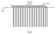
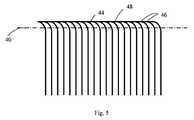
[28] 図4に示された本発明の別の実施形態では、曲線の入口ブライン供給スペーサの特徴を利用することができる。これらの特徴は、入口縁部及び出口縁部に沿って膜リーフの半分に印刷又は堆積することができ、糊線の面積を支持するように十分に遠くまで延在するに過ぎない。要素を回転し接着する間、入口縁部及び出口縁部における湾曲特徴44は、回転中に螺旋状に巻いた要素が回転する際にパターンが隣接した層を支持するように、先端46が互いに接近する、より緊密なパターンを生成する。図5に示された本発明の別の実施形態では、先端46の間の空間はゼロに低減することができ、それによって回転動作中に糊線をより完全に支持する、連続した実線48を作成する。要素の端部がトリムライン40でトリミングされた後、湾曲部のより緊密な間隔は除去され、それにより流体流れを促進するために特徴の間の入口及び出口の間隔が広がり、要素の端部における圧力損失を回避する働きをする。従来の螺旋状に巻いた膜では、ブライン供給空間の中に流れる流体は要素の端部に垂直であり(流れベクトルは中央チューブの軸に平行であり)、流体流れはブライン供給チャネルの端部で積み重なり、それによって流体供給チャネルを遮断する可能性がある。要素の供給端部におけるこの流体の遮断は、要素の中心線からある角度である流れベクトルで一部が迂回される、流量流れを生成することによって軽減することができる。流体がブライン供給空間に入る際に流体のスイープ運動を生成することにより、供給空間に蓄積され得る材料は一掃することができる。図6では、旋回羽根60は、螺旋状に巻いた要素のブライン供給空間チャネルに入ることができる、螺旋状に巻いた要素の端面から流体流れ内の固体を一掃することにより、要素の端部遮断を回避する助けとなるために回転した要素の端部で横流を付与する曲面を有する。図6の図は、螺旋状に巻いた要素が平坦で回転していない図として示されている。一般にこのパターンは中央チューブを中心に巻き付けられるが、図6には概念をより簡単に説明するために示されている。ブライン供給溶液66は、ブライン供給溶液66が螺旋状に巻いた要素の端部に入る際に垂直である(中央チューブの軸に平行である)。旋回羽根60は、螺旋状に巻いた要素の端部を横切る流れパターンを付与し、それによって材料がブライン供給チャネルの端部上に蓄積しないようにする。印刷スペーサ64が要素に入る際、ブライン供給溶液66をブライン供給溶液66の流れベクトルと一致して維持する、湾曲した入口構成要素62が存在する。ブライン供給溶液が膜供給空間に入る際、印刷スペーサ64は、膜要素中央チューブの中心線により平行であるように、ブライン供給溶液66の流れベクトルを位置合わせする働きをする。しかしこれらの印刷スペーサ64は、局所的渦度を促し、螺旋状に巻いた要素のブライン供給空間内の濃度分極を低減するために、様々な形状及び構成を有することができることが先行技術の当業者にはわかるであろう。[28] In another embodiment of the invention shown in FIG. 4, the features of a curved inlet brine feed spacer can be utilized. These features can be printed or deposited on half of the membrane leaf along the inlet and outlet edges and only extend far enough to support the area of the glue line. During rotation and gluing of the elements, the
[29] 特徴は種々の技法によって堆積することができる。オフセット印刷、グラビア印刷、及びスクリーン印刷などの従来の印刷技法が適することが可能であるが、これらの堆積技法では厚さ及び幾何形状に限度がある可能性がある。より厚い特徴は、マイクロ分注、インクジェット印刷、熱溶解積層法、感光性高分子技術、熱溶融高分子によって、又はシートのロール移載若しくは個別の特徴のピックアンドプレースを含むことができる接着剤を使用する適用を介して堆積することができる。[29] Features can be deposited by a variety of techniques. Conventional printing techniques such as offset printing, gravure printing, and screen printing may be suitable, but these deposition techniques may be limited in thickness and geometry. Thicker features can include microdispensing, inkjet printing, hot melt lamination, photopolymer technology, hot melt polymers, or roll transfer of sheets or pick and place of individual features adhesives Can be deposited via application.
[30] 特徴は、分離された流体、及びこれに限定されないが、熱可塑性プラスチック、反応性ポリマ、ワックス、又は樹脂を含む透過担体と互換性がある、あらゆる数の材料から構成することができる。追加として、分離された流体と互換性があるが、これに限定されない、高温熱可塑性プラスチック、金属、又はセラミックを含む膜シートへの直接堆積と互換性がない材料は、適切な寸法に予備形成し、鋳造し、又は切断し、膜シートと互換性がある接着剤で膜シートの表面に接着することができる。[30] The feature may be composed of any number of materials compatible with separated fluids and permeable carriers including, but not limited to, thermoplastics, reactive polymers, waxes, or resins. .. Additionally, materials compatible with separated fluids, but not limited to direct deposition on membrane sheets, including high temperature thermoplastics, metals, or ceramics, are preformed to the appropriate dimensions. It can be cast, cast or cut and adhered to the surface of the membrane sheet with an adhesive compatible with the membrane sheet.
[31] 本発明は、様々な例示的実施形態に関連して記載された。上の記載は本発明の原理の適用の例示に過ぎず、本発明の範囲は本明細書に照らして見た特許請求の範囲によって決定されるべきであることが理解されよう。本発明の他の変形形態及び修正形態が当業者には明らかになろう。
[31] The present invention has been described with reference to various exemplary embodiments. It will be appreciated that the above description is merely an illustration of the application of the principles of the invention, the scope of which is to be determined by the claims which follow in light of this specification. Other variations and modifications of the invention will be apparent to those skilled in the art.
Claims (21)
Translated fromJapanese前記突出部は、前記第1リーフの第1領域内及び前記第2リーフの第1領域内に配置され、(a)前記第1リーフの前記第1領域以外の前記第1リーフの前記活性表面上、(b)前記第2リーフの前記第1領域以外の前記第2リーフの前記活性表面上、又は(c)両方に配置された複数の流れ突出部を更に含み、前記流れ突出部は、前記第1リーフの前記第1領域内の前記突出部の高さ及び前記第2リーフの前記第1領域内の前記突出部の高さの合計にほぼ等しい高さを有し、一方のリーフ上の流れ突出部は、前記濾過要素が螺旋状に巻かれたときに他方のリーフ上の流れ突出部と接触しない、膜。A membrane for use in a spiral wound filtration element comprising a first leaf and a second leaf, each leaf having an active surface, wherein a plurality of protrusions are disposed on saidactive surface, Protrusions areshaped and arranged on theactive surface such that the protrusions contact each otherwhen the active surface of the first leaf is placed adjacent to the active surface of the second leaf, The protrusion on the first leaf is separated from the active surface of the second leaf by the protrusion on the second leaf, the first leaf and the second leaf havingthe active surfaces facing each other. Placed, separated by the protrusions,
The protrusion is arranged in a first region of the first leaf and a first region of the second leaf, and (a) the active surface of the first leaf other than the first region of the first leaf. Top, (b) further comprising a plurality of flow protrusions disposed on the active surface of the second leaf other than the first region of the second leaf, or (c) both, the flow protrusions comprising: On one of the leaves having a height approximately equal to the sum of the height of the protrusion in the first area of the first leaf and the height of the protrusion in the first area of the second leaf The flow protrusions of the membranedo not come into contact with the flow protrusions on the other leaf when the filter element is spirally wound .
それぞれが活性表面を有する第1リーフ及び第2リーフを提供することと、
その第1領域内で各リーフの前記活性表面上に第1の複数の突出部を置くことであって、前記突出部は、前記第1リーフの前記活性表面が前記第2リーフの前記活性表面に隣接して置かれたときに前記突出部が互いに接触するように形作られて前記活性表面上に配置され、前記第1リーフ上の前記突出部は前記第2リーフ上の前記突出部により前記第2リーフの前記活性表面から分離される、置くことと、
(a)前記第1リーフの前記第1領域以外の前記第1リーフの前記活性表面上、(b)前記第2リーフの前記第1領域以外の前記第2リーフの前記活性表面上、又は(c)両方に第2の複数の流れ突出部を置くことであって、前記流れ突出部は、前記第1リーフの前記第1領域内の前記突出部の高さ及び前記第2リーフの前記第1領域内の前記突出部の高さの合計にほぼ等しい高さを有し、一方のリーフ上の流れ突出部は、前記濾過要素が螺旋状に巻かれたときに他方のリーフ上の流れ突出部と接触しない、置くことと、
前記第1リーフの前記活性表面を、前記突出部によって分離された前記第2リーフの前記活性表面に隣接して置くことと、を含む方法。A method of making a membranefor use in a spiral wound filtration element , comprising:
Andthat each providesa first leaf and second leafhaving an active surface,
Placing afirst plurality of protrusions on the active surfaceof each leafwithin its first region , wherein the protrusions are such that the active surface of the first leaf is the active surface of the second leaf. the protrusion is disposed on theactive surface isshaped to contact each otherwhen placed adjacent to the protrusion on the first leaf said by the protrusion on the second leaf Separating from the active surface of the second leaf,
(A) on the active surface of the first leaf other than the first area of the first leaf, (b) on the active surface of the second leaf other than the first area of the second leaf, or ( c) Placing a second plurality of flow protrusions on both, said flow protrusions having a height of said protrusions within said first region of said first leaf and said first protrusion of said second leaf. A flow protrusion on one leaf having a height approximately equal to the sum of the heights of said protrusions in one region, the flow protrusion on one leaf when the filter element is spirally wound. Placing it without touching
Method comprising the active surface of the firstleaf, and a placing adjacent to the separated second leaf of said active surface by the protrusion.
前記突出部は、前記第1リーフ部分の第1領域内及び前記第2リーフ部分の第1領域内に配置され、(a)前記第1リーフ部分の前記第1領域以外の前記第1リーフ部分の前記活性表面上、(b)前記第2リーフ部分の前記第1領域以外の前記第2リーフ部分の前記活性表面上、又は(c)両方に配置された複数の流れ突出部を更に含み、前記流れ突出部は、前記第1リーフ部分の前記第1領域内の前記突出部の高さ及び前記第2リーフ部分の前記第1領域内の前記突出部の高さの合計にほぼ等しい高さを有し、一方のリーフ部分上の流れ突出部は、前記濾過要素が螺旋状に巻かれたときに他方のリーフ上の流れ突出部と接触しない、膜。A membrane for use in filtration element wound helically, wherein the sheet having an active surface, wherein the sheetisa Nde tatami folding the active surface on the inside of the sheet folded thethe first side of the fold line 1 to form a leaf portion and also forms a second leaf portion to a second side of said fold line, said active surfacehas a plurality of protrusions disposed thereon, the protrusions, the protrusionsdisposed on said surfaceshaped to hold apartthe active surfacefacing the sheet folded the contactwith eachother,
The protrusion is arranged in a first region of the first leaf portion and in a first region of the second leaf portion, and (a) the first leaf portion other than the first region of the first leaf portion. Further comprising a plurality of flow protrusions disposed on said active surface of (b) on said active surface of said second leaf portion other than said first region of said second leaf portion, or (c) both. The flow protrusion has a height approximately equal to a sum of a height of the protrusion in the first region of the first leaf portion and a height of the protrusion in the first region of the second leaf portion. A membrane, wherein the flow protrusions on one leaf portion do not contact the flow protrusions on the other leaf when the filter element is spirally wound .
Applications Claiming Priority (3)
| Application Number | Priority Date | Filing Date | Title |
|---|---|---|---|
| US201662424460P | 2016-11-19 | 2016-11-19 | |
| US62/424,460 | 2016-11-19 | ||
| PCT/US2017/062424WO2018094287A1 (en) | 2016-11-19 | 2017-11-17 | Interfernce patterns for spiral-wound elements |
Publications (2)
| Publication Number | Publication Date |
|---|---|
| JP2019535499A JP2019535499A (en) | 2019-12-12 |
| JP6719667B2true JP6719667B2 (en) | 2020-07-08 |
Family
ID=62145817
Family Applications (1)
| Application Number | Title | Priority Date | Filing Date |
|---|---|---|---|
| JP2019522827AActiveJP6719667B2 (en) | 2016-11-19 | 2017-11-17 | Interference pattern for spirally wound elements |
Country Status (6)
| Country | Link |
|---|---|
| US (3) | US10471391B2 (en) |
| EP (1) | EP3541623A4 (en) |
| JP (1) | JP6719667B2 (en) |
| KR (1) | KR102033982B1 (en) |
| CN (1) | CN110248802A (en) |
| WO (2) | WO2018094288A2 (en) |
Families Citing this family (2)
| Publication number | Priority date | Publication date | Assignee | Title |
|---|---|---|---|---|
| US12350627B2 (en) | 2013-02-28 | 2025-07-08 | Aqua Membranes, Inc. | Permeate flow patterns |
| CN109952197A (en) | 2016-09-20 | 2019-06-28 | 阿夸曼布拉尼斯有限责任公司 | Penetrant flows pattern |
Family Cites Families (259)
| Publication number | Priority date | Publication date | Assignee | Title |
|---|---|---|---|---|
| JPS576364B2 (en) | 1974-06-20 | 1982-02-04 | ||
| US3963621A (en) | 1974-10-21 | 1976-06-15 | Baxter Laboratories, Inc. | Membrane diffusion device having ribbed membrane support |
| GB1546529A (en) | 1976-07-13 | 1979-05-23 | Toray Industries | Production of a liquid separation module utilizing semipermeable membranes |
| JPS5371686A (en) | 1976-12-09 | 1978-06-26 | Efu Konerii Robaato | Tubular molecule filtering apparatus |
| US4187173A (en) | 1977-03-28 | 1980-02-05 | Keefer Bowie | Reverse osmosis method and apparatus |
| USRE32144E (en) | 1977-03-28 | 1986-05-13 | Reverse osmosis method and apparatus | |
| DE2802780C2 (en) | 1978-01-23 | 1980-09-18 | Gkss - Forschungszentrum Geesthacht Gmbh, 2000 Hamburg | Device for water desalination and purification by reverse osmosis and ultranitration |
| US4288326A (en) | 1978-03-14 | 1981-09-08 | Keefer Bowie | Rotary shaft driven reverse osmosis method and apparatus |
| ES482466A1 (en) | 1978-07-14 | 1980-06-16 | Steinmueller Gmbh L & C | Reverse osmosis desalinization utilizing plural flow work exchange vessels |
| US4230564A (en) | 1978-07-24 | 1980-10-28 | Keefer Bowie | Rotary reverse osmosis apparatus and method |
| US4208289A (en) | 1978-11-08 | 1980-06-17 | Desalination Systems, Inc. | Reverse osmosis apparatus employing a reciprocating membrane cartridge |
| US4230579A (en) | 1979-01-10 | 1980-10-28 | Desalination Systems, Inc. | Brine flow control for membrane separation system |
| US4434056A (en) | 1979-04-06 | 1984-02-28 | Keefer Bowie | Multi-cylinder reverse osmosis apparatus and method |
| US4235723A (en) | 1979-05-15 | 1980-11-25 | Hydranautics | Reverse osmosis membrane module |
| JPS5628603A (en) | 1979-08-14 | 1981-03-20 | Nitto Electric Ind Co Ltd | Liquid separating device |
| US4341631A (en) | 1979-09-07 | 1982-07-27 | Union Carbide Corporation | Ultrafiltration and reverse osmosis device comprising plural carbon tubes bonded together |
| US4309287A (en) | 1980-05-01 | 1982-01-05 | Abcor, Inc. | Reverse-osmosis tubular membrane |
| US4410429A (en) | 1980-07-07 | 1983-10-18 | Foster-Miller Associates | Linear pocket energy exchange device |
| IL60645A (en) | 1980-07-21 | 1984-02-29 | Cais Michael | Method and device for mass transfer and separation through selective barriers |
| US4358377A (en) | 1980-09-02 | 1982-11-09 | The Dow Chemical Company | Shear-vectoring design for composite casing end and removable, pressure-locking closure therefor |
| US4347132A (en) | 1981-02-17 | 1982-08-31 | Water Refining Company, Inc. | Reverse osmosis expansible pressurized permeate storage having permeate and concentrate controls |
| US4461707A (en) | 1981-10-30 | 1984-07-24 | Canadian Patents & Development Limited | Ultrafiltration and reverse osmosis tubular membrane module |
| US4409849A (en) | 1982-02-10 | 1983-10-18 | Abcor, Inc. | Probe for collecting test permeate from a multiple-membrane module |
| US4454891A (en) | 1982-03-09 | 1984-06-19 | Emerson Electric Co. (H & H Precision Products Division) | Air gap drain module for use in a reverse osmosis system |
| US4426285A (en) | 1982-06-28 | 1984-01-17 | Water Refining Company | Water softening and treatment system |
| US4411785A (en) | 1982-09-29 | 1983-10-25 | Ecodyne Corporation | Reverse osmosis hollow fiber filter element |
| US4600512A (en) | 1982-12-08 | 1986-07-15 | Baxter Travenol Laboratories, Inc. | Reverse osmosis water purification module |
| US4585554A (en) | 1983-01-13 | 1986-04-29 | Burrows Bruce D | Combined purified water dispensing device and reject water control device |
| US4476022A (en) | 1983-03-11 | 1984-10-09 | Doll David W | Spirally wrapped reverse osmosis membrane cell |
| US4482459A (en) | 1983-04-27 | 1984-11-13 | Newpark Waste Treatment Systems Inc. | Continuous process for the reclamation of waste drilling fluids |
| US4735718A (en) | 1983-05-04 | 1988-04-05 | Millipore Corporation | Multilayer membrane separator |
| DE3317517C2 (en) | 1983-05-13 | 1985-03-21 | Gkss - Forschungszentrum Geesthacht Gmbh, 2054 Geesthacht | Device for filtering and separating liquid and gaseous media |
| US4874514A (en) | 1983-12-30 | 1989-10-17 | Wetco Of Delaware, Inc. | Tubular element for reverse osmosis water pruification |
| ATE68991T1 (en) | 1984-06-13 | 1991-11-15 | Inst Nat Rech Chimique | PROCESSES FOR THE PRODUCTION OF HOLLOW FIBERS AND THEIR USE IN MEMBRANE SEPARATION PROCESSES. |
| FR2566282B1 (en) | 1984-06-20 | 1989-07-28 | Ceraver | DEVICE FOR ASSEMBLING A TUBULAR FILTERING ELEMENT IN AN ENCLOSURE |
| US4623467A (en) | 1984-06-25 | 1986-11-18 | International Manufacturing And Water Vending Company | Water purifying and vending apparatus |
| US5507943A (en) | 1984-07-19 | 1996-04-16 | Labrador; Gaudencio A. | Water-wave energy converter systems |
| US4595497A (en) | 1984-07-23 | 1986-06-17 | Burrows Bruce D | Purified water reverse osmosis reservoir |
| US4743366A (en) | 1984-07-23 | 1988-05-10 | Burrows Bruce D | Control valve assembly for purified water supply system |
| US4599171A (en) | 1984-07-30 | 1986-07-08 | Pure Water International, Inc. | Water purifier fitting and system |
| US4534713A (en) | 1984-08-10 | 1985-08-13 | Wanner William F | Pump apparatus |
| USRE33135E (en) | 1984-08-10 | 1989-12-26 | Recovery Engineering | Pump apparatus |
| US4645601A (en) | 1984-08-31 | 1987-02-24 | Everpure, Inc. | Quick change reverse osmosis assembly |
| US4670144A (en) | 1984-10-23 | 1987-06-02 | Nature's Sunshine Products, Inc. | Portable water purification system |
| US4613436A (en) | 1984-10-31 | 1986-09-23 | Separex Corporation | Membrane assembly for fluid separations-disk |
| US4775465A (en) | 1984-12-24 | 1988-10-04 | Burrows Bruce D | Reverse osmosis assembly operating valve |
| US4657674A (en) | 1984-12-24 | 1987-04-14 | Burrows Bruce D | Reverse osmosis assembly including an operating valve |
| US4830744A (en) | 1984-12-24 | 1989-05-16 | Burrows Bruce D | Reverse osmosis assembly operating valve |
| US4623451A (en) | 1985-02-19 | 1986-11-18 | Oliver Bruce J | Third faucet system with above sink purity indicator |
| US4704324A (en) | 1985-04-03 | 1987-11-03 | The Dow Chemical Company | Semi-permeable membranes prepared via reaction of cationic groups with nucleophilic groups |
| US4608140A (en) | 1985-06-10 | 1986-08-26 | Ionics, Incorporated | Electrodialysis apparatus and process |
| US4705625A (en) | 1985-10-31 | 1987-11-10 | Hart Jr John E | Reverse osmosis water purifying system |
| US4744895A (en) | 1985-11-08 | 1988-05-17 | Aquasciences International, Inc. | Reverse osmosis water purifier |
| US4877521A (en) | 1987-04-30 | 1989-10-31 | Cuno, Incorporated | Quick-change filter cartridge and head therefor |
| US4735716A (en) | 1986-01-27 | 1988-04-05 | Cuno Corporated | Quick-change filter cartridge and head therefor |
| US4652373A (en) | 1986-02-21 | 1987-03-24 | The Dow Chemical Company | Tubesheet for spiral wound hollow fiber permeator |
| US4856559A (en) | 1986-03-21 | 1989-08-15 | Aquathin Corp. | Faucet providing and utilizing air gap |
| US4885092A (en) | 1986-03-24 | 1989-12-05 | American Cyanamid | Process for the manufacture of asymmetric, porous membranes and product thereof |
| FR2598629B1 (en) | 1986-05-16 | 1990-10-19 | Lopez Fernand | MODULE FOR FILTERING A PRESSURIZED LIQUID |
| US4695375A (en) | 1986-05-27 | 1987-09-22 | Tyler Truman V | Self-contained hydraulically operable water purifier |
| US4855058A (en) | 1986-06-24 | 1989-08-08 | Hydranautics | High recovery spiral wound membrane element |
| US4756835A (en) | 1986-08-29 | 1988-07-12 | Advanced Polymer Technology, Inc. | Permeable membranes having high flux-density and low fouling-propensity |
| US4781831A (en) | 1986-12-19 | 1988-11-01 | Goldsmith Robert L | Cross-flow filtration device with filtrate flow conduits and method of forming same |
| US4741823A (en) | 1986-12-23 | 1988-05-03 | Osmonics, Inc. | Flow control manifold for cross-flow membrane system |
| US4744900A (en) | 1987-04-20 | 1988-05-17 | Bratt Russell I | Reverse osmosis membrane container |
| DE3715183A1 (en) | 1987-05-07 | 1988-11-17 | Juergen Mohn | DISTANCE ELEMENT FOR GUIDING FLOW MEDIA |
| DE3886053T2 (en) | 1987-05-29 | 1994-04-07 | Terumo Corp | Body fluid filters with permeable flat film membranes having protruding parts. |
| US4990248A (en) | 1987-06-03 | 1991-02-05 | Eastman Kodak Company | Reverse osmosis apparatus |
| DE3719292C1 (en) | 1987-06-10 | 1988-12-29 | Grundfos Internat A S | Pump device for the treatment of raw water according to the principle of reverse osmosis |
| US4844805A (en) | 1987-07-17 | 1989-07-04 | Wetco Of Delaware, Inc. | Reverse osmosis element |
| US4917847A (en) | 1987-07-17 | 1990-04-17 | Wetco Of Delaware, Inc. | Method of making a reverse osmosis element |
| US4784771A (en) | 1987-08-03 | 1988-11-15 | Environmental Water Technology, Inc. | Method and apparatus for purifying fluids |
| US4834881A (en) | 1987-08-19 | 1989-05-30 | Kurita Water Industries Ltd. | Spiral wound type membrane module |
| CH676676A5 (en) | 1987-08-28 | 1991-02-28 | Bucher Guyer Ag Masch | |
| CA1290700C (en) | 1987-09-24 | 1991-10-15 | Geoffrey W. Vickers | Centrifugal reverse-osmosis desalination unit |
| US4802982A (en) | 1987-10-01 | 1989-02-07 | Desalination Systems, Inc. | Spiral-wound membrane with improved permeate carrier |
| DE3803886A1 (en) | 1988-02-09 | 1989-08-10 | Geesthacht Gkss Forschung | DEVICE FOR FILTERING AND SEPARATING FLUID MEDIA |
| US4814079A (en) | 1988-04-04 | 1989-03-21 | Aqua-Chem, Inc. | Spirally wrapped reverse osmosis membrane cell |
| US4869821A (en) | 1988-04-28 | 1989-09-26 | W. R. Grace & Co.-Conn. | Drainage disc for membrane assembly |
| US4876002A (en) | 1988-06-13 | 1989-10-24 | Schlumberger Industries, Inc. | Reverse osmosis water purificaiton unit |
| US4902417A (en)* | 1988-06-14 | 1990-02-20 | Desalination Systems, Inc. | Spiral-wound membrane cartridge with ribbed and spaced carrier layer |
| US4834873A (en) | 1988-08-17 | 1989-05-30 | Burrows Bruce D | Combined reverse osmosis unit and water inflow control valve for a water purification system |
| US4842736A (en)* | 1988-09-06 | 1989-06-27 | Desalination Systems, Inc. | Spiral wound membrane |
| US4882061A (en) | 1989-01-23 | 1989-11-21 | Cuno, Incorporated | Filter apparatus |
| US4861487A (en) | 1989-02-08 | 1989-08-29 | Fulk Jr Clyde W | Spiral wound membrane modules and systems with improved feed spacer |
| DE3915197C2 (en) | 1989-05-10 | 1993-10-07 | Dt Membranfilter Vertrieb | Spacer for directing flow media |
| US4906372A (en) | 1989-05-17 | 1990-03-06 | Desalination Systems, Inc. | Spiral-wound membrane cartridge |
| US5104532A (en) | 1989-09-15 | 1992-04-14 | Exxon Research And Engineering Company | Flat stack permeator |
| US4944877A (en) | 1989-10-10 | 1990-07-31 | Maples Paul D | Spacerless feed channel membrane filter element |
| US4937557A (en) | 1990-01-02 | 1990-06-26 | Aqua-Tronics, Inc. | Monitoring and indicating circuit for reverse osmosis filter |
| US5096574A (en) | 1990-01-16 | 1992-03-17 | Teledyne Industries, Inc. | Reverse osmosis system |
| US5132017A (en) | 1990-01-16 | 1992-07-21 | Teledyne Industries, Inc. | Reverse osmosis system |
| US5131277A (en) | 1990-01-16 | 1992-07-21 | Teledyne Industries, Inc. | Reverse osmosis system |
| US5078876A (en) | 1990-01-17 | 1992-01-07 | Trysan Research, Inc. | Apparatus for multistage purification of water |
| US5057212A (en) | 1990-03-09 | 1991-10-15 | Burrows Bruce D | Water conductivity monitor and circuit with extended operating life |
| US5145575A (en) | 1990-03-09 | 1992-09-08 | Burrows Bruce D | Water quality monitor for a water purification system |
| US5354464A (en) | 1990-03-14 | 1994-10-11 | Water Factory Systems | Multi-port connecting device |
| US5002664A (en) | 1990-03-15 | 1991-03-26 | Clack Corporation | Fluid flow control device for R.O. filtration purification systems |
| US5128035A (en) | 1990-03-15 | 1992-07-07 | Clack Corporation | Fluid flow control device for water treatment systems |
| US4992170A (en) | 1990-04-03 | 1991-02-12 | Eastman Kodak Company | Reverse osmosis filter cartridge assembly |
| US5017284A (en) | 1990-04-27 | 1991-05-21 | Environmental Water Technology, Inc. | Fluid purifying apparatus and method of purifying fluids |
| US5043066A (en) | 1990-04-27 | 1991-08-27 | Environmental Water Technology, Inc. | Fluid purifying apparatus and method of purifying fluids |
| US5198110A (en) | 1990-07-02 | 1993-03-30 | Asahi Medical Co., Ltd. | Bundle of permselective hollow fibers and a fluid separator containing the same |
| US5045197A (en) | 1990-08-03 | 1991-09-03 | Burrows Bruce D | Reverse osmosis purification system with unitary header manifold |
| US5167786A (en) | 1991-01-25 | 1992-12-01 | Eberle William J | Wave-power collection apparatus |
| FR2672513B1 (en) | 1991-02-13 | 1994-03-18 | Tech Sep | IMPROVED METHOD AND MODULE FOR FILTERING IN A LIQUID MEDIUM UNDER INSTANTANEOUS TANGENTIAL FLOW. |
| WO1992014838A1 (en) | 1991-02-13 | 1992-09-03 | Nihon Millipore Kogyo Kabushiki Kaisha | Method of determining viable count |
| US5167826A (en) | 1991-07-03 | 1992-12-01 | Stanadyne Automotive Corp. | Engine collant recycling apparatus and process |
| US5234583A (en) | 1991-07-26 | 1993-08-10 | Cluff C Brent | Semi-permeable membrane filtering systems for swimming pools |
| US5108604A (en) | 1991-08-23 | 1992-04-28 | Desalination Systems, Inc. | Semipermeable membrane cartridge and method of making |
| DE4130481C2 (en) | 1991-09-13 | 1995-03-09 | Dt Membranfilter Vertrieb | Device with housing for filtering and separating flow media |
| US5194156A (en) | 1991-10-18 | 1993-03-16 | Tomchak Sigfrid A | Water purifier faucet fitting |
| US5279732A (en) | 1992-03-23 | 1994-01-18 | Edens Jeffrey I | Fluid conditioning device |
| US5204002A (en) | 1992-06-24 | 1993-04-20 | Rensselaer Polytechnic Institute | Curved channel membrane filtration |
| US5427682A (en) | 1992-09-17 | 1995-06-27 | J. Vogel Premium Water Co. | Water purification and dispensing system |
| US5468387A (en) | 1992-12-30 | 1995-11-21 | Solomon; Donald F. | Storage tank and reverse osmosis system utilizing the same |
| US5232591A (en) | 1992-12-30 | 1993-08-03 | Solomon Donald F | Storage tank and reverse osmosis system utilizing the same |
| US5362383A (en) | 1993-01-13 | 1994-11-08 | Ecowater Systems, Inc. | Self-contained reverse osmosis electronic monitoring system |
| US5296148A (en) | 1993-03-16 | 1994-03-22 | Nimbus Water Systems, Inc. | Reverse osmosis water purifier |
| US5573662A (en) | 1993-09-13 | 1996-11-12 | Nomura Micro Science Co., Ltd. | Apparatus for treatment of low-concentration organic waste water |
| US5466366A (en) | 1994-02-01 | 1995-11-14 | New Gulf Measurement Instrument Ltd. Company | Water temperature and conductivity detector for reverse-osmosis water purifier systems |
| DE4405175C2 (en) | 1994-02-18 | 1997-04-24 | Dt Membranfilter Vertrieb | Device for filtering and separating flow media by means of filter elements designed in the manner of membrane cushions |
| US5681459A (en) | 1994-03-07 | 1997-10-28 | Bowman; Dennis E. | Refect water drain line installation system and apparatus for under sink reverse osmosis filter system |
| EP0707884B1 (en) | 1994-10-21 | 2001-06-13 | Rochem Ultrafiltrations Systeme Gesellschaft für Abwasserreinigung mbH | Filtration and separation apparatus, especially for biological-organic fluids with filter elements in the form of membrane pads |
| US5462414A (en) | 1995-01-19 | 1995-10-31 | Permar; Clark | Liquid treatment apparatus for providing a flow of pressurized liquid |
| AU700335B2 (en) | 1995-03-22 | 1998-12-24 | Mechano Chemical Research Institute Ltd. | Method for desalinating salts-containing water and apparatus therefor |
| WO1996029133A1 (en) | 1995-03-23 | 1996-09-26 | Ionics, Incorporated | Improvements in membrane processes including electrodialysis |
| US5626758A (en) | 1995-08-08 | 1997-05-06 | Rensselaer Polytechnic Institute | Coiled membrane filtration system |
| DE19544960A1 (en) | 1995-12-04 | 1997-06-05 | Aloys Wobben | Device for filtering and separating flow media |
| US5824217A (en) | 1996-03-27 | 1998-10-20 | Millipore Corporation | Membrane filtration apparatus |
| JP3430783B2 (en) | 1996-04-11 | 2003-07-28 | 東レ株式会社 | Liquid separation element, apparatus and processing method |
| JP2887105B2 (en) | 1996-04-24 | 1999-04-26 | 幸子 林 | Method and apparatus for producing drinking water and salt |
| US5788858A (en) | 1996-05-03 | 1998-08-04 | Terra Group, Inc. | Mobile water purification unit with modular dechlorination input stage |
| US5628198A (en) | 1996-05-13 | 1997-05-13 | Permar; Clark | Liquid treatment apparatus for filtering liquid under pressure |
| JP4471240B2 (en) | 1996-05-31 | 2010-06-02 | ダブリューエム インターナショナル リミテッド | Improved water treatment system |
| US5795475A (en) | 1996-07-12 | 1998-08-18 | Neoperl, Inc. | Coupler/diverter for counter-top RO filter |
| US6378907B1 (en) | 1996-07-12 | 2002-04-30 | Mykrolis Corporation | Connector apparatus and system including connector apparatus |
| US5914041A (en) | 1996-09-03 | 1999-06-22 | Nate International | Channel based reverse osmosis |
| US5681467A (en) | 1996-09-19 | 1997-10-28 | The Dow Chemical Company | Method for forming a membrane into a predetermined shape |
| US6190557B1 (en) | 1996-12-09 | 2001-02-20 | Nitto Denko Corporation | Spiral wound type membrane element, running method and washing method thereof |
| DE19700231C2 (en) | 1997-01-07 | 2001-10-04 | Geesthacht Gkss Forschung | Device for filtering and separating flow media |
| MA26028A1 (en) | 1997-01-09 | 2004-04-01 | Garfield Int Invest Ltd | DESALINATION OF WATER |
| CA2196224C (en) | 1997-01-29 | 2003-07-01 | Gerald John Vowles | Wave energy generator |
| JP3669512B2 (en) | 1997-04-14 | 2005-07-06 | ネイト・インターナショナル | Modular filtration system |
| JP3477526B2 (en) | 1997-05-27 | 2003-12-10 | 日立造船株式会社 | Wastewater recovery equipment |
| US5985146A (en) | 1997-07-23 | 1999-11-16 | Trisep Corporation | Sanitary rigid shell spiral wound element |
| FR2771305B1 (en) | 1997-11-26 | 2000-02-11 | Dit Zhitariouk Nikol Jitariouk | APPARATUS, SYSTEM AND METHOD FOR SEPARATING LIQUIDS |
| DE19819620C2 (en) | 1998-05-04 | 2002-01-24 | Dengler Hermann | Device for obtaining a desalted solution |
| US6099735A (en) | 1998-06-04 | 2000-08-08 | Kelada; Maher I. | Counter top reverse osmosis water purification system |
| WO2000000268A1 (en) | 1998-06-29 | 2000-01-06 | Microban Products Company | Antimicrobial semi-permeable membranes |
| PT1095693E (en) | 1998-06-30 | 2005-04-29 | Barreto Avero Manuel | INSTALLATION OF WATER DESSALINIZATION BY REVERSE OSMOSIS WITH CONTINUOUS KINETIC CYCLE PRESSURIZED CHANNELS |
| US6071404A (en) | 1998-08-31 | 2000-06-06 | Tsui; Tommy | Water treating device |
| US6110360A (en) | 1998-09-04 | 2000-08-29 | Hart, Jr.; John E. | Low pressure reverse osmosis water purifying system |
| US6120682A (en) | 1998-10-02 | 2000-09-19 | Cook; James E. | Portable pump-type reverse osmosis apparatus |
| JP2000271460A (en) | 1999-01-22 | 2000-10-03 | Nitto Denko Corp | Processing system and processing method using spiral membrane module |
| US6345961B1 (en) | 1999-01-26 | 2002-02-12 | Fluid Equipment Development Company | Hydraulic energy recovery device |
| US6284124B1 (en) | 1999-01-29 | 2001-09-04 | United States Filter Corporation | Electrodeionization apparatus and method |
| US6126833A (en) | 1999-02-22 | 2000-10-03 | Ceramem Corporation | Cross-flow filtration device with filtrate conduit network and method of making same |
| JP2002539933A (en) | 1999-03-25 | 2002-11-26 | テクノロジィ ファイナンス コーポレイション(プロプライエタリー) リミテッド | Filtration system suitable for microfiltration, ultrafiltration or reverse osmosis |
| EP1214137B1 (en) | 1999-04-07 | 2005-03-23 | Kenneth R. Bosley | Seawater pressure-driven desalinization apparatus and method with gravity-driven brine return |
| US7244357B2 (en) | 1999-05-25 | 2007-07-17 | Miox Corporation | Pumps for filtration systems |
| US7297268B2 (en) | 1999-05-25 | 2007-11-20 | Miox Corporation | Dual head pump driven filtration system |
| US6383384B1 (en) | 1999-07-06 | 2002-05-07 | Clifton Gerard Anderson | Reverse osmosis water purifier |
| US6379518B1 (en) | 1999-08-11 | 2002-04-30 | Kurita Water Industries Ltd. | Electrodeionization apparatus and pure water producing apparatus |
| US6632357B1 (en) | 1999-11-18 | 2003-10-14 | University Of South Florida | Reverse osmosis (“RO”) membrane system incorporating function of flow channel spacer |
| GB2357320B (en) | 1999-12-15 | 2004-03-24 | Calder Ltd | Energy recovery device |
| JP2001239140A (en) | 1999-12-22 | 2001-09-04 | Reika Kogyo Kk | Reaction stirrer, reaction fractionation filtration device and fractionation method, production method, filtration method |
| DE10000186C2 (en) | 2000-01-05 | 2003-09-04 | Sartorius Gmbh | Device and system for crossflow filtration |
| ATE308374T1 (en) | 2000-04-20 | 2005-11-15 | Rochem Ultrafiltrations System | DEVICE FOR FILTERING AND SEPARATING PARTICULARLY BIOLOGICAL ORGANIC FLOW MEDIA |
| US6299766B1 (en) | 2000-07-06 | 2001-10-09 | Clark Permar | Reverse osmosis filtering apparatus with concentrate dilution |
| US6436282B1 (en) | 2000-08-08 | 2002-08-20 | Plymouth Products, Inc. | Flow control module for RO water treatment system |
| US6423223B1 (en) | 2000-08-31 | 2002-07-23 | Donald A. Northcut | Multi-element, reverse osmosis, liquid filter system with flushing and filtering circuits |
| US6521124B2 (en) | 2000-08-31 | 2003-02-18 | Donald A. Northcut | Reverse osmosis liquid filter system with ultraviolet filtration |
| AU2001219539A1 (en)* | 2000-09-05 | 2002-03-22 | Wesley L. Bradford | Reverse osmosis membrane and process for making same |
| WO2002055179A1 (en) | 2001-01-12 | 2002-07-18 | Werner Frei | Method for producing a foldable filter and products of said method |
| US6423212B1 (en) | 2001-01-31 | 2002-07-23 | Lancer Partnership Ltd. | Microbial resistant water purification and collection system |
| US6805796B2 (en) | 2001-02-13 | 2004-10-19 | Nitto Denko Corporation | Water treatment apparatus |
| US7186331B2 (en) | 2001-03-06 | 2007-03-06 | Sasol Technology (Pty) Limited | Monitoring unit for monitoring the condition of a semi-permeable membrane |
| US6790345B2 (en) | 2001-07-16 | 2004-09-14 | Ronney L. Broussard | Underwater filtration operator |
| US6632356B2 (en)* | 2001-08-01 | 2003-10-14 | Dow Global Technologies Inc. | Separation membrane end cap |
| US6607668B2 (en) | 2001-08-17 | 2003-08-19 | Technology Ventures, Inc. | Water purifier |
| NL1019374C2 (en) | 2001-11-15 | 2003-05-16 | Norit Holding N V | Method for manufacturing a filter module, such a filter module, whether or not included in a filter system. |
| US6830683B2 (en) | 2002-04-23 | 2004-12-14 | Culligan International Company | Filter cartridge assembly with brine seal and retaining ring |
| US8147699B2 (en) | 2002-08-21 | 2012-04-03 | Hpd, Llc | Monolith filter apparatus and membrane apparatus, and method using same |
| FR2845082B1 (en) | 2002-09-26 | 2006-02-10 | Millipore Corp | MODULE FOR PURIFYING A FLUID, IN PARTICULAR WATER |
| US7455778B2 (en) | 2002-10-08 | 2008-11-25 | Water Standard Company Llc | Intake for water desalination systems, and methods of use |
| US7416666B2 (en) | 2002-10-08 | 2008-08-26 | Water Standard Company | Mobile desalination plants and systems, and methods for producing desalinated water |
| DE10253483A1 (en) | 2002-11-18 | 2004-05-27 | Bayer Ag | Assembly for membrane electrophoresis of dissolved/dispersed substances using micro filtration membranes, maintains a pressure difference at the membranes to reduce electro osmotic flows |
| JP4454502B2 (en) | 2002-12-27 | 2010-04-21 | 荏原エンジニアリングサービス株式会社 | Electric desalination equipment |
| US6929748B2 (en) | 2003-03-28 | 2005-08-16 | Chemitreat Pte Ltd | Apparatus and method for continuous electrodeionization |
| TWI245163B (en) | 2003-08-29 | 2005-12-11 | Asml Netherlands Bv | Lithographic apparatus and device manufacturing method |
| WO2005068371A1 (en) | 2004-01-15 | 2005-07-28 | Desaln8 Pty Ltd. | Water desalination |
| CA2572889C (en) | 2004-07-05 | 2010-10-12 | Picogram Co., Ltd. | One-touch fitting type single or multiple adapter, filter assembly detachably engaged with the same and water purifying system employing these elements |
| WO2006020679A2 (en) | 2004-08-10 | 2006-02-23 | Leif Hauge | Pressure exchanger |
| WO2006040175A1 (en) | 2004-10-15 | 2006-04-20 | Pall Corporation | Spacer for filter modules |
| NZ554561A (en) | 2004-10-20 | 2011-02-25 | Alfa Laval Corp Ab | Permeate Tube |
| US7341663B2 (en) | 2004-12-16 | 2008-03-11 | The United States Of America As Represented By The Secretary Of Agriculture | Spiral-wound liquid membrane module for separation of fluids and gases |
| US7501064B2 (en) | 2005-01-06 | 2009-03-10 | Eet | Integrated electro-pressure membrane deionization system |
| DK2201995T3 (en) | 2005-01-27 | 2018-10-01 | Ecowater Systems Llc | Method for regulating a reverse osmosis water treatment system |
| JP2008100123A (en) | 2005-07-07 | 2008-05-01 | Koichi Kawakami | Water treatment apparatus |
| US7875184B2 (en) | 2005-09-22 | 2011-01-25 | Eastman Chemical Company | Crystallized pellet/liquid separator |
| US7650805B2 (en) | 2005-10-11 | 2010-01-26 | Millipore Corporation | Integrity testable multilayered filter device |
| US7927082B2 (en) | 2005-12-05 | 2011-04-19 | Gth Water Systems, Inc. | Highly efficient durable fluid pump and method |
| JP2009524521A (en) | 2006-01-24 | 2009-07-02 | ザ リージェンツ オブ ザ ユニヴァーシティー オブ カリフォルニア | Method and system for monitoring reverse osmosis membranes |
| NO20071748L (en) | 2006-04-06 | 2007-10-08 | Christ Water Technology Ag | Device for continuous electrochemical desalination with integrated membrane interval. |
| JP5030465B2 (en)* | 2006-04-24 | 2012-09-19 | 日東電工株式会社 | Sealing material holding member for membrane element and membrane element |
| US7514010B2 (en) | 2007-03-08 | 2009-04-07 | Salmon Daniel J | Water filtering method and apparatus |
| US8425734B2 (en) | 2007-07-02 | 2013-04-23 | I3 Nanotec Llc | Membrane-based hybrid process for separation of mixtures of organics, solids, and water |
| JP5369278B2 (en) | 2007-07-03 | 2013-12-18 | 住友電気工業株式会社 | Flat membrane element for filtration and flat membrane filtration module |
| EP2183299A1 (en) | 2007-08-20 | 2010-05-12 | Technion Research and Development Foundation, Ltd. | Polysulfone polymers and membranes for reverse osmosis, nanofiltration and ultrafiltration |
| BRPI0817376B1 (en)* | 2007-09-12 | 2019-05-14 | Danisco Us Inc. | FILTERING SYSTEM WITH INTERNAL INCRUSTATION CONTROL |
| US8292088B2 (en) | 2007-10-17 | 2012-10-23 | Acuity/Sparkle, Ltd. (Cayman) | Water supply system with filtration and retrofit assembly |
| US8147692B2 (en) | 2008-01-04 | 2012-04-03 | Fluid Equipment Development Company, Llc | Batch-operated reverse osmosis system with multiple membranes in a pressure vessel |
| US7892429B2 (en) | 2008-01-28 | 2011-02-22 | Fluid Equipment Development Company, Llc | Batch-operated reverse osmosis system with manual energization |
| US8257594B2 (en) | 2008-02-07 | 2012-09-04 | 3M Innovative Properties Company | Twin tank water-on-water filtration system |
| US7540956B1 (en) | 2008-03-21 | 2009-06-02 | Pentair Filtration, Inc. | Modular drinking water filtration system with removable and replaceable RO spindle |
| EP2352576B1 (en) | 2008-09-29 | 2013-05-29 | Scott P. Yaeger | Spiral wound crossflow filter |
| US9114365B2 (en) | 2008-10-09 | 2015-08-25 | Watts Water Technologies, Inc. | Shut off valve for a reverse osmosis water filtration system |
| US8021550B2 (en) | 2008-10-17 | 2011-09-20 | General Electric Company | Central core element for a separator assembly |
| US8961790B2 (en) | 2008-10-17 | 2015-02-24 | General Electric Company | Separator assembly |
| US8968566B2 (en) | 2008-10-17 | 2015-03-03 | General Electric Company | Separator assembly |
| JP5361325B2 (en) | 2008-10-17 | 2013-12-04 | 有限会社スプリング | Dissolved hydrogen drinking water manufacturing apparatus and manufacturing method thereof |
| JP2010099590A (en) | 2008-10-23 | 2010-05-06 | Nitto Denko Corp | Sheet-like composite semi-permeable membrane and manufacturing method therefor |
| DE102008043422B3 (en) | 2008-11-03 | 2010-01-07 | Evonik Degussa Gmbh | Process for the purification of low molecular weight hydridosilanes |
| US7862723B2 (en) | 2008-11-07 | 2011-01-04 | The Good Water Company, Inc. | Reverse osmosis system |
| US8292492B2 (en) | 2008-11-11 | 2012-10-23 | Sandia Corporation | Airfoil-shaped micro-mixers for reducing fouling on membrane surfaces |
| US7981293B2 (en) | 2008-11-21 | 2011-07-19 | Scott W. Powell | Method and apparatus for treatment of contaminated liquid |
| JP2010125418A (en)* | 2008-11-28 | 2010-06-10 | Nitto Denko Corp | Sheet-like separation membrane and separation membrane element |
| JP2012518538A (en)* | 2009-02-25 | 2012-08-16 | プラット アンド ホイットニー ロケットダイン,インコーポレイテッド | Fluid separation system with reduced fouling |
| JP5964541B2 (en) | 2009-05-15 | 2016-08-03 | 株式会社荏原製作所 | Seawater desalination system and energy exchange chamber |
| US7901580B2 (en) | 2009-06-09 | 2011-03-08 | Salyer Ival O | Method, apparatus, and processes for producing potable water utilizing reverse osmosis at ocean depth in combination with shipboard moisture dehumidification |
| US8506685B2 (en) | 2009-08-17 | 2013-08-13 | Celgard Llc | High pressure liquid degassing membrane contactors and methods of manufacturing and use |
| WO2011094236A2 (en)* | 2010-02-01 | 2011-08-04 | Rodney Herrington | Systems and methods for filtration |
| MX2012008953A (en) | 2010-02-04 | 2012-11-23 | Dxv Water Technologies Llc | Water treatment systems and methods. |
| US9731984B2 (en) | 2010-02-19 | 2017-08-15 | Topper Manufacturing Corporation | Reverse osmosis systems with built in pressure regulation |
| US8282823B2 (en) | 2010-03-04 | 2012-10-09 | Terragroup Corporation | Lightweight modular water purification system with reconfigurable pump power options |
| PT2560811T (en) | 2010-04-20 | 2023-03-29 | Fibracast Ltd | Formed sheet membrane element and filtration system |
| US9387445B2 (en) | 2010-06-03 | 2016-07-12 | Toray Industries, Inc. | Separation membrane element |
| US8696904B2 (en) | 2010-10-28 | 2014-04-15 | General Electric Company | Multi-leaf reverse osmosis element |
| CN103282105A (en) | 2010-12-28 | 2013-09-04 | 东丽株式会社 | Separation membrane element |
| JP5571005B2 (en) | 2011-01-12 | 2014-08-13 | 株式会社クボタ | Pressure exchange device and performance adjustment method of pressure exchange device |
| TW201247297A (en) | 2011-03-29 | 2012-12-01 | Toray Industries | Spiral type separation membrane element and method for producing the same |
| CN102743974B (en) | 2011-04-22 | 2016-01-27 | 株式会社荏原制作所 | Seawater desalination system and energy exchange chamber |
| JP6111668B2 (en) | 2011-07-07 | 2017-04-12 | 東レ株式会社 | Separation membrane element and method for producing separation membrane element |
| US9475008B2 (en) | 2011-08-12 | 2016-10-25 | Amir Salama | Semipermeable filtration membrane with integrated producing circuit |
| EP2762730B1 (en) | 2011-09-30 | 2019-08-07 | Kubota Corporation | Pressure exchange device |
| CN103987446A (en)* | 2011-12-02 | 2014-08-13 | 东丽株式会社 | Separation membrane element and method for manufacturing separation membrane element |
| US20130146532A1 (en)* | 2011-12-09 | 2013-06-13 | General Electric Company | Feed spacer for spiral wound membrane element |
| US9724646B2 (en) | 2012-06-28 | 2017-08-08 | Toray Industries, Inc. | Separation membrane element |
| BR112015020766A2 (en)* | 2013-02-28 | 2017-07-18 | Aqua Membranes Llc | laminated composition, membrane for incorporation into a laminated composition, permeable membrane system, method of producing a suitable laminated composition, method for producing a waterproof membrane system, and method of separating a fluid using a membrane system |
| JPWO2015016253A1 (en) | 2013-07-30 | 2017-03-02 | 東レ株式会社 | Separation membrane element |
| US9403125B2 (en) | 2013-10-08 | 2016-08-02 | Haier Us Appliance Solutions, Inc. | Valve with air-gap provision to prevent backflow |
| JP5804172B2 (en) | 2013-10-23 | 2015-11-04 | ダイキン工業株式会社 | Embossed filter material for air filter, filter pack, air filter unit, and method for producing embossed filter material for air filter |
| CN105658312B (en) | 2013-10-31 | 2018-04-20 | 东丽株式会社 | Separating film element |
| EP2902094B1 (en) | 2014-01-30 | 2024-06-26 | HurraH S.à r.l. | Filtration membrane |
| US9758389B2 (en) | 2015-03-23 | 2017-09-12 | Eco Squared Solutions, Inc | System for separating contaminants from fluids |
| KR102021813B1 (en) | 2015-06-11 | 2019-09-17 | 미쓰비시덴키 가부시키가이샤 | Ground fault overvoltage relay |
| KR20210007048A (en) | 2015-11-19 | 2021-01-19 | 엔테그리스, 아이엔씨. | Features on a porous membrane |
| US9617172B1 (en) | 2016-06-10 | 2017-04-11 | Henry A Baski | Desalination system and method for producing freshwater by reverse osmosis of seawater |
- 2017
- 2017-11-17JPJP2019522827Apatent/JP6719667B2/enactiveActive
- 2017-11-17CNCN201780071166.4Apatent/CN110248802A/enactivePending
- 2017-11-17USUS16/072,962patent/US10471391B2/enactiveActive
- 2017-11-17EPEP17872447.2Apatent/EP3541623A4/enactivePending
- 2017-11-17KRKR1020197014046Apatent/KR102033982B1/enactiveActive
- 2017-11-17WOPCT/US2017/062425patent/WO2018094288A2/ennot_activeCeased
- 2017-11-17WOPCT/US2017/062424patent/WO2018094287A1/ennot_activeCeased
- 2017-11-17USUS16/071,567patent/US11040311B2/enactiveActive
- 2021
- 2021-05-11USUS17/317,063patent/US20210268444A1/ennot_activeAbandoned
Also Published As
| Publication number | Publication date |
|---|---|
| US20190262776A1 (en) | 2019-08-29 |
| WO2018094288A3 (en) | 2019-08-22 |
| JP2019535499A (en) | 2019-12-12 |
| WO2018094287A1 (en) | 2018-05-24 |
| KR102033982B1 (en) | 2019-10-18 |
| CN110248802A (en) | 2019-09-17 |
| EP3541623A4 (en) | 2020-06-24 |
| US20210268444A1 (en) | 2021-09-02 |
| US10471391B2 (en) | 2019-11-12 |
| US20190030488A1 (en) | 2019-01-31 |
| US11040311B2 (en) | 2021-06-22 |
| WO2018094288A2 (en) | 2018-05-24 |
| EP3541623A1 (en) | 2019-09-25 |
| KR20190061087A (en) | 2019-06-04 |
Similar Documents
| Publication | Publication Date | Title |
|---|---|---|
| US20230113186A1 (en) | Spiral Wound Element Construction | |
| US20210268444A1 (en) | Interference patterns for spiral-wound elements | |
| JP2020536725A (en) | Bridge support and reduced supply spacers for spiral winding elements | |
| JP2022069483A (en) | Non-nesting, non-deforming patterns for spiral-wound elements | |
| JP7474815B2 (en) | Permeation flow pattern | |
| KR102840498B1 (en) | Flow separator for spiral-wound elements | |
| WO2018195367A1 (en) | Mixing-promoting spacer patterns for spiral-wound elements | |
| JP7667081B2 (en) | Composite Membrane | |
| JP7534383B2 (en) | Preferred flow paths for spiral-wound elements | |
| US20240269616A1 (en) | Spiral Wound Element Construction | |
| KR20220073734A (en) | Photopolymerization for Membrane Performance |
Legal Events
| Date | Code | Title | Description |
|---|---|---|---|
| A621 | Written request for application examination | Free format text:JAPANESE INTERMEDIATE CODE: A621 Effective date:20190614 | |
| A871 | Explanation of circumstances concerning accelerated examination | Free format text:JAPANESE INTERMEDIATE CODE: A871 Effective date:20190614 | |
| A975 | Report on accelerated examination | Free format text:JAPANESE INTERMEDIATE CODE: A971005 Effective date:20190912 | |
| A131 | Notification of reasons for refusal | Free format text:JAPANESE INTERMEDIATE CODE: A131 Effective date:20191001 | |
| A711 | Notification of change in applicant | Free format text:JAPANESE INTERMEDIATE CODE: A712 Effective date:20191121 | |
| A521 | Request for written amendment filed | Free format text:JAPANESE INTERMEDIATE CODE: A523 Effective date:20191213 | |
| A521 | Request for written amendment filed | Free format text:JAPANESE INTERMEDIATE CODE: A523 Effective date:20200402 | |
| TRDD | Decision of grant or rejection written | ||
| A01 | Written decision to grant a patent or to grant a registration (utility model) | Free format text:JAPANESE INTERMEDIATE CODE: A01 Effective date:20200520 | |
| A61 | First payment of annual fees (during grant procedure) | Free format text:JAPANESE INTERMEDIATE CODE: A61 Effective date:20200616 | |
| R150 | Certificate of patent or registration of utility model | Ref document number:6719667 Country of ref document:JP Free format text:JAPANESE INTERMEDIATE CODE: R150 | |
| R250 | Receipt of annual fees | Free format text:JAPANESE INTERMEDIATE CODE: R250 | |
| R250 | Receipt of annual fees | Free format text:JAPANESE INTERMEDIATE CODE: R250 | |
| R250 | Receipt of annual fees | Free format text:JAPANESE INTERMEDIATE CODE: R250 |