JP6717080B2 - Information processing device and cooling unit - Google Patents
Information processing device and cooling unitDownload PDFInfo
- Publication number
- JP6717080B2 JP6717080B2JP2016130415AJP2016130415AJP6717080B2JP 6717080 B2JP6717080 B2JP 6717080B2JP 2016130415 AJP2016130415 AJP 2016130415AJP 2016130415 AJP2016130415 AJP 2016130415AJP 6717080 B2JP6717080 B2JP 6717080B2
- Authority
- JP
- Japan
- Prior art keywords
- flow path
- cooler
- upstream
- electronic component
- downstream
- Prior art date
- Legal status (The legal status is an assumption and is not a legal conclusion. Google has not performed a legal analysis and makes no representation as to the accuracy of the status listed.)
- Expired - Fee Related
Links
Images


Classifications
- H—ELECTRICITY
- H01—ELECTRIC ELEMENTS
- H01L—SEMICONDUCTOR DEVICES NOT COVERED BY CLASS H10
- H01L23/00—Details of semiconductor or other solid state devices
- H01L23/34—Arrangements for cooling, heating, ventilating or temperature compensation ; Temperature sensing arrangements
- H01L23/46—Arrangements for cooling, heating, ventilating or temperature compensation ; Temperature sensing arrangements involving the transfer of heat by flowing fluids
- H01L23/473—Arrangements for cooling, heating, ventilating or temperature compensation ; Temperature sensing arrangements involving the transfer of heat by flowing fluids by flowing liquids
- G—PHYSICS
- G06—COMPUTING OR CALCULATING; COUNTING
- G06F—ELECTRIC DIGITAL DATA PROCESSING
- G06F1/00—Details not covered by groups G06F3/00 - G06F13/00 and G06F21/00
- G06F1/16—Constructional details or arrangements
- G06F1/20—Cooling means
- H—ELECTRICITY
- H01—ELECTRIC ELEMENTS
- H01L—SEMICONDUCTOR DEVICES NOT COVERED BY CLASS H10
- H01L23/00—Details of semiconductor or other solid state devices
- H01L23/34—Arrangements for cooling, heating, ventilating or temperature compensation ; Temperature sensing arrangements
- H01L23/40—Mountings or securing means for detachable cooling or heating arrangements ; fixed by friction, plugs or springs
- H01L23/4006—Mountings or securing means for detachable cooling or heating arrangements ; fixed by friction, plugs or springs with bolts or screws
- H—ELECTRICITY
- H01—ELECTRIC ELEMENTS
- H01L—SEMICONDUCTOR DEVICES NOT COVERED BY CLASS H10
- H01L23/00—Details of semiconductor or other solid state devices
- H01L23/34—Arrangements for cooling, heating, ventilating or temperature compensation ; Temperature sensing arrangements
- H01L23/42—Fillings or auxiliary members in containers or encapsulations selected or arranged to facilitate heating or cooling
- H—ELECTRICITY
- H05—ELECTRIC TECHNIQUES NOT OTHERWISE PROVIDED FOR
- H05K—PRINTED CIRCUITS; CASINGS OR CONSTRUCTIONAL DETAILS OF ELECTRIC APPARATUS; MANUFACTURE OF ASSEMBLAGES OF ELECTRICAL COMPONENTS
- H05K1/00—Printed circuits
- H05K1/02—Details
- H05K1/0201—Thermal arrangements, e.g. for cooling, heating or preventing overheating
- H05K1/0203—Cooling of mounted components
- H—ELECTRICITY
- H05—ELECTRIC TECHNIQUES NOT OTHERWISE PROVIDED FOR
- H05K—PRINTED CIRCUITS; CASINGS OR CONSTRUCTIONAL DETAILS OF ELECTRIC APPARATUS; MANUFACTURE OF ASSEMBLAGES OF ELECTRICAL COMPONENTS
- H05K7/00—Constructional details common to different types of electric apparatus
- H05K7/20—Modifications to facilitate cooling, ventilating, or heating
- H05K7/20218—Modifications to facilitate cooling, ventilating, or heating using a liquid coolant without phase change in electronic enclosures
- H05K7/20254—Cold plates transferring heat from heat source to coolant
- H—ELECTRICITY
- H05—ELECTRIC TECHNIQUES NOT OTHERWISE PROVIDED FOR
- H05K—PRINTED CIRCUITS; CASINGS OR CONSTRUCTIONAL DETAILS OF ELECTRIC APPARATUS; MANUFACTURE OF ASSEMBLAGES OF ELECTRICAL COMPONENTS
- H05K7/00—Constructional details common to different types of electric apparatus
- H05K7/20—Modifications to facilitate cooling, ventilating, or heating
- H05K7/20218—Modifications to facilitate cooling, ventilating, or heating using a liquid coolant without phase change in electronic enclosures
- H05K7/20272—Accessories for moving fluid, for expanding fluid, for connecting fluid conduits, for distributing fluid, for removing gas or for preventing leakage, e.g. pumps, tanks or manifolds
- H—ELECTRICITY
- H05—ELECTRIC TECHNIQUES NOT OTHERWISE PROVIDED FOR
- H05K—PRINTED CIRCUITS; CASINGS OR CONSTRUCTIONAL DETAILS OF ELECTRIC APPARATUS; MANUFACTURE OF ASSEMBLAGES OF ELECTRICAL COMPONENTS
- H05K7/00—Constructional details common to different types of electric apparatus
- H05K7/20—Modifications to facilitate cooling, ventilating, or heating
- H05K7/2039—Modifications to facilitate cooling, ventilating, or heating characterised by the heat transfer by conduction from the heat generating element to a dissipating body
- H05K7/20509—Multiple-component heat spreaders; Multi-component heat-conducting support plates; Multi-component non-closed heat-conducting structures
- H—ELECTRICITY
- H05—ELECTRIC TECHNIQUES NOT OTHERWISE PROVIDED FOR
- H05K—PRINTED CIRCUITS; CASINGS OR CONSTRUCTIONAL DETAILS OF ELECTRIC APPARATUS; MANUFACTURE OF ASSEMBLAGES OF ELECTRICAL COMPONENTS
- H05K7/00—Constructional details common to different types of electric apparatus
- H05K7/20—Modifications to facilitate cooling, ventilating, or heating
- H05K7/20709—Modifications to facilitate cooling, ventilating, or heating for server racks or cabinets; for data centers, e.g. 19-inch computer racks
- H05K7/20763—Liquid cooling without phase change
- H05K7/20772—Liquid cooling without phase change within server blades for removing heat from heat source
- G—PHYSICS
- G06—COMPUTING OR CALCULATING; COUNTING
- G06F—ELECTRIC DIGITAL DATA PROCESSING
- G06F2200/00—Indexing scheme relating to G06F1/04 - G06F1/32
- G06F2200/20—Indexing scheme relating to G06F1/20
- G06F2200/201—Cooling arrangements using cooling fluid
- H—ELECTRICITY
- H01—ELECTRIC ELEMENTS
- H01L—SEMICONDUCTOR DEVICES NOT COVERED BY CLASS H10
- H01L23/00—Details of semiconductor or other solid state devices
- H01L23/34—Arrangements for cooling, heating, ventilating or temperature compensation ; Temperature sensing arrangements
- H01L23/40—Mountings or securing means for detachable cooling or heating arrangements ; fixed by friction, plugs or springs
- H01L23/4006—Mountings or securing means for detachable cooling or heating arrangements ; fixed by friction, plugs or springs with bolts or screws
- H01L2023/4037—Mountings or securing means for detachable cooling or heating arrangements ; fixed by friction, plugs or springs with bolts or screws characterised by thermal path or place of attachment of heatsink
- H01L2023/4056—Mountings or securing means for detachable cooling or heating arrangements ; fixed by friction, plugs or springs with bolts or screws characterised by thermal path or place of attachment of heatsink heatsink to additional heatsink
- H—ELECTRICITY
- H01—ELECTRIC ELEMENTS
- H01L—SEMICONDUCTOR DEVICES NOT COVERED BY CLASS H10
- H01L23/00—Details of semiconductor or other solid state devices
- H01L23/34—Arrangements for cooling, heating, ventilating or temperature compensation ; Temperature sensing arrangements
- H01L23/40—Mountings or securing means for detachable cooling or heating arrangements ; fixed by friction, plugs or springs
- H01L23/4006—Mountings or securing means for detachable cooling or heating arrangements ; fixed by friction, plugs or springs with bolts or screws
- H01L2023/4037—Mountings or securing means for detachable cooling or heating arrangements ; fixed by friction, plugs or springs with bolts or screws characterised by thermal path or place of attachment of heatsink
- H01L2023/4062—Mountings or securing means for detachable cooling or heating arrangements ; fixed by friction, plugs or springs with bolts or screws characterised by thermal path or place of attachment of heatsink heatsink to or through board or cabinet
- H—ELECTRICITY
- H01—ELECTRIC ELEMENTS
- H01L—SEMICONDUCTOR DEVICES NOT COVERED BY CLASS H10
- H01L23/00—Details of semiconductor or other solid state devices
- H01L23/34—Arrangements for cooling, heating, ventilating or temperature compensation ; Temperature sensing arrangements
- H01L23/40—Mountings or securing means for detachable cooling or heating arrangements ; fixed by friction, plugs or springs
- H01L23/4006—Mountings or securing means for detachable cooling or heating arrangements ; fixed by friction, plugs or springs with bolts or screws
- H01L2023/4075—Mechanical elements
- H01L2023/4081—Compliant clamping elements not primarily serving heat-conduction
- H—ELECTRICITY
- H01—ELECTRIC ELEMENTS
- H01L—SEMICONDUCTOR DEVICES NOT COVERED BY CLASS H10
- H01L2224/00—Indexing scheme for arrangements for connecting or disconnecting semiconductor or solid-state bodies and methods related thereto as covered by H01L24/00
- H01L2224/01—Means for bonding being attached to, or being formed on, the surface to be connected, e.g. chip-to-package, die-attach, "first-level" interconnects; Manufacturing methods related thereto
- H01L2224/10—Bump connectors; Manufacturing methods related thereto
- H01L2224/15—Structure, shape, material or disposition of the bump connectors after the connecting process
- H01L2224/16—Structure, shape, material or disposition of the bump connectors after the connecting process of an individual bump connector
- H01L2224/161—Disposition
- H01L2224/16151—Disposition the bump connector connecting between a semiconductor or solid-state body and an item not being a semiconductor or solid-state body, e.g. chip-to-substrate, chip-to-passive
- H01L2224/16221—Disposition the bump connector connecting between a semiconductor or solid-state body and an item not being a semiconductor or solid-state body, e.g. chip-to-substrate, chip-to-passive the body and the item being stacked
- H01L2224/16225—Disposition the bump connector connecting between a semiconductor or solid-state body and an item not being a semiconductor or solid-state body, e.g. chip-to-substrate, chip-to-passive the body and the item being stacked the item being non-metallic, e.g. insulating substrate with or without metallisation
- H—ELECTRICITY
- H01—ELECTRIC ELEMENTS
- H01L—SEMICONDUCTOR DEVICES NOT COVERED BY CLASS H10
- H01L2224/00—Indexing scheme for arrangements for connecting or disconnecting semiconductor or solid-state bodies and methods related thereto as covered by H01L24/00
- H01L2224/73—Means for bonding being of different types provided for in two or more of groups H01L2224/10, H01L2224/18, H01L2224/26, H01L2224/34, H01L2224/42, H01L2224/50, H01L2224/63, H01L2224/71
- H01L2224/732—Location after the connecting process
- H01L2224/73251—Location after the connecting process on different surfaces
- H01L2224/73253—Bump and layer connectors
- H—ELECTRICITY
- H01—ELECTRIC ELEMENTS
- H01L—SEMICONDUCTOR DEVICES NOT COVERED BY CLASS H10
- H01L23/00—Details of semiconductor or other solid state devices
- H01L23/34—Arrangements for cooling, heating, ventilating or temperature compensation ; Temperature sensing arrangements
- H01L23/40—Mountings or securing means for detachable cooling or heating arrangements ; fixed by friction, plugs or springs
Landscapes
- Engineering & Computer Science (AREA)
- Microelectronics & Electronic Packaging (AREA)
- Physics & Mathematics (AREA)
- Computer Hardware Design (AREA)
- General Physics & Mathematics (AREA)
- Power Engineering (AREA)
- Condensed Matter Physics & Semiconductors (AREA)
- Thermal Sciences (AREA)
- General Engineering & Computer Science (AREA)
- Theoretical Computer Science (AREA)
- Human Computer Interaction (AREA)
- Cooling Or The Like Of Electrical Apparatus (AREA)
- Cooling Or The Like Of Semiconductors Or Solid State Devices (AREA)
Description
Translated fromJapanese本願が開示する技術は、情報処理装置、及び冷却ユニットに関する。 The technique disclosed in the present application relates to an information processing device and a cooling unit.
基板に実装される電子部品を、冷媒を利用して冷却する冷却器がある(例えば、特許文献1,2参照)。この種の冷却器には、配管が接続されており、この配管を介して冷却器に冷媒が供給される。 There is a cooler that cools electronic components mounted on a board by using a coolant (see, for example,
ところで、作業者が電子部品を交換する場合、例えば、電子部品と冷却器との干渉を回避するために、基板上から冷却器を取り外すことがある。 By the way, when an operator replaces an electronic component, for example, the cooler may be removed from the substrate in order to avoid interference between the electronic component and the cooler.
しかしながら、冷却器に配管が溶接等で接合されている場合、作業者は、基板上から冷却器及び配管を取り外すことなる。そのため、電子部品の交換作業に手間がかかる可能性がある。 However, when the pipe is joined to the cooler by welding or the like, the worker removes the cooler and the pipe from the substrate. Therefore, it may take time and effort to replace the electronic component.
本願が開示する技術は、一つの側面として、電子部品の交換作業の手間を低減することを目的とする。 The technique disclosed in the present application aims, as one aspect, to reduce the time and effort required to replace an electronic component.
本願が開示する技術では、情報処理装置は、電子部品が実装された実装面を有する基板と、冷媒が流れる流路を有し、実装面上に配置される流路部材と、流路部材に着脱可能に接続され、電子部品を冷却する冷却器と、を備える。 In the technology disclosed by the present application, the information processing device includes a substrate having a mounting surface on which electronic components are mounted, a flow path through which a coolant flows, and a flow path member arranged on the mounting surface, and a flow path member. And a cooler that is detachably connected to cool the electronic component.
本願が開示する技術によれば、一つの側面として、電子部品の交換作業の手間を低減することができる。 According to the technique disclosed in the present application, as one aspect, it is possible to reduce the time and effort required to replace an electronic component.
[第1実施形態]
以下、本願が開示する技術の第1実施形態について説明する。[First Embodiment]
Hereinafter, a first embodiment of the technology disclosed in the present application will be described.
<情報処理装置>
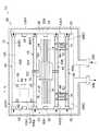
図1に示されるように、本実施形態に係る情報処理装置10は、基板12と、冷却ユニット20とを備える。基板12は、例えば、矩形状のプリント回路基板とされる。この基板12の表面は、複数の電子部品14が実装される実装面12Aとされる。この実装面12Aには、図示しないプリント配線が形成される。なお、基板12の裏面12B(図2参照)が、実装面とされても良い。<Information processing device>
As shown in FIG. 1, the
複数の電子部品14は、例えば、Central Processing Unit(CPU)、Large-Scale Integration(LSI)、又はメモリ等とされる。各電子部品14は、基板12の実装面12Aに形成されたプリント配線と電気的に接続される。なお、各電子部品14は、電力を消費することにより発熱する。 The plurality of
<冷却ユニット>
冷却ユニット20は、上流側主配管22、下流側主配管30、副配管40、及び複数の冷却モジュール50を有する。また、上流側主配管22は、冷媒が流れる上流側流路22Aを内部に有する。また、下流側主配管30は、冷媒が流れる下流側流路30Aを内部に有する。さらに、副配管40は、冷媒が流れる流路40Aを内部に有する。これらの上流側主配管22、下流側主配管30、及び副配管40は、冷媒を循環させる循環流路を形成する。<Cooling unit>
The
なお、上流側主配管22は、上流側流路部材の一例である。また、下流側主配管30は、下流側流路部材の一例である。さらに、副配管40は、流路部材の一例である。 The upstream
上流側主配管22及び下流側主配管30は、基板12の実装面12Aの外周部に沿って配置される。より具体的には、上流側主配管22は、基板12の実装面12Aの一端部12A1側の外周部に沿って配置される。一方、下流側主配管30は、基板12の実装面12Aの他端部12A2側の外周部に沿って配置される。つまり、下流側主配管30は、基板12の実装面12Aに実装された電子部品14(冷却器52)に対して、上流側主配管22と反対側に配置される。 The upstream
下流側主配管30の一端部30Eには、図示しない配管を介して冷媒冷却装置が接続される。これにより、下流側主配管30の一端部30Eから排出された冷媒が、冷媒冷却装置に供給される。冷媒冷却装置は、例えば、冷媒を冷却する冷凍機又は冷却塔とされる。なお、冷媒は、例えば、水等の液体とされる。また、図1に示される矢印は、冷媒の流れを表している。 A refrigerant cooling device is connected to one
冷媒冷却装置には、図示しない配管を介して上流側主配管22の一端部22Eが接続される。これにより、冷媒冷却装置によって冷却された冷媒が、上流側主配管22の一端部22Eに供給される。 One
上流側主配管22は、基板12の実装面12Aの一端部12A1に沿って配置される。この上流側主配管22には、複数の上流側継手部24が設けられる。 The upstream
複数の上流側継手部24は、ねじ式又はワンタッチ式等の着脱可能な流体継手とされる。各上流側継手部24は、上流側流路22Aに通じる。また、複数の上流側継手部24は、上流側主配管22の長手方向に間隔を空けて配列される。さらに、複数の上流側継手部24は、上流側主配管22に対して基板12の中央部側(下流側主配管30側)に配置される。なお、各上流側継手部24には、後述する副配管40の一端部40E1が着脱可能に連結される。 The plurality of upstream side
下流側主配管30は、基板12の実装面12Aの他端部12A2に沿って配置される。この下流側主配管30には、複数の下流側継手部32が設けられる。 The downstream
複数の下流側継手部32は、ねじ式又はワンタッチ式等の着脱可能な流体継手とされる。各下流側継手部32は、下流側流路30Aに通じる。また、複数の下流側継手部32は、下流側主配管30の長手方向に間隔を空けて配列される。さらに、複数の下流側継手部32は、下流側主配管30に対して基板12の中央部側(上流側主配管22側)に配置される。なお、各下流側継手部32には、後述する副配管40の他端部40E2が着脱可能に連結される。 The plurality of downstream side
<副配管>
複数の副配管40は、例えば、直線状の配管とされる。また、複数の副配管40は、基板12の実装面12A上に配置される。各副配管40の一端部40E1(上流側端部)は、流路40Aを上流側流路22Aに接続した状態で、複数の上流側継手部24の何れかに着脱可能に連結される。<Sub piping>
The plurality of
一方、副配管40の他端部(下流側端部)40E2は、流路40Aを下流側流路30Aに接続した状態で、複数の下流側継手部32の何れかに着脱可能に連結される。これにより、複数の副配管40によって、上流側主配管22と下流側主配管30とが繋がる。つまり、上流側主配管22と下流側主配管30との間には、複数の流路40Aが形成される。 On the other hand, the other end portion (downstream end portion) 40E2 of the
なお、本実施形態では、6つの上流側継手部24のうち、4つの上流側継手部24に副配管40がそれぞれ連結され、6つの下流側継手部32のうち、4つの下流側継手部32に副配管40がそれぞれ接続される。そして、上流側主配管22と下流側主配管30とが、4本の副配管40によって繋がれる。 In the present embodiment, the sub-pipes 40 are respectively connected to the four upstream
ここで、副配管40は、電子部品14に干渉しないように、隣り合う電子部品14の間に配置される。また、副配管40は、冷却器52,82,122が設置される電子部品14の両側に配置される。換言すると、隣り合う一対の副配管40の間に電子部品14がそれぞれ配置される。 Here, the
<冷却モジュール>
基板12の実装面12A上には、3種類の冷却モジュール50,80,120が設けられる。そのため、本実施形態では、冷却モジュール50について説明し、冷却モジュール80,120については、第2,第3実施形態において後述する。<Cooling module>
Three types of
図2に示されるように、冷却モジュール50は、冷却器52と、ベースプレート56と、複数の固定ポール58と、複数のナット62と、複数の弾性部材64とを有する。冷却器52は、熱伝導性を有し、電子部品14と副配管40とを熱交換させる熱交換器とされる。この冷却器52は、例えば、アルミニウム又は銅等の熱伝導率が高い金属材料によって板状に形成される。 As shown in FIG. 2, the
冷却器52の中央部は、吸熱部52Sとされる。この吸熱部52Sは、電子部品14上に当該電子部品14と熱交換可能に設置される。具体的には、電子部品14の上面は、平坦面14Aとされる。この電子部品14の平坦面14A上に、熱伝導部材54を介して冷却器52の吸熱部52Sが設置される。これにより、吸熱部52Sが電子部品14と熱交換可能になる。 The central portion of the cooler 52 is a
熱伝導部材54は、熱伝導性を有する。この熱伝導部材54は、例えば、熱伝導率が高い熱伝導ゴム、熱伝導グリス、又は熱伝導シート等のThermal Interface Material(TIM)が用いられる。これにより、電子部品14と冷却器52との間の熱伝導効率が高められる。 The
冷却器52は、電子部品14の両側に配置される一対の副配管40に亘って配置される。この冷却器52の一端部52E1は、一方の副配管40上に当該副配管40と熱交換可能に設置される。 The cooler 52 is arranged across the pair of
具体的には、副配管40の横断面形状は、矩形状を成している。また、副配管40の内部には、冷媒Wが流れる流路40Aが形成される。副配管40の上面は、平坦な接続面40Sとされる。この接続面40Sに、熱伝導部材54を介して冷却器52の一端部52E1の下面が面接触される。これにより、冷却器52の一端部52E1が、副配管40を介して流路40Aを流れる冷媒Wと熱交換可能になる。また、熱伝導部材54によって、冷却器52と副配管40との間の熱伝導効率が高められる。 Specifically, the cross-sectional shape of the
これと同様に、冷却器52の他端部52E2は、熱伝導部材54を介して、他方の副配管40の接続面40Sに接続される。これにより、冷却器52の他端部52E2と副配管40とが熱交換可能になる。 Similarly, the other end portion 52E2 of the cooler 52 is connected to the
ベースプレート56は、基板12の裏面12B側に配置される。また、ベースプレート56は、矩形の板状に形成される。このベースプレート56の各角部には、固定ポール58が立てられる。各固定ポール58は、基板12に形成された取付孔60に挿入されるとともに、冷却器52に形成された取付孔63に挿入される。 The
固定ポール58の先端部(上端部)には、雄ネジ部58Aが設けられる。この雄ネジ部58Aには、ナット62が取り付けられる。さらに、ナット62と冷却器52との間には、弾性部材64が配置される。そのため、固定ポール58に対してナット62が締め込まれると、ナット62と冷却器52との間で弾性部材64が圧縮された状態で保持される。これにより、冷却器52が、電子部品14の両側の副配管40の接続面40Sに着脱可能に接続される。 A
また、弾性部材64の付勢力(復元力)により、冷却器52の吸熱部52Sが熱伝導部材54を介して電子部品14の平坦面14Aに設置される。また、冷却器52の一端部52E1及び他端部52E2が、熱伝導部材54を介して一対の副配管40の接続面40Sにそれぞれ圧接される。これにより、冷却器52の吸熱部52Sと電子部品14と間、及び冷却器52の一端部52E1及び他端部52E2と一対の副配管40との間の熱伝導効率がそれぞれ高められる。 Further, the
次に、第1実施形態の作用について説明する。 Next, the operation of the first embodiment will be described.
図1に示されるように、上流側主配管22の一端部22Eには、図示しない冷媒冷却装置から、冷却された冷媒が供給される。この冷媒は、矢印で示されるように、上流側主配管22の上流側流路22Aを介して複数の副配管40の流路40Aへそれぞれ供給される。 As shown in FIG. 1, one
複数の副配管40に供給された冷媒は、下流側主配管30の下流側流路30Aに供給される。さらに、下流側流路30Aに供給された冷媒は、下流側主配管30の一端部30Eから冷媒冷却装置に供給され、当該冷媒冷却装置によって冷却される。冷媒冷却装置によって冷却された冷媒は、上流側主配管22の一端部22Eに再び供給される。 The refrigerant supplied to the plurality of
ここで、図2に矢印hで示されるように、電子部品14の熱は、冷却器52を介して副配管40に伝達される。さらに、副配管40に伝達された電子部品14の熱は、副配管40の流路40Aを流れる冷媒Wに放出される。これにより、電子部品14が冷却される。 Here, as indicated by an arrow h in FIG. 2, the heat of the
また、冷却器52は、電子部品14の両側に配置された一対の副配管40とそれぞれ熱交換する。つまり、冷却器52は、電子部品14の熱を一対の副配管40に放出する。これにより、本実施形態では、冷却器52が一方の副配管40のみと熱交換する場合と比較して、電子部品14の冷却効率が向上する。 Further, the cooler 52 exchanges heat with the pair of
ところで、例えば、図3に示される比較例のように、冷媒が流れる内部流路(図示省略)を有する冷却器70に配管72が溶接等で接合されている場合、電子部品14を交換する際に、基板12から冷却器70及び配管72を取り外すことなる。そのため、電子部品14の交換作業に手間がかかる可能性がある。 By the way, for example, when the
これに対して本実施形態では、複数のナット62によって、冷却器52が一対の副配管40に着脱可能に接続される。これにより、例えば、作業者が電子部品14を交換する場合に、基板12から一対の副配管40を取り外さずに、電子部品14上から冷却器52を取り外すことができる。したがって、本実施形態では、比較例に係る冷却器70と比べ、電子部品14の交換作業の手間が低減される。 On the other hand, in the present embodiment, the cooler 52 is detachably connected to the pair of
また、例えば、作業者が基板12の取付孔60の位置を変更することにより、副配管40に対する冷却器52の取り付け位置を容易に変更することができる。したがって、例えば、電子部品14のレイアウトの変更に応じて、冷却器52のレイアウトも容易に変更することができる。 Further, for example, an operator can easily change the attachment position of the cooler 52 with respect to the
さらに、上流側主配管22には、複数の上流側継手部24が設けられるとともに、下流側主配管30には、複数の下流側継手部32が設けられる。これにより、電子部品14のレイアウトに応じて、副配管40の配置も容易に変更することができる。さらに、上流側主配管22と下流側主配管30との間には、複数の副配管40が規則的に配管される。したがって、隣り合う副配管40の間の実装面12Aに、複数の電子部品14を高密度で実装することができる。 Further, the upstream
さらにまた、上流側主配管22及び下流側主配管30は、基板12の外周部に沿って配置される。これにより、基板12の中央部に、電子部品14の実装スペースを広く確保することができる。 Furthermore, the upstream
[変形例]
次に、第1実施形態の変形例について説明する。[Modification]
Next, a modified example of the first embodiment will be described.
図4に示される変形例では、副配管42の横断面形状が円形状(円筒状)を成している。また、冷却器52は、台座66を介して副配管42上に設置される。この台座66は、ブロック状に形成される。 In the modification shown in FIG. 4, the cross section of the
台座66の下面には、副配管42が嵌め込まれる凹部68が形成される。一方、台座66の上面は、平坦な接続面66Sとされる。この台座66の接続面66Sには、熱伝導部材54を介して冷却器52が面接触される。これにより、冷却器52と副配管42との間の熱伝導効率が向上するとともに、冷却器52の安定性が向上する。 A
また、図5に示される変位例では、冷却器52に複数のヒートパイプ44が設けられる。各ヒートパイプ44の内部には、図示しない作動液が封入される。これらのヒートパイプ44は、例えば、冷却器52の内部に埋設される。 Further, in the displacement example shown in FIG. 5, the cooler 52 is provided with a plurality of
各ヒートパイプ44は、蒸発部44A及び一対の凝縮部44Bを有する。蒸発部44Aは、ヒートパイプ44の長手方向の中間部に設けられ、吸熱部52Sに配置される。この蒸発部44Aは、電子部品14上に当該電子部品14と熱交換可能に配置される。一方、一対の凝縮部44Bは、ヒートパイプ44の長手方向の両端部に設けられる。この一対の凝縮部44Bは、一対の副配管40上に当該副配管40と熱交換可能に配置される。 Each
ここで、電子部品14の熱によってヒートパイプ44の蒸発部44A中の作動液が蒸発すると、電子部品14から蒸発潜熱が奪われる。これにより、電子部品14が冷却される。また、蒸発部44Aにおいて蒸発した気相状態の作動液は、凝縮部44Bへ移動し、副配管40によって冷却されて凝縮される。 Here, when the working fluid in the
蒸発部44Aにおいて凝縮された液相状態の作動液は、例えば、図示しないウィックを介して蒸発部44Aへ供給され、蒸発部44Aにおいて再び蒸発される。この作動液を介して、電子部品14と副配管40との間で熱が移動する。つまり、電子部品14と副配管40との熱交換が促進される。したがって、電子部品14と副配管40とが熱交換効率が向上するため、電子部品14の冷却効率が向上する。 The liquid-phase working fluid condensed in the
[第2実施形態]
次に、第2実施形態について説明する。なお、第2実施形態において、第1実施形態と同じ構成の部材等には、同符号を付して説明を適宜省略する。[Second Embodiment]
Next, a second embodiment will be described. In addition, in the second embodiment, members and the like having the same configurations as those of the first embodiment are denoted by the same reference numerals, and description thereof will be appropriately omitted.
図6に示されるように、第2実施形態に係る冷却モジュール80は、冷却器82を有する。冷却器82は、一対の副配管40のうち、一方の副配管40から供給された冷媒と電子部品14とを熱交換させることにより、電子部品14を冷却する。 As shown in FIG. 6, the
具体的には、冷却器82は、一対の副配管40に亘って配置される。この冷却器82の中央部は、電子部品14と熱交換する吸熱部82Sとされる。吸熱部82Sは、電子部品14上に熱伝導部材54(図7参照)を介して設置される。 Specifically, the cooler 82 is arranged across the pair of
冷却器82は、冷媒が流れる内部流路84を有する。この内部流路84の一端部84E1には、一方の副配管40の流路40Aから冷媒が供給される。また、内部流路84の中間部(一部)は、冷却器82の吸熱部82Sに配置される。これにより、吸熱部82Sにおいて、内部流路84を流れる冷媒と電子部品14とが熱交換する。この結果、電子部品14が冷却される。また、電子部品14と熱交換した冷媒は、内部流路84の他端部84E2から一方の副配管40に排出される。 The cooler 82 has an
なお、冷却器82には、内部流路84を仕切るフィン85が適宜形成される。また、矢印Fは、冷媒の流れを示している。 In addition,
<冷却器の接続構造>
次に、一対の副配管40に対する冷却器82の接続構造及び取付構造について説明する。先ず、一方の副配管40に対する冷却器82の接続構造について説明する。一方の副配管40は、複数の接続孔46を有する。複数の接続孔46(図7参照)は、副配管40の長手方向に間隔を空けて配置される。各接続孔46は、副配管40内の流路40Aに通じる。<Cooler connection structure>
Next, a connection structure and a mounting structure of the cooler 82 with respect to the pair of
図6に示されるように、冷却器82は、一方の副配管40に着脱可能に接続される上流側接続部86及び下流側接続部94を有する。図7に示されるように、上流側接続部86の内部には、内部流路84の一端部84E1が形成される。また、上流側接続部86の下面には、内部流路84に通じる接続孔88が形成される。 As shown in FIG. 6, the cooler 82 has an upstream-
上流側接続部86は、副配管40の上面にシール材(Oリング)90を介して設置される。この際、副配管40の接続孔46と上流側接続部86の接続孔88とが接続される。なお、シール材90は、接続孔46,88を囲むリング状に形成される。このシール材90によって、接続孔46,88からの冷媒Wの漏れが抑制される。 The upstream
上流側接続部86の上面には、接続孔88と対向する取付孔92が形成される。この取付孔92には、取付部材100の軸部104が挿入される。取付部材100は、例えば、ネジ部材とされる。この取付部材100は、蓋部102及び軸部104を有する。 An
蓋部102は、円盤状に形成される。また、蓋部102の表面には、例えば、ドライバー等の工具が係合される十字状の溝が形成される。この蓋部102は、シール材90を介して上流側接続部86の上面に載置される。この蓋部102によって、取付孔92が閉じられる。また、取付孔92を囲むリング状のシール材90によって、取付孔92からの冷媒Wの漏れが抑制される。 The
軸部104は、蓋部102の下面から延出し、取付孔92及び接続孔46,88に挿入される。この軸部104の先端部には、雄ネジ部104Aが設けられる。一方、副配管40の底部には、筒状のボス部48が形成される。 The
ボス部48の内周面には、雌ネジ部が形成される。このボス部48に軸部104の雄ネジ部104Aが締め込まれる。これにより、内部流路84の一端部84E1と副配管40の流路40Aとが接続された状態で、上流側接続部86が副配管40に着脱可能に取り付けられる。この状態で、一方の副配管40の流路40Aから内部流路84の一端部84E1に冷媒Wが供給される。 A female screw portion is formed on the inner peripheral surface of the
図7に示されるように、下流側接続部94には、内部流路84の他端部84E2が形成される。また、下流側接続部94は、上流側接続部86と同様の構成とされる。この下流側接続部94は、内部流路84の他端部84E2と副配管40の流路40Aとを接続した状態で、取付部材100によって一方の副配管40に着脱可能に取り付けられる。これにより、内部流路84の他端部84E2から、一方の副配管40の流路40Aに冷媒が排出される。 As shown in FIG. 7, the
次に、他方の副配管40に対する冷却器82の取付構造について説明する。冷却器82は、他方の副配管40に着脱可能に取り付けられる2つ取付部96を有する。なお、他方の副配管40にも、複数の接続孔46が形成される。 Next, a mounting structure of the cooler 82 to the
2つの取付部96は、前述した上流側接続部86及び下流側接続部94と同様の構成とされており、取付部材100によって他方の副配管40に着脱可能に取り付けられる。ただし、2つの取付部96の内部には、内部流路84が形成されない。したがって、一方の副配管40から内部流路84の一端部84E1に供給された冷媒は、矢印Fで示されるように、他方の副配管40には排出されず、内部流路84の他端部84E2から一方の副配管40に排出される。 The two
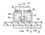
なお、副配管40の複数の接続孔46のうち、取付部材100が挿入されない接続孔46は、蓋部材110によって閉塞される。具体的には、図8Aに示されるように、蓋部材110は、蓋部112及び軸部114を有する。 Of the plurality of connection holes 46 of the
蓋部112は、円盤状に形成される。また、蓋部112の表面には、例えば、ドライバー等の工具が係合される十字状の溝が形成される。この蓋部112は、副配管40の上面に、シール材90を介して載置される。この蓋部112によって、接続孔46が閉じられる。また、接続孔46を囲むリング状のシール材90によって、接続孔46からの冷媒Wの漏れが抑制される。 The
軸部114は、蓋部112の下面から延出し、接続孔46に挿入される。この軸部114の先端部には、雄ネジ部114Aが設けられる。一方、副配管40の底部には、前述したボス部48が形成される。ボス部48の内周面には、雌ネジ部が形成される。このボス部48に軸部114の雄ネジ部114Aが締め込まれる。これにより、副配管40に蓋部材110が着脱可能に取り付けられる。 The
<流路の閉塞構造>
図6に示されるように、本実施形態の副配管40には、上流側接続部86と下流側接続部94との間において、流路40Aを閉塞する閉塞部108が設けられる。具体的には、図8Bに示されるように、閉塞部108に形成された接続孔46は、前述した蓋部材110によって閉じられる。<Flow path blockage structure>
As shown in FIG. 6, the
また、閉塞部108では、接続孔46から流路40Aに吸水ポリマー等の閉塞材116が充填される。この閉塞材116によって、流路40Aが閉塞される。これにより、図6に矢印Fで示されるように、一方の副配管40の流路40Aから上流側接続部86を介して内部流路84の一端部84E1に冷媒が流れ易くなる。したがって、電子部品14の冷却効率が向上する。 Further, in the
次に、第2実施形態の作用について説明する。 Next, the operation of the second embodiment will be described.
図6に示されるように、冷却モジュール80は、一対の副配管40に亘って配置される冷却器82を有する。冷却器82は、内部流路84を有する。この内部流路84の一端部84E1は、上流側接続部86において一方の副配管40の流路40Aと接続される。これにより、一方の副配管40から内部流路84の一端部84E1に冷媒が供給される。 As shown in FIG. 6, the
また、内部流路84の他端部84E2は、下流側接続部94において一方の副配管40の流路40Aと接続される。これにより、内部流路84内に冷媒が、内部流路84の他端部84E2から一方の副配管40の流路40Aに排出される。 Further, the other end portion 84E2 of the
ここで、内部流路84の一部は、冷却器82の吸熱部82Sに配置される。これにより、吸熱部82Sにおいて、内部流路84を流れる冷媒と、電子部品14とが熱交換する。これにより、電子部品14が冷却される。 Here, a part of the
このように本実施形態では、冷媒と電子部品14とが熱交換することにより、電子部品14が冷却される。したがって、電子部品14の冷却効率が向上する。 As described above, in the present embodiment, the
また、副配管40には、閉塞部108が設けられる。閉塞部108は、上流側接続部86と下流側接続部94との間に設けられる。この閉塞部108では、一方の副配管40の流路40Aが閉塞材116によって閉塞される。これにより、図6に矢印Fで示されるように、一方の副配管40の流路40Aから、上流側接続部86を介して内部流路84の一端部84E1に冷媒が供給され易くなる。したがって、電子部品14の冷却効率がさらに向上する。 Further, the sub-pipe 40 is provided with a closing
また、冷却器82は、取付部材100によって、一対の副配管40に対して着脱可能に接続される。これにより、上記第1実施形態と同様に、電子部品14の交換作業の手間が低減される。 Further, the cooler 82 is detachably connected to the pair of
[変形例]
次に、第2実施形態の変形例について説明する。[Modification]
Next, a modified example of the second embodiment will be described.
図9及び図10に示される変形例のように、冷却器82の内部流路84の形状は、適宜変更可能である。また、図11に示される変形例では、一方の副配管40に上流側接続部86が着脱可能に接続されるとともに、他方の副配管40に下流側接続部94が着脱可能に接続される。この場合、内部流路84には、一方の副配管40の流路40Aから上流側接続部86を介して内部流路84の一端部84E1に冷媒が供給される。また、内部流路84内の冷媒は、下流側接続部94を介して内部流路84の他端部84E2から他方の副配管40の流路40Aに排出される。 As in the modified example shown in FIGS. 9 and 10, the shape of the
また、一方の副配管40には、下流側閉塞部118が設けられる。下流側閉塞部118は、内部流路84の一端部84E1が接続される接続孔46の下流側において、一方の副配管40の流路40Aを閉塞する。これにより、一方の副配管40の流路40Aから、内部流路84の一端部84E1へ冷媒が流れ易くなる。 Further, the downstream
また、他方の副配管40には、上流側閉塞部119が設けられる。上流側閉塞部119は、内部流路84の他端部84E2が接続される接続孔46の上流側において、他方の副配管40の流路40Aを閉塞する。これにより、他方の副配管40の流路40Aから、内部流路84の他端部84E2へ冷媒が逆流することが抑制される。なお、下流側閉塞部118及び上流側閉塞部119は、前述した閉塞部108(図8B参照)と同様の構成とされる。 Further, the upstream
[第3実施形態]
次に、第3実施形態について説明する。なお、第3実施形態において、第1,第2実施形態と同じ構成の部材等には、同符号を付して説明を適宜省略する。[Third Embodiment]
Next, a third embodiment will be described. In addition, in the third embodiment, members and the like having the same configurations as those of the first and second embodiments are denoted by the same reference numerals, and description thereof will be appropriately omitted.
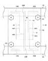
図12に示されるように、第3実施形態に係る冷却モジュール120は、冷却器122を有する。冷却器122は、例えば、電子部品14へ流れる風Vを冷却することにより、電子部品14を冷却するラジエータとされる。 As shown in FIG. 12, the
具体的には、冷却器122は、内部流路122Aを有する。また、冷却器122は、上流側接続部86及び下流側接続部94を有する。上流側接続部86は、一方の副配管40に着脱可能に接続される。これにより、一方の副配管40の流路40Aから上流側接続部86を介して内部流路122Aの一端部に冷媒が供給される。 Specifically, the cooler 122 has an
これに対して下流側接続部94は、他方の副配管40に着脱可能に接続される。これにより、内部流路122A内の冷媒が、内部流路122Aの他端部から下流側接続部94を介して他方の副配管40の流路40Aへ排出される。なお、一対の副配管40には、流路40Aを閉塞する閉塞部が設けられても良い。 On the other hand, the downstream
ここで、第3実施形態に係る情報処理装置10には、電子部品14へ風を送る送風機(ファン)124が設けられる。また、基板12の実装面12Aには、電子部品14に対し、風Vの上流側に配置される上流側電子部品16が実装される。この上流側電子部品16と電子部品(下流側電子部品)14との間に、冷却器122が配置される。なお、電子部品14及び上流側電子部品16は、例えば、メモリとされる。 Here, the
次に、第3実施形態の作用について説明する。 Next, the operation of the third embodiment will be described.
図12に示されるように、送風機124が作動すると、上流側電子部品16へ流れる風Vが生成される。この風Vによって、上流側電子部品16が冷却される。次に、上流側電子部品16を通過した風Vは、冷却器122を通過する。この際、冷却器122の内部流路122Aを流れる冷媒によって風Vが冷却される。次に、冷却器122を通過した風Vは、電子部品14を通過する。この風Vによって、電子部品14が冷却される。 As shown in FIG. 12, when the
ここで、図12には、冷却器122がある場合の風Vの温度がグラフG1で示される。また、図12には、比較例として、冷却器122がない場合の風Vの温度がグラフG2で示される。なお、グラフG1,G2の横軸は、下流側継手部32からの距離である。 Here, in FIG. 12, the temperature of the wind V when the cooler 122 is provided is shown by a graph G1. Further, in FIG. 12, as a comparative example, the temperature of the wind V when the cooler 122 is not provided is shown by a graph G2. The horizontal axes of the graphs G1 and G2 are distances from the downstream
グラフG2から分かるように、冷却器122がない場合には、風Vは、上流側電子部品16の通過に伴って加熱され、温度が上昇する。その後、風Vは、温度が上昇したまま電子部品14を通過する。したがって、電子部品14の冷却効率が低下する。 As can be seen from the graph G2, when the cooler 122 is not provided, the wind V is heated as the upstream
これに対して本実施形態では、グラフG1から分かるように、上流側電子部品16を通過した風Vは、冷却器122によって冷却され、温度が低下する。その後、風Vは、電子部品14を通過する。したがって、本実施形態では、電子部品14の冷却効率が向上する。 On the other hand, in the present embodiment, as can be seen from the graph G1, the wind V that has passed through the upstream
また、本実施形態では、グラフG1から分かるように、上流側電子部品16を通過する前の風Vの温度と、電子部品14を通過した風Vの温度とを略同じにすることができる。つまり、情報処理装置10に流入する風Vの温度と、情報処理装置10から流出する風Vの温度とを略同じにすることができる。これにより、例えば、情報処理装置10が設置されるサーバルームの温度上昇が抑制される。この結果、サーバルームの空調負荷が軽減される。 Further, in this embodiment, as can be seen from the graph G1, the temperature of the wind V before passing through the upstream
ところで、冷却器122が電子部品14に隣接して配置されると、作業者が電子部品14を交換する際に、電子部品14又は作業者の手が冷却器122に干渉する可能性がある。この場合、電子部品14の交換作業に手間がかかる可能性がある。 By the way, if the cooler 122 is arranged adjacent to the
これに対して本実施形態では、一対の副配管40に冷却器122が着脱可能に接続される。これにより、作業者が電子部品14を交換する場合に、基板12から副配管40を取り外さずに、基板12から冷却器122を取り外すことができる。したがって、電子部品14の交換作業の手間が低減される。 On the other hand, in the present embodiment, the cooler 122 is detachably connected to the pair of
なお、本実施形態では、冷却器122の上流側に上流側電子部品16が配置されるが、上流側電子部品16は省略可能である。 In this embodiment, the upstream
次に、上記第1〜第3実施形態の変形例について説明する。なお、以下では、第1実施形態を例に各種の変形例について説明するが、これらの変形例は、第2,第3実施形態にも適宜適用可能である。 Next, modified examples of the first to third embodiments will be described. In the following, various modifications will be described with the first embodiment as an example, but these modifications are also applicable to the second and third embodiments as appropriate.
また、上記第1実施形態では、電子部品14の両側に副配管40が配置されるが、電子部品14の片側にのみ副配管40が配置されても良い。例えば、冷却器52の他端部52E2側に副配管40が配置されない場合は、当該他端部52E2は、図示しないスペーサ等を介して基板12に取り付けられる。 Further, in the first embodiment, the sub-pipe 40 is arranged on both sides of the
また、上記第1実施形態において、上流側主配管22、下流側主配管30、及び副配管40の配置、数、及び構造は、適宜変更可能である。 Moreover, in the said 1st Embodiment, the arrangement|positioning, the number, and structure of the upstream
また、上記第1実施形態に係る冷却ユニット20は、上流側主配管22、下流側主配管30、副配管40を備えるが、上流側主配管22及び下流側主配管30は、省略可能である。なお、上流側主配管22及び下流側主配管30が省略された場合は、例えば、流路部材に、配管等を介して冷媒冷却装置が接続される。 Further, the cooling
以上、本願が開示する技術の一実施形態について説明したが、本願が開示する技術は上記の実施形態に限定されるものでない。また、上記実施形態及び各種の変形例を適宜組み合わせて用いても良いし、本願が開示する技術の要旨を逸脱しない範囲において、種々なる態様で実施し得ることは勿論である。 Although one embodiment of the technology disclosed by the present application has been described above, the technology disclosed by the present application is not limited to the above embodiment. Further, the above embodiment and various modifications may be appropriately combined and used, and it goes without saying that the invention can be implemented in various modes without departing from the gist of the technique disclosed in the present application.
なお、以上の実施形態に関し、さらに以下の付記を開示する。 The following supplementary notes will be disclosed regarding the above-described embodiment.
(付記1)
電子部品が実装された実装面を有する基板と、
冷媒が流れる流路を有し、前記実装面上に配置される流路部材と、
前記流路部材に着脱可能に接続され、前記電子部品を冷却する冷却器と、
を備える情報処理装置。
(付記2)
冷媒が流れる上流側流路と、前記上流側流路に通じる複数の上流側継手部と、を有する上流側流路部材を備え、
前記流路部材は、前記流路を前記上流側流路に接続した状態で、複数の前記上流側継手部の何れかに連結される、
付記1に記載の情報処理装置。
(付記3)
冷媒が流れる下流側流路と、前記下流側流路に通じる複数の下流側継手部と、を有し、前記冷却器に対して前記上流側流路と反対側に配置される下流側流路部材を備え、
前記流路部材は、前記流路を前記下流側流路に接続した状態で、複数の前記下流側継手部の何れかに連結される、
付記2に記載の情報処理装置。
(付記4)
前記上流側流路部材は、前記実装面の一端部に沿って配置される、
付記3に記載の情報処理装置。
(付記5)
前記下流側流路部材は、前記実装面の他端部に沿って配置される、
付記4に記載の情報処理装置。
(付記6)
一対の前記流路部材の間に前記電子部品が配置され、
前記冷却器は、一対の前記流路部材に亘って配置される、
付記1〜付記5の何れか1つに記載の情報処理装置。
(付記7)
前記冷却器は、前記電子部品上に配置され、該電子部品と熱交換する吸熱部を有する、
付記1〜付記5の何れか1つに記載の情報処理装置。
(付記8)
前記冷却器は、冷媒が流れるとともに一部が前記吸熱部に配置され、前記流路に着脱可能に接続される内部流路を有する、
付記7に記載の情報処理装置。
(付記9)
前記流路部材は、前記流路に通じる複数の接続孔を有し、
前記内部流路の一端部は、複数の前記接続孔の何れかに接続される、
付記8に記載の情報処理装置。
(付記10)
前記内部流路の他端部は、複数の前記接続孔のうち、前記内部流路の前記一端部が接続される前記接続孔とは異なる前記接続孔に接続される、
付記9に記載の情報処理装置。
(付記11)
前記流路部材には、前記内部流路の前記一端部が接続される前記接続孔と前記内部流路の前記他端部が接続される前記接続孔との間において、前記流路を閉塞する閉塞部が設けられる、
付記10に記載の情報処理装置。
(付記12)
一対の前記流路部材の間に前記電子部品が配置され、
前記内部流路の前記一端部は、一方の前記流路部材の複数の前記接続孔の何れかに接続され、
前記内部流路の前記他端部は、他方の前記流路部材の複数の前記接続孔の何れかに接続される、
付記10又は付記11に記載の情報処理装置。
(付記13)
一方の前記流路部材には、前記内部流路の前記一端部が接続される前記接続孔の下流側において、前記流路を閉塞する下流側閉塞部が設けられる、
付記12に記載の情報処理装置。
(付記14)
他方の前記流路部材には、前記内部流路の前記他端部が接続される前記接続孔の上流側において、前記流路を閉塞する上流側閉塞部が設けられる、
付記12又は付記13に記載の情報処理装置。
(付記15)
前記冷却器は、熱伝導性を有し、前記流路部材に接続された状態で該流路部材と熱交換する、
付記1〜付記7の何れか1つに記載の情報処理装置。
(付記16)
前記流路部材は、前記冷却器が面接触される接続面を有する、
付記15に記載の情報処理装置。
(付記17)
前記冷却器は、前記電子部品と前記流路部材とを熱交換させるヒートパイプを有する、
付記15又は付記16に記載の情報処理装置。
(付記18)
前記電子部品へ流れる風を生成する送風機を備え、
前記冷却器は、前記送風機から前記電子部品へ流れる風を冷却する、
付記1〜付記6の何れか1つに記載の情報処理装置。
(付記19)
前記電子部品に対し、前記送風機が生成する風の上流側に配置される上流側電子部品を有し、
前記冷却器は、前記電子部品と前記上流側電子部品との間に配置される、
付記18に記載の情報処理装置。
(付記20)
冷媒が流れる流路を有し、電子部品が実装された基板の実装面上に配置される流路部材と、
前記流路部材に着脱可能に接続され、前記電子部品を冷却する冷却器と、
を備える冷却ユニット。(Appendix 1)
A substrate having a mounting surface on which electronic components are mounted,
Having a flow path through which the refrigerant flows, a flow path member arranged on the mounting surface,
A cooler that is detachably connected to the flow path member and cools the electronic component,
An information processing apparatus including.
(Appendix 2)
An upstream side flow path member having an upstream side flow path through which the refrigerant flows, and a plurality of upstream side joint parts communicating with the upstream side flow path,
The flow path member is connected to any one of the plurality of upstream side joint parts in a state where the flow path is connected to the upstream side flow path.
The information processing device according to
(Appendix 3)
A downstream side flow path having a downstream side flow path through which a refrigerant flows and a plurality of downstream side joint parts communicating with the downstream side flow path, the downstream side flow path being arranged on the opposite side to the upstream side flow path with respect to the cooler. Equipped with members,
The flow path member is connected to any of the plurality of downstream side joint parts in a state where the flow path is connected to the downstream side flow path,
The information processing device according to
(Appendix 4)
The upstream channel member is arranged along one end of the mounting surface,
The information processing device according to
(Appendix 5)
The downstream channel member is disposed along the other end of the mounting surface,
The information processing device according to attachment 4.
(Appendix 6)
The electronic component is arranged between the pair of flow path members,
The cooler is arranged across the pair of flow path members,
The information processing device according to any one of
(Appendix 7)
The cooler is disposed on the electronic component and has a heat absorbing portion that exchanges heat with the electronic component,
The information processing device according to any one of
(Appendix 8)
The cooler has an internal flow path in which the refrigerant flows and a part of the cooler is disposed in the heat absorption section, and the flow path is detachably connected to the flow path.
The information processing device according to
(Appendix 9)
The flow path member has a plurality of connection holes communicating with the flow path,
One end of the internal flow path is connected to any of the plurality of connection holes,
The information processing device according to attachment 8.
(Appendix 10)
The other end of the internal flow path is connected to the connection hole that is different from the connection hole to which the one end of the internal flow path is connected among the plurality of connection holes.
The information processing device according to attachment 9.
(Appendix 11)
The flow path member closes the flow path between the connection hole to which the one end of the internal flow path is connected and the connection hole to which the other end of the internal flow path is connected. A closure is provided,
The information processing device according to
(Appendix 12)
The electronic component is arranged between the pair of flow path members,
The one end of the internal flow path is connected to any of the plurality of connection holes of the one flow path member,
The other end of the internal flow path is connected to any of the plurality of connection holes of the other flow path member,
The information processing device according to
(Appendix 13)
One of the flow path members is provided with a downstream blocking portion that closes the flow path on the downstream side of the connection hole to which the one end of the internal flow path is connected,
The information processing device according to
(Appendix 14)
On the other side of the flow path member, an upstream side closing portion that closes the flow path is provided on the upstream side of the connection hole to which the other end of the internal flow path is connected.
The information processing apparatus according to
(Appendix 15)
The cooler has thermal conductivity and exchanges heat with the flow path member in a state of being connected to the flow path member,
The information processing apparatus according to any one of
(Appendix 16)
The flow path member has a connection surface with which the cooler is in surface contact,
The information processing device according to attachment 15.
(Appendix 17)
The cooler has a heat pipe for heat exchange between the electronic component and the flow path member,
The information processing apparatus according to
(Appendix 18)
A blower for generating wind flowing to the electronic component,
The cooler cools the air flowing from the blower to the electronic component,
The information processing apparatus according to any one of
(Appendix 19)
With respect to the electronic component, has an upstream electronic component arranged on the upstream side of the wind generated by the blower,
The cooler is disposed between the electronic component and the upstream electronic component,
The information processing device according to
(Appendix 20)
A flow path member having a flow path through which the coolant flows is disposed on the mounting surface of the board on which the electronic component is mounted,
A cooler that is detachably connected to the flow path member and cools the electronic component,
A cooling unit equipped with.
10 情報処理装置
12 基板
12A 実装面
12A1 一端部
12A2 他端部
14 電子部品
16 上流側電子部品
20 冷却ユニット
22 上流側主配管(上流側流路部材の一例)
22A 上流側流路
24 上流側継手部
30 下流側主配管(下流側流路部材の一例)
30A 下流側流路
32 下流側継手部
40 副配管(流路部材の一例)
40A 流路
40S 接続面
42 副配管
44 ヒートパイプ
46 接続孔
52S 吸熱部
52 冷却器
82 冷却器
82S 吸熱部
84 内部流路
84E1 一端部(内部流路の一端部の一例)
84E2 他端部(内部流路の他端部の一例)
86 上流側接続部
94 下流側接続部
108 閉塞部
118 下流側閉塞部
119 上流側閉塞部
122 冷却器
122A 内部流路
124 送風機
V 風
W 冷媒10
22A
30A Downstream
84E2 other end (an example of the other end of the internal flow path)
86 upstream connecting
Claims (7)
Translated fromJapanese冷媒が流れる流路を有し、前記実装面上に配置される流路部材と、
前記流路部材に着脱可能に接続され、前記電子部品を冷却する冷却器と、
冷媒が流れる上流側流路と、前記上流側流路に通じる複数の上流側継手部と、を有する上流側流路部材と、
冷媒が流れる下流側流路と、前記下流側流路に通じる複数の下流側継手部と、を有し、前記冷却器に対して前記上流側流路と反対側に配置される下流側流路部材と、
を備え、
前記流路部材は、前記流路を前記上流側流路に接続した状態で、複数の前記上流側継手部の何れかに連結されるとともに、前記流路を前記下流側流路に接続した状態で、複数の前記下流側継手部の何れかに連結される、
情報処理装置。A substrate having a mounting surface on which electronic components are mounted,
Having a flow path through which the refrigerant flows, a flow path member arranged on the mounting surface,
A cooler that is detachably connected to the flow path member and cools the electronic component,
An upstream flow passage member having an upstream flow passage through which the refrigerant flows, and a plurality of upstream joint portions communicating with the upstream flow passage,
A downstream-side flow path having a downstream-side flow path through which a refrigerant flows and a plurality of downstream-side joint portions communicating with the downstream-side flow path, the downstream-side flow path being arranged on the opposite side of the upstream-side flow path with respect to the cooler. Members,
Equipped with
The flow path member is connected to any one of the plurality of upstream side joint parts in a state where the flow path is connected to the upstream side flow path, and the flow path is connected to the downstream side flow path. In, is connected to any of the plurality of downstream side joint portion,
Information processing equipment.
前記冷却器は、一対の前記流路部材に亘って配置される、
請求項1に記載の情報処理装置。The electronic component is arranged between the pair of flow path members,
The cooler is arranged across the pair of flow path members,
The information processing apparatus accordingto claim1 .
請求項1又は請求項2に記載の情報処理装置。The cooler is disposed on the electronic component and has a heat absorbing portion that exchanges heat with the electronic component,
The information processing apparatus according toclaim 1or 2 .
請求項3に記載の情報処理装置。The cooler has an internal flow path in which the refrigerant flows and a part of the cooler is disposed in the heat absorption section, and the flow path is detachably connected to the flow path.
The information processing apparatus according toclaim 3 .
請求項1〜請求項4の何れか1項に記載の情報処理装置。The cooler has thermal conductivity and exchanges heat with the flow path member in a state of being connected to the flow path member,
The information processing apparatus according to any one ofclaims 1 to 4 .
前記冷却器は、前記送風機から前記電子部品へ流れる風を冷却する、
請求項1又は請求項2に記載の情報処理装置。A blower for generating wind flowing to the electronic component,
The cooler cools the air flowing from the blower to the electronic component,
The information processing apparatus according toclaim 1or 2 .
前記流路部材に着脱可能に接続され、前記電子部品を冷却する冷却器と、
冷媒が流れる上流側流路と、前記上流側流路に通じる複数の上流側継手部と、を有する上流側流路部材と、
冷媒が流れる下流側流路と、前記下流側流路に通じる複数の下流側継手部と、を有し、前記冷却器に対して前記上流側流路と反対側に配置される下流側流路部材と、
を備え、
前記流路部材は、前記流路を前記上流側流路に接続した状態で、複数の前記上流側継手部の何れかに連結されるとともに、前記流路を前記下流側流路に接続した状態で、複数の前記下流側継手部の何れかに連結される、
冷却ユニット。A flow path member having a flow path through which the coolant flows is disposed on the mounting surface of the board on which the electronic component is mounted,
A cooler that is detachably connected to the flow path member and cools the electronic component,
An upstream flow passage member having an upstream flow passage through which the refrigerant flows, and a plurality of upstream joint portions communicating with the upstream flow passage,
A downstream-side flow path that has a downstream-side flow path through which a refrigerant flows and a plurality of downstream-side joint portions that communicate with the downstream-side flow path, and is arranged on the opposite side of the upstream-side flow path with respect to the cooler. Members,
Equipped with
The flow path member is connected to any one of the plurality of upstream side joint portions in a state where the flow path is connected to the upstream side flow path, and the flow path is connected to the downstream side flow path. In, is connected to any of the plurality of downstream side joint portion,
Cooling unit.
Priority Applications (2)
| Application Number | Priority Date | Filing Date | Title |
|---|---|---|---|
| JP2016130415AJP6717080B2 (en) | 2016-06-30 | 2016-06-30 | Information processing device and cooling unit |
| US15/607,851US10014239B2 (en) | 2016-06-30 | 2017-05-30 | Information processing device and cooling unit |
Applications Claiming Priority (1)
| Application Number | Priority Date | Filing Date | Title |
|---|---|---|---|
| JP2016130415AJP6717080B2 (en) | 2016-06-30 | 2016-06-30 | Information processing device and cooling unit |
Publications (2)
| Publication Number | Publication Date |
|---|---|
| JP2018006526A JP2018006526A (en) | 2018-01-11 |
| JP6717080B2true JP6717080B2 (en) | 2020-07-01 |
Family
ID=60807885
Family Applications (1)
| Application Number | Title | Priority Date | Filing Date |
|---|---|---|---|
| JP2016130415AExpired - Fee RelatedJP6717080B2 (en) | 2016-06-30 | 2016-06-30 | Information processing device and cooling unit |
Country Status (2)
| Country | Link |
|---|---|
| US (1) | US10014239B2 (en) |
| JP (1) | JP6717080B2 (en) |
Families Citing this family (14)
| Publication number | Priority date | Publication date | Assignee | Title |
|---|---|---|---|---|
| US10681846B2 (en)* | 2018-04-19 | 2020-06-09 | Google Llc | Cooling electronic devices in a data center |
| US10645847B2 (en) | 2018-04-20 | 2020-05-05 | Google Llc | Cooling electronic devices in a data center |
| US20190357386A1 (en)* | 2018-05-16 | 2019-11-21 | GM Global Technology Operations LLC | Vascular polymeric assembly |
| US10798847B2 (en)* | 2018-06-27 | 2020-10-06 | Intel Corporation | Modular heat transfer system |
| US10966352B2 (en) | 2018-09-24 | 2021-03-30 | Google Llc | Cooling electronic devices in a data center |
| US10548239B1 (en)* | 2018-10-23 | 2020-01-28 | Google Llc | Cooling electronic devices in a data center |
| DE102019200096A1 (en)* | 2019-01-07 | 2020-07-09 | Zf Friedrichshafen Ag | Electronic device and method for assembling an electronic device |
| US10548240B1 (en) | 2019-01-11 | 2020-01-28 | Google Llc | Cooling electronic devices in a data center |
| US10966354B1 (en)* | 2020-03-23 | 2021-03-30 | Baidu Usa Llc | Liquid cooling module |
| US11406041B1 (en)* | 2020-03-26 | 2022-08-02 | Amazon Technologies, Inc. | Modular liquid cooling assembly |
| JP7460483B2 (en)* | 2020-08-27 | 2024-04-02 | 本田技研工業株式会社 | Heating element cooling mechanism |
| US11700709B2 (en)* | 2021-07-23 | 2023-07-11 | Baidu Usa Llc | Redundant module and systems for high density servers |
| US11925001B2 (en)* | 2022-03-22 | 2024-03-05 | Baidu Usa Llc | High power density chips based two-phase loop recirculation |
| EP4345578A1 (en)* | 2022-09-28 | 2024-04-03 | Bull Sas | Assembled cold plate for computing blade |
Family Cites Families (29)
| Publication number | Priority date | Publication date | Assignee | Title |
|---|---|---|---|---|
| JPH02197195A (en)* | 1989-01-26 | 1990-08-03 | Nec Corp | Multistage mounting cooling structure of electronic equipment |
| US5509468A (en)* | 1993-12-23 | 1996-04-23 | Storage Technology Corporation | Assembly for dissipating thermal energy contained in an electrical circuit element and associated method therefor |
| JPH07297505A (en) | 1994-04-20 | 1995-11-10 | Hitachi Ltd | Printed wiring board |
| JPH08172285A (en)* | 1994-12-16 | 1996-07-02 | Asia Electron Inc | Cooling plate and cooling device |
| US5740018A (en)* | 1996-02-29 | 1998-04-14 | The United States Of America As Represented By The Secretary Of The Navy | Environmentally controlled circuit pack and cabinet |
| JPH11163565A (en)* | 1997-11-27 | 1999-06-18 | Ando Electric Co Ltd | Cooling structure for printed board |
| JP3431009B2 (en)* | 2000-04-11 | 2003-07-28 | 日本電気株式会社 | Electronic circuit board cooling device |
| JP2005191473A (en)* | 2003-12-26 | 2005-07-14 | Honda Motor Co Ltd | Circuit board cooling device |
| US7187549B2 (en)* | 2004-06-30 | 2007-03-06 | Teradyne, Inc. | Heat exchange apparatus with parallel flow |
| US7380409B2 (en)* | 2004-09-30 | 2008-06-03 | International Business Machines Corporation | Isolation valve and coolant connect/disconnect assemblies and methods of fabrication for interfacing a liquid cooled electronics subsystem and an electronics housing |
| EP1810558B1 (en)* | 2004-11-14 | 2013-04-24 | Liebert Corporation | Integrated heat exchanger(s) in a rack for vertical board style computer systems |
| US7187550B1 (en)* | 2005-09-14 | 2007-03-06 | Sun Microsystems, Inc. | Gasketed field-replaceable active integrated liquid pump heat sink module for thermal management of electronic components |
| JP5030631B2 (en)* | 2007-03-22 | 2012-09-19 | 富士通株式会社 | Cooling system for information equipment |
| US9723760B2 (en)* | 2007-11-13 | 2017-08-01 | International Business Machines Corporation | Water-assisted air cooling for a row of cabinets |
| US8081473B2 (en)* | 2008-08-04 | 2011-12-20 | International Business Machines Corporation | Apparatus and method of direct water cooling several parallel circuit cards each containing several chip packages |
| US7965509B2 (en)* | 2009-04-06 | 2011-06-21 | International Business Machines Corporation | High performance dual-in-line memory (DIMM) array liquid cooling assembly and method |
| JP2010258009A (en)* | 2009-04-21 | 2010-11-11 | Nec Saitama Ltd | Cooling device for electronic component, and electronic apparatus using the same |
| WO2010126499A1 (en)* | 2009-04-29 | 2010-11-04 | Hewlett-Packard Development Company, L.P. | Printed circuit board cooling assembly |
| US8027162B2 (en)* | 2009-09-24 | 2011-09-27 | International Business Machines Corporation | Liquid-cooled electronics apparatus and methods of fabrication |
| IT1401386B1 (en)* | 2010-07-30 | 2013-07-18 | Eurotech S P A | LIQUID COOLING DEVICE FOR ELECTRONIC BOARDS, IN PARTICULAR FOR HIGH PERFORMANCE PROCESSING UNITS |
| US8456833B2 (en)* | 2010-11-02 | 2013-06-04 | International Business Machines Corporation | Fluid cooling system and associated fitting assembly for electronic component |
| JP5605206B2 (en) | 2010-12-16 | 2014-10-15 | 日本電気株式会社 | Electronic component cooling system |
| US8493738B2 (en)* | 2011-05-06 | 2013-07-23 | International Business Machines Corporation | Cooled electronic system with thermal spreaders coupling electronics cards to cold rails |
| JP2013026307A (en)* | 2011-07-19 | 2013-02-04 | Nasco Fitting Kk | Heat sink |
| US8638559B2 (en)* | 2011-11-10 | 2014-01-28 | International Business Machines Corporation | User-serviceable liquid DIMM cooling system |
| US8587943B2 (en)* | 2011-11-28 | 2013-11-19 | International Business Machines Corporation | Liquid-cooling memory modules with liquid flow pipes between memory module sockets |
| JP2013187348A (en)* | 2012-03-08 | 2013-09-19 | Mitsubishi Electric Corp | Cooling unit |
| FR3002411B1 (en)* | 2013-02-20 | 2015-03-06 | Bull Sas | THERMAL DISSIPATOR FOR PROCESSOR |
| TWI598561B (en)* | 2013-09-06 | 2017-09-11 | 微星科技股份有限公司 | Liquid cooling module and electronic device using the same |
- 2016
- 2016-06-30JPJP2016130415Apatent/JP6717080B2/ennot_activeExpired - Fee Related
- 2017
- 2017-05-30USUS15/607,851patent/US10014239B2/ennot_activeExpired - Fee Related
Also Published As
| Publication number | Publication date |
|---|---|
| US10014239B2 (en) | 2018-07-03 |
| JP2018006526A (en) | 2018-01-11 |
| US20180005921A1 (en) | 2018-01-04 |
Similar Documents
| Publication | Publication Date | Title |
|---|---|---|
| JP6717080B2 (en) | Information processing device and cooling unit | |
| US7240722B2 (en) | Heat dissipation device | |
| JP4391366B2 (en) | Heat sink with heat pipe and method of manufacturing the same | |
| US7106589B2 (en) | Heat sink, assembly, and method of making | |
| JPWO2011040129A1 (en) | Heat transport structure of electronic equipment | |
| CN102834688A (en) | Phase change cooler and electronic equipment provided with same | |
| US20090272144A1 (en) | Computer cooling apparatus | |
| JP2015207586A (en) | Heat radiator, electronic apparatus, and base station device | |
| US20210404750A1 (en) | Integrated hybrid compact fluid heat exchanger | |
| TW201334679A (en) | Heat dissipating module | |
| JP5926928B2 (en) | Power semiconductor module cooling device | |
| US20200326140A1 (en) | Heat exchanger arrangement and method for producing a heat exchanger arrangement | |
| US9661780B2 (en) | Heat-receiver, cooling unit and electronic device | |
| WO2018191835A1 (en) | Flat loop heat pipe-based closed machine case cooling system | |
| JP2010133686A (en) | Heat pipe and cooler | |
| US10907910B2 (en) | Vapor-liquid phase fluid heat transfer module | |
| US20050135061A1 (en) | Heat sink, assembly, and method of making | |
| CN215529706U (en) | Heat sink device | |
| US20070097637A1 (en) | Heat dissipation device | |
| JP2007214321A (en) | Cooling-type heat sink | |
| JP2013187348A (en) | Cooling unit | |
| TWI831707B (en) | Liquid cooling assembly and server | |
| JP2009099995A (en) | Cooling device and electronic equipment | |
| JP6394386B2 (en) | Refrigeration equipment | |
| JP2006012874A (en) | Semiconductor device cooling device |
Legal Events
| Date | Code | Title | Description |
|---|---|---|---|
| A621 | Written request for application examination | Free format text:JAPANESE INTERMEDIATE CODE: A621 Effective date:20190311 | |
| A977 | Report on retrieval | Free format text:JAPANESE INTERMEDIATE CODE: A971007 Effective date:20191121 | |
| A131 | Notification of reasons for refusal | Free format text:JAPANESE INTERMEDIATE CODE: A131 Effective date:20191126 | |
| A521 | Request for written amendment filed | Free format text:JAPANESE INTERMEDIATE CODE: A523 Effective date:20200122 | |
| TRDD | Decision of grant or rejection written | ||
| A01 | Written decision to grant a patent or to grant a registration (utility model) | Free format text:JAPANESE INTERMEDIATE CODE: A01 Effective date:20200512 | |
| A61 | First payment of annual fees (during grant procedure) | Free format text:JAPANESE INTERMEDIATE CODE: A61 Effective date:20200525 | |
| R150 | Certificate of patent or registration of utility model | Ref document number:6717080 Country of ref document:JP Free format text:JAPANESE INTERMEDIATE CODE: R150 | |
| LAPS | Cancellation because of no payment of annual fees |