JP6716879B2 - Steering support device and steering support method - Google Patents
Steering support device and steering support methodDownload PDFInfo
- Publication number
- JP6716879B2 JP6716879B2JP2015195608AJP2015195608AJP6716879B2JP 6716879 B2JP6716879 B2JP 6716879B2JP 2015195608 AJP2015195608 AJP 2015195608AJP 2015195608 AJP2015195608 AJP 2015195608AJP 6716879 B2JP6716879 B2JP 6716879B2
- Authority
- JP
- Japan
- Prior art keywords
- steering
- vehicle
- reference position
- lane
- wheel
- Prior art date
- Legal status (The legal status is an assumption and is not a legal conclusion. Google has not performed a legal analysis and makes no representation as to the accuracy of the status listed.)
- Active
Links
Images


Landscapes
- Steering Control In Accordance With Driving Conditions (AREA)
Description
Translated fromJapanese本発明は、操舵支援装置及び操舵支援方法に係り、特に、車線変更や高速道路本線への進入時に仕切線を跨ぐことを運転者に認識させる技術に関する。 The present invention relates to a steering assist device and a steering assist method, and more particularly, to a technique for making a driver recognize that a driver crosses a partition line when changing lanes or entering a highway.
特許文献1には、車両が走行車線を逸脱しないように、ステアリングに操舵反力を発生させて、運転者に気付かせることが開示されている。該特許文献1では、走行車線の左側、或いは右側に接近するにつれて、ステアリングに反力を発生させ、更に反力を増大させることにより、走行車線を逸脱することを防止している。 Patent Document 1 discloses that a steering reaction force is generated in the steering so that the driver is aware of the vehicle so that the vehicle does not deviate from the traveling lane. In Patent Document 1, as the vehicle approaches the left side or the right side of the traveling lane, a reaction force is generated in the steering wheel, and the reaction force is further increased to prevent the vehicle from departing from the traveling lane.
しかしながら、上述した特許文献1に開示された従来例は、車両が走行車線から逸脱しないように走行することを目的としたものであり、車線変更時や、高速道路の本線に進入する際に仕切線を跨いだことを運転者に認識させることができないという問題があった。 However, the conventional example disclosed in Patent Document 1 described above is intended to allow the vehicle to travel without deviating from the traveling lane, and when the lane is changed or when the vehicle enters the main line of a highway, the vehicle is partitioned. There was a problem that the driver could not recognize that the driver crossed the line.
本発明は、このような従来の課題を解決するためになされたものであり、その目的とするところは、車両が仕切線を跨いだことを運転者に認識させることが可能な操舵支援装置及び操舵支援方法を提供することにある。 The present invention has been made to solve such a conventional problem, and an object of the present invention is to provide a steering assist device and a steering assist device capable of making a driver recognize that a vehicle crosses a partition line. To provide a steering assist method.
上記目的を達成するため、本願の一態様に係る発明は、車線変更時に、基準位置が仕切線を跨いだことを検出する仕切線跨ぎ検出部と、ステアリングに瞬時的なトルクを付与するトルク付与部を備える。トルク付与部は、車両に搭載される舵角センサにより切込操舵、補舵、及び戻し操舵を検出し、更に、基準位置が仕切線を跨いだ際に、切込操舵中或いは補舵中である場合には、切込操舵方向の反対方向の瞬時的なトルクをステアリングに付与し、戻し操舵中である場合には、戻し方向の反対方向の瞬時的なトルクをステアリングに付与する。In order to achieve the above object, the invention according to one aspect of the present application provides a partition line crossing detection unit that detects thata reference position crosses a partition linewhen changing lanes, and a torqueapplication that applies an instantaneous torque toa steering wheel. Section. The torque imparting unit detects the cut steering, the auxiliary steering, and the return steering by the steering angle sensor mounted on the vehicle, and further, when the reference position crosses the partition line, during the steering steering or the auxiliary steering. In some cases, amomentary torque in the opposite direction to the cut steering direction is applied to the steering wheel, and in the case of return steering, amomentary torque in the opposite direction to the returning direction is applied to the steering wheel.
本発明に係る操舵支援装置及び操舵支援方法では、車両の基準位置が仕切線を跨いだ際に、ステアリングにトルクが付与されるので、車両が仕切線を跨いだことを運転者に確実に認識させることが可能となる。 In the steering assist device and the steering assist method according to the present invention, when the reference position of the vehicle crosses the partition line, torque is applied to the steering wheel, so that the driver is sure to recognize that the vehicle crosses the partition line. It becomes possible.
以下、本発明の実施形態を図面に基づいて説明する。
[第1実施形態の説明]
図1は、本発明の第1実施形態に係る操舵支援装置の構成を示すブロック図である。図1に示すように、第1実施形態に係る操舵支援装置101は、路面に敷設された仕切線を車両が跨いだことを検出する仕切線跨ぎ検出部11と、車両のステアリングにトルクを発生させるトルク付与部12を備えている。なお、本実施形態で示す「仕切線」とは、路面に敷設されて走行路を区画する線や高速道路の加速車線、減速車線を区画する線を含む概念であり、白線、黄線等の色は問わない。Hereinafter, embodiments of the present invention will be described with reference to the drawings.
[Description of First Embodiment]
FIG. 1 is a block diagram showing the configuration of the steering assist device according to the first embodiment of the present invention. As shown in FIG. 1, a
仕切線跨ぎ検出部11は、車両の周囲を撮像するカメラ21と、該カメラ21で撮像される周囲画像から仕切線を検出する仕切線検出部22と、車両の基準位置を設定する基準位置設定部23と、車線変更方向検出部24、及び車両の基準位置が仕切線を跨いだか否かを判断する仕切線跨ぎ判断部25、を備えている。 The partition line
基準位置設定部23は、車両の基準位置を設定する。本実施形態では、操作者による外部からの設定入力操作により、基準位置が設定される。基準位置として、図2(a)〜(d)に示す位置を設定することができる。図2(a)は車両旋回時の旋回内側後輪(車線変更する方向とは反対側の後輪;符号P1)を基準位置とする例を示し、図2(b)は車両の後輪の車軸中心(符号P2)を基準位置とする例を示し、図2(c)は車両旋回時の旋回外側前輪(車線変更する方向側の前輪;符号P3)を基準位置とする例を示し、図2(d)は車両旋回時の旋回外側の前側コーナ部(車線変更する方向側の前側コーナ部;符号P4)を基準位置とする例を示している。The reference
仕切線跨ぎ判断部25は、仕切線検出部22で検出された仕切線、及び、基準位置設定部23にて設定された基準位置に基づき、基準位置が仕切線を跨いだか否かを判断する。そして、仕切線を跨いだ場合には、この旨の信号をトルク付与部12に出力する。ここで、車両に対するカメラ21の取り付け位置は既知であるので、カメラ21と車両に設定される基準位置との相対的な位置関係が決定する。従って、双方の位置情報とカメラ21の画角に基づいて、カメラ21で撮像される仕切線と基準位置との位置関係を認識することができる。 The partition line
車線変更方向検出部24は、車両に搭載される舵角センサ26より出力される舵角データに基づいて、車両が車線変更する方向を検出する。検出した車線変更データを仕切線跨ぎ判断部25に出力する。舵角センサ26として、ステアリングの舵角を検出するセンサや、タイヤの転舵角を検出するセンサを用いることができる。 The lane change
トルク付与部12は、車両に搭載されるステアリングにトルクを発生させるトルク発生器27と、トルク発生器27にトルク発生指令を出力するトルク発生制御部28を備えている。ここで、「トルクを発生させる」とは、ステアリング操作時に瞬時的な反力を発生させることや、ステアリングの操作方向に対して反力を発生させることや、ステアリングの操作方向への摺動抵抗を高めることを含む概念である。 The
トルク発生制御部28は、仕切線跨ぎ検出部11にて車両の基準位置が仕切線を跨いだことが検出された際に、トルク発生器27に操舵トルクの発生指令を出力する。 The torque
ここで、仕切線跨ぎ検出部11、及びトルク付与部12は、例えば、中央演算ユニット(CPU)や、RAM、ROM、ハードディスク等の記憶手段からなる一体型のコンピュータとして構成することができる。 Here, the partition line
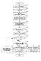
次に、上述のように構成された本実施形態に係る操舵支援装置101の処理手順を、図2、図3に示す説明図、及び図4に示すフローチャートを参照して説明する。 Next, a processing procedure of the
初めに、図4のステップS11において、仕切線検出部22は、カメラ21にて撮像された画像を取得する。ステップS12において、取得した画像から仕切線を検出する。なお、仕切線の検出方法は、既知の技術を採用することができ、詳細な説明を省略する。 First, in step S11 of FIG. 4, the partition
ステップS14において、基準位置設定部23は、車両の基準位置を設定する。この処理は、操作者(車両の乗員等)による入力操作により設定される。具体的には図2(a)に示すように車両旋回時の旋回内側後輪(符号P1)とする場合、図2(b)に示すように車両の後輪の車軸中心(符号P2)とする場合、図2(c)に示すように、車両旋回時の旋回外側前輪(符号P3)とする場合、或いは、図2(d)に示すように車両旋回時の旋回外側の前側コーナ部(符号P4)とする場合、のいずれかに設定される。なお、本実施形態では、上記の4通りの基準位置を例に挙げているが、これ以外の基準位置とすることも可能である。 In step S14, the reference
図2(a)に示すように、基準位置を車両旋回時の旋回内側後輪(車両は右側に車線変更するので、左側は旋回の内側である)とする場合には、符号D1に示す地点で基準位置が仕切線L1を跨ぐので、比較的遅いタイミングで仕切線跨ぎが検出される。 As shown in FIG. 2(a), when the reference position is the inside rear wheel when the vehicle turns (the left side is the inside of the turn because the vehicle changes lanes to the right), the point indicated by D1 Since the reference position crosses the partition line L1, the partition line crossing is detected at a relatively late timing.
図2(b)に示すように、基準位置を車両の後輪の車軸中心とする場合には、符号D2に示す地点で基準位置が仕切線L1を跨ぐことになる。更に、図2(c)に示すように、基準位置を車両旋回時の旋回外側前輪とする場合には、符号D3に示す地点で基準位置が仕切線L1を跨ぐことになり、図2(d)に示すように基準位置を車両旋回時の旋回外側の前側コーナ部とする場合には、符号D4に示す地点で基準位置が仕切線L1を跨ぐことになる。操作者は、上記した4通りの基準点から、所望の基準位置を選択して設定する。 As shown in FIG. 2B, when the reference position is set to the axle center of the rear wheel of the vehicle, the reference position crosses the partition line L1 at the point indicated by reference sign D2. Further, as shown in FIG. 2(c), when the reference position is the outside front wheel during turning of the vehicle, the reference position crosses the partition line L1 at the point indicated by reference sign D3, and FIG. When the reference position is set to the front corner portion on the outside of the turn when the vehicle turns as shown in (), the reference position crosses the partition line L1 at the point indicated by reference sign D4. The operator selects and sets a desired reference position from the above four reference points.
ステップS15において、仕切線跨ぎ判断部25は、仕切線L1と基準位置との、横方向の距離を演算する。即ち、仕切線検出部22で検出された仕切線L1から車両の基準位置までの、横方向の距離(これを、x1とする)を演算する。 In step S15, the partition line
ステップS16において、仕切線跨ぎ判断部25は、横方向距離x1がゼロになったか否かを判断する。この処理では、横方向距離x1=0の場合には、基準位置が仕切線L1を跨いだものと判断する。具体的には、基準位置として図2(a)に示すように「車両旋回時の旋回内側後輪(符号P1)」が設定されている場合には、符号D1に示す時点でx1=0となり、基準位置が仕切線L1を跨いだものと判断される。 In step S16, the partition line
ステップS17において、車線変更方向検出部24は、舵角センサ26で検出される舵角を取得する。 In step S17, the lane
ステップS18において、車線変更方向検出部24は、車両の舵角に基づき操舵中であるか、或いは補舵中であるかを判断し、更に、操舵中である場合には、ステップS19において、切込操舵であるか、或いは戻し操舵であるかを判断する。「切込操舵」とは、車両を現在の車線から右側の車線に車線変更する場合に、ステアリングを右側に回転させる操舵であり、「補舵」とは切込操舵が終了した後に、ステアリングの回転角度を一定に保持する状態である。また、「戻し操舵」とは、補舵が終了した後、ステアリングを左側に戻す操舵である。 In step S18, the lane change
そして、ステップS19で切込操舵中であると判断された場合には、ステップS20において、トルク発生制御部28は、切込操舵方向の摺動抵抗を高めるか、或いは、切込操舵方向の反対方向となる瞬時的な反力を発生させる。即ち、切込操舵方向の反対方向のトルクをステアリングに付与する。反力を発生させる例として、例えば図3(a)に示すように、ステアリングを右側に回転させたことにより基準位置が仕切線L1を跨いだ場合に、回転方向とは反対方向に瞬時的な反力を発生させる。こうすることにより、運転者に対して仕切線を跨いだことを認識させることができる。また、摺動抵抗を高める場合には、基準位置が仕切線L1を跨いだ際に、ステアリングを右方向へ回転させる際の摺動抵抗が高まるので、運転者に対して仕切線を跨いだことを認識させることができる。 Then, when it is determined in step S19 that the steering is in the cut steering direction, in step S20, the torque
一方、ステップS18で補舵中であると判断された場合には、ステップS22において、トルク発生制御部28は、直前の操舵方向の反対方向に向かう瞬時的な反力を発生させる。反力を発生させる例として、例えば図3(b)に示すように、ステアリングが左側に回転する方向に反力を発生させる。即ち、切込操舵方向が右方向であるので、この反対である左側に反力を発生させる。運転者はこの反力を感じることにより、基準位置が仕切線L1を跨いだことを認識できる。つまり、補舵中は運転者がステアリングを回転させないので、摺動抵抗を変化させることや瞬時的な反力を発生させても、運転者はこれを認識できない。そこで、切込操舵方向の反対方向に反力を発生させて、運転者に対し、仕切線を跨いだことを認識させている。 On the other hand, when it is determined in step S18 that the steering is being performed, in step S22, the torque
また、ステップS19で戻し操舵であると判断された場合には、ステップS21において、トルク発生制御部28は、戻し操舵方向の摺動抵抗を高めるか、或いは、戻し操舵方向の反対方向となる瞬時的な反力を発生させる。即ち、戻し操舵方向の反対方向のトルクをステアリングに付与する。反力を発生させる例として、例えば図3(c)に示すようにステアリングを左側に回転させることにより、基準位置が仕切線L1を跨いだ場合に、回転方向とは反対方向に瞬時的な反力を発生させる。こうすることにより、運転者に対して仕切線L1を跨いだことを認識させることができる。また、摺動抵抗を高める場合には、基準位置が仕切線L1を跨いだ際に、ステアリングを左方向へ戻す際の摺動抵抗が高まるので、運転者に対して仕切線L1を跨いだことを認識させることができる。 Further, when it is determined that the return steering is performed in step S19, in step S21, the torque
こうして、切込操舵中、補舵中、及び戻し操舵中のそれぞれの状況に適したトルクをステアリングに付与することにより、車両の基準位置が仕切線L1を跨いだことを認識させることができるのである。 In this way, it is possible to recognize that the reference position of the vehicle straddles the partition line L1 by applying torque to the steering wheel that is suitable for each of the steering, the auxiliary steering, and the return steering. is there.
このようにして、第1実施形態に係る操舵支援装置101では、車両の基準位置が設定されると、この基準位置が仕切線L1を跨いだか否かが判断される。そして、仕切線L1を跨いだことが検出された場合には、切込操舵中、補舵中、或いは戻し操舵中が判断され、それぞれの状況に応じて、ステアリングにトルクを付与し、仕切線L1を跨いだことを運転者に認識させる。 In this way, in the
従って、運転者に対して車両の基準位置が仕切線L1を跨いだことを確実に認識させることができ、車線変更時や高速道路の本線への合流時等において、車線を逸脱することなく安定的に目標とする車線に進入することが可能となる。 Therefore, the driver can be surely recognized that the reference position of the vehicle crosses the partition line L1, and the driver can be stable without deviating from the lane when changing lanes or merging into the main line of the expressway. It is possible to enter the target lane.
更に、基準位置設定部23では、操作者の設定入力により、車両の基準位置を適宜設定することが可能である。即ち、前述の図2(a)のように車両旋回時の旋回内側後輪とすることや、図2(b)のように車両の後輪の車軸中心とすることや、図2(c)のように車両旋回時の旋回外側前輪とすることや、或いは、図2(d)のように車両旋回時の旋回外側の前側コーナ部とすることにより、仕切線L1を跨いだことを認識させるタイミングを変化させることができる。具体的には、図2(d)、(c)、(b)、(a)の順で、仕切線L1を跨いだことを検出するタイミングが早くなる。 Further, the reference
従って、仕切線を跨いだことを早い時点で知りたい場合には、図2(d)に示すように、車両旋回時の旋回外側の前側コーナ部を基準位置として設定すればよい。これとは反対に、仕切線を跨いだことを遅い時点で知りたい場合には、図2(a)に示すように、車両旋回時の旋回内側後輪を基準位置として設定すればよい。 Therefore, if it is desired to know at an early point that the vehicle has crossed the partition line, the front corner portion on the outside of turning when the vehicle turns can be set as the reference position, as shown in FIG. 2D. On the contrary, when it is desired to know that the vehicle has crossed the partition line at a later time, the turning inner rear wheel at the time of turning the vehicle may be set as the reference position, as shown in FIG.
即ち、車両の基準位置を、車両旋回時の旋回内側後輪、車両の後輪の車軸中心、車両旋回時の旋回外側前輪、及び、車両旋回時の旋回外側の前側コーナ部、のいずれか一つに選択して設定することができるので、運転者に適した好適な基準位置を設定することが可能となる。 That is, the reference position of the vehicle is set to one of the inside rear wheel when the vehicle is turning, the axle center of the rear wheel of the vehicle, the outside front wheel when the vehicle is turning, and the outside front corner when the vehicle is turning. Since any one of them can be selected and set, a suitable reference position suitable for the driver can be set.
[第2実施形態の説明]
次に、本発明の第2実施形態について説明する。図5は、第2実施形態に係る操舵支援装置の構成を示すブロック図である。図5に示すように、第2実施形態に係る操舵支援装置102は、図1に示した操舵支援装置101と対比して、基準位置設定部23に車輪速センサ31が接続されている点で相違する。それ以外の構成は、図1と同様であるので、同一符号を付して構成説明を省略する。[Description of Second Embodiment]
Next, a second embodiment of the present invention will be described. FIG. 5 is a block diagram showing the configuration of the steering assist device according to the second embodiment. As shown in FIG. 5, the
基準位置設定部23は、車輪速センサ31で検出される走行速度に基づき、走行速度が速い順に、図2(d)、(c)、(b)、(a)の順に基準位置を設定する。具体的には、走行速度に3つの閾値速度Vth1、Vth2、Vth3(但し、Vth1>Vth2>Vth3)を設定し、走行速度V1がV1≧Vth1の場合には、図2(d)のように車両旋回時の旋回外側の前側コーナ部を基準位置する。走行速度V1がVth1>V1≧Vth2の場合には、図2(c)のように車両旋回時の旋回外側前輪を基準位置とする。走行速度V1がVth2>V1≧Vth3の場合には、図2(b)のように車両の後輪の車軸中心を基準位置とする。更に、走行速度V1がVth3>V1の場合には、図2(a)のように車両旋回時の旋回内側後輪を基準位置とする。 Based on the traveling speed detected by the
即ち、走行速度が速いほど基準位置を、車両旋回時の旋回外側の前側コーナ部、車両旋回時の旋回外側前輪、車両の後輪の車軸中心、車両旋回時の旋回内側後輪、の順に設定する。こうすることにより、走行速度が速いほど、より早い時点で仕切線を跨いだことを認識できるので、運転者は円滑に車線変更、或いは高速道路の本線への進入を行うことができる。 That is, the higher the traveling speed, the more the reference position is set in the order of the front corner portion on the outside of the turn when the vehicle turns, the front wheel on the outside of the turn when the vehicle turns, the center of the axle of the rear wheel of the vehicle, and the inside rear wheel when the vehicle turns. To do. By doing so, it is possible to recognize that the higher the traveling speed is, the more the vehicle crosses the partition line at an earlier point in time, so that the driver can smoothly change lanes or enter the main line of the expressway.
以下、第2実施形態に係る操舵支援装置102の処理手順を図6に示すフローチャートを参照して説明する。初めに、図6のステップS31において、仕切線検出部22は、カメラ21にて撮像された画像を取得する。ステップS32において、取得した画像から仕切線を検出する。 Hereinafter, the processing procedure of the
ステップS33において、基準位置設定部23は、車輪速センサ31より車両の走行速度を取得する。 In step S33, the reference
ステップS34において、基準位置設定部23は、車両の基準位置を設定する。この処理は、車両の走行速度に基づいて設定される。具体的には、上述したように、走行速度が速い順に、図2(d)、(c)、(b)、(a)の順に基準位置を設定する。その後、ステップS35〜S42の処理を実行する。なお、ステップS35〜S42の処理は、図4に示したステップS15〜S22の処理と同様であるので、説明を省略する。 In step S34, the reference
このように、第2実施形態に係る操舵支援装置102では、前述した第1実施形態と同様に、基準位置設定部23にて設定された基準位置が仕切線L1を跨いだ際に、ステアリングにトルクが付与されるので、運転者は仕切線L1を跨いだことを認識することができる。更に、第2実施形態では、車両の走行速度に応じて基準位置が設定される。即ち、走行速度V1がV1≧Vth1の場合には車両旋回時の旋回外側の前側コーナ部を基準位置とし、走行速度V1がVth1>V1≧Vth2の場合には車両旋回時の旋回外側前輪を基準位置とする。走行速度V1がVth2>V1≧Vth3の場合には車両の後輪の車軸中心を基準位置とし、走行速度V1がVth3>V1の場合には車両旋回時の旋回内側後輪を基準位置とする。 As described above, in the
従って、例えば、車両を高速で運転しており、V1≧Vth1である場合には、図2(d)の符号D4に示すように、早い時点でステアリングにトルクが付与されるので、運転者は早い時点で仕切線L1を跨いだことを認識できる。その結果、その後のステアリング操作を円滑に行うことが可能となる。 Therefore, for example, when the vehicle is being driven at a high speed and V1≧Vth1, as shown by the symbol D4 in FIG. 2D, the torque is applied to the steering wheel at an early point, so the driver It is possible to recognize that the partition line L1 is crossed at an early point. As a result, the subsequent steering operation can be smoothly performed.
[第3実施形態の説明]
次に、本発明の第3実施形態について説明する。図7は、第3実施形態に係る操舵支援装置の構成を示すブロック図である。図7に示すように、第3実施形態に係る操舵支援装置103は、図1に示した操舵支援装置101と対比して、基準位置設定部23に、後続車検出部32が接続されている点、及び車両にLRF(Laser Range Finder)33が搭載されている点で相違する。それ以外の構成は、図1と同様であるので、同一符号を付して構成説明を省略する。[Description of Third Embodiment]
Next, a third embodiment of the present invention will be described. FIG. 7 is a block diagram showing the configuration of the steering assist device according to the third embodiment. As shown in FIG. 7, in the
LRF33は、赤外線レーザを発振して対象物に照射し、その反射信号を検出することにより対象物までの距離を測定する。後続車検出部32は、LRF33で検出された信号に基づいて、車両が進入しようとする走行路を走行する後続車両を検出する。更に、後続車両までの距離(以下、「車間距離」という)を検出する。例えば、車両が現在の走行車線から右側の車線に車線変更する際には、右側の車線(車両が進入する走行路)の後方を走行する後続車両、及びこの後続車両までの距離である車間距離を検出する。 The
基準位置設定部23は、後続車検出部32で検出される車間距離に基づき、車間距離が短い順に、図2(d)、(c)、(b)、(a)の順に基準位置を設定する。具体的には、車間距離に3つの閾値距離Zth1、Zth2、Zth3(但し、Zth1<Zth2<Zth3)を設定し、車間距離Z1がZ1≦Zth1の場合には、図2(d)のように車両旋回時の旋回外側の前側コーナ部を基準位置とする。車間距離ZV1がZth1<Z1≦Zth2の場合には、図2(c)のように車両旋回時の旋回外側前輪を基準位置とする。車間距離Z1がZth2<Z1≦Zth3の場合には、図2(b)のように車両の後輪の車軸中心を基準位置とする。更に、車間距離Z1がZth3<Z1の場合及び後続車両が存在しない場合には、図2(a)のように車両旋回時の旋回内側後輪を基準位置とする。 The reference
即ち、基準位置設定部23は、車間距離が短いほど基準位置を、車両旋回時の旋回外側の前側コーナ部、車両旋回時の旋回外側前輪、車両の後輪の車軸中心、車両旋回時の旋回内側後輪、の順に設定する。こうすることにより、車間距離Z1が短いほど、早めに仕切線を跨いだことを認識できるので、運転者は円滑に車線変更を行うことができる。 That is, the reference
次に、第3実施形態に係る操舵支援装置103の処理手順を図8に示すフローチャートを参照して説明する。初めに、図8のステップS51において、仕切線検出部22は、カメラ21にて撮像された画像を取得する。ステップS52において、取得した画像から仕切線を検出する。 Next, the processing procedure of the
ステップS53において、後続車検出部32は、LRF33で検出される信号に基づいて、後続車両が存在するか否かを判断する。更に、後続車両が存在する場合には、この後続車両までの距離を検出する。 In step S53, the following
ステップS54において、基準位置設定部23は、車両の基準位置を設定する。この処理は、後続車両との車間距離Z1に基づいて基準位置を設定する。具体的には、上述したように、車間距離Z1が短い順に、図2(d)、(c)、(b)、(a)となるように基準位置を設定する。その後、ステップS55〜S62の処理を実行する。なお、ステップS55〜S62の処理は、図4に示したステップS15〜S22の処理と同様であるので、説明を省略する。 In step S54, the reference
このように、第3実施形態に係る操舵支援装置103では、前述した第1実施形態と同様に、基準位置設定部23にて設定された基準位置が仕切線L1を跨いだ際に、ステアリングにトルクが付与されるので、運転者は仕切線L1を跨いだことを認識することができる。 As described above, in the
更に、第3実施形態では、後続車両との間の車間距離Z1に応じて基準位置が設定される。即ち、車間距離Z1がZ1≦Zth1の場合には車両旋回時の旋回外側の前側コーナ部を基準位置とし、車間距離Z1がZth1<Z1≦Zth2の場合には車両旋回時の旋回外側前輪を基準位置とする。車間距離Z1がZth2<Z1≦Zth3の場合には車両の後輪の車軸中心を基準位置とし、車間距離Z1がZth3<Z1の場合、及び後続車両が存在しない場合には車両旋回時の旋回内側後輪を基準位置とする。 Furthermore, in the third embodiment, the reference position is set according to the inter-vehicle distance Z1 with the following vehicle. That is, when the inter-vehicle distance Z1 is Z1≦Zth1, the front corner portion on the outside of the turning when the vehicle is turning is the reference position, and when the inter-vehicle distance Z1 is Zth1<Z1≦Zth2, the turning outer front wheel is the reference. Position. When the inter-vehicle distance Z1 is Zth2<Z1≦Zth3, the center of the axle of the rear wheel of the vehicle is used as a reference position, and when the inter-vehicle distance Z1 is Zth3<Z1 and there is no following vehicle, the inside of the turning of the vehicle turns. The rear wheel is the reference position.
従って、例えば、右側の車線の後方に後続車両が存在し、該後続車両との間の車間距離Z1が、Z1≦Zth1である場合には、図2(d)の符号D4に示すように、早い時点でステアリングにトルクが付与されるので、運転者は早い時点で仕切線L1を跨いだことを認識できる。その結果、接近しつつある後続車両に対して影響を与えることなく、円滑に車線を変更することが可能となる。 Therefore, for example, when there is a following vehicle behind the right lane and the following vehicle distance Z1 is Z1≦Zth1, as shown by reference numeral D4 in FIG. 2(d), Since torque is applied to the steering wheel at an early point, the driver can recognize that the partition line L1 is crossed at an early point. As a result, the lane can be smoothly changed without affecting the following vehicle that is approaching.
[第4実施形態の説明]
次に、本発明の第4実施形態について説明する。図9は、第4実施形態に係る操舵支援装置の構成を示すブロック図である。図9に示すように、第4実施形態に係る操舵支援装置104は、図1に示した操舵支援装置101と対比して、基準位置設定部23に運転者行動記憶部34が接続されている点で相違する。それ以外の構成は、図1と同様であるので、同一符号を付して構成説明を省略する。[Description of Fourth Embodiment]
Next, a fourth embodiment of the present invention will be described. FIG. 9 is a block diagram showing the configuration of the steering assist device according to the fourth embodiment. As shown in FIG. 9, the
運転者行動記憶部34は、運転者の過去のステアリング操作データを記憶する。操作データには、運転者が車線変更、或いは高速道路の本線に進入する際の、ステアリングを切込操舵するタイミング、車両が車線を跨いだ後の戻し操舵のタイミングに関するデータが含まれている。 The driver
基準位置設定部23は、運転者行動記憶部34に記憶されている過去の操作データに基づいて、車両の基準位置を設定する。具体的には、ステアリングを切込操舵する際の角速度が速い(所謂、急ハンドル)運転者については、図2(d)のように車両旋回時の旋回外側の前側コーナ部を基準位置に設定する。反対に、角速度が遅い運転者については、図2(a)のように、車両旋回時の旋回内側後輪を基準位置に設定する。更に、角速度の大きさに応じて、図2(b)のように車両の後輪の車軸中心を基準位置に設定したり、図2(c)のように車両旋回時の旋回外側前輪を基準位置に設定する。 The reference
即ち、運転者の過去のステアリング操作データに基づいて、基準位置を、車両旋回時の旋回内側後輪、車両の後輪の車軸中心、車両旋回時の旋回外側前輪、及び、車両旋回時の旋回外側の前側コーナ部、のいずれか一つに設定する。 That is, based on the driver's past steering operation data, the reference position is set to the inside rear wheel when the vehicle turns, the axle center of the rear wheel of the vehicle, the outside front wheel when the vehicle turns, and the turning when the vehicle turns. Set to one of the outer front corners.
次に、第4実施形態に係る操舵支援装置104の処理手順を図10に示すフローチャートを参照して説明する。初めに、図10のステップS71において、仕切線検出部22は、カメラ21にて撮像された画像を取得する。ステップS72において、取得した画像から仕切線を検出する。 Next, the processing procedure of the
ステップS73において、基準位置設定部23は、運転者行動記憶部34に記憶されている過去のステアリング操作データを参照する。 In step S73, the reference
ステップS74において、基準位置設定部23は、車両の基準位置を設定する。この処理は、前述したように、運転者が過去に車線変更或いは高速道路の本線に進入した際の、ステアリング操作に応じて、車両の基準位置を設定する。具体的には、上述したように、車線変更或いは高速道路の本線に進入する際のステアリングの角速度が速い順に、図2(d)、(c)、(b)、(a)となるように基準位置を設定する。その後、ステップS75〜S82の処理を実行する。なお、ステップS75〜S82の処理は、図4に示したステップS15〜S22の処理と同様であるので、説明を省略する。 In step S74, the reference
このように、第4実施形態に係る操舵支援装置104では、前述した第1実施形態と同様に、基準位置設定部23にて設定された基準位置が仕切線L1を跨いだ際に、ステアリングにトルクが付与されるので、運転者は仕切線L1を跨いだことを認識することができる。 As described above, in the
更に、第4実施形態では、運転者の過去のステアリング操作データに基づいて基準位置が設定される。即ち、前述したようにステアリングを切込操舵する際の角速度に応じて、図2(a)〜(d)に示した各基準位置のうちのいずれかが設定される。従って、例えば、ステアリングを速い速度で切込操舵する運転者の場合には、図2(d)の符号D4に示すように、早い時点でステアリングにトルクが付与されるので、運転者は早い時点で仕切線L1を跨いだことを認識できる。その結果、円滑に車線を変更することが可能となる。 Further, in the fourth embodiment, the reference position is set based on the driver's past steering operation data. That is, as described above, one of the reference positions shown in FIGS. 2A to 2D is set according to the angular velocity when the steering wheel is steered. Therefore, for example, in the case of a driver who steers the steering wheel at a high speed, torque is applied to the steering wheel at an early point, as indicated by reference numeral D4 in FIG. It can be recognized that the partition line L1 is crossed. As a result, it becomes possible to change lanes smoothly.
以上、本発明の操舵支援装置及び操舵支援方法を図示の実施形態に基づいて説明したが、本発明はこれに限定されるものではなく、各部の構成は、同様の機能を有する任意の構成のものに置き換えることができる。 Although the steering assist device and the steering assist method of the present invention have been described above based on the illustrated embodiment, the present invention is not limited to this, and the configuration of each unit is an arbitrary configuration having a similar function. Can be replaced with one.
11 仕切線跨ぎ検出部
12 トルク付与部
21 カメラ
22 仕切線検出部
23 基準位置設定部
24 車線変更方向検出部
25 仕切線跨ぎ判断部
26 舵角センサ
27 トルク発生器
28 トルク発生制御部
31 車輪速センサ
32 後続車検出部
33 LRF
34 運転者行動記憶部
101,102,103,104 操舵支援装置
V1 走行速度
Z1 車間距離
x1 横方向距離11 Partition Line
34 Driver
Claims (10)
Translated fromJapanese前記車両に設定した基準位置が仕切線を跨いだことを検出する仕切線跨ぎ検出部と、
前記車両に搭載される舵角センサにより切込操舵、補舵、及び戻し操舵を検出し、更に、前記基準位置が前記仕切線を跨いだ際に、切込操舵中或いは補舵中である場合には、切込操舵方向の反対方向の瞬時的なトルクを前記ステアリングに付与し、戻し操舵中である場合には、戻し方向の反対方向の瞬時的なトルクを前記ステアリングに付与するトルク付与部と、
を備えることを特徴とする操舵支援装置。A steering assist device for applying a momentary torque to a steering mounted on a vehicle when changing lanes,
And partition lines crossing detector detects that the reference position set inthe vehicle is straddling the partition lines,
Detecting the cut steering, Hokaji, and the return steering by the steering angle sensor mounted on thevehicle both, further, when the reference position straddling the partition lines are being cut steering or during Hokaji case, impart instantaneous torque in the opposite direction of the cut steering direction to the steering, when it is in the return steering,the torque applied to impart instantaneous torque in the opposite direction of the return direction to the steeringDepartment,
Steering assist device, characterized in thatit comprises a.
を特徴とする請求項1に記載の操舵支援装置。The partition line crossing detector, the reference position, the rear wheel opposite to the direction to changethe car line, the axle center of the rear wheel, the front wheel direction of the lane change, the front direction of the lane change The steering assist device according to claim 1, wherein any one of the corner portions is selected and set.
を特徴とする請求項6に記載の操舵支援装置。A direction for changing the lane of the reference position based on driver's past steering operation data, further comprising a driver's behavior storage unit for storing driver's past steering operation data. The rear wheel on the opposite side, the axle center of the rear wheel, the front wheel on the lane changing direction side, and the front corner portion on the lane changing direction side are set to any one of the following. 6. The steering assist device according to item 6.
を特徴とする請求項6に記載の操舵支援装置。The partition line crossing detection unit acquires the traveling speed of the vehicle, and the higher the traveling speed, the more the reference position is, the front side corner portion on the side for changing the lane, the front wheel on the side for changing the lane, the rear wheel. The steering assist device according to claim 6, wherein the axle center and the rear wheel on the side opposite to the lane changing direction are set in this order.
前記仕切線跨ぎ検出部は、前記車間距離が短いほど前記基準位置を、前記車線変更する方向側の前側コーナ部、前記車線変更する方向側の前輪、前記後輪の車軸中心、前記車線変更する方向とは反対側の後輪、の順に設定すること
を特徴とする請求項6に記載の操舵支援装置。The vehicle further includes a following vehicle detection unit for detecting an inter-vehicle distance between the vehicle and a following vehicle traveling on a traveling path.
The partition line straddling detection unit changes the lane as the vehicle distance decreases, the reference position, the front corner portion on the lane change direction side, the front wheel on the lane change direction side, the axle center of the rear wheel, and the lane change. The steering assist device according to claim 6, wherein the rear wheels are set in the order opposite to the direction.
舵角センサで検出される舵角に基づき、切込操舵、補舵、及び戻し操舵を検出する工程と、
車線変更時に前記基準位置が前記仕切線を跨いだ際に、切込操舵中或いは補舵中である場合には、切込操舵方向の反対方向の瞬時的なトルクをステアリングに付与し、戻し操舵中である場合には、戻し方向の反対方向の瞬時的なトルクをステアリングに付与する工程と、
を特徴とする操舵支援方法。When the lane is changed, a step of detecting that the reference position set on the vehicle crosses the partition line,
Based on the rudder angle detected by the rudder angle sensor, the step of detecting the in-turn steering, the auxiliary steering, and the return steering,
When the reference position crosses the partition lineat the time of changing lanes and when the steering wheel is in the steering operation or the auxiliary steering operation, a momentary torque in the opposite direction to the steering operation is applied to the steering wheel to return the steering wheel. If inside, applying a momentary torque in the opposite direction to the return direction to the steering wheel,
A steering assist method characterized by:
Priority Applications (1)
| Application Number | Priority Date | Filing Date | Title |
|---|---|---|---|
| JP2015195608AJP6716879B2 (en) | 2015-10-01 | 2015-10-01 | Steering support device and steering support method |
Applications Claiming Priority (1)
| Application Number | Priority Date | Filing Date | Title |
|---|---|---|---|
| JP2015195608AJP6716879B2 (en) | 2015-10-01 | 2015-10-01 | Steering support device and steering support method |
Publications (2)
| Publication Number | Publication Date |
|---|---|
| JP2017065582A JP2017065582A (en) | 2017-04-06 |
| JP6716879B2true JP6716879B2 (en) | 2020-07-01 |
Family
ID=58493842
Family Applications (1)
| Application Number | Title | Priority Date | Filing Date |
|---|---|---|---|
| JP2015195608AActiveJP6716879B2 (en) | 2015-10-01 | 2015-10-01 | Steering support device and steering support method |
Country Status (1)
| Country | Link |
|---|---|
| JP (1) | JP6716879B2 (en) |
Families Citing this family (1)
| Publication number | Priority date | Publication date | Assignee | Title |
|---|---|---|---|---|
| JP7207339B2 (en)* | 2020-01-20 | 2023-01-18 | いすゞ自動車株式会社 | Control device for lane departure prevention device |
Family Cites Families (11)
| Publication number | Priority date | Publication date | Assignee | Title |
|---|---|---|---|---|
| JPH10297519A (en)* | 1997-04-28 | 1998-11-10 | Mitsubishi Heavy Ind Ltd | Steering device |
| JP2002109694A (en)* | 2000-09-29 | 2002-04-12 | Mitsubishi Motors Corp | Driving support system |
| JP3697425B2 (en)* | 2002-04-19 | 2005-09-21 | 三菱電機株式会社 | Vehicle steering control device |
| JP4826441B2 (en)* | 2006-11-17 | 2011-11-30 | トヨタ自動車株式会社 | Vehicle warning system |
| JP5073323B2 (en)* | 2007-03-12 | 2012-11-14 | 本田技研工業株式会社 | Steering holding state determination device, driver arousal level estimation device, and proper course maintenance device |
| JP5251030B2 (en)* | 2007-08-06 | 2013-07-31 | 日産自動車株式会社 | Steering support device and steering support method |
| US8111147B2 (en)* | 2008-05-13 | 2012-02-07 | GM Global Technology Operations LLC | Lane departure warning and change assist system utilizing active materials |
| JP5359200B2 (en)* | 2008-11-05 | 2013-12-04 | トヨタ自動車株式会社 | Vehicle steering control device |
| US20120098657A1 (en)* | 2010-10-25 | 2012-04-26 | Oleg Bogatine | Tracking lane marker position through use of information-transmiting device |
| US9043045B2 (en)* | 2011-02-21 | 2015-05-26 | Toyota Jidosha Kabushiki Kaisha | Travel assist apparatus and travel assist method |
| JP6011304B2 (en)* | 2012-12-15 | 2016-10-19 | マツダ株式会社 | Lane maintenance support device |
- 2015
- 2015-10-01JPJP2015195608Apatent/JP6716879B2/enactiveActive
Also Published As
| Publication number | Publication date |
|---|---|
| JP2017065582A (en) | 2017-04-06 |
Similar Documents
| Publication | Publication Date | Title |
|---|---|---|
| JP6447639B2 (en) | Target route generation device and travel control device | |
| CN108216225B (en) | Collision avoidance assistance device | |
| CN111226267B (en) | Driving control method and driving control device for driving assistance vehicle | |
| EP2741270B1 (en) | Driving assistance apparatus and driving assistance method | |
| JP6316411B2 (en) | Image recognition apparatus and control method thereof | |
| EP3091338B1 (en) | Misrecognition determination device | |
| JP5949961B2 (en) | Driving assistance device | |
| JP6485328B2 (en) | Vehicle driving support device | |
| JP6917330B2 (en) | Parking support device | |
| JP5853552B2 (en) | Vehicle travel control device | |
| TWI755869B (en) | Inclined vehicle with FCW control | |
| CN114302839B (en) | Method for determining a path for avoiding a motor vehicle | |
| JP4531621B2 (en) | Vehicle travel safety device | |
| JP7047722B2 (en) | Steering judgment device and automatic driving system | |
| JP2011108016A (en) | Drive support device | |
| JP6348285B2 (en) | Steering control device | |
| JP6631289B2 (en) | Vehicle control system | |
| JP6304011B2 (en) | Vehicle travel control device | |
| JP5282590B2 (en) | Vehicle driving support device and vehicle driving support method | |
| WO2016110732A1 (en) | Target route generation device and travel control device | |
| JP2005332192A (en) | Steering support system | |
| JP2017074806A (en) | Steering support device and steering support method | |
| JP6716879B2 (en) | Steering support device and steering support method | |
| JP2020129331A (en) | Reverse run determination system, reverse run determination method, and reverse run determination program | |
| JP6288305B2 (en) | Target vehicle speed generation device and travel control device |
Legal Events
| Date | Code | Title | Description |
|---|---|---|---|
| A621 | Written request for application examination | Free format text:JAPANESE INTERMEDIATE CODE: A621 Effective date:20180827 | |
| A977 | Report on retrieval | Free format text:JAPANESE INTERMEDIATE CODE: A971007 Effective date:20190621 | |
| A131 | Notification of reasons for refusal | Free format text:JAPANESE INTERMEDIATE CODE: A131 Effective date:20190702 | |
| A521 | Written amendment | Free format text:JAPANESE INTERMEDIATE CODE: A523 Effective date:20190822 | |
| A131 | Notification of reasons for refusal | Free format text:JAPANESE INTERMEDIATE CODE: A131 Effective date:20200107 | |
| A521 | Written amendment | Free format text:JAPANESE INTERMEDIATE CODE: A523 Effective date:20200221 | |
| TRDD | Decision of grant or rejection written | ||
| A01 | Written decision to grant a patent or to grant a registration (utility model) | Free format text:JAPANESE INTERMEDIATE CODE: A01 Effective date:20200512 | |
| A61 | First payment of annual fees (during grant procedure) | Free format text:JAPANESE INTERMEDIATE CODE: A61 Effective date:20200525 | |
| R151 | Written notification of patent or utility model registration | Ref document number:6716879 Country of ref document:JP Free format text:JAPANESE INTERMEDIATE CODE: R151 |