JP6713155B2 - Beauty equipment and beauty unit - Google Patents
Beauty equipment and beauty unitDownload PDFInfo
- Publication number
- JP6713155B2 JP6713155B2JP2019557518AJP2019557518AJP6713155B2JP 6713155 B2JP6713155 B2JP 6713155B2JP 2019557518 AJP2019557518 AJP 2019557518AJP 2019557518 AJP2019557518 AJP 2019557518AJP 6713155 B2JP6713155 B2JP 6713155B2
- Authority
- JP
- Japan
- Prior art keywords
- unit
- pad
- facial
- user
- electrodes
- Prior art date
- Legal status (The legal status is an assumption and is not a legal conclusion. Google has not performed a legal analysis and makes no representation as to the accuracy of the status listed.)
- Active
Links
Images


Classifications
- A—HUMAN NECESSITIES
- A61—MEDICAL OR VETERINARY SCIENCE; HYGIENE
- A61H—PHYSICAL THERAPY APPARATUS, e.g. DEVICES FOR LOCATING OR STIMULATING REFLEX POINTS IN THE BODY; ARTIFICIAL RESPIRATION; MASSAGE; BATHING DEVICES FOR SPECIAL THERAPEUTIC OR HYGIENIC PURPOSES OR SPECIFIC PARTS OF THE BODY
- A61H23/00—Percussion or vibration massage, e.g. using supersonic vibration; Suction-vibration massage; Massage with moving diaphragms
- A61H23/02—Percussion or vibration massage, e.g. using supersonic vibration; Suction-vibration massage; Massage with moving diaphragms with electric or magnetic drive
- A—HUMAN NECESSITIES
- A61—MEDICAL OR VETERINARY SCIENCE; HYGIENE
- A61H—PHYSICAL THERAPY APPARATUS, e.g. DEVICES FOR LOCATING OR STIMULATING REFLEX POINTS IN THE BODY; ARTIFICIAL RESPIRATION; MASSAGE; BATHING DEVICES FOR SPECIAL THERAPEUTIC OR HYGIENIC PURPOSES OR SPECIFIC PARTS OF THE BODY
- A61H39/00—Devices for locating or stimulating specific reflex points of the body for physical therapy, e.g. acupuncture
- A—HUMAN NECESSITIES
- A61—MEDICAL OR VETERINARY SCIENCE; HYGIENE
- A61N—ELECTROTHERAPY; MAGNETOTHERAPY; RADIATION THERAPY; ULTRASOUND THERAPY
- A61N1/00—Electrotherapy; Circuits therefor
- A61N1/02—Details
- A61N1/04—Electrodes
- A—HUMAN NECESSITIES
- A61—MEDICAL OR VETERINARY SCIENCE; HYGIENE
- A61N—ELECTROTHERAPY; MAGNETOTHERAPY; RADIATION THERAPY; ULTRASOUND THERAPY
- A61N1/00—Electrotherapy; Circuits therefor
- A61N1/18—Applying electric currents by contact electrodes
- A61N1/32—Applying electric currents by contact electrodes alternating or intermittent currents
- A61N1/36—Applying electric currents by contact electrodes alternating or intermittent currents for stimulation
Landscapes
- Health & Medical Sciences (AREA)
- Veterinary Medicine (AREA)
- Public Health (AREA)
- General Health & Medical Sciences (AREA)
- Animal Behavior & Ethology (AREA)
- Life Sciences & Earth Sciences (AREA)
- Rehabilitation Therapy (AREA)
- Radiology & Medical Imaging (AREA)
- Nuclear Medicine, Radiotherapy & Molecular Imaging (AREA)
- Biomedical Technology (AREA)
- Engineering & Computer Science (AREA)
- Epidemiology (AREA)
- Pain & Pain Management (AREA)
- Physical Education & Sports Medicine (AREA)
- Electrotherapy Devices (AREA)
Description
Translated fromJapanese本発明は、美顔器具、および美顔ユニットに関する。 The present invention relates to a facial device and a facial unit.
従来、例えば下記特許文献1に示すように、使用者の顔面に物理的な刺激を与えて、疲労回復効果、および痩身効果を得ることで、美容に供する美顔器具が知られている。 BACKGROUND ART Conventionally, as shown in
この美顔器具では、使用者の顔面を被覆するマスクの内部に振動素子が設けられている。そして使用者がマスクを顔面に装着した状態で、振動素子が振動することで、前述した各効果を奏することができる。 In this facial beauty device, a vibrating element is provided inside a mask that covers the face of the user. When the user wears the mask on his/her face, the vibrating element vibrates, so that the above-described effects can be achieved.
しかしながら、特許文献1に記載の発明では、マスクが顔面を全体的に被覆するため、例えば長時間の使用等に際して、不快感を伴うおそれがあった。 However, in the invention described in
そこで本発明は、顔面の一部のみを被覆することで、使用に際する不快感を抑え、楽しみながら使用することができる美顔器具を提供することを目的とする。 Therefore, an object of the present invention is to provide a facial device that covers only a part of the face to suppress discomfort during use and allows the user to enjoy while using the device.
上記課題を解決するために、本発明の美顔器具は、使用者の顔面に装着されるとともに、使用者の頬部、およびその周辺を被覆するパッド部と、パッド部に設けられた複数の電極と、電極に電圧を印可する電源部と、を備えている。 In order to solve the above problems, the facial device of the present invention is mounted on the user's face, the user's cheek portion, and a pad portion that covers the cheek portion, and a plurality of electrodes provided on the pad portion. And a power supply unit for applying a voltage to the electrodes.
また、パッド部は左右一対設けられ、左右一対のパッド部が、電源部を有する連結部により、互いに連結されてもよい。 Also, a pair of left and right pad portions may be provided, and the pair of left and right pad portions may be connected to each other by a connecting portion having a power supply portion.
また、パッド部は、基部から先端部に向けて互いに異なる方向に延びる形状を呈してもよい。 Further, the pad portion may have a shape extending from the base portion toward the tip portion in different directions.
また、電源部は、パッド部の基部に取り付けられてもよい。 Further, the power supply unit may be attached to the base of the pad unit.
また、パッド部は、基部を通る略円弧状に延びる円弧状パッドと、基部から、円弧状パッドにおける円弧の内側に向けて延びる中間パッドと、を備えてもよい。 In addition, the pad portion may include an arcuate pad that extends in a substantially arcuate shape that passes through the base portion, and an intermediate pad that extends from the base portion toward the inside of the arc of the arcuate pad.
また、パッド部は、合成化合物により一体に形成されてもよい。 Moreover, the pad portion may be integrally formed of a synthetic compound.
また、連結部は、使用者が使用する際に、使用者の頭部又は首部を覆うように湾曲して延びるバンド部材であってもよい。 In addition, the connecting portion may be a band member that extends in a curved shape so as to cover the head or neck of the user when the user uses it.
また、パッド部は矩形状をなし、複数の電極は、正極および負極が、パッド部にそれぞれ2組設けられてもよい。 Further, the pad portion may have a rectangular shape, and the plurality of electrodes may be provided with two sets of positive electrode and negative electrode, respectively.
また、パッド部を連結部の両端部に連結する支持軸を備え、支持軸は、パッド部を連結部の両端部に対して回転可能に支持してもよい。 In addition, a support shaft that connects the pad portion to both ends of the connecting portion may be provided, and the support shaft may rotatably support the pad portion with respect to both end portions of the connecting portion.
また、パッド部のうち、電極が設けられた部分は、使用者の顔面のうち、眼の中心よりも左右方向における顔面の内側に位置する部分に接触してもよい。 The portion of the pad portion provided with the electrodes may contact a portion of the user's face located inside the face in the left-right direction with respect to the center of the eyes.
また、複数の駆動モードとしてウォーミングアップモード、トレーニングモード、およびクーリングダウンモードを備えるとともに、この順に複数の駆動モードが切り替わるように駆動し、トレーニングモードにおいて、電極に印可される電圧の周波数は、ウォーミングアップモードおよびクーリングダウンモードにおいて、電極に印可される電圧の周波数よりも高くなってもよい。 In addition, as a plurality of driving modes, a warming-up mode, a training mode, and a cooling-down mode are provided, and the driving is performed so that the plurality of driving modes are switched in this order. In the training mode, the frequency of the voltage applied to the electrodes is And in the cooling down mode, it may be higher than the frequency of the voltage applied to the electrodes.
また、ウォーミングアップモードにおいて、電極に印可される電圧の周波数は、クーリングダウンモードにおいて、電極に印可される電圧の周波数と互いに同等となっているとともに、トレーニングモードにおいて、電極に印可される電極の周波数の半分以下となってもよい。 The frequency of the voltage applied to the electrode in the warm-up mode is equal to the frequency of the voltage applied to the electrode in the cooling down mode, and the frequency of the electrode applied to the electrode in the training mode. May be less than half of.
また、電極に印可される電圧値を入力する操作部と、操作部に入力された電圧値に基づいて、電源部を制御する制御部と、を備えてもよい。 In addition, an operation unit that inputs a voltage value applied to the electrodes and a control unit that controls the power supply unit based on the voltage value input to the operation unit may be provided.
また、操作部から制御部に向けて、入力値を無線通信で伝達する無線通信部を備えてもよい。 Further, a wireless communication unit for transmitting an input value from the operation unit to the control unit by wireless communication may be provided.
また、上記課題を解決するために、本発明の美顔ユニットは、前述したいずれかの美顔器具と、電極に印可された電圧値の履歴を記録する記録部と、履歴を表示する履歴表示部と、を備えている。 In addition, in order to solve the above-mentioned problems, the facial treatment unit of the present invention includes one of the facial treatment devices described above, a recording unit that records the history of voltage values applied to the electrodes, and a history display unit that displays the history. , Are provided.
また、上記課題を解決するために、本発明の美顔ユニットは、前述したいずれかの美顔器具と、パッド部の内部に設けられ、使用者の筋肉量を計測する筋肉量計測部と、筋肉量計測部により計測された使用者の筋肉量を表示する筋肉量表示部と、を備えている。 In addition, in order to solve the above-mentioned problems, the facial beauty unit of the present invention includes one of the facial beauty instruments described above, a muscle mass measuring unit that is provided inside the pad unit, and measures a user's muscle mass, and a muscle mass. A muscle mass display unit that displays the muscle mass of the user measured by the measurement unit.
また、上記課題を解決するために、本発明の美顔ユニットは、前述したいずれかの美顔器具と、パッド部の内部に設けられ、使用者の肌水分量および肌弾力量のうち、少なくともいずれか一方を計測する肌状態計測部と、肌状態計測部により計測された肌の状態を表示する肌状態表示部と、を備えている。 Further, in order to solve the above-mentioned problems, the facial treatment unit of the present invention is provided in any one of the aforementioned facial treatment apparatus and the pad portion, and at least one of the skin moisture content and the skin elasticity of the user. A skin condition measuring unit for measuring one of them and a skin condition displaying unit for displaying the skin condition measured by the skin condition measuring unit are provided.
本発明の美顔器具によれば、パッド部に複数の電極が設けられている。このため、パッド部を使用者の顔面に装着した状態で、電源部から電極に向けて電圧を印可すると、使用者の顔面の筋肉に電気的な刺激を与えることができる。これにより、使用者の顔面に、疲労回復効果、および痩身効果を奏することができる。また、習慣的に継続して使用することにより、筋肉量を増加するとともに、血行が促進されることにより、引き締め効果や美肌効果も奏することができる。 According to the facial treatment instrument of the present invention, the pad portion is provided with the plurality of electrodes. Therefore, when a voltage is applied from the power supply unit to the electrodes with the pad unit attached to the user's face, electrical stimulation can be applied to the facial muscles of the user. As a result, a fatigue recovery effect and a slimming effect can be exerted on the user's face. Further, by habitually and continuously using it, the muscle mass is increased, and the blood circulation is promoted, so that the tightening effect and the beautiful skin effect can be achieved.
またパッド部が、使用者の頬部、およびその周辺を被覆している。このため、このパッド部を使用者の顔面に装着した際に、パッド部が使用者の顔面を全体的に被覆することがない。これにより、美顔器具が顔面の一部のみを被覆することで、使用に際する不快感を抑え、楽しみながら使用することができる。 The pad portion covers the cheek portion of the user and the periphery thereof. Therefore, when the pad portion is attached to the user's face, the pad portion does not entirely cover the user's face. As a result, since the facial device covers only a part of the face, the discomfort during use can be suppressed and the device can be used while having fun.
(第1実施形態)
以下に、本発明の第1実施形態に係る美顔器具1について、図1および図2を参照して説明する。なお、美顔ユニット100の構成については、第2実施形態で説明する。
本実施形態に係る美顔器具1は、使用者の顔面に装着され、顔面の筋肉に電気的な刺激を与えるEMS(Electrical Muscle Stimulation)機器である。(First embodiment)
The
The
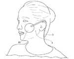
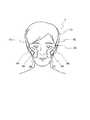
図1は、本発明の第1実施形態に係る美顔器具1を装着した状態を示す図であり、図2は、図1に示す美顔器具1の正面図である。
図1および図2に示すように、美顔器具1は、使用者の顔面に装着されるパッド部10と、パッド部10に設けられた複数の電極(図示せず)と、電極に電圧を印可する電源部30と、を備えている。FIG. 1 is a diagram showing a state in which a
As shown in FIGS. 1 and 2, the
パッド部10は、使用者の頬部、およびその周辺を被覆している。ここで、頬部の周辺とは、頬骨の周りと口元横の頬下部であり、より具体的には目尻の外側、目の下側、口元を結ぶ逆三角形の領域の内側を指している。
パッド部10は円形状を呈している。なお、パッド部10は楕円形上、半円形状、矩形状、三角形状、多角形状等の他の形状であってもよい。The
The
パッド部10は、使用者の頬部における左右に一対配置されている。電極は、パッド部10の任意の位置に配置することができる。
図2に示すように、左右一対のパッド部10は、電源部30を有する連結部5により、互いに連結されている。A pair of
As shown in FIG. 2, the pair of left and
連結部5は帯状をなしている。連結部5の中央部分に、電源部30が配置されている。電源部30には、電源スイッチ32と、美顔器具1の動作を表示する表示部34と、が配置されている。
図1に示すように、美顔器具1を使用する際には、使用者の頬部にパッド部10を貼り付けて、連結部5が耳にかかるように配置する。なお、電極、電源部30の構成、およびこれらの電気的な接続については、第2実施形態において詳述する。The connecting portion 5 has a strip shape. The
As shown in FIG. 1, when the
(第2実施形態)
次に、本発明の第2実施形態に係る美顔器具2、および美顔ユニット100について、図3から図7を参照して説明する。なお、この説明では上記実施形態と異なる部分についてのみ説明し、同一の構成については、その説明を省略する。(Second embodiment)
Next, the
図3は、本発明の第2実施形態に係る美顔器具2を示す正面図であり、図4は、美顔ユニット100のシステム構成図である。
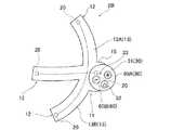
図3に示すように、パッド部10は、基部11から先端部12に向けて互いに異なる方向に延びる形状を呈している。図示の例では、パッド部10は三つ又形状を呈している。なお、パッド部10は三つ又以外の形状であってもよい。FIG. 3 is a front view showing the
As shown in FIG. 3, the
パッド部10は合成化合物により一体に形成されている。本実施形態では、パッド部10には合成樹脂材料であるシリコン材料が採用されている。なお、パッド部10の材料としては、合成樹脂材料に代えて、繊維材料等のその他の合成化合物を採用してもよい。
パッド部10は、基部11を通る略円弧状に延びる円弧状パッド13と、基部11から、円弧状パッド13における円弧の内側に向けて延びる中間パッド14と、を備えている。The
The
円弧状パッド13の両端部同士の周方向の大きさは、中心角が90°以下となっている。中間パッド14は、円弧状パッド13の周方向の中央部に接続されている。円弧状パッド13と中間パッド14との接続部分が、パッド部10の基部11になっている。
中間パッド14の大きさは、円弧状パッド13の周方向の大きさの半分程度になっている。円弧状パッド13および中間パッド14それぞれの幅方向の大きさは、互いに同等になっている。
パッド部10の基部11には、平面視で円形状を呈する取り付けパッド15が形成されている。Regarding the size of the
The size of the
A mounting
複数の電極20は、パッド部10の先端部12、および基部11に各別に設けられている。すなわち、本実施形態では4つの電極20がパッド部10に設けられている。電極20は電源部30と導線により電気的に接続されている。
電極20には、例えば銀インクを採用することができる。銀インクを採用することで、電源からの電力を効率的に電極20に伝達することができる。なお、電極20としては銀インク以外の材料を採用してもよい。The plurality of
For the
なお、複数の電極20は、パッド部10の先端部12、および基部11に各別に設けられていなくてもよい。すなわち、電極20の数量は4つに限定されることはなく、2つ以上の電極20が、パッド部10のうち、任意の位置に設けられていればよい。 The plurality of
電源部30は、正面視で円形状を呈する電源部本体31の内部に設けられている。電源部本体31は、パッド部10の取り付けパッド15に取り付けられている。電源部本体31には、電源部本体31を起動させる電源スイッチ32と、電源部本体31の起動を表示する表示灯33と、が設けられている。 The
図4に示すように、電源部本体31には、電源部30を制御する制御部40が設けられている。制御部40は、後述する操作部50に入力された電圧値に基づいて、電源部30を制御する。ここで、電圧値とは、電極20に印可される電圧の大きさと、周波数と、を意味する。 As shown in FIG. 4, the power supply unit
ここで、電極20に印可される電圧の基本周波数は4〜70Hzであり、そこで発生するパルス周波数は1kHz〜10KHzであることが好ましい。顔面の筋肉が繊細であることを考慮して設定することが好ましい。このような態様に限られず、任意に設定することができる。例えばパルス周波数を500KHz以上にしてもよい。 Here, it is preferable that the fundamental frequency of the voltage applied to the
美顔器具2はまた、電極20に印可される電圧を入力する操作部50と、操作部50から制御部40に向けて、電圧の入力値を無線通信で伝達する無線通信部60を備えている。
操作部50は、図示しないリモコン型のコントローラに内蔵されている。コントローラを操作することで、操作部50に所望する電圧を入力することができる。なお、操作部50は、例えば図示しないスマートフォンのアプリ等により実現してもよい。The
The
無線通信部60は、操作部50への入力値を、指令値として送信する送信部62と、送信部62からの指令値を受信して制御部40に伝達する受信部61と、を備えている。
送信部62は、コントローラの内部に設けられている。一方、受信部61は、電源部本体31の内部に設けられている。なお、操作部50をスマートフォンのアプリ等により実現する場合には、送信部62はスマートフォンの通信機能を利用することができる。The
The
次に、美顔器具2が用いられる美顔ユニット100について説明する。
美顔ユニット100は、美顔器具2と、電極20に印可された電圧値の履歴を記録する記録部70と、履歴を表示する履歴表示部71と、を備えている。
記録部70は、電源部本体31の内部に設けられている。履歴表示部71は例えば図示しないスマートフォンのアプリ等であり、記録部70との無線通信により、記録部70が記録した電圧値の履歴をスマートフォンの画面に表示する。Next, the
The
The
また、美顔ユニット100は、パッド部10の内部に設けられ、使用者の筋肉量を計測する計測部(筋肉量計測部)80と、計測措置により計測された使用者の筋肉量を表示する状態表示部(筋肉量表示部)81と、を備えている。
計測部80は、パッド部10の任意の位置に設けることができる。計測部80は、例えば、使用者の体内に向けて微弱な電気を流し、抵抗値を測定することで使用者の顔面の筋肉量を計測する。The
The measuring
状態表示部81は、例えば図示しないスマートフォンのアプリ等であり、計測部80との無線通信により、計測部80が計測した使用者の筋肉量をスマートフォンの画面に表示する。
ここで、操作部50、履歴表示部71、および状態表示部81は、一つのアプリにより実現してもよい。The
Here, the
また、計測部80は、使用者の肌水分量および肌弾力量のうち、少なくともいずれか一方を計測する肌状態計測部としての機能も有している。そして、状態表示部81は、計測部80により計測された肌の状態を表示する肌状態表示部としての機能も有している。
状態表示部81は、計測部80との無線通信により、計測部80が計測した使用者の肌水分量および肌弾力量をスマートフォンの画面に表示する。The measuring
The
すなわち、本実施形態では、筋肉量計測部と肌状態計測部とが、計測部80として一体に構成され、筋肉量表示部と肌状態表示部とが、状態表示部81として一体に構成されている。なお、このような態様に限られず、計測部80のうち、筋肉量計測部と肌状態計測部とを別々に構成してもよいし、状態表示部81のうち、筋肉量表示部と肌状態表示部とを別々に構成してもよい。 That is, in the present embodiment, the muscle mass measuring unit and the skin condition measuring unit are integrally configured as the measuring
次に、美顔器具2の使用方法について説明する。
図5は、美顔器具2を使用者に装着した状態を説明する図であり、図6は、使用者の顔面の筋肉の名称と位置を説明する図である。以下の説明において、顔面の筋肉の名称および位置の詳細については図6を参照されたい。
図5に示すように、美顔器具2を使用する際には、使用者の顔面における頬骨部B1に、パッド部10の基部11が位置するとともに、中間パッド14が眼窩下部に位置するように、パッド部10を配置する。Next, a method of using the
FIG. 5 is a diagram for explaining a state in which the
As shown in FIG. 5, when the
ここで、パッド部10を顔面に貼り付ける際には、パッド部10のうち、顔面と接触する面の全体に、例えばヒアルロン酸等の保湿成分を備えた導電性のジェルを塗布することが好ましい。
これにより、パッド部10を顔面に長時間貼り付けることができるとともに、ジェルを介して広範囲に電流を流すことができる。また、ジェルが保湿成分を備えているので、肌を保湿することもできる。Here, when the
As a result, the
そして、このように配置することで、円弧状パッド13のうち、基部11から上方に向けて延びる上側パッド13Aが、眼輪筋M1と側頭筋M2との間に沿って延びることとなる。
またこの際、円弧状パッド13のうち、基部11から下方に向けて延びる下側パッド13Bが、大頬骨筋M3に沿って、頬筋M4および口輪筋M5に向けて延びることとなる。
またこの際、中間パッド14が、眼輪筋M1に沿って、上唇挙筋M6に向けて延びることとなる。With this arrangement, the
At this time, the
Further, at this time, the
そして、この状態で、操作部50に所望する電圧値を入力すると、送信部62および受信部61を介して制御部40に指令値が伝達され、制御部40が指令値に基づいて電源部30を制御する。
これにより、電極20に使用者が所望した大きさ、および周波数の電圧が印可され、電極20から使用者の顔面の筋肉に電流が流れることとなる。この電流により筋肉が収縮することで、筋肉に刺激を与えることができる。Then, in this state, when a desired voltage value is input to the
As a result, a voltage having a magnitude and frequency desired by the user is applied to the
また、使用者は、例えばスマートフォンにより、電極20に印可された電圧値の履歴や、計測部80により計測された筋肉量を確認する。これにより、使用履歴や筋肉の成長度を定期的に確認することで、継続して使用するうえでの動機づけを得ることとなる。 In addition, the user confirms the history of the voltage value applied to the
(第3実施形態)
次に、本発明の第3実施形態に係る美顔器具3について、図8から図14を参照して説明する。なお、この説明では上記実施形態と異なる部分についてのみ説明し、同一の構成については、その説明を省略する。(Third Embodiment)
Next, the
図8は、美顔器具3の斜視図、図9は美顔器具3の正面図、図10は美顔器具3の右側面図である。
図8に示すように、美顔器具3は、ヘッドフォンを模した形状となっている。美顔器具3は、左右に一対設けられたパッド部90と、一対のパッド部90を連結する連結部91と、を備えている。連結部91には、電源部30が設けられている。FIG. 8 is a perspective view of the
As shown in FIG. 8, the
連結部91は、使用者が使用する際に、使用者の頭部又は首部を覆うように湾曲して延びるバンド部材である。
本実施形態では、連結部91は、使用者の頭部を覆うヘッドバンド92と、ヘッドバンド92の両端部から延びる一対のスライダーバンド93と、スライダーバンド93と連結された一対のハウジング94と、を備えている。なお、使用者の頭部を覆うヘッドバンド92に代えて、使用者の首部の後側を覆うネックバンドを採用してもよい。
以下の説明では、美顔器具3を使用する使用者の向きを基準にして、前後方向、左右方向、上下方向を定義する。The connecting
In the present embodiment, the connecting
In the following description, the front-back direction, the left-right direction, and the up-down direction are defined based on the orientation of the user who uses the
図9に示すように、ヘッドバンド92の正面視における厚み寸法は、ヘッドバンド92の位置により異なっている。ヘッドバンド92の厚み寸法は、中央部から両端部に向かうに従い漸次、大きくなっている。ヘッドバンド92の両端部に、電源部30および無線通信部60がそれぞれ内蔵されている。
図10に示すように、ヘッドバンド92の前後方向の幅寸法は、ヘッドバンド92の全域において均一になっている。As shown in FIG. 9, the thickness dimension of the
As shown in FIG. 10, the width dimension of the
図9に示すように、スライダーバンド93の正面視における厚み寸法は、ヘッドバンド92の厚み寸法よりも小さく、スライダーバンド93の全域において均一になっている。
図10に示すように、スライダーバンド93の前後方向の幅寸法は、ヘッドバンド92の幅寸法よりも小さく、スライダーバンド93の全域において均一になっている。As shown in FIG. 9, the thickness dimension of the
As shown in FIG. 10, the width dimension of the
スライダーバンド93はヘッドバンド92の内部に収容可能に配置され、使用者が選択するパッド部90の位置に従って、ヘッドバンド92から引き出されることで長さを調整可能となっている。
スライダーバンド93の長さが調整可能となっていることで、使用者の好みの位置にパッド部90を接触させることができる。The
Since the length of the
図9に示すように、ハウジング94は、スライダーバンド93の下端部に連結されている。ハウジング94にはパッド部90が支持軸95を介して連結されている。
支持軸95は、パッド部90を連結部91の両端部であるハウジング94に対して回転可能に支持している。ハウジング94は矩形状を呈している。支持軸95はハウジング94の内部に設けられている。As shown in FIG. 9, the
The
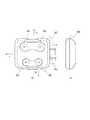
図11に示すようにパッド部90は矩形状をなしている。図11(a)は、パッド部90の側面視形状を示す図、図11(b)は、パッド部90の正面視形状を示す図である。
パッド部90は4辺のうちの2辺が湾曲している。パッド部90の周縁部のうち、前方に位置する前縁部は、上下方向の中央部が後方に向けて突となる曲線状に形成されている。パッド部90の周縁部のうち、後方に位置する後縁部は、上下方向の中央部が後方に向けて突となる曲線状に形成されている。パッド部90には複数の電極20が設けられている。As shown in FIG. 11, the
Two of the four sides of the
複数の電極20は、正極(+)および負極(−)が、パッド部90にそれぞれ2組設けられている。図示の例では、パッド部90の前側に、正極および負極が1組設けられ、パッド部90の後側に、正極および負極が1組設けられている。なお、電極20の配置状態は任意に変更することができる。例えば、電極20は正極(+)および負極(−)が1組だけ配置されてもよいし、3組以上配置されてもよい。 Two sets of positive electrodes (+) and negative electrodes (-) of the plurality of
次に美顔器具3の駆動モードについて図12を用いて説明する。図12は、美顔器具3の駆動モードを説明する図である。
図12に示すように、美顔器具3は、複数の駆動モードとしてウォーミングアップモード、トレーニングモード、およびクーリングダウンモードを備えている。そして、電源部30がONになると、ウォーミングアップモード、トレーニングモード、およびクーリングダウンモードの順に、複数の駆動モードが切り替わるように駆動する。Next, the drive mode of the
As shown in FIG. 12, the
トレーニングモードにおいて、電極20に印可される電圧の周波数は、ウォーミングアップモードおよびクーリングダウンモードにおいて、電極20に印可される電圧の周波数よりも高くなっている。全ての駆動モードにおいて、電極20に印可される電圧の振幅は、全て同等になっている。 The frequency of the voltage applied to the
ウォーミングアップモードにおいて、電極20に印可される電圧の周波数は、クーリングダウンモードにおいて、電極20に印可される電圧の周波数と互いに同等となっている。
ウォーミングアップモードにおいて、電極20に印可される電圧の周波数は、トレーニングモードにおいて、電極20に印可される電極20の周波数の半分以下となっている。In the warming up mode, the frequency of the voltage applied to the
In the warm-up mode, the frequency of the voltage applied to the
美顔器具3は、この3つの駆動モードをそれぞれ1分間ずつ駆動させ、3分間を1setとして、例えば3set分駆動する。本実施形態では各駆動モードの駆動時間は同等になっているが、駆動モード毎に駆動時間を変更してもよいし、set数を変更してもよい。駆動モードの調整は、制御部40が行う。また、操作部50を操作して、各駆動モードにおける駆動時間を使用者が変更してもよい。 The
次に、美顔器具3の使用状態について図13および図14を参照して説明する。図13は美顔器具3の使用態様の一例を示す図である。図14は、美顔器具3の使用態様の他の例を示す図である。
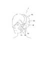
図13に示すように、美顔器具3を使用する場合には、ヘッドバンド92により頭頂部を覆うように、頭部に装着する。これにより、パッド部90が眼輪筋M1、大頬骨筋M3、頬筋M4それぞれにおける少なくとも一部を覆う(図6参照)。この状態で美顔器具3を駆動させることで、これらの筋肉に刺激を与えることができる。Next, a usage state of the
As shown in FIG. 13, when using the
次に、図14に示すように、図13に示す状態から、スライダーバンド93を伸ばすとともに、支持軸95回りに、スライダーバンド93に対してパッド部90を回転させる。これにより、パッド部90のうち、電極20が設けられた部分は、使用者の顔面のうち、眼の中心よりも左右方向における顔面の内側に位置する部分に接触する。
このとき、パッド部90は、眼輪筋M1、大頬骨筋M3、頬筋M4だけでなく、口輪筋M5や上唇挙筋M6の少なくとも一部を覆うようになる(図6参照)。これにより、より一層広範囲にわたって、電極20からの刺激を顔面に与えることができる。Next, as shown in FIG. 14, the
At this time, the
以上説明したように、美顔器具1、2、3によれば、パッド部10に複数の電極20が設けられている。このため、パッド部10を使用者の顔面に装着した状態で、電源部30から電極20に向けて電圧を印可すると、使用者の顔面の筋肉に電気的な刺激を与えることができる。これにより、使用者の顔面に、疲労回復効果、および痩身効果を与え、美容に供することができる。また、習慣的に継続して使用することにより、筋肉量を増加するとともに、血行が促進されることにより、引き締め効果や美肌効果も奏することができる。 As described above, according to the
またパッド部10が、使用者の頬部、およびその周辺を被覆している。このため、このパッド部10を使用者の顔面に装着した際に、パッド部10が使用者の顔面を全体的に被覆することがない。これにより、美顔器具1が顔面の一部のみを被覆することで、使用に際する不快感を抑え、楽しみながら使用することができる。 Moreover, the
また、第1実施形態に係る美顔器具1では、パッド部10は円形状を呈し、左右一対のパッド部10が、電源部30を有する連結部5により、互いに連結されている。このため、パッド部10の見栄えを良くするとともに、連結部5により一対のパッド部10同士が連結されていることで、美顔器具1の取り扱い性を向上することができる。 In the
また、第2実施形態に係る美顔器具2では、パッド部10が、基部11から先端部12に向けて互いに異なる方向に延びる形状を呈している。このため、このパッド部10を使用者の顔面に装着した際に、パッド部10のうち、複数の先端部12同士の間に空間が形成されることで、パッド部10が使用者の顔面を全体的に被覆することがない。 Moreover, in the
また、電源部30が、パッド部10の基部11に取り付けられているので、例えば電源部30がパッド部10の先端部12に取り付けられているような構成と比較して、重量バランスの偏りを少なくすることができる。これにより、美顔器具2を顔面に装着したときに、パッド部10が顔面から外れるのを抑制することができる。 Further, since the
また、パッド部10が、基部11を通る略円弧状に延びる円弧状パッド13と、基部11から、円弧状パッド13における円弧の内側に向けて延びる中間パッド14と、を備えている。
このため、使用者の顔面の頬骨部B1に、パッド部10の基部11が位置するようにパッド部10を装着すると、円弧状パッド13のうち、基部11から上方に向けて延びる上側パッド13Aが、眼輪筋M1と側頭筋M2との間に沿って延びることとなる。
またこの際、円弧状パッド13のうち、基部11から下方に向けて延びる下側パッド13Bが、大頬骨筋M3に沿って、頬筋M4および口輪筋M5に向けて延びることとなる。またこの際、中間パッド14が、眼輪筋M1に沿って、上唇挙筋M6に向けて延びることとなる。In addition, the
Therefore, when the
Further, at this time, among the
これにより、顔の表情の印象に対して大きく影響する眼輪筋M1、側頭筋M2、大頬骨筋M3、上唇挙筋M6、口輪筋M5および頬筋M4に対して、電気的な刺激を効率的に作用させることで、各筋肉が引き締まり、リフトアップ効果を得ることができる。すなわち、例えば顔面のうち、無作為に選択した部分に漠然と刺激を与えるような構成と比較して、より一層効果的に美顔器具2を美容に供することができる。 This electrically stimulates the orbicularis muscle M1, temporalis muscle M2, greater zygomaticus muscle M3, levator levator muscle M6, orbicularis orbicularis muscle M5, and buccal muscle M4, which greatly influence the impression of facial expressions. By efficiently acting, each muscle is tightened, and a lift-up effect can be obtained. That is, for example, the
また、パッド部10が合成化合物により一体に形成されているので、パッド部10を軽量化することができるとともに、例えば射出成型等により安価に製造することができる。
また、合成化合物のうち、シリコン材料を採用することで、使用者の肌への負担や環境負荷を小さくすることができる。In addition, since the
Further, by adopting the silicon material among the synthetic compounds, it is possible to reduce the burden on the user's skin and the environmental load.
また、美顔器具2が、電極20に印可される電圧値を入力する操作部50と、操作部50に入力された電圧値に基づいて、電源部30を制御する制御部40と、を備えている。このため、使用者のニーズに合わせて、電圧の大きさを変化させたり、電圧の周波数を変化させたりすることができる。これにより、美顔器具2が顔面の筋肉に与える刺激を多様にすることで、幅広い層の使用者に適した仕様とすることができる。
また、美顔器具2が無線通信部60を備えているので、操作部50を電源部30とは別に設けることが可能になり、電源部30の小型化および軽量化を実現することができる。The
In addition, since the
また、本実施形態に係る美顔ユニット100は、電極20に印可された電圧値の履歴を記録する記録部70と、履歴を表示する履歴表示部71と、を備えている。このため、使用者がこれまでに使用した時間や、その時の電圧値を定期的に確認することで、美顔器具2を継続して使用するための動機づけを得ることができる。 The
また、本実施形態に係る美顔ユニット100は、使用者の筋肉量を計測する計測部80と、計測部80により計測された使用者の筋肉量を表示する状態表示部81と、を備えている。このため、使用者が自身の筋肉の成長度を定期的に確認することで、美顔器具2を継続して使用するための動機づけをより一層顕著に得ることができる。 In addition, the
また、本実施形態に係る美顔ユニット100は、使用者の肌水分量および肌弾力量のうち、少なくともいずれか一方を計測する計測部80と、計測部80により計測された使用者の肌水分量および肌弾力量を表示する状態表示部81と、を備えている。このため、使用者が自身の肌状態の変化を定期的に確認することで、美顔器具2を継続して使用するための動機づけを更に得ることができる。 In addition, the
また、美顔器具3において、連結部91が、使用者の頭部又は首部を覆うように湾曲して延びるバンド部材であるので、連結部91により、パッド部90を確実に使用者の頭部に固定することができる。これにより、使用中にパッド部90が使用者の顔面から外れるのを防ぐことができる。 Further, in the
また、パッド部90が矩形状をなしているので、パッド部90の角部を顔面に局所的に接触させることにより、細かな筋肉で構成された顔面に対して、適切に刺激を与えることができる。
また、複数の電極20は、正極および負極が、パッド部90にそれぞれ2組設けられているので、電気が流れる経路を2つ設けることができ、効果的に顔面に電気刺激を与えることができる。Further, since the
In addition, since the positive electrode and the negative electrode of the plurality of
また、パッド部90を連結部91の両端部に連結する支持軸95を備え、支持軸95が、パッド部90を連結部91の両端部に対して回転可能に支持しているので、パッド部90を連結部91に対して回転することで、顔面のうち、パッド部90が接触する部分を任意に調整することができる。これにより、使用者の利便性を確保することができる。 Further, since the
また、パッド部90のうち、電極20が設けられた部分は、使用者の顔面のうち、眼の中心よりも左右方向における顔面の内側に位置する部分に接触しているので、特に眼輪筋M1に効果的に刺激を与えることで、加齢とともに弛みやすい目元のラインを引き締めることができる。 Further, in the
また、美顔器具3における複数の駆動モードとして、ウォーミングアップモード、トレーニングモード、およびクーリングダウンモードを備えるとともに、この順に複数の駆動モードが切り替わるように駆動する。
そして、ウォーミングアップモードおよびクーリングダウンモードにおいて、電極20に印可される電圧の周波数は、トレーニングモードにおいて、電極20に印可される電圧の周波数よりも小さくなっている。このため、繊細な顔の筋肉に対していきなり大きな刺激を与えることなく、ウォーミングアップモードにおいて、充分に筋肉をほぐしたのちに、トレーニングモードに移行することができる。In addition, as a plurality of drive modes in the
The frequency of the voltage applied to the
また、トレーニングモードの後に、即座に刺激を無くすのではなく、クーリングダウンモードで美顔器具3を動作させることで、トレーニングモードにより筋肉に生じた疲労物質の排出を促すことができる。これにより、美顔器具3を使用したことにより顔面にむくみが生じるのを抑えることができる。 Further, after the training mode, the stimulation is not immediately eliminated, but by operating the
また、ウォーミングアップモードにおいて、電極20に印可される電圧の周波数は、クーリングダウンモードにおいて、電極20に印可される電圧の周波数と互いに同等となっている。これにより、電源部30で生成する電圧のパターンを少なくして、電源部30の構成をシンプルにすることができる。 In the warming-up mode, the frequency of the voltage applied to the
また、ウォーミングアップモードにおいて、電極20に印可される電圧の周波数は、トレーニングモードにおいて、電極20に印可される電極20の周波数の半分以下となっている。これにより、ウォーミングアップモードおよびクーリングダウンモードと、トレーニングモードと、の違いを顕著にして、それぞれの駆動モードの効果を確実に奏功させることができる。 Further, the frequency of the voltage applied to the
なお、前述の実施形態は、本発明の代表的な実施形態を単に例示したものにすぎない。したがって、本発明の趣旨を逸脱しない範囲において、前述の実施形態に対して種々の変形を行ってもよい。 The above-described embodiment is merely an example of the representative embodiment of the present invention. Therefore, various modifications may be made to the above-described embodiment without departing from the spirit of the present invention.
例えば、上記第2実施形態においては、電源部30がパッドの基部11に取り付けられている構成を示したが、このような態様に限られない。電源部30はパッド部10のうち、基部11を除く部分に取り付けられてもよい。 For example, in the above-described second embodiment, the configuration in which the
また、上記第2実施形態においては、パッド部10が円弧状パッド13と中間パッド14とを備えている構成を示したが、このような態様に限られない。パッド部10はそれぞれが直線状に延びる三つ股状を呈してもよい。 Further, in the second embodiment described above, the
また、上記第2実施形態では、パッド部10が一体に形成されている構成を示したが、このような態様に限られない。パッド部10は複数の部材により構成されてもよい。
また、上記実施形態では、美顔器具2が操作部50と制御部40とを備えている構成を示したが、このような態様に限られない。美顔器具2は操作部50と制御部40とを備えなくてもよい。Further, in the above-described second embodiment, the configuration in which the
Further, in the above-described embodiment, the
また、上記実施形態では、美顔器具2が無線通信部60を備えている構成を示したが、このような態様に限られない。美顔器具2は無線通信部60を備えなくてもよい。この場合には、例えば図7に示す変形例に係る美顔器具2Bのように、操作部50A、50Bを直接、電源部本体31に設けてもよい。 Moreover, in the said embodiment, although the
また、上記実施形態では、美顔ユニット100が、記録部70、履歴表示部71、計測部80、および状態表示部81を備えている構成を示したが、このような態様に限られない。美顔ユニット100は、記録部70、履歴表示部71、計測部80、および状態表示部81を備えなくてもよい。 Further, in the above-described embodiment, the
また、上記第3実施形態で説明した駆動モードについては、任意に変更することができる。たとえば、ウォーミングアップモードおよびクーリングダウンそれぞれにおいて、電極20に印可される電圧の周波数を、互いに異ならせてもよい。この場合には、ウォーミングアップモードにおいて、電極20に印可される電圧の周波数を、クーリングダウンにおいて、電極20に印可される電圧の周波数よりも大きくしてもよいし、その逆にしてもよい。
また、各駆動モードにおいて、電極20に印可される電圧の周波数を、時間の経過とともに変化させてもよい。Further, the drive mode described in the third embodiment can be arbitrarily changed. For example, the frequencies of the voltages applied to the
Further, in each drive mode, the frequency of the voltage applied to the
また、前述した変形例に限られず、これらの変形例を選択して適宜組み合わせてもよいし、その他の変形を施してもよい。 Further, the present invention is not limited to the above-described modified examples, and these modified examples may be selected and appropriately combined, or other modifications may be performed.
1、2、2B、3 美顔器具
10、90 パッド部
11 基部
12 先端部
13 円弧状パッド
14 中間パッド
20 電極
30 電源部
40 制御部
50 操作部
60 無線通信部
70 記録部
71 履歴表示部
80 計測部(筋肉量計測部、肌状態計測部)
81 状態表示部(筋肉量表示部、肌状態表示部)
100 美顔ユニット1, 2, 2B, 3
81 Status display (muscle mass display, skin condition display)
100 beautiful face unit
Claims (10)
Translated fromJapanese前記パッド部に設けられた複数の電極と、前記電極に電圧を印可する電源部と、を備え、
複数の前記電極における正極および負極からなる組が前記パッド部にそれぞれ2組設けられているとともに、前記パッド部における一の縁部に前記電極の正極および負極からなる組が1組設けられ、前記一の縁部と対向する他の縁部に前記電極の正極および負極からなる組の他の1組が設けられ、
前記パッド部は一対設けられ、
左右一対の前記パッド部が、前記電源部を有する連結部により、互いに連結され、
前記連結部は、使用者が使用する際に、使用者の頭部又は首部を覆うように湾曲して延びるバンド部材であるとともに、
使用者の頭部を覆うヘッドバンドと、
ヘッドバンドの両端部から延びる一対のスライダーバンドと、を備え、
前記スライダーバンドは、前記ヘッドバンドの内部に収容可能に配置され、使用者が選択する前記パッド部の位置に従って、前記ヘッドバンドから引き出されることで、前記ヘッドバンドから引き出される長さを調整可能となっている美顔器具。While being worn on the user's face, the cheek of the user, and arectangular pad portion that covers the periphery thereof,
A plurality of electrodes provided on the pad section, and a power supply section for applying a voltage to the electrodes,
Two sets of positive electrodes and negative electrodes of the plurality of electrodes are respectively provided on the pad portion, and one set of positive electrodes and negative electrodes of the electrodes is provided on one edge of the pad portion. Another pair of the pair of the positive electrode and the negative electrode of the electrode is provided on the other edge portion facing the one edge portion,
A pair of the pad portions are provided,
The pair of left and right pad portions are connected to each other by a connecting portion having the power supply portion,
The connecting portion, when used by the user, is a band member that extends in a curved manner so as to cover the head or neck of the user,
A headband that covers the user's head,
A pair of slider bands extending from both ends of the headband,
The slider band is arranged so as to be able to be housed inside the headband, and the length pulled out from the headband can be adjusted by being pulled out from the headband according to the position of the pad portion selected by the user. Facial equipment that has become.
前記支持軸は、前記パッド部を前記連結部の両端部に対して回転可能に支持することを特徴とする請求項1に記載の美顔器具。A support shaft connecting the pad part to both ends of the connecting part,
The facial device according to claim1 , wherein the support shaft rotatably supports the pad portion with respect to both end portions of the connecting portion.
前記操作部に入力された電圧値に基づいて、前記電源部を制御する制御部と、を備えていることを特徴とする請求項1から5のいずれか1項に記載の美顔器具。An operation unit for inputting a voltage value applied to the electrode,
The facial treatment device according to any one of claims 1 to5 , further comprising: a control unit that controls the power supply unit based on a voltage value input to the operation unit.
前記電極に印可された電圧値の履歴を記録する記録部と、
前記履歴を表示する履歴表示部と、を備えていることを特徴とする美顔ユニット。The facial beauty device according to any one of claims 1 to7 ,
A recording unit for recording the history of voltage values applied to the electrodes,
A facial display unit, comprising: a history display unit that displays the history.
前記パッド部の内部に設けられ、使用者の筋肉量を計測する筋肉量計測部と、
前記筋肉量計測部により計測された使用者の筋肉量を表示する筋肉量表示部と、を備えた美顔ユニット。The facial beauty device according to any one of claims 1 to7 ,
A muscle mass measuring unit provided inside the pad unit for measuring the muscle mass of the user,
A facial beauty unit comprising: a muscle mass display unit that displays the muscle mass of the user measured by the muscle mass measurement unit.
前記パッド部の内部に設けられ、使用者の肌水分量および肌弾力量のうち、少なくともいずれか一方を計測する肌状態計測部と、
前記肌状態計測部により計測された肌の状態を表示する肌状態表示部と、を備えた美顔ユニット。
The facial beauty device according to any one of claims 1 to7 ,
A skin condition measuring unit provided inside the pad unit for measuring at least one of the skin moisture content and the skin elasticity of the user,
A skin condition display unit that displays the skin condition measured by the skin condition measuring unit.
Applications Claiming Priority (3)
| Application Number | Priority Date | Filing Date | Title |
|---|---|---|---|
| JP2018131054 | 2018-07-10 | ||
| JP2018131054 | 2018-07-10 | ||
| PCT/JP2019/017201WO2020012754A1 (en) | 2018-07-10 | 2019-04-23 | Facial appliance and facial unit |
Publications (2)
| Publication Number | Publication Date |
|---|---|
| JP6713155B2true JP6713155B2 (en) | 2020-06-24 |
| JPWO2020012754A1 JPWO2020012754A1 (en) | 2020-07-16 |
Family
ID=69142521
Family Applications (1)
| Application Number | Title | Priority Date | Filing Date |
|---|---|---|---|
| JP2019557518AActiveJP6713155B2 (en) | 2018-07-10 | 2019-04-23 | Beauty equipment and beauty unit |
Country Status (2)
| Country | Link |
|---|---|
| JP (1) | JP6713155B2 (en) |
| WO (1) | WO2020012754A1 (en) |
Families Citing this family (2)
| Publication number | Priority date | Publication date | Assignee | Title |
|---|---|---|---|---|
| JP2022098235A (en)* | 2020-12-21 | 2022-07-01 | B-by-C株式会社 | Facial equipment, control method thereof, and control program |
| JP7236754B2 (en)* | 2021-04-22 | 2023-03-10 | B-by-C株式会社 | BEAUTIFUL FACE ASSISTANCE SYSTEM, BEAUTIFUL FACE ASSISTANCE METHOD, AND BEAUTIFUL FACE ASSISTANCE PROGRAM |
Family Cites Families (6)
| Publication number | Priority date | Publication date | Assignee | Title |
|---|---|---|---|---|
| JP5128166B2 (en)* | 2007-04-17 | 2013-01-23 | ヤーマン株式会社 | Electrode pad |
| AU2008365106B2 (en)* | 2008-12-11 | 2015-02-05 | Bio-Medical Research Limited | Facial stimulation apparatus |
| KR20150126124A (en)* | 2014-05-02 | 2015-11-11 | 김수진 | head band to prevent drowsiness |
| US9333334B2 (en)* | 2014-05-25 | 2016-05-10 | Thync, Inc. | Methods for attaching and wearing a neurostimulator |
| JPWO2016135996A1 (en)* | 2015-02-27 | 2017-12-07 | 株式会社 Mtg | Muscle electrical stimulator |
| KR101824505B1 (en)* | 2016-06-28 | 2018-02-01 | 박순창 | facial region stimulation apparatus |
- 2019
- 2019-04-23JPJP2019557518Apatent/JP6713155B2/enactiveActive
- 2019-04-23WOPCT/JP2019/017201patent/WO2020012754A1/ennot_activeCeased
Also Published As
| Publication number | Publication date |
|---|---|
| JPWO2020012754A1 (en) | 2020-07-16 |
| WO2020012754A1 (en) | 2020-01-16 |
Similar Documents
| Publication | Publication Date | Title |
|---|---|---|
| JP7405810B2 (en) | beauty mask | |
| JP7177015B2 (en) | beauty mask for eyes | |
| US20200114116A1 (en) | Therapeutic vibration system | |
| US20110139163A1 (en) | Vibration apparatus for stimulating paranasal sinuses | |
| CN111182831B (en) | Systems and methods for meditation enhancement | |
| JP6713155B2 (en) | Beauty equipment and beauty unit | |
| JP7051734B2 (en) | Headset for treatment and evaluation of medical conditions | |
| CN114259648A (en) | Face-beautifying mask | |
| JP2016515404A (en) | Headset for treatment and evaluation of medical conditions | |
| US6575923B1 (en) | Head-massaging apparatus | |
| CN117881459A (en) | Facial integral type muscle electric stimulation beauty appliance | |
| JP2002306604A (en) | Relaxation device | |
| JP2015231511A (en) | Electric therapy device | |
| KR102293630B1 (en) | Blood flow restriction and multidirectional electrical stimulation device for therapy and muscle strengthening | |
| JP2004216069A (en) | Facial appliance | |
| CN207012405U (en) | face slimming massager | |
| CN214105179U (en) | A facial dystonia relief device | |
| US11666505B2 (en) | Method for inducing a meditative state | |
| JP2021108906A (en) | Neck beauty appliance | |
| KR20210105501A (en) | Beauty apparatus | |
| CN214762892U (en) | Physical therapy device | |
| KR20200142817A (en) | A vibration belt | |
| EP4209249A1 (en) | Cosmetic mask, and cosmetic electric stimulator | |
| KR20250030694A (en) | Apparatus for correcting a hunched back | |
| WO2021056439A1 (en) | Micro-current v-face massager and control system |
Legal Events
| Date | Code | Title | Description |
|---|---|---|---|
| A521 | Request for written amendment filed | Free format text:JAPANESE INTERMEDIATE CODE: A523 Effective date:20191024 | |
| A621 | Written request for application examination | Free format text:JAPANESE INTERMEDIATE CODE: A621 Effective date:20191025 | |
| A871 | Explanation of circumstances concerning accelerated examination | Free format text:JAPANESE INTERMEDIATE CODE: A871 Effective date:20191025 | |
| A975 | Report on accelerated examination | Free format text:JAPANESE INTERMEDIATE CODE: A971005 Effective date:20191212 | |
| A131 | Notification of reasons for refusal | Free format text:JAPANESE INTERMEDIATE CODE: A131 Effective date:20191224 | |
| A521 | Request for written amendment filed | Free format text:JAPANESE INTERMEDIATE CODE: A523 Effective date:20200217 | |
| TRDD | Decision of grant or rejection written | ||
| A01 | Written decision to grant a patent or to grant a registration (utility model) | Free format text:JAPANESE INTERMEDIATE CODE: A01 Effective date:20200414 | |
| A61 | First payment of annual fees (during grant procedure) | Free format text:JAPANESE INTERMEDIATE CODE: A61 Effective date:20200513 | |
| R150 | Certificate of patent or registration of utility model | Ref document number:6713155 Country of ref document:JP Free format text:JAPANESE INTERMEDIATE CODE: R150 | |
| S531 | Written request for registration of change of domicile | Free format text:JAPANESE INTERMEDIATE CODE: R313531 | |
| R350 | Written notification of registration of transfer | Free format text:JAPANESE INTERMEDIATE CODE: R350 | |
| R250 | Receipt of annual fees | Free format text:JAPANESE INTERMEDIATE CODE: R250 | |
| R250 | Receipt of annual fees | Free format text:JAPANESE INTERMEDIATE CODE: R250 |