Movatterモバイル変換


[0]ホーム

URL:


JP6712112B2 - Programmable device application authentication system and authentication method - Google Patents

Programmable device application authentication system and authentication method
Download PDF

Info

Publication number
JP6712112B2
JP6712112B2JP2017037098AJP2017037098AJP6712112B2JP 6712112 B2JP6712112 B2JP 6712112B2JP 2017037098 AJP2017037098 AJP 2017037098AJP 2017037098 AJP2017037098 AJP 2017037098AJP 6712112 B2JP6712112 B2JP 6712112B2
Authority
JP
Japan
Prior art keywords
authentication
user
authentication data
data
fpga
Prior art date
Legal status (The legal status is an assumption and is not a legal conclusion. Google has not performed a legal analysis and makes no representation as to the accuracy of the status listed.)
Active
Application number
JP2017037098A
Other languages
Japanese (ja)
Other versions
JP2018142253A (en
Inventor
育生 大谷
育生 大谷
Current Assignee (The listed assignees may be inaccurate. Google has not performed a legal analysis and makes no representation or warranty as to the accuracy of the list.)
Nippon Telegraph and Telephone Corp
NTT Inc
Original Assignee
Nippon Telegraph and Telephone Corp
NTT Inc
Priority date (The priority date is an assumption and is not a legal conclusion. Google has not performed a legal analysis and makes no representation as to the accuracy of the date listed.)
Filing date
Publication date
Application filed by Nippon Telegraph and Telephone Corp, NTT IncfiledCriticalNippon Telegraph and Telephone Corp
Priority to JP2017037098ApriorityCriticalpatent/JP6712112B2/en
Publication of JP2018142253ApublicationCriticalpatent/JP2018142253A/en
Priority to JP2020057138Aprioritypatent/JP6904453B2/en
Priority to JP2020057137Aprioritypatent/JP6904452B2/en
Application grantedgrantedCritical
Publication of JP6712112B2publicationCriticalpatent/JP6712112B2/en
Activelegal-statusCriticalCurrent
Anticipated expirationlegal-statusCritical

Links

Images

Landscapes

Description

Translated fromJapanese

本発明は、データが書き換え自在なプログラマブルデバイスを用いて、ユーザの固有情報である認証データの認証を行うプログラマブルデバイス適用認証システム及び認証方法に関する。 The present invention relates to a programmable device application authentication system and an authentication method for authenticating authentication data, which is unique information of a user, by using a programmable device in which data can be rewritten.

従来、ユーザのID(Identification)やPW(Password)等の固有情報である認証データの認証を行う場合、所望データを電子回路に書き換え自在に置換して保持するFPGA(Field-Programmable Gate Array)等のプログラマブルデバイスを適用する。このプログラマブルデバイスを適用したプログラマブルデバイス適用認証システムは、ユーザの認証データとしてのIDやPWを、コンピュータがアクセスするDB(データベース)に保存するのではなく、例えばFPGAのハードウェア上に電子回路(回路ともいう)として保存する。そして、クライアント端末機からサーバを介して送信されてきたID及びPWを、FPGAに保存されたID及びPWとアンドを取り、一致すればOK、不一致でNG(No Good)とする認証を行う。 Conventionally, when authenticating authentication data that is unique information such as a user's ID (Identification) and PW (Password), an FPGA (Field-Programmable Gate Array), etc., in which desired data is rewritably replaced by an electronic circuit and held Apply the programmable device of. A programmable device application authentication system to which this programmable device is applied does not store the ID or PW as user authentication data in a DB (database) accessed by a computer, but instead, for example, on an FPGA hardware circuit (electronic circuit (circuit)). Also called as). Then, the ID and PW sent from the client terminal via the server are ANDed with the ID and PW stored in the FPGA, and if they match, authentication is OK, and if they do not match, NG (No Good) authentication is performed.

この種のFPGAに係るFPGAの適用例として非特許文献1,2の技術がある。非特許文献1は、FPGAを用いてソフトウェアの一部処理をオフロードして全体の処理を高速化する技術内容が記載されている。非特許文献2は、FPGAの書き換え時間についての技術内容が記載されている。 As an application example of an FPGA related to this type of FPGA, there are technologies ofNon-Patent Documents 1 and 2. Non-PatentDocument 1 describes the technical content of offloading a part of software processing by using FPGA to speed up the whole processing. Non-PatentDocument 2 describes the technical content of the rewriting time of the FPGA.

羽田野孝裕、他2名、「ネットワーク仮想化時代のソフト・ハード協調設計技術」、NTT技術ジャーナル、2015.11、p.37−41,[online],[平成29年2月13日検索]、インターネット〈URL: http://webcache.googleusercontent.com/search?q=cache:vb3cl4yUaDsJ:www.ntt.co.jp/journal/1511/files/jn201511037.pdf+&cd=1&hl=ja&ct=clnk&gl=jp〉Takahiro Hatano, 2 others, “Software/Hard Co-design Technology in the Network Virtualization Era”, NTT Technology Journal, 2015.11, p. 37-41, [online], [Search on February 13, 2017], Internet <URL: http://webcache.googleusercontent.com/search?q=cache:vb3cl4yUaDsJ:www.ntt.co.jp/journal /1511/files/jn201511037.pdf+&cd=1&hl=ja&ct=clnk&gl=jp〉Arthur Yang、「SPIフラッシュを使用した7シリーズFPGAのコンフィギュレーション」、XAPP586 (v1.0) 2012年5月30日,[online],[平成29年2月13日検索]、インターネット〈URL: https://webcache.googleusercontent.com/search?q=cache:bh_wWjxEzqcJ:https://japan.xilinx.com/support/documentation/application_notes/j_xapp586-spi-flash.pdf+&cd=1&hl=ja&ct=clnk&gl=jp〉Arthur Yang, "Configuration of 7 series FPGA using SPI flash", XAPP586 (v1.0) May 30, 2012, [online], [Search on February 13, 2017], Internet <URL: https ://webcache.googleusercontent.com/search?q=cache:bh_wWjxEzqcJ:https://japan.xilinx.com/support/documentation/application_notes/j_xapp586-spi-flash.pdf+&cd=1&hl=ja&ct=clnk&gl=jp 〉

しかし、ユーザがID及びPW等の認証データの追加、削除又は変更を行う場合、これらの処理を実行するための新しいIDやPWをFPGAに設定して回路化するコンフィギュレーションデータ(コンフィグデータという)をバイナリビットで生成する。この生成したコンフィグデータでFPGAの全回路を書き換える必要がある。この書き換え処理時には、ユーザへ提供する通信サービスを書き換え完了まで中断する必要がある。この中断のため、IDやPWの変更等の頻度が高い程にサービス中断が増えるという問題がある。サービス中断が増えると実用的なサービス運用が行えなくなってしまう。 However, when the user adds, deletes, or changes the authentication data such as ID and PW, configuration data (called configuration data) that sets a new ID or PW for executing these processes in the FPGA Is generated with binary bits. It is necessary to rewrite all the FPGA circuits with the generated configuration data. During this rewriting process, it is necessary to suspend the communication service provided to the user until the rewriting is completed. Due to this interruption, there is a problem that the service interruption increases as the frequency of changing the ID and PW increases. If the service interruption increases, it becomes impossible to operate the service practically.

本発明は、このような事情に鑑みてなされたものであり、ユーザのID及びPW等の認証データの追加、削除又は変更を行う際に、ユーザに提供する通信サービスの中断を抑制することができるプログラマブルデバイス適用認証システム及び認証方法を提供することを課題とする。 The present invention has been made in view of such circumstances, and it is possible to suppress interruption of a communication service provided to a user when adding, deleting or changing authentication data such as a user's ID and PW. An object is to provide a programmable device application authentication system and an authentication method that can be performed.

上記課題を解決するための手段として、請求項1に係る発明は、固有の認証データを電子回路に置換して保持するプログラマブルデバイス装置によって、端末機から送信されてきたユーザ固有の認証データを、前記電子回路として保持された認証データと比較して認証を行うプログラマブルデバイス適用認証システムであって、前記ユーザ固有の認証データをキャッシュするデータベースを有し、当該データベースにキャッシュされた認証データを、バッチ処理で前記プログラマブルデバイス装置に電子回路への置換を行わせるための転送を行い、この転送後に前記キャッシュされた認証データを削除する認証サーバを備え、前記認証サーバは、前記端末機からのユーザの認証データを受信した際に、前記データベースに同ユーザの認証データがキャッシュされていれば、当該受信した認証データを、当該キャッシュされた認証データと比較して認証を行い、キャッシュされていなければ前記プログラマブルデバイス装置に電子回路として保持された認証データと比較して認証を行わせることを特徴とするプログラマブルデバイス適用認証システムである。 As a means for solving the above problems, the invention according toclaim 1 provides a user-specific authentication data transmitted from a terminal by a programmable device device that replaces and holds the unique authentication data with an electronic circuit, A programmable device application authentication system that performs authentication by comparing with authentication data held as the electronic circuit, having a database that caches the user-specific authentication data, and batches the authentication data cached in the database. The processing includes a transfer for causing the programmable device device to perform replacement with an electronic circuit, and an authentication server that deletes the cached authentication data after the transfer is provided, and the authentication server is a user of the terminal device. When the authentication data of the same user is cached in the database when the authentication data is received, the received authentication data is compared with the cached authentication data, and authentication is performed. It is a programmable device application authentication system characterized by causing a programmable device device to perform authentication by comparing it with authentication data held as an electronic circuit.

請求項に係る発明は、固有の認証データを電子回路に置換して保持するプログラマブルデバイス装置によって、端末機から送信されてきたユーザ固有の認証データを、前記電子回路として保持された認証データと比較して認証を行うプログラマブルデバイス適用認証システムの認証方法であって、前記プログラマブルデバイス適用認証システムは、ユーザ固有の認証データをキャッシュするデータベースを有し、当該データベースにキャッシュされた認証データを、バッチ処理で前記プログラマブルデバイス装置に電子回路への置換を行わせるための転送を行い、この転送後に前記キャッシュされた認証データを削除する認証サーバを備え、前記認証サーバは、前記端末機からのユーザの認証データを受信した際に、前記データベースに同ユーザの認証データがキャッシュされていれば、当該受信した認証データを、当該キャッシュされた認証データと比較して認証を行い、キャッシュされていなければ前記プログラマブルデバイス装置に電子回路として保持された認証データと比較して認証を行わせるステップを実行することを特徴とする認証方法である。According to afifth aspect of the present invention, the user-specific authentication data transmitted from the terminal by the programmable device device that replaces the unique authentication data with an electronic circuit and holds the authentication data is stored as the electronic circuit. An authentication method of a programmable device application authentication system that performs authentication by comparison,wherein the programmable device application authentication system has a database that caches user-specific authentication data, and batches the authentication data cached in the database. The processing includes a transfer for causing the programmable device device to perform replacement with an electronic circuit, and an authentication server that deletes the cached authentication data after the transfer is provided, and the authentication server is a user of the terminal device. When the authentication data of the same user is cached in the database when the authentication data is received, the received authentication data is compared with the cached authentication data, and authentication is performed. An authentication method is characterized in that a step of causing the programmable device device to perform authentication by comparing with authentication data held as an electronic circuit is executed.

上記請求項1の構成及び請求項の方法によれば、認証サーバが、端末機からのユーザ固有の認証データを受信した際に、該当ユーザの認証データがデータベースにキャッシュされていれば、受信した認証データについて、キャッシュ中の認証データとの比較で認証を行う。キャッシュ中の認証データは、バッチ処理で転送されるため、このバッチ処理を行わなければ、プログラマブルデバイス装置へは転送されず、電子回路(回路)の書き換えも行われない。このため、従来のような端末機からの認証データの追加、削除又は変更リクエストの受信の都度行われる電子回路の頻繁な書き換えを防止することができる。電子回路の書き換え時には、ユーザへ提供される通信サービスが書き換え完了まで中断されるので、従来であれば頻繁に通信サービスが中断されていた。しかし、本発明では、バッチタイミングのみに通信サービスが中断されるので、通信サービスの中断を抑制することができる。According to the configuration ofclaim 1 and the method of claim5 , when the authentication server receives the user-specific authentication data from the terminal, if the authentication data of the corresponding user is cached in the database, the reception is performed. Authentication is performed by comparing the authentication data with the authentication data in the cache. Since the authentication data in the cache is transferred by batch processing, unless this batch processing is performed, it is not transferred to the programmable device device and the electronic circuit (circuit) is not rewritten. Therefore, it is possible to prevent the frequent rewriting of the electronic circuit, which is conventionally performed every time an authentication data addition, deletion, or change request is received from the terminal. When the electronic circuit is rewritten, the communication service provided to the user is interrupted until the rewriting is completed. Therefore, conventionally, the communication service was frequently interrupted. However, in the present invention, since the communication service is interrupted only at the batch timing, the interruption of the communication service can be suppressed.

つまり、バッチ処理でキャッシュされた全ての認証データを纏めてプログラマブルデバイス装置へ転送して反映することで、ユーザ当たりの更新オーバーヘッドの時間を削ることが可能となっている。また、認証データを纏めて更新できるので、認証データが1ユーザでも実行される更新時の通信一時中断の回数が少なくて済む。つまり、ユーザへの提供サービスの中断を抑制することができる。 That is, it is possible to reduce the update overhead time per user by collectively transferring all the authentication data cached in the batch processing to the programmable device device and reflecting it. Further, since the authentication data can be collectively updated, the number of times of temporary interruption of communication at the time of updating the authentication data by one user can be small. That is, it is possible to suppress interruption of the service provided to the user.

請求項2に係る発明は、前記認証サーバが、前記端末機からのユーザ追加のリクエスト時に、その追加対象である追加ユーザの認証データが未登録の場合に、前記データベースに当該追加ユーザの認証データを追加してキャッシュし、このキャッシュされた認証データを含む全ユーザの認証データを、前記バッチ処理で前記プログラマブルデバイス装置に転送し、前記プログラマブルデバイス装置は、前記転送されてきた前記追加ユーザの認証データを含む全ユーザの認証データを、前記電子回路に置換して保持することを特徴とする請求項1に記載のプログラマブルデバイス適用認証システムである。 In the invention according toclaim 2, when the authentication server makes a request for adding a user from the terminal, and the authentication data of the additional user who is the addition target is not registered, the authentication data of the additional user is registered in the database. Is added and cached, and authentication data of all users including the cached authentication data is transferred to the programmable device device by the batch processing, and the programmable device device authenticates the transferred additional user. 2. The programmable device application authentication system according toclaim 1, wherein the authentication data of all users including data is replaced and held in the electronic circuit.

この構成によれば、端末機からのユーザ追加のリクエスト時に、認証サーバのデータベースに追加ユーザの認証データを追加してキャッシュする。その後、認証サーバは、バッチ処理によって、上記キャッシュされた認証データを含む全ユーザの認証データをプログラマブルデバイス装置へ転送して書き換えさせる。このため、ユーザ追加の都度行われるプログラマブルデバイス装置への頻繁な回路書き換えを防止し、頻繁な通信サービスの中断を抑制することができる。 According to this configuration, when a user addition request is issued from the terminal, the authentication data of the additional user is added to the database of the authentication server and cached. After that, the authentication server transfers all the user authentication data including the cached authentication data to the programmable device device for rewriting by batch processing. For this reason, it is possible to prevent frequent circuit rewriting to the programmable device apparatus each time a user is added, and to prevent frequent interruption of communication services.

請求項3に係る発明は、前記認証サーバが、前記端末機からのユーザ削除のリクエスト時に、その削除対象である削除ユーザの認証データが登録有りの場合に、前記データベースに当該削除ユーザの認証データがキャッシュされていれば、当該キャッシュされた認証データを削除し、この削除が反映された全ユーザの認証データを、前記バッチ処理で前記プログラマブルデバイス装置に転送し、前記プログラマブルデバイス装置は、前記転送されてきた前記削除が反映された全ユーザの認証データを、前記電子回路に置換して保持することを特徴とする請求項1に記載のプログラマブルデバイス適用認証システムである。 According to a third aspect of the present invention, when the authentication server requests to delete a user from the terminal, and if the deletion user authentication data to be deleted is registered, the deletion user authentication data is registered in the database. Is cached, the cached authentication data is deleted, and the authentication data of all users in which the deletion is reflected is transferred to the programmable device device by the batch processing, and the programmable device device transfers the transfer data. 2. The programmable device application authentication system according toclaim 1, wherein the authentication data of all the users, which has been subjected to the deleted deletion, is stored in the electronic circuit by replacing the authentication data.

この構成によれば、端末機からのユーザ削除のリクエスト時に、認証サーバのデータベースに削除ユーザの認証データのキャッシュがあればこの認証データを削除する。その後、認証サーバは、バッチ処理によって、上記削除が反映された全ユーザの認証データをプログラマブルデバイス装置へ転送して書き換えさせる。このため、ユーザ削除の都度行われるプログラマブルデバイス装置への頻繁な回路書き換えを防止し、頻繁な通信サービスの中断を抑制することができる。 According to this configuration, when a request for deleting a user is made from the terminal, if the database of the authentication server has a cache of the authentication data of the deleted user, this authentication data is deleted. After that, the authentication server transfers the authentication data of all the users, in which the deletion is reflected, to the programmable device device and rewrites it by batch processing. Therefore, it is possible to prevent frequent circuit rewriting to the programmable device apparatus which is performed every time a user is deleted, and to suppress frequent interruption of communication service.

請求項4に係る発明は、前記認証サーバが、前記端末機からのユーザ認証データ変更のリクエスト時に、その変更対象の変更ユーザの認証データが登録有りの場合に、前記データベースに当該変更ユーザの認証データがキャッシュされていれば、当該キャッシュされた認証データを変更し、この変更が反映された全ユーザの認証データを、前記バッチ処理で前記プログラマブルデバイス装置に転送し、前記プログラマブルデバイス装置は、前記転送されてきた前記変更が反映された全ユーザの認証データを、前記電子回路に置換して保持することを特徴とする請求項1に記載のプログラマブルデバイス適用認証システムである。 According to a fourth aspect of the present invention, when the authentication server requests the user authentication data change from the terminal, and the authentication data of the changed user to be changed is registered, the changed user is authenticated in the database. If the data is cached, the cached authentication data is changed, the authentication data of all users in which this change is reflected is transferred to the programmable device device by the batch processing, and the programmable device device is the 2. The programmable device application authentication system according toclaim 1, wherein the transferred authentication data of all users in which the change is reflected is retained in the electronic circuit by replacing the authentication data.

この構成によれば、端末機からのユーザ認証データ変更のリクエスト時に、認証サーバのデータベースに変更ユーザの認証データのキャッシュがあればこの認証データを変更する。その後、認証サーバは、バッチ処理によって、上記変更が反映された全ユーザの認証データをプログラマブルデバイス装置へ転送して書き換えさせる。このため、ユーザ認証データ変更の都度行われるプログラマブルデバイス装置への頻繁な回路書き換えを防止し、頻繁な通信サービスの中断を抑制することができる。 According to this configuration, when the user authentication data change request is issued from the terminal, if the database of the authentication server has a cache of the changed user authentication data, the authentication data is changed. After that, the authentication server transfers the authentication data of all the users, in which the above-mentioned changes are reflected, to the programmable device device and rewrites them by batch processing. For this reason, it is possible to prevent frequent circuit rewriting to the programmable device apparatus which is performed every time the user authentication data is changed, and to prevent frequent interruption of communication service.

本発明によれば、ユーザのID及びPW等の認証データの追加、削除又は変更を行う際に、ユーザに提供する通信サービスの中断を抑制するプログラマブルデバイス適用認証システム及び認証方法を提供することができる。 According to the present invention, it is possible to provide a programmable device application authentication system and an authentication method that suppress interruption of a communication service provided to a user when adding, deleting, or changing authentication data such as a user ID and PW. it can.

本発明の第1実施形態に係るプログラマブルデバイス適用認証システムの構成を示すブロック図である。It is a block diagram which shows the structure of the programmable device application authentication system which concerns on 1st Embodiment of this invention.第1実施形態の特徴構成を説明するためのブロック図である。It is a block diagram for explaining the characteristic composition of a 1st embodiment.第1実施形態のプログラマブルデバイス適用認証システムの認証サーバ及びFPGA装置の構成を示すブロック図である。It is a block diagram which shows the structure of the authentication server and FPGA apparatus of the programmable device application authentication system of 1st Embodiment.第1実施形態の認証サーバのユーザリスト用DBに保存されるユーザリストテーブルの構成例を示す図である。It is a figure which shows the structural example of the user list table stored in user list DB of the authentication server of 1st Embodiment.第1実施形態の認証サーバのキャッシュ用DBに保存されるキャッシュテーブルの構成例を示す図である。It is a figure which shows the structural example of the cache table preserve|saved in cache DB of the authentication server of 1st Embodiment.第1実施形態のプログラマブルデバイス適用認証システムによるユーザの認証データの認証動作を説明するためのフローチャートである。It is a flow chart for explaining an attestation operation of attestation data of a user by a programmable device application attestation system of a 1st embodiment.第1実施形態のプログラマブルデバイス適用認証システムによるユーザの認証データの追加動作を説明するためのフローチャートである。It is a flow chart for explaining the operation of adding the user authentication data by the programmable device application authentication system of the first embodiment.第1実施形態のプログラマブルデバイス適用認証システムによるユーザの認証データの削除動作を説明するためのフローチャートである。It is a flow chart for explaining an operation of deleting user authentication data by the programmable device application authentication system of the first embodiment.第1実施形態のプログラマブルデバイス適用認証システムによるユーザの認証データの変更動作を説明するためのフローチャートである。It is a flow chart for explaining the change operation of the user authentication data by the programmable device application authentication system of the first embodiment.本発明の第2実施形態に係るプログラマブルデバイス適用認証システムの構成を示すブロック図である。It is a block diagram which shows the structure of the programmable device application authentication system which concerns on 2nd Embodiment of this invention.第2実施形態のプログラマブルデバイス適用認証システムの認証サーバ及びFPGA装置の構成を示すブロック図である。It is a block diagram which shows the structure of the authentication server and FPGA apparatus of the programmable device application authentication system of 2nd Embodiment.第2実施形態の認証サーバの振分用DBに保存される振分テーブルの構成例を示す図である。It is a figure which shows the structural example of the distribution table preserve|saved in distribution DB of the authentication server of 2nd Embodiment.第2実施形態の特徴構成を説明するためのブロック図である。It is a block diagram for explaining the characteristic composition of a 2nd embodiment.第2実施形態のプログラマブルデバイス適用認証システムによるユーザの認証データの認証動作を説明するためのフローチャートである。It is a flowchart for demonstrating the authentication operation of the authentication data of a user by the programmable device application authentication system of 2nd Embodiment.第2実施形態のプログラマブルデバイス適用認証システムによるユーザの認証データの追加動作を説明するためのフローチャートである。It is a flowchart for demonstrating the addition operation of the authentication data of a user by the programmable device application authentication system of 2nd Embodiment.第2実施形態のプログラマブルデバイス適用認証システムによるユーザの認証データの削除動作を説明するためのフローチャートである。It is a flowchart for demonstrating the deletion operation of the authentication data of a user by the programmable device application authentication system of 2nd Embodiment.第2実施形態のプログラマブルデバイス適用認証システムによるユーザの認証データの変更動作を説明するためのフローチャートである。It is a flowchart for demonstrating the change operation|movement of the authentication data of a user by the programmable device application authentication system of 2nd Embodiment.本発明の第3実施形態に係るプログラマブルデバイス適用認証システムの構成を示すブロック図である。It is a block diagram which shows the structure of the programmable device application authentication system which concerns on 3rd Embodiment of this invention.第3実施形態の認証サーバの第1認証用DBに保存される第1認証テーブルの構成例を示す図である。It is a figure which shows the structural example of the 1st authentication table stored in 1st authentication DB of the authentication server of 3rd Embodiment.第3実施形態の特徴構成を説明するためのブロック図である。It is a block diagram for explaining the characteristic composition of a 3rd embodiment.第3実施形態のプログラマブルデバイス適用認証システムの認証サーバ及びFPGA装置の構成を示すブロック図である。It is a block diagram which shows the structure of the authentication server and FPGA apparatus of the programmable device application authentication system of 3rd Embodiment.第3実施形態のプログラマブルデバイス適用認証システムによるユーザの認証データの認証動作を説明するためのフローチャートである。It is a flowchart for demonstrating the authentication operation of the authentication data of a user by the programmable device application authentication system of 3rd Embodiment.第3実施形態のプログラマブルデバイス適用認証システムによるユーザの認証データの追加動作を説明するためのフローチャートである。It is a flowchart for demonstrating the addition operation of the authentication data of a user by the programmable device application authentication system of 3rd Embodiment.第3実施形態のプログラマブルデバイス適用認証システムによるユーザの認証データの削除動作を説明するためのフローチャートである。It is a flowchart for demonstrating the deletion operation of the authentication data of a user by the programmable device application authentication system of 3rd Embodiment.第3実施形態のプログラマブルデバイス適用認証システムによるユーザの認証データの変更動作を説明するためのフローチャートである。It is a flowchart for demonstrating the change operation of the authentication data of a user by the programmable device application authentication system of 3rd Embodiment.

以下、本発明の実施形態を、図面を参照して説明する。
<第1実施形態の構成>
図1は、本発明の第1実施形態に係るプログラマブルデバイス適用認証システムの構成を示すブロック図である。
Embodiments of the present invention will be described below with reference to the drawings.
<Structure of First Embodiment>
FIG. 1 is a block diagram showing the configuration of a programmable device application authentication system according to the first embodiment of the present invention.

図1に示すプログラマブルデバイス適用認証システム(認証システムともいう)10Aは、パーソナルコンピュータ等のクライアント端末機(端末機ともいう)11と、端末機11にインターネット12及び社内NW(ネットワーク)13を介して接続されたAP(Application Server)サーバ14と、キャッシュ用DB(データベース)15aを有する認証サーバ15Aと、FPGA装置16Aとを備えて構成されている。認証サーバ15Aは、APサーバ14にNW接続されると共に、プライベートNW17を介してFPGA装置16Aに接続されている。なお、APサーバ14の台数や社内NW13の構成は適宜変更可能となっている。キャッシュ用DB15aは、DB15aとも称す。 A programmable device application authentication system (also referred to as an authentication system) 10A illustrated in FIG. 1 includes a client terminal (also referred to as a terminal) 11 such as a personal computer, and the terminal 11 via theInternet 12 and an in-house NW (network) 13. It is configured to include an AP (Application Server) server 14 connected thereto, anauthentication server 15A having a cache DB (database) 15a, and anFPGA device 16A. Theauthentication server 15A is NW-connected to the AP server 14 and is also connected to theFPGA device 16A via theprivate NW 17. The number of AP servers 14 and the configuration of the in-house NW 13 can be changed appropriately. Thecache DB 15a is also referred to as theDB 15a.

端末機11は、ユーザがIDやPW等の認証データの認証や、認証データの追加、削除又は変更を行う際に、そのリクエストを認証データと共にインターネット12へ送信する。この送信されたリクエスト及び認証データは、更に、社内NW13を介してAPサーバ14の中継の基に認証サーバ15Aへ送信される。 When the user authenticates authentication data such as an ID or PW, or adds, deletes, or changes authentication data, the terminal 11 sends the request to theInternet 12 together with the authentication data. The transmitted request and authentication data are further transmitted to theauthentication server 15A via the in-house NW 13 as a relay of the AP server 14.

認証サーバ15Aは、キャッシュ用DB15aやFPGA装置16Aと連携して認証データの認証や、認証データの追加、削除又は変更を行い、これらの結果をAPサーバ14を経由し、更に社内NW13及びインターネット12を介して端末機11へ応答(返信)する。また、APサーバ14及び認証サーバ15Aは、端末機11との間で、上記通信経路にて所定の通信サービスを提供する。 Theauthentication server 15A cooperates with thecache DB 15a and theFPGA device 16A to perform authentication of the authentication data and to add, delete, or change the authentication data, and pass these results through the AP server 14 and further to the in-house NW 13 and the Internet 12 A response (reply) is sent to the terminal device 11 via. Further, the AP server 14 and theauthentication server 15A provide a predetermined communication service with the terminal device 11 through the communication path.

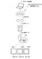
ここで、第1実施形態の特徴について説明する。図2に示すように、ユーザが認証データの追加、削除又は変更を行う際に、端末機11から矢印Y1で示すように、ID=「user1」,PW=「aaa」の認証データを認証サーバ15Aへ送信し、認証サーバ15Aがその認証データをDB15aに一時的にキャッシュする。このキャッシュ後、ユーザが端末機11から認証データの変更等をリクエストしてきた場合、認証サーバ15Aは、ユーザからの認証データと、DB15aにキャッシュされた認証データと比較し、一致すればOK、不一致でNGとする認証を行う。この認証結果のOK/NG(OK又はNG)を矢印Y2で示すように、端末機11へ応答する。 Here, the features of the first embodiment will be described. As shown in FIG. 2, when the user adds, deletes, or changes the authentication data, the authentication data of ID=“user1” and PW=“aaa” is input from the terminal 11 to the authentication server. 15A, and theauthentication server 15A temporarily caches the authentication data in theDB 15a. After the cache, when the user requests to change the authentication data from the terminal device 11, theauthentication server 15A compares the authentication data from the user with the authentication data cached in theDB 15a, and if they match, OK, no match. Authenticate as NG. The authentication result OK/NG (OK or NG) is responded to the terminal device 11 as indicated by an arrow Y2.

つまり、ユーザの認証データの変更等のリクエスト時に、認証サーバ15Aに送信されてきた認証データを、DB15aに認証用のものとして一時的にキャッシュし、このキャッシュされた認証データで、FPGA装置16Aの代わりに認証を行う。通常は、認証データ変更等のリクエストの都度、FPGA装置16Aの認証データに対応する全ての電子回路(回路ともいう)を書き換える必要がある。しかし、本実施形態では、一時的にキャッシュされた認証データで認証を行い、この一時的なキャッシュ時にはFPGA装置16Aの回路の書き換えは行わないので、FPGA装置16Aのリクエストに応じた回路の頻繁な書き換えを防止可能となっている。 That is, the authentication data transmitted to theauthentication server 15A at the time of a request for changing the authentication data of the user is temporarily cached in theDB 15a for authentication, and the cached authentication data of theFPGA device 16A is used. Authenticate instead. Normally, it is necessary to rewrite all electronic circuits (also referred to as circuits) corresponding to the authentication data of theFPGA device 16A each time a request for changing the authentication data is made. However, in the present embodiment, the authentication is performed with the temporarily cached authentication data, and the circuit of theFPGA device 16A is not rewritten during this temporary cache, so that the circuit frequently responds to the request of theFPGA device 16A. Rewriting can be prevented.

次に、認証サーバ15Aは、上記キャッシュされた全ての認証データを、ユーザからのアクセスが少ない夜間等の所定時刻に、矢印Y3に示すように、バッチ処理でFPGA装置16Aへ送信する。バッチ処理は、予め定められた時刻時や、キャッシュされたデータが例えば100件を超える等のイベント発生時に行われるようになっている。FPGA装置16Aは、その送信された認証データに対応するように回路を書き換える。この書き換えられた回路の認証データは、DB15aから削除される。FPGA装置16Aへの書き換え後は、FPGA装置16Aで認証データの認証を行い、この結果のOK/NGを矢印Y4,Y2で示すように、認証サーバ15Aを介して端末機11へ返信する。 Next, theauthentication server 15A transmits all the cached authentication data to theFPGA device 16A by batch processing at a predetermined time such as nighttime when the access from the user is small, as indicated by an arrow Y3. The batch process is performed at a predetermined time or when an event occurs, for example, when the number of cached data exceeds 100. TheFPGA device 16A rewrites the circuit so as to correspond to the transmitted authentication data. The rewritten authentication data of the circuit is deleted from theDB 15a. After rewriting to theFPGA device 16A, theFPGA device 16A authenticates the authentication data, and the OK/NG result is returned to the terminal device 11 via theauthentication server 15A as indicated by arrows Y4 and Y2.

このようにバッチ処理で、DB15aにキャッシュされた全ての認証データを纏めてFPGA装置16Aへ転送して反映することで、ユーザ当たりの更新オーバーヘッドの時間を削ることが可能となっている。また、認証データを纏めて更新できるので、認証データが1ユーザでも実行される更新時の通信一時中断の回数が少なくて済む。つまり、ユーザへの提供サービスの中断を抑制することが可能となっている。 In this way, by batch processing, all the authentication data cached in theDB 15a are collectively transferred to theFPGA device 16A and reflected, whereby it is possible to reduce the update overhead time per user. Further, since the authentication data can be collectively updated, the number of times of temporary interruption of communication at the time of updating the authentication data by one user can be small. That is, it is possible to prevent interruption of the service provided to the user.

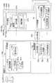
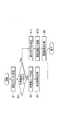
次に、認証サーバ15A及びFPGA装置16Aの構成を説明する。図3に示すように、認証サーバ15Aは、AP認証部21及び認証制御部22を備えて構成されている。AP認証部21は、上述したキャッシュ用DB15aの他に、認証連携部21aと、ユーザ管理部21bと、ユーザリスト用DB21cとを備えて構成されている。 Next, the configurations of theauthentication server 15A and theFPGA device 16A will be described. As shown in FIG. 3, theauthentication server 15A includes anAP authentication unit 21 and anauthentication control unit 22. TheAP authentication unit 21 includes anauthentication cooperation unit 21a, auser management unit 21b, and auser list DB 21c, in addition to thecache DB 15a described above.

認証制御部22は、認証サーバ15Aの外部のHDL(Hardware Description Language:ハードウェア記述言語)用DB22bが接続されたHDL生成部22aと、コンフィグデータ生成部22cと、FPGA再起動部22dとを備えて構成されている。 Theauthentication control unit 22 includes anHDL generation unit 22a to which an HDL (Hardware Description Language)DB 22b outside theauthentication server 15A is connected, a configurationdata generation unit 22c, and anFPGA restart unit 22d. Is configured.

FPGA装置16Aは、FPGA25と、このFPGA25と一対で設けられるハード制御部26とを備えて構成されている。FPGA25は、受付回路27a及び認証回路27bを有する認証部27を備えている。ハード制御部26は、FPGA書換部26aと、コンフィグデータ用DB26bと、FPGA電源部26cとを備えて構成されている。 TheFPGA device 16A is configured to include anFPGA 25 and ahardware control unit 26 provided as a pair with theFPGA 25. TheFPGA 25 includes anauthentication unit 27 having areception circuit 27a and anauthentication circuit 27b. Thehardware control unit 26 includes anFPGA rewriting unit 26a, aconfiguration data DB 26b, and an FPGApower supply unit 26c.

ユーザリスト用DB21cは、図4に示すユーザリストテーブルT1(ユーザリストT1ともいう)を保持している。このユーザリストT1には、例えば、ユーザ1のIDとして「user1」、IDの登録の状態として「登録済み」の情報が書き込まれている。更に、ユーザ2のID=「user2」、状態=「登録済み」の情報が書き込まれ、ユーザ3のID=「user3」、状態=「削除済み」の情報が書き込まれている。 Theuser list DB 21c holds a user list table T1 (also called a user list T1) shown in FIG. In the user list T1, for example, information of "user1" as the ID of theuser 1 and "registered" as the ID registration state is written. Further, the information of theuser 2 ID=“user2”, the state=“registered” is written, and the information of theuser 3 ID=“user3”, the state=“deleted” is written.

キャッシュ用DB15aは、図5に示すキャッシュテーブルT2(キャッシュT2ともいう)をキャッシュしている。このキャッシュT2には、例えば、ユーザ1のIDとして「user1」、PWとして「aaa」の情報が書き込まれている。更に、ユーザ2のID=「user2」、PW=「bbb」の情報が書き込まれ、ユーザ3のID=「user3」、PW=「ccc」の情報が書き込まれている。 Thecache DB 15a caches the cache table T2 (also referred to as cache T2) shown in FIG. In the cache T2, for example, information of "user1" as the ID of theuser 1 and "aaa" as the PW is written. Further, the information of theuser 2 ID=“user2” and PW=“bbb” is written, and the information of theuser 3 ID=“user3” and PW=“ccc” is written.

なお、上述したユーザリスト用DB21c、HDL用DB22b、コンフィグデータ用DB26bを、単に、DB21c、DB22b、DB26bとも称す。 Theuser list DB 21c, theHDL DB 22b, and theconfiguration data DB 26b described above are also simply referred to asDB 21c,DB 22b, andDB 26b.

<第1実施形態の認証構成>
図3に示す認証連携部21aは、APサーバ14を経由した端末機11(図1)からの認証リクエストを認証データと共に受信する。ユーザ管理部21bは、その受信された認証データを、DB21cに保存されたユーザリストT1から検索する。この結果、例えば、ユーザ3の認証データが受信された場合、ユーザリストT1には、ユーザ3のID=「user3」(図4)が「削除済み」となってユーザ3のIDが無いので、ユーザ管理部21bはユーザ3の登録が無いと判定する。この判定結果、認証連携部21aは、ユーザ3の端末機11への応答を行わない、又は、未登録案内をAPサーバ14を介してその端末機11へ応答(返信)する。
<Authentication configuration of the first embodiment>
Theauthentication cooperation unit 21a shown in FIG. 3 receives the authentication request from the terminal 11 (FIG. 1) via the AP server 14 together with the authentication data. Theuser management unit 21b searches the received authentication data from the user list T1 stored in theDB 21c. As a result, for example, when the authentication data of theuser 3 is received, the ID of theuser 3=“user3” (FIG. 4) is “deleted” and there is nouser 3 ID in the user list T1. Theuser management unit 21b determines that theuser 3 is not registered. As a result of this determination, theauthentication cooperation unit 21a does not respond to the terminal device 11 of theuser 3, or responds (replies) to the terminal device 11 via the AP server 14 with unregistered guidance.

一方、ユーザリストT1にユーザ3の認証データが登録済みであれば、ユーザ管理部21bがDB15aのキャッシュT2を検索する。この検索結果、例えば、キャッシュテーブルT2(図5)に示すように、ユーザ3のID=「user3」及びPW=「ccc」の認証データがキャッシュされていれば、ユーザ管理部21bは、そのキャッシュされた認証データと、認証連携部21aで受信された認証データとを比較し、一致すればOK、不一致でNGとする認証を行う。その認証結果のOK/NG(OK又はNG)を、認証連携部21aが、APサーバ14を介してユーザ3の端末機11へ返信する。 On the other hand, if the authentication data of theuser 3 is already registered in the user list T1, theuser management unit 21b searches the cache T2 of theDB 15a. As a result of this search, for example, as shown in the cache table T2 (FIG. 5), if the authentication data of the ID=“user3” and PW=“ccc” of theuser 3 is cached, theuser management unit 21b determines that cache The authentication data thus obtained is compared with the authentication data received by theauthentication cooperation unit 21a, and if they match, authentication is made OK, and if they do not match, authentication is made NG. Theauthentication cooperation unit 21 a returns OK/NG (OK or NG) of the authentication result to the terminal device 11 of theuser 3 via the AP server 14.

一方、キャッシュT2に、ユーザ3の認証データがキャッシュされていなければ、認証連携部21aが、ユーザ3の認証データを、FPGA装置16Aの受付回路27aへ送信する。受付回路27aがユーザ3の認証データを受け付けると、認証回路27bが、その受け付けられたユーザ3の認証データと、FPGA25に電子回路として形成されているユーザ3の認証データとを、アンドを取って認証する。この認証結果(OK/NG)は、受付回路27aを介して認証連携部21aへ返信され、更に、認証連携部21aからAPサーバ14を介してユーザ3の端末機11へ返信(応答)される。 On the other hand, if the authentication data of theuser 3 is not cached in the cache T2, theauthentication cooperation unit 21a transmits the authentication data of theuser 3 to thereception circuit 27a of theFPGA device 16A. When thereception circuit 27a receives the authentication data of theuser 3, theauthentication circuit 27b takes the AND of the received authentication data of theuser 3 and the authentication data of theuser 3 formed as an electronic circuit in theFPGA 25. Certify. This authentication result (OK/NG) is returned to theauthentication cooperation unit 21a via thereception circuit 27a, and is further returned (response) from theauthentication cooperation unit 21a to the terminal device 11 of theuser 3 via the AP server 14. ..

<第1実施形態のユーザ追加構成>
図3に示す認証連携部21aは、端末機11からのユーザ追加リクエストと共に認証データを受信する。ユーザ管理部21bは、その受信された認証データのIDを、DB21cに保存されたユーザリストT1から検索する。この結果、例えば、追加対象ユーザ4のIDが登録済みであれば、ユーザ管理部21bは、ユーザ4が登録済みであることを認証連携部21aへ通知し、認証連携部21aが、ユーザ4のIDが登録済みであることを、その端末機11へ返信(応答)する。
<User Addition Configuration of First Embodiment>
Theauthentication cooperation unit 21a illustrated in FIG. 3 receives the authentication data together with the user addition request from the terminal device 11. Theuser management unit 21b searches the user list T1 stored in theDB 21c for the ID of the received authentication data. As a result, for example, if the ID of the addition target user 4 has been registered, theuser management unit 21b notifies theauthentication cooperation unit 21a that the user 4 has been registered, and theauthentication cooperation unit 21a notifies the user 4 of the addition. It returns (responds) to the terminal 11 that the ID has been registered.

一方、ユーザリストT1にユーザ4のID登録が無ければ、ユーザ管理部21bは、DB15aのキャッシュT2に、追加対象ユーザ4のID及びPWの認証データをキャッシュする。更に、ユーザ管理部21bは、DB21cのユーザリストT1に、追加対象ユーザ4のIDを追加して更新する。上記キャッシュされた認証データは、認証制御部22の制御によって、例えば夜間等の所定の時刻に、バッチ処理でFPGA装置16Aに転送される。なお、バッチ処理を行うタイミングを、バッチタイミングと称す。 On the other hand, if there is no ID registration of the user 4 in the user list T1, theuser management unit 21b caches the ID of the addition target user 4 and the authentication data of the PW in the cache T2 of theDB 15a. Further, theuser management unit 21b adds the ID of the addition target user 4 to the user list T1 of theDB 21c and updates it. The cached authentication data is transferred to theFPGA device 16A by batch processing at a predetermined time such as night under the control of theauthentication control unit 22. The timing of performing the batch process is referred to as the batch timing.

認証連携部21aは、上記ユーザリストT1への認証データのIDの追加後、バッチタイミングとなった時点で、通信サービスを一時中断してユーザからのリクエストを受け付けないようにする。この後、認証連携部21aは、追加対象ユーザ4の認証データをHDL生成部22aに出力する。HDL生成部22aは、HDL用DB22bから現在保持されているHDL(ハードウェア記述言語)によるユーザの認証データを取得する。このHDLによるユーザの認証データをHDLデータと称す。 After adding the ID of the authentication data to the user list T1 described above, theauthentication cooperation unit 21a suspends the communication service at the batch timing so as not to accept the request from the user. After that, theauthentication cooperation unit 21a outputs the authentication data of the addition target user 4 to theHDL generation unit 22a. TheHDL generation unit 22a acquires user authentication data in HDL (hardware description language) currently held from theHDL DB 22b. User authentication data by this HDL is called HDL data.

HDL生成部22aは、その取得したHDLデータに、追加対象ユーザ4の認証データを追加して更新を行い、この更新されたHDLデータを生成すると共に、生成HDLデータをDB22bに上書きする。HDL用DB22bは、不正なアクセスを防止のため認証サーバ15Aの外部に配置されており、FPGA25に回路で実現される全ユーザの認証データのHDLデータを保持している。なお、DB22bを、認証サーバ15A内に配備することも可能である。 TheHDL generating unit 22a adds the authentication data of the addition target user 4 to the acquired HDL data and updates the generated HDL data, and at the same time, overwrites the generated HDL data in theDB 22b. TheHDL DB 22b is arranged outside theauthentication server 15A to prevent unauthorized access, and holds the HDL data of all user authentication data realized by a circuit in theFPGA 25. TheDB 22b can be installed in theauthentication server 15A.

コンフィグデータ生成部22cは、HDL生成部22aで生成されたHDLデータに基づきコンフィグデータを生成し、このコンフィグデータをFPGA装置16AのFPGA書換部26aへ送信する。FPGA書換部26aは、その送信されてきたコンフィグデータに応じて、DB26bに保持されたコンフィグデータを書き換える。これによって、追加対象ユーザ4の認証データが反映されたコンフィグデータがDB26bに上書きされて保持される。 The configurationdata generation unit 22c generates configuration data based on the HDL data generated by theHDL generation unit 22a, and sends this configuration data to theFPGA rewriting unit 26a of theFPGA device 16A. TheFPGA rewriting unit 26a rewrites the configuration data held in theDB 26b according to the transmitted configuration data. Thereby, the configuration data reflecting the authentication data of the addition target user 4 is overwritten and held in theDB 26b.

上記コンフィグデータの書き換え後、FPGA電源部26cがFPGA25を再起動又は自動再起動することにより、FPGA25の回路が、その書き換え後のコンフィグデータに対応する回路に書き換わる。この回路の書換情報は、FPGA書換部26aから認証サーバ15Aのコンフィグデータ生成部22c及びHDL生成部22aを経由し、更に認証連携部21aを介してユーザ管理部21bへ通知される。通知を受けたユーザ管理部21bは、その回路の書換情報に対応するDB15aにキャッシュされた認証データを削除する。この削除後、認証連携部21aは、ユーザ4の端末機11へ認証データが追加されたことを返信する。 After rewriting the configuration data, the FPGApower supply unit 26c restarts or automatically restarts theFPGA 25, so that the circuit of theFPGA 25 is rewritten to the circuit corresponding to the rewritten configuration data. The rewriting information of this circuit is notified from theFPGA rewriting unit 26a to theuser management unit 21b via the configurationdata generation unit 22c and theHDL generation unit 22a of theauthentication server 15A and further via theauthentication cooperation unit 21a. Upon receiving the notification, theuser management unit 21b deletes the authentication data cached in theDB 15a corresponding to the rewriting information of the circuit. After this deletion, theauthentication cooperation unit 21a replies to the terminal 11 of the user 4 that the authentication data has been added.

<第1実施形態のユーザ削除構成>
図3に示す認証連携部21aは、端末機11からのユーザ削除リクエストと共に認証データを受信する。ユーザ管理部21bは、その受信された認証データのIDをユーザリストT1から検索する。この結果、例えば、削除対象ユーザ3のIDの登録が無ければ削除の必要が無いので、ユーザ管理部21bは、ユーザ3のIDが未登録ユーザであることを認証連携部21aへ通知する。この通知に応じて認証連携部21aは、ユーザ3の端末機11への応答を行わない、又は、削除対象ユーザ3のIDが未登録であることを、その端末機11へ応答(返信)する。
<User Deletion Configuration of First Embodiment>
Theauthentication cooperation unit 21a shown in FIG. 3 receives the authentication data together with the user deletion request from the terminal device 11. Theuser management unit 21b searches the user list T1 for the ID of the received authentication data. As a result, for example, if there is no registration of the ID of theuser 3 to be deleted, there is no need to delete it, so theuser management unit 21b notifies theauthentication cooperation unit 21a that the ID of theuser 3 is an unregistered user. In response to this notification, theauthentication cooperation unit 21a does not respond to the terminal device 11 of theuser 3 or responds (replies) to the terminal device 11 that the ID of thedeletion target user 3 is not registered. ..

一方、ユーザ3のIDの登録が有れば、PW認証を行う。この認証がOKであれば、ユーザ管理部21bは、DB21cのユーザリストT1に登録された削除対象のユーザ3のIDを削除し、この削除されたユーザ3のIDが存在しないユーザリストT1に更新する。更に、ユーザ管理部21bは、DB15aのキャッシュT2にキャッシュされた削除対象ユーザ3のID及びPWの認証データが有れば削除して更新する。 On the other hand, if the ID of theuser 3 is registered, PW authentication is performed. If this authentication is OK, theuser management unit 21b deletes the ID of theuser 3 to be deleted registered in the user list T1 of theDB 21c, and updates the user list T1 in which the ID of the deleteduser 3 does not exist. To do. Furthermore, theuser management unit 21b deletes and updates the ID of thedeletion target user 3 and the authentication data of the PW cached in the cache T2 of theDB 15a, if any.

認証連携部21aは、上記ユーザリストT1からのユーザ3のIDの削除後に、或いは、削除対象ユーザ3の認証データがキャッシュされていない場合に、バッチタイミングとなった時点で、通信サービスを一時中断する。この後、認証連携部21aは、上記ユーザ3の認証データ削除が反映されたキャッシュ中の他のユーザの認証データを、HDL生成部22aに出力する。HDL生成部22aは、DB22bから現在保持中のHDLデータを取得する。HDL生成部22aは、その取得したHDLデータを、上記削除が反映された他のユーザの認証データに基づき更新し、この更新されたHDLデータをコンフィグデータ生成部22cへ出力すると共に、DB22bに上書きする。 Theauthentication cooperation unit 21a temporarily suspends the communication service after the deletion of the ID of theuser 3 from the user list T1 or when the authentication data of thedeletion target user 3 is not cached and at the batch timing. To do. After that, theauthentication cooperation unit 21a outputs the authentication data of the other user in the cache, in which the deletion of the authentication data of theuser 3 is reflected, to theHDL generation unit 22a. TheHDL generation unit 22a acquires the currently held HDL data from theDB 22b. TheHDL generating unit 22a updates the acquired HDL data based on the authentication data of the other user in which the deletion is reflected, outputs the updated HDL data to the configurationdata generating unit 22c, and overwrites theDB 22b. To do.

コンフィグデータ生成部22cは、上記更新されたHDLデータに基づきコンフィグデータを生成して送信する。FPGA書換部26aは、その送信されてきたコンフィグデータに応じてDB26bに保持されたコンフィグデータを書き換える(上書きする)。これによって、削除対象ユーザ3の認証データの削除が反映されたコンフィグデータがDB26bに上書きされて保持される。 Theconfiguration data generator 22c generates and transmits configuration data based on the updated HDL data. TheFPGA rewriting unit 26a rewrites (overwrites) the configuration data held in theDB 26b according to the transmitted configuration data. As a result, the configuration data reflecting the deletion of the authentication data of thedeletion target user 3 is overwritten and held in theDB 26b.

上記コンフィグデータの書き換え後(上書き後)、FPGA電源部26cがFPGA25を再起動又は自動再起動することにより、FPGA25の回路が、その書き換え後のコンフィグデータに対応する回路に書き換えられる。この回路の書換情報が、FPGA書換部26aから認証サーバ15Aのコンフィグデータ生成部22c及びHDL生成部22aを経由し、更に認証連携部21aを介してユーザ管理部21bへ通知されると、ユーザ管理部21bが、その回路の書換情報に対応するDB15aにキャッシュされた認証データを削除する。この削除後、認証連携部21aは、ユーザ3の端末機11へ認証データが削除されたことを返信する。 After the rewriting of the configuration data (after overwriting), the FPGApower supply unit 26c restarts or automatically restarts theFPGA 25, whereby the circuit of theFPGA 25 is rewritten to the circuit corresponding to the rewritten configuration data. When the rewriting information of this circuit is notified from theFPGA rewriting unit 26a to theuser management unit 21b via the configurationdata generation unit 22c and theHDL generation unit 22a of theauthentication server 15A and further via theauthentication cooperation unit 21a, the user management is performed. Theunit 21b deletes the authentication data cached in theDB 15a corresponding to the rewrite information of the circuit. After this deletion, theauthentication cooperation unit 21a returns to the terminal 11 of theuser 3 that the authentication data has been deleted.

<第1実施形態のユーザ認証データ変更構成>
図3に示す認証連携部21aは、端末機11からのユーザ認証データ変更リクエストと共に認証データを受信する。ユーザ管理部21bは、その受信された認証データのIDをユーザリストT1から検索する。この結果、例えば、変更対象ユーザ3のIDの登録が無ければ、ユーザ管理部21bは、未登録ユーザであることを認証連携部21aへ通知する。この通知に応じて認証連携部21aは、ユーザ3の端末機11への応答を行わない、又は、ユーザ3のIDが未登録であることを、その端末機11へ返信する。
<User Authentication Data Change Configuration of First Embodiment>
Theauthentication cooperation unit 21a shown in FIG. 3 receives the authentication data together with the user authentication data change request from the terminal 11. Theuser management unit 21b searches the user list T1 for the ID of the received authentication data. As a result, for example, if the ID of thechange target user 3 is not registered, theuser management unit 21b notifies theauthentication cooperation unit 21a that the user is an unregistered user. In response to this notification, theauthentication cooperation part 21a does not respond to the terminal device 11 of theuser 3 or returns to the terminal device 11 that the ID of theuser 3 is not registered.

一方、変更対象ユーザ3のIDの登録が有れば、PW認証を行う。この認証がOKであれば、ユーザ管理部21bは、DB15aのキャッシュT2に変更対象ユーザ3のID及びPWの認証データがキャッシュされているか否かを判定する。この結果、キャッシュされていれば、ユーザ管理部21bは、キャッシュされた変更対象ユーザ3の認証データを変更する。一方、キャッシュされていなければ、DB15aに、端末機11から受信した変更対象ユーザ3のID及びPWの認証データを追加キャッシュする。 On the other hand, if the ID of thechange target user 3 is registered, PW authentication is performed. If the authentication is OK, theuser management unit 21b determines whether the cache T2 of theDB 15a caches the ID of thechange target user 3 and the authentication data of the PW. As a result, if cached, theuser management unit 21b changes the cached authentication data of thechange target user 3. On the other hand, if it is not cached, the ID of thechange target user 3 and the authentication data of the PW received from the terminal 11 are additionally cached in theDB 15a.

認証連携部21aは、上記キャッシュされた認証データの変更後、又は上記認証データの追加キャッシュ後、バッチタイミングとなった時点で、通信サービスを一時中断する。この後、認証連携部21aは、変更対象ユーザ3のキャッシュ中の認証データをHDL生成部22aに出力する。HDL生成部22aは、DB22bから現在保持中のHDLデータを取得する。この取得したHDLデータを、上記キャッシュ中の認証データに基づき更新し、この更新されたHDLデータを生成すると共に、生成HDLデータをDB22bに上書きする。 Theauthentication cooperation unit 21a suspends the communication service at a batch timing after the cached authentication data is changed or after the additional authentication data is cached. After that, theauthentication cooperation unit 21a outputs the authentication data in the cache of thechange target user 3 to theHDL generation unit 22a. TheHDL generation unit 22a acquires the currently held HDL data from theDB 22b. The acquired HDL data is updated based on the authentication data in the cache, the updated HDL data is generated, and the generated HDL data is overwritten in theDB 22b.

コンフィグデータ生成部22cは、上記生成されたHDLデータに基づきコンフィグデータを生成してFPGA書換部26aへ送信する。FPGA書換部26aは、その送信されてきたコンフィグデータに応じてDB26bに保持されたコンフィグデータを上書きして書き換える。これによって、更新対象ユーザ3の認証データの更新が反映されたコンフィグデータがDB26bに保持される。 The configurationdata generation unit 22c generates configuration data based on the generated HDL data and transmits it to theFPGA rewriting unit 26a. TheFPGA rewriting unit 26a overwrites and rewrites the configuration data held in theDB 26b according to the transmitted configuration data. Thereby, the configuration data reflecting the update of the authentication data of theupdate target user 3 is held in theDB 26b.

上記コンフィグデータの書き換え後(上書き後)、FPGA電源部26cがFPGA25を再起動又は自動再起動することにより、FPGA25の回路が、その書き換え後のコンフィグデータに対応する回路に書き換えられる。この回路の書換情報が、FPGA書換部26aから認証サーバ15Aのコンフィグデータ生成部22c及びHDL生成部22aを経由し、更に認証連携部21aを介してユーザ管理部21bへ通知されると、ユーザ管理部21bが、その回路の書換情報に対応するDB15aにキャッシュされた認証データを削除する。 After the rewriting of the configuration data (after overwriting), the FPGApower supply unit 26c restarts or automatically restarts theFPGA 25, whereby the circuit of theFPGA 25 is rewritten to the circuit corresponding to the rewritten configuration data. When the rewriting information of this circuit is notified from theFPGA rewriting unit 26a to theuser management unit 21b via the configurationdata generation unit 22c and theHDL generation unit 22a of theauthentication server 15A and further via theauthentication cooperation unit 21a, the user management is performed. Theunit 21b deletes the authentication data cached in theDB 15a corresponding to the rewrite information of the circuit.

このキャッシュ削除後、認証データの変更がPWのみの変更であれば、認証連携部21aが、ユーザ3の端末機11へPWが変更されたことを返信する。一方、認証データの変更がIDの変更であれば、ユーザ管理部21bが、上記キャッシュ削除後、DB21cのユーザリストT1において、未だ変更されていない変更対象ユーザ3のIDを変更して更新する。このIDの更新も、ユーザ3の端末機11へ返信される。 After the cache is deleted, if the change of the authentication data is only the PW, theauthentication cooperation unit 21a replies to the terminal 11 of theuser 3 that the PW has been changed. On the other hand, if the change of the authentication data is the change of the ID, theuser management unit 21b, after deleting the cache, changes and updates the ID of thechange target user 3 in the user list T1 of theDB 21c that has not been changed. The update of this ID is also returned to the terminal device 11 of theuser 3.

<第1実施形態の認証動作>
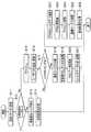
次に、認証システム10Aによるユーザの認証データの認証動作を、図6に示すフローチャートを参照して説明する。
前提条件として、図1に示す例えばユーザ1の端末機11からインターネット12及び社内NW13を介してAPサーバ14を経由し認証サーバ15Aへ、ユーザ1の認証リクエストが、認証データとしてのID=「user1」及びPW=「aaa」と共に送信されたとする。
<Authentication operation of the first embodiment>
Next, the authentication operation of the authentication data of the user by the authentication system 10A will be described with reference to the flowchart shown in FIG.
As a precondition, for example, the authentication request of theuser 1 is sent from the terminal 11 of theuser 1 shown in FIG. 1 to theauthentication server 15A via theInternet 12 and the in-house NW 13 and the AP server 14 to theauthentication server 15A. , And PW=“aaa”.

図6に示すステップS1において、認証サーバ15A(図3)の認証連携部21aが、端末機11からのユーザ1の認証リクエストをID及びPWと共に受信する。ステップS2において、ユーザ管理部21bは、受信されたユーザ1のIDが、DB21cに保存されたユーザリストT1に登録済みか否かを判定する。この結果、登録無し(No)の場合、ステップS3において、ユーザ管理部21bは未登録ユーザ対応の処理を行う。即ち、ユーザ1のIDの未登録案内を作成する。ステップS4において、認証連携部21aが、対応結果としての未登録案内をAPサーバ14を介してユーザ1の端末機11へ応答(返信)する。 In step S1 shown in FIG. 6, theauthentication cooperation unit 21a of theauthentication server 15A (FIG. 3) receives the authentication request of theuser 1 from the terminal 11 together with the ID and PW. In step S2, theuser management unit 21b determines whether the received ID of theuser 1 has been registered in the user list T1 stored in theDB 21c. As a result, if there is no registration (No), theuser management unit 21b performs a process corresponding to an unregistered user in step S3. That is, the unregistered guide of the ID of theuser 1 is created. In step S4, theauthentication cooperation unit 21a responds (replies) to the terminal device 11 of theuser 1 via the AP server 14 with the unregistered guide as the correspondence result.

一方、上記ステップS2において、ユーザリストT1にユーザ1の認証データが登録済み(Yes)であれば、ステップS5において、ユーザ管理部21bが、DB15a(DB15aのキャッシュT2)にユーザ1のID及びPWがキャッシュされているか否かを判定する。この結果、キャッシュされ、且つ追加フラグが付与されていれば(Yes)、ステップS6において、ユーザ管理部21bがキャッシュされたID及びPWと、上記受信されたID及びPWとを比較し、一致すればOK、不一致でNGとする認証を行う。このOK/NGの認証結果が、ステップS8において、認証連携部21aからユーザ1の端末機11へ応答される。 On the other hand, if the authentication data of theuser 1 has been registered in the user list T1 in step S2 (Yes), theuser management unit 21b stores the ID and PW of theuser 1 in theDB 15a (cache T2 of theDB 15a) in step S5. Is cached. As a result, if it is cached and the additional flag is added (Yes), in step S6, theuser management unit 21b compares the cached ID and PW with the received ID and PW, and finds a match. If it is OK, it will be authenticated as NG if it does not match. The authentication result of this OK/NG is returned to the terminal 11 of theuser 1 from theauthentication cooperation unit 21a in step S8.

一方、上記ステップS5において、ユーザ1のID及びPWがキャッシュされていなければ(No)、ステップS7において、認証連携部21aが、ユーザ1のID及びPWを、FPGA装置16Aの受付回路27aへ送信し、受付回路27aが次のように認証を行う。即ち、認証回路27bが、受け付けたユーザ1のID及びPWと、FPGA25に電子回路として形成されているユーザ1のID及びPWとを、アンドを取って認証する。このOK/NGの認証結果は、ステップS8において、ユーザ1の端末機11へ応答される。 On the other hand, if the ID and PW of theuser 1 are not cached in step S5 (No), theauthentication cooperation unit 21a transmits the ID and PW of theuser 1 to thereception circuit 27a of theFPGA device 16A in step S7. Then, theacceptance circuit 27a authenticates as follows. That is, theauthentication circuit 27b performs AND authentication on the received ID and PW of theuser 1 and the ID and PW of theuser 1 formed as an electronic circuit in theFPGA 25. The OK/NG authentication result is returned to the terminal 11 of theuser 1 in step S8.

<第1実施形態のユーザ追加動作>
次に、認証システム10Aによるユーザの認証データの追加動作を、図7に示すフローチャートを参照して説明する。
前提条件として、図1に示す例えばユーザ4の端末機11から認証サーバ15Aへ、ユーザ4の追加リクエストが、認証データとしてのID=「user4」及びPW=「ddd」と共に送信されたとする。
<User addition operation of the first embodiment>
Next, the operation of adding the user authentication data by the authentication system 10A will be described with reference to the flowchart shown in FIG.
As a precondition, it is assumed that the addition request of the user 4 is sent from the terminal 11 of the user 4 shown in FIG. 1 to theauthentication server 15A with ID=“user4” and PW=“ddd” as the authentication data.

図7に示すステップS11において、認証サーバ15Aの認証連携部21aが、端末機11からのユーザ4の追加リクエストをID及びPWと共に受信する。ステップS12において、ユーザ管理部21bは、受信されたユーザ4のIDが、ユーザリストT1に登録済みか否かを判定する。この結果、登録有り(Yes)の場合、ステップS13において、ユーザ管理部21bは登録済みユーザ対応の処理を行う。即ち、ユーザ4のIDが登録済みであることを案内する登録有りの案内を作成する。ステップS14において、認証連携部21aが、対応結果としての登録有りの案内をユーザ4の端末機11へ応答する。 In step S11 shown in FIG. 7, theauthentication cooperation unit 21a of theauthentication server 15A receives the addition request of the user 4 from the terminal 11 together with the ID and PW. In step S12, theuser management unit 21b determines whether or not the received ID of the user 4 has been registered in the user list T1. As a result, in the case of registration (Yes), theuser management unit 21b performs a process corresponding to the registered user in step S13. That is, a guide with registration indicating that the ID of the user 4 is already registered is created. In step S14, theauthentication cooperation unit 21a responds to the terminal 11 of the user 4 with a registration-provided guidance as a correspondence result.

一方、上記ステップS12において、ユーザリストT1にユーザ4のID登録が無ければ(No)、ステップS15において、ユーザ管理部21bは、DB15aに、上記受信したユーザ4のID及びPWをキャッシュする。更に、ステップS16において、ユーザ管理部21bは、ユーザリストT1に、ユーザ4のIDを追加して更新する。 On the other hand, if there is no ID registration of the user 4 in the user list T1 in step S12 (No), theuser management unit 21b caches the received ID and PW of the user 4 in theDB 15a in step S15. Further, in step S16, theuser management unit 21b adds the ID of the user 4 to the user list T1 and updates it.

ステップS17において、認証連携部21aは、上記ステップS16のID追加後、バッチタイミングとなったか否かを判定し、バッチタイミングとなった時(Yes)に、ステップS18において、通信サービスを中断する。この中断によって、他のユーザからのリクエストを受け付けないようになる。この後、認証連携部21aは、ユーザ4のID及びPWをHDL生成部22aに出力する。 In step S17, theauthentication cooperation unit 21a determines whether or not the batch timing has come after the ID addition in step S16, and when the batch timing comes (Yes), the communication service is interrupted in step S18. Due to this interruption, requests from other users will not be accepted. After that, theauthentication cooperation unit 21a outputs the ID and PW of the user 4 to theHDL generation unit 22a.

ステップS19において、HDL生成部22aは、認証連携部21aからユーザ4のID及びPWを受信すると、DB22bに現在保持されている更新前のHDLデータ(HDLによるユーザのID及びPWのデータ)を取得する。この取得されたHDLデータには、追加対象のユーザ4のID及びPWは含まれていない。ステップS20において、HDL生成部22aは、その取得したHDLデータに、ユーザ4のID及びPWのデータを追加して更新を行う。この更新されたHDLデータをDB22bに上書きする。 In step S19, when theHDL generation unit 22a receives the ID and PW of the user 4 from theauthentication cooperation unit 21a, the HDL data before update (user ID and PW data by HDL) currently held in theDB 22b is acquired. To do. The acquired HDL data does not include the ID and PW of the user 4 to be added. In step S20, theHDL generating unit 22a adds the ID of the user 4 and the data of the PW to the acquired HDL data to update it. The updated HDL data is overwritten on theDB 22b.

次に、ステップS21において、コンフィグデータ生成部22cは、上記生成されたHDLデータに基づきコンフィグデータを生成し、このコンフィグデータをFPGA装置16AのFPGA書換部26aへ送信する。 Next, in step S21, the configurationdata generation unit 22c generates configuration data based on the generated HDL data and transmits this configuration data to theFPGA rewriting unit 26a of theFPGA device 16A.

ステップS22において、FPGA書換部26aは、その送信されてきたコンフィグデータに応じて、DB26bに保持されたコンフィグデータを上書きして書き換える。これによって、追加対象ユーザ4のID及びPWが反映されたコンフィグデータがDB26bに保持される。 In step S22, theFPGA rewriting unit 26a overwrites and rewrites the configuration data held in theDB 26b according to the transmitted configuration data. Thereby, the configuration data reflecting the ID and PW of the addition target user 4 is held in theDB 26b.

上記コンフィグデータの書き換え後、ステップS23において、FPGA電源部26cがFPGA25を再起動又は自動再起動する。これにより、FPGA25の回路が、その書き換え後のコンフィグデータに対応する回路に書き換わる。この回路の書換情報は、FPGA書換部26aから認証サーバ15Aのコンフィグデータ生成部22c及びHDL生成部22aを経由し、更に認証連携部21aを介してユーザ管理部21bへ通知される。 After rewriting the configuration data, the FPGApower supply unit 26c restarts or automatically restarts theFPGA 25 in step S23. As a result, the circuit of theFPGA 25 is rewritten to the circuit corresponding to the rewritten configuration data. The rewriting information of this circuit is notified from theFPGA rewriting unit 26a to theuser management unit 21b via the configurationdata generation unit 22c and theHDL generation unit 22a of theauthentication server 15A and further via theauthentication cooperation unit 21a.

その通知を受けたユーザ管理部21bは、その回路の書換情報に対応するDB15aにキャッシュされたID及びPWを削除する。この削除後、ステップS25において、認証連携部21aは端末機11へ提供する通信サービスを再開する。この再開後、ステップS26において、認証連携部21aは、端末機11へユーザ4のID及びPWが追加されたことを応答する。 Upon receiving the notification, theuser management unit 21b deletes the ID and PW cached in theDB 15a corresponding to the rewrite information of the circuit. After this deletion, in step S25, theauthentication cooperation unit 21a restarts the communication service provided to the terminal device 11. After this restart, in step S26, theauthentication cooperation part 21a responds to the addition of the ID and PW of the user 4 to the terminal device 11.

<第1実施形態のユーザ削除動作>
次に、認証システム10Aによるユーザの認証データの削除動作を、図8に示すフローチャートを参照して説明する。但し、図8において、図6及び図7と同一ステップには()内に同一ステップの符号を付し、その説明を適宜省略する。
前提条件として、図1に示す例えばユーザ1の端末機11から認証サーバ15Aへ、ユーザ1の削除リクエストが、認証データとしてのID=「user1」及びPW=「aaa」と共に送信されたとする。
<User deletion operation of the first embodiment>
Next, the operation of deleting the authentication data of the user by the authentication system 10A will be described with reference to the flowchart shown in FIG. However, in FIG. 8, the same steps as those in FIGS. 6 and 7 are denoted by the same reference numerals in parentheses, and the description thereof will be appropriately omitted.
As a precondition, it is assumed that a delete request foruser 1 is sent from terminal 11 ofuser 1 shown in FIG. 1 toauthentication server 15A with ID=“user1” and PW=“aaa” as authentication data.

図8に示すステップS31において、認証サーバ15Aの認証連携部21aが、端末機11からのユーザ1の削除リクエストをID及びPWと共に受信する。この後、上述したように、ステップS32(図6のS2)において、受信ユーザ1のIDがユーザリストT1に登録済みか否かが判定され、登録が無ければ(No)ステップS33(S3)において、未登録ユーザ対応の処理としてユーザ1のIDの未登録案内が作成される。ステップS34(S4)において、対応結果としての未登録案内がユーザ1の端末機11へ応答される。 In step S31 shown in FIG. 8, theauthentication cooperation part 21a of theauthentication server 15A receives the deletion request of theuser 1 from the terminal 11 together with the ID and PW. Thereafter, as described above, in step S32 (S2 in FIG. 6), it is determined whether or not the ID of the receivinguser 1 is already registered in the user list T1. If there is no registration (No), in step S33 (S3). As a process corresponding to the unregistered user, an unregistered guide of the ID of theuser 1 is created. In step S34 (S4), the unregistered guidance as a response result is returned to the terminal 11 of theuser 1.

一方、上記ステップS32において、ユーザ1のID登録が有れば(Yes)、ステップS32aにおいて、図6の認証処理でPW認証を行う。この認証がOKであれば、ステップS35において、ユーザ管理部21bは、ユーザリストT1に登録された削除対象のユーザ1のIDを削除し、この削除されたユーザ1のIDが存在しないユーザリストT1に更新する。この後、ステップS36(S5)において、DB15aにユーザ1のID及びPWがキャッシュされているか否かが判定される。この結果、キャッシュされていれば(Yes)、ステップS37において、ユーザ管理部21bが、DB15aにキャッシュされた削除対象ユーザ1の状態フラグを削除に変更する。一方、キャッシュされていなければ(No)、ステップS36aにおいて、削除対象ユーザ1のID及びPWを追加キャッシュすると共に、この状態フラグを削除とする。 On the other hand, if theuser 1's ID is registered in step S32 (Yes), PW authentication is performed in step S32a by the authentication process of FIG. If this authentication is OK, in step S35, theuser management unit 21b deletes the ID of thedeletion target user 1 registered in the user list T1, and the deleteduser 1 ID does not exist in the user list T1. To update. Then, in step S36 (S5), it is determined whether the ID and PW of theuser 1 are cached in theDB 15a. As a result, if cached (Yes), theuser management unit 21b changes the state flag of thedeletion target user 1 cached in theDB 15a to deletion in step S37. On the other hand, if it is not cached (No), in step S36a, the ID and PW of thedeletion target user 1 are additionally cached, and this status flag is deleted.

上記ステップS37又はS36aの処理後、認証連携部21aは、ステップS38(図7のS17)において、バッチタイミングとなった(Yes)時点で、ステップS39(S18)において、通信サービスを一時中断する。この後、認証連携部21aが、削除フラグが設定された上記ユーザ1のID及びPWの削除が反映されたキャッシュ中のID及びPWを、HDL生成部22aに出力する。 After the processing of step S37 or S36a, theauthentication cooperation unit 21a temporarily suspends the communication service in step S39 (S18) at the batch timing (Yes) in step S38 (S17 of FIG. 7). After that, theauthentication cooperation unit 21a outputs the ID and PW in the cache in which the deletion of the ID and PW of theuser 1 for which the deletion flag is set is reflected to theHDL generation unit 22a.

ステップS40(S19)において、HDL生成部22aが、DB22bから現在保持中のHDLデータを取得する。この取得したHDLデータを、ステップS41において、HDL生成部22aが、上記削除が反映された他のユーザのID及びPWに基づき更新し、この更新されたHDLデータを、コンフィグデータ生成部22cへ出力すると共にDB22bに上書きする。その更新されたHDLデータはユーザ1のID及びPWが存在しないデータとなる。 In step S40 (S19), theHDL generation unit 22a acquires the currently held HDL data from theDB 22b. In step S41, theHDL generation unit 22a updates the acquired HDL data based on the ID and PW of another user in which the deletion is reflected, and outputs the updated HDL data to the configurationdata generation unit 22c. And theDB 22b is overwritten. The updated HDL data is data in which theuser 1 ID and PW do not exist.

ステップS42において、コンフィグデータ生成部22cは、上記更新されたHDLデータに基づきコンフィグデータを生成してFPGA書換部26aへ送信する。ステップS43において、FPGA書換部26aは、その送信されてきたコンフィグデータに応じてDB26bに保持されたコンフィグデータを上書きして書き換える。この書き換えられたデータは、上記ユーザ1の削除が反映されたコンフィグデータとなる。 In step S42, the configurationdata generation unit 22c generates configuration data based on the updated HDL data and transmits it to theFPGA rewriting unit 26a. In step S43, theFPGA rewriting unit 26a overwrites and rewrites the configuration data held in theDB 26b according to the transmitted configuration data. The rewritten data becomes the config data in which the deletion of theuser 1 is reflected.

その書き換え後、ステップS44(S23)において、FPGA25が再起動又は自動再起動される。これにより、FPGA25の回路が、上記ユーザ1の削除が反映されたコンフィグデータに対応する回路に書き換えられる。この書き換え後、ステップS44aにおいて、キャッシュ中の削除フラグが付いたユーザ1のID及びPWを削除した後、ステップS45(S25)において、認証連携部21aが端末機11へ提供する通信サービスを再開する。この再開後、ステップS46において、認証連携部21aが、端末機11へユーザ1のID及びPWが削除されたことを応答する。 After the rewriting, in step S44 (S23), theFPGA 25 is restarted or automatically restarted. As a result, the circuit of theFPGA 25 is rewritten to the circuit corresponding to the configuration data in which the deletion of theuser 1 is reflected. After this rewriting, in step S44a, after deleting the ID and PW of theuser 1 with the deletion flag in the cache, in step S45 (S25), theauthentication cooperation unit 21a restarts the communication service provided to the terminal device 11. . After this resumption, in step S46, theauthentication cooperation unit 21a responds to the terminal device 11 that the ID and PW of theuser 1 have been deleted.

<第1実施形態のユーザ認証データ変更動作>
次に、認証システム10Aによるユーザの認証データの変更動作を、図9に示すフローチャートを参照して説明する。但し、図9において、図6及び図7と同一ステップには()内に同一ステップの符号を付し、その説明を適宜省略する。
前提条件として、図1に示す例えばユーザ1の端末機11から認証サーバ15Aへ、ユーザ1のPWの変更リクエストが、認証データとしてのID=「user1」、変更前のPW(変更前PW)=「aaa」及び変更後のPW(変更PW)=「aaa1」と共に送信されたとする。
<User authentication data changing operation of the first embodiment>
Next, the operation of changing the user authentication data by the authentication system 10A will be described with reference to the flowchart shown in FIG. However, in FIG. 9, the same steps as those in FIGS. 6 and 7 are denoted by the same reference numerals in parentheses, and the description thereof will be appropriately omitted.
As a precondition, for example, a request for changing the PW of theuser 1 is sent from the terminal 11 of theuser 1 to theauthentication server 15A shown in FIG. 1 when the ID as authentication data is “user1”, PW before change (PW before change)= It is assumed that the data is transmitted together with “aaa” and the changed PW (change PW)=“aaa1”.

図9に示すステップS51において、認証サーバ15Aの認証連携部21aが、端末機11からのユーザ1のPWの変更リクエストをID及びPWと共に受信する。この後、上述したように、ステップS52(図6のS2)において、受信ユーザ1のIDがユーザリストT1に登録済みか否かが判定され、この結果がNoの場合のステップS53(S3)において、未登録ユーザ対応の処理としてユーザ1のIDの未登録案内が作成される。ステップS54(S4)において、対応結果としての未登録案内がユーザ1の端末機11へ応答される。 In step S51 shown in FIG. 9, theauthentication cooperation part 21a of theauthentication server 15A receives the request for changing the PW of theuser 1 from the terminal 11 together with the ID and the PW. Thereafter, as described above, in step S52 (S2 in FIG. 6), it is determined whether or not the ID of the receivinguser 1 is already registered in the user list T1, and in the case where the result is No, in step S53 (S3). As a process corresponding to the unregistered user, an unregistered guide of the ID of theuser 1 is created. In step S54 (S4), the unregistered guidance as the response result is returned to the terminal 11 of theuser 1.

一方、上記ステップS52において、ユーザ1のID登録が有れば(Yes)、ステップS52aにおいて、図6の認証処理でPW認証を行う。この認証がOKであれば、ステップS55において、DB15aにユーザ1のID及びPWがキャッシュされているか否かが判定される。この結果、キャッシュされていれば(Yes)、ステップS56において、ユーザ管理部21bが、キャッシュされたユーザ1のPWを「aaa1」に変更する。一方、キャッシュされていなければ(No)、ステップS57において、ユーザ管理部21bが、DB15aに、上記受信したユーザ1の変更PW=「aaa1」をIDと共に追加フラグをつけてキャッシュし、変更前PW=「aaa」をIDと共に削除フラグをつけてキャッシュする。 On the other hand, if theuser 1's ID is registered in step S52 (Yes), PW authentication is performed in step S52a in the authentication process of FIG. If the authentication is OK, it is determined in step S55 whether the ID and PW of theuser 1 are cached in theDB 15a. As a result, if cached (Yes), theuser management unit 21b changes the cached PW of theuser 1 to "aaa1" in step S56. On the other hand, if not cached (No), in step S57, theuser management unit 21b caches the received changed PW ofuser 1=“aaa1” together with the ID in theDB 15a with an additional flag, and the pre-change PW is set. = "Aaa" is cached with an ID and a deletion flag.

上記PW変更後、又は上記PW追加キャッシュ後に、認証連携部21aは、ステップS58(図7のS17)において、バッチタイミングとなった(Yes)時点で、ステップS59(S18)において、通信サービスを一時中断する。この後、認証連携部21aが、上記ユーザ1のPW変更が反映されたキャッシュ中のID及びPWを、HDL生成部22aに出力する。 After the PW change or the PW additional cache, theauthentication collaboration unit 21a temporarily suspends the communication service in step S59 (S18) at the batch timing (Yes) in step S58 (S17 of FIG. 7). Suspend. After that, theauthentication cooperation unit 21a outputs the ID and PW in the cache in which the PW change of theuser 1 is reflected to theHDL generation unit 22a.

ステップS60(S19)において、HDL生成部22aが、DB22bから現在保持中のHDLデータを取得する。この取得したHDLデータを、ステップS61において、HDL生成部22aが、上記PW変更=「aaa1」が反映されたID及びPWに基づきHDLデータを更新し、この更新されたHDLデータを、コンフィグデータ生成部22cへ出力すると共にDB22bに上書きする。 In step S60 (S19), theHDL generation unit 22a acquires the currently held HDL data from theDB 22b. In step S61, theHDL generation unit 22a updates the acquired HDL data based on the ID and PW in which the PW change=“aaa1” is reflected, and generates the updated HDL data in the configuration data. The data is output to theunit 22c and overwritten in theDB 22b.

ステップS62において、コンフィグデータ生成部22cは、上記更新されたHDLデータに基づきコンフィグデータを生成してFPGA書換部26aへ送信する。ステップS63において、FPGA書換部26aは、その送信されてきたコンフィグデータに応じてDB26bに保持されたコンフィグデータを上書きして書き換える。この書き換えられたデータは、上記ユーザ1のPW変更が反映されたコンフィグデータとなる。 In step S62, the configdata generation unit 22c generates config data based on the updated HDL data and sends it to theFPGA rewriting unit 26a. In step S63, theFPGA rewriting unit 26a overwrites and rewrites the configuration data held in theDB 26b according to the transmitted configuration data. The rewritten data becomes the config data in which the PW change of theuser 1 is reflected.

その書き換え後、ステップS64(S23)において、FPGA25が再起動又は自動再起動される。これにより、FPGA25の回路が、上記ユーザ1のPW変更=「aaa1」が反映されたコンフィグデータに対応する回路に書き換えられる。ステップS65において、その回路の書換情報が、FPGA書換部26aから認証サーバ15Aのコンフィグデータ生成部22c及びHDL生成部22aを経由し、更に認証連携部21aを介してユーザ管理部21bへ通知され、このユーザ管理部21bが、その回路の書換情報に対応するDB15aにキャッシュされたユーザ1のPWを削除する。 After the rewriting, in step S64 (S23), theFPGA 25 is restarted or automatically restarted. As a result, the circuit of theFPGA 25 is rewritten to the circuit corresponding to the configuration data in which the PW change=“aaa1” of theuser 1 is reflected. In step S65, the rewriting information of the circuit is notified from theFPGA rewriting unit 26a to theuser management unit 21b via the configurationdata generation unit 22c and theHDL generation unit 22a of theauthentication server 15A, and further via theauthentication cooperation unit 21a, Theuser management unit 21b deletes the PW of theuser 1 cached in theDB 15a corresponding to the rewrite information of the circuit.

この削除後、ステップS66(S25)において、認証連携部21aが端末機11へ提供する通信サービスを再開する。この再開後、ステップS67において、認証連携部21aが、端末機11へユーザ1のPWが変更されたことを応答する。 After this deletion, in step S66 (S25), theauthentication cooperation unit 21a restarts the communication service provided to the terminal device 11. After this resumption, in step S67, theauthentication cooperation part 21a responds to the terminal device 11 that the PW of theuser 1 has been changed.

以上はユーザ1のPW変更の処理であるが、IDを変更する場合、例えば、ID=「user11」に変更する場合は、上記ステップS51〜S65において、IDについてPWと同様の処理を行う。この後、ステップS65aにおいて、ユーザ管理部21bが、ユーザリストT1において、未だ変更されていない変更対象ユーザ1のIDを、ID=「user11」に変更する。このIDの変更結果も、ステップS66,S67の処理において、ユーザ1の端末機11へ応答される。 The above is the process of changing the PW of theuser 1, but when changing the ID, for example, changing to ID=“user11”, the same process as the PW is performed for the ID in steps S51 to S65. After that, in step S65a, theuser management unit 21b changes the ID of thechange target user 1 that has not been changed in the user list T1 to ID=“user11”. The ID change result is also returned to the terminal 11 of theuser 1 in the processes of steps S66 and S67.

<第1実施形態の効果>
以上説明したように、第1実施形態の認証システム10Aは、固有の認証データを電子回路に書き換え自在に置換して保持するプログラマブルデバイス装置としてのFPGA装置16Aによって、端末機11から送信されてきたユーザ固有の認証データを、電子回路として保持された認証データと比較し、一致又は不一致の認証を行うものであり、次のような特徴構成とした。
<Effects of First Embodiment>
As described above, the authentication system 10A of the first embodiment has been transmitted from the terminal device 11 by theFPGA device 16A as a programmable device device that rewritably replaces the unique authentication data in the electronic circuit and holds the electronic circuit. The authentication data unique to the user is compared with the authentication data stored as an electronic circuit to perform matching or non-matching authentication, and has the following characteristic configuration.

(1)ユーザ固有の認証データをキャッシュするキャッシュ用DB15aを有し、当該DB15aにキャッシュされた認証データを、バッチ処理でFPGA装置16Aに電子回路への置換を行わせるための転送を行い、この転送後にキャッシュされた認証データを削除する認証サーバ15Aを備える。認証サーバ15Aは、端末機11からのユーザの認証データを受信した際に、DB15aに同ユーザの認証データがキャッシュされていれば、当該受信した認証データを、当該キャッシュされた認証データと比較して認証を行い、キャッシュされていなければFPGA装置16Aに電子回路として保持された認証データと比較して認証を行わせる構成とした。 (1) It has acache DB 15a that caches user-specific authentication data, and transfers the authentication data cached in theDB 15a in batch processing to cause theFPGA device 16A to replace it with an electronic circuit. Theauthentication server 15A is provided for deleting the authentication data cached after the transfer. Theauthentication server 15A compares the received authentication data with the cached authentication data if the authentication data of the user is cached in theDB 15a when the authentication data of the user is received from the terminal device 11. Authentication is performed by using the authentication data stored in theFPGA device 16A as an electronic circuit if it is not cached.

この構成によれば、認証サーバ15Aが、端末機11からのユーザ固有の認証データを受信した際に、受信した認証データの認証を、キャッシュ用DB15aに該当ユーザの認証データがキャッシュされていれば、このキャッシュ中の認証データとの比較で認証を行う。キャッシュ中の認証データは、バッチ処理で転送されるため、このバッチ処理を行わなければ、FPGA装置16Aへは転送されず、電子回路の書き換えも行われない。このため、従来のような端末機11からの認証データの追加、削除又は変更の都度行われる電子回路の頻繁な書き換えを防止することができる。電子回路の書き換え時には、ユーザへ提供される通信サービスが書き換え完了まで中断されるので、従来であれば頻繁に通信サービスが中断されていたが、本実施形態では、バッチタイミングのみに通信サービスが中断されるので、通信サービスの中断を抑制することができる。 According to this configuration, when theauthentication server 15A receives the user-specific authentication data from the terminal device 11, the authentication of the received authentication data is performed if the authentication data of the corresponding user is cached in thecache DB 15a. , Authenticate by comparing with the authentication data in this cache. Since the authentication data in the cache is transferred by batch processing, unless this batch processing is performed, it is not transferred to theFPGA device 16A and the electronic circuit is not rewritten. Therefore, it is possible to prevent the frequent rewriting of the electronic circuit, which is performed every time when the authentication data is added, deleted or changed from the terminal device 11 as in the related art. When the electronic circuit is rewritten, the communication service provided to the user is interrupted until the rewriting is completed. Therefore, the communication service was frequently interrupted in the past, but in the present embodiment, the communication service is interrupted only at the batch timing. Therefore, the interruption of the communication service can be suppressed.

つまり、バッチ処理でキャッシュされた全ての認証データを纏めてFPGA装置16Aへ転送して反映することで、ユーザ当たりの更新オーバーヘッドの時間を削ることが可能となっている。また、認証データを纏めて更新できるので、認証データが1ユーザでも実行される更新時の通信一時中断の回数が少なくて済む。つまり、ユーザへの提供サービスの中断を抑制することができる。 That is, by collectively transferring all the authentication data cached in the batch processing to theFPGA device 16A and reflecting the authentication data, it is possible to reduce the update overhead time per user. Further, since the authentication data can be collectively updated, the number of times of temporary interruption of communication at the time of updating the authentication data by one user can be small. That is, it is possible to suppress interruption of the service provided to the user.

(2)認証サーバ15Aは、端末機11からのユーザ追加のリクエスト時に、当該追加対象である追加ユーザの認証データが未登録の場合に、キャッシュ用DB15aに当該追加ユーザの認証データを追加してキャッシュし、このキャッシュされた認証データを含む全ユーザの認証データを、バッチ処理でFPGA装置16Aへ転送して書き換えさせる。FPGA装置16Aは、転送されてきた追加ユーザの認証データを含む全ユーザの認証データを、電子回路に置換して保持する構成とした。 (2) Theauthentication server 15A adds the authentication data of the additional user to thecache DB 15a when the authentication data of the additional user that is the addition target is not registered at the time of the user addition request from the terminal device 11. The authentication data of all users including the cached authentication data is transferred to theFPGA device 16A by batch processing and rewritten. TheFPGA device 16A has a configuration in which the authentication data of all the users including the transferred authentication data of the additional users is replaced with an electronic circuit and held.

この構成によれば、端末機11からのユーザ追加のリクエスト時に、認証サーバ15Aのキャッシュ用DB15aに当該追加ユーザの認証データを追加してキャッシュする。その後、認証サーバ15Aは、バッチ処理によって、上記キャッシュされた認証データを含む全ユーザの認証データをFPGA装置16Aへ転送して書き換えさせる。このため、ユーザ追加の都度行われるFPGA装置16Aへの頻繁な回路書き換えを防止し、頻繁な通信サービスの中断を抑制することができる。 According to this configuration, when a user addition request is made from the terminal device 11, the authentication data of the additional user is added to thecache DB 15a of theauthentication server 15A and cached. Then, theauthentication server 15A transfers all user authentication data including the cached authentication data to theFPGA device 16A and rewrites it by batch processing. Therefore, it is possible to prevent frequent circuit rewriting to theFPGA device 16A that is performed each time a user is added, and to prevent frequent interruption of communication services.

(3)認証サーバ15Aは、端末機11からのユーザ削除のリクエスト時に、当該削除対象である削除ユーザの認証データが登録有りの場合に、キャッシュ用DB15aに削除ユーザの認証データがキャッシュされていれば、このキャッシュされた認証データの状態フラグを削除に変更し、この削除が反映された全ユーザの認証データを、バッチ処理でFPGA装置16Aへ転送する。FPGA装置16Aは、転送されてきた削除が反映された全ユーザの認証データを、電子回路に置換して保持する構成とした。 (3) When theauthentication server 15A requests the user deletion from the terminal 11 and the authentication data of the deleted user to be deleted is registered, the authentication data of the deleted user is cached in thecache DB 15a. For example, the state flag of the cached authentication data is changed to deletion, and the authentication data of all the users in which the deletion is reflected is transferred to theFPGA device 16A by batch processing. TheFPGA device 16A has a configuration in which the authentication data of all the users, to which the transferred deletion is reflected, is replaced with an electronic circuit and held.

この構成によれば、端末機11からのユーザ削除のリクエスト時に、認証サーバ15Aのキャッシュ用DB15aに当該削除ユーザの認証データのキャッシュがあればこの認証データの状態フラグを削除に変更する。その後、認証サーバ15Aは、バッチ処理によって、上記削除が反映された全ユーザの認証データをFPGA装置16Aへ転送して書き換えさせる。このため、ユーザ削除の都度行われるFPGA装置16Aへの頻繁な回路書き換えを防止し、頻繁な通信サービスの中断を抑制することができる。 According to this configuration, when a user deletion request is issued from the terminal device 11, if thecache DB 15a of theauthentication server 15A has a cache of the authentication data of the deleted user, the status flag of the authentication data is changed to deletion. After that, theauthentication server 15A transfers all the user authentication data reflecting the deletion to theFPGA device 16A and rewrites them by batch processing. Therefore, it is possible to prevent frequent circuit rewriting to theFPGA device 16A that is performed each time a user is deleted, and to suppress frequent interruption of communication services.

(4)認証サーバ15Aは、端末機11からのユーザ認証データ変更のリクエスト時に、当該変更対象の変更ユーザの認証データが登録有りの場合に、キャッシュ用DB15aに当該変更ユーザの認証データがキャッシュされていれば、当該キャッシュされた認証データを変更し、この変更が反映された全ユーザの認証データを、バッチ処理でFPGA装置16Aへ転送する。FPGA装置16Aは、転送されてきた変更が反映された全ユーザの認証データを、電子回路に置換して保持する構成とした。 (4) Theauthentication server 15A caches the authentication data of the changed user in thecache DB 15a when the authentication data of the changed user of the change target is registered when the user 11 requests the user authentication data change. If so, the cached authentication data is changed, and the authentication data of all users in which the change is reflected is transferred to theFPGA device 16A by batch processing. TheFPGA device 16A has a configuration in which the authentication data of all the users, in which the transferred changes are reflected, is replaced with an electronic circuit and held.

この構成によれば、端末機11からのユーザ認証データ変更のリクエスト時に、認証サーバ15Aのキャッシュ用DB15aに当該変更ユーザの認証データのキャッシュがあればこの認証データを変更する。その後、認証サーバ15Aは、バッチ処理によって、上記変更が反映された全ユーザの認証データをFPGA装置16Aへ転送して書き換えさせる。このため、ユーザ認証データ変更の都度行われるFPGA装置16Aへの頻繁な回路書き換えを防止し、頻繁な通信サービスの中断を抑制することができる。 According to this configuration, when a request for changing the user authentication data is issued from the terminal device 11, if thecache DB 15a of theauthentication server 15A has a cache of the authentication data of the changed user, the authentication data is changed. After that, theauthentication server 15A transfers all the user authentication data reflecting the above changes to theFPGA device 16A and rewrites them by batch processing. Therefore, it is possible to prevent frequent circuit rewriting in theFPGA device 16A that is performed each time the user authentication data is changed, and to prevent frequent interruption of communication services.

<第2実施形態の構成>
図10は、本発明の第2実施形態に係るプログラマブルデバイス適用認証システムの構成を示すブロック図である。この図10に示す認証システム10Bにおいて、図1に示した認証システム10Aと同一部分には同一符号を付し、その説明を省略する。
<Structure of Second Embodiment>
FIG. 10 is a block diagram showing the configuration of a programmable device application authentication system according to the second embodiment of the present invention. In the authentication system 10B shown in FIG. 10, the same parts as those of the authentication system 10A shown in FIG. 1 are designated by the same reference numerals, and the description thereof will be omitted.

図10に示す第2実施形態の認証システム10Bは、端末機11と、端末機11にインターネット12及び社内NW13を介して接続されたAPサーバ14と、振分用DB15bを有する認証サーバ15Bと、複数(ここでは3つ)のFPGA装置16B1,16B2,16B3を備えて構成されている。FPGA装置16B1は、ハード制御部26(図11)と1対に設けられるFPGA25a(#1)を備え、FPGA装置16B2は、ハード制御部26と1対に設けられるFPGA25b(#2)を備え、FPGA装置16B3は、ハード制御部26と1対に設けられるFPGA25c(#3)を備える。FPGA25a(#1)はFPGA#1とも称し、FPGA25b(#2)はFPGA#2、FPGA25c(#3)はFPGA#3とも称す。 An authentication system 10B of the second embodiment shown in FIG. 10 includes a terminal 11, an AP server 14 connected to the terminal 11 via theInternet 12 and an in-house NW 13, and anauthentication server 15B having adistribution DB 15b. A plurality of (here, three) FPGA devices 16B1, 16B2, 16B3 are provided and configured. The FPGA device 16B1 includes anFPGA 25a (#1) provided in a pair with the hardware control unit 26 (FIG. 11), and the FPGA device 16B2 includes anFPGA 25b (#2) provided in a pair with thehardware control unit 26, The FPGA device 16B3 includes anFPGA 25c (#3) provided in a pair with thehardware control unit 26. TheFPGA 25a (#1) is also referred to asFPGA #1, theFPGA 25b (#2) is also referred to asFPGA #2, and theFPGA 25c (#3) is also referred to asFPGA #3.

次に、図11に示すように、認証サーバ15Bが第1実施形態の認証サーバ15A(図3)と異なる点は、AP認証部21が、キャッシュ用DB15a(図3)に代え、振分用DB15bを備えることにある。
振分用DB15bには、図12に示す振分テーブルT3を保持している。この振分テーブルT3には、例えば、ユーザ1のIDとして「user1」と、このIDに対応付けられたFPGA#1,#2の情報が書き込まれている。更に、ユーザ2のID=「user2」と、このIDに対応付けられたFPGA#2,#3の情報が書き込まれ、ユーザ3のID=「user3」と、このIDに対応付けられたFPGA#1,#3の情報が書き込まれている。各FPGA#1〜#3には、対応するユーザの認証データが電子回路として書き込まれている。
Next, as shown in FIG. 11, theauthentication server 15B is different from theauthentication server 15A (FIG. 3) of the first embodiment in that theAP authentication unit 21 replaces thecache DB 15a (FIG. 3) with thedistribution server 15A. It is to have DB15b.
The distribution table T3 shown in FIG. 12 is held in thedistribution DB 15b. In the distribution table T3, for example, “user1” is written as the ID of theuser 1, and information on theFPGAs #1 and #2 associated with this ID is written. Further, theuser 2 ID=“user2” and the information on theFPGAs #2 and #3 associated with this ID are written, and theuser 3 ID=“user3” and the FPGA# associated with this ID. Information of 1 and #3 is written. Authentication data of the corresponding user is written as an electronic circuit in each of theFPGAs #1 to #3.

各ユーザ1〜3のIDと複数のFPGA#1〜#3との対応関係は、各ユーザ1〜3のID毎に、少なくとも異なる2つのFPGAが対応付けられ、ユーザ1〜3毎のFPGAの組合せが異なって対応付けられている。この対応付けにより、例えば、ID=「user1」のユーザ1がPW変更リクエストによって、FPGA#1のPWを書き換え中でも、他のFPGA#2を選択して、通信サービスを中断することなく他のリクエストの処理を行うことが可能となっている。 The correspondence between the IDs of theusers 1 to 3 and the plurality ofFPGAs #1 to #3 is such that at least two different FPGAs are associated with each of the IDs of theusers 1 to 3, and the FPGAs of theusers 1 to 3 are associated with each other. The combinations are associated differently. By this association, for example, even if theuser 1 with ID=“user1” is rewriting the PW ofFPGA#1 by the PW change request, anotherFPGA#2 is selected and another request is issued without interrupting the communication service. It is possible to perform the processing of.

ここで、第2実施形態の特徴について説明する。図13に示すように、ユーザが認証データの認証を行う際に、端末機11から矢印Y11で示すように、ID=「user1」,PW=「aaa」の認証データを認証サーバ15Bへ送信する。認証サーバ15Bは、その認証データのID=「user1」を、振分用DB15bの振分テーブルT3に保存された各ユーザのIDと比較する。この結果の一致するIDが未登録であれば、矢印Y12で示すOK/NGの内のNGの結果を、ユーザ1の端末機11へ応答する。又は応答しない。 Here, the features of the second embodiment will be described. As shown in FIG. 13, when the user authenticates the authentication data, the terminal device 11 transmits the authentication data of ID=“user1” and PW=“aaa” to theauthentication server 15B as indicated by an arrow Y11. .. Theauthentication server 15B compares the ID=“user1” of the authentication data with the ID of each user stored in the distribution table T3 of thedistribution DB 15b. If the matching ID of this result is not registered, the result of NG in OK/NG indicated by arrow Y12 is returned to the terminal device 11 of theuser 1. Or does not respond.

認証サーバ15Bは、上記一致するIDが登録されている場合に、振分用DB15bに保持された該当IDに対応付けられた振分先のFPGA(例えばFPGA#1)を特定(選択)する。この特定されたFPGA#1に、矢印Y13に示すように、上記受信したユーザ1の認証データを送信する。FPGA#1は、その送信されてきた認証データを回路で認証し、この結果のOK/NGを矢印Y14,Y12で示すように、端末機11へ送信する。 When the matching ID is registered, theauthentication server 15B identifies (selects) a distribution-destination FPGA (for example, FPGA #1) associated with the corresponding ID held in thedistribution DB 15b. The received authentication data of theuser 1 is transmitted to the specifiedFPGA #1 as indicated by an arrow Y13. TheFPGA #1 authenticates the transmitted authentication data by the circuit, and transmits OK/NG as a result of this to the terminal 11 as indicated by arrows Y14 and Y12.

この他、特定されたFPGA#1にPWの書き換えを行う場合、FPGA#1は一旦電源断とされるが、この際、ユーザ1のIDにFPGA#1と共に対応付けられた他方の特定FPGA#2で、ユーザ1の端末機11への通信サービスを提供すると共に、他のユーザ2,3に対してもFPGA#2,#3で、端末機11への通信サービスを提供する。FPGA#1の書き換え完了後は、FPGA#2の書き換えを行い、この際に、上記同様に、ユーザ1や他のユーザ2,3の端末機11への通信サービスを提供可能となっている。つまり、各ユーザとの通信サービスを中断せずに、各ユーザのIDに対応付けられた複数のFPGA#1〜#3を1つずつ書き換えることが可能となっている。 In addition, when the PW is rewritten to the specifiedFPGA#1, the power of theFPGA#1 is temporarily cut off, but at this time, the other specific FPGA# associated with theuser#1 ID along with theFPGA#1. 2 provides the communication service to the terminal 11 of theuser 1, and also provides the communication service to the terminal 11 to theother users 2 and 3 by theFPGAs #2 and #3. After the rewriting of theFPGA#1 is completed, theFPGA#2 is rewritten, and at this time, similarly to the above, it is possible to provide the communication service to the terminal 11 of theuser 1 and theother users 2 and 3. That is, the plurality ofFPGAs #1 to #3 associated with the ID of each user can be rewritten one by one without interrupting the communication service with each user.

<第2実施形態の認証構成>
図11に示す認証連携部21aは、端末機11からの認証リクエストを認証データと共に受信する。ユーザ管理部21bは、その受信された例えばユーザ1の認証データのIDが、DB21cのユーザリストT1に登録されてなければ、端末機11への応答を行わない、又は、未登録案内をユーザ1の端末機11へ応答する。
<Authentication configuration of the second embodiment>
Theauthentication cooperation unit 21a shown in FIG. 11 receives the authentication request from the terminal device 11 together with the authentication data. If the ID of the received authentication data of theuser 1, for example, is not registered in the user list T1 of theDB 21c, theuser management unit 21b does not respond to the terminal device 11 or gives an unregistered guide to theuser 1 Responds to the terminal 11.

一方、ユーザリストT1に認証データの登録が有れば、ユーザ管理部21bは、振分用DB15bから、上記受信されたユーザ1の認証データのIDに対応付けられた振分先のFPGA(例えばFPGA#1)を特定する。 On the other hand, if the authentication data is registered in the user list T1, theuser management unit 21b determines, from thedistribution DB 15b, the FPGA of the distribution destination associated with the ID of the received authentication data of the user 1 (for example, thedistribution destination FPGA 15b). Specify FPGA #1).

認証連携部21aは、その特定されたFPGA#1の受付回路27aへ、受信ユーザ1の認証データを送信する。受付回路27aは、ユーザ1の認証データを受け付けると、認証回路27bが、そのユーザ1の認証データと、FPGA#1に電子回路として形成されているユーザ1の認証データとを、アンドを取って認証する。この認証結果(OK/NG)が、FPGA書換部26aから認証サーバ15Bのコンフィグデータ生成部22c及びHDL生成部22aを経由し、更に認証連携部21aを介してユーザ1の端末機11へ返信される。 Theauthentication cooperation unit 21a transmits the authentication data of the receivinguser 1 to thereception circuit 27a of the specifiedFPGA #1. When thereception circuit 27a receives the authentication data of theuser 1, theauthentication circuit 27b ANDs the authentication data of theuser 1 and the authentication data of theuser 1 formed as an electronic circuit in theFPGA #1. Certify. The authentication result (OK/NG) is returned from theFPGA rewriting unit 26a to the terminal 11 of theuser 1 via the configurationdata generating unit 22c and theHDL generating unit 22a of theauthentication server 15B and further via theauthentication cooperation unit 21a. It

<第2実施形態のユーザ追加構成>
図11に示す認証連携部21aは、端末機11からのユーザ追加リクエストと共に認証データを受信する。ユーザ管理部21bは、その受信された認証データのIDを、DB21cに保存されたユーザリストT1から検索する。この結果、例えば、追加対象ユーザ4のIDが登録済みであれば、認証連携部21aが、ユーザ4が登録済みであることを端末機11へ応答する。
<User Addition Configuration of Second Embodiment>
Theauthentication cooperation unit 21a shown in FIG. 11 receives the authentication data together with the user addition request from the terminal device 11. Theuser management unit 21b searches the user list T1 stored in theDB 21c for the ID of the received authentication data. As a result, for example, if the ID of the addition target user 4 is already registered, theauthentication cooperation unit 21a responds to the terminal device 11 that the user 4 is already registered.

一方、ユーザリストT1にユーザ4のID登録が無ければ、ユーザ管理部21bは、振分用DB15bの振分テーブルT3から、追加対象ユーザ4の認証データを追加して書き換えるためのFPGA(例えば#1)を決定する。この決定後、ユーザ管理部21bは、決定されたFPGA#1への認証や認証データ書き換えのための特定がその後行われないように、FPGA#1を特定対象から除外する。 On the other hand, if there is no ID registration of the user 4 in the user list T1, theuser management unit 21b adds the authentication data of the addition target user 4 from the distribution table T3 of thedistribution DB 15b and rewrites the FPGA (for example, # Determine 1). After this determination, theuser management unit 21b excludes theFPGA #1 from the identification target so that the identification for thedetermined FPGA #1 or the rewriting of the authentication data is not performed thereafter.

この除外後、認証連携部21aは、追加対象ユーザ4の認証データをHDL生成部22aに出力する。HDL生成部22aは、HDL用DB22bから現在保持されているHDLデータを取得する。 After this exclusion, theauthentication cooperation unit 21a outputs the authentication data of the addition target user 4 to theHDL generation unit 22a. TheHDL generator 22a acquires the currently held HDL data from theHDL DB 22b.

HDL生成部22aは、その取得したHDLデータに、追加対象ユーザ4の認証データを追加して更新を行い、この更新されたHDLデータを生成すると共に、生成HDLデータをDB22bに上書きする。 TheHDL generating unit 22a adds the authentication data of the addition target user 4 to the acquired HDL data and updates the generated HDL data, and at the same time, overwrites the generated HDL data in theDB 22b.

コンフィグデータ生成部22cは、HDL生成部22aで生成されたHDLデータに基づきコンフィグデータを生成し、このコンフィグデータをハード制御部26#1のFPGA書換部26aへ送信する。FPGA書換部26aは、その送信されてきたコンフィグデータに応じて、DB26bに保持されたコンフィグデータを書き換える。これによって、追加対象ユーザ4の認証データが反映されたコンフィグデータがDB26bに上書きされて保持される。 The configurationdata generation unit 22c generates configuration data based on the HDL data generated by theHDL generation unit 22a, and transmits this configuration data to theFPGA rewriting unit 26a of thehardware control unit 26#1. TheFPGA rewriting unit 26a rewrites the configuration data held in theDB 26b according to the transmitted configuration data. Thereby, the configuration data reflecting the authentication data of the addition target user 4 is overwritten and held in theDB 26b.

上記コンフィグデータの書き換え後、FPGA電源部26cがFPGA#1を再起動又は自動再起動することにより、FPGA#1の回路が、その書き換え後のコンフィグデータに対応する回路に書き換わる。この完了後、残りのFPGA(例えばFPGA#2)についても同様に追加対象ユーザ4の認証データを追加する回路書き換えを行う。この回路の書換情報は、FPGA書換部26aから認証サーバ15Bのコンフィグデータ生成部22c及びHDL生成部22aを経由し、更に認証連携部21aを介してユーザ4の端末機11へ認証データが追加されたことを返信する。 After the rewriting of the configuration data, the FPGApower supply unit 26c restarts or automatically restarts theFPGA #1 so that the circuit of theFPGA #1 is rewritten to the circuit corresponding to the rewritten configuration data. After this completion, the circuit rewriting for adding the authentication data of the addition target user 4 is similarly performed for the remaining FPGA (for example, FPGA #2). The rewriting information of this circuit is added to the terminal 11 of the user 4 via the configdata generating unit 22c and theHDL generating unit 22a of theauthentication server 15B from theFPGA rewriting unit 26a and further to the terminal 11 of the user 4 via theauthentication cooperation unit 21a. Reply that.

<第2実施形態のユーザ削除構成>
図11に示す認証連携部21aは、端末機11からのユーザ削除リクエストと共に認証データを受信する。ユーザ管理部21bが、その受信された認証データのIDをユーザリストT1から検索する。この結果、例えば、ユーザリストT1に、削除対象ユーザ1のIDの登録が無ければ削除の必要が無いので、認証連携部21aが、ユーザ1のIDが未登録ユーザであることを端末機11へ応答する。又は、端末機11への応答を行わない。
<User Deletion Configuration of Second Embodiment>
Theauthentication cooperation unit 21a shown in FIG. 11 receives the authentication data together with the user deletion request from the terminal device 11. Theuser management unit 21b searches the user list T1 for the ID of the received authentication data. As a result, for example, if there is no registration of the ID of thedeletion target user 1 in the user list T1, there is no need to delete the ID. Therefore, theauthentication cooperation unit 21a informs the terminal device 11 that the ID of theuser 1 is an unregistered user. respond. Alternatively, it does not respond to the terminal device 11.

一方、ユーザ1のIDの登録が有れば、上記認証処理でPW認証を行う。この認証がOKであれば、ユーザ管理部21bは、DB21cのユーザリストT1に登録された削除対象のユーザ1のIDを削除し、この削除されたユーザ1のIDが存在しないユーザリストT1に更新する。更に、ユーザ管理部21bは、振分用DB15bの振分テーブルT3から、削除対象ユーザ1の認証データを削除して書き換えるためのFPGA(例えば#1)を特定する。この特定後、ユーザ管理部21bは、特定されたFPGA#1を特定対象から除外する。 On the other hand, if the ID of theuser 1 is registered, PW authentication is performed in the above authentication process. If the authentication is OK, theuser management unit 21b deletes the ID of theuser 1 to be deleted registered in the user list T1 of theDB 21c and updates the user list T1 in which the deleteduser 1 ID does not exist. To do. Further, theuser management unit 21b identifies an FPGA (for example, #1) for deleting and rewriting the authentication data of thedeletion target user 1 from the distribution table T3 of thedistribution DB 15b. After this identification, theuser management unit 21b excludes the identifiedFPGA #1 from the identification target.

この除外後、認証連携部21aは、削除対象ユーザ1の認証データをHDL生成部22aに出力し、HDL生成部22aは、HDL用DB22bから現在保持されているHDLデータを取得する。 After this exclusion, theauthentication cooperation unit 21a outputs the authentication data of thedeletion target user 1 to theHDL generation unit 22a, and theHDL generation unit 22a acquires the currently held HDL data from theHDL DB 22b.

HDL生成部22aは、その取得したHDLデータに、削除対象ユーザ1の認証データを削除して更新を行い、更新されたHDLデータを生成すると共に、生成HDLデータをDB22bに上書きする。 TheHDL generating unit 22a deletes the authentication data of theuser 1 to be deleted and updates the acquired HDL data, generates the updated HDL data, and overwrites the generated HDL data in theDB 22b.

コンフィグデータ生成部22cは、HDL生成部22aで生成されたHDLデータに基づきコンフィグデータを生成し、このコンフィグデータをハード制御部26#1のFPGA書換部26aへ送信する。FPGA書換部26aは、その送信されてきたコンフィグデータに応じて、DB26bに保持されたコンフィグデータを書き換える。これによって、削除対象ユーザ1の認証データが反映されたコンフィグデータがDB26bに上書きされて保持される。 The configurationdata generation unit 22c generates configuration data based on the HDL data generated by theHDL generation unit 22a, and transmits this configuration data to theFPGA rewriting unit 26a of thehardware control unit 26#1. TheFPGA rewriting unit 26a rewrites the configuration data held in theDB 26b according to the transmitted configuration data. As a result, the config data reflecting the authentication data of thedeletion target user 1 is overwritten and held in theDB 26b.

上記コンフィグデータの書き換え後、FPGA電源部26cがFPGA#1を再起動又は自動再起動することにより、FPGA#1の回路が、その書き換え後のコンフィグデータに対応する回路に書き換わる。この完了後、対応FPGA#2,#3についても同様に削除対象ユーザ1の認証データを削除する回路書き換えを行う。この回路の書換情報は、FPGA書換部26aから認証サーバ15Bのコンフィグデータ生成部22c及びHDL生成部22aを経由し、更に認証連携部21aを介してユーザ1の端末機11へ認証データが削除されたことを返信する。 After the rewriting of the configuration data, the FPGApower supply unit 26c restarts or automatically restarts theFPGA #1 so that the circuit of theFPGA #1 is rewritten to the circuit corresponding to the rewritten configuration data. After this is completed, the circuit rewriting for deleting the authentication data of thedeletion target user 1 is similarly performed for the correspondingFPGAs #2 and #3. The rewriting information of this circuit is deleted from theFPGA rewriting unit 26a to the terminal 11 of theuser 1 via the configurationdata generating unit 22c and theHDL generating unit 22a of theauthentication server 15B, and further to the terminal 11 of theuser 1 via theauthentication cooperation unit 21a. Reply that.

<第2実施形態のユーザ認証データ変更構成>
図11に示す認証連携部21aは、端末機11からのユーザ認証データ変更リクエストと共に認証データを受信する。ユーザ管理部21bは、その受信された認証データのIDをユーザリストT1から検索する。この結果、例えば、変更対象ユーザ1のIDの登録が無ければ、認証連携部21aが、ユーザ1が未登録ユーザであることを端末機11へ応答する。又は、端末機11への応答を行わない。
<User authentication data change configuration of the second embodiment>
Theauthentication cooperation unit 21a shown in FIG. 11 receives the authentication data together with the user authentication data change request from the terminal device 11. Theuser management unit 21b searches the user list T1 for the ID of the received authentication data. As a result, for example, if the ID of thechange target user 1 is not registered, theauthentication cooperation unit 21a responds to the terminal device 11 that theuser 1 is an unregistered user. Alternatively, it does not respond to the terminal device 11.

一方、変更対象ユーザ1のIDの登録が有れば、上記認証処理でPW認証を行う。この認証がOKであれば、ユーザ管理部21bは、振分用DB15bの振分テーブルT3から、変更対象ユーザ1のIDに対応付けられたFPGA(例えば#1)を特定する。この特定後、ユーザ管理部21bは、特定されたFPGA#1を特定対象から除外する。 On the other hand, if the ID of thechange target user 1 is registered, PW authentication is performed in the above authentication process. If the authentication is OK, theuser management unit 21b identifies the FPGA (for example, #1) associated with the ID of thechange target user 1 from the distribution table T3 of thedistribution DB 15b. After this identification, theuser management unit 21b excludes the identifiedFPGA #1 from the identification target.

この除外後、認証連携部21aは、変更対象ユーザ1の認証データをHDL生成部22aに出力し、HDL生成部22aは、HDL用DB22bから現在保持されているHDLデータを取得する。 After this exclusion, theauthentication cooperation unit 21a outputs the authentication data of thechange target user 1 to theHDL generation unit 22a, and theHDL generation unit 22a acquires the currently held HDL data from theHDL DB 22b.

HDL生成部22aは、その取得したHDLデータに、変更対象ユーザ1の認証データを変更して更新を行い、更新されたHDLデータを生成すると共に、生成HDLデータをDB22bに上書きする。 TheHDL generating unit 22a changes the authentication data of thechange target user 1 to the acquired HDL data and updates the generated HDL data, and at the same time, overwrites the generated HDL data in theDB 22b.

コンフィグデータ生成部22cは、HDL生成部22aで生成されたHDLデータに基づきコンフィグデータを生成し、このコンフィグデータをハード制御部26#1のFPGA書換部26aへ送信する。FPGA書換部26aは、その送信されてきたコンフィグデータに応じて、DB26bに保持されたコンフィグデータを書き換える。これによって、変更対象ユーザ3の認証データが反映されたコンフィグデータがDB26bに上書きされて保持される。 The configurationdata generation unit 22c generates configuration data based on the HDL data generated by theHDL generation unit 22a, and transmits this configuration data to theFPGA rewriting unit 26a of thehardware control unit 26#1. TheFPGA rewriting unit 26a rewrites the configuration data held in theDB 26b according to the transmitted configuration data. As a result, the config data reflecting the authentication data of thechange target user 3 is overwritten and held in theDB 26b.

上記コンフィグデータの書き換え後、FPGA電源部26cがFPGA#1を再起動又は自動再起動することにより、FPGA#1の回路が、認証データを変更する書き換え後のコンフィグデータに対応する回路に書き換わる。この完了後、対応FPGA#2,#3についても同様に変更対象ユーザ1の認証データを変更する回路書き換えを行う。この回路の書換情報は、FPGA書換部26aから認証サーバ15Bのコンフィグデータ生成部22c及びHDL生成部22aを経由し、更に認証連携部21aを介してユーザ1の端末機11へ認証データが変更されたことを返信する。 After the rewriting of the configuration data, the FPGApower supply unit 26c restarts or automatically restarts theFPGA #1 so that the circuit of theFPGA #1 is rewritten to the circuit corresponding to the rewritten configuration data for changing the authentication data. .. After this is completed, the circuit rewriting for changing the authentication data of thechange target user 1 is similarly performed for the correspondingFPGAs #2 and #3. The rewriting information of this circuit is changed from theFPGA rewriting unit 26a to the configurationdata generating unit 22c and theHDL generating unit 22a of theauthentication server 15B, and further to the terminal 11 of theuser 1 via theauthentication cooperation unit 21a. Reply that.

<第2実施形態の認証動作>
次に、認証システム10Bによるユーザの認証データの認証動作を、図14に示すフローチャートを参照して説明する。但し、図14において、第1実施形態の図6と同一ステップには同一符号を付し、その説明を適宜省略する。
前提条件として、図11に示す例えばユーザ1の端末機11から認証サーバ15Bへ、ユーザ1の認証リクエストが、認証データとしてのID=「user1」及びPW=「aaa」と共に送信されたとする。
<Authentication operation of the second embodiment>
Next, the authentication operation of the authentication data of the user by the authentication system 10B will be described with reference to the flowchart shown in FIG. However, in FIG. 14, the same steps as those in FIG. 6 of the first embodiment are denoted by the same reference numerals, and the description thereof will be appropriately omitted.
As a precondition, it is assumed that the authentication request of theuser 1 is transmitted from the terminal 11 of theuser 1 shown in FIG. 11 to theauthentication server 15B together with ID=“user1” and PW=“aaa” as the authentication data.

この際の図14に示すステップS1〜S4の処理は、第1実施形態の図6の説明と同様である。図14に示すステップS2の判定において、ユーザリストT1にユーザ1のIDが登録済み(Yes)であれば、ステップS71において、ユーザ管理部21bが、振分用DB15bから、上記ステップS1で受信されたユーザ1のIDに対応付けられた振分先のFPGA(例えばFPGA#1)を特定する。 At this time, the processing of steps S1 to S4 shown in FIG. 14 is the same as the description of FIG. 6 of the first embodiment. If the ID of theuser 1 is already registered (Yes) in the user list T1 in the determination in step S2 shown in FIG. 14, theuser management unit 21b is received from thedistribution DB 15b in step S1 in step S71. The distribution-destination FPGA (for example, FPGA #1) associated with the ID of theuser 1 is identified.

次に、ステップS72において、認証連携部21aが、ユーザ1のID及びPWを、特定されたFPGA#1へ送信し、受付回路27aが、そのユーザ1のID及びPWと、FPGA#1に電子回路として形成されているユーザ1のID及びPWとを、アンドを取って認証する。このOK/NGの認証結果が、ステップS8において、ユーザ1の端末機11へ応答される。 Next, in step S72, theauthentication cooperation part 21a transmits the ID and PW of theuser 1 to the specifiedFPGA #1, and theacceptance circuit 27a sends the ID and PW of theuser 1 and theFPGA #1 to the electronic device. The ID and PW of theuser 1 formed as a circuit are ANDed and authenticated. The OK/NG authentication result is returned to the terminal 11 of theuser 1 in step S8.

<第2実施形態のユーザ追加動作>
次に、認証システム10Bによるユーザの認証データの追加動作を、図15に示すフローチャートを参照して説明する。但し、図15において、第1実施形態の図7と同一ステップには同一符号を付し、その説明を適宜省略する。
前提条件として、図11に示す例えばユーザ4の端末機11から認証サーバ15Bへ、ユーザ1の追加リクエストが、認証データとしての図示せぬID=「user4」及びPW=「ddd」と共に送信されたとする。
<User addition operation of the second embodiment>
Next, the operation of adding user authentication data by the authentication system 10B will be described with reference to the flowchart shown in FIG. However, in FIG. 15, the same steps as those in FIG. 7 of the first embodiment are denoted by the same reference numerals, and the description thereof will be appropriately omitted.
As a precondition, it is assumed that, for example, the addition request of theuser 1 is transmitted from the terminal 11 of the user 4 shown in FIG. 11 to theauthentication server 15B together with ID=“user4” and PW=“ddd” (not shown) as authentication data. To do.

図15に示すステップS11〜S14の処理は、第1実施形態の図7の説明と同様である。図15に示すステップS12の判定において、ユーザリストT1にユーザ4のID登録が無ければ(No)、ステップS74において、ユーザ管理部21bは、振分用DB15bから、追加対象ユーザ4の認証データであるID及びPWを追加して書き換えるためのFPGA(例えば#1)を決定する。この決定後、ステップS75において、ユーザ管理部21bは、決定されたFPGA#1への認証やID及びPWの書き換えのための特定がその後行われないように、FPGA#1を特定対象から除外する。この除外後、認証連携部21aは、ユーザ4の認証データをHDL生成部22aに出力する。 The processing of steps S11 to S14 illustrated in FIG. 15 is the same as the description of FIG. 7 of the first embodiment. In the determination in step S12 illustrated in FIG. 15, if the user list T1 does not have the ID registration of the user 4 (No), in step S74, theuser management unit 21b uses the authentication data of the addition target user 4 from thedistribution DB 15b. An FPGA (for example, #1) for adding and rewriting a certain ID and PW is determined. After this determination, in step S75, theuser management unit 21b excludes theFPGA #1 from the identification target so that the identification for thedetermined FPGA #1 or the rewriting of the ID and PW is not performed thereafter. . After this exclusion, theauthentication cooperation unit 21a outputs the authentication data of the user 4 to theHDL generation unit 22a.

ステップS19において、HDL生成部22aは、認証連携部21aからユーザ4のID及びPWを受信すると、DB22bに現在保持されている更新前のユーザ4の認証データが含まれていないHDLデータを取得する。ステップS20において、HDL生成部22aは、その取得したHDLデータに、ユーザ4のID及びPWのデータを追加して更新を行う。この更新されたHDLデータをDB22bに上書きする。 In step S19, when theHDL generation unit 22a receives the ID and PW of the user 4 from theauthentication cooperation unit 21a, theHDL generation unit 22a acquires the HDL data that is not currently stored in theDB 22b and does not include the authentication data of the user 4 before update. .. In step S20, theHDL generating unit 22a adds the ID of the user 4 and the data of the PW to the acquired HDL data to update it. The updated HDL data is overwritten on theDB 22b.

次に、ステップS21において、コンフィグデータ生成部22cは、上記生成されたHDLデータに基づきコンフィグデータを生成し、このコンフィグデータをハード制御部26#1のFPGA書換部26aへ送信する。 Next, in step S21, the configurationdata generation unit 22c generates configuration data based on the generated HDL data, and transmits this configuration data to theFPGA rewriting unit 26a of thehardware control unit 26#1.

ステップS22において、FPGA書換部26aは、その送信されてきたコンフィグデータに応じて、DB26bに保持されたコンフィグデータを上書きして書き換える。これによって、追加対象ユーザ4のID及びPWが反映されたコンフィグデータがDB26bに保持される。 In step S22, theFPGA rewriting unit 26a overwrites and rewrites the configuration data held in theDB 26b according to the transmitted configuration data. Thereby, the configuration data reflecting the ID and PW of the addition target user 4 is held in theDB 26b.

上記コンフィグデータの書き換え後、ステップS23において、FPGA電源部26cがFPGA#1を再起動又は自動再起動する。これにより、FPGA#1の回路が、その書き換え後のユーザ4のID及びPWを含む回路に書き換わる。この回路の書換情報は、FPGA書換部26aから認証サーバ15Bのコンフィグデータ生成部22c及びHDL生成部22aを経由し、更に認証連携部21aを介してユーザ管理部21bへ通知される。 After rewriting the configuration data, the FPGApower supply unit 26c restarts or automatically restarts theFPGA #1 in step S23. As a result, the circuit ofFPGA #1 is rewritten to the circuit including the ID and PW of the user 4 after the rewriting. The rewriting information of this circuit is notified from theFPGA rewriting unit 26a to theuser management unit 21b via the configurationdata generation unit 22c and theHDL generation unit 22a of theauthentication server 15B and further via theauthentication cooperation unit 21a.

その通知を受けたユーザ管理部21bは、ステップS76において、上記ステップS75で除外されたFPGA#1の特定の除外を復旧する。これによりFPGA#1を認証や書き換え対象として特定可能となる。 Upon receiving the notification, theuser management unit 21b restores the specific exclusion ofFPGA #1 excluded in step S75 in step S76. As a result, theFPGA #1 can be specified as a target for authentication or rewriting.

次に、ステップS77において、ユーザ管理部21bは、ユーザ4のID及びPWを含む認証データへの書き換えが、対応FPGA#1〜#3において完了したか否かを判定する。この結果、全ての書き換えが完了していない(No)と判定された場合、上記ステップS75に戻って、対応FPGA#2,#3へのユーザ4のID及びPWを含む認証データの書き換えを行う。 Next, in step S77, theuser management unit 21b determines whether or not the rewriting to the authentication data including the ID and PW of the user 4 has been completed in the correspondingFPGA #1 to #3. As a result, if it is determined that all the rewritings have not been completed (No), the process returns to step S75 to rewrite the authentication data including the ID and PW of the user 4 to the correspondingFPGA #2, #3. ..

一方、全ての書き換えが完了した(Yes)と判定された場合、ステップS77aにおいて、振分用DB15bにユーザ4を追加して更新し、ステップS78において、ユーザ管理部21bは、DB21cのユーザリストT1へユーザ4のIDの登録を行って更新する。この更新後、ステップS26において、認証連携部21aは、端末機11へユーザ4のID及びPWが追加されたことを応答する。 On the other hand, if it is determined that all rewriting has been completed (Yes), the user 4 is added and updated in thedistribution DB 15b in step S77a, and in step S78, theuser management unit 21b updates the user list T1 of theDB 21c. The user 4 ID is registered and updated. After this update, in step S26, theauthentication cooperation unit 21a responds to the terminal 11 that the ID and PW of the user 4 have been added.

<第2実施形態のユーザ削除動作>
次に、認証システム10Bによるユーザの認証データの削除動作を、図16に示すフローチャートを参照して説明する。但し、図16において、図8と同一ステップには同一符号を付し、その説明を適宜省略する。
前提条件として、図1に示す例えばユーザ1の端末機11から認証サーバ15Bへ、ユーザ1の削除リクエストが、認証データとしてのID=「user1」及びPW=「aaa」と共に送信されたとする。
<User deletion operation of the second embodiment>
Next, the operation of deleting the user authentication data by the authentication system 10B will be described with reference to the flowchart shown in FIG. However, in FIG. 16, the same steps as those in FIG. 8 are designated by the same reference numerals, and the description thereof will be appropriately omitted.
As a precondition, it is assumed that a delete request foruser 1 is sent from terminal 11 ofuser 1 shown in FIG. 1 toauthentication server 15B with ID=“user1” and PW=“aaa” as authentication data.

図16に示すステップS31〜S35の処理は、第1実施形態の図8の説明と同様である。図16に示すステップS35のユーザリストT1に登録されたユーザ1のIDの削除による更新後、ステップS35aにおいて、振分用DB15bにユーザ1を削除して更新し、ステップS80において、ユーザ管理部21bは、振分用DB15bから、削除対象ユーザ1のID及びPWを削除して書き換えるためのFPGA(例えば#1)を特定する。この特定後、ステップS81において、ユーザ管理部21bは、決定されたFPGA#1への認証やID及びPWの書き換えのための特定がその後行われないように、FPGA#1を特定対象から除外する。この除外後、認証連携部21aは、ユーザ1のID及びPWをHDL生成部22aに出力する。 The processing of steps S31 to S35 shown in FIG. 16 is the same as the description of FIG. 8 of the first embodiment. After the update by deleting the ID of theuser 1 registered in the user list T1 in step S35 shown in FIG. 16, theuser 1 is deleted and updated in thedistribution DB 15b in step S35a, and theuser management unit 21b is updated in step S80. Specifies an FPGA (for example, #1) for deleting and rewriting the ID and PW of thedeletion target user 1 from thedistribution DB 15b. After this identification, in step S81, theuser management unit 21b excludes theFPGA #1 from the identification target so that the identification for thedetermined FPGA #1 or the rewriting of the ID and PW is not performed thereafter. .. After this exclusion, theauthentication cooperation unit 21a outputs the ID and PW of theuser 1 to theHDL generation unit 22a.

ステップS40において、HDL生成部22aは、認証連携部21aからユーザ1のID及びPWを受信すると、DB22bに現在保持されている更新前のユーザ1の認証データが含まれたHDLデータを取得する。ステップS41において、HDL生成部22aは、その取得したHDLデータから、ユーザ1のID及びPWを削除して更新を行う。この更新されたHDLデータをDB22bに上書きする。 In step S40, when theHDL generation unit 22a receives the ID and PW of theuser 1 from theauthentication cooperation unit 21a, theHDL generation unit 22a acquires the HDL data including the authentication data of theuser 1 before update, which is currently held in theDB 22b. In step S41, theHDL generator 22a deletes the ID and PW of theuser 1 from the acquired HDL data and updates the HDL data. The updated HDL data is overwritten on theDB 22b.

次に、ステップS42において、コンフィグデータ生成部22cは、上記生成されたHDLデータに基づきコンフィグデータを生成し、このコンフィグデータをハード制御部26#1のFPGA書換部26aへ送信する。 Next, in step S42, the configurationdata generation unit 22c generates configuration data based on the generated HDL data, and sends this configuration data to theFPGA rewriting unit 26a of thehardware control unit 26#1.

ステップS43において、FPGA書換部26aは、その送信されてきたコンフィグデータに応じて、DB26bに保持されたコンフィグデータを上書きして書き換える。これによって、ユーザ1のID及びPWの削除が反映されたコンフィグデータがDB26bに保持される。 In step S43, theFPGA rewriting unit 26a overwrites and rewrites the configuration data held in theDB 26b according to the transmitted configuration data. Thereby, the configuration data reflecting the deletion of theuser 1's ID and PW is held in theDB 26b.

上記コンフィグデータの書き換え後、ステップS44において、FPGA#1の再起動又は自動再起動により、FPGA#1の回路が、書き換え後のユーザ1のID及びPWを含まない回路に書き換わる。この回路の書換情報の通知を受けたユーザ管理部21bは、ステップS82において、上記ステップS81で除外されたFPGA#1の特定の除外を復旧する。これによりFPGA#1を認証や書き換え対象として特定可能となる。 After rewriting the configuration data, in step S44, the circuit ofFPGA#1 is rewritten to the circuit that does not include the ID and PW of theuser 1 after rewriting by the restart or automatic restart ofFPGA#1. In step S82, theuser management unit 21b that has received the notification of the rewriting information of the circuit restores the specific exclusion of theFPGA #1 excluded in step S81. As a result, theFPGA #1 can be specified as a target for authentication or rewriting.

次に、ステップS83において、ユーザ管理部21bは、ユーザ1のID及びPWの削除が反映された認証データへの書き換えが、対応FPGA#1〜#3において完了したか否かを判定する。この結果、全ての書き換えが完了していない(No)と判定された場合、上記ステップS81に戻って、対応FPGA#2,#3へのユーザ1のID及びPWを含む認証データの書き換えを行う。 Next, in step S83, theuser management unit 21b determines whether or not the rewriting to the authentication data reflecting the deletion of the ID and PW of theuser 1 is completed in the correspondingFPGA #1 to #3. As a result, if it is determined that all the rewritings have not been completed (No), the process returns to step S81 to rewrite the authentication data including the ID and PW of theuser 1 to the correspondingFPGAs #2 and #3. ..

一方、全ての書き換えが完了した(Yes)と判定された場合、ステップS46において、認証連携部21aは、端末機11へユーザ1のID及びPWが削除されたことを応答する。 On the other hand, if it is determined that all rewriting has been completed (Yes), theauthentication cooperation unit 21a responds to the terminal 11 that the ID and PW of theuser 1 have been deleted in step S46.

<第2実施形態のユーザ認証データ変更動作>
次に、認証システム10Bによるユーザの認証データの変更動作を、図17に示すフローチャートを参照して説明する。但し、図17において、図9と同一ステップには同一符号を付し、その説明を適宜省略する。
前提条件として、図17に示す例えばユーザ1の端末機11から認証サーバ15Bへ、ユーザ1のPWの変更リクエストが、認証データとしてのID=「user1」、変更前のPW(変更前PW)=「aaa」及び変更後のPW(変更PW)=「aaa1」(図示せず)と共に送信されたとする。
<User authentication data changing operation of the second embodiment>
Next, the operation of changing the user authentication data by the authentication system 10B will be described with reference to the flowchart shown in FIG. However, in FIG. 17, the same steps as those in FIG. 9 are designated by the same reference numerals, and the description thereof will be appropriately omitted.
As a precondition, for example, a request to change the PW of theuser 1 from the terminal 11 of theuser 1 to theauthentication server 15B shown in FIG. 17 is ID=“user1” as authentication data, PW before change (PW before change)= It is assumed that the data is transmitted together with “aaa” and the changed PW (change PW)=“aaa1” (not shown).

図17に示すステップS51〜S54の処理は、第1実施形態の図9の説明と同様である。図17に示すステップS52の判定において、ユーザリストT1にユーザ1のID登録が有れば(Yes)、ステップS52aにおいて、図14の認証処理でPW認証を行う。この認証がOKであれば、ステップS85において、ユーザ管理部21bは、振分用DB15bから、変更対象ユーザ1のPWを変更して書き換えるためのFPGA(例えば#1)を特定する。この特定後、ステップS86において、ユーザ管理部21bは、特定されたFPGA#1を特定対象から除外する。この除外後、認証連携部21aは、ユーザ1のID及び変更PW=「aaa1」をHDL生成部22aに出力する。 The processing of steps S51 to S54 shown in FIG. 17 is the same as the description of FIG. 9 of the first embodiment. If the ID of theuser 1 is registered in the user list T1 in the determination of step S52 shown in FIG. 17 (Yes), PW authentication is performed in the authentication process of FIG. 14 in step S52a. If the authentication is OK, in step S85, theuser management unit 21b specifies the FPGA (for example, #1) for changing and rewriting the PW of thechange target user 1 from thedistribution DB 15b. After this identification, in step S86, theuser management unit 21b excludes the identifiedFPGA #1 from the identification target. After this exclusion, theauthentication cooperation unit 21a outputs the ID of theuser 1 and the changed PW=“aaa1” to theHDL generation unit 22a.

ステップS60において、HDL生成部22aは、認証連携部21aからユーザ1のID及び変更PWを受信すると、DB22bに現在保持されている変更前のユーザ1のID及びPWが含まれたHDLデータを取得する。ステップS61において、HDL生成部22aは、その取得したHDLデータから、ユーザ1のPWを「aaa1」に変更して更新を行う。この更新されたHDLデータをDB22bに上書きする。 In step S60, when theHDL generating unit 22a receives the ID and the changed PW of theuser 1 from theauthentication cooperation unit 21a, the HDL data that is currently held in theDB 22b and includes the ID and the PW of theuser 1 before the change is acquired. To do. In step S61, theHDL generating unit 22a changes the PW of theuser 1 to "aaa1" based on the acquired HDL data and updates the PW. The updated HDL data is overwritten on theDB 22b.

次に、ステップS62において、コンフィグデータ生成部22cは、上記生成されたHDLデータに基づきコンフィグデータを生成し、このコンフィグデータをハード制御部26#1のFPGA書換部26aへ送信する。 Next, in step S62, the configurationdata generation unit 22c generates configuration data based on the generated HDL data and transmits this configuration data to theFPGA rewriting unit 26a of thehardware control unit 26#1.

ステップS63において、FPGA書換部26aは、その送信されてきたコンフィグデータに応じて、DB26bに保持されたコンフィグデータを上書きして書き換える。これによって、ユーザ1の変更後のPW=「aaa1」が反映されたコンフィグデータがDB26bに保持される。 In step S63, theFPGA rewriting unit 26a overwrites and rewrites the configuration data held in theDB 26b according to the transmitted configuration data. Thereby, the configuration data reflecting the changed PW=“aaa1” of theuser 1 is held in theDB 26b.

上記コンフィグデータの書き換え後、ステップS64において、FPGA#1の再起動又は自動再起動により、FPGA#1の回路が、変更後のPW=「aaa1」が反映された回路に書き換わる。この回路の書換情報の通知を受けたユーザ管理部21bは、ステップS87において、上記ステップS86で除外されたFPGA#1の特定の除外を復旧する。これによりFPGA#1を認証や書き換え対象として特定可能となる。 After rewriting the configuration data, in step S64, the circuit ofFPGA#1 is rewritten to the circuit in which the changed PW=“aaa1” is reflected by the restart or automatic restart ofFPGA#1. In step S87, theuser management unit 21b that has received the notification of the rewriting information of the circuit restores the specific exclusion of theFPGA #1 excluded in step S86. As a result, theFPGA #1 can be specified as a target for authentication or rewriting.

次に、ステップS88において、ユーザ管理部21bは、ユーザ1の変更後のPW=「aaa1」含む認証データへの書き換えが、対応FPGA#1〜#3において完了したか否かを判定する。この結果、全ての書き換えが完了していない(No)と判定された場合、上記ステップS86に戻って、対応FPGA#2,#3へのユーザ1のID及びPWを含む認証データの書き換えを行う。 Next, in step S88, theuser management unit 21b determines whether or not the rewriting of the authentication data including PW=“aaa1” after the change of theuser 1 has been completed in the correspondingFPGAs #1 to #3. As a result, if it is determined that all the rewritings have not been completed (No), the process returns to step S86 to rewrite the authentication data including the ID and PW of theuser 1 to the correspondingFPGAs #2 and #3. .

一方、全ての書き換えが完了した(Yes)と判定された場合、ステップS67において、認証連携部21aは、端末機11へユーザ1のPWが変更されたことを応答する。 On the other hand, when it is determined that all the rewritings have been completed (Yes), theauthentication cooperation unit 21a responds to the terminal device 11 that the PW of theuser 1 has been changed in step S67.

以上はユーザ1のPW変更の処理であるが、IDを変更する場合、例えば、ID=「user11」に変更する場合は、上記ステップS51〜S88において、IDについてPWと同様の処理を行う。この後、ステップS65aにおいて、ユーザ管理部21bが、ユーザリストT1において、未だ変更されていない変更対象ユーザ1のIDを、ID=「user11」に更新する。また、ステップS65bにおいて、振分用DB15bを更新する。このIDの変更結果も、ステップS67の処理において、ユーザ1の端末機11へ応答される。 The above is the process of changing the PW of theuser 1. However, when changing the ID, for example, changing to ID=“user11”, the same process as the PW is performed for the ID in steps S51 to S88. After that, in step S65a, theuser management unit 21b updates the ID of thechange target user 1 in the user list T1 that has not been changed to ID=“user11”. Further, in step S65b, thedistribution DB 15b is updated. The ID change result is also returned to the terminal 11 of theuser 1 in the process of step S67.

<第2実施形態の効果>
以上説明したように、第2実施形態の認証システム10Bは、次のような特徴構成とした。
<Effects of Second Embodiment>
As described above, the authentication system 10B of the second embodiment has the following characteristic configuration.

(1)FPGA#1〜#3を有するFPGA装置16B1〜16B3を複数備え、認証データ毎に、少なくとも異なる2つのFPGA装置(例えばFPGA装置16B1,16B3)が対応付けられた振分用DB15bを有する認証サーバ15Bを備える。認証サーバ15Bは、端末機11からのユーザの認証データを受信した際に、振分用DB15bを参照して、その受信した認証データを認証するための1つのFPGA装置16B1を選択し、この選択したFPGA装置16B1に電子回路として保持された認証データと、受信した認証データとを比較して認証を行う構成とした。 (1) A plurality of FPGA devices 16B1 to 16B3 havingFPGAs #1 to #3 are provided, and adistribution DB 15b in which at least two different FPGA devices (for example, FPGA devices 16B1 and 16B3) are associated for each authentication data Theauthentication server 15B is provided. When theauthentication server 15B receives the user authentication data from the terminal device 11, theauthentication server 15B refers to thedistribution DB 15b, selects one FPGA device 16B1 for authenticating the received authentication data, and makes this selection. The authentication data stored in the FPGA device 16B1 as an electronic circuit is compared with the received authentication data to perform authentication.

この構成によれば、端末機11から受信したユーザの認証データを、複数のFPGA装置16B1〜16B3の内の1つを選択したFPGA装置16B1に保持された認証データで認証する。このため、認証処理を分散(負荷を分散)させることができるので、多くの認証を短時間で行うことができる。また、あるFPGA装置16B1に障害又は書き換えが発生した場合に、他のFPGA装置16B2で認証を行うことができる。これによって、認証機能の強化を図ることができる。 According to this configuration, the user authentication data received from the terminal device 11 is authenticated by the authentication data held in the FPGA device 16B1 that selects one of the plurality of FPGA devices 16B1 to 16B3. Therefore, since the authentication processing can be distributed (the load can be distributed), many authentications can be performed in a short time. Further, when a failure or rewriting occurs in a certain FPGA device 16B1, the other FPGA device 16B2 can perform authentication. As a result, the authentication function can be strengthened.

(2)認証サーバ15Bは、端末機11からのユーザ追加のリクエスト時に、当該追加対象である追加ユーザの認証データが未登録の場合に、振分用DB15bを参照して、追加ユーザの認証データを追加するためのFPGA装置16B1を選択する。この選択したFPGA装置16B1がその後のリクエストに応じて選択されないように設定した後、追加ユーザの認証データを含む全ユーザの認証データが選択したFPGA装置16B1に電子回路として保持された後に、設定を解除する構成とした。 (2) Theauthentication server 15B refers to thedistribution DB 15b when the additional user authentication data to be added is not registered at the time of the user addition request from the terminal device 11, and refers to the additional user authentication data. To select the FPGA device 16B1 for adding. After setting the selected FPGA device 16B1 so as not to be selected in response to a subsequent request, the authentication data of all the users including the authentication data of the additional user is held as an electronic circuit in the selected FPGA device 16B1 and then the setting is performed. It is configured to be released.

この構成によれば、選択したFPGA装置16B1に追加ユーザの認証データが反映される書き換え中でも、他のリクエストに応じたサービスを、未選択のFPGA装置16B2,16B3で実行することができる。このため、ユーザの端末機11へのサービスを中断しないように、追加ユーザの認証データをFPGA装置16B1に反映させて書き込むことができる。 According to this configuration, even during the rewriting in which the authentication data of the additional user is reflected in the selected FPGA device 16B1, it is possible to execute the service corresponding to another request in the unselected FPGA devices 16B2 and 16B3. Therefore, the authentication data of the additional user can be reflected and written in the FPGA device 16B1 so as not to interrupt the service to the terminal device 11 of the user.

(3)認証サーバ15Bは、端末機11からのユーザ削除のリクエスト時に、当該削除対象である削除ユーザの認証データが登録有りの場合に、当該登録された削除ユーザの認証データを削除した後、振分用DB15bを参照して、削除を反映するためのFPGA装置16B1を選択する。この選択したFPGA装置16B1がその後のリクエストに応じて選択されないように設定した後、削除が反映された全ユーザの認証データが選択したFPGA装置16B1に電子回路として保持された後に、上記設定を解除する構成とした。 (3) Theauthentication server 15B deletes the registered deletion user authentication data when the deletion user authentication data to be deleted is registered at the time of requesting the user deletion from the terminal device 11, With reference to thedistribution DB 15b, the FPGA device 16B1 for reflecting the deletion is selected. After setting the selected FPGA device 16B1 so that it will not be selected in response to a subsequent request, the above-mentioned setting is released after the authentication data of all the users to which the deletion is reflected is held in the selected FPGA device 16B1 as an electronic circuit. It was configured to do.

この構成によれば、選択したFPGA装置16B1に削除ユーザの認証データが反映される書き換え中でも、他のリクエストに応じたサービスを、未選択のFPGA装置16B2,16B3で実行することができる。このため、ユーザの端末機11へのサービスを中断しないように、削除ユーザの認証データをFPGA装置16B1に反映させて書き込むことができる。 According to this configuration, even during rewriting in which the authentication data of the deleted user is reflected in the selected FPGA device 16B1, it is possible to execute the service corresponding to another request in the unselected FPGA devices 16B2 and 16B3. Therefore, the authentication data of the deleted user can be reflected and written in the FPGA device 16B1 so as not to interrupt the service to the terminal device 11 of the user.

(4)認証サーバ15Bは、端末機11からのユーザ認証データ変更のリクエスト時に、当該変更対象の認証データが登録有りの場合に、当該登録された認証データを変更した後、振分用DB15bを参照して、変更を反映するためのFPGA装置16B1を選択し、この選択したFPGA装置16B1がその後のリクエストに応じて選択されないように設定した後、変更が反映された全ユーザの認証データが選択したFPGA装置16B1に電子回路として保持された後に、上記設定を解除する構成とした。 (4) Theauthentication server 15B, when the authentication data to be changed is registered at the time of requesting the user authentication data change from the terminal device 11, after changing the registered authentication data, stores thedistribution DB 15b. By referring to, select the FPGA device 16B1 for reflecting the change, set the selected FPGA device 16B1 so as not to be selected in accordance with a subsequent request, and then select the authentication data of all users to which the change is reflected. After being held in the FPGA device 16B1 as an electronic circuit, the above setting is released.

この構成によれば、選択したFPGA装置16B1に変更の認証データが反映される書き換え中でも、他のリクエストに応じたサービスを、未選択のFPGA装置16B2,16B3で実行することができる。このため、ユーザの端末機11へのサービスを中断しないように、変更した認証データをFPGA装置16B1に反映させて書き込むことができる。 According to this configuration, even during rewriting in which the changed authentication data is reflected in the selected FPGA device 16B1, it is possible to execute the service corresponding to another request in the unselected FPGA devices 16B2 and 16B3. Therefore, the changed authentication data can be reflected and written in the FPGA device 16B1 so as not to interrupt the service to the terminal device 11 of the user.

<第3実施形態の構成>
図18は、本発明の第3実施形態に係るプログラマブルデバイス適用認証システムの構成を示すブロック図である。図18に示す認証システム10Cにおいて、図1に示した認証システム10Aと同一部分には同一符号を付し、その説明を省略する。
<Structure of Third Embodiment>
FIG. 18 is a block diagram showing the configuration of a programmable device application authentication system according to the third embodiment of the present invention. In the authentication system 10C shown in FIG. 18, the same parts as those of the authentication system 10A shown in FIG. 1 are designated by the same reference numerals, and the description thereof will be omitted.

図18に示す第3実施形態の認証システム10Cは、端末機11と、端末機11にインターネット12及び社内NW13を介して接続されたAPサーバ14と、第1認証用DB15cを有する認証サーバ15Cと、FPGA装置16Aとを備えて構成されている。 An authentication system 10C according to the third embodiment shown in FIG. 18 includes a terminal 11, an AP server 14 connected to the terminal 11 via theInternet 12 and an in-house NW 13, and anauthentication server 15C having afirst authentication DB 15c. ,FPGA device 16A.

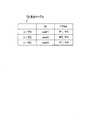
第1認証用DB15cは、図19に示す第1認証テーブルT4を保持している。この第1認証用DB15cには、認証データとして、例えば、ユーザ1の第1固有データであるID1=「user1」に、第1パスワードであるPW1=「aaa」が対応付けられている。更に、ユーザ1の第2固有データであるID2=「1」に、ID2の使用状況(使用中か否か)を表す「used」又は「unused」が対応付けられている。つまり、ユーザ1のID2と、使用状況と、ID1と、PW1とが相互に対応付けられている。 Thefirst authentication DB 15c holds a first authentication table T4 shown in FIG. As the authentication data, for example, ID1=“user1”, which is the first unique data of theuser 1, and PW1=“aaa”, which is the first password, are associated with thefirst authentication DB 15c. Furthermore, “used” or “unused” indicating the usage status (whether or not used) of ID2 is associated with ID2=“1” that is the second unique data of theuser 1. That is, the ID2 of theuser 1, the usage status, the ID1, and the PW1 are associated with each other.

同様に、ユーザ2のID1=「user2」に、PW1=「bbb」が対応付けられ、更に、ID2=「2」に「unused」が対応付けられている。ユーザ3のID1=「user3」に、PW1=「ccc」が対応付けられ、更に、ID2=「3」に「used」が対応付けられている。また、ユーザ2のID2には、第2パスワードであるPW2の「xxx」、「yyy」、「zzz」が対応付けられる。図19の第1認証テーブルT4の例では、ユーザ1が使用状況「used」のため、PW2の欄には何も対応付けられていない。ユーザ2は「unused」のため、PW2の欄には「yyy」が対応付けられ、ユーザ3は「used」のため、PW2の欄には何も対応付けられていない。何も対応付けられていないのは、後述のように、ユーザ追加時に、ユーザへのPW2の端末機11への通知後、削除する例示を行っているためである。 Similarly, PW1=“bbb” is associated with ID1=“user2” ofuser 2, and “unused” is associated with ID2=“2”.User 1's ID1=“user3” is associated with PW1=“ccc”, and further ID2=“3” is associated with “used”. Further, the ID2 of theuser 2 is associated with “xxx”, “yyy”, and “zzz” of the PW2 that is the second password. In the example of the first authentication table T4 in FIG. 19, since theuser 1 has the usage status “used”, nothing is associated with the column of PW2. Since theuser 2 is "unused", "yyy" is associated with the PW2 column, and theuser 3 is "used", so nothing is associated with the PW2 column. The reason why nothing is associated is that, as will be described later, when a user is added, the user is notified of the PW2 to the terminal device 11 and then deleted.

図20の右隅部分に破線枠で示すように、ID2は、第2パスワードであるPW2と対応付けられて、矢印Y30で示すようにFPGA装置16AのFPGA25(図21)に電子回路として書き込まれている。ID2及びPW2は、FPGA装置16Aに予めID2に対応付けられて固定的に記憶されており、システム管理者以外のユーザ等が変更不可能となっている。 As indicated by a broken line frame in the right corner portion of FIG. 20, ID2 is associated with the second password PW2 and written as an electronic circuit in the FPGA 25 (FIG. 21) of theFPGA device 16A as indicated by arrow Y30. ing. The ID2 and PW2 are fixedly stored in advance in theFPGA device 16A in association with the ID2, and cannot be changed by users other than the system administrator.

PW2は、ユーザがID1及びPW1を認証サーバ15Cに新規に登録してID2が使用中「used」となった際に、認証サーバ15Cからユーザの端末機11へ通知されるようになっている。FPGA装置16Aには、ID2=「1」にPW2=「xxx」が対応付けられ、ID2=「2」にPW2=「yyy」が、ID2=「3」にPW2=「zzz」が対応付けられて保持されている。 The PW2 is configured to notify the terminal 11 of the user from theauthentication server 15C when the user newly registers the ID1 and PW1 in theauthentication server 15C and the ID2 becomes “used” in use. In theFPGA device 16A, ID2=“1” is associated with PW2=“xxx”, ID2=“2” is associated with PW2=“yyy”, and ID2=“3” is associated with PW2=“zzz”. Is held.

次に、図20を参照して、第3実施形態の特徴について説明する。ユーザ(例えば、ユーザ1)が認証データの認証を行う際に、端末機11から矢印Y21で示すように、ID1=「user1」,PW1=「aaa」,PW2=「xxx」の認証データを認証サーバ15Cへ送信する。 Next, the features of the third embodiment will be described with reference to FIG. When the user (for example, the user 1) authenticates the authentication data, the terminal 11 authenticates the authentication data of ID1=“user1”, PW1=“aaa”, and PW2=“xxx” as shown by an arrow Y21. It is transmitted to theserver 15C.

認証サーバ15Cの第1認証用DB15cには、上述した認証データを保持する第1認証テーブルT4が保存されており、端末機11から送信されてきたユーザ1の認証データであるID1及びPW1と、第1認証テーブルT4のID1及びPW1とを比較して一致又は不一致の第1認証を行う。この認証結果が不一致の場合は、NGを矢印Y22で示すように、端末機11へ応答する。 Thefirst authentication DB 15c of theauthentication server 15C stores the first authentication table T4 holding the above-mentioned authentication data, and ID1 and PW1 which are the authentication data of theuser 1 transmitted from the terminal device 11, ID1 and PW1 of the first authentication table T4 are compared with each other to perform the matching or mismatching first authentication. If the authentication results do not match, the terminal 11 responds with NG, as indicated by the arrow Y22.

一方、第1認証がOKであれば、第2認証を行う。この第2認証は、第1認証用DB15cに保持されたユーザ1のID2=「1」をPW2=「aaa」と共に、矢印Y23で示すように、FPGA装置16Aへ送信する。FPGA装置16Aは、その送信されてきたユーザ1のID2=「1」及びPW2=「aaa」と、FPGA装置16Aに保持されたID2=「1」及びPW2=「aaa」を含む認証データとを比較し、一致又は不一致の第2認証を行う。この第2認証の結果は、矢印Y24,Y22で示すように認証サーバ15を介してユーザ1の端末機11へ応答される。 On the other hand, if the first authentication is OK, the second authentication is performed. In the second authentication, the ID2=“1” of theuser 1 held in thefirst authentication DB 15c is transmitted to theFPGA device 16A together with PW2=“aaa” as indicated by an arrow Y23. TheFPGA device 16A receives the ID2="1" and PW2="aaa" of theuser 1 and the authentication data including the ID2="1" and PW2="aaa" held in theFPGA device 16A. The second authentication is performed by comparing and matching or mismatching. The result of the second authentication is returned to the terminal 11 of theuser 1 via the authentication server 15 as indicated by arrows Y24 and Y22.

このように2段階で認証を行う構成は、ユーザが変更可能なPW1及びID1の追加、削除又は変更は認証サーバ15Cで行い、PW2はFPGA装置16Aに変更不可能に固定的に保存された構成となっている。このため、ユーザが変更可能なPW1の追加、削除又は変更は認証サーバ15Cのみで行うので、FPGA装置16Aでの認証データの書き換え処理が発生しないため、ユーザへの通信サービスの中断を抑制することが可能となっている。 In the configuration in which the authentication is performed in two steps as described above, the PW1 and the ID1 that can be changed by the user are added, deleted, or changed by theauthentication server 15C, and the PW2 is fixedly and permanently stored in theFPGA device 16A. Has become. Therefore, since the PW1 that can be changed by the user is added, deleted, or changed only by theauthentication server 15C, the rewriting process of the authentication data in theFPGA device 16A does not occur, so that the interruption of the communication service to the user is suppressed. Is possible.

<第3実施形態の認証構成>
図21に示す認証連携部21aは、端末機11からの認証リクエストを、ID1,PW1,PW2の認証データと共に受信する。ユーザ管理部21bは、その受信されたID1が、ユーザリスト用DB21cのユーザリストT1に登録されていなければ、端末機11への応答を行わない、又は、未登録案内をユーザ1の端末機11へ応答する。但し、ユーザリストT1は、図4に示したように「ID」を登録しているが、認証システム10Cの構成では、「ID」に代え、「ID1」を登録しているとする。
<Authentication configuration of the third embodiment>
Theauthentication cooperation unit 21a shown in FIG. 21 receives the authentication request from the terminal device 11 together with the authentication data of ID1, PW1, and PW2. If the received ID1 is not registered in the user list T1 of theuser list DB 21c, theuser management unit 21b does not respond to the terminal 11 or sends an unregistered guide to the terminal 11 of theuser 1. Respond to. However, although the user list T1 registers “ID” as shown in FIG. 4, it is assumed that “ID1” is registered instead of “ID” in the configuration of the authentication system 10C.

一方、ID1の登録が有れば、図21に示すユーザ管理部21bは、上記受信されたユーザ1のID1,PW1を、第1認証用DB15cに保持されたID1,PW1と比較して、一致又は不一致の第1認証を行う。この第1認証の結果がNGであれば、認証連携部21aは、NG結果を端末機11へ応答する。 On the other hand, if the ID1 is registered, theuser management unit 21b shown in FIG. 21 compares the received ID1 and PW1 of theuser 1 with the ID1 and PW1 held in thefirst authentication DB 15c, and matches them. Alternatively, the first authentication that does not match is performed. If the result of the first authentication is NG, theauthentication cooperation unit 21a returns the NG result to the terminal device 11.

第1認証の結果がOKであれば、認証連携部21aは、第1認証用DB15cに保持されたユーザ1のID2をPW2と共に、FPGA装置16Aへ送信する。FPGA装置16Aは、その送信されてきたユーザ1のID2,PW2と、FPGA25に回路として保持された認証データとを比較し、一致又は不一致の第2認証を行う。この第2認証の結果は、ユーザ1の端末機11へ応答される。 If the result of the first authentication is OK, theauthentication cooperation unit 21a transmits the ID2 of theuser 1 held in thefirst authentication DB 15c together with the PW2 to theFPGA device 16A. TheFPGA device 16A compares the transmitted ID2 and PW2 of theuser 1 with the authentication data held as a circuit in theFPGA 25, and performs the second authentication of matching or non-matching. The result of the second authentication is returned to the terminal 11 of theuser 1.

<第3実施形態のユーザ追加構成>
図21に示す認証連携部21aは、端末機11からのユーザ追加リクエストと共にID1,PW1の認証データを受信する。ユーザ管理部21bは、その受信された認証データのID1をユーザリストT1から検索する。この結果、例えば、追加対象ユーザ2のID1が登録済みであれば、認証連携部21aが、ユーザ2が登録済みであることを端末機11へ応答する。
<User Addition Configuration of Third Embodiment>
Theauthentication cooperation unit 21a illustrated in FIG. 21 receives the authentication data of ID1 and PW1 together with the user addition request from the terminal device 11. Theuser management unit 21b searches the user list T1 for ID1 of the received authentication data. As a result, for example, if ID1 of theaddition target user 2 is already registered, theauthentication cooperation unit 21a responds to the terminal device 11 that theuser 2 is already registered.

一方、ユーザリストT1にユーザ2のID1の登録が無ければ、ユーザ管理部21bは、第1認証用DB15cに、第1認証データとしてのユーザ2のID1,PW1を、ユーザが未使用(unused)のID2に対応付けて追加保持する。この追加により、ID2は使用中(used)となる。ユーザ管理部21bは、その使用中となったID2に対応付けられた第1認証テーブルT4(図19)のPW2を、追加ユーザの端末機11へ通知する。この通知後、PW2は第1認証テーブルT4から削除されるようになっている。また、ユーザ管理部21bは、ユーザリストT1にユーザ2のID1を追加する。 On the other hand, if there is no registration of the ID1 of theuser 2 in the user list T1, theuser management unit 21b uses the ID1 and PW1 of theuser 2 as the first authentication data in thefirst authentication DB 15c. It is additionally held in association with ID2. With this addition, ID2 becomes used. Theuser management unit 21b notifies the terminal 11 of the additional user of the PW2 of the first authentication table T4 (FIG. 19) associated with the ID2 that is in use. After this notification, PW2 is deleted from the first authentication table T4. Further, theuser management unit 21b adds the ID1 of theuser 2 to the user list T1.

<第3実施形態のユーザ削除構成>
図21に示す認証連携部21aは、端末機11からのユーザ削除リクエストと共にID1,PW1,PW2の認証データを受信する。ユーザ管理部21bは、その受信された認証データのID1をユーザリストT1から検索する。この結果、例えば、ユーザリストT1に、削除対象ユーザ1のID1の登録が無ければ削除の必要が無いので、認証連携部21aが、ユーザ1のID1が未登録ユーザであることを端末機11へ応答する。又は、端末機11への応答を行わない。
<User Deletion Configuration of Third Embodiment>
Theauthentication cooperation unit 21a illustrated in FIG. 21 receives the user deletion request from the terminal device 11 and the authentication data of ID1, PW1, and PW2. Theuser management unit 21b searches the user list T1 for ID1 of the received authentication data. As a result, for example, if there is no registration of the ID1 of theuser 1 to be deleted in the user list T1, there is no need to delete the ID. Therefore, theauthentication cooperation unit 21a notifies the terminal device 11 that the ID1 of theuser 1 is an unregistered user. respond. Alternatively, it does not respond to the terminal device 11.

一方、ユーザ1のID1の登録が有れば、ID1とPW1の組合せでPW認証を行う。この認証がOKであれば、ユーザ管理部21bは、DB21cのユーザリストT1に登録された削除対象のユーザ1のID1を削除し、この削除されたユーザ1のID1が存在しないユーザリストT1に更新する。更に、ユーザ管理部21bは、第1認証用DB15cから、削除対象ユーザ1の認証データを削除する。この削除結果は、認証連携部21aからユーザ1の端末機11へ応答される。 On the other hand, if the ID1 of theuser 1 is registered, PW authentication is performed using the combination of ID1 and PW1. If the authentication is OK, theuser management unit 21b deletes the ID1 of theuser 1 to be deleted registered in the user list T1 of theDB 21c, and updates the deleteduser 1 ID1 to the user list T1. To do. Furthermore, theuser management unit 21b deletes the authentication data of thedeletion target user 1 from thefirst authentication DB 15c. The deletion result is returned from theauthentication cooperation unit 21a to the terminal 11 of theuser 1.

<第3実施形態のユーザ認証データ変更構成>
図21に示す認証連携部21aは、端末機11からのユーザ認証データ変更リクエストと共にID1,PW1,PW2の認証データを受信する。ユーザ管理部21bは、その受信された認証データのID1をユーザリストT1から検索する。この結果、例えば、変更対象ユーザ1のID1の登録が無ければ、認証連携部21aが、ユーザ1が未登録ユーザであることを端末機11へ応答する。又は、端末機11への応答を行わない。
<User Authentication Data Change Configuration of Third Embodiment>
Theauthentication cooperation unit 21a shown in FIG. 21 receives the user authentication data change request from the terminal device 11 and the authentication data of ID1, PW1, and PW2. Theuser management unit 21b searches the user list T1 for ID1 of the received authentication data. As a result, for example, if the ID1 of thechange target user 1 is not registered, theauthentication cooperation part 21a responds to the terminal device 11 that theuser 1 is an unregistered user. Alternatively, it does not respond to the terminal device 11.

一方、変更対象ユーザ1のID1の登録が有れば、ID1とPW1の組合せでPW認証を行う。この認証がOKであれば、ユーザ管理部21bは、第1認証用DB15cに保存されたユーザ1のID1,PW1を変更して更新する。 On the other hand, if the ID1 of theuser 1 to be changed is registered, PW authentication is performed using the combination of ID1 and PW1. If the authentication is OK, theuser management unit 21b changes and updates the ID1 and PW1 of theuser 1 stored in thefirst authentication DB 15c.

<第3実施形態の認証動作>
次に、認証システム10Cによるユーザの認証データの認証動作を、図22に示すフローチャートを参照して説明する。但し、図22において、第1実施形態の図6と同一ステップには同一符号を付し、その説明を適宜省略する。
前提条件として、例えばユーザ1の端末機11から認証サーバ15Cへ、ユーザ1の認証リクエストが、認証データとしての図19に示すユーザ1のID1=「user1」,PW1=「aaa」と、PW2=「xxx」と共に送信されたとする。
<Authentication operation of the third embodiment>
Next, the authentication operation of the authentication data of the user by the authentication system 10C will be described with reference to the flowchart shown in FIG. However, in FIG. 22, the same steps as those in FIG. 6 of the first embodiment are denoted by the same reference numerals, and the description thereof will be appropriately omitted.
As a precondition, for example, the authentication request of theuser 1 from the terminal 11 of theuser 1 to theauthentication server 15C is the ID1 of theuser 1 shown in FIG. 19 as the authentication data=“user1”, PW1=“aaa”, and PW2= It is assumed that it is transmitted together with "xxx".

この際の図22に示すステップS1〜S4の処理は、第1実施形態の図6の説明と同様である。図22に示すステップS2の判定において、ユーザリストT1にユーザ1のID1が登録済み(Yes)であれば、ステップS90において、ユーザ管理部21bが、振分用DB15bから、上記受信されたユーザ1のID1,PW1を、第1認証用DB15cに保持されたID1,PW1と比較し、一致又は不一致の第1認証を行う。つまり、ステップS91において、第1認証がOKか否か(一致又は不一致か)を判定する。 The processing of steps S1 to S4 shown in FIG. 22 at this time is the same as the description of FIG. 6 of the first embodiment. If the ID1 of theuser 1 is already registered in the user list T1 in the determination in step S2 shown in FIG. 22 (Yes), theuser management unit 21b receives the receiveduser 1 from thedistribution DB 15b in step S90. ID1 and PW1 of No. 1 are compared with ID1 and PW1 held in thefirst authentication DB 15c, and the first authentication of matching or non-matching is performed. That is, in step S91, it is determined whether the first authentication is OK (match or mismatch).

第1認証の結果がOKでないNGであれば(No)、ステップS8において、NG結果が端末機11へ応答される。一方、第1認証の結果がOKであれば(Yes)、ステップS92において、第2認証が行われる。即ち、認証連携部21aが、第1認証用DB15cに保持されたユーザ1のID2をPW2と共に、FPGA装置16Aへ送信し、FPGA装置16Aが、その送信されてきたユーザ1のID2,PW2と、FPGA25に電子回路(認証回路)として保持された認証データとを比較し、一致又は不一致の第2認証を行う。この第2認証の結果は、ステップS8において、ユーザ1の端末機11へ応答される。 If the result of the first authentication is NG which is not OK (No), the NG result is returned to the terminal 11 in step S8. On the other hand, if the result of the first authentication is OK (Yes), the second authentication is performed in step S92. That is, theauthentication cooperation unit 21a transmits the ID2 of theuser 1 held in thefirst authentication DB 15c to theFPGA device 16A together with the PW2, and theFPGA device 16A transmits the ID2 and PW2 of theuser 1 transmitted. The authentication data held as an electronic circuit (authentication circuit) in theFPGA 25 is compared, and the second authentication of matching or non-matching is performed. The result of the second authentication is returned to the terminal 11 of theuser 1 in step S8.

<第3実施形態のユーザ追加動作>
次に、認証システム10Cによるユーザの認証データの追加動作を、図23に示すフローチャートを参照して説明する。但し、図23において、第1実施形態の図7と同一ステップには同一符号を付し、その説明を適宜省略する。
前提条件として、例えばユーザ2の端末機11から認証サーバ15へ、ユーザ2の追加リクエストが、認証データとしての図19に示すユーザ2のID1=「user2」,PW1=「bbb」と共に送信されたとする。
<User addition operation of the third embodiment>
Next, the operation of adding user authentication data by the authentication system 10C will be described with reference to the flowchart shown in FIG. However, in FIG. 23, the same steps as those of FIG. 7 of the first embodiment are denoted by the same reference numerals, and the description thereof will be appropriately omitted.
As a precondition, it is assumed that, for example, a request for adding theuser 2 is sent from the terminal 11 of theuser 2 to the authentication server 15 together with ID1=“user2” and PW1=“bbb” of theuser 2 shown in FIG. 19 as authentication data. To do.

図23に示すステップS11〜S14の処理は、第1実施形態の図7の説明と同様である。図23に示すステップS12の判定において、ユーザリストT1にユーザ2のID1の登録が無ければ(No)、ステップS94において、ユーザ管理部21bは、第1認証用DB15cに、第1認証データとしてのユーザ2のID1,PW1を、ユーザが未使用(unused)のID2に対応付けて追加保持する。この追加により、ID2は使用中(used)となる。 The processing of steps S11 to S14 shown in FIG. 23 is the same as the description of FIG. 7 of the first embodiment. In the determination of step S12 illustrated in FIG. 23, if the user list T1 does not have the ID1 of theuser 2 registered (No), theuser management unit 21b stores the first authentication data in thefirst authentication DB 15c in step S94. Theuser 1's ID1 and PW1 are additionally held in association with the user's unused ID2. With this addition, ID2 becomes used.

この際、ステップS94aにおいて、ユーザ管理部21bは、第1認証用DB15cにおいて、その使用中となったID2に対応付けられたPW2を、認証連携部21aから追加ユーザの端末機11へ通知する。この通知後にPW2を第1認証用DB15cから削除する。また、上記ステップS94の処理後、ステップS16において、ユーザ管理部21bは、ユーザリストT1にユーザ2のID1を追加する。この追加結果は、ステップS26において、ユーザ2の端末機11へ応答される。 At this time, in step S94a, theuser management unit 21b notifies the PW2 associated with the ID2 in use in thefirst authentication DB 15c from theauthentication cooperation unit 21a to the terminal 11 of the additional user. After this notification, PW2 is deleted from thefirst authentication DB 15c. After the process of step S94, theuser management unit 21b adds the ID1 of theuser 2 to the user list T1 in step S16. The addition result is returned to the terminal 11 of theuser 2 in step S26.

<第3実施形態のユーザ削除動作>
次に、認証システム10Cによるユーザの認証データの削除動作を、図24に示すフローチャートを参照して説明する。但し、図24において、図8と同一ステップには同一符号を付し、その説明を適宜省略する。
前提条件として、例えばユーザ1の端末機11から認証サーバ15へ、ユーザ1の削除リクエストが、認証データとしての図19に示すユーザ1のID1=「user1」,PW1=「aaa」と共に送信されたとする。
<User deletion operation of the third embodiment>
Next, the operation of deleting the user authentication data by the authentication system 10C will be described with reference to the flowchart shown in FIG. However, in FIG. 24, the same steps as those in FIG. 8 are designated by the same reference numerals, and the description thereof will be appropriately omitted.
As a precondition, for example, a request for deletinguser 1 is sent from the terminal 11 ofuser 1 to the authentication server 15 together with ID1=“user1” and PW1=“aaa” of theuser 1 shown in FIG. 19 as authentication data. To do.

図24に示すステップS31〜S35の処理は、第1実施形態の図8の説明と同様である。図24に示すステップS35のユーザリストT1に登録されたユーザ1のID1の削除による更新後、ステップS96において、ユーザ管理部21bは、第1認証用DB15cから、削除対象ユーザ1の状態フラグを「unused」に変更する。この削除結果は、ステップS46において、ユーザ1の端末機11へ応答される。 The processing of steps S31 to S35 shown in FIG. 24 is the same as the description of FIG. 8 of the first embodiment. After the update by deleting the ID1 of theuser 1 registered in the user list T1 in step S35 illustrated in FIG. 24, in step S96, theuser management unit 21b sets the status flag of thedeletion target user 1 to “1” in thefirst authentication DB 15c. changed to "unused". This deletion result is returned to the terminal 11 of theuser 1 in step S46.

<第3実施形態のユーザ認証データ変更動作>
次に、認証システム10Cによるユーザの認証データの変更動作を、図25に示すフローチャートを参照して説明する。但し、図25において、図9と同一ステップには同一符号を付し、その説明を適宜省略する。
前提条件として、例えばユーザ1の端末機11から認証サーバ15へ、ユーザ1のPWの変更リクエストが、認証データとしての図19に示すユーザ1のID1=「user1」,変更前のPW1(変更前PW)=「aaa」,変更後のPW1(変更PW1)=「aaa1」(図示せず)と共に送信されたとする。
<User authentication data changing operation of the third embodiment>
Next, the operation of changing the authentication data of the user by the authentication system 10C will be described with reference to the flowchart shown in FIG. However, in FIG. 25, the same steps as those in FIG. 9 are designated by the same reference numerals, and the description thereof will be appropriately omitted.
As a precondition, for example, a request to change the PW of theuser 1 from the terminal 11 of theuser 1 to the authentication server 15 is ID1 of theuser 1 shown in FIG. 19 as authentication data=“user1”, PW1 before the change (before the change). PW)=“aaa”, and PW1 after change (change PW1)=“aaa1” (not shown) is transmitted together.

図25に示すステップS51〜S54の処理は、第1実施形態の図9の説明と同様である。図25に示すステップS52の判定において、ユーザリストT1にユーザ1のID1の登録が有れば(Yes)、ステップS52aにおいて、図22の認証処理でPW認証を行う。この認証がOKであれば、ステップS98において、ユーザ管理部21bは、第1認証用DB15cに保存されたユーザ1のPW1を「aaa1」に変更して更新する。この後、ステップS67において、その変更結果がユーザ1の端末機11へ送信される。 The processing of steps S51 to S54 shown in FIG. 25 is the same as the description of FIG. 9 of the first embodiment. If it is determined in step S52 shown in FIG. 25 that the user list T1 has ID1 of the user 1 (Yes), PW authentication is performed in step S52a in the authentication process of FIG. If this authentication is OK, in step S98, theuser management unit 21b changes the PW1 of theuser 1 stored in thefirst authentication DB 15c to “aaa1” and updates it. Then, in step S67, the change result is transmitted to the terminal device 11 of theuser 1.

上記はユーザ1のPW1の変更の処理であるが、ID1も変更、例えば、ID1=「user11」(図示せず)に変更する場合は、上記ステップS51〜54,S98において、ID1についてPW1と同様の処理を行う。この後、ステップS98aにおいて、ユーザ管理部21bが、ユーザリストT1において、未だ変更されていない変更対象ユーザ1のID1を、ID1=「user11」に変更する。このID1の変更結果も、ステップS67において、ユーザ1の端末機11へ応答される。 The above is the process of changing the PW1 of theuser 1. However, when changing the ID1 as well, for example, changing to ID1=“user11” (not shown), in steps S51 to S54 and S98, the ID1 is the same as the PW1. Process. After that, in step S98a, theuser management unit 21b changes the ID1 of thechange target user 1 that has not been changed in the user list T1 to ID1=“user11”. The change result of ID1 is also returned to the terminal device 11 of theuser 1 in step S67.

<第3実施形態の効果>
以上説明したように、第3実施形態の認証システム10Cは、次のような特徴構成とした。
<Effects of Third Embodiment>
As described above, the authentication system 10C of the third embodiment has the following characteristic configuration.

(1)認証データとして、ユーザが変更可能なID1及びPW1と、変更不可能なPW2に対応付けられるID2と、を保持する第1認証用DB15cを有する認証サーバ15Cを備える。FPGA装置16Aは、ID2及びPW2の対を複数、電子回路で置換して保持している。認証サーバ15Cは、端末機11から受信したID1及びPW1を、第1認証用DB15cに保持されたID1及びPW1と比較して一致又は不一致で認証する第1認証を行う。認証サーバ15Cは、その第1認証が一致の場合に、この一致したPW1に第1認証用DB15cに対応付けられたID2と、端末機11からID1と共に受信したPW2とを対にしてFPGA装置16Aへ送信する。FPGA装置16Aは、送信されてきた対のID2及びPW2を、FPGA装置16Aに保持されたID2及びPW2と比較して認証する第2認証を行う構成とした。 (1) Theauthentication server 15C includes afirst authentication DB 15c that holds ID1 and PW1 that can be changed by a user and ID2 that is associated with an unchangeable PW2 as authentication data. TheFPGA device 16A replaces and holds a plurality of pairs of ID2 and PW2 with electronic circuits. Theauthentication server 15C compares the ID1 and PW1 received from the terminal 11 with the ID1 and PW1 held in thefirst authentication DB 15c, and performs the first authentication to authenticate with a match or a mismatch. If the first authentication matches, theauthentication server 15C pairs the matched PW1 with the ID2 associated with thefirst authentication DB 15c and the PW2 received from the terminal 11 together with the ID1 and theFPGA device 16A. Send to. TheFPGA device 16A is configured to perform the second authentication in which the transmitted ID2 and PW2 of the pair are compared with the ID2 and PW2 held in theFPGA device 16A for authentication.

この構成によれば、ユーザが変更可能なID1及びPW1の認証データは認証サーバ15Cの第1認証用DB15cに保持され、変更不可能なID2及びPW2の認証データはFPGA装置16Aに電子回路で置換されて保持されている。このため、ユーザが変更可能な認証データの追加、削除又は変更等は、認証サーバ15Cのみで行うことができるので、FPGA装置16Aでは認証データの書き換え処理が発生しない。これにより、ユーザへの通信サービスの中断を抑制することができる。 According to this configuration, the user-changeable authentication data of ID1 and PW1 is held in thefirst authentication DB 15c of theauthentication server 15C, and the unchangeable authentication data of ID2 and PW2 is replaced by theFPGA device 16A by an electronic circuit. Has been held. For this reason, the addition, deletion, or change of the authentication data that can be changed by the user can be performed only by theauthentication server 15C, so that theFPGA device 16A does not rewrite the authentication data. As a result, the interruption of the communication service to the user can be suppressed.

(2)認証サーバ15Cは、端末機11からのユーザ追加のリクエスト時に、当該追加対象である追加ユーザのID1及びPW1が未登録の場合に、当該追加ユーザのID1及びPW1を第1認証用DB15cに、未使用中のID2に対応付けて保存し、この保持により使用中となったID2に対応付けられたPW2を、追加ユーザの端末機11へ通知する構成とした。 (2) Theauthentication server 15C, when requesting the user addition from the terminal device 11, if the ID1 and PW1 of the additional user who is the addition target is not registered, sets the ID1 and PW1 of the additional user to thefirst authentication DB 15c. In addition, the PW2 associated with the unused ID2 is stored, and the PW2 associated with the ID2 that is in use due to this retention is notified to the terminal 11 of the additional user.

この構成によれば、認証サーバ15Cにユーザの認証データの追加を行った際に、その後、ユーザが認証データの認証等を行う際に必要なPW2を安全に得ることができる。 According to this configuration, when the user authentication data is added to theauthentication server 15C, the PW2 required when the user subsequently authenticates the authentication data can be obtained safely.

その他、具体的な構成について、本発明の主旨を逸脱しない範囲で適宜変更が可能である。 In addition, the specific configuration can be appropriately changed without departing from the gist of the present invention.

10A,10B,10C プログラマブルデバイス適用認証システム
11 クライアント端末機(端末機)
12 インターネット
13 社内NW
14 APサーバ
15A,15B,15C 認証サーバ
15a キャッシュ用DB(データベース)
15b 振分用DB(データベース)
15c 第1認証用DB(データベース)
16A,16B FPGA装置(プログラマブルデバイス装置)
17 プライベートNW
21 AP認証部
21a 認証連携部
21b ユーザ管理部
21c ユーザリスト用DB
22 認証制御部
22a HDL生成部
22b HDL用DB
22c コンフィグデータ生成部
22d FPGA再起動部
25,25a,25b,25c FPGA
26 ハード制御部
26a FPGA書換部
26b コンフィグデータ用DB
26c FPGA電源部
27 認証部
27a 受付回路
27b 認証回路
10A, 10B, 10C Programmable device application authentication system 11 Client terminal (terminal)
12 Internet 13 In-house NW
14AP server 15A, 15B,15C Authentication server 15a Cache DB (database)
15b Sorting DB (database)
15c First authentication DB (database)
16A, 16B FPGA device (programmable device device)
17 Private NW
21AP authentication unit 21aAuthentication cooperation unit 21bUser management unit 21c User list DB
22Authentication control unit 22aHDL generation unit 22b HDL DB
22c configdata generation unit 22dFPGA restart unit 25, 25a, 25b, 25c FPGA
26hardware control unit 26aFPGA rewriting unit 26b configuration data DB
26c FPGApower supply unit 27authentication unit27a reception circuit 27b authentication circuit

Claims (5)

Translated fromJapanese
固有の認証データを電子回路に置換して保持するプログラマブルデバイス装置によって、端末機から送信されてきたユーザ固有の認証データを、前記電子回路として保持された認証データと比較して認証を行うプログラマブルデバイス適用認証システムであって、
前記ユーザ固有の認証データをキャッシュするデータベースを有し、当該データベースにキャッシュされた認証データを、バッチ処理で前記プログラマブルデバイス装置に電子回路への置換を行わせるための転送を行い、この転送後に前記キャッシュされた認証データを削除する認証サーバ
を備え、
前記認証サーバは、前記端末機からのユーザの認証データを受信した際に、前記データベースに同ユーザの認証データがキャッシュされていれば、当該受信した認証データを、当該キャッシュされた認証データと比較して認証を行い、キャッシュされていなければ前記プログラマブルデバイス装置に電子回路として保持された認証データと比較して認証を行わせる
ことを特徴とするプログラマブルデバイス適用認証システム。
A programmable device that performs authentication by comparing the user-specific authentication data transmitted from the terminal with the authentication data held as the electronic circuit by a programmable device device that replaces and holds the unique authentication data with an electronic circuit. An applied authentication system,
Having a database that caches the authentication data unique to the user, the authentication data cached in the database is transferred in batch processing to cause the programmable device device to replace it with an electronic circuit, and after this transfer, Equipped with an authentication server that deletes cached authentication data,
When the authentication server receives the authentication data of the user from the terminal, if the authentication data of the user is cached in the database, the authentication server compares the received authentication data with the cached authentication data. A programmable device-applied authentication system, characterized in that the programmable device is authenticated by comparing it with the authentication data held as an electronic circuit if it is not cached.
前記認証サーバは、
前記端末機からのユーザ追加のリクエスト時に、その追加対象である追加ユーザの認証データが未登録の場合に、前記データベースに当該追加ユーザの認証データを追加してキャッシュし、このキャッシュされた認証データを含む全ユーザの認証データを、前記バッチ処理で前記プログラマブルデバイス装置に転送し、
前記プログラマブルデバイス装置は、
前記転送されてきた前記追加ユーザの認証データを含む全ユーザの認証データを、前記電子回路に置換して保持する
ことを特徴とする請求項1に記載のプログラマブルデバイス適用認証システム。
The authentication server is
At the time of requesting a user addition from the terminal, if the authentication data of the additional user to be added is not registered, the authentication data of the additional user is added to the database and cached, and the cached authentication data is added. Transfer authentication data of all users including, to the programmable device device in the batch process,
The programmable device device,
The programmable device application authentication system according to claim 1, wherein all the user authentication data including the transferred authentication data of the additional user is replaced with the electronic circuit and held.
前記認証サーバは、
前記端末機からのユーザ削除のリクエスト時に、その削除対象である削除ユーザの認証データが登録有りの場合に、前記データベースに当該削除ユーザの認証データがキャッシュされていれば、当該キャッシュされた認証データを削除し、この削除が反映された全ユーザの認証データを、前記バッチ処理で前記プログラマブルデバイス装置に転送し、
前記プログラマブルデバイス装置は、
前記転送されてきた前記削除が反映された全ユーザの認証データを、前記電子回路に置換して保持する
ことを特徴とする請求項1に記載のプログラマブルデバイス適用認証システム。
The authentication server is
If the deletion user authentication data to be deleted is registered when the user deletion request is made from the terminal, and if the deletion user authentication data is cached in the database, the cached authentication data is deleted. Is deleted, and the authentication data of all users in which this deletion is reflected is transferred to the programmable device device by the batch processing,
The programmable device device,
The programmable device application authentication system according to claim 1, wherein the transferred authentication data of all the users, in which the deletion is reflected, is replaced with the electronic circuit and held.
前記認証サーバは、
前記端末機からのユーザ認証データ変更のリクエスト時に、その変更対象の変更ユーザの認証データが登録有りの場合に、前記データベースに当該変更ユーザの認証データがキャッシュされていれば、当該キャッシュされた認証データを変更し、この変更が反映された全ユーザの認証データを、前記バッチ処理で前記プログラマブルデバイス装置に転送し、
前記プログラマブルデバイス装置は、
前記転送されてきた前記変更が反映された全ユーザの認証データを、前記電子回路に置換して保持する
ことを特徴とする請求項1に記載のプログラマブルデバイス適用認証システム。
The authentication server is
When the user authentication data change request from the terminal is registered and the changed user authentication data is registered, if the changed user authentication data is cached in the database, the cached authentication is performed. Change the data, transfer the authentication data of all users reflected this change to the programmable device device in the batch processing,
The programmable device device,
The programmable device application authentication system according to claim 1, wherein the transferred authentication data of all users in which the change is reflected is stored in the electronic circuit by being replaced.
固有の認証データを電子回路に置換して保持するプログラマブルデバイス装置によって、端末機から送信されてきたユーザ固有の認証データを、前記電子回路として保持された認証データと比較して認証を行うプログラマブルデバイス適用認証システムの認証方法であって、
前記プログラマブルデバイス適用認証システムは、
ユーザ固有の認証データをキャッシュするデータベースを有し、当該データベースにキャッシュされた認証データを、バッチ処理で前記プログラマブルデバイス装置に電子回路への置換を行わせるための転送を行い、この転送後に前記キャッシュされた認証データを削除する認証サーバを備え、
前記認証サーバは、
前記端末機からのユーザの認証データを受信した際に、前記データベースに同ユーザの認証データがキャッシュされていれば、当該受信した認証データを、当該キャッシュされた認証データと比較して認証を行い、キャッシュされていなければ前記プログラマブルデバイス装置に電子回路として保持された認証データと比較して認証を行わせるステップ
を実行することを特徴とする認証方法。
A programmable device that performs authentication by comparing the user-specific authentication data transmitted from the terminal with the authentication data held as the electronic circuit by a programmable device device that replaces and holds the unique authentication data with an electronic circuit. An authentication method of an applied authentication system,
The programmable device application authentication system,
Having a database that caches user-specific authentication data, the authentication data cached in the database is transferred in batch processing to cause the programmable device device to replace it with an electronic circuit, and after this transfer, the cache Equipped with an authentication server that deletes the registered authentication data,
The authentication server is
When the authentication data of the user is received from the terminal, if the authentication data of the user is cached in the database, the received authentication data is compared with the cached authentication data to perform authentication. An authentication method, characterized in that, if not cached, a step of causing the programmable device device to perform authentication by comparing with authentication data held as an electronic circuit is performed.
JP2017037098A2017-02-282017-02-28 Programmable device application authentication system and authentication methodActiveJP6712112B2 (en)

Priority Applications (3)

Application NumberPriority DateFiling DateTitle
JP2017037098AJP6712112B2 (en)2017-02-282017-02-28 Programmable device application authentication system and authentication method
JP2020057138AJP6904453B2 (en)2017-02-282020-03-27 Programmable device application authentication system and authentication method
JP2020057137AJP6904452B2 (en)2017-02-282020-03-27 Programmable device application authentication system and authentication method

Applications Claiming Priority (1)

Application NumberPriority DateFiling DateTitle
JP2017037098AJP6712112B2 (en)2017-02-282017-02-28 Programmable device application authentication system and authentication method

Related Child Applications (2)

Application NumberTitlePriority DateFiling Date
JP2020057137ADivisionJP6904452B2 (en)2017-02-282020-03-27 Programmable device application authentication system and authentication method
JP2020057138ADivisionJP6904453B2 (en)2017-02-282020-03-27 Programmable device application authentication system and authentication method

Publications (2)

Publication NumberPublication Date
JP2018142253A JP2018142253A (en)2018-09-13
JP6712112B2true JP6712112B2 (en)2020-06-17

Family

ID=63528187

Family Applications (1)

Application NumberTitlePriority DateFiling Date
JP2017037098AActiveJP6712112B2 (en)2017-02-282017-02-28 Programmable device application authentication system and authentication method

Country Status (1)

CountryLink
JP (1)JP6712112B2 (en)

Families Citing this family (2)

* Cited by examiner, † Cited by third party
Publication numberPriority datePublication dateAssigneeTitle
CN110879811B (en)*2019-11-182023-05-23浪潮通用软件有限公司Implementation method for carrying out data and program consistency self-check during running
JP2023000645A (en)*2021-06-182023-01-04キヤノン株式会社 Power Receiving Device, Power Transmitting Device, Control Method, and Program

Also Published As

Publication numberPublication date
JP2018142253A (en)2018-09-13

Similar Documents

PublicationPublication DateTitle
CN1332301C (en) Delivery method, delivery system and terminal equipment
EP3510743B1 (en)Interchangeable retrieval of sensitive content via private content distribution networks
JP6376869B2 (en) Data synchronization system, control method thereof, authorization server, and program thereof
US10555147B2 (en)Systems and methods for facilitating service provision between applications
JP2009087035A (en) Cryptographic client device, cryptographic package distribution system, cryptographic container distribution system, cryptographic management server device, software module management device, software module management program
US11665532B2 (en)Securing private wireless gateways
WO2019201040A1 (en)File update management method and system and terminal apparatus
CN107920081A (en)Login authentication method and device
US11063922B2 (en)Virtual content repository
CN110163003B (en)Password management method and device
JP2011215753A (en)Authentication system and authentication method
US11184431B2 (en)System and control method
JP6712112B2 (en) Programmable device application authentication system and authentication method
JP6904453B2 (en) Programmable device application authentication system and authentication method
WO2025035982A1 (en)Cloud container multi-level access method, apparatus, storage medium, and chip
JP2008027202A (en)Session management method, server used for the same, session management program, and recording medium with recorded program
JP6904452B2 (en) Programmable device application authentication system and authentication method
JP4887129B2 (en) Update information generation apparatus, identification information update system, identification information update method and program
JP2008187479A (en)Data management server, data management method, and program
CN103701844A (en)User information management method and system
JP2006229735A (en)Information processing apparatus and system
CN111756675B (en)Data processing method, device, equipment and system
JP7640232B2 (en) COMMUNICATION SYSTEM, RELAY PROCESSING DEVICE, INFORMATION PROCESSING METHOD, AND PROGRAM
JP2008269220A (en)Authentication transfer system, authentication transfer method, terminal device and authentication server
JP6083210B2 (en) Authentication information management system, authentication information management method, authentication information management program, and search system

Legal Events

DateCodeTitleDescription
A621Written request for application examination

Free format text:JAPANESE INTERMEDIATE CODE: A621

Effective date:20190308

A977Report on retrieval

Free format text:JAPANESE INTERMEDIATE CODE: A971007

Effective date:20200122

A131Notification of reasons for refusal

Free format text:JAPANESE INTERMEDIATE CODE: A131

Effective date:20200128

A521Request for written amendment filed

Free format text:JAPANESE INTERMEDIATE CODE: A523

Effective date:20200327

TRDDDecision of grant or rejection written
A01Written decision to grant a patent or to grant a registration (utility model)

Free format text:JAPANESE INTERMEDIATE CODE: A01

Effective date:20200526

A61First payment of annual fees (during grant procedure)

Free format text:JAPANESE INTERMEDIATE CODE: A61

Effective date:20200528

R150Certificate of patent or registration of utility model

Ref document number:6712112

Country of ref document:JP

Free format text:JAPANESE INTERMEDIATE CODE: R150

S533Written request for registration of change of name

Free format text:JAPANESE INTERMEDIATE CODE: R313533

R350Written notification of registration of transfer

Free format text:JAPANESE INTERMEDIATE CODE: R350


[8]ページ先頭

©2009-2025 Movatter.jp