JP6710066B2 - Catheter handle and catheter having the same - Google Patents
Catheter handle and catheter having the sameDownload PDFInfo
- Publication number
- JP6710066B2 JP6710066B2JP2016043925AJP2016043925AJP6710066B2JP 6710066 B2JP6710066 B2JP 6710066B2JP 2016043925 AJP2016043925 AJP 2016043925AJP 2016043925 AJP2016043925 AJP 2016043925AJP 6710066 B2JP6710066 B2JP 6710066B2
- Authority
- JP
- Japan
- Prior art keywords
- handle
- guide member
- wire guide
- turntable
- catheter
- Prior art date
- Legal status (The legal status is an assumption and is not a legal conclusion. Google has not performed a legal analysis and makes no representation as to the accuracy of the status listed.)
- Active
Links
- 230000002093peripheral effectEffects0.000claimsdescription4
- 238000005452bendingMethods0.000description10
- 230000000149penetrating effectEffects0.000description9
- 229920003002synthetic resinPolymers0.000description5
- 239000000057synthetic resinSubstances0.000description5
- BASFCYQUMIYNBI-UHFFFAOYSA-NplatinumChemical compound[Pt]BASFCYQUMIYNBI-UHFFFAOYSA-N0.000description4
- -1polyethylenePolymers0.000description4
- 210000004204blood vesselAnatomy0.000description3
- 230000006835compressionEffects0.000description3
- 238000007906compressionMethods0.000description3
- 238000006073displacement reactionMethods0.000description3
- 238000003780insertionMethods0.000description3
- 230000037431insertionEffects0.000description3
- 229920006122polyamide resinPolymers0.000description3
- XEEYBQQBJWHFJM-UHFFFAOYSA-NIronChemical compound[Fe]XEEYBQQBJWHFJM-UHFFFAOYSA-N0.000description2
- 239000004677NylonSubstances0.000description2
- 239000004696Poly ether ether ketoneSubstances0.000description2
- 239000004698PolyethyleneSubstances0.000description2
- 239000004721Polyphenylene oxideSubstances0.000description2
- 239000004743PolypropyleneSubstances0.000description2
- 229910045601alloyInorganic materials0.000description2
- 239000000956alloySubstances0.000description2
- 206010003119arrhythmiaDiseases0.000description2
- 230000006793arrhythmiaEffects0.000description2
- 125000003118aryl groupChemical group0.000description2
- JUPQTSLXMOCDHR-UHFFFAOYSA-Nbenzene-1,4-diol;bis(4-fluorophenyl)methanoneChemical compoundOC1=CC=C(O)C=C1.C1=CC(F)=CC=C1C(=O)C1=CC=C(F)C=C1JUPQTSLXMOCDHR-UHFFFAOYSA-N0.000description2
- 229920000840ethylene tetrafluoroethylene copolymerPolymers0.000description2
- 210000001035gastrointestinal tractAnatomy0.000description2
- 239000000463materialSubstances0.000description2
- 229920001778nylonPolymers0.000description2
- 229920011301perfluoro alkoxyl alkanePolymers0.000description2
- 229910052697platinumInorganic materials0.000description2
- 229920001225polyester resinPolymers0.000description2
- 239000004645polyester resinSubstances0.000description2
- 229920000570polyetherPolymers0.000description2
- 229920002530polyetherether ketonePolymers0.000description2
- 229920000573polyethylenePolymers0.000description2
- 229920001721polyimidePolymers0.000description2
- 239000009719polyimide resinSubstances0.000description2
- 229920005672polyolefin resinPolymers0.000description2
- 229920001155polypropylenePolymers0.000description2
- 239000004810polytetrafluoroethyleneSubstances0.000description2
- 229920001343polytetrafluoroethylenePolymers0.000description2
- 229920005989resinPolymers0.000description2
- 239000011347resinSubstances0.000description2
- 210000000626ureterAnatomy0.000description2
- 229910000975Carbon steelInorganic materials0.000description1
- RYGMFSIKBFXOCR-UHFFFAOYSA-NCopperChemical compound[Cu]RYGMFSIKBFXOCR-UHFFFAOYSA-N0.000description1
- 229910052782aluminiumInorganic materials0.000description1
- XAGFODPZIPBFFR-UHFFFAOYSA-NaluminiumChemical compound[Al]XAGFODPZIPBFFR-UHFFFAOYSA-N0.000description1
- 230000004323axial lengthEffects0.000description1
- 239000010962carbon steelSubstances0.000description1
- 229910052802copperInorganic materials0.000description1
- 239000010949copperSubstances0.000description1
- PCHJSUWPFVWCPO-UHFFFAOYSA-NgoldChemical compound[Au]PCHJSUWPFVWCPO-UHFFFAOYSA-N0.000description1
- 229910052737goldInorganic materials0.000description1
- 239000010931goldSubstances0.000description1
- 230000012447hatchingEffects0.000description1
- 229910052742ironInorganic materials0.000description1
- 150000002576ketonesChemical class0.000description1
- WABPQHHGFIMREM-UHFFFAOYSA-Nlead(0)Chemical group[Pb]WABPQHHGFIMREM-UHFFFAOYSA-N0.000description1
- 229910052751metalInorganic materials0.000description1
- 239000002184metalSubstances0.000description1
- 239000007769metal materialSubstances0.000description1
- 238000012986modificationMethods0.000description1
- 230000004048modificationEffects0.000description1
- 229910001000nickel titaniumInorganic materials0.000description1
- 229920001643poly(ether ketone)Polymers0.000description1
- 229920005749polyurethane resinPolymers0.000description1
- 238000011084recoveryMethods0.000description1
- 239000010935stainless steelSubstances0.000description1
- 229910001220stainless steelInorganic materials0.000description1
Images


Landscapes
- Media Introduction/Drainage Providing Device (AREA)
Description
Translated fromJapanese本発明は、医療用カテーテルに用いられるカテーテル用ハンドルと、それを備えたカテーテルに関するものである。 The present invention relates to a catheter handle used for a medical catheter and a catheter provided with the same.
医療用カテーテルは、通常、血管や消化管や尿管などの体内の管腔部に挿入するためのチューブ体と、チューブ体の近位側に設けられたハンドルとから構成されている。カテーテルには、手元のハンドルを操作してチューブ体の遠位側を屈曲できるように構成されたものが知られており、このようなカテーテルは、チューブ体の内腔に、チューブ体の遠位側に固定された1本または2本のワイヤが配され、ワイヤの近位側がハンドルに接続され、ハンドルを操作してワイヤをハンドル側に引っ張ることにより、チューブ体の遠位側を屈曲できるようになっている。ワイヤが2本配されたカテーテルでは、2本のワイヤの一方を引っ張ることでチューブ体の遠位側を第1方向に屈曲させ、他方を引っ張ることでチューブ体の遠位側を第1方向とは反対側の第2方向に屈曲させることができる。 A medical catheter is usually composed of a tube body for insertion into a lumen of a body such as a blood vessel, a digestive tract, or a ureter, and a handle provided on the proximal side of the tube body. It is known that a catheter is configured so that the distal side of the tube body can be bent by operating a handle at the hand, and such a catheter is disposed in the lumen of the tube body at the distal end of the tube body. One or two wires fixed to the side are arranged, the proximal side of the wire is connected to the handle, and the distal side of the tube body can be bent by operating the handle and pulling the wire toward the handle side. It has become. In a catheter having two wires, by pulling one of the two wires, the distal side of the tube is bent in the first direction, and by pulling the other, the distal side of the tube is set as the first direction. Can be bent in the opposite second direction.
例えば特許文献1には、チューブ部材の近位端側に装着された操作用ハブと、操作用ハブに回動自在に装着され、ワイヤの近位端が接続された回動摘みとを有するカテーテルが開示されており、このカテーテルは、回動摘みを第1方向または第2方向に回動することによりチューブ部材の遠位端の向きを変化できるようになっている。特許文献2には、カテーテルチューブの基端側に装着されるハンドル本体と、ハンドル本体に対して回転自在に装着され、ワイヤの基端が固定される回転板を備えたカテーテル用ハンドルが開示され、この回転板には、回転板内におけるワイヤの経路を規定するための円弧状または円環上の複数のガイドレールが、回転軸を中心とする同心円の円周上に形成されている。特許文献2のカテーテル用ハンドルでは、ワイヤを配するガイドレールを適宜選択することで、回転板を回転させたときのワイヤの牽引長を変えることができ、それに応じてカテーテルチューブの先端部分の曲がりの大きさを変えることができる。 For example, in
特許文献1,2に開示されたカテーテルやカテーテル用ハンドルによれば、回動摘みや回転板の回転角度を調整したり、ワイヤを配するガイドレールを適宜選択することで、チューブ体の遠位側の屈曲の程度を変えることができるが、さらに使い勝手の良いカテーテルが求められている。本発明は前記事情に鑑みてなされたものであり、その目的は、カテーテルに装着して用いられるハンドルであって、ハンドル操作によってカテーテルのチューブ体の遠位側の屈曲の程度を自在に調整することができるカテーテル用ハンドルを提供することにある。 According to the catheter and the catheter handle disclosed in
前記課題を解決することができた本発明のカテーテル用ハンドルとは、ハンドル本体と、ハンドル本体に対して回転自在に設けられた回転盤と、回転盤の平面方向に変位可能に形成されたワイヤガイド部材とを有するところに特徴を有する。本発明のカテーテル用ハンドルを用いれば、ワイヤガイド部材を回転盤の平面方向に変位させることにより、回転盤を回転させた際に、ワイヤガイド部材に沿って配されたワイヤの牽引長を自在に調整することができる。そのため、回転盤を回転させた際のチューブ体の遠位側の屈曲の程度を使用者の好みやニーズに応じて調整でき、使い勝手の良いカテーテルとすることができる。 The catheter handle of the present invention that has been able to solve the above-mentioned problems includes a handle main body, a rotary disc rotatably provided with respect to the handle main body, and a wire formed so as to be displaceable in the plane direction of the rotary disc. It is characterized by having a guide member. By using the handle for a catheter of the present invention, by displacing the wire guide member in the plane direction of the turntable, the pulling length of the wire arranged along the wire guide member can be freely set when the turntable is rotated. Can be adjusted. Therefore, the degree of bending on the distal side of the tube body when the turntable is rotated can be adjusted according to the preference and needs of the user, and the catheter can be easily used.
ワイヤガイド部材は、ハンドル本体に対して回転自在に設けられていてもよく、ハンドル本体に対して回転不能に設けられていてもよい。いずれの場合もワイヤガイド部材を回転盤の平面方向に変位させることで、回転盤を回転させたときのワイヤの牽引長を調整することができる。 The wire guide member may be rotatably provided with respect to the handle body, or may be non-rotatably provided with respect to the handle body. In either case, by displacing the wire guide member in the plane direction of the turntable, the pulling length of the wire when the turntable is rotated can be adjusted.
ワイヤガイド部材が回転盤とともにハンドル本体に対して回転自在に設けられる場合、カテーテル用ハンドルは、回転盤に溝が形成され、ワイヤガイド部材に凸部が設けられ、凸部が溝を貫通していることが好ましい。ワイヤガイド部材がハンドル本体に対して回転不能に設けられる場合は、カテーテル用ハンドルは、ハンドル本体に溝が形成され、ワイヤガイド部材に凸部が設けられ、凸部が溝を貫通していることが好ましい。このようにハンドルが構成されていれば、ワイヤガイド部材の凸部をハンドルの外側から操作して、簡単にワイヤガイド部材を回転盤の平面方向に変位させることができる。さらにこの場合、ワイヤガイド部材は、ハンドルの外側から操作して、回転盤の回転軸方向に移動可能に形成されていることが好ましい。これにより、ハンドルの外側から操作して、ワイヤガイド部材を回転盤またはハンドル本体に固定させたり、回転盤またはハンドル本体から離して平面方向に変位させやすくすることができ、ハンドルの取り扱い性を向上させることができる。 When the wire guide member is rotatably provided together with the turntable with respect to the handle body, the catheter handle has a groove formed on the turntable, the wire guide member is provided with a protrusion, and the protrusion penetrates the groove. Is preferred. When the wire guide member is non-rotatably provided with respect to the handle body, the catheter handle has a groove formed in the handle body, the wire guide member is provided with a convex portion, and the convex portion penetrates the groove. Is preferred. If the handle is configured as described above, the wire guide member can be easily displaced in the plane direction of the turntable by operating the convex portion of the wire guide member from the outside of the handle. Furthermore, in this case, it is preferable that the wire guide member is formed so as to be movable from the outside of the handle in the direction of the rotation axis of the turntable. This allows the wire guide member to be fixed to the turntable or handle body by operating it from the outside of the handle, or it can be easily displaced in the plane direction away from the turntable or handle body, improving handleability. Can be made
ワイヤガイド部材は複数設けられていてもよい。ワイヤガイド部材が複数設けられていれば、それぞれのワイヤガイド部材を回転盤の平面方向に変位させることにより、回転盤の回転軸を挟んで一方側に配置したワイヤと他方側に配置したワイヤのそれぞれの牽引長を自在に調整することができる。 A plurality of wire guide members may be provided. If a plurality of wire guide members are provided, by displacing each wire guide member in the plane direction of the turntable, the wire placed on one side and the wire placed on the other side with the rotary shaft of the turntable sandwiched therebetween are sandwiched. Each tow length can be adjusted freely.
本発明はまた、本発明のカテーテル用ハンドルと、カテーテル用ハンドルの遠位側に設けられたチューブ体と、遠位側がチューブ体に固定され、近位側がハンドルに固定されたワイヤを有し、ワイヤが、ワイヤガイド部材の外周側に接するように回転盤に配されているカテーテルも提供する。本発明のカテーテルによれば、ハンドルに設けられたワイヤガイド部材を回転盤の平面方向に変位させることにより、回転盤を回転させた際のチューブ体の遠位側の屈曲の程度を自在に調整でき、使い勝手の良いものとすることができる。 The present invention also has a catheter handle of the present invention, a tube body provided on the distal side of the catheter handle, and a wire fixed to the tube body on the distal side and fixed on the handle on the proximal side, There is also provided a catheter in which the wire is arranged on the turntable so as to contact the outer peripheral side of the wire guide member. According to the catheter of the present invention, by displacing the wire guide member provided on the handle in the plane direction of the turntable, the degree of bending of the tube body on the distal side when the turntable is rotated can be freely adjusted. It can be done and is easy to use.
本発明のカテーテル用ハンドルを用いれば、ワイヤガイド部材を回転盤の平面方向に変位させることにより、回転盤を回転させた際に、ワイヤガイド部材に沿って配されたワイヤの牽引長を自在に調整することができる。そのため、回転盤を回転させた際のチューブ体の遠位側の屈曲の程度を使用者の好みやニーズに応じて調整でき、使い勝手の良いカテーテルとすることができる。 By using the handle for a catheter of the present invention, by displacing the wire guide member in the plane direction of the turntable, the pulling length of the wire arranged along the wire guide member can be freely set when the turntable is rotated. Can be adjusted. Therefore, the degree of bending on the distal side of the tube body when the turntable is rotated can be adjusted according to the preference and needs of the user, and the catheter can be easily used.
本発明は、医療用カテーテルに用いられるカテーテル用ハンドルに関するものであり、カテーテルに設けられるチューブ体の遠位側を屈曲させる操作を行うためのものである。このようなカテーテルは、通常、血管や消化管や尿管などの体内の管腔部に挿入するためのチューブ体と、チューブ体の近位側に設けられたハンドルとから構成され、チューブ体の内腔に配されたワイヤの遠位側をチューブ体に固定し、近位側をハンドルに固定して、ハンドルを操作してワイヤをハンドル側に引き込むことにより、チューブ体の遠位側を屈曲させることができる。本発明のカテーテル用ハンドルは、ハンドルを操作した際のワイヤの牽引長を使用者(術者)が任意に調整できるようにしたものであり、これにより使用者の好みに応じたハンドル操作が可能となる。 TECHNICAL FIELD The present invention relates to a catheter handle used for a medical catheter, and is for performing an operation of bending a distal side of a tube body provided in the catheter. Such a catheter is usually composed of a tube body to be inserted into a lumen in the body such as a blood vessel, a digestive tract, or a ureter, and a handle provided on the proximal side of the tube body. Bending the distal side of the tube body by fixing the distal side of the wire placed in the lumen to the tube body, fixing the proximal side to the handle, and operating the handle to pull the wire toward the handle side. Can be made INDUSTRIAL APPLICABILITY The catheter handle of the present invention allows the user (operator) to arbitrarily adjust the pulling length of the wire when operating the handle, which allows the handle to be operated according to the user's preference. Becomes
以下、下記実施の形態に基づき本発明のカテーテル用ハンドルと当該ハンドルを備えたカテーテルを具体的に説明するが、本発明はもとより下記実施の形態によって制限を受けるものではなく、前・後記の趣旨に適合し得る範囲で適当に変更を加えて実施することも勿論可能であり、それらはいずれも本発明の技術的範囲に包含される。なお、各図面において、便宜上、ハッチングや部材符号等を省略する場合もあるが、かかる場合、明細書や他の図面を参照するものとする。また、図面における種々部材の寸法は、本発明の特徴の理解に資することを優先しているため、実際の寸法とは異なる場合がある。 Hereinafter, the handle for catheter of the present invention and the catheter provided with the handle will be specifically described based on the following embodiments, but the present invention is not limited by the embodiments below, and the gist of the preceding and the following description. It is, of course, possible to carry out appropriate modifications within the range compatible with the above, and all of them are included in the technical scope of the present invention. Note that, in each drawing, hatching, member reference numerals and the like may be omitted for convenience, but in such a case, the specification and other drawings are referred to. Further, the dimensions of various members in the drawings may be different from the actual dimensions because priority is given to contributing to the understanding of the features of the present invention.
まず図1を参照して、カテーテル用ハンドルを備えたカテーテルの全体を説明する。図1には、カテーテル用ハンドルを備えた電極カテーテルの全体図を示した。電極カテーテル21は、チューブ体22と、チューブ体22の近位側に設けられたハンドル1とを有し、チューブ体22の遠位側には電極23が備わっている。電極カテーテル21は、例えば、チューブ体22を患者の血管内を通って心臓まで到達させて、心臓における不整脈の検査や治療に用いられる。本発明において、カテーテルあるいはカテーテル用ハンドルの近位側とは、カテーテルの延在方向に対して使用者(術者)の手元側の方向を指し、遠位側とは近位側の反対方向(すなわち処置対象側の方向)を指す。 First, with reference to FIG. 1, an entire catheter including a catheter handle will be described. FIG. 1 shows an overall view of an electrode catheter having a catheter handle. The
チューブ体22は、可撓性を有する管状構造を有しており、例えば、ポリオレフィン樹脂(例えば、ポリエチレンやポリプロピレン)、ポリアミド樹脂(例えば、ナイロン)、ポリエステル樹脂(例えば、PET)、芳香族ポリエーテルケトン樹脂(例えば、PEEK)、ポリエーテルポリアミド樹脂、ポリウレタン樹脂、ポリイミド樹脂、フッ素樹脂(例えば、PTFE、PFA、ETFE)等の合成樹脂から構成することができる。チューブ体22の軸方向の長さは、ハンドルの同方向の長さの数倍から数十倍程度長くなっており、例えば、500mm〜1200mm程度である。チューブ体22の外径は、例えば、0.6mm〜3mm程度とすればよい。 The
チューブ体22は内腔を有しており、内部に1つの内腔を有するシングルルーメン構造であっても、複数の内腔を有するマルチルーメン構造のいずれであってもよい。内腔には、例えば、電極に接続した導線や、後述するワイヤが配置される。チューブ体22の内腔に配されるワイヤは1本であっても複数本であってもよい。 The
チューブ体22の遠位側には、複数の電極23が離間して設けられている。図1では、先端電極23Aと複数のリング状電極23Bが設けられている。電極カテーテルでは、この電極を患者の心臓の内壁に接触させたりして、不整脈の測定や心臓の治療が行われる。電極23は、例えば、銅、金、白金、アルミニウム、鉄、またはこれらの合金等の金属材料から構成することができる。なお、カテーテルの使用時におけるX線に対する造影性を良好にするために、電極23は、白金またはその合金から構成されていることが好ましい。 On the distal side of the
カテーテル用ハンドル1はチューブ体22の近位側に設けられ、カテーテルとして組み立てた際には、チューブ体22の内腔に配されたワイヤ6の遠位側がチューブ体22(例えば、チューブ体22の遠位側1/3の部分)に固定され、近位側がハンドル1に固定される。 The catheter handle 1 is provided on the proximal side of the
ワイヤ6は、ハンドル1の操作によってチューブ体22を屈曲させるために設けられ、例えば、ステンレス鋼、炭素鋼、ニッケルチタン合金等の金属線材や、ポリアミド樹脂(例えば、ナイロン)、ポリオレフィン樹脂(例えば、ポリエチレンやポリプロピレン)、ポリエステル樹脂(例えば、PET)、芳香族ポリエーテルケトン樹脂(例えば、PEEK)、ポリイミド樹脂、フッ素樹脂(例えば、PTFE、PFA、ETFE)等の合成樹脂から形成された糸条を用いることができる。ワイヤ6の径としては、例えば、100μm〜500μm程度とすることができる。 The
カテーテル用ハンドルの詳細について、図2〜図6を参照して説明する。図2は、図1に示したカテーテルに設けられたハンドルの主要部の平面図を表し、図3は、図2に示したハンドル主要部の内部構造の平面図を表し、図4は、図2に示したハンドル主要部のIV−IV断面図を表し、図5は、図2に示したハンドル主要部の回転盤を回転操作したときの平面図を表し、図6は、図2に示したハンドル主要部のワイヤガイド部材を変位させた平面図を表す。 Details of the catheter handle will be described with reference to FIGS. 2 shows a plan view of the main part of the handle provided in the catheter shown in FIG. 1, FIG. 3 shows a plan view of the internal structure of the main part of the handle shown in FIG. 2, and FIG. 2 is a sectional view taken along the line IV-IV of the main part of the handle shown in FIG. 2, FIG. 5 is a plan view when the rotary disc of the main part of the handle shown in FIG. 2 is rotated, and FIG. 6 is shown in FIG. FIG. 3 is a plan view showing the displaced wire guide member of the main part of the handle.
ハンドル1(1A)は、ハンドル本体2と、ハンドル本体2に対して回転自在に設けられた回転盤3と、回転盤3の平面方向に変位可能に形成されたワイヤガイド部材7とを有する。ハンドルにおいて、平面方向とは、回転盤3の回転軸5の延在方向(回転軸方向)に対して垂直な方向を意味する。また平面方向は、ハンドルの近位側から遠位側に向かう主方向と、主方向に垂直な幅方向とを有する。 The handle 1 (1A) includes a handle
ハンドル本体2は回転盤3を支持する部材であり、使用者は通常、ハンドル本体2を持ってハンドルを操作する。図面に示したハンドルでは、ハンドル本体2が、回転盤3の支持部、ハンドルの把持部、チューブ体22との接続部を含んで構成されている。なおハンドル本体2において、回転盤3の支持部とは、ハンドル本体2が回転盤3と重なる部分を意味し、それより近位側の部分をハンドルの把持部とし、それより遠位側の部分をチューブ体22との接続部とする。ハンドル本体2の支持部は、図4では、回転盤3を回転軸方向の両側から挟むように設けられているが、回転盤3の片側のみに設けられてもよい。ハンドル本体2は、例えば合成樹脂から形成することができる。 The
回転盤3は、ハンドル本体2に対して回転自在に設けられ、ワイヤ6の近位側が配置される。回転盤3は筐体として構成され、内部にワイヤガイド部材7やワイヤ6が配置されることが好ましい。回転盤3の筐体は図4に示すように蓋を有していることが好ましいが、蓋はなくてもよい。回転盤3は、遠位側にワイヤ6の挿入部13が設けられ、ワイヤ6の近位側が挿入部13を通って回転盤3に導入される。ワイヤ6の近位側は、回転盤3に設けられたワイヤ係止部4に固定される。ワイヤ係止部4は回転盤3の近位側に設けられることが好ましい。回転盤3は、例えば合成樹脂から形成することができ、回転盤3の外側からワイヤガイド部材7の位置を目視できるように、透明または半透明な材料から形成されていてもよい。 The
回転盤3には、ワイヤ6が、回転盤3の回転軸を挟んで一方側のみに設けられてもよく、両側に設けられてもよい。すなわち、ハンドル1は、チューブ体22の遠位側を一方向に曲げるシングルディレクションタイプのカテーテル用であってもよく、チューブ体22の遠位側を二方向に曲げるバイディレクションタイプのカテーテル用であってもよい。また図面では、回転盤3にワイヤ係止部4が2つ設けられているが、ワイヤ係止部4は1つのみであってもよい。 The
ワイヤガイド部材7は、回転盤3におけるワイヤ6の経路を規定する。ワイヤ6は、回転軸5に対してワイヤガイド部材7の外周側に接するように配置される。ワイヤガイド部材7の形状(平面形状)は特に限定されないが、外縁の少なくとも一部が曲面状に形成されていることが好ましく、これによりワイヤガイド部材7へのワイヤ6の引っ掛かりを抑えて、回転盤3の操作をスムーズにすることができる。ワイヤガイド部材7の形状としては、円形、楕円形、長円形等が挙げられる。ワイヤガイド部材7が一方向に長い形状である場合は、ハンドルの幅方向に長くなるように設けられることが好ましい。ワイヤガイド部材7は、例えば合成樹脂から形成することができる。 The
ワイヤガイド部材7を設けることにより、回転盤3を回転させた際に、回転盤3内のワイヤ6の道のりを変化させて、チューブ体22の内腔に配されたワイヤ6を近位側に牽引することができる。例えば、図5に示すように回転盤3を時計回りに回転させることで、ハンドルの近位側から見て右側のワイヤ6Rの回転盤3内での道のりが増えて、ワイヤ6Rを近位側に牽引することができる。このようにワイヤ6を引っ張ることにより、チューブ体22の遠位側を屈曲させることができる。例えば図1において、回転盤3を時計回りに回転させることで、チューブ体22の遠位側を右側に屈曲させ、回転盤3を反時計回りに回転させることで、チューブ体22の遠位側を左側に屈曲させることができる。回転盤3の回転角(回転可能な角度範囲)は、カテーテルあるいはハンドルの操作性を良好にする点から、45°以上が好ましく、60°以上がより好ましく、また150°以下が好ましく、120°以下がより好ましい。 By providing the
本発明では、ワイヤガイド部材7が回転盤3の平面方向に変位可能に形成されている。具体的には、ワイヤガイド部材7は、回転盤3の平面方向に平行移動可能に形成される。このようにワイヤガイド部材7を構成することにより、回転盤3を回転させた際に、回転盤3内のワイヤ6の道のりの変化量を調整することができる。例えば、図3に示すようにワイヤガイド部材7をハンドル1の幅方向の中央位置に設けた場合は、回転盤3を時計回りに回転させても反時計回りに回転させても、左側のワイヤ6Lと右側のワイヤ6Rのいずれも回転盤3内での道のりの変化量は変わらないが、図6に示すようにワイヤガイド部材7をハンドル1の幅方向の一方側に変位(図6ではハンドルの近位側から見て右側に変位)させることで、回転盤3を回転させたときに左側のワイヤ6Lの道のりの変化量を小さくして、右側のワイヤ6Rの道のりの変化量を大きくすることができる。その結果、回転盤3を回転させた際のワイヤ6の牽引長を使用者(術者)が調整できるようになり、回転盤3を回転させた際のチューブ体22の遠位側の屈曲の程度を使用者の好みやニーズに応じて任意に調整することが可能となる。 In the present invention, the
ワイヤガイド部材7は、回転盤3に取り付けられて、回転盤3とともにハンドル本体2に対して回転自在に設けられてもよく、ハンドル本体2に取り付けられて、ハンドル本体2に対して回転不能に設けられていてもよい。いずれの場合も、ワイヤガイド部材7が回転盤3の平面方向に変位可能に形成されている。図2〜図6に示したハンドル1Aでは、ワイヤガイド部材7が回転盤3に取り付けられて、ハンドル本体2に対して回転自在に設けられている。すなわち、ワイヤガイド部材7は、回転盤3の回転によって、回転盤3とともに回転するように形成されている。 The
ワイヤガイド部材7を回転盤3に取り付ける場合、ワイヤガイド部材7は、回転盤3に対して直接または間接的に取り付けられ、回転盤3とともに回転するように設けられればよい。この場合、例えば、ワイヤガイド部材7を回転盤3に対して平面方向に移動可能に係合させたり;ワイヤガイド部材7に溝を形成して、この溝に回転盤3の回転軸5を嵌設したり;ワイヤガイド部材7に溝を形成して、回転盤3に凸部を形成して、この凸部をワイヤガイド部材7の溝に嵌設したり;回転盤3に溝を形成して、ワイヤガイド部材7に凸部を形成して、この凸部を回転盤3の溝に嵌設したりすればよい。これらは2以上を組み合わせて行ってもよい。溝は、平面方向に直線状に延びるように形成されていれば、ワイヤガイド部材7または回転盤3を貫通するものであっても、非貫通のものであってもよい。直線状に延びる溝は、凸部を所望の位置に固定しやすくするために、一部が幅狭に形成されていてもよい。このようにワイヤガイド部材7や回転盤3を構成することにより、ワイヤガイド部材7が回転盤3に対して平面方向の一方向に移動可能となる。なお、ワイヤガイド部材7の溝に回転盤3の回転軸5を嵌設する場合は、回転盤3の回転力がワイヤガイド部材7に伝わるように構成することが好ましく、例えば、回転盤3に、ワイヤガイド部材7に接し、ワイヤガイド部材7の変位方向に延びる凸条を設けたりすることができる。 When the
ワイヤガイド部材7を回転盤3に取り付ける場合、ワイヤガイド部材7は、回転盤3の回転可能な角度範囲の中央位置において、ハンドルの幅方向に対して±30°以内の方向に移動可能に形成されていることが好ましく、±15°以内がより好ましく、±5°以内がさらに好ましく、実質的にハンドルの幅方向に移動可能に形成されていることが特に好ましい。 When the
ワイヤガイド部材7をハンドル本体2に取り付ける場合、ワイヤガイド部材7は、ハンドル本体2(具体的にはハンドル本体2の支持部)に対して直接または間接的に取り付けられ、回転盤3に対して回転不能に設けられればよい。この場合、例えば、ワイヤガイド部材7をハンドル本体2に対して平面方向に移動可能に係合させたり;ワイヤガイド部材7に溝を形成して、この溝に回転盤3の回転軸5を嵌設したり;ワイヤガイド部材7に溝を形成して、ハンドル本体2に凸部を形成して、この凸部をワイヤガイド部材7の溝に嵌設したり;ハンドル本体2に溝を形成して、ワイヤガイド部材7に凸部を形成して、この凸部をハンドル本体2の溝に嵌設したりすればよい。これらは2以上を組み合わせて行ってもよい。溝は、平面方向に直線状に延びるように形成されていれば、ワイヤガイド部材7またはハンドル本体2を貫通するものであっても、非貫通のものであってもよい。直線状に延びる溝は、凸部を所望の位置に固定しやすくするために、一部が幅狭に形成されていてもよい。このようにワイヤガイド部材7やハンドル本体2を構成することにより、ワイヤガイド部材7がハンドル本体2に対して平面方向の一方向に移動可能となる。なお、ワイヤガイド部材7の溝に回転盤3の回転軸5を嵌設する場合は、回転盤3の回転によってワイヤガイド部材7が回転しないように規制することが好ましく、例えば、ハンドル本体2に、ワイヤガイド部材7に接し、ワイヤガイド部材7の移動方向に延びる凸条を設ければよい。また、ワイヤガイド部材7を回転盤3と離間して設けることも好ましい。 When attaching the
ワイヤガイド部材7をハンドル本体2に取り付ける場合、ワイヤガイド部材7は、ハンドルの幅方向に対して±30°以内の方向に移動可能に形成されていることが好ましく、±15°以内がより好ましく、±5°以内がさらに好ましく、実質的にハンドルの幅方向に移動可能に形成されていることが特に好ましい。 When the
ハンドル1Aでは、ワイヤガイド部材7に溝(貫通溝)8を形成し、回転盤3の回転軸5が溝8を貫通している。回転軸5はネジから構成され、このネジが、ワイヤガイド部材7とその下側の回転盤3とハンドル本体2とを貫通し、ハンドル本体2側からナットにより留められている。ネジとナットを締めたり緩めたりすることで、ワイヤガイド部材7を回転盤3に対して固定させたり、ワイヤガイド部材7を回転盤3から離して、平面方向に変位可能(溝8の延在方向に移動可能)にすることができる。なお、回転軸5はネジとナットの組み合わせに限定されず、例えば、ピンとピン留めを採用してもよい。また、ネジとナットの位置が逆になっていてもよい。 In the
ハンドル1Aでは、回転盤3に、ワイヤガイド部材7を平面方向に挟んで、ワイヤガイド部材7の変位方向に延びる凸条14が設けられており、これにより、ワイヤガイド部材7の平面方向への移動を制御するとともに、ワイヤガイド部材7が回転盤3とともに回転できるようになっている。 In the
カテーテル用ハンドルの別の実施態様について、図7〜図10を参照して説明する。図7〜図10には、ワイヤガイド部材がハンドル本体に取り付けられたハンドルの一例を示した。図7は、カテーテル用ハンドルの主要部の平面図を表し、図8は、図7に示したハンドル主要部の内部構造の平面図を表し、図9は、図7に示したハンドル主要部のIX−IX断面図を表し、図10は、図7に示したハンドル主要部のX−X断面図を表す。なお図8は、図7に示したハンドル主要部を回転軸方向に分かれるように分解した内部構造を表しており、図8(a)と図8(b)は互いの対向面の平面図を表す。なお、下記の説明において、上記と重複する部分の説明を省略する。また、図7〜図10では、上記図面と同じ構成要素を同一符号で表している。 Another embodiment of the catheter handle will be described with reference to FIGS. 7 to 10. 7 to 10 show an example of the handle in which the wire guide member is attached to the handle body. 7 shows a plan view of the main part of the handle for a catheter, FIG. 8 shows a plan view of the internal structure of the main part of the handle shown in FIG. 7, and FIG. 9 shows a main part of the handle shown in FIG. IX-IX sectional drawing is shown, and FIG. 10 shows the XX sectional view of the handle main part shown in FIG. Note that FIG. 8 shows an internal structure in which the main part of the handle shown in FIG. 7 is disassembled so as to be divided in the rotational axis direction, and FIGS. 8(a) and 8(b) are plan views of mutually facing surfaces. Represent In the following description, the description of the same parts as above will be omitted. Further, in FIGS. 7 to 10, the same components as those in the above drawings are represented by the same reference numerals.
図7〜図10に示したハンドル1(1B)では、回転盤3がハンドル本体2に対して回転自在に設けられ、ワイヤガイド部材7がハンドル本体2に対して回転不能に設けられている。すなわち、ワイヤガイド部材7は、回転盤3の回転によって、回転盤3とともに回転しないように形成されている。回転盤3は、図8〜図10に示すように、回転軸方向の一方側に位置するハンドル本体2Aに回転軸5で繋がっており、ワイヤガイド部材7は、回転軸方向の他方側に位置するハンドル本体2Bに取り付けられている。 In the handle 1 (1B) shown in FIGS. 7 to 10, the
回転軸5はネジから構成され、このネジが回転盤3の回転中心を貫通して、ハンドル本体2Aに形成されたネジ穴に嵌合されている。このネジは、ハンドル本体2Aも貫通して、ハンドル本体2A側からナットにより留められていてもよく、また、ネジの代わりにピンとピン留めによって回転軸5が形成されていてもよい。 The
ハンドル1Bでは、回転盤3の筐体に蓋が設けられていないが、蓋が設けられていてもよい。回転盤3の蓋は、筐体の一部(例えば外縁近傍)のみを覆うように設けられてもよい。 In the
図8および図10に示すように、ワイヤガイド部材7には溝(貫通溝)8が形成され、ハンドル本体2Bに形成された凸部12が溝8を貫通している。凸部12の側面にはネジ山が形成され、凸部12がワイヤガイド部材7の溝8を貫通し、ワイヤガイド部材7側からナットにより留められている。ナットを締めたり緩めたりすることで、ワイヤガイド部材7をハンドル本体2に対して固定させたり、ワイヤガイド部材7をハンドル本体2から離して、平面方向に変位可能(溝の延在方向に移動可能)にすることができる。また、このようにワイヤガイド部材7をハンドル本体2に取り付けることにより、回転盤3が回転しても、ワイヤガイド部材7が回転盤3の回転に追従せず、回転不能とすることができる。 As shown in FIGS. 8 and 10, a groove (through groove) 8 is formed in the
ハンドル1Bではワイヤガイド部材7に溝8が2つ形成されているが、溝8は1つのみであっても、3つ以上であってもよい。また、凸部12をハンドル本体2とワイヤガイド部材7を貫通するネジによって形成したり、凸部12をピンによって形成し、ナットの代わりにピン留めを用いてもよい。 Although two
カテーテル用ハンドルのさらに別の実施態様について、図11〜図13を参照して説明する。上記に説明したハンドル1Aとハンドル1Bでは、ワイヤガイド部材7の変位操作をハンドル1の外側からできないように構成されていたが、図11〜図13に示したハンドル1(1C)では、ワイヤガイド部材7がハンドル1の外側から変位操作できるようになっている。図11は、カテーテル用ハンドルの主要部の平面図を表し、図12は、図11に示したハンドル主要部の内部構造の平面図を表し、図13は、図11に示したハンドル主要部のXIII−XIII断面図を表す。なお、下記の説明において、上記と重複する部分の説明を省略する。また、図11〜図13では、上記図面と同じ構成要素を同一符号で表している。 Still another embodiment of the catheter handle will be described with reference to FIGS. 11 to 13. In the
図11〜図13に示したハンドル1(1C)では、回転盤3がハンドル本体2に対して回転自在に設けられるとともに、ワイヤガイド部材7も回転盤3とともにハンドル本体2に対して回転自在に設けられている。ワイヤガイド部材7は回転盤3内に設けられ、回転軸方向の断面で、ワイヤガイド部材7が回転軸方向の両側から回転盤3(具体的には回転盤3の一部を構成する回転盤3A,3B)によって挟まれている。回転盤3は、回転軸方向の一方側からハンドル本体2によって支持されている。 In the handle 1 (1C) shown in FIGS. 11 to 13, the
回転軸方向の一方側(図13では下側)に位置する回転盤3Aは、隣接して設けられたハンドル本体2と回転軸5で繋がっている。回転軸5はネジから構成され、このネジが回転盤3の回転中心を貫通して、ハンドル本体2に形成されたネジ穴に嵌合されている。このネジは、ハンドル本体2を貫通してナットにより留められていてもよく、また、ネジの代わりにピンによって回転軸5が形成されていてもよい。 The
回転軸方向の他方側に位置する回転盤3Bには、ワイヤガイド部材7が取り付けられている。回転盤3Bには溝(貫通溝)10が形成され、ワイヤガイド部材7には凸部9が設けられ、凸部9が溝10を貫通している。このように回転盤3とワイヤガイド部材7を構成することにより、ワイヤガイド部材7の凸部9がハンドル1Cの外側に露出し、ハンドル1Cの外側から操作可能となる。そのため、ハンドル1Cを分解しなくても、ワイヤガイド部材7を平面方向に変位させる(すなわち溝10の延在方向に移動させる)ことができる。ハンドル1Cでは、回転軸方向の他方側(図13では上側)にもハンドル本体を設けてもよいが、この場合、ワイヤガイド部材7の凸部9と重ならないように(具体的には、回転盤3の回転により凸部9が存在する部分と重ならないように)ハンドル本体を設ける。なお凸部9は、ハンドルの外側から手で操作しやすいように、回転盤3Bの溝10を貫通してさらに0.5mm以上延在していることが好ましく、1mm以上延在していることがより好ましい。 The
ワイヤガイド部材7は、ハンドルの外側から操作して、回転盤3の回転軸方向に移動可能に形成されていることが好ましい。ハンドル1Cでは、ワイヤガイド部材7の凸部9の側面にネジ山が形成され、凸部9が回転盤3Bを貫通し、回転盤3B側からナットで留められている。ナットを緩めることで、ワイヤガイド部材7を回転盤3Bから離れるように回転軸方向に移動させることができ、その上で凸部9を溝10に沿ってスライドさせることで、ワイヤガイド部材7を回転盤3の平面方向に変位させることができる。ナットを締めれば、ワイヤガイド部材7を回転盤3Bに対して固定することができる。 The
ハンドル1Cでは、回転軸5と重なる位置に回転盤3Bの溝10が形成されているが、溝10の位置はこれに限定されず、溝10を2つ以上設けてもよい。また、凸部9をワイヤガイド部材7と回転盤3Bを貫通するネジによって形成したり、凸部9をピンによって形成し、ナットの代わりにピン留めを用いてもよい。 In the
カテーテル用ハンドルのさらに別の実施態様について、図14〜図17を参照して説明する。図14は、カテーテル用ハンドルの主要部の平面図を表し、図15は、図14に示したハンドル主要部の内部構造の平面図を表し、図16は、図14に示したハンドル主要部のXVI−XVI断面図を表し、図17は、図14に示したハンドル主要部のXVII−XVII断面図を表す。なお、下記の説明において、上記と重複する部分の説明を省略する。また、図14〜図17では、上記図面と同じ構成要素を同一符号で表している。 Yet another embodiment of the catheter handle will be described with reference to FIGS. 14 to 17. 14 shows a plan view of the main part of the handle for a catheter, FIG. 15 shows a plan view of the internal structure of the main part of the handle shown in FIG. 14, and FIG. 16 shows a main part of the handle shown in FIG. FIG. 17 shows an XVI-XVI sectional view, and FIG. 17 shows an XVII-XVII sectional view of the main part of the handle shown in FIG. 14. In the following description, the description of the same parts as above will be omitted. 14 to 17, the same components as those in the above drawings are represented by the same reference numerals.
図14〜図17に示したハンドル1(1D)は、回転盤3がハンドル本体2に対して回転自在に設けられるとともに、ワイヤガイド部材7も回転盤3とともにハンドル本体2に対して回転自在に設けられている。ワイヤガイド部材7はまた、ハンドルの外側から操作して、回転盤3の回転軸方向に移動可能に形成されている。この点で、ハンドル1Dはハンドル1Cと共通している。 In the handle 1 (1D) shown in FIGS. 14 to 17, the
ハンドル1Dでは、ワイヤガイド部材7に凸部9が2つ設けられ、回転盤3Bに溝(貫通溝)10が2つ形成され、凸部9が溝10を貫通している。凸部9はハンドル1Dの外側に露出し、ハンドル1Dの外側から操作可能に形成されている(図14および図17を参照)。 In the
さらにハンドル1Dでは、ワイヤガイド部材7に溝(貫通溝)8が形成され、回転盤3の回転軸5が溝8を貫通している(図15および図16を参照)。回転軸5はネジから構成され、このネジが、ワイヤガイド部材7とその下側(すなわちワイヤガイド部材7に対して回転軸方向の一方側)に位置する回転盤3Aとハンドル本体2とを貫通し、ハンドル本体2側からナットにより留められている。ハンドル1Dでは、ワイヤガイド部材7の上側(すなわち回転軸方向の他方側)に位置する回転盤3Bの回転軸5と重なる部分に開口15が形成され、この開口15から回転軸5のネジを回すことができる。ネジとナットの嵌合を緩めることで、ワイヤガイド部材7を回転盤3Aから離れるように回転軸方向に移動させることができ、その上で凸部9を溝10に沿ってスライドさせることで、ワイヤガイド部材7を回転盤3の平面方向に変位させることができる。ネジとナットの嵌合を締めれば、ワイヤガイド部材7を回転盤3Aに対して固定することができる。 Furthermore, in the
なお、ネジとナットは両方がハンドルの外側から操作可能に設けられなくてもよく、どちらか一方のみがハンドルの外側から操作可能に設けられていればよい。例えば、ハンドル1Dは、回転盤3Bの開口15が形成されていなくてもよく、あるいは、回転軸5を形成するネジがハンドル本体2を貫通せずに、ハンドル本体2に形成されたネジ穴に嵌合されていてもよい。 Note that both the screw and the nut may not be provided so as to be operable from the outside of the handle, and only one of them may be provided so as to be operable from the outside of the handle. For example, in the
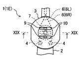
カテーテル用ハンドルのさらに別の実施態様について、図18〜図19を参照して説明する。図18〜図19には、上記に説明したハンドル1Dの変形例を示した。図18は、カテーテル用ハンドルの主要部の平面図を表し、図19は、図18に示したハンドル主要部のXIX−XIX断面図を表す。なお、下記の説明において、上記と重複する部分の説明を省略する。また、図18〜図19では、上記図面と同じ構成要素を同一符号で表している。 Still another embodiment of the catheter handle will be described with reference to FIGS. 18 to 19. 18 to 19 show modified examples of the
図18〜図19に示したハンドル1(1E)は、ワイヤガイド部材7を回転軸方向に移動させる機構がハンドル1Dとは異なる。ハンドル1Dでは、回転軸5をネジから構成し、このネジとナットの嵌合を緩めることでワイヤガイド部材7が回転軸方向に移動可能に形成されるようになっていたが、ハンドル1Eでは、突起18を備えたピン17から回転軸5を構成し、ピン17によってワイヤガイド部材7の回転軸方向の移動を制御している。これについて詳しく説明する。 The handle 1 (1E) shown in FIGS. 18 to 19 is different from the
ハンドル1Eの回転軸5を構成するピン17は、ワイヤガイド部材7とその下側(すなわちワイヤガイド部材7に対して回転軸方向の一方側)の回転盤3Aとハンドル本体2を貫通して設けられている。回転軸方向の他方側に位置する回転盤3Bには凹部16が形成され、ワイヤガイド部材7の溝8を貫通したピン17は、回転盤3Bの凹部16に嵌設されている。ピン17は、ワイヤガイド部材7を回転軸方向の他方側(図19では上側)から押さえる突起18をその側面に備えている。突起18と回転盤3Bの間にはバネ19が設けられ、このバネ19はピン17(突起18)を回転盤3Bから離間させるように作用する。バネ19としては、圧縮コイルバネや皿バネ等を用いることができ、バネ19がピン17を軸に周回して設けられることが好ましい。ハンドル1Eでは、ハンドル本体2を貫通したピン17の下端(回転軸方向の一方側の下端)20が幅広に形成されており、これによりピン17を押しやすくなる。なお、バネ19の代わりに、ハンドル本体2とピン17の下端の間にバネ(圧縮コイルバネや皿バネ等)を設けてもよい。 The
ハンドル1Eでは、ピン17を回転軸方向の一方側(図19では下側)から押すことによって、ワイヤガイド部材7を回転盤3Aから離れるように回転軸方向に移動させることができ、その上でワイヤガイド部材7の凸部9を溝10に沿ってスライドさせることで、ワイヤガイド部材7を回転盤3の平面方向に変位させることができる。ピン17を押さない状態では、バネ19の圧縮回復力によって、突起18を介してワイヤガイド部材7が回転軸方向の他方側(図19では下側)に押さえられ、ワイヤガイド部材7を回転盤3Aに対して固定させることができる。 In the
カテーテル用ハンドルのさらに別の実施態様について、図20〜図22を参照して説明する。図20は、カテーテル用ハンドルの主要部の平面図を表し、図21は、図20に示したハンドル主要部の内部構造の平面図を表し、図22は、図20に示したハンドル主要部のXXII−XXII断面図を表す。なお、下記の説明において、上記と重複する部分の説明を省略する。また、図20〜図22では、上記図面と同じ構成要素を同一符号で表している。 Still another embodiment of the catheter handle will be described with reference to FIGS. 20 shows a plan view of the main part of the handle for a catheter, FIG. 21 shows a plan view of the internal structure of the main part of the handle shown in FIG. 20, and FIG. 22 shows a main part of the handle shown in FIG. XXII-XXII sectional drawing is represented. In the following description, the description of the same parts as above will be omitted. 20 to 22, the same components as those in the above drawings are represented by the same reference numerals.
図20〜図22に示したハンドル1(1F)では、回転盤3がハンドル本体2に対して回転自在に設けられ、ワイヤガイド部材7がハンドル本体2に対して回転不能に設けられている。図22に示すように、回転盤3は、回転軸方向の一方側に位置するハンドル本体2Aに回転軸5で繋がっており、ワイヤガイド部材7は、回転軸方向の他方側に位置するハンドル本体2Bに取り付けられている。ハンドル本体2Bには溝(貫通溝)11が形成され、ワイヤガイド部材7には凸部9が設けられ、凸部9が溝11を貫通している。このようにハンドル本体2とワイヤガイド部材7を構成することにより、ワイヤガイド部材7の凸部9がハンドル1Fの外側に露出し、ハンドル1Fの外側から操作可能となる。そのため、ハンドル1Fを分解しなくても、ワイヤガイド部材7を平面方向に変位させる(すなわち溝11の延在方向に移動させる)ことができる。ハンドル1Fでは、回転盤3の筐体に蓋が設けられていないが、蓋が設けられていてもよい。回転盤3の蓋は、筐体の一部(例えば外縁近傍)のみを覆うように設けられてもよい。凸部9は、ハンドルの外側から手で操作しやすいように、ハンドル本体2Bの溝11を貫通してさらに0.5mm以上延在していることが好ましく、1mm以上延在していることがより好ましい。 In the handle 1 (1F) shown in FIGS. 20 to 22, the
ワイヤガイド部材7は、ハンドルの外側から操作して、回転盤3の回転軸方向に移動可能に形成されていることが好ましい。ハンドル1Fでは、ワイヤガイド部材7の凸部9の側面にネジ山が形成され、凸部9がハンドル本体2Bを貫通し、ハンドル本体2B側からナットで留められている。ナットを緩めることで、ワイヤガイド部材7をハンドル本体2Bから離れるように回転軸方向に移動させることができ、その上で凸部9を溝11に沿ってスライドさせることで、ワイヤガイド部材7を回転盤3の平面方向に変位させることができる。ナットを締めれば、ワイヤガイド部材7をハンドル本体2Bに対して固定することができる。 The
ハンドル1Fでは、回転軸5と重なる位置にハンドル本体2Bの溝11が形成されているが、溝11の位置はこれに限定されず、溝11を2つ以上設けてもよい。また、凸部9をワイヤガイド部材7とハンドル本体2Bを貫通するネジによって形成したり、凸部をピンによって形成し、ナットの代わりにピン留めを用いてもよい。 In the
上記に説明したカテーテル用ハンドルには、ワイヤガイド部材7が1つのみ設けられていたが、ワイヤガイド部材7は複数設けられていてもよい。このようなハンドルの構成例を図23〜図28を参照して説明する。 Although only one
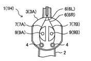
図23〜図25には、ハンドル1Aの変形例として、ワイヤガイド部材7を2つ設けたハンドルの一例を示した。図23は、カテーテル用ハンドルの主要部の平面図を表し、図24は、図23に示したハンドル主要部の内部構造の平面図を表し、図25は、図23に示したハンドル主要部のXXV−XXV断面図を表す。図26〜図28には、ハンドル1Cの変形例として、ワイヤガイド部材7を2つ設けたハンドルの一例を示した。図26は、カテーテル用ハンドルの主要部の平面図を表し、図27は、図26に示したハンドル主要部の内部構造の平面図を表し、図28は、図26に示したハンドル主要部のXXVIII−XXVIII断面図を表す。なお、下記の説明において、上記と重複する部分の説明を省略する。また、図23〜図28では、上記図面と同じ構成要素を同一符号で表している。 23 to 25, an example of a handle provided with two
図23〜図25に示したハンドル1(1G)には、ワイヤガイド部材7として、ハンドルの近位側から見て左側のワイヤ6Lの経路を規定する第1ワイヤガイド部材7Aと、右側のワイヤ6Rの経路を規定する第2ワイヤガイド部材7Bが設けられている。第1ワイヤガイド部材7Aと第2ワイヤガイド部材7Bにはそれぞれ溝(貫通溝)8A,8Bが形成され、第1ワイヤガイド部材7Aと第2ワイヤガイド部材7Bが回転軸方向に重なって設けられ、回転軸5が両方の溝8を貫通している。ハンドル1Gでは、このように第1ワイヤガイド部材7Aと第2ワイヤガイド部材7Bを設けることにより、第1ワイヤガイド部材7Aと第2ワイヤガイド部材7Bが独立して、それぞれの溝8の延在方向に移動することができる。そのため、回転盤3を時計回りに回転させた場合と反時計回りに回転させた場合のいずれにおいても、ワイヤ6Lとワイヤ6Rの牽引長を使用者(術者)が自由に調整でき、回転盤3を回転させた際のチューブ体の遠位側の屈曲の程度を使用者の好みやニーズに応じて連続的に調整することが可能となる。 In the handle 1 (1G) shown in FIGS. 23 to 25, as the
図26〜図28に示したハンドル1(1H)にも、ワイヤガイド部材7として、ハンドルの近位側から見て左側のワイヤ6Lの経路を規定する第1ワイヤガイド部材7Aと、右側のワイヤ6Rの経路を規定する第2ワイヤガイド部材7Bが設けられている。ハンドル1Hでは、第1ワイヤガイド部材7Aと第2ワイヤガイド部材7Bがハンドルの平面方向に並んで配置されている。第1ワイヤガイド部材7Aと第2ワイヤガイド部材7Bにはそれぞれ凸部9A,9Bが設けられ、回転盤3Bにそれぞれの凸部9A,9Bに対応した溝(貫通溝)10A,10Bが形成され、凸部9が溝10を貫通している。ハンドル1Hにおいても、第1ワイヤガイド部材7Aと第2ワイヤガイド部材7Bが独立して、それぞれの溝10の延在方向に移動することができる。さらにハンドル1Hでは、ハンドル1Hの外側から第1ワイヤガイド部材7Aと第2ワイヤガイド部材7Bのそれぞれを平面方向に変位させる(すなわち溝10の延在方向に移動させる)ことができる。そのため、簡単に回転盤3を回転させた際のチューブ体の遠位側の屈曲の程度を調整することができる。 Also in the handle 1 (1H) shown in FIGS. 26 to 28, as the
ハンドル1Hでは、第1ワイヤガイド部材7Aと第2ワイヤガイド部材7Bを平面方向に変位させた際に、各ワイヤガイド部材7の向く方向が適切に制御されるように、各ワイヤガイド部材7と回転盤3Bの対向面が互いに係合していることが好ましい。例えば、ワイヤガイド部材7と回転盤3Bの各対向面の一方に溝10と平行な凸条を形成し、他方に溝10と平行な凹条を形成し、凸条と凹条を係合させればよい。なお、凸条はワイヤガイド部材7の凸部9とは別に設けられ、凹条は回転盤3Bの溝10とは別に設けられる。また、凸条の代わりに凸点を形成してもよい。 In the
上記では、ハンドル1Aとハンドル1Cの変形例としてワイヤガイド部材7を複数設ける態様について説明したが、ワイヤガイド部材7を複数設ける態様はこれに限定されず、例えば、上記に説明した他のハンドルに対しても適用可能である。ワイヤガイド部材7の配置も、回転軸方向に重ねる態様と平面方向に並べる態様のいずれも任意に適用可能であり、適宜組み合わせて実施することもできる。例えば、図26〜図28に示したハンドル1Hにおいて、図23〜図25に示したハンドル1Gの第1ワイヤガイド部材7Aと第2ワイヤガイド部材7Bを設け、第1ワイヤガイド部材7Aと第2ワイヤガイド部材7Bのそれぞれに凸部を設けて回転盤3Bの溝10を貫通させることもできる。ワイヤガイド部材7を複数設ける場合、その数は2つが好ましい。また回転盤3には、ワイヤ6として、左側のワイヤ6Lと右側のワイヤ6Rの両方が配されることが好ましい。 In the above description, a mode in which a plurality of
上記に説明したネジやナットあるいはピンやピン留めは、道具を使わなくても手で操作することができるように、把手などが適宜設けられていてもよい。 The screws and nuts or the pins and the pin fastenings described above may be appropriately provided with a handle or the like so that they can be manually operated without using a tool.
1:カテーテル用ハンドル
2:ハンドル本体
3:回転盤
4:ワイヤ係止部
5:回転軸
6,6L,6R:ワイヤ
7,7A,7B:ワイヤガイド部材
8,8A,8B:ワイヤガイド部材の溝
9,9A,9B:ワイヤガイド部材の凸部
10,10A,10B:回転盤の溝
11:ハンドル本体の溝
12:ハンドル本体の凸部
21:カテーテル
22:チューブ体
23,23A,23B:電極1: Handle for catheter 2: Handle body 3: Rotating plate 4: Wire locking part 5: Rotating
Claims (8)
Translated fromJapanese前記ハンドル本体に対して回転自在に設けられた回転盤と、
前記回転盤の平面方向に変位可能であり、周縁部が前記回転盤の周縁部よりも内側に配置されているワイヤガイド部材と、を有しており、
前記ワイヤガイド部材または前記回転盤には溝が形成され、
前記ワイヤガイド部材が前記溝の延在方向に移動することを特徴とするカテーテル用ハンドル。With the handle body,
A turntable provided rotatably with respect to the handle body,
Whereinit is displaceable in the direction of the plane of theturntable,and possess a wire guidemember peripheral portion is disposed inside the periphery of the rotating disk,and
A groove is formed in the wire guide member or the turntable,
The catheter handle,wherein the wire guide member moves in the extending direction of the groove .
前記カテーテル用ハンドルの遠位側に設けられたチューブ体と、
遠位側が前記チューブ体に固定され、近位側が前記ハンドルに固定されたワイヤを有し、
前記ワイヤが、前記ワイヤガイド部材の外周側に接するように前記回転盤に配されていることを特徴とするカテーテル。A catheter handle according to any one of claims 1 to 7,
A tube body provided on the distal side of the catheter handle,
A wire having a distal side fixed to the tube body and a proximal side fixed to the handle;
The catheter, wherein the wire is arranged on the turntable so as to contact the outer peripheral side of the wire guide member.
Priority Applications (1)
| Application Number | Priority Date | Filing Date | Title |
|---|---|---|---|
| JP2016043925AJP6710066B2 (en) | 2016-03-07 | 2016-03-07 | Catheter handle and catheter having the same |
Applications Claiming Priority (1)
| Application Number | Priority Date | Filing Date | Title |
|---|---|---|---|
| JP2016043925AJP6710066B2 (en) | 2016-03-07 | 2016-03-07 | Catheter handle and catheter having the same |
Publications (2)
| Publication Number | Publication Date |
|---|---|
| JP2017158655A JP2017158655A (en) | 2017-09-14 |
| JP6710066B2true JP6710066B2 (en) | 2020-06-17 |
Family
ID=59854332
Family Applications (1)
| Application Number | Title | Priority Date | Filing Date |
|---|---|---|---|
| JP2016043925AActiveJP6710066B2 (en) | 2016-03-07 | 2016-03-07 | Catheter handle and catheter having the same |
Country Status (1)
| Country | Link |
|---|---|
| JP (1) | JP6710066B2 (en) |
Families Citing this family (1)
| Publication number | Priority date | Publication date | Assignee | Title |
|---|---|---|---|---|
| EP3510914A1 (en)* | 2018-01-15 | 2019-07-17 | Koninklijke Philips N.V. | Device with bendable distal portion and system actuating the distal portion of the device |
Family Cites Families (7)
| Publication number | Priority date | Publication date | Assignee | Title |
|---|---|---|---|---|
| JPS52144177A (en)* | 1976-05-27 | 1977-12-01 | Fuji Photo Optical Co Ltd | Device for stretching operation wire for endscope |
| JPH0761306B2 (en)* | 1987-06-29 | 1995-07-05 | 旭光学工業株式会社 | Endoscope bending operation device |
| JP2000126119A (en)* | 1998-10-28 | 2000-05-09 | Olympus Optical Co Ltd | Endoscof |
| US7717875B2 (en)* | 2004-07-20 | 2010-05-18 | St. Jude Medical, Atrial Fibrillation Division, Inc. | Steerable catheter with hydraulic or pneumatic actuator |
| JP5614848B2 (en)* | 2011-07-12 | 2014-10-29 | 日本ライフライン株式会社 | Catheter handle |
| US9462931B2 (en)* | 2013-03-05 | 2016-10-11 | Boston Scientific Scimed, Inc. | Control system for medical devices and related methods of use |
| JP6210900B2 (en)* | 2014-02-07 | 2017-10-11 | オリンパス株式会社 | Traction balance adjustment mechanism, manipulator and manipulator system |
- 2016
- 2016-03-07JPJP2016043925Apatent/JP6710066B2/enactiveActive
Also Published As
| Publication number | Publication date |
|---|---|
| JP2017158655A (en) | 2017-09-14 |
Similar Documents
| Publication | Publication Date | Title |
|---|---|---|
| US10583272B2 (en) | Steering actuator for deflectable catheter | |
| US9931487B2 (en) | Bidirectional steering control apparatus for a catheter | |
| US11850369B2 (en) | Mapping variable loop catheter handle | |
| US9907570B2 (en) | Steerable medical devices | |
| RU2594817C2 (en) | Control handle for medical device with multiple tension wires | |
| US9498602B2 (en) | Guided intravascular catheter sheath having bi-directional steering assembly | |
| CN102000379B (en) | Band has the conduit of the Multifunctional control handle of rotating mechanism | |
| US20150351610A1 (en) | Endoscope operating apparatus | |
| US20150045696A1 (en) | Steerable dilator | |
| US10076637B2 (en) | Catheter deflection actuator providing mechanical advantage | |
| JP6710066B2 (en) | Catheter handle and catheter having the same | |
| JP6289019B2 (en) | Actuating member and medical device | |
| CN111655322B (en) | Catheter handle and catheter with same | |
| JP2005230471A (en) | Tip deflectable catheter | |
| JP6774764B2 (en) | Catheter handle and catheter with it | |
| US11986157B2 (en) | Braking mechanisms for steerable medical devices and related methods | |
| JP2025073432A (en) | Catheter handle and catheter equipped with same | |
| JP2023091652A (en) | Catheter handle and catheter equipped with the same | |
| JP2025066430A (en) | Handle and catheter equipped with same | |
| WO2020235155A1 (en) | Forceps for endoscope | |
| JP2016002345A (en) | Tip deflection movable catheter | |
| JP2024136427A (en) | Catheter handle and catheter equipped with same | |
| JP2025006325A (en) | Catheter handle and catheter equipped with same | |
| JP2024137618A (en) | Catheter handle and catheter equipped with same | |
| JP2024136429A (en) | Catheter handle and catheter equipped with same |
Legal Events
| Date | Code | Title | Description |
|---|---|---|---|
| A621 | Written request for application examination | Free format text:JAPANESE INTERMEDIATE CODE: A621 Effective date:20190125 | |
| RD02 | Notification of acceptance of power of attorney | Free format text:JAPANESE INTERMEDIATE CODE: A7422 Effective date:20190613 | |
| A977 | Report on retrieval | Free format text:JAPANESE INTERMEDIATE CODE: A971007 Effective date:20191108 | |
| A131 | Notification of reasons for refusal | Free format text:JAPANESE INTERMEDIATE CODE: A131 Effective date:20191119 | |
| A521 | Request for written amendment filed | Free format text:JAPANESE INTERMEDIATE CODE: A523 Effective date:20200115 | |
| TRDD | Decision of grant or rejection written | ||
| A01 | Written decision to grant a patent or to grant a registration (utility model) | Free format text:JAPANESE INTERMEDIATE CODE: A01 Effective date:20200519 | |
| A61 | First payment of annual fees (during grant procedure) | Free format text:JAPANESE INTERMEDIATE CODE: A61 Effective date:20200526 | |
| R150 | Certificate of patent or registration of utility model | Ref document number:6710066 Country of ref document:JP Free format text:JAPANESE INTERMEDIATE CODE: R150 | |
| R250 | Receipt of annual fees | Free format text:JAPANESE INTERMEDIATE CODE: R250 | |
| R250 | Receipt of annual fees | Free format text:JAPANESE INTERMEDIATE CODE: R250 | |
| R250 | Receipt of annual fees | Free format text:JAPANESE INTERMEDIATE CODE: R250 |