JP6709628B2 - Input device and display device - Google Patents
Input device and display deviceDownload PDFInfo
- Publication number
- JP6709628B2 JP6709628B2JP2016018347AJP2016018347AJP6709628B2JP 6709628 B2JP6709628 B2JP 6709628B2JP 2016018347 AJP2016018347 AJP 2016018347AJP 2016018347 AJP2016018347 AJP 2016018347AJP 6709628 B2JP6709628 B2JP 6709628B2
- Authority
- JP
- Japan
- Prior art keywords
- operation unit
- unit
- input device
- region
- diaphragm
- Prior art date
- Legal status (The legal status is an assumption and is not a legal conclusion. Google has not performed a legal analysis and makes no representation as to the accuracy of the status listed.)
- Active
Links
Images


Landscapes
- User Interface Of Digital Computer (AREA)
Description
Translated fromJapanese本発明は、入力装置および表示装置に関する。 The present invention relates to an input device and a display device.
従来、操作部の操作面に対するユーザの接触操作を検出することでユーザからの入力操作を受け付けると共に操作部を振動させることでユーザに触感を与えることが可能な入力装置が知られている。 2. Description of the Related Art Conventionally, there is known an input device capable of receiving a user's input operation by detecting a user's touch operation on the operation surface of the operation unit and giving a touch to the user by vibrating the operation unit.
例えば、タッチスクリーンパネルに装着される画像表示部に装着されて振動する剛性部材が、振動を発生させる手段、質量を増加させる質量体、および振動変位を増加させる弾性部材を含む、タッチスクリーン装置が開示されている(例えば、特許文献1参照)。 For example, a touch screen device in which a rigid member mounted on an image display unit mounted on a touch screen panel and vibrating includes means for generating vibration, a mass body for increasing mass, and an elastic member for increasing vibration displacement is provided. It is disclosed (for example, see Patent Document 1).
しかしながら、従来の入力装置においては、例えば、操作部を構成する振動板の厚さおよび材料物性に依存して、操作部を振動させる際にノイズが発生する場合がある。 However, in the conventional input device, noise may occur when the operating unit is vibrated, depending on, for example, the thickness and material properties of the diaphragm that constitutes the operating unit.
ここで、従来の入力装置において、操作部を振動させる際に発生するノイズを低減するために、操作部を構成する振動板の厚さを低減することが考えられる。 Here, in the conventional input device, it is conceivable to reduce the thickness of the diaphragm forming the operation unit in order to reduce noise generated when the operation unit is vibrated.
しかしながら、従来の入力装置において、操作部を構成する振動板の厚さを低減すると、操作部の振動が不安定になる場合がある。その結果、操作部の操作面に対する接触操作を行うユーザに適切な触感を与えられない場合がある。 However, in the conventional input device, if the thickness of the diaphragm that constitutes the operation unit is reduced, the vibration of the operation unit may become unstable. As a result, it may not be possible to give an appropriate tactile sensation to a user who performs a touch operation on the operation surface of the operation unit.
本発明は、上記に鑑みてなされたものであって、操作部を振動させる際に発生するノイズを低減すると共に操作部の振動を安定化させることが可能な入力装置および表示装置を提供することを目的とする。 The present invention has been made in view of the above, and provides an input device and a display device capable of reducing noise generated when vibrating an operation unit and stabilizing the vibration of the operation unit. With the goal.
上記課題を解決し、目的を達成するために、本発明の入力装置は、操作部と、検出部と、振動素子と、振動制御部と、を備える。操作部は、操作面を有する。検出部は、操作面に対するユーザの接触操作を検出する。振動素子は、前記操作部を振動させる。振動制御部は、検出部によって検出された接触操作に基づいて振動素子の振動を制御する。また、操作部は、操作面を有する第1の領域と、第1の領域の周辺に設けられ第1の領域の剛性よりも高い剛性を備える第2の領域と、を有する。 In order to solve the above problems and achieve the object, an input device of the present invention includes an operation unit, a detection unit, a vibration element, and a vibration control unit. The operation unit has an operation surface. The detection unit detects a user's touch operation on the operation surface. The vibrating element vibrates the operation unit. The vibration control unit controls the vibration of the vibration element based on the contact operation detected by the detection unit. In addition, the operation unit has a first region having an operation surface and a second region provided around the first region and having a rigidity higher than that of the first region.
本発明によれば、操作部を振動させる際に発生するノイズを低減すると共に操作部の振動を安定化させることが可能な入力装置および表示装置を提供することができる。 According to the present invention, it is possible to provide an input device and a display device that can reduce noise generated when vibrating the operation unit and stabilize the vibration of the operation unit.
以下に、本発明の実施形態に係る入力装置および表示装置を図面に基づいて詳細に説明する。なお、以下に示す実施形態によりこの発明が限定されるものではない。 Hereinafter, an input device and a display device according to an embodiment of the present invention will be described in detail with reference to the drawings. The present invention is not limited to the embodiments described below.
[1.入力装置の概要]
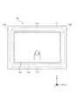
まず、本発明の実施形態に係る入力装置の概要について図1を用いて説明する。図1は、本発明の実施形態に係る入力装置10の概要を説明する図である。[1. Input device overview]
First, the outline of the input device according to the embodiment of the present invention will be described with reference to FIG. FIG. 1 is a diagram illustrating an outline of an
図1には、X軸、Y軸、およびZ軸を含む3次元の直交座標系が示されている。かかる3次元の直交座標系は、他の図面でも示される場合がある。図1に示すZ軸の正方向および負方向は、それぞれ、図1の紙面に対して手前側および奥側に対応する。 FIG. 1 shows a three-dimensional orthogonal coordinate system including an X axis, a Y axis, and a Z axis. Such a three-dimensional rectangular coordinate system may be shown in other drawings. The positive and negative directions of the Z axis shown in FIG. 1 correspond to the front side and the back side with respect to the paper surface of FIG. 1, respectively.
入力装置10は、例えば、カーナビゲーションシステムに搭載される車載用のタッチパネルに含まれる位置入力装置である。入力装置10は、操作部11と、第1の振動素子13aと、第2の振動素子13bとを備える。 The
操作部11は、操作面11aを有する。操作部11は、例えば、タッチパッドである。操作面11aは、操作部11の略中央に設けられる略矩形の面である。 The
第1の振動素子13aおよび第2の振動素子13bの各々は、操作部11を振動させる。第1の振動素子13aおよび第2の振動素子13bの各々は、例えば、圧電アクチュエータである。第1の振動素子13aおよび第2の振動素子13bは、操作面11aを挟むように、かつ、操作面11aの略矩形の短辺方向、すなわち、Y方向に延びるように、設けられる。 Each of the first vibrating
例えば、ユーザの指が、操作面11aに対して接触操作を行うと、入力装置10は、操作面11aに対するユーザの接触操作を検出する。それによって、入力装置10は、ユーザからの入力操作を受け付ける。 For example, when the user's finger performs a contact operation on the
また、入力装置10は、検出されたユーザの接触操作に基づいて第1の振動素子13aおよび第2の振動素子13bの振動を制御する。それによって、入力装置10は、ユーザの接触操作に応じて、操作部11の振動を制御することができる。その結果、入力装置10は、ユーザの接触操作に応じた触感をユーザに与えることができる。 Further, the
操作部11は、さらに、第1の領域11bと、第2の領域11cおよび11dとを有する。第1の領域11bは、操作面11aを有する。第2の領域11cおよび11dの各々は、第1の領域11bの周辺に設けられ第1の領域11bの剛性よりも高い剛性を備える。 The
第1の領域11bは、たとえば、操作面11aを含み、第1の振動素子13aと第2の振動素子13bとの間に挟まれた略矩形の領域である。第1の領域11bは、第1の振動素子13aおよび第2の振動素子13bによって振動させられる。 The
第2の領域11cおよび11dの各々は、第1の領域11bの周辺に設けられた略矩形の領域である。第2の領域11cおよび11dの各々の略矩形の長辺は、第1の領域の略矩形の長辺方向と略平行な方向、すなわち、X軸方向に設けられる。 Each of the
ここで、操作部11を振動させる際に発生するノイズを低減するために操作部11を構成する振動板の厚さを低減する場合には、操作部11の剛性が低減される。この場合においても、操作部11は、第1の領域11bの剛性よりも高い剛性を備える第2の領域11cおよび11dを備えることによって、操作部11に剛性を付与することが可能となる。それによって、操作部11の振動を安定化させることが可能となる。 Here, in the case of reducing the thickness of the diaphragm forming the
このように、入力装置10によれば、操作部11を振動させる際に発生するノイズを低減すると共に操作部11の振動を安定化させることが可能となる。 As described above, according to the
次に、入力装置10を含む本発明の実施形態に係る表示装置について図2を用いて説明する。図2は、本発明の実施形態に係る表示装置1の構成を説明する図である。 Next, the display device including the
[2.表示装置1]
表示装置1は、例えば、車両に搭載されるカーナビゲーションシステム用のモニター、スマートフォンまたはタブレット端末に用いられるタッチパネルである。表示装置1は、入力装置10と、表示部20とを備える。[2. Display device 1]
The display device 1 is, for example, a monitor for a car navigation system mounted on a vehicle, a touch panel used for a smartphone or a tablet terminal. The display device 1 includes an
[2.1.入力装置10]
入力装置10は、例えば、タッチパネルに含まれる位置入力装置である。入力装置10は、ユーザからの入力操作を受け付け、ユーザからの入力操作に応じた信号を表示部20へ出力する。入力装置10は、操作部11と、制御部12と、振動部13と、記憶部14とを備える。[2.1. Input device 10]
The
[2.1.1.操作部11]
操作部11は、例えば、タッチパネルに用いられるタッチパッドである。タッチパッドは、例えば、静電容量の変化によってユーザの接触操作を受け付ける平板状のセンサーを有する。[2.1.1. Operation part 11]
The
操作部11は、ユーザの接触操作を受け付ける操作面11aを有する。例えば、ユーザが指またはタッチペンのようなポインティングデバイスを用いて操作面11a上で接触操作を行うと、操作部11は、操作面11aに対するユーザの接触操作に応じた信号を制御部12へ出力する。なお、かかる操作部11の構成については、別途詳述する。 The
[2.1.2.制御部12]
制御部12は、入力装置10に含まれる各部を制御する。制御部12は、操作部11の操作面11aを介して受け付けたユーザの接触操作に応じた信号に基づいて、記憶部14に対するデータの読み出しまたは書き込みを実行し、信号を振動部13および表示部20に出力する。制御部12は、例えば、コンピュータのCPU(Central Processing Unit)である。制御部12は、検出部12aと、振動制御部12bと、表示制御部12cとを備える。[2.1.2. Controller 12]
The
[2.1.2.1.検出部12a]
検出部12aは、操作部11から出力された信号に基づいて、操作部11の操作面11aに対するユーザの接触操作を検出する。検出部12aは、操作面11aに対するユーザの接触操作を検出すると、ユーザの接触操作の検出結果に応じた信号を振動制御部12bおよび表示制御部12cへ出力する。[2.1.2.1.
The
[2.1.2.2.振動制御部12b]
振動制御部12bは、検出部12aから出力された信号、すなわち、検出部12aによって検出された接触操作に基づいて、振動部13に含まれる第1の振動素子13aおよび第2の振動素子13bの振動を制御する。[2.1.2.2.
The
振動制御部12bは、第1の振動素子13aおよび第2の振動素子13bの振動に対応する電圧信号を振動部13へ出力する。 The
振動制御部12bは、例えば、超音波周波数帯で第1の振動素子13aおよび第2の振動素子13bを振動させることができる。この場合には、ユーザの指と操作面11aとの間に空気層が形成され、ユーザの指と操作面11aとの間の摩擦力が低減する。その結果、ユーザは、ユーザの指と操作面11aとの間の低減された摩擦力によって、操作面11aのより滑らかな触感を得ることが可能となる。 The
例えば、検出部12aが、操作面11aに対するユーザの指の押圧または移動を検出すると、振動制御部12bは、超音波周波数帯で第1の振動素子13aおよび第2の振動素子13bの振動を制御することができる。それによって、ユーザの指と操作面11aとの間の摩擦力を制御することができる。その結果、入力装置10は、操作面11aに対するユーザの触感を制御することが可能となる。 For example, when the
なお、振動制御部12bは、超音波周波数帯で第1の振動素子13aおよび第2の振動素子13bを振動させるとしたが、振動制御部12bは、超音波周波数帯よりも低い周波数で第1の振動素子13aおよび第2の振動素子13bを振動させてもよい。この場合には、入力装置10は、ユーザに振動の触感を与えることが可能となる。 Although the
[2.1.2.3.表示制御部12c]
表示制御部12cは、検出部12aから出力された信号に基づいて、表示部20に表示させる情報に対応する信号を出力する。[2.1.2.3.
The
[2.1.3.振動部13]
振動部13は、操作部11を振動させる少なくとも1つの振動素子、例えば、第1の振動素子13aおよび第2の振動素子13bを備える。[2.1.3. Vibration part 13]
The vibrating
第1の振動素子13aおよび第2の振動素子13bの各々は、例えば、圧電素子(ピエゾ素子)で構成された圧電アクチュエータである。この場合には、第1の振動素子13aおよび第2の振動素子13bの各々は、制御部12から出力された電圧信号に基づいて伸縮することで操作部11を振動させる。 Each of the first vibrating
第1の振動素子13aおよび第2の振動素子13bの各々は、操作部11と接触するように設けられる。第1の振動素子13aおよび第2の振動素子13bは、第1の振動素子13aおよび第2の振動素子13bによって発生させられる波が重なり合って定常波を形成するように設けられる。例えば、第1の振動素子13aおよび第2の振動素子13bの各々は、図1に示すように、操作面11aを挟むように、かつ、操作部11を振動させる波の伝播方向と垂直な方向に延びるように、設けられる。 Each of the first vibrating
振動部13が、操作面11aを挟むように設けられた第1の振動素子13aおよび第2の振動素子13bを含むとしたが、振動部13に含まれる振動素子の個数および配置は、特に限定されない。例えば、振動部13に含まれる振動素子の個数は、一個であってもよい。また、例えば、操作面11aの両端部の各々に二個の振動素子を配置してもよく、操作面11aの片方の端部のみに二個の振動素子を配置してもよい。 The vibrating
また、第1の振動素子13aおよび第2の振動素子13bの各々が圧電アクチュエータであるとしたが、第1の振動素子13aおよび第2の振動素子13bの各々は、圧電アクチュエータに限定されない。例えば、第1の振動素子13aおよび第2の振動素子13bの各々は、超音波周波数で操作部11を振動させることが可能な素子であってもよい。 Further, although each of the first vibrating
[2.1.4.記憶部14]
記憶部14は、入力装置10に含まれる各部によって実行される処理に必要な情報および/または入力装置10に含まれる各部によって実行される処理の結果を記憶する。[2.1.4. Storage unit 14]
The
記憶部14は、例えば、ユーザの接触操作に関するデータならびにユーザの接触操作に関するデータと関連付けられた振動素子の制御データおよび表示部20に表示する情報を記憶する。表示部20に表示する情報は、例えば、地図など車両のナビゲーションを行うための画像またはテレビもしくはインターネットの動画もしくは静止画のような画像データであってもよい。 The
記憶部14は、例えば、RAM(Random Access Memory)、ROM(Read Only Memory)、もしくはフラッシュメモリのような半導体メモリ素子、ハードディスク、または光ディスクのような記憶デバイスである。 The
[2.2.表示部20]
表示部20は、表示制御部12cから出力された信号に基づいて、すなわち、入力装置10に含まれる検出部12aによって検出された接触操作に基づいて、情報を表示する。表示部20は、たとえば液晶ディスプレイである。表示部20は、ユーザに情報を提示する。[2.2. Display unit 20]
The
図3は、表示部20の第1の配置例を説明する図である。図3に示す例においては、表示部20は、入力装置10と一体的に設けられる。入力装置10および表示部20は、入力装置10に含まれる操作部11の操作面11aが表示部20の表示領域と対向するように、配置される。操作部11の操作面11aは、光透過性の材料で形成される。この場合には、ユーザは、表示部20の表示領域に表示された情報を、操作面11aを介して視認することができる。 FIG. 3 is a diagram illustrating a first arrangement example of the
図4は、表示部20の第2の配置例を説明する図である。図4に示す例においては、表示部20は、入力装置10と別個に設けられる。入力装置10は、表示部20と有線または無線で通信するように構成される。入力装置10および表示部20は、入力装置10に含まれる操作部11の操作面11aにおける特定の位置が、表示部20の表示領域における特定の位置と対応するように、構成される。 FIG. 4 is a diagram illustrating a second arrangement example of the
[3.1.操作部11の第1の構成例]
次に、図1に示す操作部11の第1の構成例について図5Aおよび図5Bを用いて説明する。図5Aは、操作部11の第1の構成例を説明する平面図である。図5Bは、操作部11の第1の構成例を説明する側面図である。図5Aに示すZ軸の正方向および負方向は、それぞれ、図5Aの紙面に対して奥側および手前側に対応する。[3.1. First Configuration Example of Operation Unit 11]
Next, a first configuration example of the
図5Aおよび図5Bに示す操作部11の構成要素のうち、図1に示す操作部11の構成要素と同一または類似の構成要素については、図1に示す符号と同一の符号を付与し、その説明を省略または簡略化することにする。また、図5Aおよび図5Bに示す例では、説明の便宜上、第1の振動素子13aおよび第2の振動素子13bも図示している。 Of the components of the
図5Aおよび図5Bに示す操作部11は、操作面11aを有する。第1の振動素子13aおよび第2の振動素子13bの各々は、操作部11を振動させる。第1の振動素子13aおよび第2の振動素子13bによって発生させられた操作部11を振動させる波は、操作面11aの略矩形の長辺方向、すなわち、X軸方向に伝播する。 The
操作部11は、第1の領域11bと、第2の領域11cおよび11dとを有する。第1の領域11bは、操作面11aを有する。 The
第2の領域11cおよび11dの各々は、第1の領域11bの周辺に設けられ第1の領域11bの剛性よりも高い剛性を備える。これにより、操作部11を振動させる際に発生するノイズを低減すると共に操作部11の振動を安定化させることが可能となる。 Each of the
図5Aおよび図5Bに示す操作部11においては、第2の領域11cおよび11dの各々は、操作部11を振動させる波の伝播方向に沿って延びる形状を有する。例えば、第2の領域11cおよび11dの各々は、第1の領域11bを振動させる波の伝播方向、すなわち、X軸方向に沿って延びる略矩形の形状を有する。 In
この場合には、第2の領域11cおよび11dが、操作部11を振動させる波の伝播を阻害することを防止することが可能となる。それによって、操作部11の振動をより安定化させることが可能となる。 In this case, it is possible to prevent the
なお、第2の領域11cおよび11dの各々のサイズは、振動板11eの振動を安定化させるように振動板11eに剛性を付与することができる限り、特に限定されない。例えば、X軸方向に沿った第2の領域11cおよび11dの各々の長さは、第1の振動素子13aと第2の振動素子13bとの間の距離よりも大きくても小さくてもよい。 The size of each of the
ただし、第2の領域11cおよび11dの各々は、一個の領域であることが好ましい。この場合には、第2の領域11cおよび11dの各々をより簡便に操作部11に配置することが可能となる。 However, each of the
図5Aおよび図5Bに示す操作部11においては、第2の領域11cおよび11dは、第1の領域11bを間に挟む位置に設けられる。例えば、第2の領域11cおよび11dが第1の領域11bに対して略対称的に設けられる。 In
この場合には、第2の領域11cおよび11dは、操作部11に対して略対称的に剛性を付与することが可能となる。それによって、操作部11の振動をより安定化させることが可能となる。 In this case, the
図5Aおよび図5Bに示す操作部11において、操作部11は、操作面11aを有する振動板11eを備える。第1の振動素子13aおよび第2の振動素子13bは、振動板11eを振動させる。 In the
第1の領域11bは、振動板11e上の領域である。第2の領域11cは、振動板11eの一側面に第1の補強部材101aを貼り付けることによって形成される。第2の領域11dは、振動板11eの一側面に第2の補強部材101bを貼り付けることによって形成される。 The
第1の補強部材101aおよび第2の補強部材101bの各々は、例えば、X軸方向に長辺を有する略短冊状の部材である。第1の補強部材101aおよび第2の補強部材101bの各々は、例えば、接着剤または粘着テープによって振動板11eの一側面に貼り付けられる。 Each of the
この場合には、振動板11eの一面に第1の補強部材101aおよび第2の補強部材101bを貼り付けることによって、第1の領域11bの剛性よりも高い剛性を備える第2の領域11cおよび11dを簡便に形成することができる。 In this case, by attaching the first reinforcing
第1の補強部材101aおよび第2の補強部材101bの各々の材質は、特に限定されない。第1の補強部材101aおよび第2の補強部材101bの各々の材質は、例えば、ステンレス鋼のような金属、ガラス、またはセラミックであってもよい。 The material of each of the first reinforcing
ただし、操作部11が、静電容量の変化によって位置検出を行うタッチパッドである場合等には、第1の補強部材101aおよび第2の補強部材101bの各々の材質は、好ましくは、導電体である金属ではなく、ガラスまたはセラミックである。 However, when the
この場合には、第1の補強部材101aおよび第2の補強部材101bが、操作面11aに対するユーザの接触操作を受け付ける操作部11の動作に及ぼす影響を低減することができる。 In this case, it is possible to reduce the influence of the first reinforcing
振動板11eの材質としては、例えば、ガラス、有機ガラス、またはポリカーボネートのような透過性を有する材料を用いてもよい。しかしながら、振動板11eの材質は、透過性を有する材料に限定されない。振動板11eの材質としては、例えば、ポリ塩化ビニル樹脂、シリコーン樹脂、またはシリコーンゴムを用いてもよい。 As a material of the
[3.2.操作部11の第2の構成例]
次に、図1に示す操作部11の第2の構成例について図6Aおよび図6Bを用いて説明する。図6Aは、操作部11の第2の構成例を説明する平面図である。図6Bは、操作部11の第2の構成例を説明する側面図である。また、図5Aおよび図5Bに示す例と同様に、図6Aおよび図6Bに示す例では、説明の便宜上、第1の振動素子13aおよび第2の振動素子13bも図示している。[3.2. Second Configuration Example of Operation Unit 11]
Next, a second configuration example of the
図6Aおよび図6Bに示す操作部11の構成要素のうち、図5Aおよび図5Bに示す操作部11の構成要素と同一または類似の構成要素については、図5Aおよび図5Bに示す符号と同一の符号を付与し、その説明を省略または簡略化することにする。図6Aおよび図6Bに示す操作部11は、操作部11に含まれる第2の領域11cおよび11dの構成の点で、図5Aおよび図5Bに示す操作部11と相違する。 Of the components of the
図6Aおよび図6Bに示す操作部11は、操作面11aを有する振動板11eを備え、第2の領域11cおよび11dの各々における振動板11eの厚さは、第1の領域11bにおける振動板11eの厚さよりも大きい。例えば、振動板11eは、第2の領域11cにおける第1の凸部102aおよび第2の領域11dにおける第2の凸部102bを有する。 The
このように、第2の領域11cは、第1の領域11bにおける振動板11eの厚さより大きい厚さを有する第1の凸部102aによって形成される。第2の領域11dは、第1の領域11bにおける振動板11eの厚さより大きい厚さを有する第2の凸部102bによって形成される。 Thus, the
この場合には、振動板11eとして、第2の領域11cおよび11dの各々を第1の領域11bと一体的に形成することができる。例えば、振動板11eの少なくとも一面に補強部材を設けることなく、操作部11に第2の領域11cおよび11dを形成することができる。 In this case, each of the
第1の凸部102aおよび第2の凸部102bを有する振動板11eを形成するために、例えば、研削、研磨、機械的エッチング、または化学的エッチングの手段によって、振動板11eを形成するための平板を加工してもよい。例えば、振動板11eを形成するための平板を、第1の凸部102aおよび第2の凸部102bに対応する部分以外の部分の厚さ、例えば、中央部分の厚さ、を低減するように、加工してもよい。 In order to form the
なお、操作部11の第2の構成例における振動板11eの材質としては、操作部11の第1の構成例における振動板11eの材質を用いることができる。 As the material of the
[3.3.操作部11の第3の構成例]
次に、図1に示す操作部11の第3の構成例について図7Aおよび図7Bを用いて説明する。図7Aは、操作部11の第3の構成例を説明する平面図である。図7Bは、操作部11の第3の構成例を説明する側面図である。また、図5Aおよび図5Bに示す例と同様に、図7Aおよび図7Bに示す例では、説明の便宜上、第1の振動素子13aおよび第2の振動素子13bも図示している。[3.3. Third Configuration Example of Operation Unit 11]
Next, a third configuration example of the
図7Aおよび図7Bに示す操作部11の構成要素のうち、図5Aおよび図5Bに示す操作部11の構成要素と同一または類似の構成要素については、図5Aおよび図5Bに示す符号と同一の符号を付与し、その説明を省略または簡略化することにする。図7Aおよび図7Bに示す操作部11は、操作部11に含まれる第2の領域11cおよび11dの構成の点で、図5Aおよび図5Bに示す操作部11と相違する。 Of the components of the
図7Aおよび図7Bに示す操作部11は、操作面11aを有する振動板11eを備え、第2の領域11cは、振動板11eの上面、側面、および下面に第1の補強部材103aをはめ込むことによって形成される。第2の領域11dは、振動板11eの上面、側面、および下面に第2の補強部材103bをはめ込むことによって形成される。 The
第1の補強部材103aおよび第2の補強部材103bの各々は、図7Bに示すようにYZ平面において略コの字型の断面を有する部材である。第1の補強部材103aおよび第2の補強部材103bの各々は、略コの字型の断面を有する部材の凹部に振動板11eの周辺部分を挿入することによって、振動板11eの上面、側面、および下面にはめ込まれる。 Each of the first reinforcing
なお、操作部11の第3の構成例における振動板11e、第1の補強部材103aおよび第2の補強部材103bの材質としては、操作部11の第1の構成例における振動板11e、第1の補強部材103aおよび第2の補強部材103bの材質を用いることができる。 The materials of the
この場合には、振動板11eの上面、側面、および下面に第1の補強部材103aおよび第2の補強部材103bをはめ込むことによって、第1の領域11bの剛性よりも高い剛性を備える第2の領域11cおよび11dをさらに簡便に形成することができる。 In this case, by fitting the first reinforcing
なお、操作部11の第2の領域11cおよび11dの各々の構成は、上述したものに限定されるものではない。例えば、第2の領域11cおよび11dの各々は、振動板11eの表面に凹部を設けると共に振動板11eの表面に設けられた凹部に補強部材を埋め込むことによって形成されてもよい。この場合には、振動板11eの表面に設けられた凹部によって補強部材をより容易に位置決めすることが可能となる。 The configuration of each of the
さらなる効果や変形例は、当業者によって容易に導き出すことができる。このため、本発明のより広範な態様は、以上のように表しかつ記述した特定の詳細および代表的な実施形態に限定されるものではない。したがって、添付の特許請求の範囲およびその均等物によって定義される総括的な発明の概念の精神または範囲から逸脱することなく、様々な変更が可能である。 Further effects and modifications can be easily derived by those skilled in the art. Therefore, the broader aspects of the present invention are not limited to the specific details and representative embodiments shown and described above. Accordingly, various modifications may be made without departing from the spirit or scope of the general inventive concept defined by the appended claims and their equivalents.
1 表示装置
10 入力装置
20 表示部
11 操作部
11a 操作面
11b 第1の領域
11c,11d 第2の領域
11e 振動板
12 制御部
12a 検出部
12b 振動制御部
12c 表示制御部
13 振動部
13a 第1の振動素子
13b 第2の振動素子
14 記憶部
101a,103a 第1の補強部材
101b,103b 第2の補強部材
102a 第1の凸部
102b 第2の凸部DESCRIPTION OF SYMBOLS 1
Claims (5)
Translated fromJapanese前記操作面に対するユーザの接触操作を検出する検出部と、
前記操作部を振動させる振動素子と、
前記検出部によって検出された接触操作に基づいて前記振動素子の振動を制御する振動制御部と、を備え、
前記操作部は、
前記操作面を有する第1の領域と、前記第1の領域の周辺に設けられ前記第1の領域の剛性よりも高い剛性を備える第2の領域と、を有すると共に、
前記振動素子は、前記第1の領域を間に挟む位置にそれぞれ設けられ、
前記第2の領域は、前記第1の領域を間に挟む位置にそれぞれ設けられ、前記操作部を振動させる波の伝播方向に交差する方向に沿って延びることなく前記操作部を振動させる波の伝播方向に沿って延びる形状を有する一様な剛性の領域である
ことを特徴とする入力装置。An operation unit having an operation surface,
A detection unit that detects a user's touch operation on the operation surface,
A vibrating element that vibrates the operation unit,
A vibration control unit that controls the vibration of the vibrating element based on a contact operation detected by the detection unit;
The operation unit is
While having a first area having the operation surface and a second area provided around the first area and having a rigidity higher than the rigidity of the first area,
The vibrating elements are provided at positions sandwiching the first region,
The second regions are respectively provided at positions sandwiching the first region, and the second region does not extend along a direction intersecting a propagation direction of a wave that vibrates the operation unit, and the second region vibrates the operation unit. An input device,which is a region of uniform rigidity having a shape extending along a propagation direction.
前記操作面を有する振動板を備え、
前記第2の領域は、
前記振動板の少なくとも一面に補強部材を設けることによって形成される
ことを特徴とする請求項1に記載の入力装置。The operation unit is
A diaphragm having the operation surface,
The second area is
The input device according to claim 1, wherein the input device is formed by providing a reinforcing member on at least one surface of the diaphragm.
ステンレス鋼、ガラス、またはセラミックである
ことを特徴とする請求項2に記載の入力装置。The material of the reinforcing member is
The input device according to claim 2, wherein the input device is stainless steel, glass, or ceramic.
前記操作面を有する振動板を備え、
前記第2の領域における前記振動板の厚さは、前記第1の領域における前記振動板の厚さよりも大きい
ことを特徴とする請求項1に記載の入力装置。The operation unit is
A diaphragm having the operation surface,
The input device according to claim 1, wherein a thickness of the diaphragm in the second region is larger than a thickness of the diaphragm in the first region.
前記入力装置に含まれる前記検出部によって検出された接触操作に基づいて情報を表示する表示部と
を備えることを特徴とする表示装置。The input device according to any one of claims 1 to 4,
A display unit that displays information based on a touch operation detected by the detection unit included in the input device.
Priority Applications (2)
| Application Number | Priority Date | Filing Date | Title |
|---|---|---|---|
| JP2016018347AJP6709628B2 (en) | 2016-02-02 | 2016-02-02 | Input device and display device |
| US15/408,809US20170220197A1 (en) | 2016-02-02 | 2017-01-18 | Input device, system, method of manufacturing input device and display device |
Applications Claiming Priority (1)
| Application Number | Priority Date | Filing Date | Title |
|---|---|---|---|
| JP2016018347AJP6709628B2 (en) | 2016-02-02 | 2016-02-02 | Input device and display device |
Publications (2)
| Publication Number | Publication Date |
|---|---|
| JP2017138735A JP2017138735A (en) | 2017-08-10 |
| JP6709628B2true JP6709628B2 (en) | 2020-06-17 |
Family
ID=59565041
Family Applications (1)
| Application Number | Title | Priority Date | Filing Date |
|---|---|---|---|
| JP2016018347AActiveJP6709628B2 (en) | 2016-02-02 | 2016-02-02 | Input device and display device |
Country Status (1)
| Country | Link |
|---|---|
| JP (1) | JP6709628B2 (en) |
Families Citing this family (1)
| Publication number | Priority date | Publication date | Assignee | Title |
|---|---|---|---|---|
| JP7094088B2 (en)* | 2017-10-19 | 2022-07-01 | 株式会社デンソーテン | Operation input device |
Family Cites Families (6)
| Publication number | Priority date | Publication date | Assignee | Title |
|---|---|---|---|---|
| JP2007065798A (en)* | 2005-08-29 | 2007-03-15 | Seiko Epson Corp | Touch panel device |
| US20100207895A1 (en)* | 2009-02-16 | 2010-08-19 | Samsung Electro-Mechanics Co., Ltd. | Tactile interface device and method for controlling the same |
| JP5962907B2 (en)* | 2011-07-06 | 2016-08-03 | パナソニックIpマネジメント株式会社 | Electronics |
| FR2985331B1 (en)* | 2011-12-30 | 2014-04-25 | Dav | HAPTIC RETURN CONTROL DEVICE |
| JP5812926B2 (en)* | 2012-04-12 | 2015-11-17 | 京セラ株式会社 | Electronics |
| JP6048188B2 (en)* | 2013-02-08 | 2016-12-21 | 株式会社デンソー | Touch panel device |
- 2016
- 2016-02-02JPJP2016018347Apatent/JP6709628B2/enactiveActive
Also Published As
| Publication number | Publication date |
|---|---|
| JP2017138735A (en) | 2017-08-10 |
Similar Documents
| Publication | Publication Date | Title |
|---|---|---|
| US20170220197A1 (en) | Input device, system, method of manufacturing input device and display device | |
| JP6078935B2 (en) | Electronics | |
| JP6111315B1 (en) | Tactile presentation device | |
| CN103518174B (en) | Electronic equipment | |
| CN103970338B (en) | Touch panel supporter | |
| KR20180108465A (en) | System for providing sensor and actuation functionality for touch input device | |
| JP7038552B2 (en) | Operation input device and touch panel | |
| JP2012190452A (en) | Electronic device | |
| US20190107889A1 (en) | Input device | |
| JP2012190450A (en) | Electronic device | |
| JP2006227712A (en) | Electronic equipment | |
| WO2017090449A1 (en) | Tactile sense presentation device and tactile sense presentation method | |
| JP7141215B2 (en) | Operation input device and touch panel | |
| JP2018206275A (en) | Input device | |
| JP5611078B2 (en) | Electronics | |
| JP5767995B2 (en) | Electronics | |
| WO2015146116A1 (en) | Vibration module and electronic device | |
| JP5777552B2 (en) | Electronics | |
| JP6709628B2 (en) | Input device and display device | |
| JP5530026B2 (en) | Electronics | |
| US20180348873A1 (en) | Input device | |
| JP6613153B2 (en) | Tactile presentation device | |
| JP2019021144A (en) | Control device, control method, and input device | |
| US10725547B2 (en) | Input device | |
| JP5731227B2 (en) | Electronics |
Legal Events
| Date | Code | Title | Description |
|---|---|---|---|
| A621 | Written request for application examination | Free format text:JAPANESE INTERMEDIATE CODE: A621 Effective date:20190201 | |
| A977 | Report on retrieval | Free format text:JAPANESE INTERMEDIATE CODE: A971007 Effective date:20190927 | |
| A131 | Notification of reasons for refusal | Free format text:JAPANESE INTERMEDIATE CODE: A131 Effective date:20191105 | |
| A521 | Request for written amendment filed | Free format text:JAPANESE INTERMEDIATE CODE: A523 Effective date:20191220 | |
| A131 | Notification of reasons for refusal | Free format text:JAPANESE INTERMEDIATE CODE: A131 Effective date:20200114 | |
| A521 | Request for written amendment filed | Free format text:JAPANESE INTERMEDIATE CODE: A523 Effective date:20200302 | |
| TRDD | Decision of grant or rejection written | ||
| A01 | Written decision to grant a patent or to grant a registration (utility model) | Free format text:JAPANESE INTERMEDIATE CODE: A01 Effective date:20200428 | |
| A61 | First payment of annual fees (during grant procedure) | Free format text:JAPANESE INTERMEDIATE CODE: A61 Effective date:20200525 | |
| R150 | Certificate of patent or registration of utility model | Ref document number:6709628 Country of ref document:JP Free format text:JAPANESE INTERMEDIATE CODE: R150 | |
| R250 | Receipt of annual fees | Free format text:JAPANESE INTERMEDIATE CODE: R250 | |
| R250 | Receipt of annual fees | Free format text:JAPANESE INTERMEDIATE CODE: R250 | |
| R250 | Receipt of annual fees | Free format text:JAPANESE INTERMEDIATE CODE: R250 |