JP6709111B2 - Machine Tools - Google Patents
Machine ToolsDownload PDFInfo
- Publication number
- JP6709111B2 JP6709111B2JP2016110230AJP2016110230AJP6709111B2JP 6709111 B2JP6709111 B2JP 6709111B2JP 2016110230 AJP2016110230 AJP 2016110230AJP 2016110230 AJP2016110230 AJP 2016110230AJP 6709111 B2JP6709111 B2JP 6709111B2
- Authority
- JP
- Japan
- Prior art keywords
- tool
- work
- robot
- axis
- end effector
- Prior art date
- Legal status (The legal status is an assumption and is not a legal conclusion. Google has not performed a legal analysis and makes no representation as to the accuracy of the status listed.)
- Active
Links
- 239000012636effectorSubstances0.000claimsdescription71
- 238000003754machiningMethods0.000claimsdescription9
- 238000012545processingMethods0.000description32
- 238000005520cutting processMethods0.000description13
- 230000006870functionEffects0.000description6
- 238000000034methodMethods0.000description6
- 238000012546transferMethods0.000description4
- 239000012809cooling fluidSubstances0.000description3
- 230000008859changeEffects0.000description2
- 239000010730cutting oilSubstances0.000description2
- 239000000463materialSubstances0.000description2
- 230000008569processEffects0.000description2
- XLYOFNOQVPJJNP-UHFFFAOYSA-NwaterSubstancesOXLYOFNOQVPJJNP-UHFFFAOYSA-N0.000description2
- 206010019114Hand fractureDiseases0.000description1
- 239000000654additiveSubstances0.000description1
- 230000000996additive effectEffects0.000description1
- 238000013459approachMethods0.000description1
- 238000007664blowingMethods0.000description1
- 238000004891communicationMethods0.000description1
- 238000001816coolingMethods0.000description1
- 238000001514detection methodMethods0.000description1
- 238000010586diagramMethods0.000description1
- 230000000694effectsEffects0.000description1
- 230000007613environmental effectEffects0.000description1
- 239000012530fluidSubstances0.000description1
- 238000004519manufacturing processMethods0.000description1
- 238000005259measurementMethods0.000description1
- 230000007246mechanismEffects0.000description1
- 238000012986modificationMethods0.000description1
- 230000004048modificationEffects0.000description1
- 230000002093peripheral effectEffects0.000description1
- 238000005498polishingMethods0.000description1
- 238000003825pressingMethods0.000description1
- 238000005096rolling processMethods0.000description1
Images

Classifications
- B—PERFORMING OPERATIONS; TRANSPORTING
- B23—MACHINE TOOLS; METAL-WORKING NOT OTHERWISE PROVIDED FOR
- B23B—TURNING; BORING
- B23B25/00—Accessories or auxiliary equipment for turning-machines
- B—PERFORMING OPERATIONS; TRANSPORTING
- B23—MACHINE TOOLS; METAL-WORKING NOT OTHERWISE PROVIDED FOR
- B23Q—DETAILS, COMPONENTS, OR ACCESSORIES FOR MACHINE TOOLS, e.g. ARRANGEMENTS FOR COPYING OR CONTROLLING; MACHINE TOOLS IN GENERAL CHARACTERISED BY THE CONSTRUCTION OF PARTICULAR DETAILS OR COMPONENTS; COMBINATIONS OR ASSOCIATIONS OF METAL-WORKING MACHINES, NOT DIRECTED TO A PARTICULAR RESULT
- B23Q7/00—Arrangements for handling work specially combined with or arranged in, or specially adapted for use in connection with, machine tools, e.g. for conveying, loading, positioning, discharging, sorting
- B23Q7/04—Arrangements for handling work specially combined with or arranged in, or specially adapted for use in connection with, machine tools, e.g. for conveying, loading, positioning, discharging, sorting by means of grippers
- B23Q7/043—Construction of the grippers
- B—PERFORMING OPERATIONS; TRANSPORTING
- B25—HAND TOOLS; PORTABLE POWER-DRIVEN TOOLS; MANIPULATORS
- B25J—MANIPULATORS; CHAMBERS PROVIDED WITH MANIPULATION DEVICES
- B25J9/00—Programme-controlled manipulators
- B25J9/02—Programme-controlled manipulators characterised by movement of the arms, e.g. cartesian coordinate type
- B25J9/04—Programme-controlled manipulators characterised by movement of the arms, e.g. cartesian coordinate type by rotating at least one arm, excluding the head movement itself, e.g. cylindrical coordinate type or polar coordinate type
- B25J9/041—Cylindrical coordinate type
- B25J9/042—Cylindrical coordinate type comprising an articulated arm
- B—PERFORMING OPERATIONS; TRANSPORTING
- B23—MACHINE TOOLS; METAL-WORKING NOT OTHERWISE PROVIDED FOR
- B23Q—DETAILS, COMPONENTS, OR ACCESSORIES FOR MACHINE TOOLS, e.g. ARRANGEMENTS FOR COPYING OR CONTROLLING; MACHINE TOOLS IN GENERAL CHARACTERISED BY THE CONSTRUCTION OF PARTICULAR DETAILS OR COMPONENTS; COMBINATIONS OR ASSOCIATIONS OF METAL-WORKING MACHINES, NOT DIRECTED TO A PARTICULAR RESULT
- B23Q11/00—Accessories fitted to machine tools for keeping tools or parts of the machine in good working condition or for cooling work; Safety devices specially combined with or arranged in, or specially adapted for use in connection with, machine tools
- B23Q11/10—Arrangements for cooling or lubricating tools or work
- B—PERFORMING OPERATIONS; TRANSPORTING
- B23—MACHINE TOOLS; METAL-WORKING NOT OTHERWISE PROVIDED FOR
- B23Q—DETAILS, COMPONENTS, OR ACCESSORIES FOR MACHINE TOOLS, e.g. ARRANGEMENTS FOR COPYING OR CONTROLLING; MACHINE TOOLS IN GENERAL CHARACTERISED BY THE CONSTRUCTION OF PARTICULAR DETAILS OR COMPONENTS; COMBINATIONS OR ASSOCIATIONS OF METAL-WORKING MACHINES, NOT DIRECTED TO A PARTICULAR RESULT
- B23Q15/00—Automatic control or regulation of feed movement, cutting velocity or position of tool or work
- B23Q15/007—Automatic control or regulation of feed movement, cutting velocity or position of tool or work while the tool acts upon the workpiece
- B23Q15/08—Control or regulation of cutting velocity
- B—PERFORMING OPERATIONS; TRANSPORTING
- B23—MACHINE TOOLS; METAL-WORKING NOT OTHERWISE PROVIDED FOR
- B23Q—DETAILS, COMPONENTS, OR ACCESSORIES FOR MACHINE TOOLS, e.g. ARRANGEMENTS FOR COPYING OR CONTROLLING; MACHINE TOOLS IN GENERAL CHARACTERISED BY THE CONSTRUCTION OF PARTICULAR DETAILS OR COMPONENTS; COMBINATIONS OR ASSOCIATIONS OF METAL-WORKING MACHINES, NOT DIRECTED TO A PARTICULAR RESULT
- B23Q17/00—Arrangements for observing, indicating or measuring on machine tools
- B23Q17/09—Arrangements for observing, indicating or measuring on machine tools for indicating or measuring cutting pressure or for determining cutting-tool condition, e.g. cutting ability, load on tool
- B23Q17/0952—Arrangements for observing, indicating or measuring on machine tools for indicating or measuring cutting pressure or for determining cutting-tool condition, e.g. cutting ability, load on tool during machining
- B23Q17/0971—Arrangements for observing, indicating or measuring on machine tools for indicating or measuring cutting pressure or for determining cutting-tool condition, e.g. cutting ability, load on tool during machining by measuring mechanical vibrations of parts of the machine
- B—PERFORMING OPERATIONS; TRANSPORTING
- B23—MACHINE TOOLS; METAL-WORKING NOT OTHERWISE PROVIDED FOR
- B23Q—DETAILS, COMPONENTS, OR ACCESSORIES FOR MACHINE TOOLS, e.g. ARRANGEMENTS FOR COPYING OR CONTROLLING; MACHINE TOOLS IN GENERAL CHARACTERISED BY THE CONSTRUCTION OF PARTICULAR DETAILS OR COMPONENTS; COMBINATIONS OR ASSOCIATIONS OF METAL-WORKING MACHINES, NOT DIRECTED TO A PARTICULAR RESULT
- B23Q17/00—Arrangements for observing, indicating or measuring on machine tools
- B23Q17/09—Arrangements for observing, indicating or measuring on machine tools for indicating or measuring cutting pressure or for determining cutting-tool condition, e.g. cutting ability, load on tool
- B23Q17/0952—Arrangements for observing, indicating or measuring on machine tools for indicating or measuring cutting pressure or for determining cutting-tool condition, e.g. cutting ability, load on tool during machining
- B23Q17/0985—Arrangements for observing, indicating or measuring on machine tools for indicating or measuring cutting pressure or for determining cutting-tool condition, e.g. cutting ability, load on tool during machining by measuring temperature
- B—PERFORMING OPERATIONS; TRANSPORTING
- B23—MACHINE TOOLS; METAL-WORKING NOT OTHERWISE PROVIDED FOR
- B23Q—DETAILS, COMPONENTS, OR ACCESSORIES FOR MACHINE TOOLS, e.g. ARRANGEMENTS FOR COPYING OR CONTROLLING; MACHINE TOOLS IN GENERAL CHARACTERISED BY THE CONSTRUCTION OF PARTICULAR DETAILS OR COMPONENTS; COMBINATIONS OR ASSOCIATIONS OF METAL-WORKING MACHINES, NOT DIRECTED TO A PARTICULAR RESULT
- B23Q17/00—Arrangements for observing, indicating or measuring on machine tools
- B23Q17/09—Arrangements for observing, indicating or measuring on machine tools for indicating or measuring cutting pressure or for determining cutting-tool condition, e.g. cutting ability, load on tool
- B23Q17/0995—Tool life management
- B—PERFORMING OPERATIONS; TRANSPORTING
- B23—MACHINE TOOLS; METAL-WORKING NOT OTHERWISE PROVIDED FOR
- B23Q—DETAILS, COMPONENTS, OR ACCESSORIES FOR MACHINE TOOLS, e.g. ARRANGEMENTS FOR COPYING OR CONTROLLING; MACHINE TOOLS IN GENERAL CHARACTERISED BY THE CONSTRUCTION OF PARTICULAR DETAILS OR COMPONENTS; COMBINATIONS OR ASSOCIATIONS OF METAL-WORKING MACHINES, NOT DIRECTED TO A PARTICULAR RESULT
- B23Q7/00—Arrangements for handling work specially combined with or arranged in, or specially adapted for use in connection with, machine tools, e.g. for conveying, loading, positioning, discharging, sorting
- B23Q7/04—Arrangements for handling work specially combined with or arranged in, or specially adapted for use in connection with, machine tools, e.g. for conveying, loading, positioning, discharging, sorting by means of grippers
- B23Q7/047—Arrangements for handling work specially combined with or arranged in, or specially adapted for use in connection with, machine tools, e.g. for conveying, loading, positioning, discharging, sorting by means of grippers the gripper supporting the workpiece during machining
- B—PERFORMING OPERATIONS; TRANSPORTING
- B24—GRINDING; POLISHING
- B24B—MACHINES, DEVICES, OR PROCESSES FOR GRINDING OR POLISHING; DRESSING OR CONDITIONING OF ABRADING SURFACES; FEEDING OF GRINDING, POLISHING, OR LAPPING AGENTS
- B24B5/00—Machines or devices designed for grinding surfaces of revolution on work, including those which also grind adjacent plane surfaces; Accessories therefor
- B24B5/02—Machines or devices designed for grinding surfaces of revolution on work, including those which also grind adjacent plane surfaces; Accessories therefor involving centres or chucks for holding work
- B24B5/04—Machines or devices designed for grinding surfaces of revolution on work, including those which also grind adjacent plane surfaces; Accessories therefor involving centres or chucks for holding work for grinding cylindrical surfaces externally
- B—PERFORMING OPERATIONS; TRANSPORTING
- B24—GRINDING; POLISHING
- B24B—MACHINES, DEVICES, OR PROCESSES FOR GRINDING OR POLISHING; DRESSING OR CONDITIONING OF ABRADING SURFACES; FEEDING OF GRINDING, POLISHING, OR LAPPING AGENTS
- B24B5/00—Machines or devices designed for grinding surfaces of revolution on work, including those which also grind adjacent plane surfaces; Accessories therefor
- B24B5/35—Accessories
- B—PERFORMING OPERATIONS; TRANSPORTING
- B25—HAND TOOLS; PORTABLE POWER-DRIVEN TOOLS; MANIPULATORS
- B25J—MANIPULATORS; CHAMBERS PROVIDED WITH MANIPULATION DEVICES
- B25J11/00—Manipulators not otherwise provided for
- B25J11/005—Manipulators for mechanical processing tasks
- B—PERFORMING OPERATIONS; TRANSPORTING
- B25—HAND TOOLS; PORTABLE POWER-DRIVEN TOOLS; MANIPULATORS
- B25J—MANIPULATORS; CHAMBERS PROVIDED WITH MANIPULATION DEVICES
- B25J15/00—Gripping heads and other end effectors
- B—PERFORMING OPERATIONS; TRANSPORTING
- B25—HAND TOOLS; PORTABLE POWER-DRIVEN TOOLS; MANIPULATORS
- B25J—MANIPULATORS; CHAMBERS PROVIDED WITH MANIPULATION DEVICES
- B25J15/00—Gripping heads and other end effectors
- B25J15/0019—End effectors other than grippers
- B—PERFORMING OPERATIONS; TRANSPORTING
- B25—HAND TOOLS; PORTABLE POWER-DRIVEN TOOLS; MANIPULATORS
- B25J—MANIPULATORS; CHAMBERS PROVIDED WITH MANIPULATION DEVICES
- B25J19/00—Accessories fitted to manipulators, e.g. for monitoring, for viewing; Safety devices combined with or specially adapted for use in connection with manipulators
- B25J19/02—Sensing devices
- B—PERFORMING OPERATIONS; TRANSPORTING
- B23—MACHINE TOOLS; METAL-WORKING NOT OTHERWISE PROVIDED FOR
- B23B—TURNING; BORING
- B23B2250/00—Compensating adverse effects during turning, boring or drilling
- B23B2250/12—Cooling and lubrication
- B—PERFORMING OPERATIONS; TRANSPORTING
- B23—MACHINE TOOLS; METAL-WORKING NOT OTHERWISE PROVIDED FOR
- B23B—TURNING; BORING
- B23B2250/00—Compensating adverse effects during turning, boring or drilling
- B23B2250/16—Damping of vibrations
- B—PERFORMING OPERATIONS; TRANSPORTING
- B23—MACHINE TOOLS; METAL-WORKING NOT OTHERWISE PROVIDED FOR
- B23Q—DETAILS, COMPONENTS, OR ACCESSORIES FOR MACHINE TOOLS, e.g. ARRANGEMENTS FOR COPYING OR CONTROLLING; MACHINE TOOLS IN GENERAL CHARACTERISED BY THE CONSTRUCTION OF PARTICULAR DETAILS OR COMPONENTS; COMBINATIONS OR ASSOCIATIONS OF METAL-WORKING MACHINES, NOT DIRECTED TO A PARTICULAR RESULT
- B23Q15/00—Automatic control or regulation of feed movement, cutting velocity or position of tool or work
- B23Q15/007—Automatic control or regulation of feed movement, cutting velocity or position of tool or work while the tool acts upon the workpiece
- B23Q15/013—Control or regulation of feed movement
- B—PERFORMING OPERATIONS; TRANSPORTING
- B23—MACHINE TOOLS; METAL-WORKING NOT OTHERWISE PROVIDED FOR
- B23Q—DETAILS, COMPONENTS, OR ACCESSORIES FOR MACHINE TOOLS, e.g. ARRANGEMENTS FOR COPYING OR CONTROLLING; MACHINE TOOLS IN GENERAL CHARACTERISED BY THE CONSTRUCTION OF PARTICULAR DETAILS OR COMPONENTS; COMBINATIONS OR ASSOCIATIONS OF METAL-WORKING MACHINES, NOT DIRECTED TO A PARTICULAR RESULT
- B23Q17/00—Arrangements for observing, indicating or measuring on machine tools
- B23Q17/20—Arrangements for observing, indicating or measuring on machine tools for indicating or measuring workpiece characteristics, e.g. contour, dimension, hardness
- B—PERFORMING OPERATIONS; TRANSPORTING
- B23—MACHINE TOOLS; METAL-WORKING NOT OTHERWISE PROVIDED FOR
- B23Q—DETAILS, COMPONENTS, OR ACCESSORIES FOR MACHINE TOOLS, e.g. ARRANGEMENTS FOR COPYING OR CONTROLLING; MACHINE TOOLS IN GENERAL CHARACTERISED BY THE CONSTRUCTION OF PARTICULAR DETAILS OR COMPONENTS; COMBINATIONS OR ASSOCIATIONS OF METAL-WORKING MACHINES, NOT DIRECTED TO A PARTICULAR RESULT
- B23Q2707/00—Automatic supply or removal of metal workpieces
- B23Q2707/003—Automatic supply or removal of metal workpieces in a lathe
- B—PERFORMING OPERATIONS; TRANSPORTING
- B23—MACHINE TOOLS; METAL-WORKING NOT OTHERWISE PROVIDED FOR
- B23Q—DETAILS, COMPONENTS, OR ACCESSORIES FOR MACHINE TOOLS, e.g. ARRANGEMENTS FOR COPYING OR CONTROLLING; MACHINE TOOLS IN GENERAL CHARACTERISED BY THE CONSTRUCTION OF PARTICULAR DETAILS OR COMPONENTS; COMBINATIONS OR ASSOCIATIONS OF METAL-WORKING MACHINES, NOT DIRECTED TO A PARTICULAR RESULT
- B23Q2717/00—Arrangements for indicating or measuring
- B23Q2717/003—Arrangements for indicating or measuring in lathes
- G—PHYSICS
- G05—CONTROLLING; REGULATING
- G05B—CONTROL OR REGULATING SYSTEMS IN GENERAL; FUNCTIONAL ELEMENTS OF SUCH SYSTEMS; MONITORING OR TESTING ARRANGEMENTS FOR SUCH SYSTEMS OR ELEMENTS
- G05B2219/00—Program-control systems
- G05B2219/30—Nc systems
- G05B2219/45—Nc applications
- G05B2219/45136—Turning, lathe
Landscapes
- Engineering & Computer Science (AREA)
- Mechanical Engineering (AREA)
- Robotics (AREA)
- Manipulator (AREA)
- Turning (AREA)
Description
Translated fromJapanese本発明は、ワークを回転させるワーク主軸装置と、工具を移動させる刃物台と、を備えた工作機械に関する。 The present invention relates to a machine tool that includes a work spindle device that rotates a work and a tool rest that moves a tool.
近年、工作機械の自動化や高性能化に対する要求は、ますます高くなっている。自動化を実現するために、工具を自動的に交換するためのオートツールチェンジャ(ATC)や、ワークが搭載されたパレットを自動的に交換するオートパレットチェンジャ(APC)などといった自動交換装置が提案されている。また、ローダやバーフィーダなどといったワーク供給装置などの周辺装置も広く知られている。また、高性能化を実現するために、センサを用いての機内計測や知能化などが行われている。 In recent years, demands for automation and high performance of machine tools have been increasing. In order to realize automation, automatic change devices such as an automatic tool changer (ATC) for automatically changing tools and an automatic pallet changer (APC) for automatically changing a pallet loaded with a work have been proposed. ing. Further, peripheral devices such as a work supply device such as a loader and a bar feeder are also widely known. Further, in order to realize high performance, in-flight measurement using a sensor and intelligence are being performed.
さらに、工作機械の自動化や高性能化を図るために、一部では、ロボットを利用することが提案されている。例えば、特許文献1には、工作機械の外に設置されたロボットを用いて、工作機械へのワークの着脱を行う技術が開示されている。また、特許文献2には、工作機械の上部に取り付けられたガントリレール上に走行する多関節ロボットを設け、当該多関節ロボットで、複数の工作機械間のワークの搬送等を行う技術が開示されている。さらに、特許文献3,4には、把持器の開閉動作によりワークの搬送を行う、ワークの搬送具が開示されている。この搬送具は、アーム状であり、本体機能箱に取り付けられている。また、当該本体機能箱は、主軸を支持する主軸頭の右側部に設けられている。搬送具は、主軸の長軸と略直交する軸回りに旋回可能となっている。そして、搬送具は、旋回することで、そのアームが略水平となる状態と、略垂直となる状態と、に変化できるようになっている。 Furthermore, in order to automate machine tools and improve their performance, it has been proposed to use robots in some cases. For example, Patent Document 1 discloses a technique of attaching and detaching a work to and from a machine tool by using a robot installed outside the machine tool. Further, Patent Document 2 discloses a technique in which a multi-joint robot that travels on a gantry rail attached to the upper part of a machine tool is provided, and the multi-joint robot performs work transfer between a plurality of machine tools. ing. Further, Patent Documents 3 and 4 disclose a work transfer tool that transfers a work by opening and closing a gripper. The carrier is in the shape of an arm and is attached to the main body function box. The main body function box is provided on the right side of the spindle head that supports the spindle. The carrier can be swiveled around an axis that is substantially orthogonal to the long axis of the main shaft. Then, by rotating the carrier, the arm can be changed between a state where the arm is substantially horizontal and a state where the arm is substantially vertical.
しかしながら、特許文献1,2の技術では、ロボットは、加工室の外部に設けられている。そのため、ロボットで、加工室内に設けられたワークや工具にアクセスしたい場合には、当該ロボットが大型に成らざるを得なかった。しかし、大型のロボットは、コストやサイズのアップを招くだけでなく、他部材との干渉や、関節数の増加に伴う制御の複雑化等も招く。特許文献3,4の技術では、ロボットは、工具主軸近傍に設けられている。しかし、特許文献3,4のロボットは、一軸回りの旋回しかできず、規定のルートに沿ったワークの搬送しかできない。換言すれば、特許文献3,4のロボットでは、工具や、加工中のワーク等にアクセスすることができず、ロボットの用途が大幅に限定されていた。 However, in the techniques of Patent Documents 1 and 2, the robot is provided outside the processing chamber. Therefore, when the robot wants to access a work or a tool provided in the processing chamber, the robot has to be large. However, a large robot not only causes an increase in cost and size, but also causes an interference with other members and a complicated control due to an increase in the number of joints. In the techniques of Patent Documents 3 and 4, the robot is provided near the tool spindle. However, the robots of Patent Documents 3 and 4 can rotate only about one axis, and can only transfer a work along a specified route. In other words, the robots of Patent Documents 3 and 4 cannot access the tools, the workpiece being machined, and the like, and the use of the robot is significantly limited.
そこで、本発明では、大型化を避けつつも、工具やワークにアクセス可能なロボットを備えた工作機械を提供することを目的とする。 Therefore, an object of the present invention is to provide a machine tool equipped with a robot that can access tools and works while avoiding an increase in size.
本発明の工作機械は、ワークを回転させるためのワーク主軸装置と、前記ワークの径方向である第一軸方向と、前記ワークの軸方向である第二軸方向と、に工具を移動可能な刃物台と、を備えた工作機械であって、複数のアームと、複数の関節と、エンドエフェクタと、を有した多関節のロボットを備え、前記複数の関節は、前記アームを、前記第一軸および第二軸に直交する第三軸に平行な軸回りに回転可能に連結し、前記エンドエフェクタは、前記工具の移動平面と平行な平面内で移動し、前記ロボットは、前記刃物台に取り付けられ、前記刃物台とともに第一軸方向および第二軸方向に移動する、ことを特徴とする。
他の工作機械は、ワークを回転させるためのワーク主軸装置と、前記ワークの径方向である第一軸方向と、前記ワークの軸方向である第二軸方向と、に工具を移動可能な刃物台と、を備えた工作機械であって、複数のアームと、複数の関節と、エンドエフェクタと、を有した多関節のロボットを備え、前記複数の関節は、前記アームを、前記第一軸および第二軸に直交する第三軸に平行な軸回りに回転可能に連結し、前記エンドエフェクタは、前記工具の移動平面と平行な平面内で移動し、さらに、ワーク主軸に対向して配置される心押台を備え、前記ロボットは、前記心押台に取り付けられる、ことを特徴とする。
他の工作機械は、ワークを回転させるためのワーク主軸装置と、前記ワークの径方向である第一軸方向と、前記ワークの軸方向である第二軸方向と、に工具を移動可能な刃物台と、を備えた工作機械であって、複数のアームと、複数の関節と、エンドエフェクタと、を有した多関節のロボットを備え、前記複数の関節は、前記アームを、前記第一軸および第二軸に直交する第三軸に平行な軸回りに回転可能に連結し、前記エンドエフェクタは、前記工具の移動平面と平行な平面内で移動し、前記第一軸方向は、水平方向に対して傾いている、ことを特徴とする。A machine tool of the present invention can move a tool in a work spindle device for rotating a work, a first axial direction that is the radial direction of the work, and a second axial direction that is the axial direction of the work. A machine tool including a turret, comprising a multi-joint robot having a plurality of arms, a plurality of joints, and an end effector, wherein the plurality of joints includes the arms. Rotatably connected about an axis parallel to the axis and a third axis orthogonal to the second axis, the end effector moves in a plane parallel to the movement plane of the tool, and therobot movesto the tool rest. It is attached, and moves in the first axial direction and the second axial direction together with the tool rest .
Another machine tool has a work spindle device for rotating a work, a tool that can move a tool in a first axial direction that is the radial direction of the work, and a second axial direction that is the axial direction of the work. A machine tool including a base, comprising: a multi-joint robot having a plurality of arms, a plurality of joints, and an end effector, wherein the plurality of joints includes the arms and the first axis. And rotatably connected about an axis parallel to the third axis orthogonal to the second axis, the end effector moves in a plane parallel to the movement plane of the tool, and is further arranged to face the work spindle. The tailstock is provided, and the robot is attached to the tailstock.
Another machine tool has a work spindle device for rotating a work, a tool that can move a tool in a first axial direction that is the radial direction of the work, and a second axial direction that is the axial direction of the work. A machine tool including a base, comprising: a multi-joint robot having a plurality of arms, a plurality of joints, and an end effector, wherein the plurality of joints includes the arms and the first axis. And rotatably connected about an axis parallel to a third axis orthogonal to the second axis, the end effector moves in a plane parallel to a movement plane of the tool, and the first axis direction is a horizontal direction. It is characterized by being inclined to.
好適な態様では、前記エンドエフェクタは、前記工具の移動平面と同じ平面内で移動する。 In a preferred mode, the end effector moves in the same plane as the movement plane of the tool.
他の好適な態様では、前記ロボットのエンドエフェクタは、前記工具による前記ワークの加工の補助、前記加工中における前記工具または前記ワークに関するセンシング、および、付加的な加工の少なくとも一つを行う。In another preferred aspect, the end effector of the robot performs at least one of assisting machining of the work by the tool, sensing of the tool or the work during the machining, and additional machining.
本発明によれば、エンドエフェクタが、工具の移動平面と平行な平面内で移動する構成となっているため、ロボット全体を小型にしつつも、エンドエフェクタを工具周辺に容易にアクセスさせることができる。 According to the present invention, since the end effector moves in a plane parallel to the movement plane of the tool, the end effector can be easily accessed around the tool while reducing the size of the entire robot. ..
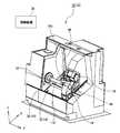
以下、本発明の実施形態について図面を参照して説明する。図1は、本発明の実施形態である工作機械10の構成を示す図である。以下の説明では、ワーク主軸32の回転軸方向をZ軸、刃物台18のZ軸と直交する移動方向をX軸、X軸およびZ軸に直交する方向をY軸と呼ぶ。また、Z軸においては、ワーク主軸32から心押台16に近づく方向をプラス方向、X軸においては、ワーク主軸32から刃物台18に向かう方向をプラス方向、Y軸においては、ワーク主軸32から上に向かう方向をプラス方向とする。また、以下の説明において、エンドエフェクタ46が「アクセスする」とは、機内ロボット20のエンドエフェクタ46が、当該エンドエフェクタ46の目的を達成できる位置まで対象物に接近することを意味する。したがって、機内ロボット20のエンドエフェクタ46が、接触して温度を検知する温度センサである場合、「アクセスする」とは、当該エンドエフェクタ46が対象物に接触する位置まで接近することである。また、エンドエフェクタ46が、非接触で温度を検知する温度センサである場合、「アクセスする」とは、当該エンドエフェクタ46が対象物の温度が検知できる位置まで対象物に接近することである。 Hereinafter, embodiments of the present invention will be described with reference to the drawings. FIG. 1 is a diagram showing a configuration of a
この工作機械10は、自転するワーク110に刃物台18で保持した工具100を当てることで、ワーク110を加工する旋盤である。本実施形態の工作機械10は、NC制御されるとともに、複数の工具100を保持するターニングセンタと呼ばれる旋盤である。工作機械10の本体部12の周囲は、カバー(図示せず)で覆われている。このカバーで区画される空間が、ワーク110の加工が行われる加工室となる。カバーには、少なくとも一つの開口部と、当該開口部を開閉するドア(いずれも図示せず)と、が設けられている。オペレータは、この開口部を介して、工作機械10の本体部12やワーク110等にアクセスする。加工中、開口部に設けられたドアは、閉鎖される。これは、安全性や環境性等を担保するためである。 The
本体部12は、ワーク110の一端を自転可能に保持するワーク主軸装置14と、工具100を保持する刃物台18と、ワーク110の他端を支える心押台16と、を備えている。ワーク主軸装置14は、駆動用モータ等を内蔵した主軸台30と、当該主軸台30に取り付けられたワーク主軸32と、を備えている。ワーク主軸32は、ワーク110を着脱自在に保持するチャック33やコレットを備えており、保持するワーク110を適宜、交換できる。また、ワーク主軸32およびチャック33は、水平方向(図1におけるZ軸方向)に延びるワーク回転軸Rwを中心として自転する。 The
心押台16は、Z軸方向に、ワーク主軸装置14と対向して配置されており、ワーク主軸装置14で保持されたワーク110の他端を支える。心押台16は、その中心軸が、ワーク回転軸Rwと一致するような位置に設置されている。心押台16には、先端が円錐形に尖ったセンタが取り付けられており、加工中は、当該センタの先端を、ワーク110の中心点に当接させる。心押台16は、ワーク110に対して接離できるように、Z軸方向に移動可能となっている。 The
刃物台18は、工具100、例えば、バイトと呼ばれる工具を保持する。この刃物台18は、Z軸方向、すなわち、ワーク110の軸方向に移動可能となっている。また、刃物台18は、X軸方向、すなわち、ワーク110の径方向に延びるガイドレールに載置されており、X軸方向にも進退できるようになっている。なお、図1から明らかな通り、X軸方向は、水平方向に対して傾いている。刃物台18の先端には、複数の工具100を保持可能なタレット36が設けられている。このタレット36は、Z軸方向に延びる軸を中心として回転可能となっている。そして、タレット36が回転することで、ワーク110の加工に用いられる工具100が適宜、変更できる。刃物台18を、Z軸方向に移動することで、このタレット36に保持された工具100は、Z軸方向に移動する。また、刃物台18をX軸方向に移動させることで、タレット36に保持された工具100は、X軸方向に移動する。そして、刃物台18をX軸方向に移動させることで、工具100によるワーク110の切り込み量等が変更できる。つまり、刃物台18に取り付けられた工具100は、XZ平面内で移動可能となっている。 The
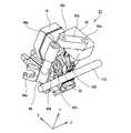
この刃物台18には、機内ロボット20(図1では図示せず)が取り付けられている。機内ロボット20は、図2に示す通り、刃物台18の上面に取り付けられている。この機内ロボット20は、加工の補助や、各種センシング、補助的作業等に用いられる。この機内ロボット20の構成や機能については、後に詳説する。 An in-machine robot 20 (not shown in FIG. 1) is attached to the
制御装置34は、オペレータからの指示に応じて、工作機械10の各部の駆動を制御する。この制御装置34は、例えば、各種演算を行うCPUと、各種制御プログラムや制御パラメータを記憶するメモリと、で構成される。また、制御装置34は、通信機能を有しており、他の装置との間で各種データ、例えば、NCプログラムデータ等を授受できる。この制御装置34は、例えば、工具100やワーク110の位置を随時演算する数値制御装置を含んでもよい。また、制御装置34は、単一の装置でもよいし、複数の演算装置を組み合わせて構成されてもよい。 The
次に、刃物台18に取り付けられた機内ロボット20について図2、図3を参照して説明する。図2、図3は、機内ロボット20周辺の斜視図である。図2に示す通り、機内ロボット20は、複数のアーム42a〜42dと、複数の関節44a〜44dを有したアーム型ロボットであり、多関節ロボットである。この機内ロボット20は、連結部40を介して刃物台18の上面に取り付けられている。 Next, the in-
機内ロボット20は、第一〜第三アーム42a〜42c(以下、第一〜第三を区別しない場合は、添字のアルファベットを省略して「アーム」とのみ言う。他部材においても同じ)と、これらの端部に設けられた第一〜第三関節44a〜44cと、エンドエフェクタ46a,46bと、を備えている。第一アーム42aの基端は、第一関節44aを介して連結部40に、第二アーム42bの基端は、第二関節44bを介して第一アーム42aの先端に、第三アーム42cの基端は、第三関節44cを介して第二アーム42bの先端に、それぞれ接続されている。第一〜第三関節44a〜44cは、いずれも、Y軸に平行な揺動軸を有しており、各アーム42は、当該揺動軸を中心として揺動する。第一〜第三関節44a〜44cには、モータ等のアクチュエータが取り付けられており、このアクチュエータの駆動は、制御装置34により制御される。制御装置34は、連結部40および各関節44a〜44cに設けられたアクチュエータの駆動量から、後述するエンドエフェクタ46a,46bの位置を算出する。 The in-
第三アーム42cの先端には、対象物に働きかけるエンドエフェクタ46a,46bが設けられている。本実施形態では、第三アーム42cの先端に取り付けられた軸部48の両端に、第一エンドエフェクタ46aおよび第二エンドエフェクタ46bを設けている。第一、第二エンドエフェクタ46a,46bは、何らかの効果を発揮するものであれば、特に限定されない。本実施形態では、第一エンドエフェクタ46aを、対象物を保持する保持装置とし、第二エンドエフェクタ46bを、対象物や対象物の周辺環境に関する情報をセンシングするセンサとしている。保持装置における保持の形式は、一対の部材で対象物を把持するハンド形式でもよいし、対象物を吸引保持する形式でもよいし、磁力等を利用して保持する形式等でもよい。図2、図3には、第一エンドエフェクタ46aをハンド形式とした場合の例を示している。 At the tip of the
また、センサとしては、例えば、対象物への接触の有無を検知する接触センサや、対象物までの距離を検知する距離センサ、対象物の振動を検知する振動センサ、対象物から付加される圧力を検知する圧力センサ、対象物の温度を検知するセンサ等とすることができる。これらセンサでの検知結果は、関節44a〜44cの駆動量から算出される第二エンドエフェクタ46bの位置情報と関連付けて記憶され、解析される。例えば、第二エンドエフェクタ46bが、接触センサの場合、制御装置34は、対象物への接触を検知したタイミングと、そのときの位置情報と、に基づいて、対象物の位置や形状、動きを解析する。 Further, as the sensor, for example, a contact sensor that detects the presence or absence of contact with the object, a distance sensor that detects the distance to the object, a vibration sensor that detects the vibration of the object, a pressure applied from the object Can be a pressure sensor for detecting the temperature, a sensor for detecting the temperature of the object, or the like. The detection results of these sensors are stored and analyzed in association with the position information of the
ただし、ここで例示したエンドエフェクタ46は、一例であり、対象物に働きかけるものであれば、他の形態でもよい。例えば、エンドエフェクタ46は、対象物を押圧する押圧機構としてもよい。具体的には、例えば、エンドエフェクタ46は、ワーク110に押し当てられて、当該ワーク110の振動を抑制するローラ等でもよい。 However, the end effector 46 illustrated here is an example, and another form may be used as long as it acts on the object. For example, the end effector 46 may be a pressing mechanism that presses an object. Specifically, for example, the end effector 46 may be a roller or the like that is pressed against the
また、別の形態として、エンドエフェクタ46は、加工を補助するための流体を出力する装置でもよい。具体的には、エンドエフェクタ46は、切粉を吹き飛ばすためのエアや、工具100またはワーク110を冷却するための冷却用流体(切削油や切削水等)を放出する装置でもよい。また、エンドエフェクタ46は、ワーク造形のためエネルギまたは材料を放出する装置でもよい。したがって、エンドエフェクタ46は、例えば、レーザやアークを放出する装置でもよいし、積層造形のために材料を放出する装置でもよい。さらに別の形態として、エンドエフェクタ46は、対象物を撮影するカメラでもよい。この場合、カメラで得た映像を操作パネル等に表示してもよい。 As another form, the end effector 46 may be a device that outputs a fluid for assisting processing. Specifically, the end effector 46 may be a device that discharges air for blowing off chips and a cooling fluid (cutting oil, cutting water, etc.) for cooling the
いずれにしても、本実施形態では、工具100の移動平面と、エンドエフェクタ46の移動平面とを一致させている。その結果、エンドエフェクタ46は、工具100の近傍に、確実にアクセスできる。そして、工具100の近傍には、加工中のワーク110が存在しているため、本実施形態のエンドエフェクタ46は、工具100だけでなく、加工中のワーク110にも、アクセスしやすいと言える。 In any case, in the present embodiment, the moving plane of the
ここで、本実施形態では、機内ロボット20を、Y軸に平行な軸回りに回転可能な複数の関節を有した構成であって、いわゆる「スカラ型ロボット」(水平多関節ロボット)に類似した構成としている。かかる構成とした場合、エンドエフェクタ46は、工具100の移動平面内で移動するため、機内ロボット20の可動範囲が比較的小さい、ひいては、各アーム42の長さが比較的短くても、エンドエフェクタ46を工具100やワーク110の近傍に容易に位置させることができる。結果として、機内ロボット20を小型に抑えつつも、エンドエフェクタ46を工具100やワーク110に確実にアクセスさせることができる。 Here, in the present embodiment, the in-
なお、ロボットの構成としては、Y軸に平行な軸回りの関節を有した構成に限らず、他の軸、例えばX軸やZ軸回りの関節を有した構成(いわゆる垂直多関節ロボットに類似した構成)等も考えられる。かかる構成の場合、エンドエフェクタのアクセスできる範囲や姿勢の自由度を大きくできる。したがって、エンドエフェクタで、様々な箇所、例えば、加工室のカバー等へのアクセスが必要な場合には、垂直多関節ロボットに類似した構成も有用である。しかし、本実施形態の機内ロボット20は、主に、工具100周辺の部材、例えば、工具100やワーク110、ワーク主軸装置14、心押台16へのアクセスのみを想定している。かかる場合においては、垂直多関節ロボットに類似した構成を採用した場合、ロボットの、刃物台18の上側への突出量が大きくなり、工作機械の大型化を招く。一方、本実施形態の機内ロボット20のように、エンドエフェクタ46の移動平面を、工具の移動平面と平行な平面に限定した場合、刃物台18の上側への突出量を低減できる。結果として、工作機械10を小型に抑えつつも、十分な作業性を確保できる。 The configuration of the robot is not limited to the configuration having joints about an axis parallel to the Y-axis, but a configuration having joints about other axes, for example, the X-axis or the Z-axis (similar to a so-called vertical articulated robot. The configuration) and the like are also possible. With such a configuration, it is possible to increase the accessible range of the end effector and the degree of freedom of posture. Therefore, when the end effector needs to access various places, for example, the cover of the processing chamber, a configuration similar to the vertical articulated robot is also useful. However, the in-
また、これまでの説明で明らかな通り、本実施形態では、機内ロボット20を、刃物台18に取り付け、刃物台18とともに移動可能としている。かかる構成とすることで、刃物台18の移動、つまり、切削点の移動に伴って機内ロボット20も移動できるため、エンドエフェクタ46は、常に、切削点近傍にアクセスできる。なお、機内ロボット20が、刃物台18とともに移動しない構成とした場合、機内ロボット20は、切削点にアクセスするためには、刃物台18の可動範囲以上の可動範囲が必要となる。特に、長尺のワーク110を扱うために、刃物台18のZ軸方向の可動範囲が大きい場合、機内ロボット20は、当該刃物台18の可動範囲をカバーするべく、大型にせざるを得ない。一方、本実施形態のように、機内ロボット20を刃物台18とともに移動する構成とした場合、機内ロボット20を小型に抑えつつも、エンドエフェクタ46を常に切削点近傍にアクセスさせることができる。 Further, as is clear from the above description, in the present embodiment, the in-
また、本実施形態では、機内ロボット20を刃物台18の前面(ワーク110との対向面)や、側面ではなく、上面に取り付けている。かかる構成とすることで、刃物台18と機内ロボット20との干渉を生じにくくすることができる。 Further, in the present embodiment, the in-
次に、上述したような機内ロボット20の動きについて説明する。ワーク110を加工する際には、ワーク主軸装置14でワーク110を自転させつつ、当該ワーク110に刃物台18で保持された工具100を当てる。刃物台18に取り付けられた機内ロボット20は、必要に応じて、加工の補助や、センシング、補助的作業等を行う。このとき、機内ロボット20は、必要に応じて、各関節44を動かして、エンドエフェクタ46を変化させる。 Next, the movement of the in-
こうした機内ロボット20は、種々の用途に用いることができる。例えば、機内ロボット20は、ワーク110を加工している間、当該加工を補助してもよい。具体的には、例えば、機内ロボット20は、加工中、ワーク110および工具100の少なくとも一方を、支持する。なお、加工中、ワーク110は、Z軸回りに回転するため、加工中にワーク110をエンドエフェクタ46で支持する場合は、エンドエフェクタ46を、ワーク110の回転を阻害しないローラや、ローラを有したハンド等にすることが望ましい。いずれにしても、エンドエフェクタ46でワーク110または工具100を支持することで、低剛性のワーク110/工具100の振動やたわみ等を抑制できる。また、ワーク110の振動を抑えることで、複雑なワーク形状にも対応できる。また、別の形態として、機内ロボット20は、加工中、ワーク110や工具100に振動を付与するようにしてもよい。これにより、振動を付与しながら切削を行う特殊な加工が可能となる。さらに、別の形態として、機内ロボット20は、加工中、冷却用の流体(切削油、切削水)や、切粉除去のためのエアを放出してもよい。その位置や姿勢を自由に変更できる機内ロボット20で冷却用流体またはエアを放出すれば、ワーク110および工具100の切削性や温度を、より自由にコントロールできる。 The in-
また、機内ロボット20は、例えば、ワーク110を加工している間、または、加工の前後において、各種センシングを行ってもよい。図2、図3は、第二エンドエフェクタ46bであるセンサで、センシングを行っている様子を示している。具体的には、例えば、機内ロボット20で、切削状態(加工面精度や切粉の状態)を監視してもよい。また、別の形態として、機内ロボット20は、加工中に、ワーク110や、工具100の状態、例えば、温度や振動、ひずみ等をセンシングし、制御装置34に出力してもよい。この場合、制御装置34は、機内ロボット20で検知された情報に基づいて、必要であれば、各種加工条件(送り速度や回転速度等)を変更することが望ましい。また、機内ロボット20は、加工の開始前、または、終了後に、ワーク110の形状を計測する構成としてもよい。加工開始前にワーク110の形状を計測することで、ワーク110の取付間違いを確実に防止できる。また、加工開始後にワーク110の形状を計測することで、加工結果の良否を判定することができる。また、別の形態として、機内ロボット20は、例えば、加工の開始前、または、終了後に、工具100の状態(摩耗量等)を計測してもよい。さらに、また、別の形態として、機内ロボット20は、加工を行っていない期間中に、工具の点検(摩耗の有無確認等)や、工作機械10の可動部(ワーク主軸装置14や心押台16等)の点検を行ってもよい。 Further, the in-
さらに、機内ロボット20は、従来、機外ロボットが行っていた作業を、加工中、または、加工の完了後に行うようにしてもよい。例えば、機内ロボット20は、ワーク110に対して付加的な加工(例えば、バリ取り加工や、金型磨き加工のような除去加工、表面改質、付加加工等)を行ってもよい。また、機内ロボット20は、ワーク110や工具100の搬送や、交換、段取等を行ってもよい。また、機内ロボット20は、各種部品の検査や組み立て等を行ってもよい。 Further, the in-
なお、これまで説明した機内ロボット20の構成は、一例である。機内ロボット20は、Y軸回りに回転可能な複数の関節を有し、エンドエフェクタ46が、工具100の移動平面と平行な面内で移動可能であれば、その他の構成は適宜、変更されてもよい。したがって、機内ロボット20の関節44やアーム42の数、揺動の方向等は、適宜、変更されてもよい。 Note that the configuration of the in-
また、本実施形態では、エンドエフェクタ46の移動平面と、工具100との移動平面とを一致させているが、両者は、平行であれば、一致していなくてもよい。したがって、エンドエフェクタ46が、工具100の移動平面より僅かに上側、または、下側に位置する平面内で移動するような構成としてもよい。また、本実施形態では、機内ロボット20の関節44として、Y軸と平行な軸回りに回転可能な関節のみを例示したが、例えば、一般的なスカラ型ロボットと同様に、第三アームの先端や第一アームの根元等に、Y軸と平行な軸方向に直進退できる関節を設けてもよい。この場合、機内ロボット20は、平面3自由度の位置決めとアームの軸方向に沿った上下運動の合計4自由度を持つことになる。 Further, in the present embodiment, the moving plane of the end effector 46 and the moving plane of the
また、本実施形態では、機内ロボット20を工具100を保持する刃物台18に取り付けたが、長尺ワークを扱わない小型旋盤の場合、機内ロボット20は、他の箇所に取り付けられてもよい。例えば、機内ロボット20は、工作機械の非移動体や、心押台16等に取り付けられてもよい。この場合でも、機内ロボット20を、そのエンドエフェクタ46が、工具100の移動平面と平行な面内で移動可能な構成とすることで、エンドエフェクタ46を、切削点近傍に、容易にアクセスさせることができる。 Further, in the present embodiment, the in-
また、本実施形態の工作機械10は、旋盤、より詳しくは、ターニングセンタであるが、本実施形態の機内ロボット20は、他の種類の工作機械に用いられてもよい。例えば、機内ロボット20は、ワークを回転させて切削する旋盤機能と、回転工具を回転させて切削する転削機能と、を有した複合機に搭載されてもよい。また、別の形態として、機内ロボット20は、ワークを回転させて研削を行う円筒研削盤に搭載されてもよい。 The
また、本実施形態では、一つの機内ロボット20に二つのエンドエフェクタ46を設けているが、エンドエフェクタ46の個数は、適宜、変更されてもよい。したがって、例えば、機内ロボット20は、単一のエンドエフェクタ46を有してもよいし、3つ以上のエンドエフェクタを有してもよい。 Further, in the present embodiment, two end effectors 46 are provided in one in-
10 工作機械、12 本体部、14 ワーク主軸装置、16 心押台、18 刃物台、20 機内ロボット、30 主軸台、32 ワーク主軸、33 チャック、34 制御装置、36 タレット、40 連結部、42 アーム、44 関節、46a 第一エンドエフェクタ、46b 第二エンドエフェクタ、48 軸部、100 工具、110 ワーク。
10 machine tools, 12 main body part, 14 work spindle device, 16 tailstock, 18 tool rest, 20 in-machine robot, 30 headstock, 32 work spindle, 33 chuck, 34 control device, 36 turret, 40 connecting part, 42 arm , 44 joints, 46a first end effector, 46b second end effector, 48 shaft part, 100 tool, 110 work.
Claims (5)
Translated fromJapanese複数のアームと、複数の関節と、エンドエフェクタと、を有した多関節のロボットを備え、
前記複数の関節は、前記アームを、前記第一軸および第二軸に直交する第三軸に平行な軸回りに回転可能に連結し、
前記エンドエフェクタは、前記工具の移動平面と平行な平面内で移動し、
前記ロボットは、前記刃物台に取り付けられ、前記刃物台とともに第一軸方向および第二軸方向に移動する、
ことを特徴とする工作機械。A work spindle device for rotating the work, a first axial direction that is the radial direction of the work, and a tool post that can move the tool in the second axial direction that is the axial direction of the work, and A machine tool,
A multi-joint robot having a plurality of arms, a plurality of joints, and an end effector is provided,
The plurality of joints connect the arm rotatably about an axis parallel to a third axis orthogonal to the first axis and the second axis,
The end effector moves in a plane parallel to the plane of movement of the tool,
The robot is attached to the tool rest, and moves in the first axial direction and the second axial direction together with the tool rest,
A machine tool characterized by that.
複数のアームと、複数の関節と、エンドエフェクタと、を有した多関節のロボットを備え、 A multi-joint robot having a plurality of arms, a plurality of joints, and an end effector is provided,
前記複数の関節は、前記アームを、前記第一軸および第二軸に直交する第三軸に平行な軸回りに回転可能に連結し、 The plurality of joints connects the arm rotatably about an axis parallel to a third axis orthogonal to the first axis and the second axis,
前記エンドエフェクタは、前記工具の移動平面と平行な平面内で移動し、 The end effector moves in a plane parallel to the plane of movement of the tool,
さらに、ワーク主軸に対向して配置される心押台を備え、 Furthermore, it is equipped with a tailstock arranged to face the work spindle.
前記ロボットは、前記心押台に取り付けられる、 The robot is attached to the tailstock,
ことを特徴とする工作機械。 A machine tool characterized by that.
複数のアームと、複数の関節と、エンドエフェクタと、を有した多関節のロボットを備え、 A multi-joint robot having a plurality of arms, a plurality of joints, and an end effector is provided,
前記複数の関節は、前記アームを、前記第一軸および第二軸に直交する第三軸に平行な軸回りに回転可能に連結し、 The plurality of joints connects the arm rotatably about an axis parallel to a third axis orthogonal to the first axis and the second axis,
前記エンドエフェクタは、前記工具の移動平面と平行な平面内で移動し、 The end effector moves in a plane parallel to the plane of movement of the tool,
前記第一軸方向は、水平方向に対して傾いている、 The first axial direction is inclined with respect to the horizontal direction,
ことを特徴とする工作機械。 A machine tool characterized by that.
前記エンドエフェクタは、前記工具の移動平面と同じ平面内で移動する、ことを特徴とする工作機械。The machine tool according toany one of claims 1to 3 ,
The machine tool, wherein the end effector moves in the same plane as the movement plane of the tool.
前記ロボットのエンドエフェクタは、前記工具による前記ワークの加工の補助、前記加工中における前記工具または前記ワークに関するセンシング、および、付加的な加工の少なくとも一つを行う、ことを特徴とする工作機械。The machine tool according to any one of claims 1 to4 ,
A machine tool, wherein the end effector of the robot performs at least one of assisting the machining of the work by the tool, sensing the tool or the work during the machining, and performing additional machining.
Priority Applications (4)
| Application Number | Priority Date | Filing Date | Title |
|---|---|---|---|
| JP2016110230AJP6709111B2 (en) | 2016-06-01 | 2016-06-01 | Machine Tools |
| US15/603,872US10391559B2 (en) | 2016-06-01 | 2017-05-24 | Machine tool |
| DE102017111915.9ADE102017111915A1 (en) | 2016-06-01 | 2017-05-31 | machine tool |
| CN201710405315.8ACN107443145B (en) | 2016-06-01 | 2017-06-01 | Machine tool |
Applications Claiming Priority (1)
| Application Number | Priority Date | Filing Date | Title |
|---|---|---|---|
| JP2016110230AJP6709111B2 (en) | 2016-06-01 | 2016-06-01 | Machine Tools |
Publications (2)
| Publication Number | Publication Date |
|---|---|
| JP2017213658A JP2017213658A (en) | 2017-12-07 |
| JP6709111B2true JP6709111B2 (en) | 2020-06-10 |
Family
ID=60327669
Family Applications (1)
| Application Number | Title | Priority Date | Filing Date |
|---|---|---|---|
| JP2016110230AActiveJP6709111B2 (en) | 2016-06-01 | 2016-06-01 | Machine Tools |
Country Status (4)
| Country | Link |
|---|---|
| US (1) | US10391559B2 (en) |
| JP (1) | JP6709111B2 (en) |
| CN (1) | CN107443145B (en) |
| DE (1) | DE102017111915A1 (en) |
Families Citing this family (11)
| Publication number | Priority date | Publication date | Assignee | Title |
|---|---|---|---|---|
| JP6502976B2 (en)* | 2017-02-15 | 2019-04-17 | ファナック株式会社 | Numerical control device |
| JP6470336B2 (en)* | 2017-03-27 | 2019-02-13 | ファナック株式会社 | Machine tool system and moving method |
| JP7188880B2 (en)* | 2017-12-05 | 2022-12-13 | オークマ株式会社 | Machine Tools |
| US20190291270A1 (en)* | 2018-03-20 | 2019-09-26 | Fanuc Corporation | Controller, machine learning device, and system |
| CN108871234A (en)* | 2018-07-10 | 2018-11-23 | 苏州艾弗伦智能技术有限公司 | Non-contact 3-D automatic scanning test macro |
| JP7387257B2 (en) | 2018-09-21 | 2023-11-28 | オークマ株式会社 | robot unit |
| JP7100555B2 (en)* | 2018-10-05 | 2022-07-13 | オークマ株式会社 | Machine Tools |
| JP7211777B2 (en)* | 2018-11-27 | 2023-01-24 | オークマ株式会社 | Machine Tools |
| JP7315407B2 (en)* | 2019-08-06 | 2023-07-26 | オークマ株式会社 | Machine Tools |
| WO2022118474A1 (en)* | 2020-12-04 | 2022-06-09 | ヤマザキマザック株式会社 | Method for pressing tailstock of machining device, pressing device, computer program, and computer-readable storage medium |
| JP7502987B2 (en)* | 2020-12-25 | 2024-06-19 | 株式会社ツガミ | Machine Tools |
Family Cites Families (39)
| Publication number | Priority date | Publication date | Assignee | Title |
|---|---|---|---|---|
| US3963271A (en)* | 1974-10-15 | 1976-06-15 | Yamatake-Honeywell Company, Limited | Finger mechanisms of industrial robots |
| US4432063A (en)* | 1981-10-06 | 1984-02-14 | Cincinnati Milacron Inc. | Apparatus for automatically moving a robot arm along a nonprogrammed path |
| US4838135A (en)* | 1986-07-31 | 1989-06-13 | Hevoyan Varoujan H | Work transport for machine tools |
| US5168609A (en)* | 1987-12-24 | 1992-12-08 | Yamazaki Mazik Corp. | Workpiece support for a turret on a opposed spindle lathe |
| US4878705A (en)* | 1988-03-18 | 1989-11-07 | Texas Instruments Incorporated | Robot gripper passively locked |
| JPH045349U (en)* | 1990-04-27 | 1992-01-17 | ||
| JPH04101741A (en)* | 1990-08-17 | 1992-04-03 | Yamazaki Mazak Corp | Tool-exchange method and automatic tool-exchange device in neumerical control (nc) lathe |
| JPH05301141A (en) | 1992-04-28 | 1993-11-16 | Enshu Ltd | Machine tool with carrying device |
| JPH05301142A (en) | 1992-04-28 | 1993-11-16 | Enshu Ltd | Machine tool with carrying device |
| US5758554A (en)* | 1996-12-05 | 1998-06-02 | Miyano; Toshiharu Tom | Machine tool and method for machining a long-shafted workpiece |
| JP2002337012A (en)* | 2001-05-14 | 2002-11-26 | Nsk Ltd | Ring-shaped workpiece processing equipment |
| JP2004142015A (en)* | 2002-10-24 | 2004-05-20 | Fanuc Ltd | Robot with sensor |
| JP4098761B2 (en)* | 2004-08-17 | 2008-06-11 | ファナック株式会社 | Finishing method |
| DE102006003985A1 (en)* | 2006-01-20 | 2007-07-26 | Index-Werke Gmbh & Co. Kg Hahn & Tessky | Machine tool, for a workpiece on a spindle, has a passage opening in a wall for the manipulator to place and remove the workpiece at the spindle |
| CN101454101A (en)* | 2006-04-07 | 2009-06-10 | 史蒂文·S·米亚诺 | Small high-precision multi-spindle computer controlled machine tool |
| JP4825646B2 (en)* | 2006-11-20 | 2011-11-30 | オークマ株式会社 | Chip cleaning device in NC processing machine |
| JP4833887B2 (en)* | 2007-02-26 | 2011-12-07 | オークマ株式会社 | Turret tool post and machine tool |
| JP4955522B2 (en)* | 2007-11-29 | 2012-06-20 | ヤマザキマザック株式会社 | Automatic chuck claw change system for multi-tasking lathe |
| JP4603604B2 (en)* | 2008-08-01 | 2010-12-22 | ファナック株式会社 | Robot system that attaches and detaches workpieces to machine tools by robot |
| JP2010064158A (en) | 2008-09-08 | 2010-03-25 | Yamazaki Mazak Corp | Machining equipment |
| JP5270299B2 (en)* | 2008-10-28 | 2013-08-21 | オークマ株式会社 | Combined lathe |
| JP5465922B2 (en)* | 2009-05-15 | 2014-04-09 | Dmg森精機株式会社 | Processing method and processing system |
| DE102013012633A1 (en)* | 2013-07-29 | 2015-01-29 | Alfing Kessler Sondermaschinen Gmbh | Machine tool with a workpiece changing device |
| CN104608113B (en)* | 2013-11-01 | 2018-07-17 | 精工爱普生株式会社 | Robot, robot system and robot controller |
| US9308644B2 (en)* | 2013-12-05 | 2016-04-12 | Hiwin Technologies Corp. | Robotic arm for processing machine |
| CN204094465U (en)* | 2014-07-22 | 2015-01-14 | 深圳市大富科技股份有限公司 | Complex milling machine tool |
| US9656390B2 (en)* | 2014-11-10 | 2017-05-23 | Faro Technologies, Inc. | Human-centric robot with noncontact measurement device |
| JP5944975B2 (en) | 2014-12-02 | 2016-07-05 | 株式会社ピーチ・ボーイ | Story display program and story display system |
| CN204308427U (en)* | 2014-12-12 | 2015-05-06 | 付建生 | A kind of automatic welding machine |
| CN204450042U (en)* | 2014-12-16 | 2015-07-08 | 广州市敏嘉制造技术有限公司 | Machining of Shaft-type Parts lathe |
| US10086487B2 (en)* | 2014-12-25 | 2018-10-02 | Fanuc Corporation | Internal cleaning device of machine tool |
| JP2016215343A (en)* | 2015-05-22 | 2016-12-22 | ファナック株式会社 | Machine tool having cleaning means |
| JP6630073B2 (en)* | 2015-07-09 | 2020-01-15 | 株式会社Subaru | Machining device and machining method |
| JP6666112B2 (en)* | 2015-10-27 | 2020-03-13 | ファナック株式会社 | Tool cleaning equipment for machine tools |
| CN105479177A (en)* | 2016-01-14 | 2016-04-13 | 巨鑫机床有限公司 | Automatic shaft part production line machine tool |
| JP6434446B2 (en)* | 2016-04-28 | 2018-12-05 | ファナック株式会社 | Processing system |
| JP6787688B2 (en)* | 2016-05-16 | 2020-11-18 | オークマ株式会社 | Machine Tools |
| JP6756539B2 (en)* | 2016-08-04 | 2020-09-16 | オークマ株式会社 | Machine Tools |
| JP6490037B2 (en)* | 2016-10-04 | 2019-03-27 | ファナック株式会社 | Robot system comprising a robot supported by a movable carriage |
- 2016
- 2016-06-01JPJP2016110230Apatent/JP6709111B2/enactiveActive
- 2017
- 2017-05-24USUS15/603,872patent/US10391559B2/enactiveActive
- 2017-05-31DEDE102017111915.9Apatent/DE102017111915A1/enactivePending
- 2017-06-01CNCN201710405315.8Apatent/CN107443145B/enactiveActive
Also Published As
| Publication number | Publication date |
|---|---|
| JP2017213658A (en) | 2017-12-07 |
| US10391559B2 (en) | 2019-08-27 |
| US20170348772A1 (en) | 2017-12-07 |
| CN107443145A (en) | 2017-12-08 |
| CN107443145B (en) | 2021-08-24 |
| DE102017111915A1 (en) | 2017-12-07 |
Similar Documents
| Publication | Publication Date | Title |
|---|---|---|
| JP6735149B2 (en) | Machine Tools | |
| JP6735148B2 (en) | Machine Tools | |
| JP6709111B2 (en) | Machine Tools | |
| JP6787688B2 (en) | Machine Tools | |
| CN109877626B (en) | Machine tool | |
| JP6756539B2 (en) | Machine Tools | |
| KR102662204B1 (en) | Machine tool | |
| JP7315407B2 (en) | Machine Tools | |
| JP2018030180A (en) | Machine tool |
Legal Events
| Date | Code | Title | Description |
|---|---|---|---|
| A621 | Written request for application examination | Free format text:JAPANESE INTERMEDIATE CODE: A621 Effective date:20190228 | |
| A977 | Report on retrieval | Free format text:JAPANESE INTERMEDIATE CODE: A971007 Effective date:20200122 | |
| A131 | Notification of reasons for refusal | Free format text:JAPANESE INTERMEDIATE CODE: A131 Effective date:20200218 | |
| A521 | Request for written amendment filed | Free format text:JAPANESE INTERMEDIATE CODE: A523 Effective date:20200409 | |
| TRDD | Decision of grant or rejection written | ||
| A01 | Written decision to grant a patent or to grant a registration (utility model) | Free format text:JAPANESE INTERMEDIATE CODE: A01 Effective date:20200519 | |
| A61 | First payment of annual fees (during grant procedure) | Free format text:JAPANESE INTERMEDIATE CODE: A61 Effective date:20200522 | |
| R150 | Certificate of patent or registration of utility model | Ref document number:6709111 Country of ref document:JP Free format text:JAPANESE INTERMEDIATE CODE: R150 |