JP6707964B2 - Positioning device and rotation mechanism - Google Patents
Positioning device and rotation mechanismDownload PDFInfo
- Publication number
- JP6707964B2 JP6707964B2JP2016079625AJP2016079625AJP6707964B2JP 6707964 B2JP6707964 B2JP 6707964B2JP 2016079625 AJP2016079625 AJP 2016079625AJP 2016079625 AJP2016079625 AJP 2016079625AJP 6707964 B2JP6707964 B2JP 6707964B2
- Authority
- JP
- Japan
- Prior art keywords
- gap
- space
- plate
- air supply
- shaped member
- Prior art date
- Legal status (The legal status is an assumption and is not a legal conclusion. Google has not performed a legal analysis and makes no representation as to the accuracy of the status listed.)
- Active
Links
Images


Landscapes
- Exposure And Positioning Against Photoresist Photosensitive Materials (AREA)
- Bearings For Parts Moving Linearly (AREA)
- Sealing Of Bearings (AREA)
- Container, Conveyance, Adherence, Positioning, Of Wafer (AREA)
- Exposure Of Semiconductors, Excluding Electron Or Ion Beam Exposure (AREA)
Description
Translated fromJapanese本発明は、位置決め装置及び回転機構に関する。 The present invention relates to a positioning device and a rotation mechanism.
搬送装置、工作機械又は半導体製造装置には、真空雰囲気や特殊ガス雰囲気のプロセス室内でステージを回転させる回転機構や、ステージをスライド移動させる位置決め装置が用いられる。下記特許文献1には、真空室を囲み、開口が設けられた壁と、この開口をシールする摺動シールプレートとを有するリソグラフィ装置(位置決め装置)が記載されている。特許文献1では、壁と摺動シールプレートとの隙間に高圧の気体を供給して、隙間部分に高圧領域を発生させることで、壁と摺動シールプレートとの間が非接触でシールされる。 A rotating mechanism that rotates a stage in a process chamber in a vacuum atmosphere or a special gas atmosphere, and a positioning device that slides the stage are used in a carrier device, a machine tool, or a semiconductor manufacturing device.
しかし、特許文献1では、供給された気体が一部真空室に漏れ出す可能性があり、真空室内の気流の状態が乱される場合がある。また、真空室への気体の流入を抑制するために壁に複数の排気通路を設ける場合、構成が煩雑になる可能性がある。 However, in
本発明は、簡便な構成で、ワークの位置決めや検査を行う空間への気体の流入を抑制することが可能な位置決め装置及び回転機構を提供することを目的とする。 It is an object of the present invention to provide a positioning device and a rotation mechanism that have a simple structure and can suppress the inflow of gas into a space for positioning and inspecting a work.
本発明の一態様に係る位置決め装置は、筐体に囲まれた第1空間と、前記第1空間と異なる第2空間とを区切る板状部材と、前記板状部材に設けられた孔部を覆うとともに、前記板状部材の一方の面と隙間を有して対向する可動部と、前記板状部材の前記孔部に挿通され、前記可動部と連結される連結軸と、前記板状部材の前記孔部よりも外側において前記隙間に開口し、前記隙間へ気体を供給することにより、前記第1空間の気体を、前記隙間を通って前記第2空間側に流入させる給気部と、を有する。 A positioning device according to an aspect of the present invention includes a plate-shaped member that divides a first space surrounded by a housing and a second space different from the first space, and a hole provided in the plate-shaped member. A movable part that covers and faces one surface of the plate-shaped member with a gap, a connecting shaft that is inserted into the hole of the plate-shaped member and is connected to the movable part, and the plate-shaped member. An air supply unit that opens into the gap outside the hole portion and supplies gas to the gap to cause the gas in the first space to flow into the second space through the gap. Have.
この構成によれば、板状部材と可動部との隙間に、給気部から気体が供給されることにより、第1空間がシールされる。この給気部からの気体の供給により、第1空間の気体が隙間を通って第2空間側に流入する負圧が発生する。また、隙間の気体を排出するための配管や通路等を設ける必要がない。このため、簡便な構成で、ワークの位置決めや検査を行うための第1空間に気体が流入することを抑制できる。 According to this structure, the first space is sealed by supplying the gas from the air supply unit to the gap between the plate-shaped member and the movable unit. Due to the supply of the gas from the air supply unit, a negative pressure is generated in which the gas in the first space flows into the second space through the gap. Further, it is not necessary to provide a pipe or passage for discharging the gas in the gap. Therefore, with a simple configuration, it is possible to suppress the gas from flowing into the first space for positioning and inspecting the work.
本発明の一態様に係る位置決め装置において、前記給気部は、前記孔部の周りにスリット状に設けられている。この構成によれば、第1空間の気体が隙間を通って第2空間側に流入する負圧が、孔部の周方向に沿って全周に発生するため、確実に第1空間への気体の流入を抑制することができる。 In the positioning device according to one aspect of the present invention, the air supply unit is provided in a slit shape around the hole. According to this configuration, the negative pressure in which the gas in the first space flows into the second space through the gap is generated in the entire circumference along the circumferential direction of the hole, so that the gas to the first space is surely discharged. Can be suppressed.
本発明の一態様に係る位置決め装置において、前記隙間は、前記給気部よりも前記第1空間側の第1隙間と、前記給気部よりも前記第2空間側の第2隙間とを含み、前記第2隙間の間隔は、前記第1隙間の間隔よりも大きい。これによれば、いわゆるエゼクタ効果により、第1隙間において第1空間側から、第2空間側に向かう気体の流れが発生するため、第1空間へ気体が流入することを抑制できる。 In the positioning device according to one aspect of the present invention, the gap includes a first gap closer to the first space than the air supply part, and a second gap closer to the second space than the air supply part. The interval of the second gap is larger than the interval of the first gap. According to this, the so-called ejector effect causes a gas flow from the first space side toward the second space side in the first gap, so that the gas can be suppressed from flowing into the first space.
本発明の一態様に係る位置決め装置において、前記板状部材は、前記可動部側に突出する突出部が設けられている。これによれば、板状部材と可動部との隙間の調整が容易である。また、板状部材の強度が向上するため、隙間の間隔の変動を抑制できる。 In the positioning device according to an aspect of the present invention, the plate-shaped member is provided with a protrusion that protrudes toward the movable portion. According to this, it is easy to adjust the gap between the plate-shaped member and the movable portion. In addition, since the strength of the plate-shaped member is improved, it is possible to suppress variation in the gap.
本発明の一態様に係る位置決め装置において、前記突出部は、前記板状部材の前記孔部の周囲に環状に設けられる。これによれば、第1空間の気体が隙間を通って第2空間側に流入する負圧が、孔部の周方向に沿って全周に発生するため、確実に第1空間への気体の流入を抑制することができる。 In the positioning device according to one aspect of the present invention, the protrusion is provided in an annular shape around the hole of the plate member. According to this, since the negative pressure in which the gas in the first space flows into the second space through the gap is generated in the entire circumference along the circumferential direction of the hole, the gas in the first space is surely discharged. Inflow can be suppressed.
本発明の一態様に係る位置決め装置において、前記突出部の径方向外側の面と第3隙間を有して対向するシール部材が設けられ、前記給気部は、前記第3隙間を含む。これによれば、気体は第3隙間を通って第1隙間及び第2隙間に供給される。そして、シール部材と板状部材との間に隙間が形成され、この隙間を通って第1空間の気体が第2空間側に流入する。また、シール部材を設けることにより、可動部とシール部材との隙間の大きさの調整が容易であり、気体を供給するための第3隙間の調整も容易である。 In the positioning device according to an aspect of the present invention, a seal member that faces the radially outer surface of the protrusion with a third gap is provided, and the air supply unit includes the third gap. According to this, the gas is supplied to the first gap and the second gap through the third gap. Then, a gap is formed between the seal member and the plate-like member, and the gas in the first space flows into the second space side through the gap. Further, by providing the seal member, the size of the gap between the movable portion and the seal member can be easily adjusted, and the third gap for supplying the gas can be easily adjusted.
本発明の一態様に係る位置決め装置において、前記第3隙間の間隔は、前記第1隙間の間隔よりも小さく、かつ、前記第2隙間の間隔よりも小さい。これによれば、第3隙間を通る気体の流速が大きくなるので、確実に第1空間の気体が第1隙間及び第2隙間を通って第2空間側に流入する負圧を発生させることができる。 In the positioning device according to an aspect of the present invention, the third gap is smaller than the first gap and smaller than the second gap. According to this, the flow velocity of the gas passing through the third gap is increased, so that it is possible to reliably generate a negative pressure in which the gas in the first space flows into the second space through the first gap and the second gap. it can.
本発明の一態様に係る位置決め装置において、前記シール部材は、前記板状部材の前記一方の面と第4隙間を有して対向し、前記給気部は、前記第4隙間を含む。これによれば、シール部材と板状部材との第4隙間により給気部が構成されるため、シール部材と突出部との間の第3隙間を第4隙間よりも大きくすることができ、第3隙間及び第4隙間の寸法精度の管理が容易である。 In the positioning device according to an aspect of the present invention, the seal member faces the one surface of the plate-shaped member with a fourth gap, and the air supply unit includes the fourth gap. According to this, since the air supply unit is configured by the fourth gap between the seal member and the plate-shaped member, the third gap between the seal member and the protrusion can be made larger than the fourth gap, It is easy to control the dimensional accuracy of the third gap and the fourth gap.
本発明の一態様に係る位置決め装置において、前記第4隙間の間隔は、前記第1隙間、前記第2隙間、及び前記第3隙間の間隔よりも小さい。これによれば、第4隙間を通る気体の流速が大きくなるので、確実に第1空間の気体が第1隙間及び第2隙間を通って第2空間側に流入する負圧を発生させることができる。 In the positioning device according to one aspect of the present invention, the spacing of the fourth gap is smaller than the spacing of the first gap, the second gap, and the third gap. According to this, the flow velocity of the gas passing through the fourth gap is increased, so that it is possible to reliably generate a negative pressure in which the gas in the first space flows into the second space through the first gap and the second gap. it can.
本発明の一態様に係る位置決め装置において、前記シール部材と前記可動部との間に前記第1隙間が設けられ、前記突出部と前記可動部との間に前記第2隙間が設けられる。すなわち、シール部材が第1空間側に配置され、突出部がシール部材よりも第2空間側に配置される構成であっても、簡便な構成で、第1空間へ気体が流入することを抑制できる。 In the positioning device according to one aspect of the present invention, the first gap is provided between the seal member and the movable portion, and the second gap is provided between the protruding portion and the movable portion. That is, even if the seal member is arranged on the first space side and the protrusion is arranged on the second space side with respect to the seal member, it is possible to suppress the gas from flowing into the first space with a simple structure. it can.
本発明の一態様に係る位置決め装置において、前記突出部と前記可動部との間に前記第1隙間が設けられ、前記シール部材と前記可動部との間に前記第2隙間が設けられる。すなわち、突出部が第1空間側に配置され、シール部材が突出部よりも第2空間側に配置される構成であっても、簡便な構成で、第1空間へ気体が流入することを抑制できる。 In the positioning device according to an aspect of the present invention, the first gap is provided between the protruding portion and the movable portion, and the second gap is provided between the seal member and the movable portion. That is, even if the protruding portion is arranged on the first space side and the seal member is arranged on the second space side with respect to the protruding portion, the gas is prevented from flowing into the first space with a simple structure. it can.
本発明の一態様に係る位置決め装置において、前記可動部は、前記第1空間に配置され、前記板状部材の前記第1空間側の面と隙間を有して対向する。これによれば、隙間を形成する各部材が第1空間側に配置されるので、隙間の確認及び調整を容易に行うことができる。 In the positioning device according to one aspect of the present invention, the movable portion is arranged in the first space and faces a surface of the plate-shaped member on the first space side with a gap. According to this, since the members forming the gap are arranged on the first space side, the gap can be easily confirmed and adjusted.
本発明の一態様に係る位置決め装置は、前記第1空間に設けられ、ワークを移動させるためのステージを有し、前記可動部は、前記第2空間に配置され、前記連結軸を介して前記ステージと連結されており、前記板状部材の前記第2空間側の面と対向して配置される。これによれば、ステージの交換等の作業を行う場合であっても、シールを構成する各隙間の構成の変更がないため、メンテナンス等の作業を容易に行うことができる。 A positioning device according to an aspect of the present invention is provided in the first space, has a stage for moving a work, the movable part is arranged in the second space, and the movable shaft is provided with the stage via the connecting shaft. The stage is connected to the stage, and is arranged to face the surface of the plate-shaped member on the second space side. According to this, even when the work such as the replacement of the stage is performed, the configuration of each gap constituting the seal is not changed, and therefore the work such as the maintenance can be easily performed.
本発明の一態様に係る回転機構は、筐体に囲まれた第1空間と、前記第1空間と異なる第2空間とを区切る板状部材と、前記板状部材に設けられた孔部を覆うとともに、前記板状部材の前記第1空間側の面と隙間を有して対向する回転部材と、前記板状部材の前記孔部に挿通され、前記回転部材と連結される連結軸と、前記第2空間に設置されて前記連結軸を回転可能に支持する軸受と、前記板状部材の前記孔部の外側において前記隙間に開口し、前記隙間へ気体を供給することにより、前記第1空間の気体を、前記隙間を通って前記第2空間側に流入させる給気部と、を有する。 A rotation mechanism according to an aspect of the present invention includes a plate-shaped member that divides a first space surrounded by a housing and a second space different from the first space, and a hole provided in the plate-shaped member. A rotating member that covers and faces the surface of the plate-shaped member on the side of the first space with a gap, and a connecting shaft that is inserted into the hole of the plate-shaped member and connected to the rotating member. A bearing that is installed in the second space and rotatably supports the connecting shaft and an opening in the gap outside the hole of the plate-shaped member, and gas is supplied to the gap, whereby the first An air supply unit that allows the gas in the space to flow into the second space through the gap.
この構成によれば、板状部材と回転部材との隙間に、給気部から気体が供給されることにより、第1空間と、第2空間とがシールされる。この給気部の気体の供給により、第1空間の気体が隙間を通って第2空間側に流入する負圧が発生する。また、隙間の気体を排出するための配管や通路等を設ける必要がない。このため、簡便な構成で、ワークの位置決めや検査を行うための第1空間へ気体が流入することを抑制できる。 According to this configuration, the first space and the second space are sealed by supplying the gas from the air supply unit to the gap between the plate-shaped member and the rotating member. Due to the supply of gas from the air supply unit, a negative pressure is generated in which the gas in the first space flows into the second space through the gap. Further, it is not necessary to provide a pipe or passage for discharging the gas in the gap. Therefore, with a simple configuration, it is possible to suppress the gas from flowing into the first space for positioning and inspecting the work.
本発明によれば、簡便な構成で、ワークの位置決めや検査を行う空間への気体の流入を抑制することが可能な位置決め装置及び回転機構を提供することができる。 According to the present invention, it is possible to provide a positioning device and a rotation mechanism that have a simple structure and can suppress the inflow of gas into a space for positioning and inspecting a work.
発明を実施するための形態(実施形態)につき、図面を参照しつつ詳細に説明する。以下の実施形態に記載した内容により本発明が限定されるものではない。また、以下に記載した構成要素には、当業者が容易に想定できるもの、実質的に同一のものが含まれる。さらに、以下に記載した構成要素は適宜組み合わせることが可能である。なお、図面は、実施形態の説明のため、実際の寸法、形状と適宜変更して示している。 Modes (embodiments) for carrying out the invention will be described in detail with reference to the drawings. The present invention is not limited to the contents described in the embodiments below. Further, the constituent elements described below include those that can be easily conceived by those skilled in the art and those that are substantially the same. Furthermore, the components described below can be combined as appropriate. It should be noted that the drawings are shown by appropriately changing the actual dimensions and shapes for the description of the embodiments.
(第1の実施形態)
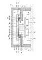
図1は、第1の実施形態に係る位置決め装置を模式的に示す断面図である。図2は、第1の実施形態に係る位置決め装置のシール構造を示す断面図である。図1は、連結軸32の中心軸を含み、かつ中心軸と平行な平面で位置決め装置10を切った断面を示している。位置決め装置10は、密閉空間内に配置されたワークを直線移動、又は回転移動させるための装置であり、工作機械、搬送装置、半導体製造装置、又は、減圧空間内でモールド加工を行うナノインプリント装置などに適用可能である。図1では、説明を分かりやすくするために、左右方向の1軸移動可能な例を示しているものの、これに限定されない。例えば、左右方向の移動に加え、図1の前後方向に移動可能な2軸移動や、回転移動が可能な構成であってもよい。(First embodiment)
FIG. 1 is a sectional view schematically showing the positioning device according to the first embodiment. FIG. 2 is a cross-sectional view showing the seal structure of the positioning device according to the first embodiment. FIG. 1 shows a cross section of the
図1に示すように、本実施形態の位置決め装置10は、筐体20と、支持部28と、板状部材20aと、ステージ30と、駆動ステージ34と、連結軸32とを備える。筐体20に囲まれた第1空間Pは、特定の環境を維持し、ワークの位置決めや、加工、検査等を行うための密閉空間である。なお、密閉空間とは、外部から完全に密閉されている場合に限定されず、作業に適した特定の環境を維持できる空間であればよい。第1空間Pは、真空、減圧、ガス置換(減圧又は陽圧)、温度の異なる空間、クリーン環境、異物環境等の様々な環境に適用可能である。 As shown in FIG. 1, the
支持部28は、定盤55の上に配置されて、筐体20を支持する。支持部28に囲まれた第2空間Rは、ステージ30を移動させるための駆動機構等が設けられる。第2空間Rは、第1空間Pと区分けされ、第1空間Pと異なる環境となっている。支持部28は、筐体20を支持することが可能な枠状であってもよく、若しくは、駆動機構等を内部に収納可能な底部を備えてもよい。 The
板状部材20aは、筐体20の側面に対して垂直な方向に延出する板状の部材であり、筐体20と一体に設けられる。第1空間Pと第2空間Rとは板状部材20aによって区切られている。また、板状部材20aは、上下方向に貫通する孔部20cが設けられている。この孔部20cを通って連結軸32が上下方向に延在している。なお、板状部材20aは、筐体20と一体に設けられる場合に限定されず、筐体20と別体に設けられた部材であってもよく、支持部28と一体に設けられていてもよい。 The plate-shaped
本実施形態において、第1空間Pは、板状部材20aを含む筐体20とステージ30とで囲まれた空間である。第2空間Rは、支持部28と、板状部材20aと、ステージ30と、定盤55とで囲まれた空間である。 In the present embodiment, the first space P is a space surrounded by the
ステージ30は、第1空間Pに配置される。ステージ30は、板状部材20aの孔部20cを覆うとともに、板状部材20aの上面と隙間24を有して対向する。ステージ30は、第1面30aと、第1面30aの反対側の第2面30bとを有する板状の部材である。ステージ30は、上面から見たときに、円形状であってもよく、長円状、正方形状、矩形状等、他の形状であってもよい。ステージ30は、第1面30aに連結軸32の一方の端部が接続されており、連結軸32の移動に伴って、図1の左右方向に1軸移動可能となっている。なお、上述のように、ステージ30は、図1の前後方向にも移動可能な2軸移動可能であってもよく、回転移動可能であってもよい。ステージ30の第2面30bにワーク等が載置又は固定され、ワーク等の位置決め等が行われる。本発明の「可動部」は、本実施形態におけるステージ30に対応する。 The
駆動ステージ34は、第2空間Rに配置される。駆動ステージ34は、板状部材20aよりも下方に配置され、連結軸32の他方の端部と接続される。駆動ステージ34は、図示しない外部の駆動部から駆動力が伝達され、図1の左右方向に移動可能となっている。駆動部は、例えば、リニアモータが用いられる。また、駆動部は、駆動モータとボールねじとを組み合わせた機構であってもよい。この場合、駆動モータが回転駆動力を発生し、ボールねじがこの回転駆動力を1軸方向の駆動力に変換して駆動ステージ34に伝達する。図1に示すように、連結軸32は、少なくとも図1の左右方向において、板状部材20aと間隔を有して配置される。つまり、孔部20cの径は、連結軸32の移動を許容するように、連結軸32の径よりも大きくなっている。これにより、駆動ステージ34の移動に伴って、連結軸32を介して、ステージ30が面内方向に移動可能となっている。 The
リニアベアリング35、35は、駆動ステージ34の下面に配置され、駆動ステージ34の移動とともに一体に移動する。リニアベアリング35、35は、駆動ステージ34の左右方向の中心位置に対して、右側の領域と、左側の領域とにそれぞれ配置される。定盤55の上にベース部材37が固定され、ベース部材37の上にガイド部材36が設けられる。2つのリニアベアリング35、35は、ガイド部材36に連結されて、ガイド部材36の延在方向に沿って円滑に移動可能になっている。このような構成により、駆動ステージ34は、リニアモータ等の駆動部から駆動力を受けたときに、1軸方向に円滑に移動可能になっている。図1では省略して示すが、駆動ステージ34は上面から見たときに、略矩形状である。ガイド部材36及びリニアベアリング35、35は、駆動ステージ34の1辺に沿って配置され、かつ、対向する2辺にそれぞれ配置される。 The
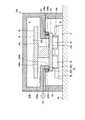
次に、第1空間Pのシール構造について説明する。図1及び図2に示すように、本実施形態の位置決め装置10において、板状部材20aとステージ30との間に隙間24が設けられる。隙間24に給気ポンプ50から気体が供給されることで、板状部材20aとステージ30との間が封止(シール)される。 Next, the seal structure of the first space P will be described. As shown in FIGS. 1 and 2, in the
隙間24は、第1隙間24Aと第2隙間24Bとを含む。板状部材20aは、ステージ30に向かい突出する突出部20bが設けられている。突出部20bは、板状部材20aと一体に形成されている。これに限られず、突出部20bは、板状部材20aと別部材で設けてもよい。また、板状部材20aの上面において、突出部20bよりも径方向外側にシール部材22が配置される。シール部材22の上面22cと、ステージ30の第1面30aとが第1隙間24Aを有して対向する。後述するように、突出部20b及びシール部材22は、孔部20cを囲む環状の部材である。 The
突出部20bは、板状部材20aの上面に設けられ、板状部材20aの孔部20c側の端部に設けられる。突出部20bの側面20dは、板状部材20aの端面と連続している。これに限られず、突出部20bはステージ30の第1面30aと対向する位置に配置されていればよく、突出部20bの側面20dが、板状部材20aの端面よりも径方向外側に位置してもよい。突出部20bの上面20eと、ステージ30の第1面30aとが第2隙間24Bを有して対向する。このように、突出部20bとシール部材22とを設けているため、第1隙間24A及び第2隙間24Bの寸法の管理を容易に行うことができる。本実施形態では、第2隙間24Bの間隔t2は、第1隙間24Aの間隔t1よりも大きくなっている。第1隙間24Aの間隔t1は、例えば、数十μm以上、1.0mm以下程度である。第2隙間24Bの間隔t2は、例えば、数百μm以上、数mm以下程度である。また、板状部材20aは、突出部20bが設けられているので、強度が向上する。したがって、板状部材20aの変形が抑制され、第1隙間24A及び第2隙間24Bの寸法の変動を抑制することができる。 The protruding
図2に示すように、シール部材22は、第1側面22dと第2側面22eとを有している。第1側面22d及び第2側面22eは、突出部20bの外側面20fと隙間を有して対向する。第1側面22dは板状部材20a側に配置され、第2側面22eはステージ30側に配置される。第1側面22dは、第2側面22eよりも突出部20bから離れた位置に設けられ、第1側面22dと第2側面22eとで段差が形成される。 As shown in FIG. 2, the
シール部材22の第1側面22dと、突出部20bの外側面20fとで、給気溝22aが構成される。シール部材22の第2側面22eと、突出部20bの外側面20fとの隙間によりスリット状の給気部22b(第3隙間)が構成される。給気部22bは、給気溝22aと連続して、給気溝22aからステージ30に向かう方向に延びて、隙間24に開口する。第1隙間24Aは、給気部22bよりも第1空間P側に配置される。第2隙間24Bは、給気部22bよりも第2空間R側に配置される。 The
給気部22bは、第2側面22eと外側面20fとの間の第3隙間の間隔t3が小さい絞り部であり、第3隙間の間隔t3は、給気溝22aの幅(第1側面22dと外側面20fとの間隔)よりも小さくなっている。給気部22bの第3隙間の間隔t3は、例えば、数μm以上、数十μm以下程度である。給気部22bは、突出部20bとシール部材22との2つの部材を対向させて設けられるため、一つの部材に絞り部を形成する場合に比べて、第3隙間の間隔t3の管理が比較的容易である。また、シール部材22に段差を形成することで給気溝22aが形成されるため、給気部22b及び給気溝22aを容易に形成することができる。 The
図1に示すように、給気ポンプ50から給気溝22aに気体が供給される。気体は、給気溝22aから給気部22bを通って隙間24に供給される。給気部22bの第3隙間の間隔t3は、第1隙間24Aの間隔t1よりも小さく、かつ、第2隙間24Bの間隔t2よりも小さくなっている。 As shown in FIG. 1, gas is supplied from the
ここで、給気部22bの第3隙間の間隔t3は、シール部材22の第2側面22eと垂直な方向における、シール部材22の第2側面22eと突出部20bの外側面20fとの距離である。また、第1隙間24Aの間隔t1は、シール部材22の上面22cと垂直な方向における、シール部材22の上面22cと、ステージ30の第1面30aとの距離である。また、第2隙間24Bの間隔t2は、突出部20bの上面20eと垂直な方向における、突出部20bの上面20eと、ステージ30の第1面30aとの距離である。 Here, the interval t3 of the third gap of the
給気部22bの隙間が小さくなっているので、給気ポンプ50から供給された気体は、給気部22bを通過する際に流速が大きくなる。このため、エゼクタ効果により、給気部22bの近傍の第1隙間24A及び第2隙間24Bで、第1空間Pから給気部22bに向かう負圧が発生する。この負圧により、図2に示すように、第1隙間24Aにおいて、第1空間Pの気体が矢印F1に示す方向に流れる。 Since the gap between the
上述のように、第2隙間24Bの間隔t2は、第1隙間24Aの間隔t1よりも大きくなっている。このため、第2隙間24Bを通る気体の抵抗が、第1隙間24Aを通る気体の抵抗よりも小さくなる。したがって、給気部22bから供給された気体は、抵抗が小さい第2隙間24Bを通って矢印F2に示す方向に流れる。 As described above, the interval t2 of the
以上のように、給気部22bから供給された気体は、第2隙間24Bを通って第2空間Rに流入する。また、エゼクタ効果により発生した負圧により、第1空間Pの気体が第1隙間24A及び第2隙間24Bを通って第2空間Rに流入する。これにより、本実施形態の位置決め装置10によれば、ワークの位置決めや検査を行う第1空間Pへの気体の流入が抑制される。したがって、第1空間Pにおける気流の乱れが抑制され、第1空間P内の圧力分布の発生や温度分布の発生を抑制することができる。 As described above, the gas supplied from the
また、本実施形態の位置決め装置10は、ステージ30、突出部20b及びシール部材22により、第1隙間24A、第2隙間24B及び給気部22bを設け、給気部22bに陽圧の気体を供給することで第1空間Pのシール構造が実現できる。このため、第1空間Pが減圧空間等の環境であっても、排気式シールや、磁気シールなどを設けることなく、給気部22bに気体を供給するのみで第1空間Pのシールが可能である。すなわち、位置決め装置10の小型化を図ることが可能である。 Further, the
さらに、第1隙間24A、第2隙間24B及び給気部22bを設け、給気部22bに陽圧の気体を供給することで、第1空間Pの気体を、第1隙間24A、第2隙間24Bを通って第2空間R側に流入させる負圧を発生させることができる。つまり、第1隙間24A、第2隙間24B及び給気部22bが負圧発生機構として機能するので、負圧を発生させるポンプや、第1空間Pの気体を吸気するための配管や溝部を設ける必要がない。したがって、簡便な構成で負圧発生機構を実現することができる。 Further, by providing the
図3は、図1のIII−III’線に沿う断面図である。図3に示すように、突出部20b及びシール部材22は、連結軸32の中心軸Zrを中心とした環状の部材である。本実施形態において、突出部20b及びシール部材22は、平面視において、略矩形状である。ただし、これに限定されず、突出部20b及びシール部材22は、円形、正方形等、他の形状であってもよい。シール部材22は、突出部20bよりも径方向の外側に配置される。上述したように、シール部材22の第2側面22eと、突出部20bの外側面20fとの隙間により給気部22bが構成される。給気部22bは、スリット状であり、突出部20b及びシール部材22の周方向に沿って、環状に連続して設けられる。 FIG. 3 is a sectional view taken along the line III-III′ of FIG. 1. As shown in FIG. 3, the
なお、図3では図示を省略するが、図1及び図2に示す、給気溝22a、第1隙間24A及び第2隙間24Bも、突出部20b及びシール部材22の周方向に沿って、連続して設けられる。 Although not shown in FIG. 3, the
このような構成により、給気部22bに気体が供給されることで、第1空間Pの気体を第2空間R側に流入させる負圧が、給気部22bの周方向に沿って全周に発生する。第1隙間24A及び第2隙間24Bを通って第2空間Rに流入する気体の流れは、給気部22bから径方向の内側に、連結軸32の中心軸Zrに向かう方向に発生する。給気部22bの第3隙間の間隔t3(図2参照)を周方向に沿って等しい大きさとなるようにすることで、給気部22bの周方向に沿って均等に負圧が発生する。したがって、第1空間Pの気体は、周方向に沿った第1隙間24Aの周方向の全体に流入する。 With such a configuration, the gas is supplied to the
したがって、ワークの位置決めや検査を行う第1空間Pへの気体の流入が確実に抑制される。また、周方向の一部に負圧発生機構を構成した場合に比べて、第1空間Pにおける気流の乱れが抑制される。 Therefore, the inflow of gas into the first space P where the workpiece is positioned and inspected is reliably suppressed. Further, the turbulence of the airflow in the first space P is suppressed as compared with the case where the negative pressure generating mechanism is formed in a part of the circumferential direction.
また、給気溝22aは給気部22bに沿って全周に設けられている。上述したように、給気溝22aの隙間の間隔、すなわち、図2に示すシール部材22の第1側面22dと、突出部20bの外側面20fとの間隔は、給気部22bの第3隙間の間隔t3よりも大きくなっている。給気溝22aを通る気体の抵抗が小さくなっているため、給気部22bの周方向に沿って均等に気体が供給される。したがって、給気ポンプ50からの気体は、給気溝22aの1か所、又は複数箇所に供給されればよく、筐体20に設けられる気体供給用の通路の数を少なくして、構成を簡便にすることができる。 Further, the
以上説明したように、本実施形態の位置決め装置10は、筐体20に囲まれた第1空間Pと、第1空間Pと異なる第2空間Rとを区切る板状部材20aと、板状部材20aに設けられた孔部20cを覆うとともに、板状部材20aの一方の面と隙間24を有して対向するステージ30と、板状部材20aの孔部20cに挿通され、ステージ30と連結される連結軸32と、板状部材20aの孔部20cよりも外側において隙間24に開口し、隙間24へ気体を供給することより、第1空間Pの気体を、隙間24を通って第2空間R側に流入させる給気部22bと、を有する。 As described above, the
この構成によれば、板状部材20aとステージ30との隙間24に、給気部22bから気体が供給されることにより、第1空間Pがシールされる。この給気部22bからの気体の供給により、第1空間Pの気体が隙間24を通って第2空間R側に流入する負圧が発生する。また、隙間24の気体を排出するための配管や通路等を設ける必要がない。このため、簡便な構成で、ワークの位置決めや検査を行うための第1空間Pに気体が流入することを抑制できる。 According to this configuration, the first space P is sealed by supplying the gas from the
なお、本実施形態において、第2隙間24Bの間隔t2が、第1隙間24Aの間隔t1よりも大きくなっている。これに限られず、第2隙間24Bの間隔t2が、第1隙間24Aの間隔t1と等しい、又は第1隙間24Aの間隔t1よりも小さい場合であってもよい。この場合、第1隙間24Aの径方向の長さを第2隙間24Bの径方向の長さよりも長くすることで、第1隙間24Aを通る気体の抵抗を大きくすることができる。 In the present embodiment, the interval t2 of the
(第2の実施形態)
図4は、第2の実施形態に係る位置決め装置のシール構造を示す断面図である。なお、上述した実施形態と同様の構成については、同じ符号を付して説明を省略する場合がある。本実施形態の位置決め装置10Aは、給気溝22h及び給気部22iがシール部材22と板状部材20aとの間に設けられている点が異なる。(Second embodiment)
FIG. 4 is a cross-sectional view showing the seal structure of the positioning device according to the second embodiment. In addition, about the structure similar to embodiment mentioned above, the same code|symbol may be attached|subjected and description may be abbreviate|omitted. The
本実施形態において、シール部材22は、下面22fと、下面22fよりも上方に凹む凹部22gとを有する。下面22fは、板状部材20aの上面20gと第4隙間を有して対向しており、シール部材22の下面22fと、板状部材20aの上面20gとの間に給気部22iが構成される。また、シール部材22の凹部22gと、板状部材20aの上面20gとの間に給気溝22hが構成される。給気部22iは、給気溝22hと連続して設けられており、給気溝22hに対して、径方向の内側に向かって延びている。給気部22iは、給気溝22hよりも、板状部材20aの上面20gとの隙間が小さい絞り部となっている。 In the present embodiment, the
給気部22iの第4隙間の間隔t4は、シール部材22の第2側面22eと突出部20bの外側面20fとの間に形成される第3隙間の間隔t3よりも小さくなっている。すなわち、シール部材22と突出部20bとの間の第3隙間の間隔t3は、第4隙間の間隔t4よりも大きくすることができ、第3隙間の間隔t3の寸法管理が容易である。したがって、本実施形態の位置決め装置10Aは、容易に製造することができる。本実施形態では、第1隙間24Aの間隔t1は、例えば、数十μm以上、1.0mm以下程度である。第2隙間24Bの間隔t2は、例えば、数百μm以上、数mm以下程度である。第3隙間の間隔t3は、例えば、数百μm以上、1.0mm以下程度である。第4隙間の間隔t4は、例えば、数μm以上、数十μm以下程度である。 The interval t4 of the fourth gap of the
給気溝22hは、給気ポンプ50(図1参照)からの気体が供給される。給気部22iの隙間が小さくなっているので、給気ポンプ50から供給された気体は、給気部22iを通過する際に流速が大きくなる。給気部22iを通過した気体は、シール部材22と突出部20bとの間の第3隙間を通って、隙間24に供給される。本実施形態においても、エゼクタ効果により負圧が発生し、第1空間Pの気体が第1隙間24A及び第2隙間24Bを通って第2空間Rに流入する。また、第2隙間24Bの間隔t2は、第1隙間24Aの間隔t1よりも大きくなっている。このため、給気部22iから供給された気体は、第2隙間24Bを通って第2空間Rに流入する。これにより、本実施形態の位置決め装置10Aにおいても、ワークの位置決めや検査を行う第1空間Pへの気体の流入が抑制される。 Gas from the air supply pump 50 (see FIG. 1) is supplied to the
(第3の実施形態)
図5は、第3の実施形態に係る回転機構を模式的に示す断面図である。図6は、第3の実施形態に係る回転機構のシール構造を示す断面図である。回転機構1は、回転を伝達する機械要素であり、例えば、工作機械、真空チャンバ等の特殊環境下で使用される搬送装置、半導体製造装置又はフラットパネルディスプレイ製造装置等に適用される。ここでは、一例として、回転機構1が、スピンドルを回転軸として備えるスピンドルユニットである場合を説明するが、回転機構1の適用対象はこれに限定されるものではない。(Third Embodiment)
FIG. 5 is a sectional view schematically showing the rotating mechanism according to the third embodiment. FIG. 6 is a sectional view showing the seal structure of the rotating mechanism according to the third embodiment. The
回転機構1は、ハウジング2と、シャフト4と、軸受6A、6Bと、回転体としての回転部材5と、筐体20Aと、を含む。ハウジング2は、軸受6A、6B及び電動機3等を収容する部材である。本実施形態において、ハウジング2は、第1部材2Aと、第2部材2Bとを有する。第1部材2Aは筒状の部材であり、第1部材2Aの一端部に筐体20Aの板状部材20Aaが設けられ、他端部に第2部材2Bが設けられる。第1部材2A及び第2部材2Bは、ハウジング2の一部である。本実施形態において、第1部材2Aは円筒形状の部材であり、一端部から他端部、すなわち筐体20Aから第2部材2Bに向かう貫通孔2Iを有している。貫通孔2Iは、板状部材20Aaの孔部20Acと連続して設けられる。 The
第2部材2Bは、平面視において円形の板状の部材であり、第1部材2Aの開口を覆って設けられている。なお、第2部材2Bの形状は、円形に限定されない。本実施形態において、筐体20Aで囲まれる空間、すなわち、板状部材20Aaを含む筐体20Aと回転部材5とで囲まれる空間が第1空間Pである。また、ハウジング2の内部、すなわち第1部材2Aと第2部材2Bと回転部材5とで囲まれる空間が第2空間Rである。第2部材2Bに設けられた貫通孔に給電ケーブル3Cが挿通される。給電ケーブル3Cは、ハウジング2の内部の第2空間Rに設けられる電動機3に電力を供給する。 The
シャフト4は、回転機構1の出力軸であり、板状部材20Aaの孔部20Acに挿入されて、ハウジング2の貫通孔2Iに挿通される。シャフト4は、第1空間Pの気体を第2空間Rに排気するための排気孔8が設けられている。排気溝8Aがシャフト4の端部4TA側の外周面に開口している。排気孔8は、排気溝8Aに接続され、シャフト4の内部を軸方向に沿って延びて、シャフト4の他端側の面に開口する。また、シャフト4の端部4TA側に環状のスペーサ9が設けられている。排気溝8Aは、スペーサ9に設けられた貫通孔9Aと対向する位置に設けられる。 The
軸受6A、6Bは、ハウジング2の内部に設置されてシャフト4を回転可能に支持する。本実施形態において、シャフト4は、2個の軸受6A、6Bによってハウジング2に支持されるが、軸受の数は2個に限定されない。 The
軸受6A、6Bは、それぞれ、外輪6aと、転動体6bと、内輪6cとを含む。内輪6cは、外輪6aの径方向内側に配置される。転動体6bは、外輪6aと内輪6cとの間に配置される。軸受6A、6Bは、ハウジング2の第1部材2Aの内壁2Wに外輪6aが接している。このような構造により、軸受6A、6Bは、ハウジング2に取り付けられる。本実施形態において、軸受6A、6Bは、いずれも転がり軸受である。両方の軸受6A、6Bは、いずれも玉軸受であるが、転がり軸受としての軸受6A、6Bの種類は玉軸受に限定されない。また、本実施形態において、軸受6A、6Bは、滑り軸受であってもよい。 The
本実施形態において、軸受6Aの内輪6cが、シャフト4の端部4TA側に設けられた環状のスペーサ9と接している。軸受6Aは、外輪6aがハウジング2の第1部材2Aに接する。また、軸受6Aの内輪6cと軸受6Bの内輪6cとが接する。軸受6Bの内輪6cに環状のスペーサ4Sが接触した状態で、スペーサ4S側からシャフト4にロックナット4Nがねじ込まれる。 In the present embodiment, the
ハウジング2の内部には、電動機3が設けられている。電動機3は軸受6A、6Bよりもシャフト4の他端側、すなわち第2部材2B側に配置される。電動機3は、ローター3Rと、ローター3Rの径方向外側に設けられたステーター3Sとを含む。ステーター3Sは、第1部材2Aの内壁2Wに取り付けられる。ローター3Rは、シャフト4の他端部に連結される。このような構造により、ローター3Rとシャフト4と回転部材5とは、一体となって回転中心軸Zrの周りを回転する。本実施形態において、電動機3の形式は問わない。 An
回転部材5は、第1空間Pに配置される。回転部材5は、シャフト4の端部4TAに設けられてシャフト4とともに回転する。回転部材5は、第1面5aがシャフト4の端部4TAに接続され、第1面5aとは反対側の第2面5bにワーク等の物体が載置される。本実施形態において、回転部材5は、板状の部材であって平面視が円形である。回転部材5は、板状部材20Aaの孔部20Acよりも径方向外側まで張り出している。回転部材5の、孔部20Acの径方向外側まで張り出した部分は、板状部材20Aaと所定の隙間25を有して対向している。回転部材5と板状部材20Aaとの隙間25により、回転機構1のシール構造が構成される。 The rotating
図6に示すように、板状部材20Aaは、回転部材5に向かい突出する突出部20Abを有する。突出部20Abの上面20Aeと、回転部材5の第1面5aとが第2隙間25Bを有して対向する。また、板状部材20Aaの上面において、突出部20Abよりも径方向の外側にシール部材22Aが配置される。シール部材22Aの上面22Acと、回転部材5の第1面5aとが第1隙間25Aを有して対向する。 As shown in FIG. 6, the plate-shaped member 20Aa has a protruding portion 20Ab protruding toward the rotating
シール部材22Aの第1側面22Adと、突出部20Abの外側面20Afとで、給気溝22Aaが構成される。シール部材22Aの第2側面22Aeと、突出部20Abの外側面20Afとの隙間によりスリット状の給気部22Ab(第3隙間)が構成される。給気部22Abは、給気溝22Aaと連続して、給気溝22Aaから回転部材5に向かう方向に延びて、隙間25に開口する。第1隙間25Aは、給気部22Abよりも第1空間P(図5参照)側に配置される。第2隙間25Bは、給気部22Abよりも第2空間R(図5参照)側に配置される。 The first side surface 22Ad of the
給気部22Abは、給気溝22Aaよりも突出部20Abとの隙間の間隔が小さい絞り部となっている。給気部22Abは、突出部20Abとシール部材22Aとの2つの部材を対向させて設けられるため、一つの部材に絞り部を形成する場合に比べて、第3隙間の間隔ta3の管理が比較的容易である。また、シール部材22Aに段差を形成することで給気溝22Aaが形成されるため、給気部22Ab及び給気溝22Aaを容易に形成することができる。 The air supply portion 22Ab is a throttle portion having a smaller gap between the air supply groove 22Aa and the protruding portion 20Ab. Since the air supply portion 22Ab is provided so that the two members of the protruding portion 20Ab and the
本実施形態の回転機構1において、給気ポンプ50(図5参照)から給気溝22Aaに気体が供給される。気体は、給気溝22Aaから給気部22Abを通って隙間25に供給される。給気部22Abの第3隙間の間隔ta3は、第1隙間25Aの間隔ta1よりも小さく、かつ、第2隙間25Bの間隔ta2よりも小さくなっている。給気部22Abの第3隙間の間隔ta3は、例えば、数μm以上、数十μm以下程度である。 In the
給気部22Abの隙間が小さくなっているので、給気ポンプ50から供給された気体は、給気部22Abを通過する際に流速が大きくなる。このため、エゼクタ効果により、給気部22Abの近傍の第1隙間25A及び第2隙間25Bで、第1空間Pから給気部22Abに向かう負圧が発生する。この負圧により、図6に示すように、第1隙間25Aにおいて、第1空間Pの気体が矢印Fa1に示す方向に流れる。 Since the gap between the air supply units 22Ab is small, the gas supplied from the
本実施形態においても、第2隙間25Bの間隔ta2は、第1隙間25Aの間隔ta1よりも大きくなっている。このため、第2隙間25Bを通る気体の抵抗が、第1隙間25Aを通る気体の抵抗よりも小さくなる。したがって、給気部22Abから供給された気体は、抵抗が小さい第2隙間25Bを通って矢印Fa2に示す方向に流れる。 Also in this embodiment, the interval ta2 of the
以上のように、給気部22Abから供給された気体は、第2隙間25Bを通ってシャフト4側に流入する。第2隙間25Bを通過した気体は、上述したスペーサ9の貫通孔9A、シャフト4に設けられた排気溝8A、排気孔8(図5参照)を介して、第2空間Rに流入する。また、エゼクタ効果により発生した負圧により、第1空間Pの気体が第1隙間25A及び第2隙間25Bを通って第2空間Rに流入する。これにより、本実施形態の回転機構1によれば、ワークの位置決めや検査を行う第1空間Pへの気体の流入が抑制される。したがって、第1空間Pにおける気流の乱れが抑制され、第1空間P内の圧力分布の発生や温度分布の発生を抑制することができる。 As described above, the gas supplied from the air supply unit 22Ab flows into the
また、本実施形態の回転機構1は、回転部材5、突出部20Ab及びシール部材22Aにより、第1隙間25A、第2隙間25B及び給気部22Abを設け、給気部22Abに陽圧の気体を供給することで第1空間Pのシール構造が実現できる。このため、第1空間Pが減圧空間等の環境であっても、排気式シールや、磁気シールなどを設けることなく、給気部22Abに気体を供給するのみで第1空間Pのシールが可能である。すなわち、回転機構1の小型化を図ることが可能である。 In addition, the
(第4の実施形態)
図7は、第4の実施形態に係る位置決め装置を模式的に示す断面図である。図8は、第4の実施形態に係る位置決め装置のシール構造を示す断面図である。本実施形態の位置決め装置10Bは、第1の実施形態と同様に、1軸移動可能なステージ30によりワークWの位置決め等を行うことができる。板状部材20Baの孔部20Bcに連結軸32が挿通されている。ステージ30は連結軸32を介して駆動ステージ34に接続される。駆動ステージ34は、上述したように図示しない外部の駆動部から駆動力が伝達される。駆動ステージ34は、リニアベアリング35、35、ガイド部材36、ベース部材37等を含む駆動機構により1軸移動可能となっている。駆動ステージ34の移動に伴って、ステージ30が1軸移動可能となっている。(Fourth Embodiment)
FIG. 7 is a sectional view schematically showing the positioning device according to the fourth embodiment. FIG. 8 is a sectional view showing the seal structure of the positioning device according to the fourth embodiment. The
本実施形態の位置決め装置10Bにおいて、駆動ステージ34は、板状部材20Baとの間に所定の隙間26を有して設けられる。図7及び図8に示すように、板状部材20Baは、駆動ステージ34に向かい突出する突出部20Bbを有する。突出部20Bbの下面20Beと、駆動ステージ34の第1面34aとが第1隙間26Aを有して対向する。また、板状部材20Baの下面において、突出部20Bbよりも径方向の外側にシール部材22Bが配置される。シール部材22Bの下面22Bcと、駆動ステージ34の第1面34aとが第2隙間26Bを有して対向する。駆動ステージ34の第2面34bには、リニアベアリング35、35が連結されている。本発明の「可動部」は、本実施形態における駆動ステージ34に対応する。 In the
なお、本実施形態において、第1空間Pは、板状部材20Ba及び突出部20Bbを含む筐体20Bと、駆動ステージ34とで囲まれた空間である。また、第2空間Rは、定盤55と、支持部28と、板状部材20Baと駆動ステージ34とで囲まれた空間である。ここで筐体20Bは、板状部材20Ba及び突出部20Bbを含むとしたが、板状部材20Ba及び突出部20Bbは、筐体20Bと別体で設けてもよい。本実施形態では、第1空間Pの内部に連結軸32及びステージ30が配置される。ステージ30の第1面30aに連結軸32が連結され、第2面30bにワークW等が載置される。ステージ30の第1面30aと板状部材20Baとの間には、シール部材22B等の構造体は設けられていない。 In the present embodiment, the first space P is a space surrounded by the
シール部材22Bの第1側面22Bdと、突出部20Bbの外側面20Bfとで、給気溝22Baが構成される。シール部材22Bの第2側面22Beと、突出部20Bbの外側面20Bfとの隙間によりスリット状の給気部22Bb(第3隙間)が構成される。給気部22Bbは、給気溝22Baと連続して、給気溝22Baから駆動ステージ34に向かう方向に延びて、隙間26に開口する。第1隙間26Aは、給気部22Bbよりも第1空間P(図7参照)側に配置される。第2隙間26Bは、給気部22Bbよりも第2空間R(図7参照)側に配置される。 The first side surface 22Bd of the
上述したエゼクタ効果により、給気部22Bbの近傍の第1隙間26A及び第2隙間26Bで、第1空間Pから給気部22Bbに向かう負圧が発生する。この負圧により、図8に示すように、第1隙間26Aにおいて、第1空間Pの気体が矢印Fb1に示す方向に流れる。By ejector effect mentionedabove, in the
本実施形態においても、第2隙間26Bの間隔tb2は、第1隙間26Aの間隔tb1よりも大きくなっている。このため、第2隙間26Bを通る気体の抵抗が、第1隙間26Aを通る気体の抵抗よりも小さくなる。したがって、給気部22Bbから供給された気体は、抵抗が小さい第2隙間26Bを通って矢印Fb2に示す方向に流れる。 Also in this embodiment, the interval tb2 of the
以上のように、給気部22Bbから供給された気体は、第2隙間26Bを通って第2空間Rに流入する。また、エゼクタ効果により発生した負圧により、第1空間Pの気体が第1隙間26A及び第2隙間26Bを通って第2空間Rに流入する。これにより、本実施形態の位置決め装置10Bによれば、ワークWの位置決めや検査を行う第1空間Pへの気体の流入が抑制される。したがって、第1空間Pにおける気流の乱れが抑制され、第1空間P内の圧力分布の発生や温度分布の発生を抑制することができる。 As described above, the gas supplied from the air supply unit 22Bb flows into the second space R through the
また、本実施形態の位置決め装置10Bは、駆動ステージ34、突出部20Bb及びシール部材22Bにより、第1隙間26A、第2隙間26B及び給気部22Bbを設け、給気部22Bbに陽圧の気体を供給することで第1空間Pのシール構造が実現できる。このように、ワークWを載置し、位置決め等を行うためのステージ30と異なる部材である駆動ステージ34によりシール構造を設けてもよい。本実施形態においても、第1空間Pが減圧空間等の環境であっても、排気式シールや、磁気シールなどを設けることなく、給気部22Bbに気体を供給するのみで第1空間Pのシールが可能である。すなわち、位置決め装置10Bの小型化を図ることが可能である。 Further, the
本実施形態の位置決め装置10Bにおいて、駆動ステージ34は、第2空間Rに配置され、板状部材20Baの第2空間R側の面と隙間26を有して対向する。板状部材20Baの第2空間R側に設けられた隙間26によりシール構造が構成される。このため、ステージ30の交換等の作業を行う場合であっても、シールを構成する突出部20Bb、シール部材22B、駆動ステージ34の取り外し等が不要であるため、各隙間の間隔tb1、tb2、tb3が維持される。したがって、メンテナンス等の作業を容易に行うことができる。 In the
以上、第1の実施形態から第4の実施形態を説明したが、前述した内容により第1の実施形態から第4の実施形態が限定されるものではない。また、前述した構成要素には、当業者が容易に想定できるもの、実質的に同一のもの、いわゆる均等の範囲のものが含まれる。さらに、前述した構成要素は適宜組み合わせることが可能である。さらに、第1の実施形態から第4の実施形態の要旨を逸脱しない範囲で構成要素の種々の省略、置換及び変更のうち少なくとも1つを行うことができる。 The first to fourth embodiments have been described above, but the first to fourth embodiments are not limited by the above contents. In addition, the above-described constituent elements include those that can be easily conceived by those skilled in the art, substantially the same elements, and so-called equivalent ranges. Furthermore, the components described above can be combined appropriately. Furthermore, at least one of various omissions, replacements, and changes of the constituent elements can be performed without departing from the spirit of the first to fourth embodiments.
1 回転機構
2 ハウジング
3 電動機
4 シャフト
5 回転部材
6A、6B 軸受
10、10A、10B 位置決め装置
20、20A、20B 筐体
20a、20Aa、20Ba 板状部材
20b、20Ab、20Bb 突出部
20c、20Ac、20Bc 孔部
22、22A、22B シール部材
22a、22h、22Aa 給気溝
22b、22i、22Ab 給気部
22g 凹部
24、25、26 隙間
24A、25A、26A 第1隙間
24B、25B、26B 第2隙間
28 支持部
30 ステージ
32 連結軸
34 駆動ステージ
50 給気ポンプ
55 定盤
P 第1空間
R 第2空間1 Rotating
Claims (7)
Translated fromJapanese前記第1空間に配置され、前記板状部材に設けられた孔部を覆うとともに、前記板状部材の前記第1空間側の面と隙間を有して対向する可動部と、
前記板状部材の前記孔部に挿通され、前記可動部と連結される連結軸と、
前記板状部材の前記孔部よりも外側において前記隙間に開口し、前記隙間へ気体を供給することにより、前記第1空間の気体を、前記隙間を通って前記第2空間側に流入させる給気部と、を有し、
前記隙間は、前記給気部よりも前記第1空間側の第1隙間と、前記給気部よりも前記第2空間側の第2隙間とを含み、
前記板状部材は、前記可動部側に突出する突出部が設けられ、
前記突出部の径方向外側の面と第3隙間を有して対向するシール部材が設けられ、
前記シール部材と前記可動部との間に前記第1隙間が設けられ、前記突出部と前記可動部との間に前記第2隙間が設けられ、
前記給気部は、前記第3隙間を含み、
前記第2隙間の間隔は、前記第1隙間の間隔よりも大きく、
前記第3隙間の間隔は、前記第1隙間の間隔よりも小さく、かつ、前記第2隙間の間隔よりも小さい位置決め装置。A plate-shaped member for partitioning a first space surrounded by a housing and a second space different from the first space;
A movable part that is arranged in the first space, covers the hole provided in the plate-shaped member, and faces the surface ofthe plate-shaped member onthe first space side with a gap;
A connecting shaft that is inserted into the hole of the plate-shaped member and that is connected to the movable portion,
The gas in the first space is introduced into the gap outside the hole of the plate-like member and is supplied to the gap to allow the gas in the first space to flow into the second space through the gap.possess a vaporportion,
The gap includes a first gap closer to the first space than the air supply unit, and a second gap closer to the second space than the air supply unit,
The plate-shaped member is provided with a protrusion that protrudes toward the movable portion,
A seal member is provided that faces the radially outer surface of the protrusion with a third gap therebetween.
The first gap is provided between the seal member and the movable portion, and the second gap is provided between the protruding portion and the movable portion,
The air supply unit includes the third gap,
The interval of the second gap is larger than the interval of the first gap,
A positioning device in whichthe third gap is smaller than the first gap and smaller than the second gap .
前記第4隙間は、前記第1空間に開口しないで設けられ、
前記給気部は、前記第4隙間を含む請求項1から請求項3のいずれか1項に記載の位置決め装置。A part of the seal member faces the one surface of the plate-like member with a fourth gap,
The fourth gap is provided without opening in the first space,
The positioning device according toany one of claims 1 to 3 , wherein the air supply unit includes the fourth gap.
前記第2空間に配置され、前記板状部材に設けられた孔部を覆うとともに、前記板状部材の前記第2空間側の面と隙間を有して対向する可動部と、
前記板状部材の前記孔部に挿通され、前記可動部と連結される連結軸と、
前記板状部材の前記孔部よりも外側において前記隙間に開口し、前記隙間へ気体を供給することにより、前記第1空間の気体を、前記隙間を通って前記第2空間側に流入させる給気部と、
前記第1空間に設けられ、前記連結軸を介して前記可動部と連結されており、ワークを移動させるためのステージと、を有し、
前記隙間は、前記給気部よりも前記第1空間側の第1隙間と、前記給気部よりも前記第2空間側の第2隙間とを含み、
前記板状部材は、前記可動部側に突出する突出部が設けられ
前記突出部の径方向外側の面と第3隙間を有して対向するシール部材が設けられ、
前記突出部と前記可動部との間に前記第1隙間が設けられ、前記シール部材と前記可動部との間に前記第2隙間が設けられ、
前記給気部は、前記第3隙間を含み、
前記第2隙間の間隔は、前記第1隙間の間隔よりも大きく、
前記第3隙間の間隔は、前記第1隙間の間隔よりも小さく、かつ、前記第2隙間の間隔よりも小さい位置決め装置。A plate-shaped member for partitioning a first space surrounded by a housing and a second space different from the first space;
A movable portion that is disposed in the second space, covers the hole provided in the plate-shaped member, and faces the surface of the plate-shaped member on the second space side with a gap;
A connecting shaft that is inserted into the hole of the plate-shaped member and that is connected to the movable portion,
The gas in the first space is introduced into the gap outside the hole of the plate-like member and is supplied to the gap to allow the gas in the first space to flow into the second space through the gap. Kibe,
A stagewhich is provided in the first space,is connected to the movable portion via the connecting shaft, and is for movinga work;
The gap includes a first gap closer to the first space than the air supply unit, and a second gap closer to the second space than the air supply unit,
The plate-shaped member is provided with a protrusion that protrudes toward the movable portion.
A seal member is provided that faces the radially outer surface of the protrusion with a third gap therebetween.
The first gap is provided between the protrusion and the movable part, and the second gap is provided between the seal member and the movable part.
The air supply unit includes the third gap,
The interval of the second gap is larger than the interval of the first gap,
A positioning device in whichthe third gap is smaller than the first gap and smaller than the second gap .
前記板状部材に設けられた孔部を覆うとともに、前記板状部材の前記第1空間側の面と隙間を有して対向する回転部材と、
前記板状部材の前記孔部に挿通され、前記回転部材と連結される連結軸と、
前記第2空間に設置されて前記連結軸を回転可能に支持する軸受と、
前記板状部材の前記孔部よりも外側において前記隙間に開口し、前記隙間へ気体を供給することにより、前記第1空間の気体を、前記隙間を通って前記第2空間側に流入させる給気部と、を有し、
前記隙間は、前記給気部よりも前記第1空間側の第1隙間と、前記給気部よりも前記第2空間側の第2隙間とを含み、
前記板状部材は、前記可動部側に突出する突出部が設けられ
前記突出部の径方向外側の面と第3隙間を有して対向するシール部材が設けられ、
前記シール部材と前記可動部との間に前記第1隙間が設けられ、前記突出部と前記可動部との間に前記第2隙間が設けられ、
前記給気部は、前記第3隙間を含み、
前記第2隙間の間隔は、前記第1隙間の間隔よりも大きく、
前記第3隙間の間隔は、前記第1隙間の間隔よりも小さく、かつ、前記第2隙間の間隔よりも小さい回転機構。A plate-shaped member for partitioning a first space surrounded by a housing and a second space different from the first space;
A rotating member that covers the hole provided in the plate-shaped member and that faces the surface of the plate-shaped member on the first space side with a gap,
A connecting shaft that is inserted into the hole of the plate-shaped member and that is connected to the rotating member,
A bearing installed in the second space to rotatably support the connecting shaft;
The gas in the first space is introduced into the gap outside the hole of the plate-like member and is supplied to the gap to allow the gas in the first space to flow into the second space through the gap.possess a vaporportion,
The gap includes a first gap closer to the first space than the air supply unit, and a second gap closer to the second space than the air supply unit,
The plate-shaped member is provided with a protrusion that protrudes toward the movable portion.
A seal member is provided that faces the radially outer surface of the protrusion with a third gap therebetween.
The first gap is provided between the seal member and the movable portion, and the second gap is provided between the protruding portion and the movable portion,
The air supply unit includes the third gap,
The interval of the second gap is larger than the interval of the first gap,
A rotation mechanism in whichthe interval of the third gap is smaller than the interval of the first gap and smaller than the interval of the second gap .
Priority Applications (1)
| Application Number | Priority Date | Filing Date | Title |
|---|---|---|---|
| JP2016079625AJP6707964B2 (en) | 2016-04-12 | 2016-04-12 | Positioning device and rotation mechanism |
Applications Claiming Priority (1)
| Application Number | Priority Date | Filing Date | Title |
|---|---|---|---|
| JP2016079625AJP6707964B2 (en) | 2016-04-12 | 2016-04-12 | Positioning device and rotation mechanism |
Publications (2)
| Publication Number | Publication Date |
|---|---|
| JP2017191174A JP2017191174A (en) | 2017-10-19 |
| JP6707964B2true JP6707964B2 (en) | 2020-06-10 |
Family
ID=60085228
Family Applications (1)
| Application Number | Title | Priority Date | Filing Date |
|---|---|---|---|
| JP2016079625AActiveJP6707964B2 (en) | 2016-04-12 | 2016-04-12 | Positioning device and rotation mechanism |
Country Status (1)
| Country | Link |
|---|---|
| JP (1) | JP6707964B2 (en) |
Families Citing this family (2)
| Publication number | Priority date | Publication date | Assignee | Title |
|---|---|---|---|---|
| JP6707963B2 (en)* | 2016-04-12 | 2020-06-10 | 日本精工株式会社 | Positioning device |
| JP7033168B2 (en)* | 2020-06-30 | 2022-03-09 | キヤノン株式会社 | Exposure equipment and manufacturing method of goods |
Family Cites Families (7)
| Publication number | Priority date | Publication date | Assignee | Title |
|---|---|---|---|---|
| TWI233535B (en)* | 1999-04-19 | 2005-06-01 | Asml Netherlands Bv | Motion feed-through into a vacuum chamber and its application in lithographic projection apparatuses |
| JP2001085291A (en)* | 1999-09-09 | 2001-03-30 | Matsushita Electric Ind Co Ltd | Electron beam exposure equipment |
| JP2001219326A (en)* | 2000-02-09 | 2001-08-14 | Kyocera Corp | Vacuum compatible slide device |
| JP2007019033A (en)* | 2001-01-10 | 2007-01-25 | Ebara Corp | Inspection apparatus using electron beam, inspection method, and device manufacturing method using the inspection apparatus |
| KR100585476B1 (en)* | 2002-11-12 | 2006-06-07 | 에이에스엠엘 네델란즈 비.브이. | Lithographic Apparatus and Device Manufacturing Method |
| JP5040646B2 (en)* | 2005-03-23 | 2012-10-03 | 株式会社ニコン | Exposure apparatus, exposure method, and device manufacturing method |
| JP6707963B2 (en)* | 2016-04-12 | 2020-06-10 | 日本精工株式会社 | Positioning device |
- 2016
- 2016-04-12JPJP2016079625Apatent/JP6707964B2/enactiveActive
Also Published As
| Publication number | Publication date |
|---|---|
| JP2017191174A (en) | 2017-10-19 |
Similar Documents
| Publication | Publication Date | Title |
|---|---|---|
| US10788076B2 (en) | Rotation mechanism, machine tool, and semiconductor manufacturing device | |
| JP6707964B2 (en) | Positioning device and rotation mechanism | |
| CN214578349U (en) | High-precision air-flotation rotary table | |
| JP4395752B2 (en) | Rotation holding device | |
| JP6707963B2 (en) | Positioning device | |
| JP2012037014A (en) | Static pressure gas bearing spindle | |
| JP2009068649A (en) | Spindle device | |
| JP6451906B2 (en) | Motor, actuator, semiconductor manufacturing apparatus, and flat display manufacturing apparatus | |
| JP6500782B2 (en) | Seal mechanism, drive device for seal mechanism, transport device and manufacturing device | |
| US10432055B2 (en) | Motor, actuator, semiconductor manufacturing apparatus, and flat display manufacturing apparatus | |
| JP6742074B2 (en) | Hydrostatic gas bearing | |
| JP4581757B2 (en) | Motor system | |
| EP3073160B1 (en) | Rotation mechanism, machine tool, and semiconductor manufacturing device | |
| JP2006109654A (en) | Motor system | |
| JP2006109655A (en) | Direct drive motor | |
| JP6011520B2 (en) | Rotation mechanism, rotation drive device, transport device, and manufacturing device | |
| JP5993883B2 (en) | Fully enclosed outer fan type rotating electrical machine | |
| JP4711218B2 (en) | Motor system | |
| JP6024647B2 (en) | Rotation mechanism, rotation drive device, transport device, and manufacturing device | |
| JP2008167588A (en) | Brushless motor | |
| JP4613573B2 (en) | Motor system | |
| JP2011174609A (en) | Hollow rotary motion introducer | |
| JP2006254605A (en) | Direct drive motor and motor system | |
| JP2006258162A (en) | Rotating shaft support device | |
| JP2006109657A (en) | Motor system |
Legal Events
| Date | Code | Title | Description |
|---|---|---|---|
| A621 | Written request for application examination | Free format text:JAPANESE INTERMEDIATE CODE: A621 Effective date:20181227 | |
| A131 | Notification of reasons for refusal | Free format text:JAPANESE INTERMEDIATE CODE: A131 Effective date:20191203 | |
| A521 | Written amendment | Free format text:JAPANESE INTERMEDIATE CODE: A523 Effective date:20200115 | |
| TRDD | Decision of grant or rejection written | ||
| A01 | Written decision to grant a patent or to grant a registration (utility model) | Free format text:JAPANESE INTERMEDIATE CODE: A01 Effective date:20200421 | |
| A61 | First payment of annual fees (during grant procedure) | Free format text:JAPANESE INTERMEDIATE CODE: A61 Effective date:20200504 | |
| R150 | Certificate of patent or registration of utility model | Ref document number:6707964 Country of ref document:JP Free format text:JAPANESE INTERMEDIATE CODE: R150 |