JP6704375B2 - Load compensation system - Google Patents
Load compensation systemDownload PDFInfo
- Publication number
- JP6704375B2 JP6704375B2JP2017137122AJP2017137122AJP6704375B2JP 6704375 B2JP6704375 B2JP 6704375B2JP 2017137122 AJP2017137122 AJP 2017137122AJP 2017137122 AJP2017137122 AJP 2017137122AJP 6704375 B2JP6704375 B2JP 6704375B2
- Authority
- JP
- Japan
- Prior art keywords
- unit
- correction
- loading
- difference
- determination
- Prior art date
- Legal status (The legal status is an assumption and is not a legal conclusion. Google has not performed a legal analysis and makes no representation as to the accuracy of the status listed.)
- Active
Links
Images


Classifications
- G—PHYSICS
- G01—MEASURING; TESTING
- G01G—WEIGHING
- G01G19/00—Weighing apparatus or methods adapted for special purposes not provided for in the preceding groups
- G01G19/08—Weighing apparatus or methods adapted for special purposes not provided for in the preceding groups for incorporation in vehicles
- E—FIXED CONSTRUCTIONS
- E02—HYDRAULIC ENGINEERING; FOUNDATIONS; SOIL SHIFTING
- E02F—DREDGING; SOIL-SHIFTING
- E02F9/00—Component parts of dredgers or soil-shifting machines, not restricted to one of the kinds covered by groups E02F3/00 - E02F7/00
- E02F9/26—Indicating devices
- E02F9/267—Diagnosing or detecting failure of vehicles
- E02F9/268—Diagnosing or detecting failure of vehicles with failure correction follow-up actions
- E—FIXED CONSTRUCTIONS
- E02—HYDRAULIC ENGINEERING; FOUNDATIONS; SOIL SHIFTING
- E02F—DREDGING; SOIL-SHIFTING
- E02F9/00—Component parts of dredgers or soil-shifting machines, not restricted to one of the kinds covered by groups E02F3/00 - E02F7/00
- E02F9/26—Indicating devices
- E02F9/267—Diagnosing or detecting failure of vehicles
- E—FIXED CONSTRUCTIONS
- E02—HYDRAULIC ENGINEERING; FOUNDATIONS; SOIL SHIFTING
- E02F—DREDGING; SOIL-SHIFTING
- E02F9/00—Component parts of dredgers or soil-shifting machines, not restricted to one of the kinds covered by groups E02F3/00 - E02F7/00
- E02F9/20—Drives; Control devices
- E—FIXED CONSTRUCTIONS
- E02—HYDRAULIC ENGINEERING; FOUNDATIONS; SOIL SHIFTING
- E02F—DREDGING; SOIL-SHIFTING
- E02F9/00—Component parts of dredgers or soil-shifting machines, not restricted to one of the kinds covered by groups E02F3/00 - E02F7/00
- E02F9/26—Indicating devices
- E—FIXED CONSTRUCTIONS
- E02—HYDRAULIC ENGINEERING; FOUNDATIONS; SOIL SHIFTING
- E02F—DREDGING; SOIL-SHIFTING
- E02F9/00—Component parts of dredgers or soil-shifting machines, not restricted to one of the kinds covered by groups E02F3/00 - E02F7/00
- E02F9/26—Indicating devices
- E02F9/264—Sensors and their calibration for indicating the position of the work tool
- G—PHYSICS
- G01—MEASURING; TESTING
- G01G—WEIGHING
- G01G23/00—Auxiliary devices for weighing apparatus
- G01G23/01—Testing or calibrating of weighing apparatus
Landscapes
- Engineering & Computer Science (AREA)
- Mining & Mineral Resources (AREA)
- Civil Engineering (AREA)
- General Engineering & Computer Science (AREA)
- Structural Engineering (AREA)
- Physics & Mathematics (AREA)
- General Physics & Mathematics (AREA)
- Component Parts Of Construction Machinery (AREA)
- Operation Control Of Excavators (AREA)
- Warehouses Or Storage Devices (AREA)
Description
Translated fromJapanese本発明は、鉱山採掘及び土木作業等に使用される作業機械における積載量補正システムに関する。 The present invention relates to a load amount correction system in a work machine used for mining, civil engineering work, and the like.
鉱山等で稼働する油圧ショベル等の積込機は、ダンプトラック等の運搬機が油圧ショベルの前に停止すると、バケットで掘削場所から鉱物又は土砂を掬い、旋回体を旋回させてバケットをダンプトラックのベッセルの上方まで移動させる。続いて、油圧ショベルは、バケットから放土を行って鉱物又は土砂をダンプトラックのベッセルに積み込む。その後、鉱物又は土砂を更に積み込むために、油圧ショベルは掘削場所に向けて旋回体を旋回させる。これらの作業を複数回繰り返すことにより、油圧ショベルは、ダンプトラックのベッセルに所定量の鉱物又は土砂を積み込む作業を完了させる。そして、油圧ショベルによる積込作業が完了すると、ダンプトラックは所定の場所に鉱物又は土砂を運搬する。 A loader such as a hydraulic excavator operating in a mine is a dump truck where a bucket truck scoops minerals or soil from an excavation site when a transporter such as a dump truck stops in front of the hydraulic excavator to swing a swinging body to dump the bucket. Move it to above the vessel. Subsequently, the hydraulic excavator discharges the soil from the bucket and loads the mineral or earth and sand into the vessel of the dump truck. Then, the hydraulic excavator swivels the swing structure toward the excavation site for further loading of minerals or sediment. By repeating these operations a plurality of times, the hydraulic excavator completes the operation of loading a predetermined amount of mineral or earth and sand into the vessel of the dump truck. Then, when the loading work by the hydraulic excavator is completed, the dump truck transports the mineral or the earth and sand to a predetermined place.
上述した鉱山等における積込作業において、作業効率の観点から運搬機の制限積載量に対して過不足なく積込を行うことが望ましい。すなわち、当該積込作業においては、オーバーロード防止及びアンダーロード防止を図ることが重要となる。 In the above-mentioned loading work in the mine or the like, it is desirable from the viewpoint of work efficiency that loading is carried out without excess or deficiency with respect to the limited load capacity of the transporter. That is, in the loading work, it is important to prevent overload and underload.
例えば、特許文献1においては、運搬機に積載量計測装置が設けられており、運搬機の積載量を積込機のオペレータに提示することが可能となる。加えて、特許文献1においては、運搬機の停止時(積込時)と走行時の積載量計測誤差を記憶し、停止時の積載量を補正することが開示されている。このような構成及び補正処理により、積込機のオペレータは、現在の運搬機の積載量を正確に把握できるため、運搬機の制限積載量に対する過不足のない積込が容易となる。 For example, in
しかしながら、上記特許文献1に示される構成では、運搬機の動作状態に関わる計測誤差については補正されるものの、経年劣化などによって積載量計測装置の計測値そのものに誤差が発生した場合、当該経年劣化に起因する誤差の補正までは対応していなかった。すなわち、上記特許文献1に示される構成では、積載量の適正化が不十分になってしまう問題があった。 However, in the configuration disclosed in
本発明はこのような課題に鑑みてなされたものであり、その目的とするところは、経年劣化に起因する誤差に対応し、積載量の適正化をより的確に図ることができる積載量補正システムを提供することにある。 The present invention has been made in view of such a problem, and an object thereof is to cope with an error caused by deterioration over time and to appropriately adjust the load amount more accurately. To provide.
上記の目的を達成するため、本発明の積載量補正システムは、1台の積込機と複数台の運搬機を備えた積載量補正システムであって、前記積込機に設置され、前記積込機によって積み込まれた作業対象物の積込量を計測する積込量計測部と、前記運搬機に設置され、前記積込機から前記運搬機に積み込まれた前記作業対象物の積載量を計測する積載量計測部と、前記積込量計測部及び前記積載量計測部において得られる計測結果のデータ転送をなす通信部と、前記積込量計測部及び前記積載量計測部から直接又は前記通信部を介して入力される前記積込量計測部と前記積載量計測部との計測結果の差分を演算する差分演算部と、前記差分演算部による差分演算結果を記憶する差分記憶部と、前記差分記憶部の記憶情報を用いて、前記積込量計測部及び前記積載量計測部から補正が必要な前記積込量計測部又は前記積載量計測部を判定する補正対象判定部と、前記補正対象判定部により補正対象と判定された前記積込量計測部又は前記積載量計測部の補正値を演算する補正値演算部と、を有する。 In order to achieve the above object, a loading amount correction system of the present invention is a loading amount correction system including one loading machine and a plurality of transporters, and is installed in the loading machine, A loading amount measuring unit for measuring the loading amount of the work target loaded by the loading machine, and the loading amount of the work target loaded on the transporting device from the loading machine. A load amount measuring unit for measuring, a communication unit for transferring data of measurement results obtained in the load amount measuring unit and the load amount measuring unit, directly from the load amount measuring unit and the load amount measuring unit, or A difference calculation unit that calculates a difference between measurement results of the loading amount measurement unit and the load amount measurement unit that are input via a communication unit; and a difference storage unit that stores the difference calculation result by the difference calculation unit, A correction target determination unit that determines the loading amount measurement unit or the loading amount measurement unit that needs correction from the loading amount measurement unit and the loading amount measurement unit, using the storage information of the difference storage unit; A correction value calculation unit that calculates a correction value of the loading amount measurement unit or the load amount measurement unit that is determined to be corrected by the correction target determination unit.
これにより、積込機に設置される積込量計測部と運搬機に設置される積載量計測部の計測値を相互監視し、両計測部による計測結果の差分を用いて補正値及び補正対象の決定を行うことから、経年劣化などにより各計測部の計測値そのものに誤差が発生した場合でも、当該誤差を修正することが可能になる。このため、運搬機の制限積載量に対する過不足のない積込が容易となり、作業効率の向上を図ることができる。 This allows mutual monitoring of the measured values of the loading amount measurement unit installed in the loading machine and the loading amount measurement unit installed in the transporter, and the correction value and the correction target using the difference between the measurement results of both measurement units. Therefore, even if an error occurs in the measurement value itself of each measurement unit due to deterioration over time, the error can be corrected. For this reason, it becomes easy to load the transporter without excess or deficiency with respect to the limited load capacity, and the working efficiency can be improved.
本発明の積載量補正システムによれば、積込機に設置される積込量計測部と運搬機に設置される積載量計測部の計測値を相互監視し、両計測部による計測結果の差分を用いて補正値及び補正対象の決定を行うことから、経年劣化などにより各計測部の計測値そのものに誤差が発生した場合でも、当該誤差を修正することが可能になる。このため、運搬機の制限積載量に対する過不足のない積込が容易となり、作業効率の向上を図ることができる。すなわち、本発明の積載量補正システムによれば、経年劣化に起因する誤差に対応し、積載量の適正化をより的確に図ることができる。 According to the load amount correction system of the present invention, the measured values of the load amount measuring unit installed in the loader and the load amount measuring unit installed in the transporter are mutually monitored, and the difference between the measurement results by both measuring units is measured. Since the correction value and the correction target are determined using, even if an error occurs in the measurement value itself of each measurement unit due to deterioration over time, the error can be corrected. For this reason, it becomes easy to load the transporter without excess or deficiency with respect to the limited load capacity, and the working efficiency can be improved. That is, according to the load amount correction system of the present invention, it is possible to more appropriately optimize the load amount in response to an error caused by deterioration over time.
以下、本発明の実施形態について、各実施例として図面を参照しつつ詳細に説明する。 Hereinafter, embodiments of the present invention will be described in detail with reference to the drawings as examples.
(実施例1)
<積載補正システムの全体構成>
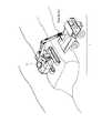
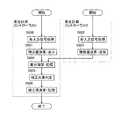
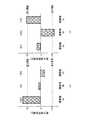
図1は本発明の実施例1に係わる積載補正システム1を構成する積込機と運搬機を示した図である。(Example 1)
<Overall configuration of stacking correction system>
FIG. 1 is a diagram showing a loader and a transporter that constitute a stacking
積載補正システム1は、1台の積込機2と3台の運搬機3a、3b、3cとを有している。実施例1においては、積込機2を油圧ショベルとし、運搬機3a、3b、3cをダンプトラックとしている。 The stacking
空荷の運搬機3aが、積込機2が積込可能な範囲に停止した後、積込機2による積込作業が行われる。積込作業終了後に運搬機3aは発進し、次いで、空荷の運搬機3bが、積込機2が積込可能な範囲に停止し、その後に積込機2による積込作業が行われる。同様の流れによって運搬機3cに対しても積込作業が行われ、鉱山等における掘削積込作業が順次実施される。 After the
なお、運搬機3b及び3cは、運搬機3aと同一の外観であるため、図示を省略する。以下において、運搬機3a〜3cのいずれも選択して説明しない場合には、単に運搬機3とも称する。 The
<積込機>
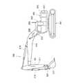
図2は、実施例1における積載補正システム1を構成する積込機2の外観を示す図である。積込機2は、図示しない左走行体及び右走行体を備えた下部車体201と、下部車体201上に旋回可能に取り付けられた上部旋回体202とを有している。また、積込機2の上部旋回体202の前部には、運転室203が取り付けられている。更に、上部旋回体202の前部には、上下揺動自在に作業フロント200が取り付けられ、上部旋回体202の後部には、メインポンプ204及び作動油タンク205が設けられている。そして、運転室203には、他の機器とのデータ転送を可能にするための通信装置206が設けられている。<loader>
FIG. 2 is a diagram illustrating an appearance of the
作業フロント200は、上部旋回体202に対して上下揺動自在に取り付けられたブーム210と、このブーム210に上下揺動自在に取り付けられたアーム211と、このアーム211に上下回動自在に取り付けられたバケット212と、上部旋回体202とブーム210とに連結され、ブーム210を上下方向に揺動させるブームシリンダ213と、ブーム210とアーム211とに連結され、アーム211を上下方向に揺動させるアームシリンダ214と、アーム211とバケット212とに連結され、バケット212を上下方向に回動させるバケットシリンダ215を有している。 The
また、作業フロント200は、その姿勢を検出するために、ブーム210に設けられたブーム傾斜センサ220と、アーム211に設けられたアーム傾斜センサ221と、バケット212に設けられたバケット傾斜センサ222と、を備えている。 Further, the
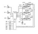
図3は、図2の積込機が備える制御回路を示す回路図である。図3に示した制御回路において、204は図示しないエンジンにより駆動されるメインポンプである。メインポンプ204によって作動油タンク205から吐出した圧油は、コントロール弁230(i)〜(iii)のそれぞれを経て、ブームシリンダ213、アームシリンダ214、及びバケットシリンダ215に対して各々供給される。 FIG. 3 is a circuit diagram showing a control circuit included in the loader of FIG. In the control circuit shown in FIG. 3, 204 is a main pump driven by an engine (not shown). The pressure oil discharged from the
ブーム操作レバー240、アーム操作レバー241、又はバケット操作レバー242を操作することによって発生する各操作信号は、メインコントローラ250に取り込まれる。メインコントローラ250に取り込まれた各操作信号は、コントロール弁230(i)〜(iii)の開閉駆動に使用される。これにより、ブームシリンダ213、アームシリンダ214、及びバケットシリンダ215に対して各々供給される圧油の流量は、各操作レバーの操作量に比例して増減することになる。 Each operation signal generated by operating the
ブームシリンダ213には、ブームボトム圧力センサ260及びブームロッド圧力センサ261が接続されている。ブームボトム圧力センサ260及びブームロッド圧力センサ261の計測信号は、重量計測コントローラ251に入力される。また、重量計測コントローラ251には、表示モニタ270、各傾斜センサ220〜222、通信装置206、及び積込完了スイッチ271が各々接続されている。通信装置206は、後述する運搬機3との情報送受信に使用される。なお、重量計測コントローラ251の動作については後述する。 A boom
次に、シリンダの駆動について説明する。ブームシリンダ213のボトム側油室213(i)へ圧油が供給された場合には、ブーム210は上部旋回体202に対して上方向に揺動駆動され、反対にロッド側油室213(ii)に供給された場合には、ブーム210は上部旋回体202に対して下方向に揺動駆動される。また、アームシリンダ214のボトム側油室214(i)へ圧油が供給された場合には、アーム211はブーム210に対して下方向に揺動駆動され、反対にロッド側油室214(ii)に供給された場合には、アーム211はブーム210に対して上方向に揺動駆動される。更に、バケットシリンダ215のボトム側油室215(i)へ圧油が供給された場合には、バケット212はアーム211に対して下方向に回動駆動され、反対にロッド側油室215(ii)に供給された場合には、バケット212はアーム211に対して上方向に回動駆動される。 Next, driving of the cylinder will be described. When the pressure oil is supplied to the bottom side oil chamber 213(i) of the
<運搬機>
図4は、本実施例における積載補正システム1を構成する運搬機3a、3b、3cの外観を示す図である。運搬機3は、鉱物又は土砂である積載物を積載して走行することが可能である。本実施例に係る運搬機3は、車両本体300と、ベッセル301と、車輪302と、サスペンションシリンダ303と、サスペンション圧力センサ304と、通信装置306と、重量計測コントローラ310とを備えている。<Transportation machine>
FIG. 4 is a diagram showing the external appearance of the
運搬機3の車両本体300には、図示しないエンジン及び走行モータが備えられている。走行モータの動力を車輪302に伝達することで、運搬機3は走行可能となる。ベッセル301は、車両本体300の上部に設置されている。ベッセル301には、積込機2により、土等の作業対象物が積載される。 The vehicle
運搬機3のサスペンションシリンダ303は、車輪302と車両本体300との間に設置されている。車両本体300の重量、ベッセル301の重量、及びベッセル301の積載物の重量の合計に応じた負荷が、サスペンションシリンダ303を介して車輪302に加えられる。サスペンションシリンダ303は、ベッセル301に積載物が積載されると、その重量に応じて縮み、内部に封入された作動油の圧力が高まる。サスペンション圧力センサ304は、作動油の圧力変化を検知するために備えられており、サスペンション圧力センサ304にて生成される検知信号は重量計測コントローラ310に入力される。なお、サスペンション圧力センサ304は、運搬機3の各サスペンションシリンダ303に設置されている。本実施例の運搬機3は4つの車輪302を備えているため、サスペンション圧力センサ304は合計4つとなる。 The
通信装置306は重量計測コントローラ310と接続され、積込機2との情報送受信に使用される。従って、本実施例においては、運搬機3の通信装置306と、積込機2の通信装置206とによって、各種のデータ転送をなす積載補正システム1の通信部が構成されていることになる。なお、重量計測コントローラ310の動作については後述する。 The
<重量計測コントローラの内部構成>
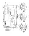
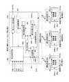
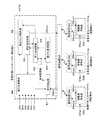
次に、重量計測コントローラ251及び重量計測コントローラ310の内部構成について、図5を参照しつつ説明する。ここで、図5は、実施例1に係る各重量計測コントローラの内部構成を示す概略ステップS図である。<Internal configuration of weight measurement controller>
Next, the internal configurations of the
重量計測コントローラ251には、ブーム傾斜センサ信号220s、アーム傾斜センサ信号221s、バケット傾斜センサ信号222s、ブームボトム圧力センサ信号260s、ブームロッド圧力センサ信号261s、積込完了スイッチ信号271s、及び通信装置206を介した重量計測コントローラ310からの通信信号206s(i)の各信号が入力される。重量計測コントローラ251からの出力信号は、表示モニタ信号270s、及び通信装置206を介した重量計測コントローラ310への通信信号206s(o)である。 The
一方、運搬機3aの重量計測コントローラ310aには、サスペンション圧力センサ信号304as、通信装置306aを介した重量計測コントローラ251からの通信信号306as(i)の各信号が入力される。重量計測コントローラ310aからの出力信号は、通信装置306aを介した重量計測コントローラ251への通信信号306as(o)である。 On the other hand, each signal of the suspension pressure sensor signal 304as and the communication signal 306as(i) from the
なお、運搬機3bの重量計測コントローラ310b及び運搬機3cの重量計測コントローラ310cについては、重量計測コントローラ310aと同様の構成のため、図5において同様の符号を付し、各説明を省略する。また、重量計測コントローラ310a〜310cのいずれも選択して説明しない場合には、単に重量計測コントローラ310とも称する。更に、積載量演算部500a〜500cのいずれも選択して説明しない場合には、単に積載量演算部500とも称する。そして、通信装置306a〜306cのいずれも選択して説明しない場合には、単に通信装置306とも称する。 Since the weight measurement controller 310b of the
各運搬機3の重量計測コントローラ310の内部には、ベッセル301に積載された作業対象物の重量を演算する積載量演算部500が設けられている。すなわち、積載量演算部500が、積込機2から各運搬機3に積み込まれた作業対象物の積載量を計測する積載量計測部に該当する。 Inside the
一方、重量計測コントローラ251の内部は、作業フロント200により運搬される作業対象物の重量を演算する積込量演算部400と、積込量演算部400と重量計測コントローラ310内の積載量演算部500の演算結果の差分を演算する差分演算部401と、差分演算結果を記憶する差分記憶部402と、積込量演算部400及び積載量演算部500a〜500cから演算結果に補正が必要な装置を判定する補正対象判定部403と、補正対象の補正値を演算する補正値演算部404と、補正値を記憶する補正値記憶部405と、表示モニタ信号270sを生成する表示モニタ制御部406とで構成されている。このような重量計測コントローラ251の構成から、積込機2によって積み込まれた作業対象物の積込量を計測する積込量計測部として、積込量演算部400が積込機2に設置されていることになる。 On the other hand, inside the
なお、重量計測コントローラ251及び重量計測コントローラ310は、予め設定した制御周期で一連の入出力を繰り返し実行するよう構成されている。例えば、重量計測コントローラ251においては、積込量演算部400、差分演算部401、補正対象判定部403、補正値演算部404、及び表示モニタ制御部406のそれぞれが既知のCPUから構成され、当該CPUによって各種のプログラムが実行されることによって、各部における処理が実行されるとともに、差分記憶部402及び補正値記憶部405が既知のRAM又はハードディスク等の記憶装置から構成され、各種のデータが当該記憶装置に書き込まれることにより、上述した一連の入出力が繰り返し実行されてもよい。また、重量計測コントローラ251は、上述した一連の入出力が繰り返し実行する1つのプログラム処理を実行するCPUとして構成されていてもよい。 It should be noted that the
<重量計測コントローラの全体処理フロー>
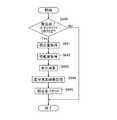
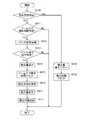
重量計測コントローラ251及び、重量計測コントローラ310の全体処理フローについて図6に示す。図6は、実施例1の重量計測コントローラの全体処理フローに係わるフロー図である。ここで、図6における全体処理フローにおいて、ステップS600、S601、S604〜S606については積込機2の重量計測コントローラ251側にて行われる処理であり、ステップS602及びS603については運搬機3の重量計測コントローラ側にて行われる処理である。<Overall processing flow of the weight measurement controller>
The overall processing flow of the
先ず、ステップS600では、積込機2の重量計測コントローラ251において、前述した各入力信号の取得が行われる。ステップS601では、積込量演算部400による積込量演算及び表示モニタ制御部406による表示モニタ信号270sの生成が行われる。一方、ステップS602では、運搬機3の重量計測コントローラ310において、前述した各入力信号の取得が行われる。ステップS603では、積載量演算部500による積載量演算及び通信装置306を介した積載量演算結果の重量計測コントローラ251への送信が行われる。 First, in step S600, the
次に、ステップS604では、差分演算部401による差分演算及び差分記憶部402への差分演算結果の記憶が行われる。続いて、ステップS605では、補正対象判定部403による補正対象の判定が行われる。その後、ステップS606では、補正値演算部404による補正値演算及び補正値記憶部405への補正値の記憶が行われる。以降、上記各ステップの詳細について説明する。 Next, in step S604, the
≪ステップS601:積込量演算・表示≫
ステップS601の積込量演算・表示について、図7、図8、及び図9を用いて詳述する。図7は、ステップS601のサブルーチンを示している。図8は、本実施例における表示モニタ270の外観を示している。図9は、積込量演算の演算アルゴリズムを説明するための模式図である。<<Step S601: Loading amount calculation/display>>
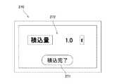
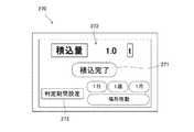
The calculation and display of the loading amount in step S601 will be described in detail with reference to FIGS. 7, 8 and 9. FIG. 7 shows the subroutine of step S601. FIG. 8 shows the appearance of the display monitor 270 in this embodiment. FIG. 9 is a schematic diagram for explaining a calculation algorithm of the load amount calculation.
図7のステップS610では、積込完了スイッチ271のON/OFF判定が行われる。積込完了スイッチ271は、図8に示した表示モニタ270に付設されている。積込完了スイッチ271は、1台の運搬機3への積込作業が完了した際に、積込機2のオペレータにより押下される。積込完了スイッチ271がOFFの場合は、処理がステップS611に移行し、積込完了スイッチ271がONの場合は、処理がステップS618に移行する。 In step S610 of FIG. 7, ON/OFF determination of the
ステップS611では、ブーム上げ操作時間判定が行われる。ブーム210の上部旋回体202に対する上方向への駆動操作が、予め定めた所定値以上連続して行われた場合、処理はステップS612へ移行する。例えば、当該所定値を5秒とした場合、ブーム傾斜センサ信号220sが5秒以上連続してブーム上げ方向へ変動した場合、処理がステップS612へ移行する。なお、当該所定値は積込機2の寸法に応じて適宜変更してもよく、比較的に小さいサイズの積込機に対しては、ブームの移動が速いため、当該所定値を0.5秒としてもよい。 In step S611, a boom raising operation time determination is performed. When the upward driving operation of the
ステップS612では、作業フロント200の動作により掘削されたバケット212内の土量を演算する。すなわち、バケット荷重演算処理が行われる。図9はバケット荷重演算に関る模式図である。バケット荷重Fはブーム回動中心のモーメントMの釣り合い式を解くことで演算される。バケット荷重Fに伴って発生するモーメントMは、荷重点とブーム回動中心の水平距離Lを用いて、M=F・Lで表される。一方、ブームシリンダ213の推力fに伴って発生するモーメントMは、ブーム回動中心までの水平距離lを用いて、M=f・lで表される。水平距離L及びlは、各傾斜センサ220〜222の検出値を用いて容易に演算可能である。また推力fは、ブームボトム圧力センサ260及びブームロッド圧力センサ261の検出値を用いて容易に演算可能である。これらより、未知数であるバケット荷重Fは、F=f・l/Lにより導出される。 In step S612, the amount of soil in the
ステップS613では、バケット傾斜センサ信号222sの監視により、バケット212がアーム211に対して上方向に回動駆動しているか否か判定する。すなわち、バケット放土操作判定が行われる。バケット傾斜センサ信号222sがバケット放土方向へ変動した場合、処理がステップS614に移行する。 In step S613, it is determined by monitoring the bucket
ステップS614では、積込量演算が行われる。具体的には、ステップS612の演算結果であるバケット荷重を現在の積込量に積算する処理が行われる。続いて、ステップS615では、ブーム上げ操作時間をリセットする処理が行われる。 In step S614, the loading amount calculation is performed. Specifically, a process of adding the bucket load, which is the calculation result of step S612, to the current loading amount is performed. Succeedingly, in a step S615, processing for resetting the boom raising operation time is performed.
一般に、積込機2のような作業具がバケットである油圧ショベルは、掘削、ブーム上げ旋回、放土のサイクルを繰り返すことで作業を遂行する。所定時間のブーム上げ操作及びバケット放土操作を検出するステップであるステップS611〜615の処理により、積込量の合計を演算することができる。 Generally, a hydraulic excavator in which a working tool such as the
次いで、ステップS616では、積込量の補正演算が行われる。後述する補正値記憶部405に記憶されている補正値を読込み、ステップS614の演算結果である積込量に加算する処理が行われる。その後、ステップS617では、表示モニタ制御部406による表示モニタ信号270sの生成が行われる。当該処理によって、ステップS616の処理により補正された積込量が、図8の積込量表示部272に表示される。 Next, in step S616, a correction calculation of the loading amount is performed. A process of reading a correction value stored in a correction
一方、ステップS618では、積込量表示部272の表示値をゼロリセットする積込量表示リセット処理が行われる。 On the other hand, in step S618, a loading amount display reset process of resetting the display value of the loading
上記ステップS617又はステップS618による処理が行われることで、ステップS601の積込量演算・表示に係る処理が終了することになる。ここで、上述した各種の判定、演算、及びリセットに関する処理は、重量計測コントローラ251の積込量演算部400に当該処理に関する各種のデータが入力されるため、積込量演算部400によって実行されることになる。 By performing the processing in step S617 or step S618, the processing relating to the load amount calculation/display in step S601 ends. Here, the various processes related to the determination, calculation, and reset described above are executed by the loading
≪ステップS603:積載量演算・送信≫
ステップS603の積載量演算・送信について、図10、図11を用いて詳述する。図10は、ステップS603のサブルーチンを示している。図11は、積載量演算の演算アルゴリズムを説明するためのサスペンション圧力平均値と積載量との関係を示すグラフである。<<Step S603: Loaded amount calculation/transmission>>
The load amount calculation/transmission in step S603 will be described in detail with reference to FIGS. FIG. 10 shows the subroutine of step S603. FIG. 11 is a graph showing the relationship between the suspension pressure average value and the load amount for explaining the calculation algorithm of the load amount calculation.
図10のステップS630では、積載量演算が行われる。具体的には、サスペンション圧力センサ304の検出値から積載量を換算して算出する。ここで、サスペンション圧力と積載量の対応関係は、図11に示した通り、重量計測コントローラ310において予め定められている。前述の通り、本実施例の運搬機3は4つの車輪302を備えており、サスペンション圧力センサ304は1台の運搬機において合計4個である。図11の横軸はサスペンション圧力センサ304の検出値の平均値(MPa)を示し、縦軸は積算量(t)を示している。 In step S630 of FIG. 10, a load amount calculation is performed. Specifically, it is calculated by converting the loading amount from the detection value of the
次に、ステップS631では、積載量の補正演算が行われる。通信装置306を介して、後述する補正値記憶部405に記憶されている補正値を読込み、ステップS630の演算結果である積載量に加算する処理が行われる。なお、積載量演算に関するステップS630及び補正演算に関するステップS631は、重量計測コントローラ310の積載量演算部500に当該処理に関する各種のデータが入力されるため、積載量演算部500によって実行されることになる。 Next, in step S631, a correction calculation of the load amount is performed. A process of reading a correction value stored in a correction
次に、ステップS632では、ステップS631の演算結果を、通信装置306を介して重量計測コントローラ251へ送信する処理が行われる。当該ステップS632による積算量の送信の処理が行われることで、ステップS603の積算量演算・送信に係る処理が終了することになる。 Next, in step S632, a process of transmitting the calculation result of step S631 to the
≪ステップS604:差分演算・記憶≫
ステップS604の差分演算・記憶について、図12、図13を用いて詳述する。図12は、ステップS604のサブルーチンを示している。図13は、差分演算結果の記憶に関する模式図である。<<Step S604: Difference Calculation/Memory>>
The difference calculation/storage in step S604 will be described in detail with reference to FIGS. FIG. 12 shows the subroutine of step S604. FIG. 13 is a schematic diagram regarding storage of the difference calculation result.
図12のステップS640では、積込完了スイッチ271のON/OFF判定が行われる。ステップS640の処理は、ステップS610の処理と同一であるため、説明を省略する。積込完了スイッチ271がONの場合は、処理がステップS641に移行する。一方で、積込完了スイッチ271がOFFの場合は、ステップS604の差分演算・記憶に係る処理が終了することになる。 In step S640 of FIG. 12, ON/OFF determination of the
ステップS641では、図7のステップS616の演算結果である、補正後の積込量情報が取得される。具体的には、積込量演算部400から差分演算部401へ当該補正後の積込量情報が直接入力されることになる。次いでステップS642では、図10のステップS632の処理結果である、補正後の積載量情報が取得される。具体的には、通信装置206及び通信装置306によるデータ転送が行われ、積載量演算部500によって演算された補正後の積載量情報が、差分演算部401に入力されることになる。 In step S641, the corrected loading amount information, which is the calculation result of step S616 in FIG. 7, is acquired. Specifically, the corrected load amount information is directly input from the load
ステップS643では、差分演算部401において、ステップS641で取得した積込量とステップS642で取得した積載量の差分演算が行われる。具体的には、積込機2の積込量をW、運搬機3aの積載量をWaとると、差分は(W−Wa)で求められる。他の運搬機に関する差分演算処理も同様に、運搬機3bの積載量をWbとすると、上記差分は(W−Wb)で求められ、運搬機3cの積載量をWcとすると、上記差分は(W−Wc)で求められる。 In step S643, the
ステップS644では、差分記憶部402への差分演算結果の記憶処理が行われる。図13に示されるように、運搬機毎の差分演算結果が、各々差分記憶部402に記憶される。図13においては、記憶される差分演算結果の一例が示されており、運搬機3a及び運搬機3cに係る差分演算結果は正の値であり、運搬機3bに係る差分演算結果は負の値となっている。すなわち、運搬機3a及び運搬機3cのそれぞれにおいて算出された補正後の積載量(Wa、Wc)は、積込機2において算出された各運搬機に対する補正後の各積込量(W)よりも少ない結果となっている。一方、運搬機3bにおいて算出された補正後の積載量(Wb)は、積込機2において算出された運搬機3bに対する補正後の積込量(W)よりも多い結果となっている。 In step S644, the
ステップS645では、図7のステップS614の演算結果である積込量をゼロリセットする、積込量リセット処理が行われる。当該ステップS645による積込量リセット処理が行われることで、ステップS604の差分演算・記憶に係る処理が終了することになる。 In step S645, a loading amount reset process of resetting the loading amount, which is the calculation result of step S614 of FIG. 7, to zero is performed. By performing the loading amount reset process in step S645, the process related to the difference calculation/storage in step S604 ends.
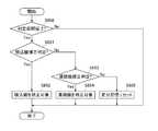
≪ステップS605:補正対象判定≫
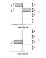
ステップS605の補正対象判定について、図14、図15、及び図16を用いて詳述する。図14は、ステップS605のサブルーチンを示している。図15は、積込機の補正判定に関する模式図である。図16は、運搬機の補正判定に関する模式図である。<<Step S605: Determination of Correction Target>>
The correction target determination in step S605 will be described in detail with reference to FIGS. 14, 15, and 16. FIG. 14 shows the subroutine of step S605. FIG. 15: is a schematic diagram regarding correction determination of a loader. FIG. 16 is a schematic diagram regarding correction determination of a transport machine.
図14のステップS650では、全運搬機の差分演算が完了したか否かの判定が行われる。積込機2による運搬機3aへの積込作業が完了すると、図12のフローに従いステップS644の処理が行われ、差分演算結果(W−Wa)が差分記憶部402に記憶される。次いで、積込機2による運搬機3bへの積込作業が完了すると、同様に差分演算結果(W−Wb)が差分記憶部402に記憶される。さらに、積込機2による運搬機3cへの積込作業が完了すると、同様に差分演算結果(W−Wc)が差分記憶部402に記憶される。本実施例では、差分記憶部402を参照し、運搬機3cの差分演算結果が記憶された際に、全運搬機の差分演算が完了したとみなす判定が行われる。なお、補正対象判定部403が差分記憶部402に記憶されたデータを参照することから、本判定処理は補正対象判定部403によって実行されることになる In step S650 of FIG. 14, it is determined whether the difference calculation of all the transporting machines is completed. When the loading operation of the
ステップS650の判定が肯定された場合は、処理がステップS651へ移行する。一方、全運搬機の差分演算が完了していないと判定、すなわちステップS650の判定が否定された場合は、ステップS605の補正対象判定に係る処理が終了することになる。 If the determination in step S650 is affirmative, the process proceeds to step S651. On the other hand, if it is determined that the difference calculation of all the transporting machines has not been completed, that is, if the determination in step S650 is negative, the process relating to the correction target determination in step S605 ends.
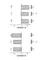
ステップS651では、積込機補正判定が行われる。補正対象判定部403では、図15に示されるように、差分演算結果に対する閾値(差分閾値)が予め設定されている。すなわち、本実施例においては、補正対象判定部403が、差分記憶部402に記憶される差分演算結果に対する閾値を設定可能な閾値設定部としても機能している。本実施例では、差分閾値を便宜上10[t]とする。図15a及び図15bに示されるように、全運搬機(運搬機3a〜3c)の差分演算結果が、同一方向の差分閾値を上回っている場合は、処理がステップS652へ移行し、積込機2の積込量演算部400を補正対象とする判定が行われる。なお、図15aでは全運搬機の差分演算結果がプラス側の差分閾値を超えている場合を例示し、図15bでは全運搬機の差分演算結果がマイナス側の差分閾値を超えている場合を例示している。 In step S651, loader correction determination is performed. In the correction
ステップS653では、運搬機補正判定が行われる。図16(a)及び図16(b)に示されるように、何れか1台以上の運搬機の差分演算結果が差分閾値を上回っている場合(但し、全運搬機の差分演算結果が、同一方向の差分閾値を上回っている場合は含まない)は、処理がステップS654へ移行し、運搬機を補正対象とする判定が行われる。具体的には、図16(a)の場合には、運搬機3aの積載量演算部500aを補正対象とする判定が行われる。図16(b)の場合には、運搬機3bの積載量演算部500b及び、運搬機3cの積載量演算部500cを補正対象とする判定が行われる。 In step S653, a transporter correction determination is performed. As shown in FIGS. 16(a) and 16(b), when the difference calculation result of any one or more carriers exceeds the difference threshold value (however, the difference calculation results of all the carriers are the same. If it exceeds the difference threshold of the direction), the process proceeds to step S654, and it is determined that the transport machine is the correction target. Specifically, in the case of FIG. 16A, it is determined that the loading
ステップS655では、差分記憶部402に記憶されている差分演算結果をリセット(クリア)する、差分記憶リセット処理が行われる。全運搬機の差分演算が完了した状況において、補正対象が選択されなかった(補正が不要と判定された)場合、差分記憶部402に記憶されている差分演算結果がリセットされる。 In step S655, a difference storage reset process of resetting (clearing) the difference calculation result stored in the
上述したステップS652、ステップS654、又はステップS655による処理が終了することにより、ステップS605の補正対象判定に係る処理が終了することになる。 When the process in step S652, step S654, or step S655 described above ends, the process related to the correction target determination in step S605 ends.
≪ステップS606:補正値演算・記憶≫
ステップS606の補正値演算・記憶について、図17〜図20を用いて詳述する。図17は、ステップS606のサブルーチンを示している。図18は、積込機の補正演算に関する模式図である。図19は、運搬機の補正演算に関する模式図である。図20は、補正値の積算・記憶に関する模式図である。<<Step S606: Correction Value Calculation/Memory>>
The calculation and storage of the correction value in step S606 will be described in detail with reference to FIGS. FIG. 17 shows the subroutine of step S606. FIG. 18 is a schematic diagram regarding the correction calculation of the loader. FIG. 19 is a schematic diagram regarding the correction calculation of the transport machine. FIG. 20 is a schematic diagram regarding integration/storage of correction values.
図17のステップS660では、図14のステップS652を通過したかの判定が行われる。ステップS652を通過し、積込機2の積込量演算部400を補正対象とする判定が行われた場合は、処理がステップS661へ移行する。 In step S660 of FIG. 17, it is determined whether step S652 of FIG. 14 has been passed. If the determination is made that the loading
ステップS661では、補正値演算部404による積込機補正値の演算が行われる。図18(a)は、図15(a)に示した差分演算結果が得られた際の、積込機の補正値演算結果を表している。本実施例における積込機補正値W’は、全運搬機(運搬機3a〜3c)の差分演算結果の平均値を用いて算出している。図15(a)より、(W−Wa)=11[t]、(W−Wb)=11[t]、(W−Wc)=14[t]であるため、積込機補正値W’は、W’=−12[t]と演算される。図18(b)は、図15(b)に示した差分演算結果が得られた際の、積込機の補正値演算結果を表している。同様の演算により、積込機補正値W’は、W’=12[t]と演算される。 In step S661, the loader correction value is calculated by the correction
ステップS662では、図14のステップS654を通過したかの判定が行われる。ステップS654を通過し、運搬機3の積載量演算部500を補正対象とする判定が行われた場合は、処理がステップS663へ移行する。 In step S662, it is determined whether or not step S654 in FIG. 14 has been passed. If the determination is made that the load amount calculation unit 500 of the
ステップS663では、補正値演算部404による運搬機補正値の演算が行われる。図19(a)は、図16(a)に示した差分演算結果が得られた際の、運搬機の補正値演算結果を表している。本実施例における運搬機補正値Wa’〜Wc’は、当該運搬機の差分演算結果と同値としている。図16(a)より、(W−Wa)=14[t]であるため、運搬機補正値Wa’は、Wa’=14[t]となる。図19(b)は、図16(b)に示した差分演算結果が得られた際の、運搬機の補正値演算結果を表している。同様の演算により、運搬機補正値Wb’は、Wb’=−12[t]、運搬機補正値Wc’は、Wc’=11[t]と演算される。 In step S663, the correction
ステップS664では、ステップS661又はステップS663により新たに演算された補正値を、補正値記憶部405に記憶されている従前の補正値に対して積算する処理が行われる。図20は補正値積算のイメージの一例を示している。ここで、図20に示されるイメージを構成する積込機2及び運搬機3の各種データは、図15、図16、図18、及び図19に示されているイメージを構成する積込機2及び運搬機3の各種データとは関連しておらず、図20は図15、図16、図18、及び図19とは異なる場合のイメージを示している。 In step S664, a process of integrating the correction value newly calculated in step S661 or step S663 with the previous correction value stored in the correction
ステップS665では、ステップS664の演算結果である補正値積算結果を、補正値記憶部405に記憶する処理が行われる。 In step S665, a process of storing the correction value integration result, which is the calculation result of step S664, in the correction
ステップS666では、差分記憶部402に記憶されている差分演算結果をリセット(クリア)する、差分記憶リセット処理が行われる。処理の内容は、図14のステップS655と同一である。 In step S666, a difference storage reset process of resetting (clearing) the difference calculation result stored in the
<実施例1の効果>
上記のように構成され動作する積載補正システム1によれば、積込機2に設置される積込量演算部400と運搬機3に設置される積載量演算部500の計測値を相互監視して補正することが可能となる。経年劣化などにより計測装置の計測値そのものに誤差が発生した場合でも、運搬機3の制限積載量に対する過不足のない積込が容易となり、作業効率の向上が期待できる。<Effect of Example 1>
According to the
また、本実施例では、差分記憶部402に記憶される全ての差分演算結果が所定の閾値を上回った場合、積込機2による積込量計測に誤差が発生しているとみなす判定が行われる。加えて、差分記憶部402に記憶される何れか1つ以上の差分演算結果が所定の閾値を上回った場合(但し、全運搬機の差分演算結果が、同一方向の差分閾値を上回っている場合を含まない)、当該する運搬機3による積載量計測に誤差が発生しているとみなす判定が行われる。これらの補正対象判定により、誤差の発生対象を容易に特定することが可能となる。 In addition, in this embodiment, when all the difference calculation results stored in the
更に、本実施例では、差分演算部401と、差分記憶部402と、補正対象判定部403と、補正値演算部404と、表示モニタ270とが、各々積込機2に設置されている。このため、積込機2以外の場所に各構成要素を設置するよりも、システム構成が簡易化され、低コスト化が可能となる。 Further, in the present embodiment, the
(実施例2)
実施例1に係る積載補正システム1とは異なり、判定期間を設定することができる積載補正システムを実施例2として以下に説明する。なお、以下に記述する内容以外については、前述の実施例1と同様である。(Example 2)
Unlike the stacking
<積込機:制御回路の全体構成>
実施例2に係る積込機2が備える制御回路を図21に示す。図3に示す実施例1に係る制御回路との相違は、判定期間設定スイッチ273が重量計測コントローラ251に接続されている点である。<Loader: Overall control circuit configuration>
FIG. 21 shows a control circuit included in the
<重量計測コントローラの内部構成>
実施例2に係る重量計測コントローラ251及び重量計測コントローラ310の内部構成について図22に示す。図5に示す実施例1に係る各コントローラとの相違は、重量計測コントローラ251内に、判定を行うための期間を設定可能な判定期間設定部407が追加された点である。<Internal configuration of weight measurement controller>
FIG. 22 shows the internal configuration of the
判定期間設定スイッチ273は、図23に示した表示モニタ270に付設されており、積込機2のオペレータにより、「1日」「1週」「1月」「場所移動」の何れか1つが設定される。判定期間設定部407には、判定期間設定スイッチ信号273sが入力される。 The determination
≪ステップS604:差分演算・記憶≫
実施例2に係るステップS604の差分演算・記憶について、図24を用いて詳述する。図24は、ステップS604のサブルーチンを示している。図12との相違は、ステップS646が新たに追加された点である。<<Step S604: Difference Calculation/Memory>>
The difference calculation/storage in step S604 according to the second embodiment will be described in detail with reference to FIG. FIG. 24 shows the subroutine of step S604. The difference from FIG. 12 is that step S646 is newly added.
ステップS646では、ステップS643の差分演算結果と、差分記憶部402に記憶されている従前の差分演算結果を用いて、差分演算結果の平均値を算出する処理が差分演算部401によって行われる。 In step S646, the
ステップS644では、ステップS646で算出された差分演算結果の平均値を差分記憶部402へ記憶する処理が行われる。 In step S644, a process of storing the average value of the difference calculation results calculated in step S646 in the
≪ステップS605:補正対象判定≫
実施例2に係るステップS605の補正対象判定について、図25を用いて詳述する。図25は、ステップS605のサブルーチンを示している。図14との相違は、ステップS650がステップS656に置換された点である。<<Step S605: Determination of Correction Target>>
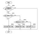
The correction target determination in step S605 according to the second embodiment will be described in detail with reference to FIG. FIG. 25 shows the subroutine of step S605. The difference from FIG. 14 is that step S650 is replaced with step S656.
ステップS656では、判定期間設定部407の設定状態に従って、判定期間が完了したか否かの判定が行われる。判定期間設定スイッチ273の設定状態が、「1日」「1週」「1月」の場合は、重量計測コントローラ251内の図示しない時間計測装置により、当該スイッチが設定されてからの経過時間が計測される。経過時間がスイッチの設定を上回った場合、判定期間完了とみなして、処理がステップS651へ移行し、その後においては実施例1と同様の処理が行われる。 In step S656, it is determined whether or not the determination period is completed according to the setting state of the determination
一方、判定期間設定スイッチ273の設定状態が、「場所移動」の場合は、重量計測コントローラ251に接続されている図示しないGPSを用いて、積込機2の作業場所が判定される。積込機2が予め設定された作業場所から別の作業場所へ移動した場合、判定期間完了とみなして、処理がステップS651へ移行し、その後においては実施例1と同様の処理が行われる。 On the other hand, when the setting state of the determination
なお、上記判定期間が完了したか否かの判定に関する処理(ステップS656)は、判定期間設定スイッチ信号273sが判定期間設定部407に入力されることから、判定期間設定部407によって実行されることになる。 It should be noted that the process relating to the determination of whether or not the determination period is completed (step S656) is executed by the determination
<実施例2の効果>
上記のように構成され動作する実施例2に係る積載補正システム1によれば、ユーザが予め設定した期間内の差分記憶情報を用いて補正対象判定及び補正値演算が行われることになる。積載補正システムの使用方法や使用環境に合わせた適切な補正値演算が可能となることから、実施例1の効果に加えて、さらなる作業効率向上、ユーザビリティ向上が期待できる。<Effect of Example 2>
According to the stacking
(実施例3)
実施例1に係る積載補正システム1とは異なり、補正値に関する表示を行うことができる積載補正システムを実施例3として以下に説明する。なお、以下に記述する内容以外については、前述の実施例1と同様である。(Example 3)
Unlike the stacking
<重量計測コントローラの内部構成>
実施例3に係る重量計測コントローラ251及び、重量計測コントローラ310の内部構成について図26に示す。図5に示す実施例1に係る各コントローラとの相違は、表示モニタ制御部406に補正値演算部404が接続されている点である。すなわち、実施例3においては、補正値に関するデータが表示モニタ制御部406を介して表示モニタ270に入力され、表示モニタ270に当該補正値に関する情報が表示されることになる。<Internal configuration of weight measurement controller>
FIG. 26 shows the internal configurations of the
図27に、本実施例における表示モニタ270の外観を示す。表示モニタ制御部406を介した補正対象及び補正値の情報が、図27の補正対象・補正値表示部274に表示される。図27に示すように、補正対象・補正値表示部274には、補正対象として積込機2及び3台の運搬機3が表示され、各補正対象の補正値・演算結果、従前の補正値、及び補正値・積算結果が表示されている。すなわち、本実施例においては、従前の補正値、直前に行われた補正値演算、及び新しい補正値が表示されることになる。 FIG. 27 shows an appearance of the display monitor 270 in this embodiment. Information on the correction target and the correction value via the display
≪ステップS606:補正値演算・記憶≫
実施例3に係るステップS606の補正値演算・記憶について、図28を用いて詳述する。図28は、ステップS606のサブルーチンを示している。図17との相違は、ステップS667が新たに追加された点である。<<Step S606: Correction Value Calculation/Memory>>
The correction value calculation/storage in step S606 according to the third embodiment will be described in detail with reference to FIG. FIG. 28 shows the subroutine of step S606. The difference from FIG. 17 is that step S667 is newly added.
ステップS667では、ステップS661またはステップS663により新たに演算された補正値演算結果、補正値記憶部405に記憶されている従前の補正値、ステップS664において演算された補正値積算結果の各々を、図27の補正対象・補正値表示部274に表示する処理が行われる。 In step S667, the correction value calculation result newly calculated in step S661 or step S663, the previous correction value stored in the correction
<実施例3の効果>
上記のように構成され動作する実施例3に係る積載補正システム1によれば、積込機2のオペレータや積載補正システムの管理者が、現在の補正値情報を把握することが可能となる。積込量演算部400や積載量演算部500の再校正実施可否を判断することが可能となるなど、実施例1の効果に加えて、ユーザビリティの向上が期待できる。<Effect of Example 3>
According to the stacking
(実施例4)
実施例3に係る積載補正システム1とは異なり、補正を実施するか否かをオペレータが決定できる積載補正システムを実施例4として以下に説明する。なお、以下に記述する内容以外については、前述の実施例1及び実施例3と同様である。(Example 4)
Unlike the stacking
<積込機:制御回路の全体構成>
実施例4に係る積込機2が備える制御回路を図29に示す。図3に示す実施例1に係る制御回路との相違は、補正実施判定スイッチ275が重量計測コントローラ251に接続されている点である。<Loader: Overall control circuit configuration>
FIG. 29 shows a control circuit included in the
<重量計測コントローラの内部構成>
実施例4に係る重量計測コントローラ251及び重量計測コントローラ310の内部構成について図30に示す。図26に示す実施例3に係る各コントローラとの相違は、補正値演算部404に補正実施判定スイッチ信号275sが入力されている点である。<Internal configuration of weight measurement controller>
FIG. 30 shows the internal configuration of the
補正実施判定スイッチ275は、図31に示した表示モニタ270に付設されており、積込機2のオペレータの押下を受け付ける。すなわち、積込機2のオペレータは、図31に示す「許可」又は「不許可」のいずれかを選択して押下することにより、新たな補正を行うか否かを選択することができる。 The correction
≪ステップS606:補正値演算・記憶≫
実施例4に係るステップS606の補正値演算・記憶について、図32を用いて詳述する。図32は、ステップS606のサブルーチンを示している。図28との相違は、ステップS668が新たに追加された点である。<<Step S606: Correction Value Calculation/Memory>>
The correction value calculation/storage in step S606 according to the fourth embodiment will be described in detail with reference to FIG. FIG. 32 shows the subroutine of step S606. The difference from FIG. 28 is that step S668 is newly added.
ステップS668では、ステップS667の処理により図31の補正対象・補正値表示部274に表示された表示値を、補正値記憶部405に記憶するか否かの判定が、補正値演算部404によって行われる。すなわち、本実施例においては、補正値演算部404が補正実施判定部としても機能する。 In step S668, the correction
具体的には、積込機2のオペレータにより、補正実施判定スイッチ275の「許可」が押下された場合は、補正値演算部404が補正を行うことと判定し、フローの処理がステップS665へ移行して新たな補正値が補正値記憶部405に記憶される。一方、補正実施判定スイッチ275の「不許可」が押下された場合は、補正値演算部404が補正を行わないことと判定し、フローの処理がステップS666へ移行することになり、新たな補正値が補正値記憶部405に記録されることがなく、差分記憶がリセットされる。 Specifically, when the operator of the
<実施例4の効果>
上記のように構成され動作する実施例4に係る積載補正システム1によれば、積込機2のオペレータや積載補正システム1の管理者が、新たに演算された補正値の採否について意思決定することが可能となる。意図しない補正を防止することが可能となることから、実施例1の効果に加えて、ユーザビリティの向上が見込める。<Effect of Example 4>
According to the stacking
(実施例5)
実施例3に係る積載補正システム1とは異なり、補正を実施するか否かをオペレータが決定できる積載補正システムを実施例5として以下に説明する。なお、以下に記述する内容以外については、前述の実施例1及び実施例3と同様である。(Example 5)
Unlike the stacking
<重量計測コントローラの内部構成>
実施例5に係る重量計測コントローラ251及び重量計測コントローラ310の内部構成について図33に示す。図26に示す実施例3に係る各コントローラとの相違は、重量計測コントローラ251内に再校正判定部408が追加された点である。また、再校正判定部408は表示モニタ制御部406と接続している。このため、実施例5においては、再校正の判定結果に関する情報も表示モニタ制御部406を介して表示モニタ270に入力され、表示モニタ270に当該再校正判定結果が表示されることになる。<Internal configuration of weight measurement controller>
FIG. 33 shows the internal configuration of the
図34に、本実施例における表示モニタ270の外観を示す。表示モニタ制御部406を介した再校正判定部408の判定結果が、再校正判定結果表示部276に表示される。図34に示す一例においては、各補正対象に対して再校正の必要性が表示されることになり、積込機2のオペレータが再校正の要否を容易に把握することができるようになっている。 FIG. 34 shows the appearance of the display monitor 270 in this embodiment. The determination result of the
<重量計測コントローラの全体処理フロー>
実施例5に係る重量計測コントローラ251及び重量計測コントローラ310の全体処理フローについて図35に示す。図6に示す実施例1との相違は、ステップS607が新たに追加された点である。<Overall processing flow of the weight measurement controller>
FIG. 35 shows the overall processing flow of the
ステップS607では、再校正判定部408による再校正判定及び、表示モニタ制御部406を介した表示モニタ270への表示処理が行われる。 In step S607, recalibration determination by the
再校正判定部408には、補正値記憶部405に記憶されている補正値に対して、要再校正と判定する再校正判定閾値が予め設定されている。本実施例では、プラス側の再校正判定閾値を30[t]、マイナス側の再校正判定閾値を−30[t]と設定している。補正値記憶部405に記憶されている補正値が再校正判定閾値を超えた場合(すなわち、補正値が30より大きい場合又は−30より小さい場合)、再校正判定結果表示部276に、要再校正である旨が表示される。本実施例では、補正対象・補正値表示部274に表示された補正値積算結果が−32[t]となった積込機2が、要再校正(「●」)と判定されている。 The
<実施例5の効果>
上記のように構成され動作する実施例5に係る積載補正システム1によれば、積込量演算部400または積載量演算部500に対する補正値の範囲を予め設定し、補正値が範囲外となった場合に、積込機2のオペレータや積載補正システム1の管理者に報知することが可能となる。このため、再校正(メンテナンス)すべきタイミングを容易に把握することが可能となることから、実施例1の効果に加えて、ユーザビリティの向上が見込める。<Effect of Example 5>
According to the stacking
(変形例)
本発明は上記の各実施例に限定されない。以下において、各種の変形例の構成及び処理フロー等を説明する。(Modification)
The present invention is not limited to the above embodiments. The configurations and processing flows of various modifications will be described below.
上述した各実施例では、積込機2の重量計測コントローラ251にて補正対象の判定、補正値の演算等を行うために、例えば図5に示すように、差分演算部401、差分記憶部402、補正対象判定部403、補正値演算部404、及び補正値記憶部405を重量計測コントローラ251の内部に設けていたが、このような構成に限定されない。例えば、補正対象の判定、補正値の演算等を行うための各構成要素を、積込機2の車外に設置することも可能である。例えば、図36に示したように、積載補正システム管理コントローラ700及び通信装置701を備える外部の中央管理装置(管理センター)を新たに設けることができる。 In each of the above-described embodiments, the
具体的に、上記変形例に係る積載量補正システムにおいては、当該中央管理装置の積載補正システム管理コントローラ700の内部に、差分演算部401、差分記憶部402、補正対象判定部403、補正値演算部404、及び補正値記憶部405が設けられている。また、上記変形例に係る積載量補正システムにおいては、積込機2と運搬機3とが各種の情報を互いに送受信するのではなく、通信装置206と通信装置701と又は通信装置306と通信装置701とによる通信接続により、積込機2の積込量の情報及び運搬機3の積載量の情報等が通信信号701s(i)として積載補正システム管理コントローラ700に入力される。更に、積載補正システム管理コントローラ700において算出された補正値等の情報が通信信号701s(o)として、通信装置701を介して積込機2又は運搬機3のそれぞれに向けて出力される。 Specifically, in the load amount correction system according to the above modification, the
なお、上記変形例に係る積載量補正システムにおいては、通信装置206、通信装置306、及び通信装置701から各種のデータ転送をなす通信部が構成されることになる。 In addition, in the load amount correction system according to the above modification, the
また、上述した実施例1においては、図7及ぶ図8に示すように、積込機2の積込作業の完了を、積込完了スイッチ271を用いて指示する構成としたがその限りではない。例えば、積込機2による運搬機3への積込回数を予め設定し、設定された積込回数に到達したか否かによって、積込機2の積込作業が完了しなか否かの判断を行っても良い。 Further, in the above-described first embodiment, as shown in FIG. 7 and FIG. 8, the loading operation of the
具体的には、図7のステップS610に代えて、図37のステップS710においては、予め設定された積込回数に到達したか否かの積込回数判定が行われる。また、積込量演算の回数は、ステップS617の積込量表示の処理が完了後に、ステップS711の処理として記憶(カウント)されることになる。更に、予め設定された積込回数に到達し、積込機2の積込作業が完了した判断された場合(ステップS710のYes)、ステップS618の積込量表示リセットの処理後に、ステップS711の処理として積込回数がリセットされることになる。 Specifically, instead of step S610 of FIG. 7, in step S710 of FIG. 37, the number of times of loading is determined whether or not the preset number of times of loading has been reached. Further, the number of times of loading amount calculation is stored (counted) as the process of step S711 after the loading amount display process of step S617 is completed. Further, when the preset number of times of loading is reached and it is determined that the loading operation of the
図37に係る変形例の構成によれば、積込完了スイッチ押下が省略できるため、積込機オペレータの作業負担が軽減する効果が得られる。 According to the configuration of the modified example of FIG. 37, since the pressing of the loading completion switch can be omitted, the work load on the operator of the loader can be reduced.
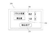
更に、上述した実施例1では、積込機2から運搬機3への積込量に対して補正演算を行っていたが、積込機2のバケット荷重に対して補正演算を行ってもよい。このような場合には、図8に示す実施例1の表示モニタ270の外観とは異なり、例えば、図38に示したように、バケット荷重表示部720を追加することが可能である。 Further, in the above-described first embodiment, the correction calculation is performed on the loading amount from the
このような変形例の場合の積込量演算・表示のフローを図39に示す。実施例1における図7との相違は、ステップS616の積込量補正演算がステップS721のバケット荷重補正演算に置換された点、ステップS722のバケット荷重表示、ステップS723のバケット表示荷重リセットが新たに追加された点である。なお、積込量補正演算のバケット荷重補正演算への置換については、例えば、補正値記憶部405に記憶されている補正値を、積込機による運搬機への積込回数で除す方法が考えられる。 FIG. 39 shows a flow of load amount calculation/display in the case of such a modified example. The difference from FIG. 7 in the first embodiment is that the loading amount correction calculation in step S616 is replaced by the bucket load correction calculation in step S721, the bucket load display in step S722, and the bucket display load reset in step S723 are newly added. This is an added point. Regarding replacement of the loading amount correction calculation with the bucket load correction calculation, for example, a method of dividing the correction value stored in the correction
図38に係る変形例の構成によれば、積込機2のバケットに積み込まれている鉱物又は土砂等のバケット荷重が表示されるため、積込機のオペレータが、運搬機3への積込後の積込量を事前に把握することが容易となる。運搬機3の目標積載量を実現し易くなることから、さらなる作業効率の向上が期待できる。 According to the configuration of the modified example of FIG. 38, the bucket load of minerals, earth and sand, etc. loaded in the bucket of the
上述した実施例においては、補正対象の判定について、差分閾値を用いる方法として、図14、図15、及び図16を参照して説明したが、補正対象判定の方法はこの限りではない。例えば、補正対象の判定は、図40及び図41に示しめすように、差分閾値を用いない判定も可能である。 In the above-described embodiment, the method of determining the correction target has been described with reference to FIGS. 14, 15, and 16 as the method of using the difference threshold, but the method of determining the correction target is not limited to this. For example, the determination of the correction target may be a determination without using the difference threshold, as shown in FIGS. 40 and 41.
このような差分閾値を用いない判定においては、全運搬機3(運搬機3a〜3c)の差分演算結果の符号が同一である場合、積込機2の積込量演算部400が補正対象となる判定が行われる。すなわち、図40(a)に示すような、積込機2における演算結果よりも、全運搬機3における演算結果が小さくなる場合、又は図40(b)に示すような、積込機2における演算結果よりも、全運搬機3における演算結果が大きくなる場合には、積込機2の積込量演算部400のみが補正対象となる。 In the determination not using such a difference threshold, when the signs of the difference calculation results of all the transporters 3 (
また、運搬機補正判定についても差分閾値を用いずに、差分演算結果の絶対値が最大の運搬機3を補正対象とすれば良い。具体的には、図41(a)の場合には、運搬機3aの差分演算結果の絶対値が「14(t)」で最大であるため、運搬機3aの積載量演算部500aを補正対象とする判定が行われる。また、図41(b)の場合には、運搬機3bの差分演算結果の絶対値が「12(t)」で最大であるため、運搬機3bの積載量演算部500bを補正対象とする判定が行われる。 Also, regarding the transport machine correction determination, the
上述した実施例では積込機2を図2の構成としたがその限りではない。例えば、作業フロントの関節数など、運搬機3への積込が可能な任意の構成が適用できる。また、積込機2の制御回路を図3の構成としたがその限りではない。例えば、メインコントローラ250に重量計測コントローラ251の役割を兼ねさせることも可能である。更に、運搬機3を図4の構成としたがその限りではない。積込機2による積込作業が可能であれば良く、例えば、車輪の個数を4個としたが、当然6個にするなどの構成も適用できる。 Although the
上述した実施例1においては、積込量演算の一例を図7のフローの一部として説明したが、その限りではない。すなわち、積込機2の積込量が演算可能なあらゆる手段が該当する。例えば、ブーム上げ操作時間をバケット荷重演算のトリガーとしたが、上部旋回体202の下部車体201に対する旋回動作に置換しても良い。バケット放土操作判定にバケット傾斜センサ信号を用いたが、当然、バケット操作レバー242の操作信号を用いても良い。 In the above-described first embodiment, an example of the loading amount calculation has been described as a part of the flow of FIG. 7, but it is not limited to that. That is, any means capable of calculating the loading amount of the
上述した実施例1においては、積載量演算の一例を図11を参照して説明したが、その限りではない。すなわち、ベッセル301に積載された対象物の重量が計測可能なあらゆる手段が該当する。また、上述した本実施例では運搬機の台数を3台としたが、当然ながらその限りではない。複数台であれば任意の台数に適用可能である。なお、本発明が想定される掘削現場としては3台から5台の運搬機が使用されることが多い。更に、上述した各実施例においては、積込機2を油圧ショベルとし、運搬機3をダンプトラックとしているが、これに限定されることはない。例えば、運搬機3をホイールローダとしてもよい。 In the above-described first embodiment, an example of the load amount calculation has been described with reference to FIG. 11, but it is not limited thereto. That is, any means capable of measuring the weight of the object loaded on the
上述した各実施例における補正値演算方法は一例であり、上述した記載内容に当該補正値演算方法が限定されない。例えば、差分演算結果に所定の係数(ゲイン)を掛ける構成がありえる。当該構成によれば、積込量計測結果及び積載量計測結果の急激な変化が防止され、ユーザに与える違和感を緩和できる。 The correction value calculation method in each of the above-described embodiments is an example, and the correction value calculation method is not limited to the above description. For example, there may be a configuration in which the difference calculation result is multiplied by a predetermined coefficient (gain). According to this configuration, a sudden change in the loading amount measurement result and the loading amount measurement result can be prevented, and the discomfort felt by the user can be mitigated.
1 積載補正システム
2 積込機
3、3a、3b、3c 運搬機
206 通信装置(通信部)
270 表示モニタ(表示部)
306、306a、306b、306c 通信装置(通信部)
400 積込量演算部(積込量計測部)
401 差分演算部
402 差分記憶部
403 補正対象判定部(閾値設定部)
404 補正値演算部(補正実施判定部)
405 補正値記憶部
407 判定期間設定部
408 再校正判定部
500、500a、500b、500c 積載量演算部(積載量計測部)1
270 Display monitor (display)
306, 306a, 306b, 306c Communication device (communication unit)
400 Loading amount calculation unit (Loading amount measurement unit)
401
404 Correction value calculation unit (correction execution determination unit)
405 Correction
Claims (8)
Translated fromJapanese前記積込機に設置され、前記積込機によって積み込まれた作業対象物の積込量を計測する積込量計測部と、
前記運搬機に設置され、前記積込機から前記運搬機に積み込まれた前記作業対象物の積載量を計測する積載量計測部と、
前記積込量計測部及び前記積載量計測部において得られる計測結果のデータ転送をなす通信部と、
前記積込量計測部及び前記積載量計測部から直接又は前記通信部を介して入力される前記積込量計測部と前記積載量計測部との計測結果の差分を演算する差分演算部と、
前記差分演算部による差分演算結果を記憶する差分記憶部と、
前記差分記憶部の記憶情報を用いて、前記積込量計測部及び前記積載量計測部から補正が必要な前記積込量計測部又は前記積載量計測部を判定する補正対象判定部と、
前記補正対象判定部により補正対象と判定された前記積込量計測部又は前記積載量計測部の補正値を演算する補正値演算部と、を有する積載量補正システム。A loading amount correction system including one loader and a plurality of transporters,
A loading amount measuring unit which is installed in the loading device and measures the loading amount of the work objects loaded by the loading device,
A load amount measuring unit installed in the transporter, for measuring a load amount of the work target loaded from the loader to the transporter,
A communication unit that transfers data of measurement results obtained in the loading amount measurement unit and the loading amount measurement unit;
A difference calculation unit that calculates a difference between measurement results of the loading amount measuring unit and the loading amount measuring unit, which are directly input from the loading amount measuring unit and the loading amount measuring unit or via the communication unit;
A difference storage unit that stores a difference calculation result by the difference calculation unit;
Using the storage information of the difference storage unit, a correction target determination unit that determines the loading amount measurement unit or the loading amount measurement unit that needs correction from the loading amount measurement unit and the loading amount measurement unit,
A load value correction system, comprising: a correction value calculation unit that calculates a correction value of the load amount measurement unit or the load amount measurement unit that is determined to be corrected by the correction target determination unit.
前記補正対象判定部は、前記閾値設定部の閾値を上回った前記差分記憶部に記憶される差分演算結果に対応する前記積載量計測部を補正対象と判定する請求項1に記載の積載量補正システム。A threshold value setting unit capable of setting a threshold value for the difference calculation result stored in the difference storage unit,
The load amount correction according to claim 1, wherein the correction target determination unit determines the load amount measurement unit corresponding to a difference calculation result stored in the difference storage unit that exceeds a threshold value of the threshold value setting unit as a correction target. system.
前記補正対象判定部は、前記判定期間設定部の設定期間における前記差分記憶部の記憶情報を用いて判定を行う請求項1に記載の積載量補正システム。The correction target determination unit includes a determination period setting unit that can set a period for determining the correction target,
The load amount correction system according to claim 1, wherein the correction target determination unit makes a determination using the storage information of the difference storage unit during the setting period of the determination period setting unit.
前記表示部は、前記補正対象判定部の判定結果と前記補正値演算部の演算結果を合わせて表示する請求項1に記載の積載量補正システム。A display unit that displays the measurement result of the loading amount measurement unit or the load amount measurement unit corrected by the correction value calculation unit, and
The load amount correction system according to claim 1, wherein the display unit displays the determination result of the correction target determination unit and the calculation result of the correction value calculation unit together.
前記表示部は、前記再校正判定部の判定結果を表示する請求項5に記載の積載量補正システム。A recalibration determination unit that determines the necessity of recalibration of the loading amount measurement unit and the load amount measurement unit from the calculation result of the correction value calculation unit,
The load amount correction system according to claim 5, wherein the display unit displays a determination result of the recalibration determination unit.
Priority Applications (7)
| Application Number | Priority Date | Filing Date | Title |
|---|---|---|---|
| JP2017137122AJP6704375B2 (en) | 2017-07-13 | 2017-07-13 | Load compensation system |
| AU2018300872AAU2018300872B2 (en) | 2017-07-13 | 2018-06-20 | Loadage correction system |
| PCT/JP2018/023503WO2019012933A1 (en) | 2017-07-13 | 2018-06-20 | Load correction system |
| CN201880015761.0ACN110462138B (en) | 2017-07-13 | 2018-06-20 | Load correction system |
| US16/493,318US10794754B2 (en) | 2017-07-13 | 2018-06-20 | Loadage correction system |
| KR1020197026045AKR102264777B1 (en) | 2017-07-13 | 2018-06-20 | Payload Compensation System |
| EP18831529.5AEP3653797B1 (en) | 2017-07-13 | 2018-06-20 | Loaded weight correction system |
Applications Claiming Priority (1)
| Application Number | Priority Date | Filing Date | Title |
|---|---|---|---|
| JP2017137122AJP6704375B2 (en) | 2017-07-13 | 2017-07-13 | Load compensation system |
Publications (2)
| Publication Number | Publication Date |
|---|---|
| JP2019019496A JP2019019496A (en) | 2019-02-07 |
| JP6704375B2true JP6704375B2 (en) | 2020-06-03 |
Family
ID=65002512
Family Applications (1)
| Application Number | Title | Priority Date | Filing Date |
|---|---|---|---|
| JP2017137122AActiveJP6704375B2 (en) | 2017-07-13 | 2017-07-13 | Load compensation system |
Country Status (7)
| Country | Link |
|---|---|
| US (1) | US10794754B2 (en) |
| EP (1) | EP3653797B1 (en) |
| JP (1) | JP6704375B2 (en) |
| KR (1) | KR102264777B1 (en) |
| CN (1) | CN110462138B (en) |
| AU (1) | AU2018300872B2 (en) |
| WO (1) | WO2019012933A1 (en) |
Families Citing this family (5)
| Publication number | Priority date | Publication date | Assignee | Title |
|---|---|---|---|---|
| CN110307889A (en)* | 2018-09-18 | 2019-10-08 | 梅特勒-托利多(常州)精密仪器有限公司 | Calibration devices for weighing systems |
| JP7046031B2 (en)* | 2019-04-04 | 2022-04-01 | 日立建機株式会社 | Hydraulic excavator |
| US12123162B2 (en)* | 2021-09-29 | 2024-10-22 | Caterpillar Sarl | System, method, and apparatus for accurately determining payload transfer |
| WO2024189757A1 (en)* | 2023-03-14 | 2024-09-19 | 株式会社Earthbrain | Information processing device that estimates amount of soil in bucket of shovel from angles of boom and arm, shovel, method, and program |
| CN116481626B (en)* | 2023-06-28 | 2023-08-29 | 深圳市汉德网络科技有限公司 | Vehicle-mounted weighing self-adaptive high-precision calibration method and system |
Family Cites Families (19)
| Publication number | Priority date | Publication date | Assignee | Title |
|---|---|---|---|---|
| JPS5230851B2 (en) | 1974-10-11 | 1977-08-11 | ||
| SU910957A1 (en)* | 1980-05-29 | 1982-03-07 | Всесоюзный Научно-Исследовательский И Проектно-Конструкторский Институт По Автоматизированному Электроприводу В Промышленности, Сельском Хозяйстве И На Транспорте Внииэлектропривод | Method and apparatus for controlling the scooping process of dragline |
| WO2003033829A1 (en)* | 2001-10-18 | 2003-04-24 | Hitachi Construction Machinery Co., Ltd. | Hydraulic shovel work amount detection apparatus, work amount detection method, work amount detection result display apparatus |
| JP2008240461A (en)* | 2007-03-28 | 2008-10-09 | Komatsu Ltd | Overload prevention system and overload prevention method |
| JP4382844B2 (en)* | 2007-10-31 | 2009-12-16 | 任天堂株式会社 | Weighting machine for adjustment and weighting method for adjustment |
| JP5275658B2 (en)* | 2008-03-27 | 2013-08-28 | 株式会社小松製作所 | Work vehicle work amount estimation system and work vehicle |
| WO2011090077A1 (en)* | 2010-01-22 | 2011-07-28 | 日立建機株式会社 | Loading guide system |
| FI122872B (en)* | 2011-01-28 | 2012-08-15 | Ponsse Oyj | Method of control weighing included in a weighing system and program product and arrangement of control weighing included in a weighing system and material handling machine |
| JP5230851B1 (en)* | 2011-11-04 | 2013-07-10 | 株式会社小松製作所 | Loading system and transporter |
| CN102493519B (en)* | 2011-11-22 | 2014-06-18 | 广西柳工机械股份有限公司 | Control system and control method for automatic gear shifting of loader |
| CN102535573B (en)* | 2012-03-19 | 2014-10-29 | 广西柳工机械股份有限公司 | Intelligent automatic speed change control system for loading machine and control method for intelligent automatic speed change control system |
| US9464913B2 (en)* | 2015-02-16 | 2016-10-11 | Jaybridge Robotics, Inc. | Assistive vehicular guidance system and method |
| US10317273B2 (en)* | 2015-05-26 | 2019-06-11 | Hitachi Construction Machinery Co., Ltd. | Load measuring apparatus for construction machine |
| JP6480830B2 (en)* | 2015-08-24 | 2019-03-13 | 株式会社小松製作所 | Wheel loader control system, control method therefor, and wheel loader control method |
| SE544239C2 (en)* | 2015-09-01 | 2022-03-08 | Ytterbia Innovation Ab | A system for utilization of substance transport units and substance moving units |
| AU2015350919B8 (en)* | 2015-11-27 | 2018-02-01 | Komatsu Ltd. | Mining machine control system, mining machine, mining machine management system, and mining machine management method. |
| US10064339B2 (en)* | 2015-12-02 | 2018-09-04 | Agco Corporation | System and method for controlling bale weight |
| US9695571B1 (en)* | 2015-12-10 | 2017-07-04 | Caterpillar Inc. | Payload monitoring system |
| US10337906B2 (en)* | 2017-01-25 | 2019-07-02 | The Boeing Company | System and method for determining a load capability |
- 2017
- 2017-07-13JPJP2017137122Apatent/JP6704375B2/enactiveActive
- 2018
- 2018-06-20KRKR1020197026045Apatent/KR102264777B1/enactiveActive
- 2018-06-20USUS16/493,318patent/US10794754B2/enactiveActive
- 2018-06-20WOPCT/JP2018/023503patent/WO2019012933A1/ennot_activeCeased
- 2018-06-20CNCN201880015761.0Apatent/CN110462138B/enactiveActive
- 2018-06-20AUAU2018300872Apatent/AU2018300872B2/enactiveActive
- 2018-06-20EPEP18831529.5Apatent/EP3653797B1/enactiveActive
Also Published As
| Publication number | Publication date |
|---|---|
| JP2019019496A (en) | 2019-02-07 |
| KR20190115056A (en) | 2019-10-10 |
| KR102264777B1 (en) | 2021-06-14 |
| EP3653797A4 (en) | 2021-04-07 |
| EP3653797A1 (en) | 2020-05-20 |
| WO2019012933A1 (en) | 2019-01-17 |
| AU2018300872B2 (en) | 2020-07-16 |
| AU2018300872A1 (en) | 2019-10-03 |
| EP3653797B1 (en) | 2024-05-22 |
| US10794754B2 (en) | 2020-10-06 |
| CN110462138B (en) | 2021-12-10 |
| CN110462138A (en) | 2019-11-15 |
| US20200033183A1 (en) | 2020-01-30 |
Similar Documents
| Publication | Publication Date | Title |
|---|---|---|
| JP6704375B2 (en) | Load compensation system | |
| EP3763886B1 (en) | Work machinery | |
| US6211471B1 (en) | Control system for automatically controlling a work implement of an earthmoving machine to capture, lift and dump material | |
| US20150002303A1 (en) | System to display remaining payload weight for a truck | |
| US8660738B2 (en) | Equipment performance monitoring system and method | |
| JP6745254B2 (en) | Hydraulic excavator | |
| US20200283992A1 (en) | Work Machine | |
| JP2019060132A (en) | Work machine | |
| CN111042261A (en) | Dynamic weighing method and system for excavator | |
| JP2015028480A (en) | How to weigh the load | |
| EP2291621A1 (en) | A method for operating a transport vehicle, a transport vehicle, a method for controllling operation of a work site and a work site system | |
| CN110366672B (en) | Loading capacity accumulation device and loading capacity accumulation system | |
| CN114076630A (en) | Work machine overload prevention | |
| US20250209871A1 (en) | Integrated load condition monitoring for a work vehicle | |
| WO2021193321A1 (en) | Operating machine and method for controlling operating machine | |
| JP6731365B2 (en) | Work machine operation support device | |
| JP7679597B2 (en) | Work machine and transported goods weight measurement system | |
| US20230122177A1 (en) | Work machine | |
| CN117836487A (en) | System, method and program for controlling a work machine | |
| CN117377802A (en) | Control system, control method and working machine | |
| WO2020202651A1 (en) | Wheel loader | |
| JPS6354845B2 (en) | ||
| CN116249814A (en) | Wheel loaders | |
| JP2022047690A (en) | Information presenting device and working machine |
Legal Events
| Date | Code | Title | Description |
|---|---|---|---|
| A621 | Written request for application examination | Free format text:JAPANESE INTERMEDIATE CODE: A621 Effective date:20190709 | |
| TRDD | Decision of grant or rejection written | ||
| A01 | Written decision to grant a patent or to grant a registration (utility model) | Free format text:JAPANESE INTERMEDIATE CODE: A01 Effective date:20200422 | |
| A61 | First payment of annual fees (during grant procedure) | Free format text:JAPANESE INTERMEDIATE CODE: A61 Effective date:20200512 | |
| R150 | Certificate of patent or registration of utility model | Ref document number:6704375 Country of ref document:JP Free format text:JAPANESE INTERMEDIATE CODE: R150 |