JP6701831B2 - Optical system and optical equipment - Google Patents
Optical system and optical equipmentDownload PDFInfo
- Publication number
- JP6701831B2 JP6701831B2JP2016048454AJP2016048454AJP6701831B2JP 6701831 B2JP6701831 B2JP 6701831B2JP 2016048454 AJP2016048454 AJP 2016048454AJP 2016048454 AJP2016048454 AJP 2016048454AJP 6701831 B2JP6701831 B2JP 6701831B2
- Authority
- JP
- Japan
- Prior art keywords
- optical system
- lens
- distance
- group
- infinity
- Prior art date
- Legal status (The legal status is an assumption and is not a legal conclusion. Google has not performed a legal analysis and makes no representation as to the accuracy of the status listed.)
- Active
Links
Images


Landscapes
- Lenses (AREA)
Description
Translated fromJapanese本発明は、光学系及び、これを用いた光学機器に関する。The present invention relates to an optical systemand relatesto an opticalequipment using the same.
従来から、デジタルスチルカメラやデジタルビデオカメラ等の光学機器に用いられる光学系として、小型でありながら、フローティングフォーカス方式により良好な収差補正を行うことが可能な光学系が提案されている(例えば、特許文献1を参照)。しかしながら、このような光学系では、フォーカシング(合焦)の際に生じる像面の変位を抑える必要がある。 BACKGROUND ART Conventionally, as an optical system used in an optical device such as a digital still camera or a digital video camera, an optical system that is compact but capable of performing good aberration correction by a floating focus method has been proposed (for example, See Patent Document 1). However, in such an optical system, it is necessary to suppress the displacement of the image plane that occurs during focusing.
第1の本発明に係る光学系は、物体側から順に並んだ、正の屈折力を有する前群と、正の屈折力を有する後群とにより実質的に2個のレンズ群からなり、無限遠から近距離物体への合焦の際、隣り合う各レンズ群の間隔が変化し、以下の条件式を満足し、
1.05<X1/X2<3.00
以下の条件式も満足する。
0.20<Bf/f≦0.600
又は、
0.718≦Bf/f<0.75
但し、X1:前記合焦の際の前記前群の移動量、
X2:前記合焦の際の前記後群の移動量、
Bf:無限遠合焦状態の前記光学系における最も像側のレンズ面から像面までの光軸上の空気換算距離、
f:無限遠合焦状態の前記光学系の焦点距離。
第2の本発明に係る光学系は、物体側から順に並んだ、正の屈折力を有する前群と、正の屈折力を有する後群とにより実質的に2個のレンズ群からなり、無限遠から近距離物体への合焦の際、隣り合う各レンズ群の間隔が変化し、前記前群もしくは前記後群に開口絞りが配置され、以下の条件式を満足する。
1.05<X1/X2<4.00
0.04<ST1/TL<0.20
但し、X1:前記合焦の際の前記前群の移動量、
X2:前記合焦の際の前記後群の移動量、
ST1:無限遠合焦状態の前記光学系における最も物体側のレンズ面から前記開口絞りまでの光軸上の距離、
TL:無限遠合焦状態の前記光学系における最も物体側のレンズ面から像面までの光軸上の距離、なお最も像側のレンズ面から像面までは空気換算距離。
第3の本発明に係る光学系は、物体側から順に並んだ、正の屈折力を有する前群と、正の屈折力を有する後群とにより実質的に2個のレンズ群からなり、
無限遠から近距離物体への合焦の際、隣り合う各レンズ群の間隔が変化し、
以下の条件式を満足する。
1.05<X1/X2<3.00
0.10<Dinf/Dmod<1.60
0.90<TL/(FNO×Bf)<2.70
但し、X1:前記合焦の際の前記前群の移動量、
X2:前記合焦の際の前記後群の移動量、
Dinf:無限遠合焦状態における前記前群と前記後群との光軸上の空気間隔、
Dmod:近距離合焦状態における前記前群と前記後群との光軸上の空気間隔、
FNO:無限遠合焦状態の前記光学系のFナンバー、
Bf:無限遠合焦状態の前記光学系における最も像側のレンズ面から像面までの光軸上の空気換算距離、
TL:無限遠合焦状態の前記光学系における最も物体側のレンズ面から像面までの光軸上の距離、なお最も像側のレンズ面から像面までは空気換算距離。The optical system according tothe first aspect of the present invention issubstantially composed of two lens groups , a front group having a positive refractive power and a rear group having a positive refractive power, which are arranged in order from the object side. When focusing from a distant object to a short-distance object, the distance betweenadjacent lens groups changes, satisfying the following conditional expression,
1.05<X1/X2<3.00
The following conditional expression is also satisfied.
0.20<Bf/f≦0.600
Or
0.718≦Bf/f<0.75
However, X1: the amount of movement of the front group at the time of focusing,
X2: the amount of movement of the rear group at the time of focusing,
Bf: Air-converted distance on the optical axis from the lens surface closest to the image side to the image surface in the optical system in the in-focus state at infinity,
f: Focal length of the optical system in focus at infinity.
An optical system according to a second aspect of the present invention is substantially composed of two lens groups, a front group having a positive refractive power and a rear group having a positive refractive power, which are arranged in order from the object side. When focusing from a distant object to a short-distance object, the distance between adjacent lens groups changes, and an aperture stop is arranged in the front group or the rear group, which satisfies the following conditional expression.
1.05<X1/X2<4.00
0.04<ST1/TL<0.20
However, X1: the amount of movement of the front group at the time of focusing,
X2: the amount of movement of the rear group at the time of focusing,
ST1: Distance on the optical axis from the lens surface closest to the object side in the optical system in the infinity focused state to the aperture stop,
TL: Distance on the optical axis from the lens surface closest to the object to the image plane in the optical system in the in-focus state at infinity, and the air-equivalent distance from the lens surface closest to the image to the image plane.
An optical system according to a third aspect of the present invention is substantially composed of two lens groups including a front group having a positive refractive power and a rear group having a positive refractive power, which are arranged in order from the object side .
When focusing from infinity to a short-distance object, the distance between adjacent lens groups changes,
The following conditional expression is satisfied.
1.05<X1/X2<3.00
0.10<Dinf/Dmod<1.60
0.90<TL/(FNO×Bf)<2.70
However, X1: the amount of movement of the front group at the time of focusing,
X2: the amount of movement of the rear group at the time of focusing,
Dinf: Air distance on the optical axis between the front group and the rear group in a state of focusing at infinity,
Dmod: air distance on the optical axis between the front group and the rear group in a short-distance focused state,
FNO: F number of the optical system in focus at infinity,
Bf: Air-converted distance on the optical axis from the lens surface closest to the image side to the image surface in the optical system in the in-focus state at infinity,
TL: Distance on the optical axis from the lens surface closest to the object to the image plane in the optical system in the in-focus state at infinity, and the air-equivalent distance from the lens surface closest to the image to the image plane.
第4の本発明に係る光学系は、物体側から順に並んだ、正の屈折力を有する前群と、正の屈折力を有する後群とにより実質的に2個のレンズ群からなり、無限遠から近距離物体への合焦の際、隣り合う各レンズ群の間隔が変化し、前記前群の最も物体側に配置されたレンズは負レンズであり、以下の条件式を満足する。An optical system according to a fourth aspect of the present invention is substantially composed of two lens groups, a front group having a positive refractive power and a rear group having a positive refractive power, which are arranged in order from the object side. At the time of focusing from a distant object to a short-distance object, the distance between adjacent lens groups changes, and the lens arranged closest to the object in the front group is a negative lens, which satisfies the following conditional expression.
1.05<X1/X2<4.001.05<X1/X2<4.00
0.467≦Y/BL<0.700.467≦Y/BL<0.70
但し、X1:前記合焦の際の前記前群の移動量、However, X1: the amount of movement of the front group at the time of focusing,
X2:前記合焦の際の前記後群の移動量、X2: the amount of movement of the rear group at the time of focusing,
Y:前記光学系のイメージサークルの半径、Y: radius of the image circle of the optical system,
BL:無限遠合焦状態の前記光学系における最も物体側のレンズ面から最も像側のレンズ面までの光軸上の距離。BL: Distance on the optical axis from the lens surface closest to the object to the lens surface closest to the image in the optical system in the in-focus state at infinity.
第5の本発明に係る光学系は、物体側から順に並んだ、正の屈折力を有する前群と、正の屈折力を有する後群とにより実質的に2個のレンズ群からなり、無限遠から近距離物体への合焦の際、隣り合う各レンズ群の間隔が変化し、前記前群の最も物体側に配置されたレンズは負レンズであり、以下の条件式を満足し、An optical system according to a fifth aspect of the present invention is substantially composed of two lens groups, a front group having a positive refractive power and a rear group having a positive refractive power, which are arranged in order from the object side. At the time of focusing from a distant object to a short-distance object, the distance between adjacent lens groups changes, and the lens arranged on the most object side of the front group is a negative lens, which satisfies the following conditional expression,
1.05<X1/X2<4.001.05<X1/X2<4.00
以下の条件式も満足する。The following conditional expression is also satisfied.
0.20<Bf/f≦0.6000.20<Bf/f≦0.600
又は、Or
0.718≦Bf/f<0.750.718≦Bf/f<0.75
但し、X1:前記合焦の際の前記前群の移動量、However, X1: the amount of movement of the front group at the time of focusing,
X2:前記合焦の際の前記後群の移動量、X2: the amount of movement of the rear group at the time of focusing,
Bf:無限遠合焦状態の前記光学系における最も像側のレンズ面から像面までの光軸上の空気換算距離、Bf: Air-converted distance on the optical axis from the lens surface closest to the image side to the image surface in the optical system in the in-focus state at infinity,
f:無限遠合焦状態の前記光学系の焦点距離。f: Focal length of the optical system in focus at infinity.
本発明に係る光学機器は、上記光学系を搭載して構成される。 An optical device according to the present invention is configured by mounting the above optical system.
以下、本実施形態の光学系、光学機器について図を参照して説明する。本実施形態に係る光学系(広角レンズ)WLの一例として、図1に示す光学系WL(1)は、物体側から順に並んだ、正の屈折力を有する前群G1と、正の屈折力を有する後群G2とを有して構成される。このような光学系WL(1)において、無限遠から近距離物体への合焦の際、前群G1および後群G2が光軸に沿って物体側に移動して、前群G1と後群G2との間隔が変化するようになっている。 Hereinafter, the optical system and the optical device of the present embodiment will be described with reference to the drawings. As an example of the optical system (wide-angle lens) WL according to the present embodiment, an optical system WL(1) shown in FIG. 1 includes a front group G1 having a positive refractive power and a positive refractive power arranged in order from the object side. And a rear group G2 having In such an optical system WL(1), when focusing on an object at infinity from a short distance, the front group G1 and the rear group G2 move to the object side along the optical axis, and the front group G1 and the rear group G2. The interval between and is changing.
本実施形態に係る光学系WLは、図3に示す光学系WL(2)でも良く、図5に示す光学系WL(3)でも良く、図7に示す光学系WL(4)でも良く、図9に示す光学系WL(5)でも良く、図11に示す光学系WL(6)でも良く、図13に示す光学系WL(7)でも良く、図15に示す光学系WL(8)でも良い。なお、図3、図5、図7、図9、図11、図13、および図15に示す光学系WL(2)〜WL(8)の各群は、図1に示す光学系WL(1)と同様に構成される。 The optical system WL according to this embodiment may be the optical system WL(2) shown in FIG. 3, the optical system WL(3) shown in FIG. 5, or the optical system WL(4) shown in FIG. The optical system WL(5) shown in FIG. 9, the optical system WL(6) shown in FIG. 11, the optical system WL(7) shown in FIG. 13, or the optical system WL(8) shown in FIG. .. Each group of the optical systems WL(2) to WL(8) shown in FIG. 3, FIG. 5, FIG. 7, FIG. 9, FIG. 11, FIG. 13, and FIG. ) Is constructed in the same way.
上述したように、本実施形態に係る光学系WLは、正の屈折力を有する前群G1と、正の屈折力を有する後群G2とを有して構成され、無限遠から近距離物体への合焦の際、前群G1および後群G2が光軸に沿って物体側に移動して、前群G1と後群G2との間隔が変化するようになっている。この構成により、合焦の際の像面の変位を抑制して、小型で良好な光学性能を有した光学系を得ることが可能になる。 As described above, the optical system WL according to the present embodiment is configured by including the front group G1 having a positive refractive power and the rear group G2 having a positive refractive power, and from infinity to a short-distance object. When focusing, the front group G1 and the rear group G2 move toward the object side along the optical axis, and the distance between the front group G1 and the rear group G2 changes. With this configuration, it is possible to suppress the displacement of the image plane during focusing and obtain a small-sized optical system having good optical performance.
上記構成の下、本実施形態に係る光学系WLは、次の条件式(1)を満足する。 Under the above configuration, the optical system WL according to this embodiment satisfies the following conditional expression (1).
1.05<X1/X2<4.00 ・・・(1)
但し、X1:合焦の際の前群G1の移動量、
X2:合焦の際の後群G2の移動量。1.05<X1/X2<4.00 (1)
However, X1: the amount of movement of the front group G1 at the time of focusing,
X2: amount of movement of the rear group G2 when focusing.
条件式(1)は、合焦の際の前群G1および後群G2の移動量について適切な範囲を規定するための条件式である。条件式(1)を満足することで、像面湾曲および軸外収差を良好に補正することができる。 Conditional expression (1) is a conditional expression for defining an appropriate range for the movement amount of the front group G1 and the rear group G2 at the time of focusing. By satisfying conditional expression (1), field curvature and off-axis aberration can be satisfactorily corrected.
条件式(1)の対応値が上限値を上回ると、後群G2のパワー(屈折力)を強くする必要があるため、球面収差、コマ収差等の補正が困難になる。本実施形態の効果を確実にするために、条件式(1)の上限値を好ましくは3.50とし、さらに好ましくは3.00
としてもよい。When the corresponding value of the conditional expression (1) exceeds the upper limit value, it is necessary to increase the power (refractive power) of the rear group G2, so that it becomes difficult to correct spherical aberration, coma aberration, and the like. In order to ensure the effect of this embodiment, the upper limit of conditional expression (1) is preferably 3.50, more preferably 3.00.
May be
条件式(1)の対応値が下限値を下回ると、後群G2のパワーを弱くする必要があるため、至近距離合焦時の光学性能を良好に保つことができず、像面湾曲の補正が困難になる。本実施形態の効果を確実にするために、条件式(1)の下限値を好ましくは1.10とし、さらに好ましくは1.20としてもよい。 If the corresponding value of the conditional expression (1) is less than the lower limit value, it is necessary to weaken the power of the rear group G2, so that it is not possible to maintain good optical performance at the time of focusing at a close range, and the field curvature is corrected. Becomes difficult. In order to ensure the effect of this embodiment, the lower limit of conditional expression (1) may be set to 1.10, more preferably 1.20.
本実施形態の光学系WLは、次の条件式(2)を満足することが好ましい。 The optical system WL of this embodiment preferably satisfies the following conditional expression (2).
0.20<Bf/f<0.75 ・・・(2)
但し、Bf:無限遠合焦状態の光学系WLにおける最も像側のレンズ面から像面Iまでの光軸上の空気換算距離、
f:無限遠合焦状態の光学系WLの焦点距離。0.20<Bf/f<0.75 (2)
However, Bf: the air-converted distance on the optical axis from the lens surface closest to the image side to the image plane I in the optical system WL in the infinity focused state,
f: Focal length of the optical system WL in focus at infinity.
条件式(2)は、光学系WLのバックフォーカスと焦点距離との適切な範囲を規定するための条件式である。条件式(2)の対応値が上限値を上回ると、バックフォーカスが長くなるため、テレセントリック性は保たれるものの、光学系全系が大型化するので好ましくない。また、前群G1の径が大きくなるため、歪曲収差の補正が困難になる。本実施形態の効果を確実にするために、条件式(2)の上限値を好ましくは0.70とし、さらに好ましくは0.60としてもよい。 Conditional expression (2) is a conditional expression for defining an appropriate range between the back focus and the focal length of the optical system WL. If the corresponding value of the conditional expression (2) exceeds the upper limit value, the back focus becomes long and the telecentricity is maintained, but the entire optical system becomes large, which is not preferable. Further, since the diameter of the front group G1 becomes large, it becomes difficult to correct the distortion aberration. In order to ensure the effect of this embodiment, the upper limit of conditional expression (2) may be set to preferably 0.70, more preferably 0.60.
条件式(2)の対応値が下限値を下回ると、バックフォーカスが短くて、射出瞳の位置が像面Iに近くなりすぎるため、シェーディングが顕著となり、特に画面周辺での解像の低下を招く。本実施形態の効果を確実にするために、条件式(2)の下限値を好ましくは0.30とし、さらに好ましくは0.40としてもよい。 When the corresponding value of the conditional expression (2) is lower than the lower limit value, the back focus is short and the position of the exit pupil is too close to the image plane I, so that the shading becomes remarkable, and the resolution especially at the periphery of the screen is deteriorated. Invite. In order to ensure the effect of this embodiment, the lower limit of conditional expression (2) may be set to preferably 0.30, and more preferably 0.40.
本実施形態の光学系WLにおいて、前群G1もしくは後群G2に開口絞りSが配置され、次の条件式(3)を満足することが好ましい。 In the optical system WL of the present embodiment, it is preferable that the aperture stop S is arranged in the front group G1 or the rear group G2, and the following conditional expression (3) is satisfied.
0.04<ST1/TL<0.30 ・・・(3)
但し、ST1:無限遠合焦状態の光学系WLにおける最も物体側のレンズ面から開口絞りSまでの光軸上の距離、
TL:無限遠合焦状態の光学系WLにおける最も物体側のレンズ面から像面Iまでの光軸上の距離、なお最も像側のレンズ面から像面までは空気換算距離。0.04<ST1/TL<0.30 (3)
However, ST1: the distance on the optical axis from the lens surface closest to the object side to the aperture stop S in the optical system WL in focus at infinity,
TL: Distance on the optical axis from the lens surface closest to the object to the image plane I in the optical system WL in focus at infinity, and the air-equivalent distance from the lens surface closest to the image to the image plane.
条件式(3)は、光学系WLの全長と開口絞りSの位置から、射出瞳の位置の適切な範囲を規定するための条件式である。条件式(3)の対応値が上限値を上回ると、テレセントリック性は保たれるものの、結果として光学系WLの全長が長くなり、光学系全系が大型化するので好ましくない。また、光学系WLの全長が長い状態で前群G1の径を小さくしようとすると、歪曲収差等の軸外光束の補正が困難になる。本実施形態の効果を確実にするために、条件式(3)の上限値を好ましくは0.25とし、さらに好ましくは0.20としてもよい。 Conditional expression (3) is a conditional expression for defining an appropriate range of the position of the exit pupil from the entire length of the optical system WL and the position of the aperture stop S. If the corresponding value of the conditional expression (3) exceeds the upper limit value, the telecentricity is maintained, but as a result, the total length of the optical system WL becomes long and the entire optical system becomes large, which is not preferable. Further, if the diameter of the front group G1 is reduced with the total length of the optical system WL being long, it becomes difficult to correct off-axis light flux such as distortion. In order to ensure the effect of this embodiment, the upper limit of conditional expression (3) may be set to preferably 0.25, and more preferably 0.20.
条件式(3)の対応値が下限値を下回ると、開口絞りSの位置が適切な位置よりも物体側に変位するため、光線を均等に遮ることができない。そのため、絞り込み時の点像の歪みや、周辺減光が生じる。本実施形態の効果を確実にするために、条件式(3)の下限値を好ましくは0.05とし、さらに好ましくは0.06としてもよい。 When the corresponding value of the conditional expression (3) is lower than the lower limit value, the position of the aperture stop S is displaced to the object side from the appropriate position, so that the light rays cannot be blocked evenly. As a result, the point image is distorted when the aperture is narrowed down and the peripheral light is reduced. In order to ensure the effect of this embodiment, the lower limit of conditional expression (3) may be set to preferably 0.05, and more preferably 0.06.
本実施形態の光学系WLは、次の条件式(4)を満足することが好ましい。 The optical system WL of this embodiment preferably satisfies the following conditional expression (4).
0.10<Dinf/Dmod<1.60 ・・・(4)
但し、Dinf:無限遠合焦状態における前群G1と後群G2との光軸上の空気間隔、
Dmod:近距離合焦状態における前群G1と後群G2との光軸上の空気間隔。0.10<Dinf/Dmod<1.60 (4)
However, Dinf: air distance on the optical axis between the front group G1 and the rear group G2 in the infinity in-focus state,
Dmod: Air distance on the optical axis between the front group G1 and the rear group G2 in the short-distance focused state.
条件式(4)は、前群G1と後群G2との間隔(空気間隔)について適切な範囲を規定するための条件式である。条件式(4)の対応値が上限値を上回ると、近距離合焦状態における前群G1と後群G2との間隔が短すぎるため、至近距離合焦時の光学性能を良好に保つことができず、像面湾曲の補正が困難になる。本実施形態の効果を確実にするために、条件式(4)の上限値を好ましくは1.30とし、さらに好ましくは1.10としてもよい。 Conditional expression (4) is a conditional expression for defining an appropriate range for the interval (air interval) between the front group G1 and the rear group G2. When the corresponding value of the conditional expression (4) exceeds the upper limit value, the distance between the front group G1 and the rear group G2 in the short-distance focused state is too short, so that good optical performance at the close-distance focused state can be maintained. This makes it difficult to correct the field curvature. In order to ensure the effect of this embodiment, the upper limit of conditional expression (4) may be set to preferably 1.30, and more preferably 1.10.
条件式(4)の対応値が下限値を下回ると、近距離合焦状態における前群G1と後群G2との間隔が長くなるため、テレセントリック性は保たれるものの、前群G1の径が大きくなり、光学系全系が大型化するので好ましくない。また、歪曲収差等の軸外光束の補正が困難になる。本実施形態の効果を確実にするために、条件式(4)の下限値を好ましくは0.15とし、さらに好ましくは0.20としてもよい。 When the corresponding value of the conditional expression (4) is less than the lower limit value, the distance between the front group G1 and the rear group G2 in the short-distance focused state becomes long, so that the telecentricity is maintained, but the diameter of the front group G1 is small. This is not preferable because it becomes large and the entire optical system becomes large. Further, it becomes difficult to correct off-axis light flux such as distortion. In order to ensure the effect of this embodiment, the lower limit of conditional expression (4) may be set to preferably 0.15, and more preferably 0.20.
本実施形態の光学系WLは、次の条件式(5)を満足することが好ましい。 The optical system WL of this embodiment preferably satisfies the following conditional expression (5).
0.30<Y/BL<0.70 ・・・(5)
但し、Y:光学系WLのイメージサークルの半径、
BL:無限遠合焦状態の光学系WLにおける最も物体側のレンズ面から最も像側のレンズ面までの光軸上の距離。0.30<Y/BL<0.70 (5)
However, Y: radius of the image circle of the optical system WL,
BL: Distance on the optical axis from the lens surface closest to the object to the lens surface closest to the image in the optical system WL in focus at infinity.
条件式(5)は、光学系WLのイメージサークルの半径(すなわち最大像高)とレンズ厚について、適切な範囲を規定するための条件式である。条件式(5)の対応値が上限値を上回ると、撮像素子のフォーマットサイズに対して薄型のレンズ構成になっているが、諸収差の補正が困難になる。本実施形態の効果を確実にするために、条件式(5)の上限値を好ましくは0.65とし、さらに好ましくは0.60としてもよい。 Conditional expression (5) is a conditional expression for defining an appropriate range for the radius (that is, the maximum image height) of the image circle of the optical system WL and the lens thickness. When the corresponding value of the conditional expression (5) exceeds the upper limit value, the lens configuration is thin with respect to the format size of the image sensor, but it becomes difficult to correct various aberrations. In order to ensure the effect of this embodiment, the upper limit of conditional expression (5) may be set to preferably 0.65, and more preferably 0.60.
条件式(5)の対応値が下限値を下回ると、光学系WLの最大像高が小さくなるため、周辺光束においてケラレが生じるため好ましくない。また、軸外光線の入射高を小さくするためのパワー配置およびレンズ配置が必要になるため、結果的に像面湾曲、歪曲収差等の補正が困難になる可能性があり好ましくない。本実施形態の効果を確実にするために、条件式(5)の下限値を好ましくは0.35とし、さらに好ましくは0.40としてもよい。 If the corresponding value of the conditional expression (5) is less than the lower limit value, the maximum image height of the optical system WL becomes small and vignetting occurs in the peripheral light flux, which is not preferable. Further, since power arrangement and lens arrangement are required to reduce the incident height of off-axis rays, it may be difficult to correct field curvature, distortion, etc. as a result, which is not preferable. In order to ensure the effect of this embodiment, the lower limit of conditional expression (5) may be set to preferably 0.35, and more preferably 0.40.
本実施形態の光学系WLは、次の条件式(6)を満足することが好ましい。 The optical system WL of this embodiment preferably satisfies the following conditional expression (6).
0.80<TL/(FNO×Bf)<2.70 ・・・(6)
但し、FNO:無限遠合焦状態の光学系WLのFナンバー、
Bf:無限遠合焦状態の光学系WLにおける最も像側のレンズ面から像面Iまでの光軸上の空気換算距離、
TL:無限遠合焦状態の光学系WLにおける最も物体側のレンズ面から像面Iまでの光軸上の距離、なお最も像側のレンズ面から像面までは空気換算距離。0.80<TL/(FNO×Bf)<2.70 (6)
However, FNO: F number of the optical system WL in focus at infinity,
Bf: air-converted distance on the optical axis from the lens surface closest to the image side to the image plane I in the optical system WL in focus at infinity,
TL: Distance on the optical axis from the lens surface closest to the object to the image plane I in the optical system WL in focus at infinity, and the air-equivalent distance from the lens surface closest to the image to the image plane.
条件式(6)は、明るい単焦点レンズ(広角レンズ)として、光学系WLの全長、バックフォーカス、Fナンバーの適切なバランスを規定する条件式である。条件式(6)の対応値が上限値を上回ると、光学系WLの全長が長すぎるため好ましくない。また、光学系WLのFナンバーが小さすぎるため、球面収差の補正が困難になる。本実施形態の効果を
確実にするために、条件式(6)の上限値を好ましくは2.40とし、さらに好ましくは2.20としてもよい。The conditional expression (6) is a conditional expression that defines an appropriate balance among the total length of the optical system WL, the back focus, and the F number as a bright single-focus lens (wide-angle lens). When the corresponding value of the conditional expression (6) exceeds the upper limit value, the total length of the optical system WL is too long, which is not preferable. Further, since the F number of the optical system WL is too small, it becomes difficult to correct spherical aberration. In order to ensure the effect of this embodiment, the upper limit of conditional expression (6) may be set to 2.40, and more preferably 2.20.
条件式(6)の対応値が下限値を下回ると、光学系WLの全長が短すぎるため、コマ収差等の補正が困難になる。本実施形態の効果を確実にするために、条件式(6)の下限値を好ましくは0.90とし、さらに好ましくは0.95としてもよい。 When the corresponding value of the conditional expression (6) is less than the lower limit value, the total length of the optical system WL is too short, and it becomes difficult to correct coma aberration and the like. In order to ensure the effect of this embodiment, the lower limit of conditional expression (6) may be set to preferably 0.90, and more preferably 0.95.
本実施形態の光学系WLにおいて、前群G1の最も物体側に配置されたレンズは負レンズであることが好ましい。ガウス型のレンズ構成を有する光学系(広角レンズ)は、近距離合焦時に球面収差がマイナス側に変動し、近距離合焦時の光学性能を良好に保つことが困難であった。これに対し、前群G1の最も物体側に負レンズを配置することで、近距離合焦時の球面収差をプラス側に変動させて、結果的に球面収差を抑えることが可能になる。 In the optical system WL of this embodiment, it is preferable that the lens arranged closest to the object side in the front group G1 is a negative lens. In an optical system (wide-angle lens) having a Gauss type lens configuration, spherical aberration fluctuates to the negative side when focusing on a short distance, and it is difficult to maintain good optical performance when focusing on a short distance. On the other hand, by disposing the negative lens on the most object side of the front group G1, the spherical aberration at the time of focusing at a short distance can be changed to the positive side, and as a result, the spherical aberration can be suppressed.
本実施形態の光学系WLにおいて、前群G1の最も物体側に配置された負レンズにおける物体側のレンズ面が凹面であることが好ましい。前群G1の最も物体側の負レンズにおける物体側のレンズ面を凹面にすることで、当該負レンズのパワーが強くなるため、球面収差を効果的に抑えることが可能になる。 In the optical system WL of the present embodiment, it is preferable that the object side lens surface of the negative lens arranged closest to the object side in the front group G1 is a concave surface. By making the object-side lens surface of the most object-side negative lens of the front group G1 concave, the power of the negative lens becomes strong, so that spherical aberration can be effectively suppressed.
本実施形態の光学系WLにおいて、後群G2の最も像側に配置されたレンズにおける像側のレンズ面が凸面であることが好ましい。これにより、ペッツバール和を適切に補正することが可能になり、像面Iから十分に離れた射出瞳の位置を確保することが可能になる。 In the optical system WL of the present embodiment, it is preferable that the image-side lens surface of the lens arranged closest to the image side in the rear group G2 is a convex surface. This makes it possible to appropriately correct the Petzval sum, and to secure the position of the exit pupil sufficiently distant from the image plane I.
本実施形態の光学機器は、上述した構成の光学系WLを備えて構成される。その具体例として、上記光学系WLを備えたカメラ(光学機器)を図17に基づいて説明する。このカメラ1は、図17に示すように撮影レンズ2として上記実施形態に係る光学系WLを備えたデジタルカメラである。カメラ1において、不図示の物体(被写体)からの光は、撮影レンズ2で集光されて、撮像素子3へ到達する。これにより被写体からの光は、当該撮像素子3によって撮像されて、被写体画像として不図示のメモリに記録される。このようにして、撮影者はカメラ1による被写体の撮影を行うことができる。なお、このカメラ1は、ミラーレスカメラでも、クイックリターンミラーを有した一眼レフタイプのカメラであってもよい。また、このカメラ1は、レンズ鏡筒とカメラボディ本体とが着脱可能な一眼レフタイプのカメラに限られるものではなく、レンズ鏡筒とカメラボディ本体とが一体型のコンパクトタイプのカメラであってもよい。このような構成によれば、撮影レンズとして上記光学系WLを搭載することにより、合焦の際の像面の変位を抑制して、小型で良好な光学性能を有した光学機器を得ることが可能になる。 The optical device of this embodiment is configured to include the optical system WL having the above-described configuration. As a specific example thereof, a camera (optical device) including the optical system WL will be described with reference to FIG. This
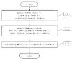
続いて、図18を参照しながら、上述の光学系WLの製造方法について概説する。まず、鏡筒内に、物体側から順に並べて、正の屈折力を有する前群G1と、正の屈折力を有する後群G2とを配置する(ステップST1)。そして、無限遠から近距離物体への合焦の際、前群G1および後群G2が光軸に沿って物体側に移動して、前群G1と後群G2との間隔が変化するように構成する(ステップST2)。さらに、少なくとも上記条件式(1)を満足するように、レンズ鏡筒内に各レンズを配置する(ステップST3)。このような製造方法によれば、合焦の際の像面の変位を抑制して、小型で良好な光学性能を有した光学系を製造することが可能になる。 Next, with reference to FIG. 18, a method of manufacturing the above optical system WL will be outlined. First, in the lens barrel, a front group G1 having a positive refractive power and a rear group G2 having a positive refractive power are arranged in order from the object side (step ST1). Then, when focusing on an object at a short distance from infinity, the front group G1 and the rear group G2 move toward the object side along the optical axis, and the distance between the front group G1 and the rear group G2 changes. Yes (step ST2). Further, each lens is arranged in the lens barrel so as to satisfy at least the conditional expression (1) (step ST3). According to such a manufacturing method, it is possible to suppress the displacement of the image plane at the time of focusing and manufacture a compact optical system having good optical performance.
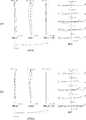
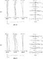
以下、本実施形態の実施例に係る光学系(広角レンズ)WLを図面に基づいて説明する。図1、図3、図5、図7、図9、図11、図13、図15は、第1〜第8実施例に係る
光学系WL{WL(1)〜WL(8)}の構成及び屈折力配分を示す断面図である。各断面図には、無限遠から近距離物体へ合焦する際の、(「無限遠」および「近距離」と併記された)各群の位置が記載されている。Hereinafter, an optical system (wide-angle lens) WL according to an example of this embodiment will be described with reference to the drawings. 1, FIG. 3, FIG. 5, FIG. 7, FIG. 9, FIG. 11, FIG. 13, and FIG. 15, the configurations of the optical systems WL{WL(1) to WL(8)} according to the first to eighth examples. FIG. 6 is a cross-sectional view showing distribution of refractive power. In each cross-sectional view, the position of each group (also described as "infinity" and "short distance") when focusing on an object at infinity from a short distance is described.
これら図1、図3、図5、図7、図9、図11、図13、図15において、各群を符号Gと数字の組み合わせにより、各レンズを符号Lと数字の組み合わせにより、それぞれ表している。この場合において、符号、数字の種類および数が大きくなって煩雑化するのを防止するため、実施例毎にそれぞれ独立して符号と数字の組み合わせを用いてレンズ群等を表している。このため、実施例間で同一の符号と数字の組み合わせが用いられていても、同一の構成であることを意味するものでは無い。 1, FIG. 3, FIG. 5, FIG. 7, FIG. 9, FIG. 11, FIG. 13, and FIG. 15, each group is represented by a combination of reference numeral G and a numeral, and each lens is represented by a combination of reference numeral L and a numeral. ing. In this case, in order to prevent the type and number of symbols and numbers from becoming large and complicated, the lens groups and the like are represented independently by using combinations of symbols and numbers for each embodiment. Therefore, even if the same combination of reference numerals and numbers is used between the embodiments, it does not mean that they have the same configuration.
以下に表1〜表8を示すが、この内、表1は第1実施例、表2は第2実施例、表3は第3実施例、表4は第4実施例、表5は第5実施例、表6は第6実施例、表7は第7実施例、表8は第8実施例における各諸元データを示す表である。各実施例では収差特性の算出対象として、d線(波長λ=587.6nm)、g線(波長λ=435.8nm)を選んでいる。 Tables 1 to 8 are shown below, in which Table 1 is the first embodiment, Table 2 is the second embodiment, Table 3 is the third embodiment, Table 4 is the fourth embodiment, and Table 5 is the first embodiment. 5th Example, Table 6 is a 6th Example, Table 7 is a 7th Example, and Table 8 is a table|surface which shows each specification data in an 8th Example. In each embodiment, the d-line (wavelength λ=587.6 nm) and the g-line (wavelength λ=435.8 nm) are selected as targets for calculating the aberration characteristics.
[全体諸元]の表において、fは無限遠合焦状態の光学系WLにおける全系の焦点距離を示し、FNОはFナンバーを示す。2ωは画角(単位は°(度)で、ωが半画角である)を示し、Yは像高(最大像高)を示す。Bfは無限遠合焦状態の光学系WLにおける最も像側のレンズ面から像面Iまでの光軸上の空気換算距離(バックフォーカス)を示し、TLは無限遠合焦状態の光学系WLにおける最も物体側のレンズ面から像面Iまでの光軸上の距離(全長)を示す。なお、TLにおいて、光学系WLにおける最も像側のレンズ面から像面Iまでは空気換算距離を示す。また、TLおよびBfの値は、後述の[可変間隔データ]において、無限遠合焦状態、近距離(至近距離)合焦状態におけるそれぞれについて示す。 In the table of [Overall Specifications], f indicates the focal length of the entire system in the optical system WL in the infinity focused state, and FNO indicates the F number. 2ω indicates the angle of view (the unit is ° (degrees), and ω is the half angle of view), and Y indicates the image height (maximum image height). Bf represents the air-converted distance (back focus) on the optical axis from the lens surface closest to the image side to the image plane I in the optical system WL in the infinity focused state, and TL in the optical system WL in the infinity focused state. The distance (total length) from the lens surface closest to the object to the image plane I on the optical axis is shown. In TL, the air-equivalent distance is shown from the lens surface closest to the image side in the optical system WL to the image plane I. Further, the values of TL and Bf are shown in [Variable Interval Data] described below for the infinity in-focus state and the short-distance (close-up) in-focus state.
また、X1は合焦の際の前群G1の移動量を示し、X2は合焦の際の後群G2の移動量を示す。各移動量は、物体側から像側へ向かう方向を正とする。ST1は無限遠合焦状態の光学系WLにおける最も物体側のレンズ面から開口絞りSまでの光軸上の距離を示し、BLは無限遠合焦状態の光学系WLにおける最も物体側のレンズ面から最も像側のレンズ面までの光軸上の距離を示す。 Further, X1 indicates the movement amount of the front group G1 at the time of focusing, and X2 indicates the movement amount of the rear group G2 at the time of focusing. Each movement amount is positive in the direction from the object side to the image side. ST1 represents the distance on the optical axis from the lens surface closest to the object in the optical system WL in the infinity focused state to the aperture stop S, and BL represents the lens surface closest to the object in the optical system WL in the infinity focused state. Indicates the distance on the optical axis from to the lens surface closest to the image side.
[レンズ諸元]の表において、面番号は光線の進行する方向に沿った物体側からの光学面の順序を示し、Rは各光学面の曲率半径(曲率中心が像側に位置する面を正の値としている)、Dは各光学面から次の光学面(又は像面)までの光軸上の距離である面間隔、νdは光学部材の材質のd線を基準とするアッベ数、ndは光学部材の材質のd線に対する屈折率を、それぞれ示す。曲率半径の「∞」は平面又は開口を示し、(絞りS)は開口絞りSを示す。空気の屈折率nd=1.00000の記載は省略している。レンズ面が非球面であ
る場合には面番号に*印を付して曲率半径Rの欄には近軸曲率半径を示している。In the table of [lens specifications], the surface number indicates the order of the optical surface from the object side along the traveling direction of the light ray, and R represents the radius of curvature of each optical surface (the surface whose center of curvature is located on the image side). Is a positive value), D is a surface distance which is a distance on the optical axis from each optical surface to the next optical surface (or an image surface), νd is an Abbe number based on the d-line of the material of the optical member, nd represents the refractive index of the material of the optical member with respect to the d-line. The radius of curvature “∞” indicates a plane or an aperture, and (stop S) indicates the aperture stop S. The description of the refractive index of air nd=1.0000 is omitted. When the lens surface is an aspherical surface, the surface number is marked with * and the radius of curvature R column indicates the paraxial radius of curvature.
[非球面データ]の表には、[レンズ諸元]に示した非球面について、その形状を次式(a)で示す。X(y)は非球面の頂点における接平面から高さyにおける非球面上の位置までの光軸方向に沿った距離(ザグ量)を、Rは基準球面の曲率半径(近軸曲率半径)を、κは円錐定数を、Aiは第i次の非球面係数を示す。「E-n」は、「×10-n」を示す。例えば、1.234E-05=1.234×10⁻⁵である。なお、2次の非球面係数A2は0であり、その記載を省略している。In the table of [aspherical surface data], the shape of the aspherical surface shown in [lens specifications] is shown by the following expression (a). X(y) is the distance (zag amount) from the tangent plane at the apex of the aspherical surface to the position on the aspherical surface at the height y along the optical axis direction, and R is the radius of curvature of the reference spherical surface (paraxial radius of curvature). , Κ is a conic constant, and Ai is an i-th order aspherical coefficient. “E-n” indicates “×10−n ”. For example, 1.234E-05=1.234×10⁻⁵ . The quadratic aspherical coefficient A2 is 0, and the description thereof is omitted.
X(y)=(y2/R)/{1+(1−κ×y2/R2)1/2}+A4×y4+A6×y6+A8×y8+A10×y10+A12×y12+A14×y14 ・・・(a)X (y) = (y 2 / R) / {1+ (1-κ × y 2 / R 2) 1/2} + A4 ×
[群データ]の表において、前群G1および後群G2のそれぞれの始面(最も物体側の面)と焦点距離を示す。 In the table of [Group data], the starting surface (the surface closest to the object) and the focal length of each of the front group G1 and the rear group G2 are shown.
[可変間隔データ]の表は、[レンズ諸元]を示す表において面間隔が「可変」となっている面番号iにおける次の面までの面間隔Diを示す。例えば、第1実施例では、面番号8,16での面間隔D8,D16を示す。これらの値は、無限遠合焦状態、近距離(至近距離)合焦状態におけるそれぞれについて示す。 The table of [variable spacing data] shows the surface spacing Di to the next surface at the surface number i where the surface spacing is “variable” in the table showing [lens specifications]. For example, in the first embodiment, the surface distances D8 and D16 at the
[条件式対応値]の表には、上記の条件式(1)〜(6)に対応する値を示す。 The table of [Values corresponding to conditional expressions] shows values corresponding to the above conditional expressions (1) to (6).
以下、全ての諸元値において、掲載されている焦点距離f、曲率半径R、面間隔D、その他の長さ等は、特記のない場合一般に「mm」が使われるが、光学系は比例拡大又は比例縮小しても同等の光学性能が得られるので、これに限られるものではない。 In all of the following specification values, the focal length f, radius of curvature R, surface distance D, and other lengths listed are generally “mm” unless otherwise specified, but the optical system is proportionally enlarged. Alternatively, since the same optical performance can be obtained even if the proportion is reduced, the invention is not limited to this.
ここまでの表の説明は全ての実施例において共通であり、以下での重複する説明は省略する。 The description of the table up to this point is common to all the embodiments, and the duplicated description below is omitted.
(第1実施例)
第1実施例について、図1〜図2および表1を用いて説明する。図1は、本実施形態の第1実施例に係る光学系のレンズ構成を示す図である。第1実施例に係る光学系WL(1)は、物体側から順に並んだ、正の屈折力を有する前群G1と、正の屈折力を有する後群G2とから構成されている。各群の記号に付けている符号(+)もしくは(−)は各群の屈折力を示し、このことは以下の全ての実施例でも同様である。(First embodiment)
The first embodiment will be described with reference to FIGS. 1 and 2 and Table 1. FIG. 1 is a diagram showing a lens configuration of an optical system according to Example 1 of the present embodiment. The optical system WL(1) according to the first example includes a front group G1 having a positive refractive power and a rear group G2 having a positive refractive power, which are arranged in order from the object side. The symbol (+) or (−) attached to the symbol of each group indicates the refractive power of each group, and this is the same in all the examples below.
前群G1は、物体側から順に並んだ、物体側に凸面を向けたメニスカス形状の第1の負レンズL11と、開口絞りSと、両凹形状の第2の負レンズL12および両凸形状の第1の正レンズL13からなる接合レンズと、両凸形状の第2の正レンズL14と、から構成される。第1の負レンズL11は、物体側のレンズ面が非球面である。 The front group G1 includes, in order from the object side, a meniscus-shaped first negative lens L11 having a convex surface directed toward the object side, an aperture stop S, a biconcave second negative lens L12, and a biconvex shape. It is composed of a cemented lens composed of the first positive lens L13 and a biconvex second positive lens L14. The first negative lens L11 has an aspherical lens surface on the object side.
後群G2は、物体側から順に並んだ、両凸形状の第1の正レンズL21および両凹形状の第1の負レンズL22からなる接合レンズと、像側に凸面を向けたメニスカス形状の第2の正レンズL23および像側に凸面を向けたメニスカス形状の第2の負レンズL24からなる接合レンズと、像側に凸面を向けたメニスカス形状の第3の正レンズL25と、から構成される。第3の正レンズL25は、像側のレンズ面が非球面である。 The rear group G2 includes, in order from the object side, a cemented lens including a biconvex first positive lens L21 and a biconcave first negative lens L22, and a meniscus-shaped first lens having a convex surface facing the image side. Two positive lenses L23 and a meniscus-shaped second negative lens L24 having a convex surface facing the image side, and a meniscus-shaped third positive lens L25 having a convex surface facing the image side. .. The third positive lens L25 has an aspheric lens surface on the image side.
後群G2の像側に、像面Iが配置される。後群G2と像面Iとの間における像面Iの近傍に、像面Iに配設される撮像素子(例えば、CCDやCMOS等)の限界解像以上の空間周波数をカットするためのローパスフィルタFLが配置される。第1実施例に係る光学系WL(1)では、無限遠から近距離物体への合焦の際、前群G1および後群G2が異なる移動量で光軸に沿って物体側へ移動し、前群G1と後群G2との間隔が変化する(大きくなる)ように構成される。 The image plane I is disposed on the image side of the rear group G2. Near the image plane I between the rear group G2 and the image plane I, a low pass for cutting spatial frequencies above the limit resolution of an image sensor (eg, CCD or CMOS) arranged on the image plane I. The filter FL is arranged. In the optical system WL(1) according to the first example, when focusing on an object at a short distance from infinity, the front group G1 and the rear group G2 move to the object side along the optical axis with different movement amounts, and The distance between the group G1 and the rear group G2 is configured to change (become larger).
以下の表1に、第1実施例に係る光学系の諸元の値を掲げる。 Table 1 below lists values of specifications of the optical system according to the first example.
(表1)
[全体諸元]
f=24.88
FNO=1.87
2ω=60.1
Y=14.25
Bf=14.687
TL=44.867
X1=-2.466
X2=-1.925
ST1=3.701
BL=30.180
[レンズ諸元]
面番号 R D νd nd
1* 30.8401 1.5000 31.16 1.688930
2 20.5905 2.2008
3 ∞ 2.6833 (絞りS)
4 -19.3699 0.8001 40.98 1.581440
5 27.7890 3.1806 52.33 1.755000
6 -30.9598 0.1001
7 52.2934 3.2581 40.66 1.883000
8 -32.4827 D8(可変)
9 36.5887 5.0663 40.66 1.883000
10 -18.9352 0.8001 30.13 1.698950
11 19.9997 4.3541
12 -19.0168 2.0763 46.59 1.816000
13 -13.5233 0.8004 30.13 1.698950
14 -254.9861 0.8000
15 -71.2612 2.0000 40.10 1.851348
16* -21.9663 D16(可変)
17 ∞ 2.0000 63.88 1.516800
18 ∞ 0.1000
[非球面データ]
第1面
κ=1.0000,A4=-5.34672E-05,A6=-6.49809E-08
A8=-4.57464E-09,A10=4.18288E-11,A12=-1.57370E-13,A14=0.00000E+00
第16面
κ=1.0000,A4=4.49624E-05,A6=1.25196E-08
A8=3.83338E-09,A10=-3.15603E-11,A12=1.34880E-13,A14=0.00000E+00
[群データ]
群 始面 焦点距離
G1 1 24.38
G2 9 916.87
[可変間隔データ]
無限遠合焦状態 近距離合焦状態
f=24.88 β=-0.1
D0 ∞ 261.29
D8 0.559 1.101
D16 13.268 15.193
Bf(air) 14.687 16.612
TL(air) 44.867 47.332
[条件式対応値]
条件式(1) X1/X2=1.281
条件式(2) Bf/f=0.590
条件式(3) ST1/TL=0.082
条件式(4) Dinf/Dmod=0.508
条件式(5) Y/BL=0.472
条件式(6) TL/(FNO×Bf)=1.632(Table 1)
[Overall specifications]
f=24.88
FNO=1.87
2ω = 60.1
Y = 14.25
Bf=14.687
TL=44.867
X1=-2.466
X2 = -1.925
ST1 = 3.701
BL=30.180
[Specifications of lens]
Surface number RD νd nd
1* 30.8401 1.5000 31.16 1.688930
2 20.5905 2.2008
3 ∞ 2.6833 (Aperture S)
4 -19.3699 0.8001 40.98 1.581440
5 27.7890 3.1806 52.33 1.755000
6 -30.9598 0.1001
7 52.2934 3.2581 40.66 1.883000
8 -32.4827 D8 (variable)
9 36.5887 5.0663 40.66 1.883000
10 -18.9352 0.8001 30.13 1.698950
11 19.9997 4.3541
12 -19.0168 2.0763 46.59 1.816000
13 -13.5233 0.8004 30.13 1.698950
14 -254.9861 0.8000
15 -71.2612 2.0000 40.10 1.851348
16* -21.9663 D16 (variable)
17 ∞ 2.0000 63.88 1.516800
18 ∞ 0.1000
[Aspherical data]
1st surface κ=1.0000,A4=-5.34672E-05,A6=-6.49809E-08
A8=-4.57464E-09,A10=4.18288E-11,A12=-1.57370E-13,A14=0.00000E+00
16th surface κ=1.0000, A4=4.49624E-05, A6=1.25196E-08
A8=3.83338E-09,A10=-3.15603E-11,A12=1.34880E-13,A14=0.00000E+00
[Group data]
Focal length of group start surface
G2 9 916.87
[Variable interval data]
Focused at infinity Focused at close range
f=24.88 β=-0.1
D0 ∞ 261.29
D8 0.559 1.101
D16 13.268 15.193
Bf(air) 14.687 16.612
TL(air) 44.867 47.332
[Value corresponding to conditional expression]
Conditional expression (1) X1/X2=1.281
Conditional expression (2) Bf/f=0.590
Conditional expression (3) ST1/TL=0.082
Conditional expression (4) Dinf/Dmod=0.508
Conditional expression (5) Y/BL=0.472
Conditional expression (6) TL/(FNO×Bf)=1.632
図2(a)は、第1実施例に係る光学系の無限遠合焦時の諸収差図である。図2(a)の各収差図において、FNOはFナンバー、Aは半画角をそれぞれ示す。なお、球面収差図では最大口径に対応するFナンバーの値を示し、非点収差図および歪曲収差図では半画角の最大値をそれぞれ示し、横収差図では各半画角の値を示す。図2(b)は、第1実施例に係る光学系の近距離(至近距離)合焦時の諸収差図である。図2(b)の各収差図において、NAは開口数、H0は物体高をそれぞれ示す。なお、球面収差図では最大口径に対応する開口数の値を示し、非点収差図および歪曲収差図では物体高の最大値をそれぞれ示し、横収差図では各物体高の値を示す。また、図2(a)および図2(b)の各収差図において、dはd線(波長λ=587.6nm)、gはg線(波長λ=435.8nm)をそれぞれ示す。非点収差図において、実線はサジタル像面、破線はメリディオナル像面をそれぞれ示す。なお、以下に示す各実施例の収差図においても、本実施例と同様の符号を用い、重複する説明は省略する。 FIG. 2A is a diagram of various types of aberration when the optical system according to Example 1 is in focus at infinity. In each aberration diagram of FIG. 2A, FNO indicates an F number, and A indicates a half angle of view. The spherical aberration diagram shows the F-number value corresponding to the maximum aperture, the astigmatism diagram and the distortion diagram show the maximum half-angle of view, and the lateral aberration diagram shows the value of each half-angle of view. FIG. 2B is a diagram of various types of aberration when the optical system according to Example 1 focuses on a short distance (close-up distance). In each aberration diagram of FIG. 2B, NA represents the numerical aperture and H0 represents the object height. The spherical aberration diagram shows the numerical aperture value corresponding to the maximum aperture, the astigmatism diagram and the distortion diagram show the maximum value of the object height, and the lateral aberration diagram shows the value of each object height. 2A and 2B, d indicates the d line (wavelength λ=587.6 nm) and g indicates the g line (wavelength λ=435.8 nm). In the astigmatism diagram, the solid line shows the sagittal image plane, and the broken line shows the meridional image plane. In the aberration diagrams of the respective examples shown below, the same reference numerals as those in the present example are used, and the duplicated description will be omitted.
各収差図より、第1実施例に係る光学系は、諸収差を良好に補正し優れた結像性能を有していることがわかる。 From each aberration diagram, it is understood that the optical system according to Example 1 has excellent imaging performance by satisfactorily correcting various aberrations.
(第2実施例)
第2実施例について、図3〜図4および表2を用いて説明する。図3は、本実施形態の第2実施例に係る光学系のレンズ構成を示す図である。第2実施例に係る光学系WL(2)は、物体側から順に並んだ、正の屈折力を有する前群G1と、正の屈折力を有する後群G2とから構成されている。(Second embodiment)
The second embodiment will be described with reference to FIGS. 3 to 4 and Table 2. FIG. 3 is a diagram showing a lens configuration of an optical system according to Example 2 of the present embodiment. The optical system WL(2) according to the second example includes a front group G1 having a positive refractive power and a rear group G2 having a positive refractive power, which are arranged in order from the object side.
前群G1は、物体側から順に並んだ、物体側に凸面を向けたメニスカス形状の第1の負レンズL11と、開口絞りSと、両凹形状の第2の負レンズL12および両凸形状の第1の正レンズL13からなる接合レンズと、両凸形状の第2の正レンズL14と、から構成される。第1の負レンズL11は、物体側のレンズ面が非球面である。 The front group G1 includes, in order from the object side, a meniscus-shaped first negative lens L11 having a convex surface directed toward the object side, an aperture stop S, a biconcave second negative lens L12, and a biconvex shape. It is composed of a cemented lens composed of the first positive lens L13 and a biconvex second positive lens L14. The first negative lens L11 has an aspherical lens surface on the object side.
後群G2は、物体側から順に並んだ、両凸形状の第1の正レンズL21および両凹形状の第1の負レンズL22からなる接合レンズと、像側に凸面を向けたメニスカス形状の第2の負レンズL23と、像側に凸面を向けたメニスカス形状の第2の正レンズL24と、から構成される。第2の正レンズL24は、像側のレンズ面が非球面である。 The rear group G2 includes, in order from the object side, a cemented lens including a biconvex first positive lens L21 and a biconcave first negative lens L22, and a meniscus-shaped first lens having a convex surface facing the image side. The second negative lens L23 and the meniscus second positive lens L24 having a convex surface facing the image side. The image side lens surface of the second positive lens L24 is an aspherical surface.
後群G2の像側に、像面Iが配置される。後群G2と像面Iとの間における像面Iの近傍に、像面Iに配設される撮像素子(例えば、CCDやCMOS等)の限界解像以上の空間周波数をカットするためのローパスフィルタFLが配置される。第2実施例に係る光学系WL(2)では、無限遠から近距離物体への合焦の際、前群G1および後群G2が異なる移動量で光軸に沿って物体側へ移動し、前群G1と後群G2との間隔が変化する(大きくなる)ように構成される。 The image plane I is disposed on the image side of the rear group G2. Near the image plane I between the rear group G2 and the image plane I, a low pass for cutting spatial frequencies above the limit resolution of an image sensor (eg, CCD or CMOS) arranged on the image plane I. The filter FL is arranged. In the optical system WL(2) according to the second example, when focusing on an object at a short distance from infinity, the front group G1 and the rear group G2 move to the object side along the optical axis with different movement amounts, and The distance between the group G1 and the rear group G2 is configured to change (become larger).
以下の表2に、第2実施例に係る光学系の諸元の値を掲げる。 Table 2 below lists values of specifications of the optical system according to the second example.
(表2)
[全体諸元]
f=24.87
FNO=1.85
2ω=60.3
Y=14.25
Bf=14.314
TL=44.835
X1=-2.548
X2=-1.927
ST1=3.916
BL=30.521
[レンズ諸元]
面番号 R D νd nd
1* 25.5040 1.5000 31.16 1.688930
2 18.6960 2.4157
3 ∞ 2.6833 (絞りS)
4 -15.7969 0.8001 38.03 1.603420
5 60.8750 3.0479 52.33 1.755000
6 -24.1051 0.1001
7 57.7654 3.2320 40.66 1.883000
8 -31.5105 D8(可変)
9 37.6601 5.8206 40.66 1.883000
10 -16.5976 0.7993 30.13 1.698950
11 20.0514 4.7260
12 -17.8284 0.8002 27.57 1.755200
13 -93.7042 1.0000
14 -77.4574 2.2166 40.10 1.851348
15* -19.9971 D15(可変)
16 ∞ 2.0000 63.88 1.516800
17 ∞ 0.1000
[非球面データ]
第1面
κ=1.0000,A4=-4.88778E-05,A6=2.20240E-08
A8=-5.16914E-09,A10=3.00275E-11,A12=0.00000E+00,A14=0.00000E+00
第15面
κ=1.0000,A4=4.38327E-05,A6=5.96629E-09
A8=3.39332E-09,A10=-8.97554E-12,A12=-2.19810E-13,A14=1.84040E-15
[群データ]
群 始面 焦点距離
G1 1 26.15
G2 9 325.65
[可変間隔データ]
無限遠合焦状態 近距離合焦状態
f=24.87 β=-0.1
D0 ∞ 261.29
D8 1.379 2.001
D15 12.896 14.823
Bf(air) 14.314 16.241
TL(air) 44.835 47.383
[条件式対応値]
条件式(1) X1/X2=1.323
条件式(2) Bf/f=0.576
条件式(3) ST1/TL=0.087
条件式(4) Dinf/Dmod=0.689
条件式(5) Y/BL=0.467
条件式(6) TL/(FNO×Bf)=1.693(Table 2)
[Overall specifications]
f=24.87
FNO=1.85
2ω = 60.3
Y = 14.25
Bf = 14.314
TL=44.835
X1=-2.548
X2 = -1.927
ST1 = 3.916
BL=30.521
[Specifications of lens]
Surface number RD νd nd
1* 25.5040 1.5000 31.16 1.688930
2 18.6960 2.4157
3 ∞ 2.6833 (Aperture S)
4 -15.7969 0.8001 38.03 1.603420
5 60.8750 3.0479 52.33 1.755000
6 -24.1051 0.1001
7 57.7654 3.2320 40.66 1.883000
8 -31.5105 D8 (variable)
9 37.6601 5.8206 40.66 1.883000
10 -16.5976 0.7993 30.13 1.698950
11 20.0514 4.7260
12 -17.8284 0.8002 27.57 1.755200
13 -93.7042 1.0000
14 -77.4574 2.2166 40.10 1.851348
15* -19.9971 D15 (variable)
16 ∞ 2.0000 63.88 1.516800
17 ∞ 0.1000
[Aspherical data]
1st surface κ=1.0000,A4=-4.88778E-05,A6=2.20240E-08
A8=-5.16914E-09,A10=3.00275E-11,A12=0.00000E+00,A14=0.00000E+00
15th surface κ=1.0000, A4=4.38327E-05, A6=5.96629E-09
A8=3.39332E-09,A10=-8.97554E-12,A12=-2.19810E-13,A14=1.84040E-15
[Group data]
Focal length of group start surface
G2 9 325.65
[Variable interval data]
Focused at infinity Focused at close range
f=24.87 β=-0.1
D0 ∞ 261.29
D8 1.379 2.001
D15 12.896 14.823
Bf(air) 14.314 16.241
TL(air) 44.835 47.383
[Value corresponding to conditional expression]
Conditional expression (1) X1/X2=1.323
Conditional expression (2) Bf/f=0.576
Conditional expression (3) ST1/TL=0.087
Conditional expression (4) Dinf/Dmod=0.689
Conditional expression (5) Y/BL=0.467
Conditional expression (6) TL/(FNO×Bf)=1.693
図4(a)は、第2実施例に係る光学系の無限遠合焦時の諸収差図である。図4(b)は、第2実施例に係る光学系の近距離(至近距離)合焦時の諸収差図である。各収差図より、第2実施例に係る光学系は、諸収差を良好に補正し優れた結像性能を有していることがわかる。 FIG. 4A is a diagram of various types of aberration when the optical system according to Example 2 is in focus at infinity. FIG. 4B is a diagram of various types of aberration when the optical system according to the second example focuses at a short distance (close-up distance). It is understood from the aberration diagrams that the optical system according to the second example has excellent imaging performance by satisfactorily correcting various aberrations.
(第3実施例)
第3実施例について、図5〜図6および表3を用いて説明する。図5は、本実施形態の第3実施例に係る光学系のレンズ構成を示す図である。第3実施例に係る光学系WL(3)は、物体側から順に並んだ、正の屈折力を有する前群G1と、正の屈折力を有する後群G2とから構成されている。(Third embodiment)
The third embodiment will be described with reference to FIGS. 5 to 6 and Table 3. FIG. 5 is a diagram showing a lens configuration of an optical system according to Example 3 of the present embodiment. The optical system WL(3) according to the third example includes a front group G1 having a positive refractive power and a rear group G2 having a positive refractive power, which are arranged in order from the object side.
前群G1は、物体側から順に並んだ、物体側に凸面を向けたメニスカス形状の第1の負レンズL11と、開口絞りSと、両凹形状の第2の負レンズL12および両凸形状の第1の正レンズL13からなる接合レンズと、両凸形状の第2の正レンズL14と、から構成される。第1の負レンズL11は、物体側のレンズ面が非球面である。 The front group G1 includes, in order from the object side, a meniscus-shaped first negative lens L11 having a convex surface directed toward the object side, an aperture stop S, a biconcave second negative lens L12, and a biconvex shape. It is composed of a cemented lens composed of the first positive lens L13 and a biconvex second positive lens L14. The first negative lens L11 has an aspherical lens surface on the object side.
後群G2は、物体側から順に並んだ、両凸形状の第1の正レンズL21および両凹形状の第1の負レンズL22からなる接合レンズと、両凹形状の第2の負レンズL23と、像側に凸面を向けたメニスカス形状の第2の正レンズL24と、から構成される。第2の正レンズL24は、像側のレンズ面が非球面である。 The rear group G2 includes, in order from the object side, a cemented lens including a biconvex first positive lens L21 and a biconcave first negative lens L22, and a biconcave second negative lens L23. , A meniscus-shaped second positive lens L24 having a convex surface directed toward the image side. The image side lens surface of the second positive lens L24 is an aspherical surface.
後群G2の像側に、像面Iが配置される。後群G2と像面Iとの間における像面Iの近傍に、像面Iに配設される撮像素子(例えば、CCDやCMOS等)の限界解像以上の空間周波数をカットするためのローパスフィルタFLが配置される。第3実施例に係る光学系WL(3)では、無限遠から近距離物体への合焦の際、前群G1および後群G2が異なる移動量で光軸に沿って物体側へ移動し、前群G1と後群G2との間隔が変化する(大きくなる)ように構成される。 The image plane I is disposed on the image side of the rear group G2. Near the image plane I between the rear group G2 and the image plane I, a low pass for cutting spatial frequencies above the limit resolution of an image sensor (eg, CCD or CMOS) arranged on the image plane I. The filter FL is arranged. In the optical system WL(3) according to the third example, when focusing on an object at a short distance from infinity, the front group G1 and the rear group G2 move to the object side along the optical axis with different movement amounts, and The distance between the group G1 and the rear group G2 is configured to change (become larger).
以下の表3に、第3実施例に係る光学系の諸元の値を掲げる。 Table 3 below lists values of specifications of the optical system according to the third example.
(表3)
[全体諸元]
f=24.47
FNO=1.80
2ω=64.7
Y=15.30
Bf=14.174
TL=44.984
X1=-2.513
X2=-1.854
ST1=3.918
BL=30.810
[レンズ諸元]
面番号 R D νd nd
1* 33.6258 1.5000 31.16 1.688930
2 21.3183 2.4178
3 ∞ 2.6833 (絞りS)
4 -18.3419 0.7972 38.03 1.603420
5 52.2261 3.2276 52.33 1.755000
6 -27.2223 0.0975
7 58.8778 3.2618 40.66 1.883000
8 -30.7587 D8(可変)
9 34.5854 5.7924 40.66 1.883000
10 -17.5323 0.8042 30.13 1.698950
11 19.2264 4.5520
12 -19.3254 0.8777 27.57 1.755200
13 2309.2099 1.0000
14 -141.6693 2.4035 40.10 1.851348
15* -20.2687 D15(可変)
16 ∞ 2.0000 63.88 1.516800
17 ∞ 0.1000
[非球面データ]
第1面
κ=1.0000,A4=-5.40060E-05,A6=-7.45960E-08
A8=-3.30700E-09,A10=2.14440E-11,A12=0.00000E+00,A14=0.00000E+00
第15面
κ=1.0000,A4=4.41290E-05,A6=-1.40220E-08
A8=3.73110E-09,A10=-8.21740E-12,A12=-2.66630E-13,A14=2.18070E-15
[群データ]
群 始面 焦点距離
G1 1 25.78
G2 9 319.15
[可変間隔データ]
無限遠合焦状態 近距離合焦状態
f=24.47 β=-0.1
D0 ∞ 256.93
D8 1.395 2.054
D15 12.755 14.609
Bf(air) 14.174 16.028
TL(air) 44.984 47.497
[条件式対応値]
条件式(1) X1/X2=1.356
条件式(2) Bf/f=0.579
条件式(3) ST1/TL=0.087
条件式(4) Dinf/Dmod=0.375
条件式(5) Y/BL=0.497
条件式(6) TL/(FNO×Bf)=1.763(Table 3)
[Overall specifications]
f=24.47
FNO=1.80
2ω = 64.7
Y = 15.30
Bf = 14.174
TL=44.984
X1 = -2.513
X2 = -1.854
ST1 = 3.918
BL=30.810
[Specifications of lens]
Surface number RD νd nd
1* 33.6258 1.5000 31.16 1.688930
2 21.3183 2.4178
3 ∞ 2.6833 (Aperture S)
4 -18.3419 0.7972 38.03 1.603420
5 52.2261 3.2276 52.33 1.755000
6 -27.2223 0.0975
7 58.8778 3.2618 40.66 1.883000
8 -30.7587 D8 (variable)
9 34.5854 5.7924 40.66 1.883000
10 -17.5323 0.8042 30.13 1.698950
11 19.2264 4.5520
12 -19.3254 0.8777 27.57 1.755200
13 2309.2099 1.0000
14 -141.6693 2.4035 40.10 1.851348
15*-20.2687 D15 (variable)
16 ∞ 2.0000 63.88 1.516800
17 ∞ 0.1000
[Aspherical data]
1st surface κ=1.0000,A4=-5.40060E-05,A6=-7.45960E-08
A8=-3.30700E-09,A10=2.14440E-11,A12=0.00000E+00,A14=0.00000E+00
15th surface κ=1.0000, A4=4.41290E-05, A6=-1.40220E-08
A8=3.73110E-09,A10=-8.21740E-12,A12=-2.66630E-13,A14=2.18070E-15
[Group data]
Focal length of group start surface
G2 9 319.15
[Variable interval data]
Focused at infinity Focused at close range
f=24.47 β=-0.1
D0 ∞ 256.93
D8 1.395 2.054
D15 12.755 14.609
Bf(air) 14.174 16.028
TL(air) 44.984 47.497
[Value corresponding to conditional expression]
Conditional expression (1) X1/X2=1.356
Conditional expression (2) Bf/f=0.579
Conditional expression (3) ST1/TL=0.087
Conditional expression (4) Dinf/Dmod=0.375
Conditional expression (5) Y/BL=0.497
Conditional expression (6) TL/(FNO×Bf)=1.763
図6(a)は、第3実施例に係る光学系の無限遠合焦時の諸収差図である。図6(b)は、第3実施例に係る光学系の近距離(至近距離)合焦時の諸収差図である。各収差図より、第3実施例に係る光学系は、諸収差を良好に補正し優れた結像性能を有していることがわかる。 FIG. 6A is a diagram of various types of aberration when the optical system according to Example 3 is in focus at infinity. FIG. 6B is a diagram of various types of aberration when the optical system according to the third example focuses at a short distance (close-up distance). It is understood from the aberration diagrams that the optical system according to Example 3 has excellent imaging performance by satisfactorily correcting various aberrations.
(第4実施例)
第4実施例について、図7〜図8および表4を用いて説明する。図7は、本実施形態の第4実施例に係る光学系のレンズ構成を示す図である。第4実施例に係る光学系WL(4)は、物体側から順に並んだ、正の屈折力を有する前群G1と、正の屈折力を有する後群
G2とから構成されている。(Fourth embodiment)
A fourth embodiment will be described with reference to FIGS. 7 to 8 and Table 4. FIG. 7 is a diagram showing a lens configuration of an optical system according to Example 4 of the present embodiment. The optical system WL(4) according to the fourth example includes a front group G1 having a positive refractive power and a rear group G2 having a positive refractive power, which are arranged in order from the object side.
前群G1は、物体側から順に並んだ、両凹形状の第1の負レンズL11と、両凸形状の第1の正レンズL12と、開口絞りSと、両凹形状の第2の負レンズL13および両凸形状の第2の正レンズL14からなる接合レンズと、像側に凸面を向けたメニスカス形状の第3の負レンズL15と、から構成される。第3の負レンズL15は、像側のレンズ面が非球面である。 The front group G1 includes, in order from the object side, a biconcave first negative lens L11, a biconvex first positive lens L12, an aperture stop S, and a biconcave second negative lens. It is composed of a cemented lens including L13 and a biconvex second positive lens L14, and a meniscus third negative lens L15 having a convex surface facing the image side. The third negative lens L15 has an aspherical lens surface on the image side.
後群G2は、物体側から順に並んだ、両凸形状の第1の正レンズL21および両凹形状の第1の負レンズL22からなる接合レンズと、両凹形状の第2の負レンズL23と、両凸形状の第2の正レンズL24と、から構成される。第2の正レンズL24は、像側のレンズ面が非球面である。 The rear group G2 includes, in order from the object side, a cemented lens including a biconvex first positive lens L21 and a biconcave first negative lens L22, and a biconcave second negative lens L23. , A biconvex second positive lens L24. The image side lens surface of the second positive lens L24 is an aspherical surface.
後群G2の像側に、像面Iが配置される。後群G2と像面Iとの間における像面Iの近傍に、像面Iに配設される撮像素子(例えば、CCDやCMOS等)の限界解像以上の空間周波数をカットするためのローパスフィルタFLが配置される。第4実施例に係る光学系WL(4)では、無限遠から近距離物体への合焦の際、前群G1および後群G2が異なる移動量で光軸に沿って物体側へ移動し、前群G1と後群G2との間隔が変化する(大きくなる)ように構成される。 The image plane I is disposed on the image side of the rear group G2. Near the image plane I between the rear group G2 and the image plane I, a low pass for cutting spatial frequencies above the limit resolution of an image sensor (eg, CCD or CMOS) arranged on the image plane I. The filter FL is arranged. In the optical system WL(4) according to the fourth example, when focusing on an object at a short distance from infinity, the front group G1 and the rear group G2 move to the object side along the optical axis with different movement amounts, and The distance between the group G1 and the rear group G2 is configured to change (become larger).
以下の表4に、第4実施例に係る光学系の諸元の値を掲げる。 Table 4 below lists values of specifications of the optical system according to the fourth example.
(表4)
[全体諸元]
f=24.97
FNO=1.85
2ω=62.1
Y=14.25
Bf=14.318
TL=44.678
X1=-3.115
X2=-2.382
ST1=6.433
BL=30.360
[レンズ諸元]
面番号 R D νd nd
1 -23.5865 1.0000 41.51 1.575010
2 32.5087 0.9332
3 20.7551 3.5088 40.66 1.883000
4 -45.6852 1.0000
5 ∞ 2.0111 (絞りS)
6 -30.3720 0.8000 32.18 1.672700
7 15.9804 3.7857 40.66 1.883000
8 -34.7764 1.0000
9 -23.1553 0.8000 31.16 1.688930
10* -100.1049 D10(可変)
11 34.2710 5.2717 40.66 1.883000
12 -13.3880 0.8000 32.18 1.672700
13 31.6442 3.9709
14 -16.5099 0.8000 33.72 1.647690
15 104.7860 0.1000
16 62.8584 4.2211 40.10 1.851348
17* -21.0915 D17(可変)
18 ∞ 2.0000 63.88 1.516800
19 ∞ 0.1000
[非球面データ]
第10面
κ=1.0000,A4=7.09969E-05,A6=5.82420E-08
A8=3.73981E-09,A10=-1.74407E-11,A12=0.00000E+00,A14=0.00000E+00
第17面
κ=1.0000,A4=3.72602E-05,A6=-2.34539E-08
A8=1.32257E-09,A10=-6.49301E-12,A12=0.00000E+00,A14=0.00000E+00
[群データ]
群 始面 焦点距離
G1 1 57.97
G2 11 34.64
[可変間隔データ]
無限遠合焦状態 近距離合焦状態
f=24.97 β=-0.1
D0 ∞ 263.17
D10 0.358 1.090
D17 12.899 15.281
Bf(air) 14.318 16.700
TL(air) 44.678 47.792
[条件式対応値]
条件式(1) X1/X2=1.307
条件式(2) Bf/f=0.573
条件式(3) ST1/TL=0.144
条件式(4) Dinf/Dmod=0.328
条件式(5) Y/BL=0.469
条件式(6) TL/(FNO×Bf)=1.687(Table 4)
[Overall specifications]
f=24.97
FNO=1.85
2ω = 62.1
Y = 14.25
Bf = 14.318
TL=44.678
X1 = -3.115
X2 = -2.382
ST1 = 6.433
BL=30.360
[Specifications of lens]
Surface number RD νd nd
1 -23.5865 1.0000 41.51 1.575010
2 32.5087 0.9332
3 20.7551 3.5088 40.66 1.883000
4 -45.6852 1.0000
5 ∞ 2.0111 (Aperture S)
6 -30.3720 0.8000 32.18 1.672700
7 15.9804 3.7857 40.66 1.883000
8 -34.7764 1.0000
9 -23.1553 0.8000 31.16 1.688930
10*-100.1049 D10 (variable)
11 34.2710 5.2717 40.66 1.883000
12 -13.3880 0.8000 32.18 1.672700
13 31.6442 3.9709
14 -16.5099 0.8000 33.72 1.647690
15 104.7860 0.1000
16 62.8584 4.2211 40.10 1.851348
17* -21.0915 D17 (variable)
18 ∞ 2.0000 63.88 1.516800
19 ∞ 0.1000
[Aspherical data]
10th surface κ=1.0000, A4=7.09969E-05, A6=5.82420E-08
A8=3.73981E-09,A10=-1.74407E-11,A12=0.00000E+00,A14=0.00000E+00
17th surface κ=1.0000, A4=3.72602E-05, A6=-2.34539E-08
A8=1.32257E-09,A10=-6.49301E-12,A12=0.00000E+00,A14=0.00000E+00
[Group data]
Focal length of group start surface
[Variable interval data]
Focused at infinity Focused at close range
f=24.97 β=-0.1
D0 ∞ 263.17
D10 0.358 1.090
D17 12.899 15.281
Bf(air) 14.318 16.700
TL(air) 44.678 47.792
[Value corresponding to conditional expression]
Conditional expression (1) X1/X2=1.307
Conditional expression (2) Bf/f=0.573
Conditional expression (3) ST1/TL=0.144
Conditional expression (4) Dinf/Dmod=0.328
Conditional expression (5) Y/BL=0.469
Conditional expression (6) TL/(FNO×Bf)=1.687
図8(a)は、第4実施例に係る光学系の無限遠合焦時の諸収差図である。図8(b)は、第4実施例に係る光学系の近距離(至近距離)合焦時の諸収差図である。各収差図より、第4実施例に係る光学系は、諸収差を良好に補正し優れた結像性能を有していることがわかる。 FIG. 8A is a diagram of various types of aberration when the optical system according to Example 4 is in focus at infinity. FIG. 8B is a diagram of various types of aberration when the optical system according to the fourth example focuses at a short distance (close-up distance). From each aberration diagram, it can be seen that the optical system according to Example 4 has excellent imaging performance by satisfactorily correcting various aberrations.
(第5実施例)
第5実施例について、図9〜図10および表5を用いて説明する。図9は、本実施形態の第5実施例に係る光学系のレンズ構成を示す図である。第5実施例に係る光学系WL(5)は、物体側から順に並んだ、正の屈折力を有する前群G1と、正の屈折力を有する後群G2とから構成されている。(Fifth embodiment)
A fifth embodiment will be described with reference to FIGS. 9 to 10 and Table 5. FIG. 9 is a diagram showing a lens configuration of an optical system according to Example 5 of the present embodiment. The optical system WL(5) according to the fifth example includes a front group G1 having a positive refractive power and a rear group G2 having a positive refractive power, which are arranged in order from the object side.
前群G1は、物体側から順に並んだ、物体側に凸面を向けたメニスカス形状の負レンズL11と、物体側に凸面を向けたメニスカス形状の正レンズL12と、から構成される。 The front group G1 is composed of a meniscus negative lens L11 having a convex surface facing the object side and a meniscus positive lens L12 having a convex surface facing the object side, which are arranged in order from the object side.
後群G2は、物体側から順に並んだ、開口絞りSと、両凹形状の第1の負レンズL21および両凸形状の第1の正レンズL22からなる接合レンズと、物体側に凸面を向けたメニスカス形状の第2の負レンズL23と、両凹形状の第3の負レンズL24および両凸形状の第2の正レンズL25からなる接合レンズと、両凹形状の第4の負レンズL26と、
両凸形状の第3の正レンズL27と、から構成される。第2の負レンズL23は、像側のレンズ面が非球面である。第4の負レンズL26は、物体側のレンズ面が非球面である。第3の正レンズL27は、像側のレンズ面が非球面である。The rear group G2 includes an aperture stop S, a cemented lens including a biconcave first negative lens L21 and a biconvex first positive lens L22, and a convex surface directed toward the object side, which are arranged in order from the object side. A second negative lens L23 having a meniscus shape, a cemented lens including a third negative lens L24 having a biconcave shape and a second positive lens L25 having a biconvex shape, and a fourth negative lens L26 having a biconcave shape. ,
And a third positive lens L27 having a biconvex shape. The image surface of the second negative lens L23 is an aspherical surface. The fourth negative lens L26 has an aspherical lens surface on the object side. The image side lens surface of the third positive lens L27 is aspheric.
後群G2の像側に、像面Iが配置される。後群G2と像面Iとの間における像面Iの近傍に、像面Iに配設される撮像素子(例えば、CCDやCMOS等)の限界解像以上の空間周波数をカットするためのローパスフィルタFLが配置される。第5実施例に係る光学系WL(5)では、無限遠から近距離物体への合焦の際、前群G1および後群G2が異なる移動量で光軸に沿って物体側へ移動し、前群G1と後群G2との間隔が変化する(大きくなる)ように構成される。 The image plane I is disposed on the image side of the rear group G2. Near the image plane I between the rear group G2 and the image plane I, a low pass for cutting spatial frequencies above the limit resolution of an image sensor (eg, CCD or CMOS) arranged on the image plane I. The filter FL is arranged. In the optical system WL(5) according to the fifth example, when focusing on an object at a short distance from infinity, the front group G1 and the rear group G2 move to the object side along the optical axis with different movement amounts, and The distance between the group G1 and the rear group G2 is configured to change (become larger).
以下の表5に、第5実施例に係る光学系の諸元の値を掲げる。 Table 5 below lists values of specifications of the optical system according to the fifth example.
(表5)
[全体諸元]
f=30.54
FNO=2.09
2ω=53.0
Y=15.00
Bf=18.311
TL=47.320
X1=-5.716
X2=-2.286
ST1=7.414
BL=29.009
[レンズ諸元]
面番号 R D νd nd
1 55.0636 0.8000 29.57 1.717360
2 22.1561 0.3000
3 23.9630 1.8848 40.66 1.883000
4 643.3073 D4(可変)
5 ∞ 2.0651 (絞りS)
6 -42.5194 0.8000 39.21 1.595510
7 9.3595 6.7632 40.66 1.883000
8 -69.0596 0.1121
9 148.4065 0.8000 45.45 1.801387
10* 34.0456 3.3527
11 -15.0000 0.8371 30.13 1.698950
12 25.5709 4.1237 40.66 1.883000
13 -17.8073 0.5000
14* -29.1326 1.4823 31.16 1.688930
15 124.3007 1.5000
16 45.4049 2.6878 40.10 1.851348
17* -96.6279 D17(可変)
18 ∞ 2.0000 63.88 1.516800
19 ∞ 0.1000
[非球面データ]
第10面
κ=1.0000,A4=3.93427E-05,A6=7.10185E-07
A8=-1.02837E-08,A10=3.49200E-10,A12=0.00000E+00,A14=0.00000E+00
第14面
κ=1.0000,A4=-6.65698E-05,A6=1.61906E-08
A8=-7.10032E-09,A10=4.59883E-11,A12=0.00000E+00,A14=0.00000E+00
第17面
κ=1.0000,A4=-5.81195E-07,A6=-3.43147E-08
A8=2.90295E-10,A10=-6.62198E-13,A12=0.00000E+00,A14=0.00000E+00
[群データ]
群 始面 焦点距離
G1 1 61.22
G2 5 43.63
[可変間隔データ]
無限遠合焦状態 近距離合焦状態
f=30.54 β=-0.1
D0 ∞ 334.22
D4 1.000 4.430
D17 16.892 19.178
Bf(air) 18.311 20.597
TL(air) 47.320 53.036
[条件式対応値]
条件式(1) X1/X2=2.500
条件式(2) Bf/f=0.600
条件式(3) ST1/TL=0.157
条件式(4) Dinf/Dmod=0.226
条件式(5) Y/BL=0.517
条件式(6) TL/(FNO×Bf)=1.236(Table 5)
[Overall specifications]
f=30.54
FNO = 2.09
2ω = 53.0
Y=15.00
Bf=18.311
TL=47.320
X1=-5.716
X2 = -2.286
ST1 = 7.414
BL=29.009
[Specifications of lens]
Surface number RD νd nd
1 55.0636 0.8000 29.57 1.717360
2 22.1561 0.3000
3 23.9630 1.8848 40.66 1.883000
4 643.3073 D4 (variable)
5 ∞ 2.0651 (Aperture S)
6 -42.5194 0.8000 39.21 1.595510
7 9.3595 6.7632 40.66 1.883000
8 -69.0596 0.1121
9 148.4065 0.8000 45.45 1.801387
10* 34.0456 3.3527
11 -15.0000 0.8371 30.13 1.698950
12 25.5709 4.1237 40.66 1.883000
13 -17.8073 0.5000
14* -29.1326 1.4823 31.16 1.688930
15 124.3007 1.5000
16 45.4049 2.6878 40.10 1.851348
17* -96.6279 D17 (variable)
18 ∞ 2.0000 63.88 1.516800
19 ∞ 0.1000
[Aspherical data]
10th surface κ=1.0000, A4=3.93427E-05, A6=7.10185E-07
A8=-1.02837E-08,A10=3.49200E-10,A12=0.00000E+00,A14=0.00000E+00
14th surface κ=1.0000,A4=-6.65698E-05,A6=1.61906E-08
A8=-7.10032E-09,A10=4.59883E-11,A12=0.00000E+00,A14=0.00000E+00
17th surface κ=1.0000, A4=-5.81195E-07, A6=-3.43147E-08
A8=2.90295E-10,A10=-6.62198E-13,A12=0.00000E+00,A14=0.00000E+00
[Group data]
Focal length of group start surface
[Variable interval data]
Focused at infinity Focused at close range
f=30.54 β=-0.1
D0 ∞ 334.22
D4 1.000 4.430
D17 16.892 19.178
Bf(air) 18.311 20.597
TL(air) 47.320 53.036
[Value corresponding to conditional expression]
Conditional expression (1) X1/X2=2.500
Conditional expression (2) Bf/f=0.600
Conditional expression (3) ST1/TL=0.157
Conditional expression (4) Dinf/Dmod=0.226
Conditional expression (5) Y/BL=0.517
Conditional expression (6) TL/(FNO×Bf)=1.236
図10(a)は、第5実施例に係る光学系の無限遠合焦時の諸収差図である。図10(b)は、第5実施例に係る光学系の近距離(至近距離)合焦時の諸収差図である。各収差図より、第5実施例に係る光学系は、諸収差を良好に補正し優れた結像性能を有していることがわかる。 FIG. 10A is a diagram of various types of aberration when the optical system according to the fifth example focuses at infinity. FIG. 10B is a diagram of various types of aberration when the optical system according to the fifth example focuses at a short distance (close-up distance). From each aberration diagram, it can be seen that the optical system according to Example 5 has excellent imaging performance by satisfactorily correcting various aberrations.
(第6実施例)
第6実施例について、図11〜図12および表6を用いて説明する。図11は、本実施形態の第6実施例に係る光学系のレンズ構成を示す図である。第6実施例に係る光学系WL(6)は、物体側から順に並んだ、正の屈折力を有する前群G1と、正の屈折力を有する後群G2とから構成されている。(Sixth embodiment)
A sixth embodiment will be described with reference to FIGS. 11 to 12 and Table 6. FIG. 11 is a diagram showing a lens configuration of an optical system according to Example 6 of the present embodiment. The optical system WL(6) according to the sixth example includes a front group G1 having a positive refractive power and a rear group G2 having a positive refractive power, which are arranged in order from the object side.
前群G1は、物体側から順に並んだ、物体側に凸面を向けたメニスカス形状の負レンズL11と、物体側に凸面を向けたメニスカス形状の正レンズL12と、から構成される。 The front group G1 is composed of a meniscus negative lens L11 having a convex surface facing the object side and a meniscus positive lens L12 having a convex surface facing the object side, which are arranged in order from the object side.
後群G2は、物体側から順に並んだ、開口絞りSと、両凹形状の第1の負レンズL21および両凸形状の第1の正レンズL22からなる接合レンズと、物体側に凸面を向けたメニスカス形状の第2の負レンズL23と、両凹形状の第3の負レンズL24および両凸形状の第2の正レンズL25からなる接合レンズと、像側に凸面を向けたメニスカス形状の第4の負レンズL26と、両凸形状の第3の正レンズL27と、から構成される。第2の負レンズL23は、像側のレンズ面が非球面である。第4の負レンズL26は、物体側のレンズ面が非球面である。第3の正レンズL27は、像側のレンズ面が非球面である。 The rear group G2 includes an aperture stop S, a cemented lens including a biconcave first negative lens L21 and a biconvex first positive lens L22, and a convex surface directed toward the object side, which are arranged in order from the object side. A second negative lens L23 having a meniscus shape, a cemented lens including a third negative lens L24 having a biconcave shape and a second positive lens L25 having a biconvex shape, and a meniscus shape first lens having a convex surface facing the image side. 4 negative lens L26 and a biconvex third positive lens L27. The image surface of the second negative lens L23 is an aspherical surface. The fourth negative lens L26 has an aspherical lens surface on the object side. The image side lens surface of the third positive lens L27 is aspheric.
後群G2の像側に、像面Iが配置される。後群G2と像面Iとの間における像面Iの近傍に、像面Iに配設される撮像素子(例えば、CCDやCMOS等)の限界解像以上の空
間周波数をカットするためのローパスフィルタFLが配置される。第6実施例に係る光学系WL(6)では、無限遠から近距離物体への合焦の際、前群G1および後群G2が異なる移動量で光軸に沿って物体側へ移動し、前群G1と後群G2との間隔が変化する(大きくなる)ように構成される。The image plane I is disposed on the image side of the rear group G2. Near the image plane I between the rear group G2 and the image plane I, a low pass for cutting spatial frequencies above the limit resolution of an image sensor (eg, CCD or CMOS) arranged on the image plane I. The filter FL is arranged. In the optical system WL(6) according to the sixth example, when focusing on an object at a short distance from infinity, the front group G1 and the rear group G2 move to the object side along the optical axis with different movement amounts, and The distance between the group G1 and the rear group G2 is configured to change (become larger).
以下の表6に、第6実施例に係る光学系の諸元の値を掲げる。 Table 6 below lists values of specifications of the optical system according to the sixth example.
(表6)
[全体諸元]
f=30.62
FNO=2.14
2ω=52.8
Y=15.00
Bf=16.576
TL=46.417
X1=-5.237
X2=-2.089
ST1=7.304
BL=29.841
[レンズ諸元]
面番号 R D νd nd
1 53.1624 0.8000 29.57 1.717360
2 18.9326 0.3000
3 19.9763 2.0557 40.66 1.883000
4 713.1579 D4(可変)
5 ∞ 2.0651 (絞りS)
6 -39.7457 0.8000 39.21 1.595510
7 9.5460 7.0748 40.66 1.883000
8 -64.0501 0.1000
9 200.6575 0.8000 45.45 1.801387
10* 37.1432 3.8475
11 -15.0000 0.8000 30.13 1.698950
12 24.6832 4.0285 40.66 1.883000
13 -19.2739 0.5000
14* -25.7603 1.4823 31.16 1.688930
15 -981.1528 1.5000
16 40.1314 2.6878 40.10 1.851348
17* -189.9800 D17(可変)
18 ∞ 4.6521 63.88 1.516800
19 ∞ 0.1000
[非球面データ]
第10面
κ=1.0000,A4=2.83775E-05,A6=4.12350E-07
A8=-2.80992E-09,A10=1.77330E-10,A12=0.00000E+00,A14=0.00000E+00
第14面
κ=1.0000,A4=-5.97932E-05,A6=-1.37330E-07
A8=-5.45235E-09,A10=1.92647E-11,A12=0.00000E+00,A14=0.00000E+00
第17面
κ=1.0000,A4=7.84190E-06,A6=-5.42053E-08
A8=1.93014E-10,A10=-2.25932E-13,A12=0.00000E+00,A14=0.00000E+00
[群データ]
群 始面 焦点距離
G1 1 52.98
G2 5 48.18
[可変間隔データ]
無限遠合焦状態 近距離合焦状態
f=30.62 β=-0.1
D0 ∞ 335.52
D4 0.999 4.148
D17 13.409 15.498
Bf(air) 16.576 18.665
TL(air) 46.417 51.654
[条件式対応値]
条件式(1) X1/X2=2.507
条件式(2) Bf/f=0.541
条件式(3) ST1/TL=0.157
条件式(4) Dinf/Dmod=0.241
条件式(5) Y/BL=0.503
条件式(6) TL/(FNO×Bf)=1.309(Table 6)
[Overall specifications]
f=30.62
FNO = 2.14
2ω = 52.8
Y=15.00
Bf = 16.576
TL=46.417
X1 = -5.237
X2=-2.089
ST1 = 7.304
BL=29.841
[Specifications of lens]
Surface number RD νd nd
1 53.1624 0.8000 29.57 1.717360
2 18.9326 0.3000
3 19.9763 2.0557 40.66 1.883000
4 713.1579 D4 (variable)
5 ∞ 2.0651 (Aperture S)
6 -39.7457 0.8000 39.21 1.595510
7 9.5460 7.0748 40.66 1.883000
8 -64.0501 0.1000
9 200.6575 0.8000 45.45 1.801387
10* 37.1432 3.8475
11 -15.0000 0.8000 30.13 1.698950
12 24.6832 4.0285 40.66 1.883000
13 -19.2739 0.5000
14* -25.7603 1.4823 31.16 1.688930
15 -981.1528 1.5000
16 40.1314 2.6878 40.10 1.851348
17* -189.9800 D17 (variable)
18 ∞ 4.6521 63.88 1.516800
19 ∞ 0.1000
[Aspherical data]
10th surface κ=1.0000, A4=2.83775E-05, A6=4.12350E-07
A8=-2.80992E-09,A10=1.77330E-10,A12=0.00000E+00,A14=0.00000E+00
14th surface κ=1.0000,A4=-5.97932E-05,A6=-1.37330E-07
A8=-5.45235E-09,A10=1.92647E-11,A12=0.00000E+00,A14=0.00000E+00
17th surface κ=1.0000, A4=7.84190E-06, A6=-5.42053E-08
A8=1.93014E-10,A10=-2.25932E-13,A12=0.00000E+00,A14=0.00000E+00
[Group data]
Focal length of group start surface
[Variable interval data]
Focused at infinity Focused at close range
f=30.62 β=-0.1
D0 ∞ 335.52
D4 0.999 4.148
D17 13.409 15.498
Bf(air) 16.576 18.665
TL(air) 46.417 51.654
[Value corresponding to conditional expression]
Conditional expression (1) X1/X2=2.507
Conditional expression (2) Bf/f=0.541
Conditional expression (3) ST1/TL=0.157
Conditional expression (4) Dinf/Dmod=0.241
Conditional expression (5) Y/BL=0.503
Conditional expression (6) TL/(FNO×Bf)=1.309
図12(a)は、第6実施例に係る光学系の無限遠合焦時の諸収差図である。図12(b)は、第6実施例に係る光学系の近距離(至近距離)合焦時の諸収差図である。各収差図より、第6実施例に係る光学系は、諸収差を良好に補正し優れた結像性能を有していることがわかる。 FIG. 12A is a diagram of various types of aberration when the optical system according to Example 6 is in focus at infinity. FIG. 12B is a diagram of various types of aberration when the optical system according to the sixth example focuses at a short distance (close-up distance). From each aberration diagram, it is understood that the optical system according to Example 6 has excellent imaging performance by satisfactorily correcting various aberrations.
(第7実施例)
第7実施例について、図13〜図14および表7を用いて説明する。図13は、本実施形態の第7実施例に係る光学系のレンズ構成を示す図である。第7実施例に係る光学系WL(7)は、物体側から順に並んだ、正の屈折力を有する前群G1と、正の屈折力を有する後群G2とから構成されている。(Seventh embodiment)
The seventh embodiment will be described with reference to FIGS. 13 to 14 and Table 7. FIG. 13 is a diagram showing a lens configuration of an optical system according to Example 7 of the present embodiment. The optical system WL(7) according to the seventh example includes a front group G1 having a positive refractive power and a rear group G2 having a positive refractive power, which are arranged in order from the object side.
前群G1は、物体側から順に並んだ、物体側に凸面を向けたメニスカス形状の第1の負レンズL11と、両凸形状の正レンズL12および両凹形状の第2の負レンズL13からなる接合レンズと、から構成される。 The front group G1 includes a meniscus-shaped first negative lens L11 having a convex surface facing the object side, a biconvex positive lens L12, and a biconcave second negative lens L13, which are arranged in order from the object side. And a cemented lens.
後群G2は、物体側から順に並んだ、開口絞りSと、両凸形状の第1の正レンズL21および両凹形状の第1の負レンズL22からなる接合レンズと、両凹形状の第2の負レンズL23および両凸形状の第2の正レンズL24からなる接合レンズと、両凸形状の第3の正レンズL25と、から構成される。第1の正レンズL21は、物体側のレンズ面が非球面である。第2の負レンズL23は、物体側のレンズ面が非球面である。第2の正レンズL24は、像側のレンズ面が非球面である。 The rear group G2 includes, in order from the object side, an aperture stop S, a cemented lens including a biconvex first positive lens L21 and a biconcave first negative lens L22, and a biconcave second lens. The negative lens L23 and the biconvex second positive lens L24 are cemented together, and the biconvex third positive lens L25. The object-side lens surface of the first positive lens L21 is an aspherical surface. The second negative lens L23 has an aspherical lens surface on the object side. The image side lens surface of the second positive lens L24 is an aspherical surface.
後群G2の像側に、像面Iが配置される。後群G2と像面Iとの間における像面Iの近傍に、像面Iに配設される撮像素子(例えば、CCDやCMOS等)の限界解像以上の空間周波数をカットするためのローパスフィルタFLが配置される。第7実施例に係る光学系WL(7)では、無限遠から近距離物体への合焦の際、前群G1および後群G2が異なる移動量で光軸に沿って物体側へ移動し、前群G1と後群G2との間隔が変化する(大きくなる)ように構成される。 The image plane I is disposed on the image side of the rear group G2. Near the image plane I between the rear group G2 and the image plane I, a low pass for cutting spatial frequencies above the limit resolution of an image sensor (eg, CCD or CMOS) arranged on the image plane I. The filter FL is arranged. In the optical system WL(7) according to the seventh example, when focusing on an object at a short distance from infinity, the front group G1 and the rear group G2 move to the object side along the optical axis with different movement amounts, and The distance between the group G1 and the rear group G2 is configured to change (become larger).
以下の表7に、第7実施例に係る光学系の諸元の値を掲げる。 Table 7 below lists values of specifications of the optical system according to the seventh example.
(表7)
[全体諸元]
f=31.56
FNO=2.20
2ω=47.4
Y=14.00
Bf=22.645
TL=47.455
X1=-7.006
X2=-3.117
ST1=8.804
BL=24.810
[レンズ諸元]
面番号 R D νd nd
1 59.8248 0.8040 70.32 1.487490
2 14.4329 0.3274
3 16.3422 4.8625 49.26 1.743200
4 -36.6404 0.7989 41.51 1.575010
5 27.5371 D5(可変)
6 ∞ 0.2959 (絞りS)
7* 16.6614 2.5633 40.10 1.851348
8 -39.9032 0.8000 30.13 1.698950
9 16.3607 5.0395
10* -12.0711 0.8000 31.16 1.688930
11 30.6678 2.2782 40.10 1.851348
12* -24.1100 1.0000
13 96.5352 3.2292 40.66 1.883000
14 -41.0451 D14(可変)
15 ∞ 2.0000 64.17 1.516800
16 ∞ 0.1000
[非球面データ]
第7面
κ=1.0000,A4=-2.21170E-05,A6=-1.02561E-07
A8=-3.74746E-09,A10=1.54704E-11,A12=0.00000E+00,A14=0.00000E+00
第10面
κ=1.0000,A4=4.14903E-04,A6=1.73676E-06
A8=-6.05789E-08,A10=7.26224E-10,A12=0.00000E+00,A14=0.00000E+00
第12面
κ=1.0000,A4=2.36538E-04,A6=3.42662E-07
A8=-1.74584E-08,A10=1.51803E-10,A12=0.00000E+00,A14=0.00000E+00
[群データ]
群 始面 焦点距離
G1 1 200.03
G2 6 32.96
[可変間隔データ]
無限遠合焦状態 近距離合焦状態
f=31.56 β=-0.1
D0 ∞ 336.06
D5 2.011 5.900
D14 21.226 24.343
Bf(air) 22.645 25.762
TL(air) 47.455 54.460
[条件式対応値]
条件式(1) X1/X2=2.248
条件式(2) Bf/f=0.718
条件式(3) ST1/TL=0.186
条件式(4) Dinf/Dmod=0.341
条件式(5) Y/BL=0.564
条件式(6) TL/(FNO×Bf)=0.953(Table 7)
[Overall specifications]
f=31.56
FNO = 2.20
2ω = 47.4
Y = 14.00
Bf=22.645
TL = 47.455
X1=-7.006
X2=-3.117
ST1 = 8.804
BL=24.810
[Specifications of lens]
Surface number RD νd nd
1 59.8248 0.8040 70.32 1.487490
2 14.4329 0.3274
3 16.3422 4.8625 49.26 1.743200
4 -36.6404 0.7989 41.51 1.575010
5 27.5371 D5 (variable)
6 ∞ 0.2959 (Aperture S)
7* 16.6614 2.5633 40.10 1.851348
8 -39.9032 0.8000 30.13 1.698950
9 16.3607 5.0395
10* -12.0711 0.8000 31.16 1.688930
11 30.6678 2.2782 40.10 1.851348
12* -24.1100 1.0000
13 96.5352 3.2292 40.66 1.883000
14 -41.0451 D14 (variable)
15 ∞ 2.0000 64.17 1.516800
16 ∞ 0.1000
[Aspherical data]
7th surface κ=1.0000, A4=-2.21170E-05, A6=-1.02561E-07
A8=-3.74746E-09,A10=1.54704E-11,A12=0.00000E+00,A14=0.00000E+00
10th surface κ=1.0000,A4=4.14903E-04,A6=1.73676E-06
A8=-6.05789E-08,A10=7.26224E-10,A12=0.00000E+00,A14=0.00000E+00
12th surface κ=1.0000, A4=2.36538E-04, A6=3.42662E-07
A8=-1.74584E-08,A10=1.51803E-10,A12=0.00000E+00,A14=0.00000E+00
[Group data]
Focal length of group start surface
[Variable interval data]
Focused at infinity Focused at close range
f=31.56 β=-0.1
D0 ∞ 336.06
D5 2.011 5.900
D14 21.226 24.343
Bf(air) 22.645 25.762
TL(air) 47.455 54.460
[Value corresponding to conditional expression]
Conditional expression (1) X1/X2=2.248
Conditional expression (2) Bf/f=0.718
Conditional expression (3) ST1/TL=0.186
Conditional expression (4) Dinf/Dmod=0.341
Conditional expression (5) Y/BL=0.564
Conditional expression (6) TL/(FNO x Bf) = 0.953
図14(a)は、第7実施例に係る光学系の無限遠合焦時の諸収差図である。図14(b)は、第7実施例に係る光学系の近距離(至近距離)合焦時の諸収差図である。各収差図より、第7実施例に係る光学系は、諸収差を良好に補正し優れた結像性能を有していることがわかる。 FIG. 14A is a diagram of various types of aberration when the optical system according to Example 7 is in focus at infinity. FIG. 14B is a diagram of various types of aberration when the optical system according to Example 7 focuses on a close range (close-range range). From each aberration diagram, it can be seen that the optical system according to Example 7 has excellent imaging performance by satisfactorily correcting various aberrations.
(第8実施例)
第8実施例について、図15〜図16および表8を用いて説明する。図15は、本実施形態の第8実施例に係る光学系のレンズ構成を示す図である。第8実施例に係る光学系WL(8)は、物体側から順に並んだ、正の屈折力を有する前群G1と、正の屈折力を有する後群G2とから構成されている。(Eighth Example)
The eighth embodiment will be described with reference to FIGS. 15 to 16 and Table 8. FIG. 15 is a diagram showing a lens configuration of an optical system according to Example 8 of the present embodiment. The optical system WL(8) according to the eighth example includes a front group G1 having a positive refractive power and a rear group G2 having a positive refractive power, which are arranged in order from the object side.
前群G1は、物体側から順に並んだ、両凹形状の第1の負レンズL11と、物体側に凸面を向けたメニスカス形状の第1の正レンズL12と、開口絞りSと、両凸形状の第2の正レンズL13および両凹形状の第2の負レンズL14からなる接合レンズと、両凹形状の第3の負レンズL15および両凸形状の第3の正レンズL16からなる接合レンズと、から構成される。第1の正レンズL12は、像側のレンズ面が非球面である。第2の正レンズL13は、物体側のレンズ面が非球面である。第3の負レンズL15は、物体側のレンズ面が非球面である。第3の正レンズL16は、像側のレンズ面が非球面である。 The front group G1 includes, in order from the object side, a biconcave first negative lens L11, a meniscus first positive lens L12 having a convex surface facing the object side, an aperture stop S, and a biconvex shape. A cemented lens composed of the second positive lens L13 and a biconcave second negative lens L14, and a cemented lens composed of a biconcave third negative lens L15 and a biconvex third positive lens L16. ,,. The image side lens surface of the first positive lens L12 is an aspherical surface. The second positive lens L13 has an aspherical lens surface on the object side. The third negative lens L15 has an aspherical lens surface on the object side. The image side lens surface of the third positive lens L16 is an aspherical surface.
後群G2は、両凸形状の正レンズL21から構成される。 The rear group G2 includes a biconvex positive lens L21.
後群G2の像側に、像面Iが配置される。後群G2と像面Iとの間における像面Iの近傍に、像面Iに配設される撮像素子(例えば、CCDやCMOS等)の限界解像以上の空間周波数をカットするためのローパスフィルタFLが配置される。第8実施例に係る光学系WL(8)では、無限遠から近距離物体への合焦の際、前群G1および後群G2が異なる移動量で光軸に沿って物体側へ移動し、前群G1と後群G2との間隔が変化する(大きくなる)ように構成される。 The image plane I is disposed on the image side of the rear group G2. Near the image plane I between the rear group G2 and the image plane I, a low pass for cutting spatial frequencies above the limit resolution of an image sensor (eg, CCD or CMOS) arranged on the image plane I. The filter FL is arranged. In the optical system WL(8) according to the eighth example, when focusing on an object at a short distance from infinity, the front group G1 and the rear group G2 move to the object side along the optical axis with different movement amounts, and The distance between the group G1 and the rear group G2 is configured to change (become larger).
以下の表8に、第8実施例に係る光学系の諸元の値を掲げる。 Table 8 below lists values of specifications of the optical system according to the eighth example.
(表8)
[全体諸元]
f=36.00
FNO=1.86
2ω=66.4
Y=21.60
Bf=26.266
TL=67.489
X1=-10.611
X2=-7.439
ST1=21.099
BL=41.223
[レンズ諸元]
面番号 R D νd nd
1 -55.9752 3.276 32.2 1.67270
2 66.4702 6.696
3 22.3000 4.647 37.2 1.88202
4* 78.5590 6.480
5 ∞ 1.390 (絞りS)
6* 36.8224 7.514 40.1 1.85135
7 -13.1563 1.195 30.1 1.69895
8 28.8627 3.895
9* -17.3649 0.800 31.2 1.68893
10 41.4253 2.867 37.2 1.88202
11* -38.8979 D11(可変)
12 148.1269 2.363 40.7 1.88300
13 -84.7387 D13(可変)
14 ∞ 1.500 63.9 1.51680
15 ∞ 0.100
[非球面データ]
第4面
κ=-7.4347,A4=-2.12039E-06,A6=-4.62851E-09
A8=-3.89378E-11,A10=1.62537E-13,A12=0.00000E+00,A14=0.00000E+00
第6面
κ=-3.7658,A4=-3.64787E-05,A6=-2.46920E-07
A8=-2.72969E-11,A10=-1.06678E-11,A12=5.40520E-14,A14=0.00000E+00
第9面
κ=-2.4977,A4=1.15907E-04,A6=-6.01456E-08
A8=1.13761E-09,A10=-6.10067E-12,A12=0.00000E+00,A14=0.00000E+00
第11面
κ=-20.0000,A4=6.91648E-05,A6=-6.87359E-08
A8=-3.48048E-10,A10=6.16431E-13,A12=0.00000E+00,A14=0.00000E+00
[群データ]
群 始面 焦点距離
G1 1 63.80
G2 12 61.34
[可変間隔データ]
無限遠合焦状態 近距離合焦状態
f=36.00 β=-0.2287
D0 ∞ 176.59
D11 0.100 3.271
D13 25.177 32.617
Bf(air) 26.266 33.706
TL(air) 67.489 85.538
[条件式対応値]
条件式(1) X1/X2=1.426
条件式(2) Bf/f=0.730
条件式(3) ST1/TL=0.313
条件式(4) Dinf/Dmod=0.031
条件式(5) Y/BL=0.524
条件式(6) TL/(FNO×Bf)=1.381(Table 8)
[Overall specifications]
f=36.00
FNO=1.86
2ω = 66.4
Y = 21.60
Bf=26.266
TL=67.489
X1=-10.611
X2=-7.439
ST1 = 21.099
BL=41.223
[Specifications of lens]
Surface number RD νd nd
1 -55.9752 3.276 32.2 1.67270
2 66.4702 6.696
3 22.3000 4.647 37.2 1.88202
4* 78.5590 6.480
5 ∞ 1.390 (Aperture S)
6* 36.8224 7.514 40.1 1.85135
7 -13.1563 1.195 30.1 1.69895
8 28.8627 3.895
9* -17.3649 0.800 31.2 1.68893
10 41.4253 2.867 37.2 1.88202
11* -38.8979 D11 (variable)
12 148.1269 2.363 40.7 1.88300
13 -84.7387 D13 (variable)
14 ∞ 1.500 63.9 1.51680
15 ∞ 0.100
[Aspherical data]
4th surface κ=-7.4347,A4=-2.12039E-06,A6=-4.62851E-09
A8=-3.89378E-11,A10=1.62537E-13,A12=0.00000E+00,A14=0.00000E+00
6th surface κ=-3.7658,A4=-3.64787E-05,A6=-2.46920E-07
A8=-2.72969E-11,A10=-1.06678E-11,A12=5.40520E-14,A14=0.00000E+00
9th surface κ=-2.4977,A4=1.15907E-04,A6=-6.01456E-08
A8=1.13761E-09,A10=-6.10067E-12,A12=0.00000E+00,A14=0.00000E+00
11th surface κ=-20.0000,A4=6.91648E-05,A6=-6.87359E-08
A8=-3.48048E-10,A10=6.16431E-13,A12=0.00000E+00,A14=0.00000E+00
[Group data]
Focal length of group start surface
[Variable interval data]
Focused at infinity Focused at close range
f=36.00 β=-0.2287
D0 ∞ 176.59
D11 0.100 3.271
D13 25.177 32.617
Bf(air) 26.266 33.706
TL(air) 67.489 85.538
[Value corresponding to conditional expression]
Conditional expression (1) X1/X2=1.426
Conditional expression (2) Bf/f=0.730
Conditional expression (3) ST1/TL=0.313
Conditional expression (4) Dinf/Dmod=0.031
Conditional expression (5) Y/BL=0.524
Conditional expression (6) TL/(FNO×Bf)=1.381
図16(a)は、第8実施例に係る光学系の無限遠合焦時の諸収差図である。図16(b)は、第8実施例に係る光学系の近距離(至近距離)合焦時の諸収差図である。各収差図より、第8実施例に係る光学系は、諸収差を良好に補正し優れた結像性能を有していることがわかる。 FIG. 16A is a diagram of various types of aberration when the optical system according to Example 8 is in focus at infinity. FIG. 16B is a diagram of various types of aberration when the optical system according to Example 8 focuses on a close range (close-range range). From each aberration diagram, it is understood that the optical system according to Example 8 has excellent imaging performance by satisfactorily correcting various aberrations.
上記各実施例によれば、小型で良好な光学性能を有した光学系を実現することができる。 According to each of the embodiments described above, it is possible to realize a small-sized optical system having good optical performance.
ここで、上記各実施例は本願発明の一具体例を示しているものであり、本願発明はこれらに限定されるものではない。 Here, each of the above-mentioned embodiments shows a specific example of the present invention, and the present invention is not limited thereto.
なお、以下の内容は、本実施形態の光学系の光学性能を損なわない範囲で適宜採用することが可能である。 The following contents can be appropriately adopted as long as the optical performance of the optical system of this embodiment is not impaired.
本実施形態の光学系の数値実施例として、前群と後群からなる2群構成のものを示したが、本願はこれに限られず、その他の群構成(例えば、3群等)の光学系を構成することもできる。具体的には、本実施形態の光学系の最も物体側や最も像面側にレンズ又はレンズ群を追加した構成でも構わない。 As a numerical example of the optical system of the present embodiment, a two-group configuration including a front group and a rear group is shown, but the present application is not limited to this, and an optical system having another group configuration (for example, three groups). Can also be configured. Specifically, the configuration may be such that a lens or a lens group is added to the most object side or the most image plane side of the optical system of this embodiment.
本実施形態の光学系において、レンズ群または部分レンズ群を光軸に垂直な方向の成分を持つように移動させ、または、光軸を含む面内方向に回転移動(揺動)させて、手ブレによって生じる像ブレを補正する防振レンズ群としてもよい。 In the optical system of the present embodiment, the lens group or the partial lens group is moved so as to have a component in the direction perpendicular to the optical axis, or is rotationally moved (swinged) in the in-plane direction including the optical axis, and the hand An image stabilizing lens group that corrects an image blur caused by a blur may be used.
レンズ面は、球面または平面で形成されても、非球面で形成されても構わない。レンズ面が球面または平面の場合、レンズ加工および組立調整が容易になり、加工および組立調整の誤差による光学性能の劣化を防げるので好ましい。また、像面がずれた場合でも描写性能の劣化が少ないので好ましい。 The lens surface may be a spherical surface, a flat surface, or an aspherical surface. When the lens surface is a spherical surface or a flat surface, lens processing and assembly adjustment are facilitated, and deterioration of optical performance due to an error in processing and assembly adjustment can be prevented, which is preferable. Further, even if the image plane is deviated, the drawing performance is less deteriorated, which is preferable.
レンズ面が非球面の場合、非球面は、研削加工による非球面、ガラスを型で非球面形状に形成したガラスモールド非球面、ガラスの表面に樹脂を非球面形状に形成した複合型非球面のいずれでも構わない。また、レンズ面は回折面としても良く、レンズを屈折率分布型レンズ(GRINレンズ)あるいはプラスチックレンズとしても良い。 When the lens surface is an aspherical surface, the aspherical surface is an aspherical surface formed by grinding, a glass mold aspherical surface formed by molding glass into an aspherical shape, or a composite type aspherical surface formed by resin forming an aspherical surface on the glass surface. Either is fine. Further, the lens surface may be a diffractive surface, and the lens may be a gradient index lens (GRIN lens) or a plastic lens.
開口絞りは、開口絞りとしての部材を設けずに、レンズの枠でその役割を代用しても良い。 The aperture stop may be replaced with a lens frame instead of providing a member as the aperture stop.
各レンズ面には、フレアやゴーストを軽減し、コントラストの高い光学性能を達成するために、広い波長域で高い透過率を有する反射防止膜を施しても良い。これにより、フレアやゴーストを軽減し、高コントラストの高い光学性能を達成することができる。 Each lens surface may be provided with an antireflection film having a high transmittance in a wide wavelength range in order to reduce flare and ghost and achieve high contrast optical performance. As a result, flare and ghost can be reduced and high optical performance with high contrast can be achieved.
G1 前群 G2 後群
I 像面 S 開口絞りG1 front group G2 rear group I image plane S aperture stop
Claims (14)
Translated fromJapanese無限遠から近距離物体への合焦の際、隣り合う各レンズ群の間隔が変化し、
以下の条件式を満足し、
1.05<X1/X2<3.00
以下の条件式も満足することを特徴とする光学系。
0.20<Bf/f≦0.600
又は、
0.718≦Bf/f<0.75
但し、X1:前記合焦の際の前記前群の移動量、
X2:前記合焦の際の前記後群の移動量、
Bf:無限遠合焦状態の前記光学系における最も像側のレンズ面から像面までの光軸上の空気換算距離、
f:無限遠合焦状態の前記光学系の焦点距離。The front lens group having a positive refractive power and the rearlens group having a positive refractive power, which are sequentially arranged from the object side, are substantially composed of two lens groups .
When focusing from infinity to a short-distance object, the distance betweenadjacent lens groups changes,
Satisfies the following conditional expression,
1.05<X1/X2<3.00
An optical system characterized by also satisfying the following conditional expression.
0.20<Bf/f≦0.600
Or
0.718≦Bf/f<0.75
However, X1: the amount of movement of the front group at the time of focusing,
X2: the amount of movement of the rear group at the time of focusing,
Bf: Air-converted distance on the optical axis from the lens surface closest to the image side to the image surface in the optical system in the in-focus state at infinity,
f: Focal length of the optical system in focus at infinity.
無限遠から近距離物体への合焦の際、隣り合う各レンズ群の間隔が変化し、When focusing from infinity to a short-distance object, the distance between adjacent lens groups changes,
前記前群もしくは前記後群に開口絞りが配置され、An aperture stop is arranged in the front group or the rear group,
以下の条件式を満足することを特徴とする光学系。An optical system characterized by satisfying the following conditional expression.
1.05<X1/X2<4.001.05<X1/X2<4.00
0.04<ST1/TL<0.200.04<ST1/TL<0.20
但し、X1:前記合焦の際の前記前群の移動量、However, X1: the amount of movement of the front group at the time of focusing,
X2:前記合焦の際の前記後群の移動量、X2: the amount of movement of the rear group at the time of focusing,
ST1:無限遠合焦状態の前記光学系における最も物体側のレンズ面から前記開口絞りまでの光軸上の距離、ST1: the distance on the optical axis from the lens surface closest to the object side in the optical system in the in-focus state to the aperture stop,
TL:無限遠合焦状態の前記光学系における最も物体側のレンズ面から像面までの光軸上の距離、なお最も像側のレンズ面から像面までは空気換算距離。TL: Distance on the optical axis from the lens surface closest to the object to the image plane in the optical system in the in-focus state at infinity, and the air-equivalent distance from the lens surface closest to the image to the image plane.
無限遠から近距離物体への合焦の際、隣り合う各レンズ群の間隔が変化し、When focusing from infinity to a short-distance object, the distance between adjacent lens groups changes,
以下の条件式を満足することを特徴とする光学系。An optical system characterized by satisfying the following conditional expression.
1.05<X1/X2<3.001.05<X1/X2<3.00
0.10<Dinf/Dmod<1.600.10<Dinf/Dmod<1.60
0.90<TL/(FNO×Bf)<2.700.90<TL/(FNO×Bf)<2.70
但し、X1:前記合焦の際の前記前群の移動量、However, X1: the amount of movement of the front group at the time of focusing,
X2:前記合焦の際の前記後群の移動量、X2: the amount of movement of the rear group at the time of focusing,
Dinf:無限遠合焦状態における前記前群と前記後群との光軸上の空気間隔、Dinf: Air gap on the optical axis between the front group and the rear group in a state of focusing at infinity,
Dmod:近距離合焦状態における前記前群と前記後群との光軸上の空気間隔、Dmod: air distance on the optical axis between the front group and the rear group in a short-distance focused state,
FNO:無限遠合焦状態の前記光学系のFナンバー、FNO: F number of the optical system in focus at infinity,
Bf:無限遠合焦状態の前記光学系における最も像側のレンズ面から像面までの光軸上の空気換算距離、Bf: Air-converted distance on the optical axis from the lens surface closest to the image side to the image surface in the optical system in the in-focus state at infinity,
TL:無限遠合焦状態の前記光学系における最も物体側のレンズ面から像面までの光軸上の距離、なお最も像側のレンズ面から像面までは空気換算距離。TL: Distance on the optical axis from the lens surface closest to the object to the image plane in the optical system in the in-focus state at infinity, and the air-equivalent distance from the lens surface closest to the image to the image plane.
無限遠から近距離物体への合焦の際、隣り合う各レンズ群の間隔が変化し、When focusing from infinity to a short-distance object, the distance between adjacent lens groups changes,
前記前群の最も物体側に配置されたレンズは負レンズであり、The lens arranged on the most object side of the front group is a negative lens,
以下の条件式を満足することを特徴とする光学系。An optical system characterized by satisfying the following conditional expression.
1.05<X1/X2<4.001.05<X1/X2<4.00
0.467≦Y/BL<0.700.467≦Y/BL<0.70
但し、X1:前記合焦の際の前記前群の移動量、However, X1: the amount of movement of the front group at the time of focusing,
X2:前記合焦の際の前記後群の移動量、X2: the amount of movement of the rear group at the time of focusing,
Y:前記光学系のイメージサークルの半径、Y: radius of the image circle of the optical system,
BL:無限遠合焦状態の前記光学系における最も物体側のレンズ面から最も像側のレンズ面までの光軸上の距離。BL: Distance on the optical axis from the lens surface closest to the object to the lens surface closest to the image in the optical system in the in-focus state at infinity.
無限遠から近距離物体への合焦の際、隣り合う各レンズ群の間隔が変化し、When focusing from infinity to a short-distance object, the distance between adjacent lens groups changes,
前記前群の最も物体側に配置されたレンズは負レンズであり、The lens arranged on the most object side of the front group is a negative lens,
以下の条件式を満足し、Satisfies the following conditional expression,
1.05<X1/X2<4.001.05<X1/X2<4.00
以下の条件式も満足することを特徴とする光学系。An optical system characterized in that the following conditional expressions are also satisfied.
0.20<Bf/f≦0.6000.20<Bf/f≦0.600
又は、Or
0.718≦Bf/f<0.750.718≦Bf/f<0.75
但し、X1:前記合焦の際の前記前群の移動量、However, X1: the amount of movement of the front group at the time of focusing,
X2:前記合焦の際の前記後群の移動量、X2: the amount of movement of the rear group at the time of focusing,
Bf:無限遠合焦状態の前記光学系における最も像側のレンズ面から像面までの光軸上の空気換算距離、Bf: air-converted distance on the optical axis from the lens surface closest to the image side to the image surface in the optical system in the infinity in-focus state,
f:無限遠合焦状態の前記光学系の焦点距離。f: Focal length of the optical system in focus at infinity.
0.20<Bf/f<0.75
但し、Bf:無限遠合焦状態の前記光学系における最も像側のレンズ面から像面までの光軸上の空気換算距離、
f:無限遠合焦状態の前記光学系の焦点距離。The optical system according toany one of claims2 to 4, which satisfies the following conditional expression.
0.20<Bf/f<0.75
Where Bf is the air-converted distance on the optical axis from the lens surface closest to the image side to the image surface in the optical system in the infinity focused state,
f: Focal length of the optical system in focus at infinity.
以下の条件式を満足することを特徴とする請求項1、3、4、5のいずれか一項に記載の光学系。
0.04<ST1/TL<0.30
但し、ST1:無限遠合焦状態の前記光学系における最も物体側のレンズ面から前記開口絞りまでの光軸上の距離、
TL:無限遠合焦状態の前記光学系における最も物体側のレンズ面から像面までの光軸上の距離、なお最も像側のレンズ面から像面までは空気換算距離。An aperture stop is arranged in the front group or the rear group,
The optical system according toany one of claims 1,3, 4, and5, wherein the following conditional expression is satisfied.
0.04<ST1/TL<0.30
However, ST1: the distance on the optical axis from the lens surface closest to the object in the optical system in the infinity focused state to the aperture stop,
TL: Distance on the optical axis from the lens surface closest to the object to the image plane in the optical system in the in-focus state at infinity, and the air-equivalent distance from the lens surface closest to the image to the image plane.
0.10<Dinf/Dmod<1.60
但し、Dinf:無限遠合焦状態における前記前群と前記後群との光軸上の空気間隔、
Dmod:近距離合焦状態における前記前群と前記後群との光軸上の空気間隔。The optical system according to any one of claims 1,2 ,4 , and5 , wherein the following conditional expression is satisfied.
0.10<Dinf/Dmod<1.60
However, Dinf: an air gap on the optical axis between the front group and the rear group in a state of focusing at infinity,
Dmod: Air distance on the optical axis between the front group and the rear group in a short-distance focused state.
0.30<Y/BL<0.70
但し、Y:前記光学系のイメージサークルの半径、
BL:無限遠合焦状態の前記光学系における最も物体側のレンズ面から最も像側のレンズ面までの光軸上の距離。The optical system according to any oneof claims1, 2, 3 and 5, characterized by satisfying the following conditional expression.
0.30<Y/BL<0.70
However, Y: radius of the image circle of the optical system,
BL: Distance on the optical axis from the lens surface closest to the object to the lens surface closest to the image in the optical system in the in-focus state at infinity.
0.80<TL/(FNO×Bf)<2.70
但し、FNO:無限遠合焦状態の前記光学系のFナンバー、
Bf:無限遠合焦状態の前記光学系における最も像側のレンズ面から像面までの光軸上の空気換算距離、
TL:無限遠合焦状態の前記光学系における最も物体側のレンズ面から像面までの光軸上の距離、なお最も像側のレンズ面から像面までは空気換算距離。The optical system according to any one of claims 1,2 ,4 , and5 , wherein the following conditional expression is satisfied.
0.80<TL/(FNO×Bf)<2.70
However, FNO: F number of the optical system in focus at infinity,
Bf: air-converted distance on the optical axis from the most image-side lens surface to the image surface in the optical system in the in-focus state
TL: Distance on the optical axis from the lens surface closest to the object to the image plane in the optical system in the in-focus state at infinity, and the air-equivalent distance from the lens surface closest to the image to the image plane.
Priority Applications (1)
| Application Number | Priority Date | Filing Date | Title |
|---|---|---|---|
| JP2016048454AJP6701831B2 (en) | 2016-03-11 | 2016-03-11 | Optical system and optical equipment |
Applications Claiming Priority (1)
| Application Number | Priority Date | Filing Date | Title |
|---|---|---|---|
| JP2016048454AJP6701831B2 (en) | 2016-03-11 | 2016-03-11 | Optical system and optical equipment |
Publications (2)
| Publication Number | Publication Date |
|---|---|
| JP2017161845A JP2017161845A (en) | 2017-09-14 |
| JP6701831B2true JP6701831B2 (en) | 2020-05-27 |
Family
ID=59854049
Family Applications (1)
| Application Number | Title | Priority Date | Filing Date |
|---|---|---|---|
| JP2016048454AActiveJP6701831B2 (en) | 2016-03-11 | 2016-03-11 | Optical system and optical equipment |
Country Status (1)
| Country | Link |
|---|---|
| JP (1) | JP6701831B2 (en) |
Families Citing this family (2)
| Publication number | Priority date | Publication date | Assignee | Title |
|---|---|---|---|---|
| TWI622822B (en) | 2017-09-13 | 2018-05-01 | 大立光電股份有限公司 | Image system lens assembly, image capturing unit and electronic device |
| TWI800961B (en)* | 2021-10-25 | 2023-05-01 | 佳凌科技股份有限公司 | Optical Imaging Lens |
Family Cites Families (5)
| Publication number | Priority date | Publication date | Assignee | Title |
|---|---|---|---|---|
| JPS56107209A (en)* | 1980-01-31 | 1981-08-26 | Nippon Kogaku Kk <Nikon> | Photographic lens of large aperture ratio corrected for short distance |
| JPH071330B2 (en)* | 1985-07-18 | 1995-01-11 | オリンパス光学工業株式会社 | Large aperture long focus macro lens |
| JP3254239B2 (en)* | 1992-02-17 | 2002-02-04 | オリンパス光学工業株式会社 | Large aperture medium telephoto lens |
| JP4156828B2 (en)* | 2001-11-27 | 2008-09-24 | オリンパス株式会社 | Macro lens and camera equipped with the same |
| JP6070160B2 (en)* | 2012-04-06 | 2017-02-01 | リコーイメージング株式会社 | Macro lens system |
- 2016
- 2016-03-11JPJP2016048454Apatent/JP6701831B2/enactiveActive
Also Published As
| Publication number | Publication date |
|---|---|
| JP2017161845A (en) | 2017-09-14 |
Similar Documents
| Publication | Publication Date | Title |
|---|---|---|
| JP7259905B2 (en) | Zoom lenses and optics | |
| JP5277624B2 (en) | Macro lens, optical device, macro lens focusing method | |
| JP5396888B2 (en) | Wide angle lens, imaging device, and manufacturing method of wide angle lens | |
| JP2010085875A (en) | Zoom lens, optical apparatus and manufacturing method | |
| JP5777655B2 (en) | Zoom lens and imaging apparatus having the same | |
| JP2009169414A (en) | Zoom lens and imaging apparatus having the same | |
| JP5428775B2 (en) | Wide angle lens, imaging device, and manufacturing method of wide angle lens | |
| JP7574897B2 (en) | Optical Systems and Instruments | |
| JP7218813B2 (en) | Variable magnification optical system and optical equipment | |
| JP2017161847A (en) | OPTICAL SYSTEM, OPTICAL DEVICE, AND OPTICAL SYSTEM MANUFACTURING METHOD | |
| JP5333906B2 (en) | Zoom lens and optical equipment | |
| JP2017107067A (en) | Zoom lens, optical apparatus and method for manufacturing zoom lens | |
| WO2013128882A1 (en) | Optical system, optical device, and method for manufacturing optical system | |
| JP7749916B2 (en) | Optical Systems and Optical Instruments | |
| JP6816370B2 (en) | Optical system and optical equipment | |
| JP6828252B2 (en) | Optical system and optical equipment | |
| JP6701831B2 (en) | Optical system and optical equipment | |
| JP2011076022A (en) | Wide-angle lens, optical apparatus, and method for manufacturing the wide-angle lens | |
| JP5282399B2 (en) | Macro lens, optical device, macro lens focusing method | |
| JP7608307B2 (en) | Optical system and imaging device having the same | |
| JP5245738B2 (en) | Zoom lens and optical equipment | |
| JP6938845B2 (en) | Optical system and optical equipment | |
| JP2008076584A (en) | Zoom lens | |
| JP2017161848A (en) | Optical system, optical instrument and method for manufacturing optical system | |
| JP5445040B2 (en) | Wide angle lens, imaging device, and manufacturing method of wide angle lens |
Legal Events
| Date | Code | Title | Description |
|---|---|---|---|
| A621 | Written request for application examination | Free format text:JAPANESE INTERMEDIATE CODE: A621 Effective date:20190207 | |
| A977 | Report on retrieval | Free format text:JAPANESE INTERMEDIATE CODE: A971007 Effective date:20191111 | |
| A131 | Notification of reasons for refusal | Free format text:JAPANESE INTERMEDIATE CODE: A131 Effective date:20191119 | |
| A601 | Written request for extension of time | Free format text:JAPANESE INTERMEDIATE CODE: A601 Effective date:20200115 | |
| A521 | Request for written amendment filed | Free format text:JAPANESE INTERMEDIATE CODE: A523 Effective date:20200318 | |
| TRDD | Decision of grant or rejection written | ||
| A01 | Written decision to grant a patent or to grant a registration (utility model) | Free format text:JAPANESE INTERMEDIATE CODE: A01 Effective date:20200407 | |
| A61 | First payment of annual fees (during grant procedure) | Free format text:JAPANESE INTERMEDIATE CODE: A61 Effective date:20200420 | |
| R150 | Certificate of patent or registration of utility model | Ref document number:6701831 Country of ref document:JP Free format text:JAPANESE INTERMEDIATE CODE: R150 | |
| R250 | Receipt of annual fees | Free format text:JAPANESE INTERMEDIATE CODE: R250 | |
| R250 | Receipt of annual fees | Free format text:JAPANESE INTERMEDIATE CODE: R250 | |
| R250 | Receipt of annual fees | Free format text:JAPANESE INTERMEDIATE CODE: R250 |