JP6701638B2 - Light quantity adjusting device and optical instrument - Google Patents
Light quantity adjusting device and optical instrumentDownload PDFInfo
- Publication number
- JP6701638B2 JP6701638B2JP2015149286AJP2015149286AJP6701638B2JP 6701638 B2JP6701638 B2JP 6701638B2JP 2015149286 AJP2015149286 AJP 2015149286AJP 2015149286 AJP2015149286 AJP 2015149286AJP 6701638 B2JP6701638 B2JP 6701638B2
- Authority
- JP
- Japan
- Prior art keywords
- substrate
- adjusting device
- blade
- light amount
- cam member
- Prior art date
- Legal status (The legal status is an assumption and is not a legal conclusion. Google has not performed a legal analysis and makes no representation as to the accuracy of the status listed.)
- Active
Links
Images


Landscapes
- Diaphragms For Cameras (AREA)
Description
Translated fromJapanese本発明は、光量調節装置および光学機器に関するものである。 The present invention relates to a light amount adjusting device and an optical device.
従来、焦点距離や撮影距離に連動して開放口径を決定する絞り(いわゆる副絞り)と、ステッピングモータを用いて絞り口径を変化させる絞り(いわゆる主絞り)とがそれぞれ設置されて光量調節装置がある(特許文献1参照)。
特許文献1では、開放口径を変化させる副絞りの駆動はメカ的に行われている。一方、主絞りの絞り口径の補正は、絞り口径を変化させるカム部材の回転量を電気的に補正することで行われている。特許文献1のように、主絞りと副絞りとを設ける場合、部品点数が増えてしまうという課題があった。Conventionally, an aperture (so-called sub-aperture) that determines the open aperture in conjunction with the focal length and the shooting distance, and an aperture (so-called main aperture) that changes the aperture diameter by using a stepping motor are installed respectively, and a light amount adjusting device is provided. There is (see Patent Document 1).
In
本発明は、レンズ鏡筒の光量調節装置であって、互いに重なることにより光軸を中心とした第1開口を形成する複数の第1羽根と、前記第1開口とは異なる径の第2開口を形成する複数の第2羽根と、前記第1羽根の少なくとも一部および前記第2羽根の少なくとも一部が係合する基板と、前記第1羽根の少なくとも一部が係合し、前記基板に対して相対回転可能な第1カム部材と、前記レンズ鏡筒の光軸方向において、前記基板に対して相対的に移動可能な移動部材と、を備え、前記基板は、前記移動部材と接触する接触部を有し、前記移動部材に対して相対的に回転し、前記第1カム部材が前記基板に対して相対的に回転することにより、前記第1開口の径が変化し、前記基板が前記移動部材に対して相対的に回転することにより、前記第2開口の径が変化する構成とした。
また、本発明は、光学機器を、上記光量調節装置を備える構成とした。The present invention relates to a light quantity adjusting device for a lens barrel, comprising a plurality of first blades forming a first opening centered on the optical axis by overlapping with each other, and a second opening having a diameter different from that of the first opening. A plurality of second blades, a substrate with which at least a portion of the first blade and at least a portion of the second blade engage, and at least a portion of the first blade engages with the substrate. A first cam member that is relatively rotatable with respect to the lens barrel, and a moving member that can move relative to the substrate in the optical axis direction of the lens barrel are provided, and thesubstrate contacts the moving member. The contact portion is provided, and the first cam memberrotates relatively to the moving member and the first cam member relatively rotates to the substrate, whereby the diameter of the first opening changes, and thesubstrate is The diameter of the second opening is changed by rotating relative to the moving member .
Further, according to the present invention, an optical device is configured to include the light amount adjusting device.
以下、図面等を参照して、本発明の実施形態について説明する。図1は、本実施形態のレンズ鏡筒1が広角の状態の概略的な構成を示す側面図である。本実施形態のレンズ鏡筒1は、図1において点線で示すカメラボディ2に着脱可能な交換式のレンズ鏡筒1である。 Hereinafter, embodiments of the present invention will be described with reference to the drawings and the like. FIG. 1 is a side view showing a schematic configuration of a
(レンズ鏡筒全体)
レンズ鏡筒1は、マウント71、第1固定筒11、第2固定筒12、第3固定筒13、第1カム筒21、第2カム筒22、第1移動カム筒31、第2移動カム筒32、第1移動枠41、第2移動枠42(フォーカス群)、第3移動枠43、第4移動枠44、フォーカスリング51、ズームリング52、および光量調節装置100を備える。
ただし、レンズ鏡筒1の構成はこれに限定されるものではなく、固定筒、カム筒、移動枠の数や、以下に述べる配置は、本実施形態と異なるものであってもよい。(Whole lens barrel)
The
However, the configuration of the
マウント71は、カメラボディ2のマウント(図示せず)に着脱可能なバヨネットマウントである。ただし、レンズ鏡筒1とカメラボディ2の着脱構造はバヨネットマウントに限定されるものではない。
マウント71には、第3固定筒13が固定され、第3固定筒13には、第2固定筒12が固定され、第2固定筒12には、第1固定筒11が固定されている。The
The third fixed
第1固定筒11の先端の外径側には、第1移動カム筒31が光軸OA方向に移動可能に配置されている。第1移動カム筒31の先端には、第1移動枠41が保持されている。 A first moving
第1固定筒11の内径側には、第1カム筒21が回転可能に配置されている。第1カム筒21の内径側には、第2移動カム筒32が光軸OA方向に移動可能に配置されている。
なお、第2移動カム筒32の内径側には、第2移動枠42(フォーカス群)が光軸OA方向に移動可能に配置されている。A
A second moving frame 42 (focus group) is arranged on the inner diameter side of the second moving
第3固定筒13の外径側には、第2カム筒22が回転可能に配置されている。また、第3固定筒13の内径側には、第4移動枠44が光軸OA方向に移動可能に配置されている。 The
第2カム筒22の外径側には、ズームリング52が配置されている。また、第2カム筒22は、不図示の連結キーによって、その回転動作が第1カム筒21に伝達されるように連結されている。 A
ズームリング52を回転させることによって、第2カム筒22が回転し、それに伴い第1カム筒21が回転する。この動作によって第1移動カム筒31、第2移動カム筒32、第1移動枠41、第3移動枠43および第4移動枠44が光軸OA方向に直進移動し、ズーミング動作が行われる。
なお、ズーミング動作中において、これらの第1移動カム筒31、第2移動カム筒32、第1移動枠41、第3移動枠43および第4移動枠44は、光軸OA方向への単調な直進移動だけでなく、前進したり後退したりする複雑な動作を行ってもよい。By rotating the
During the zooming operation, the first moving
第1固定筒11の外径側には、フォーカスリング51が回転可能に取り付けられている。なお、フォーカスリング51は不図示の連結キーによって、その回転動作が第2移動枠42に伝達されるように連結されている。 A
フォーカスリング51を回転させることによって、第2移動枠42が回転する。この動作によって第2移動枠42が光軸OA方向に回転しながら移動し、フォーカシング動作が行われる。
第2固定筒12の内径側には、光量調節装置100が取り付けられている。By rotating the
The light amount adjusting
(光量調節装置の構成)
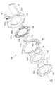
図2は、主絞り羽根112および副絞り羽根111を備えた光量調節装置100の側面拡大図である。図3は光量調節装置100の分解斜視図である。図4は光量調節装置100と第4移動枠44の斜視図であり、(a)はレンズ鏡筒1が広角の状態、(b)は望遠の状態である。(Structure of light quantity control device)
FIG. 2 is an enlarged side view of the light amount adjusting
光量調節装置100は、固定枠101、固定部材105、絞り駆動用モータ121、第1カム部材104、主絞り羽根112(第1羽根)、基板103、副絞り羽根111(第2羽根)および第2カム部材102を備える。
これらの固定枠101、固定部材105、第1カム部材104、基板103、および第2カム部材102は、円環形状が好ましいが、これに限定されず、たとえば円周方向の一部が切りかかれたC字型や、外周や内周の一部に切欠きを設けてもよい。The light amount adjusting
The
固定枠101は、光量調節装置100の土台となる枠である。固定枠101の外周面よりは内径側に、基板103と第1カム部材104とが回転可能に配置され、第2カム部材102と固定部材105とが固定されている。 The
固定部材105は、光量調節装置100のカメラボディ2側に配置されている。固定部材105は、絞り駆動用モータ121を固定するための円環状部材であり、光軸OA方向カメラ側に絞り駆動用モータ121が取り付けられている。なお、絞り駆動用モータ121の取付位置はこれに限定されず、例えば、光軸OA方向被写体側であってもよい。 The
絞り駆動用モータ121は、本実施形態ではステッピングモータであるが、これに限定されず、他の種類のモータ、例えばDCモータ、超音波モータ、ボイスコイルモータなどであってもよい。
絞り駆動用モータ121の回転軸には、ピニオンギア121aが取り付けられ、ピニオンギア121aは光軸OA方向被写体側に突出している。Although the
A
固定部材105の光軸OA方向被写体側には、第1カム部材104が配置されている。第1カム部材104は、主絞り羽根112を小絞りまで絞り込み可能にするための第1カム溝104aが形成された主絞り用の回転部材(いわゆる主絞り矢車)である。
第1カム部材104の外縁には、上述のピニオンギア121aが噛合するセグメントギア104bが形成されている。なお、動力伝達方法は、動力伝達構造であれば、このようなピニオンギアとセグメントギアの構成に限るものではない。
第1カム部材104は、固定枠101と固定部材105との間に挟み込まれることによって、光軸OA方向に位置決めされている。第1カム部材104の光軸OA方向の位置決めは、固定枠101または固定部材105にバヨネット係合などによって行っても良く、特に限定されない。The
On the outer edge of the
The
第1カム部材104の被写体側には、主絞り羽根112が配置されている。主絞り羽根112は、この枚数に限定されないが、本実施形態において9枚設けられ、互いに重なることにより光軸OAを中心とした主絞り開口を形成している。
主絞り羽根112は、それぞれ、薄板状部材で形成され、円周方向に湾曲した略三角形状を有している。
主絞り羽根112は、それぞれ、第1カム部材104の第1カム溝104aに挿入される主絞り移動部112aと、基板103の支持孔103b(後述)に挿入される主絞り保持部112bと、を有する。The
Each of the
The
なお、本実施形態において、主絞り移動部112aと主絞り保持部112bとはピン形状であるが、これに限定されるものではない。また、例えば基板103の支持孔103b(後述)に主絞り保持部112bが挿入される形態を説明したが、これに限定されず、基板103にピンを設けて主絞り羽根112に穴を設けても良い。 In the present embodiment, the main
本絞り羽根112の被写体側には、基板103が配置されている。基板103は、主絞り羽根112と副絞り羽根111とを支持して回転させる回転部材(いわゆるハチノス)である。 The
基板103は、中央が開口した円板部材で、円周に沿って複数の支持孔103aが設けられている。支持孔103aには、主絞り羽根112の主絞り保持部112bと、副絞り羽根111の副絞り保持部111b(後述)とが交互に挿入される。 The
支持孔103aは主絞り保持部112b用と、副絞り保持部111b用とが同じ大きさで光軸OAから同一径に配置されているが、これに限定されず、異なる径に配置されていてもよい。 The support holes 103a are the same in size for the main
基板103は、固定枠101と第2カム部材102との間に挟み込まれることによって、光軸OA方向に位置決めされている。基板103の光軸OA方向の位置決めは、固定枠101または第2カム部材102にバヨネット係合などによって行っても良く、特に限定されない。また、基板103は、図示しないバネによって、被写体側からみたときの反時計回りの方向(図3において矢印Xで示す)に付勢されている。 The
基板103の被写体側には、副絞り羽根111が配置されている。副絞り羽根111は、本実施形態において9枚設けられ、互いに重なることにより光軸OAを中心とした開放口径を規定している。副絞り羽根111はそれぞれ、薄板状部材で形成され、円周方向に湾曲した略三角形状を有している。
副絞り羽根111はそれぞれ、第2カム部材102のカム溝に挿入される副絞り移動部111aと、基板103の支持孔103aに挿入される副絞り保持部111bと、を有する。A
Each
なお、本実施形態において、副絞り移動部111aと副絞り保持部111bとはピン形状であるが、これに限定されるものではない。また、例えば基板103の支持孔103bに副絞り保持部111bが挿入される形態を説明したが、これに限定されず、基板103にピンを設けて主絞り羽根112に穴を設けても良い。 In addition, in the present embodiment, the
基板103の外周から光軸OA方向カメラボディ側に、図3に示すように駆動レバー62が延びている。駆動レバー62は、基板103の円周部から折れ曲がって第4移動枠44側に延びる腕状の部分である。駆動レバー62の先端には、L字型の掛合部62aが形成されている。
なお、駆動レバー62と連結キー61(後述)との係合が可能であれば、掛合部62aの形状はL字型でなくても良く、また、駆動レバー62と連結キー61との係合が可能であれば、掛合部62aを設けなくてもよい。A
If the
基板103の被写体側には、第2カム部材102が配置されている。第2カム部材102は副絞り羽根111の開放口径を決定するためのカム溝102aが形成された副絞り用の固定部材、いわゆる副絞り矢車である。
本実施形態によると、主絞りと副絞りが、土台となる一つの固定部材に嵌合させ、一つのユニットとして形成されている。The
According to this embodiment, the main diaphragm and the sub diaphragm are fitted into one fixing member which is a base, and are formed as one unit.
第4移動枠44から光軸OA方向被写体側に向かって、連結キー(連結部)61が延びている。連結キー61は、駆動レバー62の掛合部62aと当接して駆動レバー62を時計回りの方向(矢印Xと反対方向)に押圧することにより基板103を回転駆動する。
連結キー61における、掛合部62aと当接する側の側面61aは、図3に示すように光軸OA方向の先端側に向かうに従って、図中矢印Yの方向(矢印Xと反対方向)に傾いている。
なお、本実施形態では、連結キー61を第4移動枠44に設けたが、これに限定されず、ズーミング等によって光量調節部材100との相対距離が変更される場合は、固定部に設けてもよい。A connecting key (connecting portion) 61 extends from the fourth moving
The
In the present embodiment, the
図4(a)はレンズ鏡筒1が広角の状態での光量調節装置100と第4移動枠44との斜視図であり、連結キー61と駆動レバー62との位置関係を示す。
図示するように、レンズ鏡筒1が広角の状態において掛合部62aは、連結キー61の側面61aの先端部Aと当接する。FIG. 4A is a perspective view of the light
As shown in the figure, when the
図4(b)はレンズ鏡筒1が望遠の状態での光量調節装置100と第4移動枠44との斜視図であり、連結キー61と駆動レバー62との位置関係を示す。
図示するように、レンズ鏡筒1が望遠の状態において掛合部62aは、連結キー61の側面61aの基端部Bと当接する。
基端部Bは先端部Aに対して、被写体側から見たときに。光軸OAを中心とした周方向において反時計回り(X方向)に回り込んだ位置にある。FIG. 4B is a perspective view of the light
As shown in the figure, when the
The base end portion B is viewed from the subject side with respect to the tip end portion A. It is located counterclockwise (X direction) in the circumferential direction about the optical axis OA.
(光量調節装置の動作)
次に、本実施形態のレンズ鏡筒1の光量調節装置100の動作について説明する。(Operation of light intensity control device)
Next, the operation of the light
(主絞り羽根の絞り動作)
主絞り羽根112は、第1カム部材104と、基板103と、絞り駆動用モータ121とによって、いわゆる電磁絞りを構成する。
駆動用モータ121が駆動されると、ピニオンギア121aとセグメントギア104bの噛合により、第1カム部材104が光軸OAを中心として回転する。(Aperture operation of the main aperture blade)
The
When the
第1カム部材104が回転すると、第1カム部材104の第1カム溝104aに挿入された主絞り移動部112aの位置が変化する。
この主絞り移動部112aの位置の変化により、主絞り羽根112は、基板103の支持孔103aに挿入された保持部112bを中心として回転し、複数の主絞り羽根112で規定される絞り径が変更される。When the
Due to the change in the position of the main
(副絞り羽根の開放径の変更動作)
(広角側)
ここで、レンズ鏡筒1が、図4(a)で示す広角の状態の場合、駆動レバー62の掛合部62aは連結キー61の先端部Aと当接している。
このとき、副絞り羽根111は、図4(a)で示すように光量調節装置100の穴100aから若干突き出した状態であり、副絞り羽根111で形成される開放径111cは、最大開放径から若干絞られた径となる。この広角端においては、この状態を開放状態として、撮影時における主絞り羽根112の絞り動作が行われる。(Operation of changing the opening diameter of the auxiliary diaphragm blade)
(Wide-angle side)
Here, when the
At this time, the
(広角から望遠までの間)
ユーザーにより操作されてズームリング52が回転すると、ズームリング52と基板103とは機械的に連結しているので、基板103が回転する。(Between wide-angle and telephoto)
When the
すなわち、ズームリング52の回転に連動して、第4移動枠44が光軸OA方向に直進移動する。
基板103は、上述したように、駆動レバー62が連結キー61と当接するように矢印Xの方向にバネ付勢されている。
そして、上述したように、連結キー61における掛合部62aと当接する側面61aは、図3に示すように光軸OA方向の先端側に向かって、矢印Xと反対の矢印Yの方向に傾いている。
このため、第4移動枠44の基板103側への移動により、駆動レバー62は、連結キー61の側面61aに沿ってX方向に回転する。
駆動レバー62は基板103に連結しているため、基板103もX方向に回転する。That is, in association with the rotation of the
As described above, the
Then, as described above, the
Therefore, the
Since the
本実施形態において、基板103がX方向に回転すると、副絞り羽根111は開放径111cを大きくするように移動する。
なお、レンズ鏡筒1は、広角と望遠との中間のどの状態においても、ズームの停止が可能である。そして、その停止された位置において副絞り羽根111で形成される径を開放径111cとして、撮影時における主絞り羽根112の絞り動作を行うことができる。また、第1カム部材104は、基板103がX方向に回転する際、駆動用モータ121の保持トルク(無通電)により回転せずにX方向における位置が固定される。In the present embodiment, when the
The
(望遠側)
レンズ鏡筒1が、図4(b)で示す望遠の状態の場合、駆動レバー62の掛合部62aは、連結キー61の基端部Bと当接する。このとき副絞り羽根111は、基板103と第1カム部材104との間に完全に収納され、開放絞り径は最も大きくなる(上述の光量調節装置100の穴100aの大きさ)。
そして、望遠端においては、この状態を開放状態として、撮影時における主絞り羽根112の絞り動作が行われる。(Telephoto side)
When the
At the telephoto end, this state is set to the open state, and the diaphragm operation of the
なお、本実施形態では、広角側において光量調節装置100と第4移動枠44との間の距離が広く、望遠側において光量調節装置100と第4移動枠44との間の距離が狭くなる形態について説明した。しかし、これに限定されず、その逆であってもよい。 In this embodiment, the distance between the light
(本実施形態の効果)
(1)以上、本実施形態の光量調節装置100は、ユーザーにより操作されるズームリング52を有するレンズ鏡筒1の光量調節装置100である。
この光量調節装置100は、互いに重なることにより光軸OAを中心とした第1開口を形成する複数の主絞り羽根112と、少なくとも一部が主絞り羽根112に対向するように配置され、複数の第1カム溝104aを有する第1カム部材104と、主絞り羽根112に保持され、第1カム溝104aに沿って移動する第1移動部112aと、主絞り羽根112の第1カム部材104とは反対側に配置され、第1カム部材104と光軸OA回りに相対回転可能な基板103と、基板103と主絞り羽根112とに保持される第1保持部112bと、第1カム部材104を相対回転させる絞り駆動用モータ121と、ズームリング52と機械的に連結され、基板103を相対回転させる連結キー61とを備える。
そして、基板103と第1カム部材104とが相対回転することにより、第1開口の径が変化する。(Effect of this embodiment)
(1) As described above, the light
This light
Then, the relative rotation between the
本実施形態の光量調節装置100によると、主絞り羽根112の絞り口径の補正は、ズームリング52と機械的に連結されて基板103を相対回転させる連結キー61により行われる。
たとえば、絞り口径を変化させるカム部材の回転量を電気的に補正することで主絞りの絞り口径の補正を行う場合と比較すると、主絞り口径の補正を、より簡便に行うことができる。
単に、ズームリング52を回転することにより、その回転と連動して機械的に絞り羽根112の絞り口径の補正が行われるので、電気的な処理が不要であり、消費電力が少なくて済む。
また、通電していない状態でも絞り羽根112の絞り口径の補正を行うことができる。According to the light
For example, the main aperture diameter can be corrected more easily than in the case where the aperture diameter of the main aperture is corrected by electrically correcting the rotation amount of the cam member that changes the aperture diameter.
By simply rotating the
Further, the aperture diameter of the
(2)本実施形態の光量調節装置100によると、ズームリング52を操作することにより変倍または焦点調節が可能であり、連結キー61は、変倍または焦点調節の際に光軸OA方向に移動する第4移動枠44に固定されている。(2) According to the light
これによると、簡易な構成で部品点数を増やさずに、基板103を相対回転させて主絞り羽根112の絞り口径の補正と、副絞り羽根111の開放径11cの変更とができる。 According to this, it is possible to correct the aperture diameter of the
(3)本実施形態の光量調節装置100によると、連結キー61が基板103を相対回転させる際、駆動用モータ121は第1カム部材104を光軸OA回りに回転しないように保持する。
これによると、連結キー61が基板103を相対回転させる際に、第1カム部材104の光軸OA回りの回転が防止されるので、安定して基板103を相対回転させることができる。(3) According to the light
According to this, when the
(4)本実施形態の光量調節装置100によると、レンズ鏡筒1の開放径を規定する第2羽根111を備える。(4) According to the light
(5)本実施形態の光量調節装置100によると、レンズ鏡筒1の開放径を規定する第2羽根111と、少なくとも一部が第2羽根111に対向するように配置され、複数の第2カム溝102aを有し、基板103と光軸OA回りに相対回転可能な第2カム部材102と、第2羽根111に保持され、第2カム溝102aに沿って移動する第2移動部111aと、基板103と第2羽根111とに保持される第2保持部111bとを備え、駆動レバー62は、基板103を第1カム部材104および第2カム部材102に対して相対回転させる。(5) According to the light
比較形態として、主絞りおよび副絞りがそれぞれ、絞り羽根と、その絞り羽根を保持する基板と、絞り羽根を保持して回動することで絞り羽根を開閉動作させて絞り口径を変化させるカム部材と、を備えている場合、円板部材が4枚必要となる。このため、部材の枚数が1枚多いので大型化する。
また、主絞りと副絞りの光軸ズレが生じる可能性がある。
また、副絞りと主絞り羽根とをそれぞれ独立して補正するので、主絞り羽根と副絞り羽根の間に口径ズレが発生しやすくなる。As a comparative form, each of the main diaphragm and the sub diaphragm, a diaphragm blade, a substrate holding the diaphragm blade, and a cam member for changing the diaphragm aperture by opening and closing the diaphragm blade by holding and rotating the diaphragm blade. In the case of including the and, four disk members are required. Therefore, since the number of members is one, the size is increased.
Further, there is a possibility that the optical axes of the main diaphragm and the sub diaphragm will shift.
In addition, since the sub diaphragm and the main diaphragm blade are independently corrected, the aperture deviation is likely to occur between the main diaphragm blade and the sub diaphragm blade.
しかし、本実施形態によると、第2羽根111は、第2カム部材102と基板103とに保持される。ここで、基板103は第1羽根112の保持部材として共通である。このため光量調節装置100の小型化が可能である。 However, according to this embodiment, the
また、共通化した部材をズーミングによって回転し、副絞り羽根111の開放径を補正するとともに主絞り羽根112の絞り口径を補正することで、口径ズレを防ぐことができる。
主絞り羽根112と副絞り羽根111を一つの部材に嵌合させ、一つのユニットとすることで、光軸ズレを防ぐこともできる。Further, by rotating the common member by zooming to correct the opening diameter of the
The optical axis shift can be prevented by fitting the
(変形形態)
以上、説明した実施形態に限定されることなく、以下に示すような種々の変形や変更が可能であり、それらも本発明の範囲内である。
本実施形態は、ズーミング操作の際に、F値を一定にするために、各焦点距離や撮影距離に応じて絞りの開放口径および絞り口径を補正する形態について説明した。
しかし、本実施形態はそれに限定されず、マクロレンズ等の場合にF値を一定にするために、各焦点距離や撮影距離に応じて絞りの開放口径および絞り口径を補正する場合に用いてもよい。
また、本実施形態は、ズーミング操作の際、連結キー61と駆動レバー62との係合により基板103を回動させるが、基板103の回動方法はこの限りではない。例えば、基板103から外周側に突出させた部材を設け、ズーミング操作の際に回転する部材に係合させることとしてもよい。また、光量調節装置100自体が光軸方向前後に動いて、基板103が他部材に係合して回転することとしてもよい。また、光量調節装置100自体が光軸方向前後に動く際、基板103は他部材に係合して回転せず、第1カム部材104および第2カム部材102が回転する等、どんな形であれ基板103とカム部材とが相対的に回転していればよい。(Variation)
As described above, the present invention is not limited to the embodiment described above, and various modifications and changes as described below are possible, which are also within the scope of the present invention.
In the present embodiment, a description has been given of the mode in which the aperture diameter and the aperture diameter of the aperture are corrected according to each focal length and the shooting distance in order to keep the F value constant during the zooming operation.
However, the present embodiment is not limited to this, and in the case of a macro lens or the like, in order to make the F value constant, it may be used in the case of correcting the open aperture and aperture diameter of the aperture according to each focal length or shooting distance. Good.
Further, in the present embodiment, the
本実施形態では光量調節装置100がレンズ鏡筒1に設けられている例について説明したが、これに限定されず、他の光学機器として、撮像装置、交換レンズに設けてもよい。
なお、実施形態に限らず、他の構成を適宜組み合わせて用いることもできるが、詳細な説明は省略する。また、本発明は以上説明した実施形態によって限定されることはない。In the present embodiment, an example in which the light
Note that the present invention is not limited to the embodiment, and other configurations can be appropriately combined and used, but detailed description thereof will be omitted. Further, the present invention is not limited to the embodiments described above.
1:レンズ鏡筒、2:カメラボディ、11:第1固定筒、12:第2固定筒、13:第3固定筒、21:第1カム筒、22:第2カム筒、31:第1移動カム筒、32:第2移動カム筒、41:移動枠、42:第2移動枠、43:第3移動枠、44:第4移動枠、51:フォーカスリング、52:ズームリング、61:連結キー、61a:側面、62:駆動レバー、62a:掛合部、71:マウント、100:光量調節装置、101:固定枠、102:第2カム部材、102a:第2カム溝、103:基板、103a:支持孔、103b:支持孔、104:第1カム部材、104a:第1カム溝、104b:セグメントギア、105:固定部材、111:第2羽根、111a:第2移動部、111b:保持部、112:羽根、112a:第1移動部、112b:第1保持部、121:駆動用モータ、121a:ピニオンギア 1: Lens barrel, 2: Camera body, 11: First fixed barrel, 12: Second fixed barrel, 13: Third fixed barrel, 21: First cam barrel, 22: Second cam barrel, 31: First Moving cam barrel, 32: second moving cam barrel, 41: moving frame, 42: second moving frame, 43: third moving frame, 44: fourth moving frame, 51: focus ring, 52: zoom ring, 61: Connection key, 61a: side surface, 62: drive lever, 62a: engaging portion, 71: mount, 100: light amount adjusting device, 101: fixed frame, 102: second cam member, 102a: second cam groove, 103: substrate, 103a: support hole, 103b: support hole, 104: first cam member, 104a: first cam groove, 104b: segment gear, 105: fixing member, 111: second blade, 111a: second moving part, 111b: holding Part, 112: blade, 112a: first moving part, 112b: first holding part, 121: drive motor, 121a: pinion gear
Claims (7)
Translated fromJapanese互いに重なることにより光軸を中心とした第1開口を形成する複数の第1羽根と、
前記第1開口とは異なる径の第2開口を形成する複数の第2羽根と、
前記第1羽根の少なくとも一部および前記第2羽根の少なくとも一部が係合する基板と、
前記第1羽根の少なくとも一部が係合し、前記基板に対して相対回転可能な第1カム部材と、
前記レンズ鏡筒の光軸方向において、前記基板に対して相対的に移動可能な移動部材と、を備え、
前記基板は、前記移動部材と接触する接触部を有し、前記移動部材に対して相対的に回転し、
前記第1カム部材が前記基板に対して相対的に回転することにより、前記第1開口の径が変化し、
前記基板が前記移動部材に対して相対的に回転することにより、前記第2開口の径が変化する光量調節装置。A light quantity adjusting device for a lens barrel,
A plurality of first blades that form a first opening about the optical axis by overlapping each other;
A plurality of second blades forming a second opening having a diameter different from that of the first opening;
A substrate with which at least a portion of the first blade and at least a portion of the second blade are engaged;
A first cam member that is engaged with at least a portion of the first blade and is rotatable relative to the substrate;
A moving member that is movable relative to the substrate in the optical axis direction of the lens barrel,
The substrate has a contact portion that comes into contact with the moving member, rotates relative to the moving member,
By rotating the first cam member relative to the substrate, the diameter of the first opening changes,
A light amount adjusting device in whicha diameter of the second opening changes as thesubstrate rotates relative to the moving member .
前記移動部材が前記基板に対して相対的に移動することにより、前記基板は前記移動部材に対して相対的に回転する光量調節装置。The light quantity adjusting device according to claim 1, wherein
The light amount adjusting device, wherein the substrate relatively rotates with respect to the moving member when the moving member relatively moves with respect to the substrate.
前記第1カム部材を前記基板に対して相対回転させる駆動部を備える光量調節装置。The light quantity adjusting device according to claim 1or 2 , wherein
A light amount adjusting device comprising a driving unit that rotates the first cam member relative to the substrate.
前記基板が前記移動部材に対して相対的に回転する際、
前記駆動部は、前記第1カム部材を光軸回りに回転しないように保持する光量調節装置。The light quantity adjusting device according to claim3 ,
When the substrate rotates relative to the moving member,
The drive unit is a light amount adjustment device that holds the first cam member so as not to rotate around the optical axis.
前記第2開口の径は、前記レンズ鏡筒の開放径である光量調節装置。A light amount adjusting device according to any one of claims1-4,
The diameter of the second opening is a light amount adjusting device, which is an opening diameter of the lens barrel.
前記第2羽根の少なくとも一部が係合する第2カム部材を備え、
前記基板は、前記第2カム部材に対して相対的に回転する光量調節装置。A light amount adjusting device according to any one of claims 1 to5
A second cam member with which at least a part of the second blade is engaged,
The light amount adjusting device, wherein the substrate rotates relative to the second cam member.
Optics comprising a light amount adjustment device according to any one of claims1-6.
Priority Applications (1)
| Application Number | Priority Date | Filing Date | Title |
|---|---|---|---|
| JP2015149286AJP6701638B2 (en) | 2015-07-29 | 2015-07-29 | Light quantity adjusting device and optical instrument |
Applications Claiming Priority (1)
| Application Number | Priority Date | Filing Date | Title |
|---|---|---|---|
| JP2015149286AJP6701638B2 (en) | 2015-07-29 | 2015-07-29 | Light quantity adjusting device and optical instrument |
Publications (2)
| Publication Number | Publication Date |
|---|---|
| JP2017032632A JP2017032632A (en) | 2017-02-09 |
| JP6701638B2true JP6701638B2 (en) | 2020-05-27 |
Family
ID=57986177
Family Applications (1)
| Application Number | Title | Priority Date | Filing Date |
|---|---|---|---|
| JP2015149286AActiveJP6701638B2 (en) | 2015-07-29 | 2015-07-29 | Light quantity adjusting device and optical instrument |
Country Status (1)
| Country | Link |
|---|---|
| JP (1) | JP6701638B2 (en) |
Families Citing this family (1)
| Publication number | Priority date | Publication date | Assignee | Title |
|---|---|---|---|---|
| CN114942557B (en)* | 2022-05-13 | 2024-01-26 | 湖南长步道光学科技有限公司 | Diaphragm adjusting device and lens with same |
Family Cites Families (5)
| Publication number | Priority date | Publication date | Assignee | Title |
|---|---|---|---|---|
| JPS56138727A (en)* | 1980-03-31 | 1981-10-29 | Matsushita Electric Works Ltd | Iris shutter |
| JPH01171428U (en)* | 1988-05-16 | 1989-12-05 | ||
| JP2000250093A (en)* | 1999-02-25 | 2000-09-14 | Canon Inc | Light amount adjusting device and optical apparatus having the same |
| EP1939680B1 (en)* | 2006-12-25 | 2013-06-19 | Nikon Corporation | Aperture mechanism, optical apparatus and manufacturing method thereof |
| JP5256613B2 (en)* | 2007-01-17 | 2013-08-07 | 株式会社ニコン | Aperture mechanism and optical equipment |
- 2015
- 2015-07-29JPJP2015149286Apatent/JP6701638B2/enactiveActive
Also Published As
| Publication number | Publication date |
|---|---|
| JP2017032632A (en) | 2017-02-09 |
Similar Documents
| Publication | Publication Date | Title |
|---|---|---|
| JP4817876B2 (en) | Lens barrel and camera system | |
| CN102207599B (en) | Lens barrel assembly having iris diaphragm device and projector | |
| US9030765B2 (en) | Optical apparatus including decentering/tilting adjustment mechanism | |
| JP4572964B2 (en) | Lens barrel and imaging device | |
| JP5868016B2 (en) | Optical device | |
| JP6584070B2 (en) | Lens barrel and optical equipment | |
| WO2017115465A1 (en) | Lens barrel and camera provided with same | |
| US9723187B2 (en) | Light amount adjusting apparatus, lens barrel, optical apparatus, and imaging apparatus | |
| JP2013029693A (en) | Light amount control device and optical apparatus | |
| JP3582329B2 (en) | Lens barrel | |
| US10139584B2 (en) | Lens apparatus and optical apparatus | |
| JP6701638B2 (en) | Light quantity adjusting device and optical instrument | |
| JP7115627B2 (en) | Aperture mechanism and optical equipment | |
| US20180039042A1 (en) | Lens barrel and imaging device | |
| JP5912871B2 (en) | Aperture correction mechanism and lens barrel | |
| JP5475554B2 (en) | Lens barrel | |
| JP2012211977A (en) | Light quantity adjusting device and optical instrument equipped with the same | |
| JP2016130765A (en) | Lens barrel, optical device, and imaging device | |
| JP6555064B2 (en) | Light amount adjustment mechanism, lens barrel and camera | |
| JP7301606B2 (en) | Light control device and optical equipment | |
| JP2015026062A (en) | Lens-barrel | |
| JP7024834B2 (en) | Aperture unit, lens barrel and camera | |
| JP4839290B2 (en) | Lens barrel and optical equipment | |
| JP2003057721A (en) | Camera | |
| JP6760446B2 (en) | Aperture unit, lens barrel and camera |
Legal Events
| Date | Code | Title | Description |
|---|---|---|---|
| RD03 | Notification of appointment of power of attorney | Free format text:JAPANESE INTERMEDIATE CODE: A7423 Effective date:20161003 | |
| RD04 | Notification of resignation of power of attorney | Free format text:JAPANESE INTERMEDIATE CODE: A7424 Effective date:20161003 | |
| A621 | Written request for application examination | Free format text:JAPANESE INTERMEDIATE CODE: A621 Effective date:20180627 | |
| A977 | Report on retrieval | Free format text:JAPANESE INTERMEDIATE CODE: A971007 Effective date:20190205 | |
| A131 | Notification of reasons for refusal | Free format text:JAPANESE INTERMEDIATE CODE: A131 Effective date:20190319 | |
| A601 | Written request for extension of time | Free format text:JAPANESE INTERMEDIATE CODE: A601 Effective date:20190516 | |
| A521 | Request for written amendment filed | Free format text:JAPANESE INTERMEDIATE CODE: A523 Effective date:20190717 | |
| A131 | Notification of reasons for refusal | Free format text:JAPANESE INTERMEDIATE CODE: A131 Effective date:20200108 | |
| A521 | Request for written amendment filed | Free format text:JAPANESE INTERMEDIATE CODE: A523 Effective date:20200306 | |
| TRDD | Decision of grant or rejection written | ||
| A01 | Written decision to grant a patent or to grant a registration (utility model) | Free format text:JAPANESE INTERMEDIATE CODE: A01 Effective date:20200407 | |
| A61 | First payment of annual fees (during grant procedure) | Free format text:JAPANESE INTERMEDIATE CODE: A61 Effective date:20200420 | |
| R150 | Certificate of patent or registration of utility model | Ref document number:6701638 Country of ref document:JP Free format text:JAPANESE INTERMEDIATE CODE: R150 | |
| R250 | Receipt of annual fees | Free format text:JAPANESE INTERMEDIATE CODE: R250 | |
| R250 | Receipt of annual fees | Free format text:JAPANESE INTERMEDIATE CODE: R250 | |
| R250 | Receipt of annual fees | Free format text:JAPANESE INTERMEDIATE CODE: R250 |